EP3486468A2 - Steuerungsvorrichtung für motor, motor, verfahren zur steuerung des motors und computerprogrammprodukt - Google Patents
Steuerungsvorrichtung für motor, motor, verfahren zur steuerung des motors und computerprogrammprodukt Download PDFInfo
- Publication number
- EP3486468A2 EP3486468A2 EP18204785.2A EP18204785A EP3486468A2 EP 3486468 A2 EP3486468 A2 EP 3486468A2 EP 18204785 A EP18204785 A EP 18204785A EP 3486468 A2 EP3486468 A2 EP 3486468A2
- Authority
- EP
- European Patent Office
- Prior art keywords
- combustion
- engine
- reference value
- cylinder
- ignition
- Prior art date
- Legal status (The legal status is an assumption and is not a legal conclusion. Google has not performed a legal analysis and makes no representation as to the accuracy of the status listed.)
- Granted
Links
Images





Classifications
-
- F—MECHANICAL ENGINEERING; LIGHTING; HEATING; WEAPONS; BLASTING
- F02—COMBUSTION ENGINES; HOT-GAS OR COMBUSTION-PRODUCT ENGINE PLANTS
- F02D—CONTROLLING COMBUSTION ENGINES
- F02D41/00—Electrical control of supply of combustible mixture or its constituents
- F02D41/30—Controlling fuel injection
- F02D41/3011—Controlling fuel injection according to or using specific or several modes of combustion
- F02D41/3017—Controlling fuel injection according to or using specific or several modes of combustion characterised by the mode(s) being used
- F02D41/3035—Controlling fuel injection according to or using specific or several modes of combustion characterised by the mode(s) being used a mode being the premixed charge compression-ignition mode
- F02D41/3041—Controlling fuel injection according to or using specific or several modes of combustion characterised by the mode(s) being used a mode being the premixed charge compression-ignition mode with means for triggering compression ignition, e.g. spark plug
-
- F—MECHANICAL ENGINEERING; LIGHTING; HEATING; WEAPONS; BLASTING
- F02—COMBUSTION ENGINES; HOT-GAS OR COMBUSTION-PRODUCT ENGINE PLANTS
- F02B—INTERNAL-COMBUSTION PISTON ENGINES; COMBUSTION ENGINES IN GENERAL
- F02B1/00—Engines characterised by fuel-air mixture compression
- F02B1/02—Engines characterised by fuel-air mixture compression with positive ignition
- F02B1/08—Engines characterised by fuel-air mixture compression with positive ignition with separate admission of air and fuel into cylinder
- F02B1/10—Methods of operating
-
- F—MECHANICAL ENGINEERING; LIGHTING; HEATING; WEAPONS; BLASTING
- F02—COMBUSTION ENGINES; HOT-GAS OR COMBUSTION-PRODUCT ENGINE PLANTS
- F02B—INTERNAL-COMBUSTION PISTON ENGINES; COMBUSTION ENGINES IN GENERAL
- F02B1/00—Engines characterised by fuel-air mixture compression
- F02B1/12—Engines characterised by fuel-air mixture compression with compression ignition
- F02B1/14—Methods of operating
-
- F—MECHANICAL ENGINEERING; LIGHTING; HEATING; WEAPONS; BLASTING
- F02—COMBUSTION ENGINES; HOT-GAS OR COMBUSTION-PRODUCT ENGINE PLANTS
- F02D—CONTROLLING COMBUSTION ENGINES
- F02D13/00—Controlling the engine output power by varying inlet or exhaust valve operating characteristics, e.g. timing
- F02D13/02—Controlling the engine output power by varying inlet or exhaust valve operating characteristics, e.g. timing during engine operation
- F02D13/0261—Controlling the valve overlap
-
- F—MECHANICAL ENGINEERING; LIGHTING; HEATING; WEAPONS; BLASTING
- F02—COMBUSTION ENGINES; HOT-GAS OR COMBUSTION-PRODUCT ENGINE PLANTS
- F02D—CONTROLLING COMBUSTION ENGINES
- F02D35/00—Controlling engines, dependent on conditions exterior or interior to engines, not otherwise provided for
- F02D35/02—Controlling engines, dependent on conditions exterior or interior to engines, not otherwise provided for on interior conditions
- F02D35/023—Controlling engines, dependent on conditions exterior or interior to engines, not otherwise provided for on interior conditions by determining the cylinder pressure
-
- F—MECHANICAL ENGINEERING; LIGHTING; HEATING; WEAPONS; BLASTING
- F02—COMBUSTION ENGINES; HOT-GAS OR COMBUSTION-PRODUCT ENGINE PLANTS
- F02D—CONTROLLING COMBUSTION ENGINES
- F02D37/00—Non-electrical conjoint control of two or more functions of engines, not otherwise provided for
- F02D37/02—Non-electrical conjoint control of two or more functions of engines, not otherwise provided for one of the functions being ignition
-
- F—MECHANICAL ENGINEERING; LIGHTING; HEATING; WEAPONS; BLASTING
- F02—COMBUSTION ENGINES; HOT-GAS OR COMBUSTION-PRODUCT ENGINE PLANTS
- F02D—CONTROLLING COMBUSTION ENGINES
- F02D41/00—Electrical control of supply of combustible mixture or its constituents
- F02D41/0025—Controlling engines characterised by use of non-liquid fuels, pluralities of fuels, or non-fuel substances added to the combustible mixtures
- F02D41/0047—Controlling exhaust gas recirculation [EGR]
- F02D41/005—Controlling exhaust gas recirculation [EGR] according to engine operating conditions
- F02D41/0057—Specific combustion modes
-
- F—MECHANICAL ENGINEERING; LIGHTING; HEATING; WEAPONS; BLASTING
- F02—COMBUSTION ENGINES; HOT-GAS OR COMBUSTION-PRODUCT ENGINE PLANTS
- F02D—CONTROLLING COMBUSTION ENGINES
- F02D41/00—Electrical control of supply of combustible mixture or its constituents
- F02D41/0025—Controlling engines characterised by use of non-liquid fuels, pluralities of fuels, or non-fuel substances added to the combustible mixtures
- F02D41/0047—Controlling exhaust gas recirculation [EGR]
- F02D41/0077—Control of the EGR valve or actuator, e.g. duty cycle, closed loop control of position
-
- F—MECHANICAL ENGINEERING; LIGHTING; HEATING; WEAPONS; BLASTING
- F02—COMBUSTION ENGINES; HOT-GAS OR COMBUSTION-PRODUCT ENGINE PLANTS
- F02D—CONTROLLING COMBUSTION ENGINES
- F02D41/00—Electrical control of supply of combustible mixture or its constituents
- F02D41/30—Controlling fuel injection
- F02D41/38—Controlling fuel injection of the high pressure type
- F02D41/40—Controlling fuel injection of the high pressure type with means for controlling injection timing or duration
- F02D41/401—Controlling injection timing
-
- F—MECHANICAL ENGINEERING; LIGHTING; HEATING; WEAPONS; BLASTING
- F02—COMBUSTION ENGINES; HOT-GAS OR COMBUSTION-PRODUCT ENGINE PLANTS
- F02P—IGNITION, OTHER THAN COMPRESSION IGNITION, FOR INTERNAL-COMBUSTION ENGINES; TESTING OF IGNITION TIMING IN COMPRESSION-IGNITION ENGINES
- F02P5/00—Advancing or retarding ignition; Control therefor
- F02P5/04—Advancing or retarding ignition; Control therefor automatically, as a function of the working conditions of the engine or vehicle or of the atmospheric conditions
- F02P5/145—Advancing or retarding ignition; Control therefor automatically, as a function of the working conditions of the engine or vehicle or of the atmospheric conditions using electrical means
- F02P5/15—Digital data processing
- F02P5/1502—Digital data processing using one central computing unit
-
- F—MECHANICAL ENGINEERING; LIGHTING; HEATING; WEAPONS; BLASTING
- F02—COMBUSTION ENGINES; HOT-GAS OR COMBUSTION-PRODUCT ENGINE PLANTS
- F02D—CONTROLLING COMBUSTION ENGINES
- F02D41/00—Electrical control of supply of combustible mixture or its constituents
- F02D41/0002—Controlling intake air
- F02D2041/0015—Controlling intake air for engines with means for controlling swirl or tumble flow, e.g. by using swirl valves
-
- F—MECHANICAL ENGINEERING; LIGHTING; HEATING; WEAPONS; BLASTING
- F02—COMBUSTION ENGINES; HOT-GAS OR COMBUSTION-PRODUCT ENGINE PLANTS
- F02D—CONTROLLING COMBUSTION ENGINES
- F02D2200/00—Input parameters for engine control
- F02D2200/02—Input parameters for engine control the parameters being related to the engine
- F02D2200/025—Engine noise, e.g. determined by using an acoustic sensor
-
- F—MECHANICAL ENGINEERING; LIGHTING; HEATING; WEAPONS; BLASTING
- F02—COMBUSTION ENGINES; HOT-GAS OR COMBUSTION-PRODUCT ENGINE PLANTS
- F02D—CONTROLLING COMBUSTION ENGINES
- F02D2200/00—Input parameters for engine control
- F02D2200/02—Input parameters for engine control the parameters being related to the engine
- F02D2200/10—Parameters related to the engine output, e.g. engine torque or engine speed
- F02D2200/101—Engine speed
-
- F—MECHANICAL ENGINEERING; LIGHTING; HEATING; WEAPONS; BLASTING
- F02—COMBUSTION ENGINES; HOT-GAS OR COMBUSTION-PRODUCT ENGINE PLANTS
- F02D—CONTROLLING COMBUSTION ENGINES
- F02D2200/00—Input parameters for engine control
- F02D2200/50—Input parameters for engine control said parameters being related to the vehicle or its components
- F02D2200/501—Vehicle speed
-
- F—MECHANICAL ENGINEERING; LIGHTING; HEATING; WEAPONS; BLASTING
- F02—COMBUSTION ENGINES; HOT-GAS OR COMBUSTION-PRODUCT ENGINE PLANTS
- F02D—CONTROLLING COMBUSTION ENGINES
- F02D41/00—Electrical control of supply of combustible mixture or its constituents
- F02D41/0025—Controlling engines characterised by use of non-liquid fuels, pluralities of fuels, or non-fuel substances added to the combustible mixtures
- F02D41/0047—Controlling exhaust gas recirculation [EGR]
- F02D41/006—Controlling exhaust gas recirculation [EGR] using internal EGR
-
- F—MECHANICAL ENGINEERING; LIGHTING; HEATING; WEAPONS; BLASTING
- F02—COMBUSTION ENGINES; HOT-GAS OR COMBUSTION-PRODUCT ENGINE PLANTS
- F02D—CONTROLLING COMBUSTION ENGINES
- F02D41/00—Electrical control of supply of combustible mixture or its constituents
- F02D41/0025—Controlling engines characterised by use of non-liquid fuels, pluralities of fuels, or non-fuel substances added to the combustible mixtures
- F02D41/0047—Controlling exhaust gas recirculation [EGR]
- F02D41/0065—Specific aspects of external EGR control
-
- F—MECHANICAL ENGINEERING; LIGHTING; HEATING; WEAPONS; BLASTING
- F02—COMBUSTION ENGINES; HOT-GAS OR COMBUSTION-PRODUCT ENGINE PLANTS
- F02M—SUPPLYING COMBUSTION ENGINES IN GENERAL WITH COMBUSTIBLE MIXTURES OR CONSTITUENTS THEREOF
- F02M26/00—Engine-pertinent apparatus for adding exhaust gases to combustion-air, main fuel or fuel-air mixture, e.g. by exhaust gas recirculation [EGR] systems
- F02M26/13—Arrangement or layout of EGR passages, e.g. in relation to specific engine parts or for incorporation of accessories
- F02M26/22—Arrangement or layout of EGR passages, e.g. in relation to specific engine parts or for incorporation of accessories with coolers in the recirculation passage
- F02M26/33—Arrangement or layout of EGR passages, e.g. in relation to specific engine parts or for incorporation of accessories with coolers in the recirculation passage controlling the temperature of the recirculated gases
-
- Y—GENERAL TAGGING OF NEW TECHNOLOGICAL DEVELOPMENTS; GENERAL TAGGING OF CROSS-SECTIONAL TECHNOLOGIES SPANNING OVER SEVERAL SECTIONS OF THE IPC; TECHNICAL SUBJECTS COVERED BY FORMER USPC CROSS-REFERENCE ART COLLECTIONS [XRACs] AND DIGESTS
- Y02—TECHNOLOGIES OR APPLICATIONS FOR MITIGATION OR ADAPTATION AGAINST CLIMATE CHANGE
- Y02T—CLIMATE CHANGE MITIGATION TECHNOLOGIES RELATED TO TRANSPORTATION
- Y02T10/00—Road transport of goods or passengers
- Y02T10/10—Internal combustion engine [ICE] based vehicles
- Y02T10/12—Improving ICE efficiencies
-
- Y—GENERAL TAGGING OF NEW TECHNOLOGICAL DEVELOPMENTS; GENERAL TAGGING OF CROSS-SECTIONAL TECHNOLOGIES SPANNING OVER SEVERAL SECTIONS OF THE IPC; TECHNICAL SUBJECTS COVERED BY FORMER USPC CROSS-REFERENCE ART COLLECTIONS [XRACs] AND DIGESTS
- Y02—TECHNOLOGIES OR APPLICATIONS FOR MITIGATION OR ADAPTATION AGAINST CLIMATE CHANGE
- Y02T—CLIMATE CHANGE MITIGATION TECHNOLOGIES RELATED TO TRANSPORTATION
- Y02T10/00—Road transport of goods or passengers
- Y02T10/10—Internal combustion engine [ICE] based vehicles
- Y02T10/40—Engine management systems
Definitions
- the present disclosure relates to a control device for an engine, particularly, a compression-ignition engine, which executes partial compression-ignition combustion in which a mixture gas within a cylinder is partially combusted by spark-ignition (SI combustion) and then the remaining mixture gas within the cylinder is combusted by self-ignition (CI (Compression Ignition) combustion).
- SI combustion spark-ignition
- CI Self-ignition
- the present disclosure also relates to the engine, a method for controlling the engine, and a computer program product.
- HCCI Homogeneous-Charge Compression Ignition
- the HCCI combustion has issues such as a combustion start timing of the mixture gas (a timing that the mixture gas self-ignites) greatly varying due to an external factor (e.g., atmospheric temperature) and a control during a transient operation in which an engine load sharply changes is difficult.
- JP2009-108778A discloses an engine adopting a similar concept to the partial compression-ignition combustion.
- This engine causes flame propagation combustion by spark-igniting a stratified mixture gas which is formed around a spark plug by a supplementary fuel injection, and then performs a main fuel injection inside a cylinder warmed up by an effect of the flame propagation combustion, so as to combust through self-ignition the fuel injected in the main fuel injection.
- the present disclosure is made in view of the above situations and aims to provide a control device for an engine, particularly, a compression-ignition engine, which appropriately controls combustion while considering combustion noise which is actually perceived by a person(s) in a cabin.
- the present disclosure also aims to provide an engine, a method for controlling an engine, and a computer program product which appropriately controls combustion while considering combustion noise which is actually perceived by a person(s) in a cabin.
- a control device for an engine In the engine partial compression-ignition combustion is executed within at least a part of an operating range of the engine.
- the partial compression-ignition combustion including spark ignition combustion and compression ignition.
- the spark ignition combustion is to be performed by combusting a portion of a mixture gas inside a cylinder by spark ignition and followed by the compression ignition combustion.
- the compression ignition combustion is to be performed by causing the remaining mixture gas inside the cylinder to self-ignite.
- the control device includes: a detector configured to detect at least one parameter related to noise caused by the combustion inside the cylinder; and a combustion controller configured to control the combustion inside the cylinder during the partial compression-ignition combustion based on the detected parameter(s) of the detector and a reference value defined as an upper limit regarding the noise.
- the reference value is adapted to increase as a vehicle speed, an engine speed, and/or an engine load increases.
- the combustion controller is configured to control the combustion inside the cylinder during the partial compression-ignition combustion based on a combustion noise index value identified by the detected parameter of the detector and the reference value.
- the reference value is defined as an upper limit of the combustion noise index value.
- the reference value is set so that a change rate of the reference value is larger as the vehicle speed is lower.
- the reference value is set so that the change rate of the reference value is larger as the vehicle speed is lower, when the engine load remains unchanged.
- the reference value is set so that a change rate of the reference value when the vehicle speed changes while an engine load remains unchanged is larger in a low speed range in which the vehicle speed is below a given value than in a high speed range in which the vehicle speed is the given value or higher.
- a first characteristic and a second characteristic are defined in advance.
- the first characteristic is adapted to define the reference value when the engine load is fixed at a load.
- the second characteristic is adapted to define the reference value when the engine load is fixed at a load which is higher than the load of the first characteristic.
- At least the first characteristic is set so that the change rate of the reference value with respect to the vehicle speed is larger in the low speed range than in the high speed range.
- the combustion controller is configured to identify, when the engine load currently falls neither within the low load nor the high load, the reference value corresponding to the current engine load by an interpolation processing using the reference values defined for the first characteristic and the second characteristic.
- the combustion controller is configured to determine a target start timing that is a target start timing or crank angle of the compression ignition combustion as a timing at which the combustion noise index value is equal to or less than the reference value, and control the combustion inside the cylinder so as to achieve the determined target start timing.
- the detector is configured to detect pressure inside the cylinder as the parameter.
- the detector is an in-cylinder pressure sensor.
- an engine is provided.
- partial compression-ignition combustion is executed within at least a part of an operating range of the engine.
- the partial compression-ignition combustion including spark ignition combustion and compression ignition.
- the spark ignition combustion is to be performed by combusting a portion of a mixture gas inside a cylinder by spark ignition and followed by the compression ignition combustion.
- the compression ignition combustion is to be performed by causing the remaining mixture gas inside the cylinder to self-ignite.
- the engine includes the above control device.
- the engine is an on-board engine.
- a method for controlling an engine is provided.
- the partial compression-ignition combustion is executed within at least a part of an operating range of the engine.
- the partial compression-ignition combustion including spark ignition combustion and compression ignition.
- the spark ignition combustion is to be performed by combusting a portion of a mixture gas inside a cylinder by spark ignition and followed by the compression ignition combustion.
- the compression ignition combustion is to be performed by causing the remaining mixture gas inside the cylinder to self-ignite.
- the method includes: detecting at least one parameter related to noise caused by the combustion inside the cylinder; and controlling the combustion inside the cylinder during the partial compression-ignition combustion based on the detected parameter(s) of the detector and a reference value defined as an upper limit regarding the noise.
- the reference value is adapted to increase as a vehicle speed, an engine speed, and/or an engine load increases.
- the method includes controlling the combustion inside the cylinder during the partial compression-ignition combustion based on a combustion noise index value identified by the detected parameter of the detector and the reference value.
- the reference value is defined as an upper limit of the combustion noise index value.
- the computer program product includes computer-readable instructions which, when loaded and executed on a suitable system, perform the above control method.
- a control device for an on-board compression-ignition engine in which partial compression-ignition combustion including spark ignition (SI) combustion performed by combusting a portion of a mixture gas inside a cylinder by spark ignition followed by compression (CI) combustion performed by causing the remaining mixture gas inside the cylinder to self-ignite is executed within at least a part of an operating range of the engine, is provided.
- SI spark ignition
- CI compression
- the device includes a detector configured to detect a parameter related to noise caused by the combustion inside the cylinder, and a combustion controller configured to control the combustion inside the cylinder during the partial compression-ignition combustion based on a combustion noise index value identified by the detected parameter of the detector and a given reference value defined as an upper limit of the combustion noise index value, the reference value increasing as a vehicle speed increases.
- background noise sound transmitted inside a cabin as the vehicle travels and the engine operates
- background noise sound transmitted inside a cabin as the vehicle travels and the engine operates
- the reference value of the combustion noise index value is set higher as the vehicle speed increases, and the combustion is controlled based on the reference value. Therefore, the ratio of the CI combustion is increased as much as possible while keeping combustion noise which is actually perceived by the passenger to an adequate level.
- the reference value when the reference value is set uniformly disregarding the vehicle speed, the reference value needs to be set sufficiently low so that the combustion noise is not easily perceived by the passenger even when the background noise takes the smallest value, i.e., when the vehicle speed is low.
- the combustion is constantly controlled based on the low reference value, the ratio of the CI combustion may decrease significantly and the fuel efficiency improving effect may drop.
- the reference value when the reference value is set to increase as the vehicle speed increases, since the ratio of the CI combustion is not lowered excessively to reduce combustion noise more than necessary, while comfort of the passenger is properly secured, the ratio of the CI combustion is increased as much as possible to effectively improve fuel efficiency.
- the reference value may be set so that a change rate of the reference value when the vehicle speed changes while an engine load remains unchanged is larger in a low speed range in which the vehicle speed is below a given value than in a high speed range in which the vehicle speed is the given value or higher.
- the suitable reference value is set in consideration of a characteristic that the engine sound transmitted into the cabin (a mixed sound of a mechanical sound of the engine, a combustion sound, an exhaust sound, etc.) changes non-linearly with respect to the engine speed, i.e., a characteristic that the change rate of the engine sound (the increase rate of the engine sound corresponding to the increase of the vehicle speed) becomes higher in the low speed range than in the high speed range, and the combustion noise is kept at an adequate level by using the reference value.
- a first characteristic that defines the reference value when the engine load is fixed at a low load and a second characteristic that defines the reference value when the engine load is fixed at a high load, may be defined in advance. At least the first characteristic may be set so that the change rate of the reference value with respect to the vehicle speed is larger in the low speed range than in the high speed range.
- the non-linearly characteristic of the engine sound clearly appears when the engine load is low.
- the reference value appropriately reflecting the change rate of the engine sound in the low load and low speed condition can be set.
- the combustion controller may identify the reference value corresponding to the current engine load by an interpolation processing using the reference values defined for the first characteristic and the second characteristic.
- the combustion controller may determine a target start timing that is a target start timing of the CI combustion as a timing at which the combustion noise index value does not exceed the reference value, and control the combustion inside the cylinder so as to achieve the determined target start timing.
- the ratio of the CI combustion is increased as much as possible while keeping combustion noise adequate.
- the detector may be an in-cylinder pressure sensor configured to detect pressure inside the cylinder as the parameter.
- the combustion noise index value is appropriately calculated by using the detected parameter of the in-cylinder pressure sensor.
- a control device for an on-board compression-ignition engine in which partial compression-ignition combustion including SI combustion performed by combusting a portion of a mixture gas inside a cylinder by spark ignition followed by CI combustion performed by causing the remaining mixture gas inside the cylinder to self-ignite is executed within at least a part of an operating range of the engine, is provided.
- the device includes a detector configured to detect a parameter related to noise caused by the combustion inside the cylinder, and a combustion controller configured to control the combustion inside the cylinder during the partial compression-ignition combustion based on a combustion noise index value identified by the detected parameter of the detector and a given reference value defined as an upper limit of the combustion noise index value, the reference value increasing as an engine speed increases.
- a control device for an on-board compression-ignition engine in which partial compression-ignition combustion including SI combustion performed by combusting a portion of a mixture gas inside a cylinder by spark ignition followed by CI combustion performed by causing the remaining mixture gas inside the cylinder to self-ignite is executed within at least a part of an operating range of the engine, is provided.
- the device includes a detector configured to detect a parameter related to noise caused by the combustion inside the cylinder, and a combustion controller configured to control the combustion inside the cylinder during the partial compression-ignition combustion based on a combustion noise index value identified by the detected parameter of the detector and a given reference value defined as an upper limit of the combustion noise index value, the reference value increasing as an engine load increases.
- the sound transmitted inside the cabin increases when the vehicle speed is high, compared to when it is low, and increases when the vehicle load is high, compared to when it is low.
- the reference value of the combustion noise index value is set higher as the vehicle speed or load increases. Therefore, similar to the above configuration, the ratio of the CI combustion is increased as much as possible while keeping the combustion noise which is actually perceived by the passenger to an adequate level.
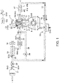
- Figs. 1 and 2 are diagrams illustrating a suitable embodiment of an engine, particular, a compression-ignition engine (hereinafter, simply referred to as “the engine”) to which a control device of the present disclosure is applied.
- the engine illustrated in Figs. 1 and 2 is particularly a four-cycle gasoline direct-injection engine mounted on a vehicle as a drive source for traveling, and includes an engine body 1, an intake passage 30 through which intake air to be introduced into the engine body 1 flows, an exhaust passage 40 through which exhaust gas discharged from the engine body 1 flows, and an exhaust gas recirculation (EGR) device 50 which recirculates a portion of the exhaust gas flowing through the exhaust passage 40 to the intake passage 30.
- EGR exhaust gas recirculation
- the engine body 1 has a cylinder block 3 formed therein with cylinders 2, a cylinder head 4 attached to an upper surface of the cylinder block 3 so as to cover above the cylinders 2, and a piston 5 reciprocatably fitted into each cylinder 2.
- the engine body 1 is of a multi-cylinder type having a plurality of cylinders (e.g., two, three, four, five, six, eight, ten or twelve cylinders).
- the description is only given regarding one cylinder 2 for the sake of simplicity.
- a combustion chamber 6 is defined above the piston 5, and fuel containing gasoline as a main component is injected into the combustion chamber 6 by an injector 15 (described later). Further, the supplied fuel is combusted while being mixed with air in the combustion chamber 6, and expansion force caused by this combustion pushes down the piston 5 and thus it reciprocates in up-and-down directions of the cylinder.
- the fuel injected into the combustion chamber 6 may be any fuel as long as it contains gasoline as a main component and, for example, it may contain a subcomponent, such as bioethanol, in addition to gasoline.
- the crankshaft 7 is connected to the piston 5 via a connecting rod 8 and rotates about its center axis according to the reciprocation (up-and-down motion) of the piston 5.
- a geometric compression ratio of the cylinder 2 that is, a ratio of the volume of the combustion chamber 6 when the piston 5 is at a top dead center (TDC) with the volume of the combustion chamber 6 when the piston 5 is at a bottom dead center (BDC), is set particularly between 13:1 and 30:1 as a suitable value for SPCCI (Spark Controlled Compression Ignition) combustion (partial compression-ignition combustion) described later. More specifically, the geometric compression ratio of the cylinder 2 is set particularly between 14:1 and 17:1 in regular specifications using gasoline fuel having an octane number of about 91, and particularly between 15:1 and 18:1 in high-octane specifications using gasoline fuel having an octane number of about 96.
- the cylinder block 3 is provided with a crank angle sensor SN1 which detects a rotational angle of the crankshaft 7 (crank angle) and a rotational speed of the crankshaft 7 (engine speed).
- the cylinder head 4 is formed with an intake port 9 and an exhaust port 10 which open into the combustion chamber 6, and provided with an intake valve 11 which opens and closes the intake port 9, and an exhaust valve 12 which opens and closes the exhaust port 10.
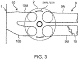
- the type of valve of the engine of this embodiment is a four-valve type including two intake valves and two exhaust valves. That is, the intake port 9 includes a first intake port 9A and a second intake port 9B, and the exhaust port 10 includes a first exhaust port 10A and a second exhaust port 10B. A total of two intake valves 11 are provided so as to open and close the first and second intake ports 9A and 9B, respectively, and a total of two exhaust valves 12 are provided so as to open and close the first and second exhaust ports 10A and 10B, respectively.
- a swirl valve 18 openable and closable of the second intake port 9B is provided therein.
- the swirl valve 18 is only provided in the second intake port 9B, and not provided in the first intake port 9A.
- a circling flow circling around an axial line of the cylinder i.e., swirl flow
- driving the swirl valve 18 in the opening direction weakens the swirl flow.
- the intake port 9 of this embodiment is a tumble port formable of a tumble flow. Therefore, the swirl flow formed when closing the swirl valve 18 is an inclined swirl flow mixed with the tumble flow.
- the intake valve 11 and the exhaust valve 12 are driven to open and close in conjunction with the rotation of the crankshaft 7 by valve operating mechanisms 13 and 14 including a pair of camshafts disposed in the cylinder head 4.
- the valve operating mechanism 13 for the intake valve 11 is built therein with an intake VVT (Variable Valve Timing) 13a changeable of at least an open timing, or an open crank angle, of the intake valve 11.
- the valve operating mechanism 14 for the exhaust valve 12 is built therein with an exhaust VVT 14a changeable of at least a close timing, or a close crank angle, of the exhaust valve 12.
- the intake VVT 13a (exhaust VVT 14a) may be a variable mechanism which changes only the open timing (close timing) while fixing the close timing (open timing) of the intake valve 11 (exhaust valve 12), or a phase-variable mechanism which simultaneously changes the open timing and the close timing of the intake valve 11 (exhaust valve 12).
- the cylinder head 4 is provided with the injector 15 which injects the fuel (mainly gasoline) into the combustion chamber 6, and a spark plug 16 which ignites the mixture gas containing the fuel injected into the combustion chamber 6 from the injector 15 and air introduced into the combustion chamber 6.
- the cylinder head 4 is further provided with an in-cylinder pressure sensor SN2 which detects pressure of the combustion chamber 6 (hereinafter, also referred to as "in-cylinder pressure"). Note that the in-cylinder pressure sensor SN2 corresponds to a "detector.”
- a cavity 20 is formed by denting a relatively wide area of the piston 5, including a center part thereof, to the opposite side from the cylinder head 4 (downward).
- a center section of the cavity 20 is formed with a bulge portion 20a having a substantially conical shape, bulging relatively upward, and both sides of the cavity 20 over the bulge portion 20a in radial directions respectively form a bowl-shaped recessed portion in cross section.
- the cavity 20 is a recessed portion having a donut shape in plan view, formed to surround the bulge portion 20a.
- a section of the crown surface of the piston 5 radially outward of the cavity 20 is a squish portion 21 comprised of an annular flat surface.
- the injector 15 is a multi-port injector having a plurality of nozzle ports at its tip portion, and the fuel is injected radially from the plurality of nozzle ports ("F" in Fig. 2 indicates fuel spray injected from the respective nozzle ports).
- the injector 15 is provided so that its tip portion opposes to the center portion (bulge portion 20a) of the crown surface of the piston 5.
- the spark plug 16 is disposed at a somewhat offset position to the intake side with respect to the injector 15.
- the tip portion (electrode portion) of the spark plug 16 is set at a position overlapping with the cavity 20 in the plan view.
- the intake passage 30 is connected to one side surface of the cylinder head 4 to communicate with the intake port 9. Air (fresh air) taken in from an upstream end of the intake passage 30 is introduced into the combustion chamber 6 through the intake passage 30 and the intake port 9.
- an air cleaner 31 which removes foreign matters within the intake air
- a throttle valve 32 which adjusts a flow rate of intake air
- a booster 33 which pumps the intake air while compressing it
- an intercooler 35 which cools the intake air compressed by the booster 33
- a surge tank 36 is provided in order from the upstream side.
- An airflow sensor SN3 which detects the flow rate of intake air
- first and second intake air temperature sensors SN4 and SN6 which detect a temperature of the intake air
- first and second intake air pressure sensors SN5 and SN7 which detect the pressure of the intake air are provided in various parts of the intake passage 30.
- the airflow sensor SN3 and the first intake air temperature sensor SN4 are provided in a portion of the intake passage 30 between the air cleaner 31 and the throttle valve 32, and detect the flow rate and the temperature of the intake air passing through this portion.
- the first intake air pressure sensor SN5 is provided in a portion of the intake passage 30 between the throttle valve 32 and the booster 33 (downstream of a connection port of an EGR passage 51 described later), and detects the pressure of the intake air passing through this portion.
- the second intake air temperature sensor SN6 is provided in a portion of the intake passage 30 between the booster 33 and the intercooler 35, and detects the temperature of intake air passing through this portion.
- the second intake air pressure sensor SN7 is provided in the surge tank 36 and detects the pressure of intake air in the surge tank 36.
- the booster 33 is a mechanical booster (supercharger) mechanically linked to the engine body 1.
- the specific type of the booster 33 is not particularly limited, for example, any of known boosters, such as Lysholm type, Roots type, or centrifugal type, may be used as the booster 33.
- An electromagnetic clutch 34 electrically switchable of its operation mode between “engaged” and “disengaged” is provided between the booster 33 and the engine body 1.
- a driving force is transmitted from the engine body 1 to the booster 33, and boosting by the booster 33 is performed.
- the electromagnetic clutch 34 is disengaged, the transmission of the driving force is interrupted, and the boosting by the booster 33 is stopped.
- a bypass passage 38 which bypasses the booster 33 is provided in the intake passage 30.
- the bypass passage 38 connects the surge tank 36 to the EGR passage 51 described later.
- a bypass valve 39 is provided in the bypass passage 38.
- the exhaust passage 40 is connected to the other side surface of the cylinder head 4 so as to communicate with the exhaust port 10. Burned gas (exhaust gas) generated in the combustion chamber 6 is discharged outside through the exhaust port 10 and the exhaust passage 40.
- a catalytic converter 41 is provided in the exhaust passage 40.
- the catalytic converter 41 is built therein with a three-way catalyst 41a which purifies hazardous components (HC, CO and NO x ) contained within the exhaust gas flowing through the exhaust passage 40, and a GPF (gasoline-particulate filter) 41b which captures particulate matter (PM) contained within the exhaust gas.
- a suitable catalyst such as a three-way catalyst or a NO x catalyst, may be added downstream of the catalytic converter 41.
- the EGR device 50 has the EGR passage 51 connecting the exhaust passage 40 to the intake passage 30, and an EGR cooler 52 and an EGR valve 53 provided in the EGR passage 51.
- the EGR passage 51 connects a portion of the exhaust passage 40 downstream of the catalytic converter 41 to a portion of the intake passage 30 between the throttle valve 32 and the booster 33.
- the EGR cooler 52 cools the exhaust gas recirculated from the exhaust passage 40 to the intake passage 30 through the EGR passage 51 (external EGR gas) by heat exchange.
- the EGR valve 53 is provided in the EGR passage 51 downstream of the EGR cooler 52 (the side closer to the intake passage 30), and adjusts a flow rate of the exhaust gas flowing through the EGR passage 51.
- a pressure difference sensor SN8 which detects a difference between pressure upstream of the EGR valve 53 and pressure downstream thereof is provided in the EGR passage 51.
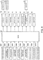
- Fig. 4 is a block diagram illustrating a control system of the engine.
- An ECU (electronic control unit) 100 illustrated in Fig. 4 is a microprocessor which comprehensively controls the engine, and comprised of a well-known processor, ROM, RAM, etc.
- the ECU 100 receives detection signals from various sensors.
- the ECU 100 is electrically connected to the crank angle sensor SN1, the in-cylinder pressure sensor SN2, the airflow sensor SN3, the first and second intake air temperature sensors SN4 and SN6, the first and second intake air pressure sensors SN5 and SN7, and the pressure difference sensor SN8, which are described above.
- the ECU 100 sequentially receives the information detected by these sensors (i.e., the crank angle, the engine speed, the in-cylinder pressure, the intake air flow rate, the intake air temperatures, the intake air pressures, the difference in pressure between the upstream and downstream sides of the EGR valve 53, etc.).
- an accelerator sensor SN9 which detects an opening of an accelerator pedal controlled by a vehicle driver driving the vehicle and a vehicle speed sensor SN10 which detects a traveling speed of the vehicle (hereinafter, referred to as “the vehicle speed") are provided in the vehicle, and detection signals from the accelerator sensor SN9 and the vehicle speed sensor SN10 are also inputted to the ECU 100.
- the ECU 100 controls various components of the engine while executing various determinations and calculations based on the input signals from the various sensors. That is, the ECU 100 is electrically connected to the intake VVT 13a, the exhaust VVT 14a, the injector 15, the spark plug 16, the swirl valve 18, the throttle valve 32, the electromagnetic clutch 34, the bypass valve 39, the EGR valve 53, etc., and outputs control signals to these components based on various calculation results.
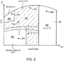
- Fig. 5 is a map illustrating a difference in control according to speed/load of the engine.
- an operating range of the engine are roughly divided by a difference in combustion modes into four operating ranges, a first operating range A1, a second operating range A2, a third operating range A3, and a fourth operating range A4.
- the first operating range A1 is a low-speed low-load range in which the engine speed and load are both low.
- the third operating range A3 is a low-speed high-load range in which the engine speed is low and the load is high.
- the fourth operating range A4 is a high-speed range in which the engine speed is high.
- the second operating range A2 is a remaining range except for the first, third and fourth ranges A1, A3 and A4 (i.e., a range in which a low-speed medium-load range and a medium-speed range are combined).
- the combustion mode, etc. selected in each operating range is sequentially described.
- the partial compression-ignition combustion combined the SI combustion and the CI combustion (hereinafter referred to as "SPCCI combustion") is performed.
- the SI combustion is a mode in which the mixture gas is ignited by the spark plug 16 and is then forcibly combusted by flame propagation which spreads the combusting region from the ignition point
- the CI combustion is a mode in which the mixture gas is combusted by self-ignition in an environment increased in temperature and pressure due to the compression of the piston 5.
- the SPCCI combustion combining the SI combustion and the CI combustion is a combustion mode in which the SI combustion is performed on a portion of the mixture gas inside the combustion chamber 6 by the spark-ignition performed in an environment immediately before the mixture gas self-ignites, and after the SI combustion, the CI combustion is performed on the remaining mixture gas in the combustion chamber 6 by self-ignition (by the further increase in temperature and pressure accompanying the SI combustion).
- SPCCI is an abbreviation of "SPark Controlled Compression Ignition.”
- the SPCCI combustion has a characteristic that the heat generation in the CI combustion is faster than that in the SI combustion.
- a waveform of a heat generation rate caused by the SPCCI combustion has a shape in which a rising slope in an early stage of the combustion which corresponds to the SI combustion is gentler than a rising slope caused corresponding to the CI combustion occurring subsequently.
- the waveform of the heat generation rate caused by the SPCCI combustion is formed to have a first heat generation rate portion formed by the SI combustion and having a relatively gentle rising slope, and a second heat generation rate portion formed by the CI combustion and having a relatively sharp rising slope, which are next to each other in this order.
- a pressure increase rate (dp/d ⁇ ) inside the combustion chamber 6 caused by the SI combustion is lower than that in the CI combustion.
- the slope of the waveform of the heat generation rate changes from gentle to sharp at the timing of self-ignition (that is, the timing, or the crank angle, when the CI combustion starts). That is, the waveform of the heat generation rate caused by the SPCCI combustion has a flection point at a timing when the CI combustion starts (labeled with an "X" in Fig. 7 ).
- the SI combustion and the CI combustion are performed in parallel.
- the heat generation rate becomes relatively high.
- CTDC compression stroke
- the slope of the waveform of the heat generation rate does not become excessive. That is, after CTDC, since the motoring pressure decreases due to the piston 5 descending, the rise of the heat generation rate is prevented, which avoids excessive dp/d ⁇ in the CI combustion.
- the SPCCI combustion ends as the CI combustion finishes. Since the combustion speed of the CI combustion is faster than that of the SI combustion, the combustion end timing is advanced compared to performing the SI combustion alone (in the case where the SI combustion is performed on all the fuel). In other words, the SPCCI combustion brings the combustion end timing closer to CTDC, on the expansion stroke. Thus, the SPCCI combustion improves the fuel efficiency compared to the SI combustion alone.
- the various components of the engine are controlled by the ECU 100 as follows.
- the injector 15 injects all or majority of the fuel to be injected for one combustion cycle, during the compression stroke. For example, at an operation point P1 within the first operating range A1, the injector 15 injects the fuel separately in two times from an intermediate stage to a final stage of the compression stroke, as illustrated in the chart (a) of Fig. 6 .
- the spark plug 16 ignites the mixture gas near CTDC. For example, at the operation point P1, the spark plug 16 ignites the mixture gas at a slightly advanced timing from CTDC. This ignition triggers the SPCCI combustion, a portion of the mixture gas in the combustion chamber 6 is combusted through flame propagation (SI combustion), and then the rest of the mixture gas is combusted by self-ignition (CI combustion).
- SI combustion flame propagation
- CI combustion self-ignition
- the booster 33 is controlled to be OFF. That is, the electromagnetic clutch 34 is disengaged to disconnect the booster 33 from the engine body 1 and the bypass valve 39 is fully opened so as to stop boosting by the booster 33.
- the intake VVT 13a and the exhaust VVT 14a set valve operation timings of the intake and exhaust valves 11 and 12 so that internal EGR is performed, i.e., the valve overlap period in which both the intake and exhaust valves 11 and 12 are opened over TDC of the exhaust stroke is sufficiently formed.
- the internal EGR which leaves the burned gas inside the combustion chamber 6 is achieved, and the temperature of the combustion chamber 6 (the initial temperature before the compression) is increased.
- the throttle valve 32 is fully opened.
- An opening of the EGR valve 53 is controlled so that an air-fuel ratio (A/F), which is a mass ratio between air (fresh air) in the combustion chamber 6 and the fuel, becomes a given target air-fuel ratio.
- A/F air-fuel ratio
- the target air-fuel ratio in the first operating range A1 is set leaner ( ⁇ >1) than a stoichiometric air-fuel ratio on the lower load side of a load line L illustrated in Fig. 5 , and set to or near the stoichiometric air-fuel ratio ( ⁇ 1) on the higher load side of the load line L.
- ⁇ is an excess air ratio.
- the EGR valve 53 adjusts an amount of the exhaust gas recirculated through the EGR passage 51 (external EGR gas) so that the amount of air (fresh air) corresponding to the target air-fuel ratio described above is introduced into the combustion chamber 6.
- the EGR valve 53 adjusts the flow rate in the EGR passage 51 so as to recirculate from the EGR passage 51 to the combustion chamber 6, an amount of gas obtained by subtracting the air amount corresponding to the target air-fuel ratio and the amount of burned gas left in the combustion chamber 6 due to the internal EGR from a total gas amount introduced into the combustion chamber 6 in the state where the throttle valve 32 is fully opened, as external EGR gas.
- the air-fuel ratio (A/F) is set to or leaner than the stoichiometric air-fuel ratio as described above, and also the EGR gas (external EGR gas and internal EGR gas) is introduced into the combustion chamber 6. Therefore, a gas-fuel ratio (G/F) which is a mass ratio of the total gas to the fuel in the combustion chamber 6 is lean over the entire first operating range A1.
- An opening of the swirl valve 18 is in the fully closed state or narrowed to a small opening close to the fully closed state.
- all or majority of the intake air introduced into the combustion chamber 6 is from the first intake port 9A (the intake port on the side where the swirl valve 18 is not provided), thus a strong swirl flow is formed inside the combustion chamber 6.
- This swirl flow grows during the intake stroke and remains until the middle of the compression stroke. Therefore, for example, when the fuel is injected after an intermediate stage of the compression stroke as at the operation point P1 described above, stratification of the fuel is achieved by the effect of the swirl flow.
- the air-fuel ratio in the center portion of the combustion chamber 6 is set to particularly between 20:1 and 30:1 and the air-fuel ratio in an outer circumference portion of the combustion chamber 6 is set to particularly 35:1 or above.
- the control for performing the SPCCI combustion of the mixture gas while the booster 33 performs the boosting is executed.
- various components of the engine are controlled by the ECU 100 as follows.
- the injector 15 injects a portion of the fuel to be injected in one combustion cycle during the intake stroke, and injects the rest of the fuel on the compression stroke. For example, as illustrated in the chart (b) of Fig. 6 , at an operation point P2 within the second operating range A2, the injector 15 performs a first (first-time) fuel injection by which a relatively large amount of fuel is injected during the intake stroke and performs a second (second-time) fuel injection by which a smaller amount of fuel than the first fuel injection is injected during the compression stroke. Further, as illustrated in the chart (c) of Fig. 6 , at an operation point P3 which is on the higher load and higher speed side of the operation point P2, the injector 15 performs a fuel injection over a series of period from the intake stroke to the compression stroke.
- the spark plug 16 ignites the mixture gas near CTDC.
- the spark plug 16 ignites the mixture gas at a slightly advanced timing from CTDC at the operation point P2 (the chart (b) of Fig. 6 ) and ignites the mixture gas at a slightly retarded timing from CTDC at the operation point P3 (the chart (c) of Fig. 6 ).
- This ignition triggers the SPCCI combustion, a portion of the mixture gas inside the combustion chamber 6 is combusted through flame propagation (SI combustion), and then the rest of the mixture gas is combusted by self-ignition (CI combustion).
- SI combustion flame propagation
- CI combustion self-ignition
- the booster 33 is turned on. That is, the electromagnetic clutch 34 is engaged to connect the booster 33 to the engine body 1 so as to perform the boosting by the booster 33.
- the opening of the bypass valve 39 is controlled so that the pressure in the surge tank 36 (boosting pressure) detected by the second intake air pressure sensor SN7 matches a given target pressure determined in advance for each operating condition (engine speed and engine load). For example, as the opening of the bypass valve 39 increases, the flow rate of the intake air which flows back to the upstream side of the booster 33 through the bypass passage 38 increases, and as a result, the pressure of the intake air introduced into the surge tank 36, i.e., the boosting pressure, becomes low. By adjusting the backflow amount of the intake air in this manner, the bypass valve 39 controls the boosting pressure to the target pressure.
- the intake VVT 13a and the exhaust VVT 14a set valve operation timings of the intake and exhaust valves 11 and 12 so that the internal EGR is performable only in a portion of the second operating range A2 on the lower load side (i.e., so that the internal EGR is stopped on the higher load side).
- the throttle valve 32 is fully opened.
- the opening of the EGR valve 53 is controlled so that the air-fuel ratio (A/F) in the combustion chamber 6 becomes the target air-fuel ratio.
- the target air-fuel ratio in the second operating range A2 is set to lean ( ⁇ >1) on the lower load side of the load line L ( Fig. 5 ), and set to or near the stoichiometric air-fuel ratio ( ⁇ 1) on the higher load side of the load line L.
- the EGR valve 53 adjusts the amount of the external gas recirculated through the EGR passage 51 (external EGR gas) so that the air (fresh air) amount corresponding to the target air-fuel ratio is introduced into the combustion chamber 6.
- the recirculation amount of the exhaust gas is adjusted to be smaller as approaching the higher load side, and adjusted to approximately zero near the highest load of the engine.
- the gas-fuel ratio (G/F) inside the combustion chamber 6 is set lean except for near the highest load of the engine.
- the opening of the swirl valve 18 is in the fully closed state or opened to a suitable medium opening except for the full open state.
- the opening of the swirl valve 18 is in the fully closed state in the low load side portion of the second operating range A2 and in the medium opening in the remaining high load side. Note that the medium opening of the swirl valve 18 increases as the load increases.
- a control is executed in which at least a portion of the fuel is injected in the final stage of the compression stroke and the mixture gas is subjected to the SI combustion.
- the various components of the engine are controlled by the ECU 100 as follows.
- the injector 15 injects a portion of the fuel to be injected in one combustion cycle during the intake stroke, and injects the rest of the fuel in a final stage of the compression stroke. For example, as illustrated in the chart (d) of Fig. 6 , at an operation point P4 within the third operating range A3, the injector 15 performs the first fuel injection in which a relatively large amount of fuel is injected during the intake stroke and performs the second fuel injection in which a smaller amount of fuel than the first fuel injection is injected in the final stage of the compression stroke (immediately before CTDC).
- the spark plug 16 ignites the mixture gas at a relatively retarded timing, for example 5°CA to 20°CA from CTDC. Further, this ignition triggers the SI combustion, and all of the mixture gas in the combustion chamber 6 combusts through flame propagation.
- a relatively retarded timing for example 5°CA to 20°CA from CTDC.
- this ignition triggers the SI combustion, and all of the mixture gas in the combustion chamber 6 combusts through flame propagation.
- the reason why the ignition timing within the third operating range A3 is retarded as described above is to prevent abnormal combustion, such as knocking and pre-ignition.
- the second fuel injection is set to be performed in the final stage of the compression stroke (immediately before CTDC), which is considerably late, therefore, even with the ignition timing retarded as described above, the combustion speed after the ignition (flame propagation speed) is relatively fast.
- the booster 33 is controlled to be ON. That is, the electromagnetic clutch 34 is engaged to connect the booster 33 to the engine body 1 so as to perform the boosting by the booster 33.
- the opening of the bypass valve 39 is controlled so that the pressure inside the surge tank 36 (the boosting pressure) matches the target pressure.
- the throttle valve 32 is fully opened.
- the opening of the EGR valve 53 is controlled so that the air-fuel ratio (A/F) in the combustion chamber 6 becomes the stoichiometric air-fuel ratio or slightly richer than the stoichiometric air-fuel ratio.
- the gas-fuel ratio (G/F) inside the combustion chamber 6 is set lean except for near the highest load of the engine.
- the opening of the swirl valve 18 is set to or near a given intermediate opening (e.g., 50%).
- a fourth operating range A4 on the higher speed side of the first to third ranges A1 to A3 relatively basic SI combustion is executed.
- the various components of the engine are controlled by the ECU 100 as follows.
- the injector 15 at least injects the fuel over a given period overlapping with the intake stroke. For example, at an operation point P5 within the fourth operating range A4, the injector 15 injects the fuel over a continuous period from the intake stroke to the compression stroke, as illustrated in the chart (e) of Fig. 6 . Note that at the operation point P5, since it corresponds to a considerably high-speed and high-load condition, the amount of fuel to be injected in one combustion cycle is large and also a crank angle period required for injecting the required amount of fuel becomes long, for which the fuel injection period at the operation point P5 is longer than the other operation points (P1 to P4) described above.
- the spark plug 16 ignites the mixture gas near CTDC. For example, at the operation point P5, the spark plug 16 ignites the mixture gas at a slightly advanced timing from CTDC. Further, this ignition triggers the SI combustion, and all the mixture gas in the combustion chamber 6 combusts through flame propagation.
- the booster 33 is controlled to be ON and performs boosting.
- the boosting pressure here is adjusted by the bypass valve 39.
- the throttle valve 32 is fully opened.
- the opening of the EGR valve 53 is controlled so that the air-fuel ratio (A/F) in the combustion chamber 6 becomes the stoichiometric air-fuel ratio or slightly richer.
- the gas-fuel ratio (G/F) inside the combustion chamber 6 is set lean except for near the highest load of the engine.
- the swirl valve 18 is fully opened. Thus, not only the first intake port 9A but also the second intake port 9B are fully opened and charging efficiency of the engine is improved.
- the SPCCI combustion combined the SI combustion and the CI combustion is performed within the first and second operating ranges A1 and A2.
- an SI ratio which is a ratio of a heat generation amount by the SI combustion to the total heat generation amount by the SPCCI combustion (the SI combustion and the CI combustion) is used.
- Fig. 7 is a chart illustrating this SI ratio and illustrating a change in the heat generation rate (J/deg) according to the crank angle when the SPCCI combustion occurs.
- the flection point X in the waveform of Fig. 7 is a flection point appearing when the combustion mode switches from the SI combustion to the CI combustion and the crank angle ⁇ ci corresponding to this flection point X may be defined as the start timing of CI combustion.
- an area R1 of the waveform of the heat generation rate located on the advance side of this ⁇ ci (the start timing of CI combustion) is set as the heat generation amount by the SI combustion
- an area R2 of the waveform of the heat generation rate located on the retarding side of ⁇ ci is set as the heat generation rate by the CI combustion.
- the SI ratio is in correlation with a combustion center of gravity which is a timing or a crank angle when substantially a half of the total mass (50% mass) of the fuel injected into the combustion chamber 6 in one combustion cycle combusts.
- a combustion center of gravity which is a timing or a crank angle when substantially a half of the total mass (50% mass) of the fuel injected into the combustion chamber 6 in one combustion cycle combusts.
- an optimal combustion center of gravity at which high thermal efficiency is obtained while having combustion noise at an allowable level or lower is determined as a target combustion center of gravity in advance and an optimal SI ratio corresponding to the target combustion center of gravity is determined as a target SI ratio in advance.
- the target combustion center of gravity changes according to the operating condition (speed/load) of the engine.
- the operating condition speed/load
- the combustion center of gravity needs to be greatly retarded from CTDC in order to reduce combustion noise.
- the heat generation amount is small and combustion noise does not easily increase. Therefore, it is desirable to set the combustion center of gravity to the advancing side in order to improve thermal efficiency.
- the target combustion center of gravity is comprehensively set further on the retarding side as the engine load is higher (i.e., further on the advancing side as the engine load is lower). Further, since the progression amount of crank angle per unit time changes according to the engine speed, the optimal combustion center of gravity taking the noise and thermal efficiency into consideration also changes according to the engine speed. Therefore, the target combustion center of gravity is set variably also in accordance with the engine speed in addition to the engine load.
- the target SI ratio is also set variably according to the engine speed and engine load. For example, since the target combustion center of gravity is set further on the retarding side as the engine load is higher as described above, the target SI ratio is set higher as the engine load is higher (i.e., the ratio of the CI combustion decreases as the engine load increases).
- target values of control amounts such as the ignition timing of the spark plug 16, the fuel injection amount/timing, and in-cylinder state functions, are determined in advance according to the respective operating conditions (engine speed/load) so that the target combustion center of gravity and the target SI ratio which are set as described above are achieved.
- the in-cylinder state functions referred to here include, for example, the temperature in the combustion chamber 6 and an EGR ratio.
- the EGR ratio includes an external EGR ratio which is a ratio of the external EGR gas (exhaust gas recirculated to the combustion chamber 6 through the EGR passage 51) to all the gas in the combustion chamber 6, and an internal EGR ratio which is a ratio of the internal EGR gas (burned gas remaining in the combustion chamber 6) to all the gas in the combustion chamber 6.
- the ignition timing (the timing, or the crank angle, of spark-ignition) of the spark plug 16 is advanced, a larger amount of fuel is combusted in the SI combustion, and the SI ratio increases.
- the injection timing of the fuel is advanced, a larger amount of fuel is combusted in the CI combustion, and the SI ratio decreases.
- the temperature of the combustion chamber 6 rises, a larger amount of fuel is combusted in the CI combustion, and the SI ratio decreases.
- changes in these control amounts are factors for adjusting the combustion center of gravity.
- the target values of the ignition timing, the fuel injection amount and timing, and the in-cylinder state functions are determined in advance for each operating condition so as to achieve a combination of values achievable of the target combustion center of gravity and the target SI ratio described above.
- the ECU 100 controls the injector 15, the spark plug 16, the EGR valve 53, the intake and exhaust WTs 13a and 14a, etc. based on the target values of these control amounts.
- the spark plug 16 is controlled based on the target value of the ignition timing and the injector 15 is controlled based on the target values of the fuel injection amount and timing.
- the EGR valve 53 and the intake and exhaust WTs 13a and 14a are controlled based on the respective target values of the temperature of the combustion chamber 6 and the EGR ratio, and the recirculation amount of exhaust gas (external EGR gas) through the EGR passage 51 and the residual amount of burned gas (internal EGR gas) by the internal EGR are adjusted.
- the start timing ⁇ ci of the CI combustion when the combustion conforming to the target combustion center of gravity and the target SI ratio is performed is also necessarily determined in advance.
- the start timing of CI combustion determined based on the target combustion center of gravity and the target SI ratio is referred to as standard ⁇ ci.
- This standard ⁇ ci serves as a reference for determining a target ⁇ ci in a flowchart (S4 in Fig. 8 ) described later.
- the SI knock means a phenomenon in which the unburned gas outside the area where the SI combustion of the mixture gas occurs combusts rapidly by abnormal, local self-ignition (local self-ignition which is clearly different from normal CI combustion), and the CI knock is a phenomenon in which main components of the engine (cylinder block/head, piston, crank journal part, etc.) resonate due to a pressure fluctuation by the CI combustion.
- the SI knock occurs as loud noise at a frequency of approximately 6.3 kHz due to vibration of air column inside the combustion chamber 6 occurring by the local self-ignition.
- the CI knock occurs as loud noise at a frequency within a range of approximately 1 to 4 kHz (more specifically, a plurality of frequencies included in this range) due to the resonance of the main components of the engine.
- the SI knock and the CI knock occur as noises at different frequencies caused by different reasons, and the frequency of the noise in the CI knock is lower than the frequency of the noise in the SI knock.
- the SPCCI combustion is controlled so that the SI knock and the CI knock are both reduced.
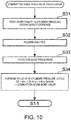
- the level of noise caused by the CI knock (noise of a frequency of approximately 1 to 4 kHz) is detected as a combustion noise index value, and the SPCCI combustion is controlled based on this combustion noise index value.
- the combustion noise index value is calculated particularly by performing a Fourier transform on a detected waveform by the in-cylinder pressure sensor SN2.
- Fig. 8 is a flowchart illustrating a specific procedure of the control executed by the ECU 100 in the SPCCI combustion, that is, in the operation within the first and second operating ranges A1 and A2 illustrated in Fig. 5 .
- the ECU 100 determines the fuel injection amount from the injector 15 and its injection timing, or crank angle, based on the engine speed detected by the crank angle sensor SN1 and the engine load which is specified by the detection value of the accelerator sensor SN9 (accelerator opening), the detection value of the airflow sensor SN3 (intake flow rate), etc.
- the target combustion center of gravity and the target SI ratio are determined in advance for each operating condition of the engine, and the fuel injection amount and timing for achieving the target combustion center of gravity and the target SI ratio are determined in advance for each operating condition of the engine.
- the fuel injection amount and timing determined at S1 is the injection amount and timing for achieving the target combustion center of gravity and the target SI ratio.
- the ECU 100 shifts to S2 to determine a reference value W which is an upper limit of the combustion noise index value allowable under the current operating condition ( Fig. 11 ).
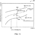
- the ECU 100 specifies the reference value W of the combustion noise index value based particularly on the engine load specified based on the detection value of the accelerator sensor SN9 (accelerator opening), etc., the vehicle speed detected by the vehicle speed sensor SN10, and a map M1 illustrated in Fig. 11 .
- the map M1 of Fig. 11 is a map in which the reference value of the combustion noise index value is defined for each vehicle speed/engine load and stored in the ECU 100 in advance.
- the map M1 includes a first characteristic Q1 defining a reference value W1 when the vehicle speed is changed while the engine load is fixed to a given low load (e.g., a close value to the load corresponding to the operation point P1 illustrated in Fig. 5 ), and a second characteristic Q2 defining a reference value W2 when the vehicle speed is changed while fixing the engine load to a given high load (e.g., a close value to the load corresponding to the operation point P3 illustrated in Fig. 5 ).
- the reference value W2 defined by the second characteristic Q2 for high load is set to be larger than the reference value W1 defined by the first characteristic Q1 for low load. Further, both the first characteristic Q1 and the second characteristic Q2 have a tendency in which the reference values W1 and W2 respectively rise as the vehicle speed increases.
- the first characteristic Q1 for low load has a non-linear characteristic in which a change rate of the reference value W1 within a vehicle speed range below a given value V0 (low vehicle speed range) is higher than that within a range including the given value V0 and higher (high vehicle speed range).
- the ECU 100 identifies the reference value W of the combustion noise index value corresponding to the current operating condition by comparing the current vehicle speed and the engine load (current operating condition) identified based on the detection values of the sensors SN9 and SN10, etc. to the map M1 of Fig. 11 .
- the ECU 100 identifies the reference value W1 corresponding to the current vehicle speed based on a value on the first characteristic Q1 for low load, identifies the reference value W2 corresponding to the current vehicle speed based on a value on the second characteristic Q2 for high load, and identifies the reference value W corresponding to the current operation condition by linear interpolation using the two reference values W1 and W2.
- the current engine load is an intermediate value between the load corresponding to the first characteristic Q1 and the load corresponding to the second characteristic Q2
- an intermediate value between the reference value W1 and the reference value W2 is identified as the reference value W corresponding to the current operating condition.
- a value lower than the reference value W1 is identified as the reference value W corresponding to the current operating condition. Note that it is needless to say that when the current engine load matches with the load corresponding to the first characteristic Q1 (or the second characteristic Q2), the reference value W1 (or W2) is identified as it is as the reference value W corresponding to the current operation condition.
- the reference value W is set larger as the vehicle speed and/ or engine load increases.
- the reference value W is set larger as the vehicle speed/engine load increases. That is, the reference value W is a value which becomes larger when either one of the vehicle speed and engine load increases, becomes the smallest when both of the vehicle speed and engine load are low, and becomes the largest when both of the vehicle speed and engine load are high. This is because even if the combustion sound is small, it is perceived more easily as the vehicle speed and load are lower (conversely, even if the combustion sound is large, it is difficult to be perceived when the vehicle speed and load are high).
- the ECU 100 shifts to S3 to determine as the final reference value Wx of the combustion noise index value, a value obtained by subtracting from the reference value W of the combustion noise index value corresponding to the current operating condition specified at S2, a margin y which is based on a variation of the combustion noise index value acquired previously.
- the margin y which is subtracted from the reference value W in the above processing is obtained from a history of the combustion noise index value acquired previously (S11 described later), and corresponds to a standard deviation of combustion noise index values accumulated in the past over a given period.
- the final reference value Wx is determined in consideration of the variation (standard deviation) in the combustion noise index value as described above because, if the same reference value is selected in disregard of the variation in noise in each combustion cycle, a possibility that the combustion accompanied by loud noise exceeding the reference value incidentally occurs becomes high.
- the final reference value Wx is set in consideration of the variation (e.g., standard deviation) in the above manner so as to ensure that combustion accompanied by loud noise exceeding the reference value does not occur in any combustion cycle regardless of the degree of the variation in the noise.
- the ECU 100 shifts to S4 to determine the target ⁇ ci which is a target start timing, or a target start crank angle, of the CI combustion.
- This target ⁇ ci is a target value of the crank angle (the crank angle ⁇ ci illustrated in Fig. 7 ) at which the SI combustion is switched to the CI combustion, and is determined so as to make the combustion noise index value below the final reference value Wx.
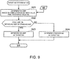
- Fig. 9 is a subroutine illustrating details of a control at S4 where the target ⁇ ci is determined.
- the ECU 100 determines a ⁇ ci limit which is a limit of the start timing of the CI combustion by which the noise index value is made equal to or lower than the final reference value Wx, based on the engine speed detected by the crank angle sensor SN1, the engine load specified based on the detection value of the accelerator sensor SN9, etc., the final reference value Wx of the combustion noise index value determined at S3, and a map M2 illustrated in Fig. 12 .
- the map M2 of Fig. 12 is a map defining a standard relationship between ⁇ ci (the start timing of the CI combustion) and the combustion noise index value, and is stored in the ECU 100 in advance. More specifically, the map M2 defines a standard characteristic of the combustion noise index value obtained when the engine load is variously changed while keeping the engine speed (N1), and the horizontal axis indicates ⁇ ci and the vertical axis indicates the combustion noise index value (estimated value). Note that although in Fig. 12 , only three types of loads, the low load, the medium load, and the high load are illustrated for the sake of convenience, the characteristics other than the three types of loads are also included in the map M2.
- the combustion noise index value may be estimated by, for example, linear interpolation. As described above, in this embodiment, when ⁇ ci is changed under various conditions with different engine speeds/loads, how the combustion noise index value changes accordingly is estimated using the map M2 of Fig. 12 .
- the ECU 100 compares the final reference value Wx of the combustion noise index value determined at S3 with the map M2 in Fig. 12 to specify ⁇ ci so that the combustion noise index value matches with the final reference value Wx, and this ⁇ ci is determined as the ⁇ ci limit described above.
- the ECU 100 shifts to S22 to determine whether the ⁇ ci limit determined at S21 is on the retarding side of a given standard ⁇ ci.
- the standard ⁇ ci used here is, as described in Section (4) above, the start timing of the CI combustion obtained when the combustion with the target combustion center of gravity and the target SI ratio determined for each operating condition of the engine (in other words, targeted SPCCI combustion) is achieved.
- the ECU 100 shifts to S24 to determine the standard ⁇ ci as the target ⁇ ci.
- the ECU 100 shifts to S5 of Fig. 8 to determine whether the crank angle is at a specific angle based on the detection value of the crank angle sensor SN1.
- This specific crank angle is determined in advance as the timing for determining the ignition timing by the spark plug 16, for example, about 60°CA before CTDC.
- the ECU 100 shifts to S6 to determine an ignition timing for achieving the target ⁇ ci determined at S4.
- the target values of the target combustion center of gravity, the target SI ratio, the standard ⁇ ci corresponding to the target combustion center of gravity and the target SI ratio, the ignition timing for achieving the standard ⁇ ci, the fuel injection amount, the fuel injection timing, and the in-cylinder state functions are determined in advance, and the ignition timing is determined based on these target values.
- the ignition timing for achieving the target ⁇ ci is determined based on a deviation of the standard ⁇ ci from the target ⁇ ci and the in-cylinder state functions at the specific crank angle timing.
- the ignition timing needs to be deviated greater from an initial target value of the ignition timing determined corresponding to the standard ⁇ ci (hereinafter, referred to as "default ignition timing"). Further, as the in-cylinder state functions at the specific crank angle timing deviate greater from the target values, the ignition timing still needs to be deviated greater from the default ignition timing.
- the initial target values are adopted as they are as the fuel injection amount and the fuel injection timing, the deviations of the fuel injection amount and the fuel injection timing are not required to be taken into consideration.
- the ignition timing of the spark plug 16 is determined based on the deviation of the standard ⁇ ci from the target ⁇ ci and the deviation of the in-cylinder state functions from the target value.
- the in-cylinder state functions that is, the temperature of the combustion chamber 6, the EGR ratio, etc. may be estimated based on, for example, the detection values of the second intake air temperature sensor SN6, the second intake air pressure sensor SN7, the pressure difference sensor SN8, etc. Note that when the target ⁇ ci is the same as the standard ⁇ ci and the in-cylinder state functions at the specific crank angle timing is the same as the target value, the default ignition timing is adopted as the ignition timing as it is.
- the ECU 100 shifts to S7 to estimate a combustion center of gravity which is a timing when a half of the mass (50% mass) of the total fuel injected into the combustion chamber 6 in one combustion cycle combusts, based on the fuel injection amount and the fuel injection timing determined at S1, the ignition timing determined at S6, and the in-cylinder state functions at the specific crank angle timing, and the engine speed.
- the estimation processing at S7 is performed based on an estimation model prepared in advance.
- the ECU 100 shifts to S8 to determine a given period including the combustion center of gravity estimated at S7 as a period in which the in-cylinder pressure for calculating the combustion noise index value at S10 described later is detected.
- the period in which the in-cylinder pressure is detected (hereinafter, referred to as "detection period") is determined to be a finite and continuous period including the combustion center of gravity.
- the detection period may be a period set based on time, or may be a period set based on the crank angle. In the case of using the crank angle, for example, a period from the crank angle advancing by 40°CA from the combustion center of gravity to the crank angle retarding by 40°CA therefrom as the detection period (see Fig. 13 described later).
- the ECU 100 shifts to S9 to cause the spark plug 16 to ignite at the ignition timing determined at S6, so as to trigger the SPCCI combustion of the mixture gas.
- the ECU 100 shifts to S10 to calculate the combustion noise index value based on the waveform of the in-cylinder pressure detected by the in-cylinder pressure sensor SN2 during the detection period determined at S8.
- Fig. 10 is a subroutine illustrating details of a control at S10 where the noise index value is calculated.
- the ECU 100 reads the waveform of the in-cylinder pressure detected by the in-cylinder pressure sensor SN2 during the detection period.
- Fig. 13 is a chart illustrating one example of the waveform of the in-cylinder pressure read at S31.
- the crank angle displayed on the horizontal axis of the chart is the crank angle (deg. ATDC) when CTDC is 0°CA.
- the combustion center of gravity is estimated to be around ATDC 20°CA, and a period including 40°CA before and after the combustion center of gravity (a period from ATDC 20°CA to ATDC 60°CA) is set as the detection period.
- the detected waveform within this detection period includes ignition noise which is noise caused by the ignition of the spark plug 16.
- the ECU 100 shifts to S32 to perform Fourier-analysis on a detected waveform of the in-cylinder pressure read at S31 and obtain an amplitude for each frequency component.
- processing of applying a window function for removing the ignition noise is performed on the detected waveform of the in-cylinder pressure.
- a function generally used for Fourier analysis e.g., Hanning window function
- Fig. 14 is a chart illustrating a frequency spectrum obtained by the Fourier analysis performed at S32. Since the ignition noise is removed from the detected waveform by the pre-processing (the application of the window function) in the Fourier analysis as described above, the frequency spectrum obtained by Fourier-analyzing the waveform after the ignition noise removal (solid line) is different from a frequency spectrum obtained in a case where the ignition noise is not removed (dashed line). That is, according to the method of at S32 where the ignition noise is removed and then the Fourier analysis is conducted, unnecessary frequency components caused by the ignition noise do not mix in and the original frequency component in the waveform of the in-cylinder pressure is accurately extracted.
- the 1/3 octave band processing is processing of dividing each octave range (a range from a certain frequency to a frequency twice thereof) of the frequency spectrum into three and calculating an in-cylinder pressure level (CPL) of each divided band.
- CPL in-cylinder pressure level
- the ECU 100 shifts to S34 to calculate the combustion noise index value based on the result of the 1/3 octave band processing ( Fig. 15 ) at S33.
- the ECU 100 calculates, as the noise index value, an average value of in-cylinder pressure levels indicated by diamond shaped plots in Fig. 15 , i.e., the in-cylinder pressure levels of the bands having the center frequencies of 1 kHz, 1.25 kHz, 1.6 kHz, 2 kHz, 2.5 kHz, 3.15 kHz, and 4 kHz.
- the noise having a frequency of 1 to 4 kHz is highly correlated with the CI knock caused by the CI combustion, as described above.
- this noise of 1 to 4 kHz is sufficiently reduced, the SI knock caused by the SI combustion and noise near 6.3 kHz, which is highly correlated with SI knock are also sufficiently reduced.
- the noise of 1 to 4 kHz originally indicates the noise equivalent to about the CI knock, due to the above circumstances, it can be treated as noise indicating that equivalent to both CI knock and SI knock.
- an average value of the in-cylinder pressure levels in the bands of 1 to 4 kHz (1 kHz, 1.25 kHz, ..., 4 kHz) is calculated and used as the combustion noise index value for reducing the CI knock and the SI knock.
- the in-cylinder pressure level in the 6.3 kHz band (labeled as "P" in Fig. 15 ) is not considered as the combustion noise index value.
- the ECU 100 shifts to S11 of Fig. 8 to calculate and update the standard deviation of the combustion noise index value based on the latest combustion noise index value calculated at S34 and the plurality of combustion noise index values accumulated previously.
- the standard deviation updated in this manner is used as the margin y ( Fig. 11 ) when determining the final reference value Wx of the combustion noise index value.
- the standard deviation of the combustion noise index value may be obtained from the combustion noise index values accumulated, for example, over a latest given period or separately for every similar operating condition.
- the ECU 100 shifts to S12 to calculate the combustion center of gravity based on the waveform of the in-cylinder pressure during the detection period and correct the estimation model of the combustion center of gravity based on the calculated combustion center of gravity. That is, the ECU 100 calculates the heat generation amount accompanying the combustion for each crank angle based on the waveform of the in-cylinder pressure detected by the in-cylinder pressure sensor SN2 during the detection period, and the combustion center of gravity at the timing when 50% mass of the fuel combusts is calculated based on the data of the heat generation amount for each crank angle. Further, the estimation model for estimating the combustion center of gravity is corrected based on the deviation between this calculated combustion center of gravity and the combustion center of gravity estimated at S7. The correction of this estimation model leads to improving the accuracy in estimating the combustion center of gravity under the similar condition next time and thereafter (the reduction of the deviation between the estimated value and the actual value).
- the control for adjusting the ignition timing so that the combustion noise index value does not exceed the reference value W, etc. are executed based on the combustion noise index value which is identified based on the in-cylinder pressure detected by the in-cylinder pressure sensor SN2, and the reference value W (more specifically, the final reference value Wx obtained by subtracting the margin y from the reference value W) determined beforehand as the upper limit of the combustion noise index value.
- the reference value W is set higher as the vehicle speed or the engine load increases.
- the reference value W of the combustion noise index value is set higher as the vehicle speed or the engine load increases, and the combustion is controlled based on the reference value W. Therefore, the ratio of the CI combustion is increased as much as possible while keeping the combustion noise which is actually perceived by the passenger to an adequate level.
- Figs. 16A and 16B illustrate that the sound pressure (SPL) of the background noise transmitted into the cabin changes depending on a condition.
- Fig. 16A is a chart illustrating a relationship between the vehicle traveling sound, which is transmitted into the cabin, and the vehicle speed.
- Fig. 16B is a chart illustrating the relationship between the engine sound, which is transmitted into the cabin, and the engine speed for two kinds of engine loads.
- the line chart described as "HIGH LOAD” indicates a change in the engine sound when the engine speed is changed while keeping the engine load at a certain high load.
- the line chart described as "LOW LOAD” indicates a change in the engine sound when the engine speed is changed while keeping the engine load at a certain low load.
- traveling sound of the vehicle illustrated in Fig. 16A is a mixed sound of wind, road noise, etc.
- engine sound illustrated in Fig. 16B is a mixed sound of machines of the engine (e.g., a friction sound of a rotational component), combustion, exhaustion, etc.
- the traveling sound of the vehicle increases as the vehicle speed increases.
- the engine sound increases as a whole as the engine load increases, and while the engine load is fixed, the engine sound increases as the engine speed increases (i.e., as the vehicle speed increases).
- the background noise transmitted into the cabin is the mixture of the traveling sound of the vehicle and the engine sound, based on the result of Figs. 16A and 16B , the background noise can be said to increase when either one of the vehicle speed and the engine load increases. That is, the background noise takes a lowest value when the vehicle speed and the engine load are both low, and takes a highest value when the vehicle speed and the engine load are both high.
- the reference value W of the combustion noise index value is set in proportion to both the vehicle speed and the engine load (to increase as either one of the vehicle speed and the engine load increases) in consideration of the tendency of the background noise described above (the traveling sound of the vehicle and the engine sound).
- the combustion is controlled based on the reference value W set in such a manner, the ratio of the CI combustion is increased as much as possible while keeping the combustion noise which is actually perceived by the passenger (i.e., the combustion noise perceived by the passenger without being mixed with the background sound) to an adequate level.
- the reference value W when the reference value W is set uniformly disregarding the vehicle speed and the engine load, the reference value W needs to be set sufficiently low so that the combustion noise is not easily perceived by the passenger even when the background noise takes the smallest value, i.e., when the vehicle speed is low and the engine is low.
- the combustion is constantly controlled based on the low reference value W, the ratio of the CI combustion may decrease significantly and the fuel efficiency improving effect may drop.
- the ratio of the CI combustion is not lowered excessively (the SI ratio is excessively increased) to reduce the combustion noise more than necessary, while the comfort of the passenger is properly secured, the ratio of the CI combustion is increased as much as possible to effectively improve the fuel efficiency.
- the map M1 for determining the reference value W of the combustion noise index value is prepared including the first characteristic Q1 defining the reference value W1 when the engine load is the fixed low load and the second characteristic Q2 defining the reference value W2 when the engine load is the fixed high load.
- the reference value W corresponding to the current operation condition is identified by the interpolation processing (linear interpolation) using the reference values W1 and W2 defined for the first and second characteristics Q1 and Q2.
- the reference value W1 defined by the first characteristic Q1 for low load is set so that its change rate with respect to the vehicle speed is larger in the vehicle speed range below a given value V0 (low vehicle speed range) than in the vehicle speed range including the given value V0 and higher (high vehicle speed range). Therefore, the suitable reference value W is set in consideration of the characteristic that the engine sound transmitted into the cabin changes non-linearly with respect to the engine speed (or the vehicle speed), and the combustion noise is kept at an adequate level by using the reference value W.
- the engine sound transmitted into the cabin when the engine load is low sharply increases as the engine speed increases especially within a low engine speed range (the section circled by a dash line).
- the change rate (increase rate) of the engine sound with respect to the engine speed increases as the engine speed decreases.
- the target ⁇ ci which is the target start timing of the CI combustion (the switch timing from the SI combustion to the CI combustion), is determined so that the combustion noise index value does not exceed the reference value W, and the ignition timing is controlled to achieve the determined target ⁇ ci. Therefore, by adjusting the target ⁇ ci having a large influence on the combustion noise index value, the ratio of the CI combustion is increased as much as possible while keeping the combustion noise adequately.
- the map M1 including the first characteristic Q1 defining the reference value W1 when the engine load is the fixed low load and the second characteristic Q2 defining the reference value W2 when the engine load is the fixed high load is prepared in advance, and the reference value W of the combustion noise index value conforming to the operating condition at each time point is determined based on the map M1.
- a plurality of independent characteristics corresponding to a gear position of a transmission mounted on the vehicle (1st to 6th ranges in this example) may be prepared for low load and high load, respectively. Note that in the case of the vehicle equipped with six forward ranges as illustrated in Fig. 17 , twelve characteristics including six characteristics for low loads and six characteristics for high loads are prepared.
- two characteristics including the characteristic for low load (the first characteristic Q1) and the characteristic for high load (the second characteristic Q2) are prepared.
- three characteristics of low load, medium load, and high load may be prepared, or four or more characteristics may be prepared.
- the reference value W when the vehicle speed is changed in a plurality of engine load conditions is identified based on the characteristics Q1 and Q2.
- a characteristic defining the change of the reference value W with respect to the engine speed may be prepared.
- the reference value W is naturally set higher as the engine speed is higher. Accordingly, the reference value W is set larger as the vehicle speed, engine speed, and/ or engine load increases.
- the combustion noise index value is specified based on the in-cylinder pressure detected by the in-cylinder pressure sensor SN2 (detector)
- the parameter which needs to be detected in order to specify the combustion noise index value may be any parameter as long as it relates to noise accompanying combustion, and the in-cylinder pressure is merely one example.
- vibration vibration acceleration
- the detector of the present disclosure may use, other than the in-cylinder pressure, a vibration sensor configured to detect the vibration of the engine body 1, a noise sensor configured to detect noise, etc.
- the average value of the in-cylinder pressure levels highly correlated with the CI knock more specifically, the in-cylinder pressure levels of the bands of 1 kHz, 1.25 kHz, 1.6 kHz, 2 kHz, 2.5 kHz, 3.15 kHz, and 4 kHz, which are obtained by Fourier-analyzing the detected waveform of the in-cylinder pressure, is calculated and this average value is used as the combustion noise index value; however, a highest value of the in-cylinder pressure levels in these bands may alternatively be calculated as the noise index value.
- the noise index value may be calculated using only the in-cylinder pressure levels in a limited band closest to each resonance frequency. In other words, the in-cylinder pressure levels in a part of each band far from the resonance frequency may be disregarded.
- the combustion noise index value is not limited to the value obtained based on the in-cylinder pressure levels of the 1 to 4 kHz bands as described above.
- a first combustion noise index value may be calculated based on the in-cylinder pressure levels of the 1 to 4 kHz bands (i.e., highly correlated with the CI knock)
- a second combustion noise index value may be calculated based on the in-cylinder pressure of the 6.3 kHz band, which is highly correlated with the SI knock, is calculated
- the SPCCI combustion may be controlled based on both of the first and second noise index values.
- a higher one of the first and second combustion noise index values may be used.
- the target ⁇ ci (the target value of the start timing ⁇ ci of the CI combustion) with which the combustion noise index value does not exceed the reference value W (more specifically, the final reference value Wx obtained by subtracting the margin y from the reference value W) is set and the ignition timing by the spark plug 16 (the spark-ignition timing) is adjusted to achieve the target ⁇ ci, alternatively/additionally to the ignition timing, the fuel injection timing from the injector 15 may be adjusted. Furthermore, both the fuel injection timing and the fuel injection amount may be adjusted.
- a feedback control may be executed based on the combustion noise index value, e.g., the combustion noise index value identified in each combustion cycle may be compared with the reference value W, and if the combustion noise index value exceeds the reference value W, the ignition timing is retarded from the next cycle.
- the booster 33 mechanically driven by the engine body 1 is provided in the intake passage 30, instead of such a mechanical booster 33 (supercharger), an electric booster driven by a motor, or a turbocharger driven by the energy of the exhaust gas may be provided.
- the cavity 20 having a donut shape in the plan view to surround the conical-shaped bulge portion 20a is formed in the crown surface of the piston 5, the concave portion of the cavity 20 facing the spark plug 16, that is, the concave portion located on the intake side of the bulge portion 20a, may be formed so as to be smaller than the concave portion on the opposite side (exhaust side). In this manner, when the fuel is injected from the injector 15 in the final stage of the compression stroke, fuel spray is moved to the vicinity of the electrode of the spark plug 16 more promptly.
- the intake and exhaust WTs 13a and 14a are controlled to form the valve overlap period in which both the intake and exhaust valves 11 and 12 are opened over TDC of the exhaust stroke when performing the internal EGR in which the burned gas is left in the combustion chamber 6, conversely, the internal EGR may be performed by forming a so-called negative overlap period in which both the intake and exhaust valves 11 and 12 are closed over TDC of the exhaust stroke.
- the swirl valve 18 is provided to one of the two intake ports 9A and 9B (the second intake port 9B) provided to one cylinder 2, and the opening of the swirl valve 18 is changed to adjust the strength of the swirl flow.
- the method of adjusting the strength of the swirl flow is not limited to this.
- the strength of the swirl flow may be adjusted by setting the lift amount of the intake valve 11 which opens and closes the first intake port 9A and the lift amount of the intake valve 11 which opens and closes the second intake port 9B different from each other or the operating timings of these two intake valves 11 different from each other.
- the target values of the control amounts such as the ignition timing
- the ignition timing is corrected as needed so that an estimated combustion noise index value is equal to or lower the reference value W.
- a feedback control based on the combustion center of gravity or the SI ratio may be executed.
- the combustion center of gravity is calculated for each combustion (SPCCI combustion) based on the detected waveform of the in-cylinder pressure sensor SN2, etc., and when the calculated combustion center of gravity deviates from the target combustion center of gravity, the ignition timing, the injection amount/timing, etc. are corrected to reduce the deviation.
- the SI ratio in each combustion is calculated based on the detected waveform of the in-cylinder pressure sensor SN2 etc., and when the calculated SI ratio deviates from the target SI ratio, the ignition timing, the fuel injection amount/timing, etc. are corrected to reduce the deviation.
- the heat generation rate at each crank angle timing may be calculated from the detected waveform by the in-cylinder pressure sensor SN2, and the areas R1 and R2 illustrated in Fig. 7 may be calculated based on the data (waveform) of the calculated heat generation rate.
Landscapes
- Engineering & Computer Science (AREA)
- Chemical & Material Sciences (AREA)
- Combustion & Propulsion (AREA)
- Mechanical Engineering (AREA)
- General Engineering & Computer Science (AREA)
- Theoretical Computer Science (AREA)
- Signal Processing (AREA)
- Combined Controls Of Internal Combustion Engines (AREA)
- Combustion Methods Of Internal-Combustion Engines (AREA)
- Output Control And Ontrol Of Special Type Engine (AREA)
- Electrical Control Of Air Or Fuel Supplied To Internal-Combustion Engine (AREA)
Applications Claiming Priority (1)
| Application Number | Priority Date | Filing Date | Title |
|---|---|---|---|
| JP2017217161A JP6555323B2 (ja) | 2017-11-10 | 2017-11-10 | 圧縮着火式エンジンの制御装置 |
Publications (3)
| Publication Number | Publication Date |
|---|---|
| EP3486468A2 true EP3486468A2 (de) | 2019-05-22 |
| EP3486468A3 EP3486468A3 (de) | 2019-06-05 |
| EP3486468B1 EP3486468B1 (de) | 2020-12-30 |
Family
ID=64183890
Family Applications (1)
| Application Number | Title | Priority Date | Filing Date |
|---|---|---|---|
| EP18204785.2A Active EP3486468B1 (de) | 2017-11-10 | 2018-11-07 | Steuerungsvorrichtung für motor, motor, verfahren zur steuerung des motors und computerprogrammprodukt |
Country Status (4)
| Country | Link |
|---|---|
| US (1) | US10731589B2 (de) |
| EP (1) | EP3486468B1 (de) |
| JP (1) | JP6555323B2 (de) |
| CN (1) | CN109763904B (de) |
Families Citing this family (15)
| Publication number | Priority date | Publication date | Assignee | Title |
|---|---|---|---|---|
| WO2018096586A1 (ja) * | 2016-11-22 | 2018-05-31 | マツダ株式会社 | 圧縮自己着火式エンジンの制御装置 |
| WO2018096587A1 (ja) * | 2016-11-22 | 2018-05-31 | マツダ株式会社 | 圧縮自己着火式エンジンの制御装置 |
| JP6555323B2 (ja) * | 2017-11-10 | 2019-08-07 | マツダ株式会社 | 圧縮着火式エンジンの制御装置 |
| JP7077769B2 (ja) * | 2018-05-22 | 2022-05-31 | マツダ株式会社 | 圧縮着火式エンジンの制御装置 |
| JP2020002844A (ja) * | 2018-06-27 | 2020-01-09 | トヨタ自動車株式会社 | 内燃機関の制御システム |
| JP2021021337A (ja) * | 2019-07-24 | 2021-02-18 | マツダ株式会社 | エンジンの燃料噴射制御装置 |
| JP2021021338A (ja) * | 2019-07-24 | 2021-02-18 | マツダ株式会社 | エンジンの燃料噴射制御装置 |
| JP2021021339A (ja) * | 2019-07-24 | 2021-02-18 | マツダ株式会社 | エンジンの燃料噴射制御装置 |
| JP2021021340A (ja) * | 2019-07-24 | 2021-02-18 | マツダ株式会社 | エンジンの燃料噴射制御装置 |
| JP7487529B2 (ja) * | 2020-04-01 | 2024-05-21 | マツダ株式会社 | エンジンのegrシステム |
| JP7487528B2 (ja) * | 2020-04-01 | 2024-05-21 | マツダ株式会社 | エンジンのegrシステム |
| US12071917B2 (en) * | 2020-06-04 | 2024-08-27 | Yechu Tu | High-pressure gas compression-ignition engine |
| SE544581C2 (en) * | 2020-06-24 | 2022-07-26 | Scania Cv Ab | Vibration Reduction in Internal Combustion Engine |
| JP7518707B2 (ja) * | 2020-09-09 | 2024-07-18 | 株式会社Subaru | エンジン制御装置 |
| JP7213929B1 (ja) * | 2021-09-21 | 2023-01-27 | ヤンマーホールディングス株式会社 | エンジンシステム及び気体燃料燃焼方法 |
Citations (1)
| Publication number | Priority date | Publication date | Assignee | Title |
|---|---|---|---|---|
| JP2009108778A (ja) | 2007-10-30 | 2009-05-21 | Toyota Motor Corp | 圧縮着火式内燃機関の燃料噴射装置 |
Family Cites Families (60)
| Publication number | Priority date | Publication date | Assignee | Title |
|---|---|---|---|---|
| US4442814A (en) * | 1981-04-15 | 1984-04-17 | Nissan Motor Co., Ltd. | Spark timing control system |
| JPH01144469U (de) * | 1988-03-29 | 1989-10-04 | ||
| JP2730215B2 (ja) * | 1989-10-03 | 1998-03-25 | 株式会社デンソー | エンジン用ノック制御装置 |
| KR940000346B1 (ko) * | 1989-10-30 | 1994-01-17 | 미쓰비시덴키 가부시키가이샤 | 내연기관용 녹(Knock) 제어장치 |
| JP3362657B2 (ja) * | 1998-01-30 | 2003-01-07 | トヨタ自動車株式会社 | スパークアシスト式自着火内燃機関 |
| JP3873580B2 (ja) * | 2000-06-15 | 2007-01-24 | 日産自動車株式会社 | 圧縮自己着火式内燃機関 |
| JP3945152B2 (ja) * | 2000-11-21 | 2007-07-18 | 日産自動車株式会社 | 内燃機関の燃焼制御装置 |
| JP3988383B2 (ja) * | 2000-12-19 | 2007-10-10 | 日産自動車株式会社 | 自己着火式エンジン及びその制御装置 |
| WO2004022959A1 (ja) * | 2002-09-09 | 2004-03-18 | Toyota Jidosha Kabushiki Kaisha | 内燃機関の制御装置 |
| US6968825B2 (en) * | 2003-06-06 | 2005-11-29 | Mazda Motor Corporation | Control device for spark-ignition engine |
| JP4174773B2 (ja) * | 2004-04-26 | 2008-11-05 | トヨタ自動車株式会社 | エンジンの制御装置および方法 |
| JP4492351B2 (ja) * | 2005-01-04 | 2010-06-30 | トヨタ自動車株式会社 | デュアル噴射型内燃機関 |
| US7240659B2 (en) * | 2005-09-21 | 2007-07-10 | Ford Global Technologies, Llc | Transition strategy for engine operation with spark ignition and homogeneous charge compression ignition modes |
| DE112007001285B4 (de) * | 2006-05-25 | 2013-02-07 | GM Global Technology Operations LLC (n. d. Ges. d. Staates Delaware) | Verfahren und Vorrichtung zur Steuerung des Betriebs eines Motors mit homogener Kompressionszündung |
| JP4466616B2 (ja) * | 2006-06-19 | 2010-05-26 | トヨタ自動車株式会社 | 多種燃料内燃機関 |
| FR2914019B1 (fr) | 2007-03-19 | 2009-05-15 | Peugeot Citroen Automobiles Sa | Procede de controle pour limiter le bruit de combustion et systeme pour la mise en oeuvre du procede |
| US7484405B2 (en) * | 2007-04-26 | 2009-02-03 | Gm Global Technology Operations, Inc. | System and method for engine sound calibration |
| JP4775342B2 (ja) * | 2007-07-23 | 2011-09-21 | 株式会社デンソー | 燃料噴射制御装置およびそれを用いた燃料噴射システム |
| JP4836088B2 (ja) * | 2007-11-08 | 2011-12-14 | 日立オートモティブシステムズ株式会社 | 圧縮自己着火式内燃機関の制御装置および制御方法 |
| US7946263B2 (en) * | 2008-01-09 | 2011-05-24 | Ford Global Technologies, Llc | Approach for adaptive control of cam profile switching for combustion mode transitions |
| US7904231B2 (en) * | 2008-07-22 | 2011-03-08 | GM Global Technology Operations LLC | Method for controlling combustion noise in a compression-ignition engine |
| US8291888B2 (en) * | 2008-07-24 | 2012-10-23 | Honda Motor Co., Ltd. | Speed dependent knock control |
| US20100063658A1 (en) * | 2008-09-05 | 2010-03-11 | Ford Global Technologies, Llc | Engine Speed Control and Battery Power Scheduling Strategy for an Engine in a Hybrid Electric Vehicle Powertrain |
| US7899601B2 (en) * | 2009-03-02 | 2011-03-01 | GM Global Technology Operations LLC | Methodology for extending the high load limit of HCCI operation by adjusting injection timing and spark timing |
| JP5778163B2 (ja) * | 2009-10-23 | 2015-09-16 | ハーマン インターナショナル インダストリーズ インコーポレイテッド | 模擬マルチギア車両音響生成のためのシステム |
| KR101189229B1 (ko) * | 2009-11-12 | 2012-10-09 | 현대자동차주식회사 | 압축 착화 가솔린 엔진 |
| DE102011012722B4 (de) * | 2010-03-31 | 2019-09-12 | Mazda Motor Corp. | Verfahren zur Detektion anomaler Verbrennung für einen Fremdzündungsmotor und Fremdzündungsmotor |
| US8851050B2 (en) * | 2010-03-31 | 2014-10-07 | Mazda Motor Corporation | Spark-ignition engine control method and system |
| US8335634B2 (en) * | 2010-05-04 | 2012-12-18 | GM Global Technology Operations LLC | Transient combustion noise control in a hybrid powertrain including an HCCI engine |
| US8494757B2 (en) * | 2010-08-17 | 2013-07-23 | GM Global Technology Operations LLC | Method for estimating and controlling accoustic noise during combustion |
| DE102011015626B9 (de) * | 2010-10-07 | 2020-01-23 | Daimler Ag | Betriebsverfahren für einen direkteinspritzenden Ottomotor mit NOx-armer Verbrennung (NAV) |
| US8627804B2 (en) * | 2010-11-16 | 2014-01-14 | GM Global Technology Operations LLC | Transient control strategy in spark-assisted HCCI combustion mode |
| US8469002B2 (en) * | 2010-11-16 | 2013-06-25 | GM Global Technology Operations LLC | Combustion phasing control in spark-assisted HCCI combustion mode |
| JP5569468B2 (ja) * | 2011-05-25 | 2014-08-13 | マツダ株式会社 | 火花点火式エンジンの制御装置 |
| US9284906B2 (en) * | 2011-06-08 | 2016-03-15 | GM Global Technology Operations LLC | Combustion phasing control methodology in HCCI combustion |
| US9267451B2 (en) * | 2011-09-27 | 2016-02-23 | GM Global Technology Operations LLC | Method and apparatus for controlling combustion noise in an internal combustion engine |
| DE102012208784B3 (de) * | 2012-05-25 | 2013-09-19 | Continental Automotive Gmbh | Minimierung der Verbrennungsgeräusche einer Brennkraftmaschine basierend auf einer Erkennung einer Instabilität der Lage des Maximums eines Zylinderdruckgradienten |
| KR101856243B1 (ko) * | 2012-07-03 | 2018-05-09 | 현대자동차주식회사 | 연소음이 포함된 엔진의 소음 제어 방법 |
| EP2976515B1 (de) * | 2013-02-21 | 2019-12-04 | Robert Bosch GmbH | System und verfahren zur steuerung eines übergangs zwischen si- und hcci-verbrennungsarten |
| JP5994700B2 (ja) * | 2013-03-25 | 2016-09-21 | マツダ株式会社 | 火花点火式エンジンの制御装置 |
| WO2014182931A1 (en) * | 2013-05-08 | 2014-11-13 | Robert Bosch Gmbh | Method of estimating duration of auto-ignition phase in a spark-assisted compression ignition operation |
| CN105308295B (zh) * | 2013-06-10 | 2018-07-24 | 丰田自动车株式会社 | 内燃机控制装置 |
| US20150053171A1 (en) * | 2013-08-23 | 2015-02-26 | Transonic Combustion, Inc. | Internal combustion engine with high temperature fuel injection |
| JP6268872B2 (ja) * | 2013-09-27 | 2018-01-31 | 三菱自動車工業株式会社 | エンジンの制御装置 |
| JP6056776B2 (ja) * | 2014-01-22 | 2017-01-11 | トヨタ自動車株式会社 | 内燃機関の制御装置 |
| JP6172375B2 (ja) * | 2014-02-28 | 2017-08-02 | マツダ株式会社 | 直噴ガソリンエンジンの制御装置 |
| KR101567718B1 (ko) * | 2014-07-28 | 2015-11-10 | 현대자동차주식회사 | 디젤 연소음 제어 방법 및 그 제어 시스템. |
| JP6500368B2 (ja) * | 2014-08-27 | 2019-04-17 | 三菱自動車工業株式会社 | ハイブリッド車両の回生制御装置 |
| JP6320882B2 (ja) * | 2014-09-11 | 2018-05-09 | 日立オートモティブシステムズ株式会社 | 内燃機関の可変燃焼システム |
| US9670850B2 (en) * | 2014-11-25 | 2017-06-06 | Hyundai Motor Company | Combustion-noise controlling method for diesel engine |
| CN110043377B (zh) * | 2015-01-12 | 2021-10-08 | 图拉技术公司 | 车辆及操作车辆的方法 |
| JP6135875B2 (ja) * | 2015-05-18 | 2017-05-31 | マツダ株式会社 | エンジンの燃料噴射制御装置 |
| KR101765590B1 (ko) * | 2015-09-08 | 2017-08-07 | 현대자동차 주식회사 | 엔진 제어 장치 및 방법 |
| JP6468212B2 (ja) * | 2016-02-08 | 2019-02-13 | トヨタ自動車株式会社 | 内燃機関の制御装置 |
| JP2017186984A (ja) * | 2016-04-07 | 2017-10-12 | トヨタ自動車株式会社 | 内燃機関の制御装置 |
| JP6601371B2 (ja) * | 2016-11-22 | 2019-11-06 | マツダ株式会社 | 圧縮自己着火式エンジンの制御装置 |
| JP6458814B2 (ja) * | 2017-01-30 | 2019-01-30 | トヨタ自動車株式会社 | 内燃機関 |
| JP6669124B2 (ja) * | 2017-04-21 | 2020-03-18 | トヨタ自動車株式会社 | 内燃機関 |
| JP6642540B2 (ja) * | 2017-08-25 | 2020-02-05 | マツダ株式会社 | エンジンの制御装置 |
| JP6555323B2 (ja) * | 2017-11-10 | 2019-08-07 | マツダ株式会社 | 圧縮着火式エンジンの制御装置 |
-
2017
- 2017-11-10 JP JP2017217161A patent/JP6555323B2/ja active Active
-
2018
- 2018-10-23 US US16/167,891 patent/US10731589B2/en active Active
- 2018-11-07 EP EP18204785.2A patent/EP3486468B1/de active Active
- 2018-11-08 CN CN201811326511.7A patent/CN109763904B/zh active Active
Patent Citations (1)
| Publication number | Priority date | Publication date | Assignee | Title |
|---|---|---|---|---|
| JP2009108778A (ja) | 2007-10-30 | 2009-05-21 | Toyota Motor Corp | 圧縮着火式内燃機関の燃料噴射装置 |
Also Published As
| Publication number | Publication date |
|---|---|
| CN109763904B (zh) | 2021-10-26 |
| JP6555323B2 (ja) | 2019-08-07 |
| EP3486468B1 (de) | 2020-12-30 |
| JP2019085983A (ja) | 2019-06-06 |
| US10731589B2 (en) | 2020-08-04 |
| US20190145337A1 (en) | 2019-05-16 |
| EP3486468A3 (de) | 2019-06-05 |
| CN109763904A (zh) | 2019-05-17 |
Similar Documents
| Publication | Publication Date | Title |
|---|---|---|
| EP3486468B1 (de) | Steuerungsvorrichtung für motor, motor, verfahren zur steuerung des motors und computerprogrammprodukt | |
| EP3486469B1 (de) | Steuerungsvorrichtung für motor, motor, verfahren zur steuerung des motors und computerprogrammprodukt | |
| EP3486465B1 (de) | Steuerungsvorrichtung für motor, motor, verfahren zur steuerung des motors und computerprogrammprodukt | |
| US10480479B2 (en) | Control device for engine | |
| US10794317B2 (en) | Control device for compression-ignition engine | |
| CN109931175B (zh) | 压燃式发动机的控制装置 | |
| CN109931177B (zh) | 压缩点火式发动机的控制装置 | |
| EP3502447B1 (de) | Steuerungssystem für motor, motor, verfahren zur steuerung eines motors und computerprogrammprodukt | |
| CN109931169B (zh) | 压缩点火式发动机的控制装置 | |
| CN109931176B (zh) | 压燃式发动机的控制装置 | |
| JP6558409B2 (ja) | エンジンの制御装置 | |
| JP6558412B2 (ja) | エンジンの制御装置 | |
| JP7238571B2 (ja) | エンジンの制御方法およびエンジンの制御装置 | |
| JP2020176594A (ja) | エンジンの制御方法および制御装置 | |
| JP2020176593A (ja) | エンジンの制御方法および制御装置 |
Legal Events
| Date | Code | Title | Description |
|---|---|---|---|
| PUAI | Public reference made under article 153(3) epc to a published international application that has entered the european phase |
Free format text: ORIGINAL CODE: 0009012 |
|
| STAA | Information on the status of an ep patent application or granted ep patent |
Free format text: STATUS: THE APPLICATION HAS BEEN PUBLISHED |
|
| PUAL | Search report despatched |
Free format text: ORIGINAL CODE: 0009013 |
|
| AK | Designated contracting states |
Kind code of ref document: A2 Designated state(s): AL AT BE BG CH CY CZ DE DK EE ES FI FR GB GR HR HU IE IS IT LI LT LU LV MC MK MT NL NO PL PT RO RS SE SI SK SM TR |
|
| AX | Request for extension of the european patent |
Extension state: BA ME |
|
| AK | Designated contracting states |
Kind code of ref document: A3 Designated state(s): AL AT BE BG CH CY CZ DE DK EE ES FI FR GB GR HR HU IE IS IT LI LT LU LV MC MK MT NL NO PL PT RO RS SE SI SK SM TR |
|
| AX | Request for extension of the european patent |
Extension state: BA ME |
|
| RIC1 | Information provided on ipc code assigned before grant |
Ipc: F02D 37/02 20060101ALI20190502BHEP Ipc: F02P 5/15 20060101ALI20190502BHEP Ipc: F02D 41/30 20060101AFI20190502BHEP Ipc: F02D 35/02 20060101ALI20190502BHEP |
|
| STAA | Information on the status of an ep patent application or granted ep patent |
Free format text: STATUS: REQUEST FOR EXAMINATION WAS MADE |
|
| 17P | Request for examination filed |
Effective date: 20191121 |
|
| RBV | Designated contracting states (corrected) |
Designated state(s): AL AT BE BG CH CY CZ DE DK EE ES FI FR GB GR HR HU IE IS IT LI LT LU LV MC MK MT NL NO PL PT RO RS SE SI SK SM TR |
|
| STAA | Information on the status of an ep patent application or granted ep patent |
Free format text: STATUS: EXAMINATION IS IN PROGRESS |
|
| 17Q | First examination report despatched |
Effective date: 20200319 |
|
| GRAP | Despatch of communication of intention to grant a patent |
Free format text: ORIGINAL CODE: EPIDOSNIGR1 |
|
| STAA | Information on the status of an ep patent application or granted ep patent |
Free format text: STATUS: GRANT OF PATENT IS INTENDED |
|
| INTG | Intention to grant announced |
Effective date: 20200811 |
|
| GRAS | Grant fee paid |
Free format text: ORIGINAL CODE: EPIDOSNIGR3 |
|
| GRAA | (expected) grant |
Free format text: ORIGINAL CODE: 0009210 |
|
| STAA | Information on the status of an ep patent application or granted ep patent |
Free format text: STATUS: THE PATENT HAS BEEN GRANTED |
|
| AK | Designated contracting states |
Kind code of ref document: B1 Designated state(s): AL AT BE BG CH CY CZ DE DK EE ES FI FR GB GR HR HU IE IS IT LI LT LU LV MC MK MT NL NO PL PT RO RS SE SI SK SM TR |
|
| REG | Reference to a national code |
Ref country code: GB Ref legal event code: FG4D |
|
| REG | Reference to a national code |
Ref country code: DE Ref legal event code: R096 Ref document number: 602018011292 Country of ref document: DE |
|
| REG | Reference to a national code |
Ref country code: AT Ref legal event code: REF Ref document number: 1350153 Country of ref document: AT Kind code of ref document: T Effective date: 20210115 |
|
| REG | Reference to a national code |
Ref country code: IE Ref legal event code: FG4D |
|
| PG25 | Lapsed in a contracting state [announced via postgrant information from national office to epo] |
Ref country code: RS Free format text: LAPSE BECAUSE OF FAILURE TO SUBMIT A TRANSLATION OF THE DESCRIPTION OR TO PAY THE FEE WITHIN THE PRESCRIBED TIME-LIMIT Effective date: 20201230 Ref country code: FI Free format text: LAPSE BECAUSE OF FAILURE TO SUBMIT A TRANSLATION OF THE DESCRIPTION OR TO PAY THE FEE WITHIN THE PRESCRIBED TIME-LIMIT Effective date: 20201230 Ref country code: NO Free format text: LAPSE BECAUSE OF FAILURE TO SUBMIT A TRANSLATION OF THE DESCRIPTION OR TO PAY THE FEE WITHIN THE PRESCRIBED TIME-LIMIT Effective date: 20210330 Ref country code: GR Free format text: LAPSE BECAUSE OF FAILURE TO SUBMIT A TRANSLATION OF THE DESCRIPTION OR TO PAY THE FEE WITHIN THE PRESCRIBED TIME-LIMIT Effective date: 20210331 |
|
| REG | Reference to a national code |
Ref country code: AT Ref legal event code: MK05 Ref document number: 1350153 Country of ref document: AT Kind code of ref document: T Effective date: 20201230 |
|
| PG25 | Lapsed in a contracting state [announced via postgrant information from national office to epo] |
Ref country code: BG Free format text: LAPSE BECAUSE OF FAILURE TO SUBMIT A TRANSLATION OF THE DESCRIPTION OR TO PAY THE FEE WITHIN THE PRESCRIBED TIME-LIMIT Effective date: 20210330 Ref country code: LV Free format text: LAPSE BECAUSE OF FAILURE TO SUBMIT A TRANSLATION OF THE DESCRIPTION OR TO PAY THE FEE WITHIN THE PRESCRIBED TIME-LIMIT Effective date: 20201230 Ref country code: SE Free format text: LAPSE BECAUSE OF FAILURE TO SUBMIT A TRANSLATION OF THE DESCRIPTION OR TO PAY THE FEE WITHIN THE PRESCRIBED TIME-LIMIT Effective date: 20201230 |
|
| REG | Reference to a national code |
Ref country code: NL Ref legal event code: MP Effective date: 20201230 |
|
| PG25 | Lapsed in a contracting state [announced via postgrant information from national office to epo] |
Ref country code: HR Free format text: LAPSE BECAUSE OF FAILURE TO SUBMIT A TRANSLATION OF THE DESCRIPTION OR TO PAY THE FEE WITHIN THE PRESCRIBED TIME-LIMIT Effective date: 20201230 |
|
| REG | Reference to a national code |
Ref country code: LT Ref legal event code: MG9D |
|
| PG25 | Lapsed in a contracting state [announced via postgrant information from national office to epo] |
Ref country code: SK Free format text: LAPSE BECAUSE OF FAILURE TO SUBMIT A TRANSLATION OF THE DESCRIPTION OR TO PAY THE FEE WITHIN THE PRESCRIBED TIME-LIMIT Effective date: 20201230 Ref country code: EE Free format text: LAPSE BECAUSE OF FAILURE TO SUBMIT A TRANSLATION OF THE DESCRIPTION OR TO PAY THE FEE WITHIN THE PRESCRIBED TIME-LIMIT Effective date: 20201230 Ref country code: CZ Free format text: LAPSE BECAUSE OF FAILURE TO SUBMIT A TRANSLATION OF THE DESCRIPTION OR TO PAY THE FEE WITHIN THE PRESCRIBED TIME-LIMIT Effective date: 20201230 Ref country code: PT Free format text: LAPSE BECAUSE OF FAILURE TO SUBMIT A TRANSLATION OF THE DESCRIPTION OR TO PAY THE FEE WITHIN THE PRESCRIBED TIME-LIMIT Effective date: 20210430 Ref country code: RO Free format text: LAPSE BECAUSE OF FAILURE TO SUBMIT A TRANSLATION OF THE DESCRIPTION OR TO PAY THE FEE WITHIN THE PRESCRIBED TIME-LIMIT Effective date: 20201230 Ref country code: LT Free format text: LAPSE BECAUSE OF FAILURE TO SUBMIT A TRANSLATION OF THE DESCRIPTION OR TO PAY THE FEE WITHIN THE PRESCRIBED TIME-LIMIT Effective date: 20201230 |
|
| PG25 | Lapsed in a contracting state [announced via postgrant information from national office to epo] |
Ref country code: PL Free format text: LAPSE BECAUSE OF FAILURE TO SUBMIT A TRANSLATION OF THE DESCRIPTION OR TO PAY THE FEE WITHIN THE PRESCRIBED TIME-LIMIT Effective date: 20201230 Ref country code: AT Free format text: LAPSE BECAUSE OF FAILURE TO SUBMIT A TRANSLATION OF THE DESCRIPTION OR TO PAY THE FEE WITHIN THE PRESCRIBED TIME-LIMIT Effective date: 20201230 |
|
| PG25 | Lapsed in a contracting state [announced via postgrant information from national office to epo] |
Ref country code: IS Free format text: LAPSE BECAUSE OF FAILURE TO SUBMIT A TRANSLATION OF THE DESCRIPTION OR TO PAY THE FEE WITHIN THE PRESCRIBED TIME-LIMIT Effective date: 20210430 |
|
| REG | Reference to a national code |
Ref country code: DE Ref legal event code: R097 Ref document number: 602018011292 Country of ref document: DE |
|
| PG25 | Lapsed in a contracting state [announced via postgrant information from national office to epo] |
Ref country code: AL Free format text: LAPSE BECAUSE OF FAILURE TO SUBMIT A TRANSLATION OF THE DESCRIPTION OR TO PAY THE FEE WITHIN THE PRESCRIBED TIME-LIMIT Effective date: 20201230 Ref country code: IT Free format text: LAPSE BECAUSE OF FAILURE TO SUBMIT A TRANSLATION OF THE DESCRIPTION OR TO PAY THE FEE WITHIN THE PRESCRIBED TIME-LIMIT Effective date: 20201230 |
|
| PLBE | No opposition filed within time limit |
Free format text: ORIGINAL CODE: 0009261 |
|
| STAA | Information on the status of an ep patent application or granted ep patent |
Free format text: STATUS: NO OPPOSITION FILED WITHIN TIME LIMIT |
|
| PG25 | Lapsed in a contracting state [announced via postgrant information from national office to epo] |
Ref country code: DK Free format text: LAPSE BECAUSE OF FAILURE TO SUBMIT A TRANSLATION OF THE DESCRIPTION OR TO PAY THE FEE WITHIN THE PRESCRIBED TIME-LIMIT Effective date: 20201230 |
|
| 26N | No opposition filed |
Effective date: 20211001 |
|
| PG25 | Lapsed in a contracting state [announced via postgrant information from national office to epo] |
Ref country code: ES Free format text: LAPSE BECAUSE OF FAILURE TO SUBMIT A TRANSLATION OF THE DESCRIPTION OR TO PAY THE FEE WITHIN THE PRESCRIBED TIME-LIMIT Effective date: 20201230 |
|
| PG25 | Lapsed in a contracting state [announced via postgrant information from national office to epo] |
Ref country code: SI Free format text: LAPSE BECAUSE OF FAILURE TO SUBMIT A TRANSLATION OF THE DESCRIPTION OR TO PAY THE FEE WITHIN THE PRESCRIBED TIME-LIMIT Effective date: 20201230 |
|
| PG25 | Lapsed in a contracting state [announced via postgrant information from national office to epo] |
Ref country code: IS Free format text: LAPSE BECAUSE OF FAILURE TO SUBMIT A TRANSLATION OF THE DESCRIPTION OR TO PAY THE FEE WITHIN THE PRESCRIBED TIME-LIMIT Effective date: 20210430 |
|
| PG25 | Lapsed in a contracting state [announced via postgrant information from national office to epo] |
Ref country code: MC Free format text: LAPSE BECAUSE OF FAILURE TO SUBMIT A TRANSLATION OF THE DESCRIPTION OR TO PAY THE FEE WITHIN THE PRESCRIBED TIME-LIMIT Effective date: 20201230 |
|
| REG | Reference to a national code |
Ref country code: CH Ref legal event code: PL |
|
| PG25 | Lapsed in a contracting state [announced via postgrant information from national office to epo] |
Ref country code: LU Free format text: LAPSE BECAUSE OF NON-PAYMENT OF DUE FEES Effective date: 20211107 Ref country code: BE Free format text: LAPSE BECAUSE OF NON-PAYMENT OF DUE FEES Effective date: 20211130 |
|
| REG | Reference to a national code |
Ref country code: BE Ref legal event code: MM Effective date: 20211130 |
|
| PG25 | Lapsed in a contracting state [announced via postgrant information from national office to epo] |
Ref country code: IE Free format text: LAPSE BECAUSE OF NON-PAYMENT OF DUE FEES Effective date: 20211107 |
|
| PG25 | Lapsed in a contracting state [announced via postgrant information from national office to epo] |
Ref country code: FR Free format text: LAPSE BECAUSE OF NON-PAYMENT OF DUE FEES Effective date: 20211130 |
|
| PG25 | Lapsed in a contracting state [announced via postgrant information from national office to epo] |
Ref country code: NL Free format text: LAPSE BECAUSE OF NON-PAYMENT OF DUE FEES Effective date: 20201230 Ref country code: CY Free format text: LAPSE BECAUSE OF FAILURE TO SUBMIT A TRANSLATION OF THE DESCRIPTION OR TO PAY THE FEE WITHIN THE PRESCRIBED TIME-LIMIT Effective date: 20201230 |
|
| GBPC | Gb: european patent ceased through non-payment of renewal fee |
Effective date: 20221107 |
|
| PG25 | Lapsed in a contracting state [announced via postgrant information from national office to epo] |
Ref country code: SM Free format text: LAPSE BECAUSE OF FAILURE TO SUBMIT A TRANSLATION OF THE DESCRIPTION OR TO PAY THE FEE WITHIN THE PRESCRIBED TIME-LIMIT Effective date: 20201230 Ref country code: LI Free format text: LAPSE BECAUSE OF NON-PAYMENT OF DUE FEES Effective date: 20220701 Ref country code: HU Free format text: LAPSE BECAUSE OF FAILURE TO SUBMIT A TRANSLATION OF THE DESCRIPTION OR TO PAY THE FEE WITHIN THE PRESCRIBED TIME-LIMIT; INVALID AB INITIO Effective date: 20181107 Ref country code: CH Free format text: LAPSE BECAUSE OF NON-PAYMENT OF DUE FEES Effective date: 20220701 |
|
| PG25 | Lapsed in a contracting state [announced via postgrant information from national office to epo] |
Ref country code: GB Free format text: LAPSE BECAUSE OF NON-PAYMENT OF DUE FEES Effective date: 20221107 |
|
| PG25 | Lapsed in a contracting state [announced via postgrant information from national office to epo] |
Ref country code: MK Free format text: LAPSE BECAUSE OF FAILURE TO SUBMIT A TRANSLATION OF THE DESCRIPTION OR TO PAY THE FEE WITHIN THE PRESCRIBED TIME-LIMIT Effective date: 20201230 |
|
| PG25 | Lapsed in a contracting state [announced via postgrant information from national office to epo] |
Ref country code: TR Free format text: LAPSE BECAUSE OF FAILURE TO SUBMIT A TRANSLATION OF THE DESCRIPTION OR TO PAY THE FEE WITHIN THE PRESCRIBED TIME-LIMIT Effective date: 20201230 |
|
| PG25 | Lapsed in a contracting state [announced via postgrant information from national office to epo] |
Ref country code: MT Free format text: LAPSE BECAUSE OF FAILURE TO SUBMIT A TRANSLATION OF THE DESCRIPTION OR TO PAY THE FEE WITHIN THE PRESCRIBED TIME-LIMIT Effective date: 20201230 |
|
| PGFP | Annual fee paid to national office [announced via postgrant information from national office to epo] |
Ref country code: DE Payment date: 20250930 Year of fee payment: 8 |