EP3486096B1 - Luftreifen - Google Patents
Luftreifen Download PDFInfo
- Publication number
- EP3486096B1 EP3486096B1 EP17827566.5A EP17827566A EP3486096B1 EP 3486096 B1 EP3486096 B1 EP 3486096B1 EP 17827566 A EP17827566 A EP 17827566A EP 3486096 B1 EP3486096 B1 EP 3486096B1
- Authority
- EP
- European Patent Office
- Prior art keywords
- groove
- lug groove
- land portion
- lug
- tire
- Prior art date
- Legal status (The legal status is an assumption and is not a legal conclusion. Google has not performed a legal analysis and makes no representation as to the accuracy of the status listed.)
- Active
Links
- 239000011324 bead Substances 0.000 description 16
- 230000000694 effects Effects 0.000 description 14
- 229920001971 elastomer Polymers 0.000 description 14
- 239000005060 rubber Substances 0.000 description 14
- 238000012360 testing method Methods 0.000 description 14
- 239000010410 layer Substances 0.000 description 13
- 238000011156 evaluation Methods 0.000 description 8
- 239000011248 coating agent Substances 0.000 description 5
- 238000000576 coating method Methods 0.000 description 5
- 238000010586 diagram Methods 0.000 description 4
- 239000000945 filler Substances 0.000 description 4
- 238000005259 measurement Methods 0.000 description 4
- 229910000831 Steel Inorganic materials 0.000 description 3
- 239000002657 fibrous material Substances 0.000 description 3
- 238000011056 performance test Methods 0.000 description 3
- 230000003068 static effect Effects 0.000 description 3
- 239000010959 steel Substances 0.000 description 3
- 239000000463 material Substances 0.000 description 2
- 238000000034 method Methods 0.000 description 2
- 238000005096 rolling process Methods 0.000 description 2
- 239000004677 Nylon Substances 0.000 description 1
- 229920000297 Rayon Polymers 0.000 description 1
- 239000004760 aramid Substances 0.000 description 1
- 229920003235 aromatic polyamide Polymers 0.000 description 1
- 230000033228 biological regulation Effects 0.000 description 1
- 230000007423 decrease Effects 0.000 description 1
- 238000013461 design Methods 0.000 description 1
- 238000006073 displacement reaction Methods 0.000 description 1
- 238000005516 engineering process Methods 0.000 description 1
- 229920001778 nylon Polymers 0.000 description 1
- 229920000728 polyester Polymers 0.000 description 1
- 239000002964 rayon Substances 0.000 description 1
- 230000003014 reinforcing effect Effects 0.000 description 1
- 230000001953 sensory effect Effects 0.000 description 1
- 239000002356 single layer Substances 0.000 description 1
Images


Classifications
-
- B—PERFORMING OPERATIONS; TRANSPORTING
- B60—VEHICLES IN GENERAL
- B60C—VEHICLE TYRES; TYRE INFLATION; TYRE CHANGING; CONNECTING VALVES TO INFLATABLE ELASTIC BODIES IN GENERAL; DEVICES OR ARRANGEMENTS RELATED TO TYRES
- B60C11/00—Tyre tread bands; Tread patterns; Anti-skid inserts
- B60C11/03—Tread patterns
- B60C11/12—Tread patterns characterised by the use of narrow slits or incisions, e.g. sipes
- B60C11/1204—Tread patterns characterised by the use of narrow slits or incisions, e.g. sipes with special shape of the sipe
-
- B—PERFORMING OPERATIONS; TRANSPORTING
- B60—VEHICLES IN GENERAL
- B60C—VEHICLE TYRES; TYRE INFLATION; TYRE CHANGING; CONNECTING VALVES TO INFLATABLE ELASTIC BODIES IN GENERAL; DEVICES OR ARRANGEMENTS RELATED TO TYRES
- B60C11/00—Tyre tread bands; Tread patterns; Anti-skid inserts
- B60C11/03—Tread patterns
- B60C11/0306—Patterns comprising block rows or discontinuous ribs
-
- B—PERFORMING OPERATIONS; TRANSPORTING
- B60—VEHICLES IN GENERAL
- B60C—VEHICLE TYRES; TYRE INFLATION; TYRE CHANGING; CONNECTING VALVES TO INFLATABLE ELASTIC BODIES IN GENERAL; DEVICES OR ARRANGEMENTS RELATED TO TYRES
- B60C11/00—Tyre tread bands; Tread patterns; Anti-skid inserts
- B60C11/03—Tread patterns
- B60C11/0327—Tread patterns characterised by special properties of the tread pattern
- B60C11/033—Tread patterns characterised by special properties of the tread pattern by the void or net-to-gross ratios of the patterns
-
- B—PERFORMING OPERATIONS; TRANSPORTING
- B60—VEHICLES IN GENERAL
- B60C—VEHICLE TYRES; TYRE INFLATION; TYRE CHANGING; CONNECTING VALVES TO INFLATABLE ELASTIC BODIES IN GENERAL; DEVICES OR ARRANGEMENTS RELATED TO TYRES
- B60C11/00—Tyre tread bands; Tread patterns; Anti-skid inserts
- B60C11/03—Tread patterns
- B60C11/12—Tread patterns characterised by the use of narrow slits or incisions, e.g. sipes
- B60C11/1236—Tread patterns characterised by the use of narrow slits or incisions, e.g. sipes with special arrangements in the tread pattern
-
- B—PERFORMING OPERATIONS; TRANSPORTING
- B60—VEHICLES IN GENERAL
- B60C—VEHICLE TYRES; TYRE INFLATION; TYRE CHANGING; CONNECTING VALVES TO INFLATABLE ELASTIC BODIES IN GENERAL; DEVICES OR ARRANGEMENTS RELATED TO TYRES
- B60C11/00—Tyre tread bands; Tread patterns; Anti-skid inserts
- B60C11/03—Tread patterns
- B60C11/13—Tread patterns characterised by the groove cross-section, e.g. for buttressing or preventing stone-trapping
-
- B—PERFORMING OPERATIONS; TRANSPORTING
- B60—VEHICLES IN GENERAL
- B60C—VEHICLE TYRES; TYRE INFLATION; TYRE CHANGING; CONNECTING VALVES TO INFLATABLE ELASTIC BODIES IN GENERAL; DEVICES OR ARRANGEMENTS RELATED TO TYRES
- B60C11/00—Tyre tread bands; Tread patterns; Anti-skid inserts
- B60C11/03—Tread patterns
- B60C2011/0337—Tread patterns characterised by particular design features of the pattern
- B60C2011/0339—Grooves
- B60C2011/0341—Circumferential grooves
- B60C2011/0348—Narrow grooves, i.e. having a width of less than 4 mm
-
- B—PERFORMING OPERATIONS; TRANSPORTING
- B60—VEHICLES IN GENERAL
- B60C—VEHICLE TYRES; TYRE INFLATION; TYRE CHANGING; CONNECTING VALVES TO INFLATABLE ELASTIC BODIES IN GENERAL; DEVICES OR ARRANGEMENTS RELATED TO TYRES
- B60C11/00—Tyre tread bands; Tread patterns; Anti-skid inserts
- B60C11/03—Tread patterns
- B60C2011/0337—Tread patterns characterised by particular design features of the pattern
- B60C2011/0339—Grooves
- B60C2011/0358—Lateral grooves, i.e. having an angle of 45 to 90 degees to the equatorial plane
- B60C2011/0365—Lateral grooves, i.e. having an angle of 45 to 90 degees to the equatorial plane characterised by width
-
- B—PERFORMING OPERATIONS; TRANSPORTING
- B60—VEHICLES IN GENERAL
- B60C—VEHICLE TYRES; TYRE INFLATION; TYRE CHANGING; CONNECTING VALVES TO INFLATABLE ELASTIC BODIES IN GENERAL; DEVICES OR ARRANGEMENTS RELATED TO TYRES
- B60C11/00—Tyre tread bands; Tread patterns; Anti-skid inserts
- B60C11/03—Tread patterns
- B60C2011/0337—Tread patterns characterised by particular design features of the pattern
- B60C2011/0339—Grooves
- B60C2011/0358—Lateral grooves, i.e. having an angle of 45 to 90 degees to the equatorial plane
- B60C2011/0372—Lateral grooves, i.e. having an angle of 45 to 90 degees to the equatorial plane with particular inclination angles
-
- B—PERFORMING OPERATIONS; TRANSPORTING
- B60—VEHICLES IN GENERAL
- B60C—VEHICLE TYRES; TYRE INFLATION; TYRE CHANGING; CONNECTING VALVES TO INFLATABLE ELASTIC BODIES IN GENERAL; DEVICES OR ARRANGEMENTS RELATED TO TYRES
- B60C11/00—Tyre tread bands; Tread patterns; Anti-skid inserts
- B60C11/03—Tread patterns
- B60C2011/0337—Tread patterns characterised by particular design features of the pattern
- B60C2011/0339—Grooves
- B60C2011/0381—Blind or isolated grooves
-
- B—PERFORMING OPERATIONS; TRANSPORTING
- B60—VEHICLES IN GENERAL
- B60C—VEHICLE TYRES; TYRE INFLATION; TYRE CHANGING; CONNECTING VALVES TO INFLATABLE ELASTIC BODIES IN GENERAL; DEVICES OR ARRANGEMENTS RELATED TO TYRES
- B60C11/00—Tyre tread bands; Tread patterns; Anti-skid inserts
- B60C11/03—Tread patterns
- B60C11/12—Tread patterns characterised by the use of narrow slits or incisions, e.g. sipes
- B60C11/1204—Tread patterns characterised by the use of narrow slits or incisions, e.g. sipes with special shape of the sipe
- B60C2011/1213—Tread patterns characterised by the use of narrow slits or incisions, e.g. sipes with special shape of the sipe sinusoidal or zigzag at the tread surface
-
- B—PERFORMING OPERATIONS; TRANSPORTING
- B60—VEHICLES IN GENERAL
- B60C—VEHICLE TYRES; TYRE INFLATION; TYRE CHANGING; CONNECTING VALVES TO INFLATABLE ELASTIC BODIES IN GENERAL; DEVICES OR ARRANGEMENTS RELATED TO TYRES
- B60C11/00—Tyre tread bands; Tread patterns; Anti-skid inserts
- B60C11/03—Tread patterns
- B60C11/12—Tread patterns characterised by the use of narrow slits or incisions, e.g. sipes
- B60C11/1236—Tread patterns characterised by the use of narrow slits or incisions, e.g. sipes with special arrangements in the tread pattern
- B60C2011/1254—Tread patterns characterised by the use of narrow slits or incisions, e.g. sipes with special arrangements in the tread pattern with closed sipe, i.e. not extending to a groove
Definitions
- the invention relates to a pneumatic tire and particularly relates to a pneumatic tire that can provide performance on snow and performance on ice in a compatible manner.
- Patent Documents 1 to 3 are of known studless tires in the related art.
- Patent Document 4 discloses a pneumatic tire with the features of the preamble of claims 1, 15 and 16.
- An object of the invention is to provide a pneumatic tire that can provide performance on snow and performance on ice in a compatible manner.
- a pneumatic tire includes two circumferential main grooves disposed in a region on one side of a tire equatorial plane as a boundary; and a land portion defined by the two circumferential main grooves, the land portion including a circumferential narrow groove extending in a tire circumferential direction and a plurality of sets of a first lug groove and a second lug groove that extend in a tire lateral direction through the circumferential narrow groove; the first lug groove including an end portion that opens to an edge portion on one side of the land portion and another end portion that terminates within the land portion, the second lug groove including an end portion that opens to another edge portion of the land portion and another end portion that terminates within the land portion; and the first lug groove and the second lug groove being alternately disposed in the tire circumferential direction.
- the first lug groove and the second lug groove are inclined in opposite directions to each other with respect to the tire circumferential direction.
- a groove width Wg1 of the first lug groove and the second lug groove at meeting positions with the circumferential narrow groove and a groove width Wg2 of the first lug groove and the second lug groove at the edge portions of the land portion have a relationship Wg2 ⁇ Wg1.
- the land portion includes a plurality of blocks defined by the two circumferential main grooves, the circumferential narrow groove, and the plurality of sets of the first lug groove and the second lug groove, and a distance D1 from the edge portion of the block to a terminating end portion of the first lug groove or the second lug groove and a width Wb1 of the block have a relationship 0.30 ⁇ D1/Wb1 ⁇ 0.70.
- the first lug groove and the second lug groove extend in the tire lateral direction through the circumferential narrow groove and each of the lug grooves opens to the circumferential main grooves.
- the number of groove intersection portions is increased, groove volume is increased, and the shear force in snow and snow discharge properties of the land portion on snow-covered road surfaces are improved.
- the first lug groove and the second lug groove include another end that terminates within the land portion.
- the ground contact area of the land portion is ensured, and adhesion and friction forces on icy road surfaces are ensured. This is advantageous in that the performance on snow and the performance on ice of the tire are achieved in a compatible manner.
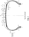
- FIG. 1 is a cross-sectional view in a tire meridian direction illustrating a pneumatic tire according to an embodiment of the invention.
- FIG. 1 is a cross-sectional view of a half region in the tire radial direction.
- FIG. 1 illustrates a radial tire for a passenger vehicle as an example of a pneumatic tire.
- cross section in a tire meridian direction refers to a cross section of the tire taken along a plane that includes the tire rotation axis (not illustrated).
- Reference sign CL denotes the tire equatorial plane and refers to a plane normal to the tire rotation axis that passes through the center point of the tire in the tire rotation axis direction.
- Tone lateral direction refers to the direction parallel with the tire rotation axis.
- Tonire radial direction refers to the direction vertical to the tire rotation axis.
- a pneumatic tire 1 has an annular structure with the tire rotation axis as its center and includes a pair of bead cores 11, 11, a pair of bead fillers 12, 12, a carcass layer 13, a belt layer 14, a tread rubber 15, a pair of sidewall rubbers 16, 16, and a pair of rim cushion rubbers 17, 17 (see FIG. 1 ).
- the pair of bead cores 11, 11 are annular members constituted by bead wires bundled together.
- the pair of bead cores 11, 11 constitute the cores of the left and right bead portions.
- the pair of bead fillers 12, 12 are disposed outward of the pair of bead cores 11, 11 in the tire radial direction and constitute the bead portions.
- the carcass layer 13 has a single layer structure made of one carcass ply or a multilayer structure made of carcass plies, and extends between the left and right bead cores 11, 11 in a toroidal shape, forming the framework of the tire. Additionally, both end portions of the carcass layer 13 are turned back outwardly in the tire lateral direction so as to wrap around the bead cores 11 and the bead fillers 12 and fixed.
- the carcass ply (plies) of the carcass layer 13 is made by performing a process of covering carcass cords made of steel or an organic fiber material (e.g. aramid, nylon, polyester, rayon, or the like) with coating rubber and then a rolling process.
- the carcass ply (plies) has a carcass angle (defined as the longitudinal inclination angle of the carcass cords with respect to the tire circumferential direction), as an absolute value, from 80 degrees to 95 degrees.
- the belt layer 14 is a multilayer structure including a pair of cross belts 141, 142 and a belt cover 143 and is disposed around the outer circumference of the carcass layer 13.
- the pair of cross belts 141, 142 are made by performing a process of covering belt cords made of steel or an organic fiber material with coating rubber and then a rolling process.
- the cross belts 141, 142 have a belt angle, as an absolute value, from 20 degrees to 55 degrees.
- the pair of cross belts 141, 142 have belt angles (defined as the longitudinal inclination angle of the belt cords with respect to the tire circumferential direction) of opposite signs, and the belts are layered so that the longitudinal directions of the belt cords intersect each other (i.e. crossply structure).
- the belt cover 143 is made by coating belt cords made of steel or an organic fiber material with coating rubber.
- the belt cover 143 has a belt angle, as an absolute value, from 0 degrees to 10 degrees.
- the belt cover 143 for example, is a strip material made by covering a belt cord or belt cords with coating rubber. The strip material is spirally wound around the outer circumferential surface of the cross belts 141, 142 a number of times in the tire circumferential direction.
- the tread rubber 15 is disposed outward of the carcass layer 13 and the belt layer 14 in the tire radial direction and constitutes a tread portion.
- the pair of sidewall rubbers 16, 16 are disposed outward of the carcass layer 13 in the tire lateral direction and constitute left and right sidewall portions.
- the pair of rim cushion rubbers 17, 17 are disposed inward of the left and right bead cores 11, 11 and the turned back portions of the carcass layer 13 in the tire radial direction.
- the pair of rim cushion rubbers 17, 17 constitute the contact surfaces of the left and right bead portions with the rim flanges.
- FIG. 2 is a plan view illustrating a tread surface of the pneumatic tire illustrated in FIG. 1 .
- FIG. 2 illustrates a tread pattern of a studless tire.
- tire circumferential direction refers to the direction revolving about the tire rotation axis.
- Reference sign T denotes a tire ground contact edge.
- the pneumatic tire 1 is provided with, in the tread surface, circumferential main grooves 21, 22 extending in the tire circumferential direction, land portions 31 to 33 defined by the circumferential main grooves 21, 22, and lug grooves 311, 322A, 322B disposed in the land portions 31 to 33.
- Main groove refers to a groove that is required to have a wear indicator as stipulated by JATMA and typically has a groove width of 5.0 mm or greater and a groove depth of 6.5 mm or greater.
- “Lug groove” refers to a lateral groove extending in the tire lateral direction that typically has a groove width of 1.0 mm or greater and a groove depth of 3.0 mm or greater.
- “Sipe” refers to a cut formed in a tread contact surface that typically has a sipe width of less than 1.0 mm and a sipe depth of 2.0 mm or greater and closes when the tire comes into contact with the ground.
- the groove width is the maximum distance between the left and right groove walls at the groove opening portion and is measured when the tire is mounted on a specified rim, inflated to the specified internal pressure, and in an unloaded state.
- the groove width is measured with reference to the intersection points where the tread contact surface and extension lines of the groove walls meet, when viewed in a cross-section normal to the groove length direction.
- the groove width is measured with reference to the center line of the amplitude of the groove walls.
- the groove depth is the maximum distance from the tread contact surface to the groove bottom and is measured when the tire is mounted on a specified rim, inflated to the specified internal pressure, and in an unloaded state. Additionally, in configurations in which the grooves include an uneven portion or sipes on the groove bottom, the groove depth is measured excluding these portions.
- the sipe width is the maximum distance of the opening width of the sipe at the road contact surface of the land portion and is measured when the tire is mounted on a specified rim, inflated to the specified internal pressure, and in an unloaded state.
- the sipe depth is the maximum distance from the tread contact surface to the sipe bottom and is measured when the tire is mounted on a specified rim, inflated to the specified internal pressure, and in an unloaded state. Additionally, in configurations in which the sipes include an uneven portion on the groove bottom, the sipe depth is measured excluding these portions.
- “Specified rim” refers to an "applicable rim” defined by the Japan Automobile Tyre Manufacturers Association Inc. (JATMA), a “Design Rim” defined by the Tire and Rim Association, Inc. (TRA), or a “Measuring Rim” defined by the European Tyre and Rim Technical Organisation (ETRTO). Additionally, “specified internal pressure” refers to a “maximum air pressure” defined by JATMA, to the maximum value in "TIRE LOAD LIMITS AT VARIOUS COLD INFLATION PRESSURES" defined by TRA, and to "INFLATION PRESSURES" defined by ETRTO.
- JATMA Japan Automobile Tyre Manufacturers Association Inc.
- TRA Tire and Rim Association, Inc.
- ETRTO European Tyre and Rim Technical Organisation
- specified load refers to a “maximum load capacity” defined by JATMA, the maximum value in "TIRE LOAD LIMITS AT VARIOUS COLD INFLATION PRESSURES" defined by TRA, or "LOAD CAPACITY” defined by ETRTO.
- JATMA for a passenger vehicle tire, the specified internal pressure is an air pressure of 180 kPa, and the specified load is 88% of the maximum load capacity.
- the pneumatic tire 1 has a tread pattern being substantially point symmetrical to a point on a tire equatorial plane CL.
- the pneumatic tire 1 may include a tread pattern with left-right symmetry or left-right asymmetry centered on the tire equatorial plane CL, or a tread pattern with directionality in the tire rotation direction (not illustrated).
- two circumferential main grooves 21, 22 are disposed in each left and right region on either side of the tire equatorial plane CL as a boundary.
- the circumferential main grooves 21, 22 are disposed having left-right symmetry centered on the tire equatorial plane CL.
- Five land portions 31 to 33 are defined by the circumferential main grooves 21, 22.
- One land portion 33 is disposed on the tire equatorial plane CL.
- circumferential main grooves may be provided, or the circumferential main grooves may be disposed with left-right asymmetry centered on the tire equatorial plane CL (not illustrated).
- the land portion may be disposed at a position away from the tire equatorial plane CL by disposing one circumferential main groove on the tire equatorial plane CL (not illustrated).
- the left and right circumferential main grooves 21, 21 located outermost in the tire lateral direction are defined as outermost circumferential main grooves.
- the distance (dimension symbol omitted in drawings) from the tire equatorial plane CL to the outermost circumferential main groove 21 ranges from 20% to 35% of a tire ground contact width TW.
- Tire ground contact width TW is the maximum linear distance in the tire axial direction of a contact surface between the tire and a flat plate measured when the tire is mounted on a specified rim, inflated to the specified internal pressure, placed vertically on the flat plate in a static state, and loaded with a load corresponding to the specified load.
- Tire ground contact edge T is defined as the maximum width position in the tire axial direction of the contact surface between the tire and a flat plate when the tire is mounted on a specified rim, inflated to the specified internal pressure, placed vertically on the flat plate in a static state, and loaded with a load corresponding to the specified load.
- the land portion 31 located outermost in the tire lateral direction among the land portions 31 to 33 defined by the circumferential main grooves 21, 22 is defined as a shoulder land portion.
- the shoulder land portion 31 is an outer land portion in the tire lateral direction defined by the outermost circumferential main groove 21 and includes the tire ground contact edge T on its road contact surface.
- the land portion 32 second from the outer side in the tire lateral direction is defined as a second land portion.
- the second land portion 32 is an inner land portion in the tire lateral direction defined by the outermost circumferential main groove 21 and is located adjacent to the shoulder land portion 31 interposing the outermost circumferential main groove 21.
- the land portion 33 disposed closer to the tire equatorial plane CL than the second land portion 32 is defined as a center land portion.
- the center land portion 33 may be disposed on the tire equatorial plane CL ( FIG. 2 ) or disposed away from the tire equatorial plane CL (not illustrated).
- center land portion 33 is provided in the configuration of FIG. 2 . However, in a configuration with five or more circumferential main grooves, a plurality of center land portions may be defined (not illustrated). Additionally, in a configuration with three circumferential main grooves, the center land portion may also be the second land portion (not illustrated).
- all of the circumferential main grooves 21, 22 have a straight shape.
- at least one or all of the circumferential main grooves 21, 22 may have a zigzag shape, a wave-like shape, or a step-like shape with amplitude in the tire lateral direction (not illustrated).
- the pneumatic tire 1 employs the following configuration to provide performance on snow and performance on ice in a compatible manner.
- FIG. 3 is a plan view illustrating one land portion of the tread pattern illustrated in FIG. 2 .
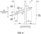
- FIG. 4 is an explanatory diagram illustrating a lug groove of the land portion illustrated in FIG. 3 .
- FIG. 3 is an enlarged plan view of the second land portion 32
- FIG. 4 is an extracted and simplified view of the shape of the lug groove 322 (322A, 322B) disposed in the second land portion 32.
- the second land portion 32 includes a single circumferential narrow groove 321, and two kinds of plurality of lug grooves 322A, 322B.
- the circumferential narrow groove 321 is a narrow groove extending in the tire circumferential direction and is disposed in a central portion of the land portion 32 in the width direction.
- a groove width Ws of the circumferential narrow groove 321 preferably has the relationship with a groove width Wm of the outermost circumferential main groove 21 satisfying 0.20 ⁇ Ws/Wm ⁇ 0.50.
- the circumferential narrow groove 321 and the outermost circumferential main groove 21 disposed in the same region are the subjects of comparison.
- a distance Ds from one edge portion on one side of the land portion 32 to the groove center line of the circumferential narrow groove 321 and a width W1 of the land portion 32 preferably have the relationship 0.35 ⁇ Ds/W1 ⁇ 0.65, and more preferably have the relationship 0.40 ⁇ Ds/W1 ⁇ 0.55. In this way, the rigidity of the left and right regions of the land portion 32 divided by the circumferential narrow groove 321 is made uniform.
- the distance Ds is measured as the distance in the tire axial direction from a measurement point of the groove width of the circumferential main grooves 21, 22 to the groove center line of the circumferential narrow groove 321, when the tire is mounted on a specified rim, inflated to the specified internal pressure, and in an unloaded state.
- the width W1 of the land portion 32 is measured using the measurement points of the groove width of the left and right circumferential main grooves 21, 22 as a reference.
- the width W1 of the second land portion 32 and the tire ground contact width TW have the range 0.10 ⁇ W1/TW ⁇ 0.30.
- the circumferential narrow groove 321 has a straight shape.
- the circumferential narrow groove 321 may have a zigzag shape, a wave-like shape, or a step-like shape with amplitude in the tire lateral direction.
- the edge components of the land portion 32 increase and performance on snow and performance on ice are improved.
- the groove depth of the circumferential narrow groove 321 is shallower than the groove depth of the circumferential main grooves 21, 22 on the left and right of the land portion 32. Thus, the rigidity of the land portion 32 is ensured.
- the two kinds of lug grooves 322A, 322B are lateral grooves extending in the tire lateral direction through the circumferential narrow groove 321. They are classified as first lug groove 322A and second lug groove 322B.
- the first lug groove 322A includes an end portion that opens to the edge portion on one side (left side in FIG. 3 ) of the land portion 32 and an end portion that terminates within the land portion 32.
- the second lug groove 322B includes an end portion that opens to the edge portion on the other side (right side in FIG. 3 ) of the land portion 32 and an end portion that terminates within the land portion 32.
- first lug groove 322A and the second lug groove 322B have a semi-closed structure that does not traverse the land portion 32. Also, the first lug groove 322A and the second lug groove 322B open into different circumferential main grooves 21, 22.
- the first lug groove 322A and the second lug groove 322B extend in the tire lateral direction through the circumferential narrow groove 321 and open into the circumferential main grooves 21, 22.
- groove volume is increased, and the shear force in snow and the snow discharge properties of the land portion 32 on snow-covered road surfaces is improved.
- the first lug groove 322A and the second lug groove 322B include an end portion that terminates within the land portion 32.
- the ground contact area of the land portion 32 is ensured, and adhesion and friction forces on icy road surfaces are ensured. In this way, the performance on snow and the performance on ice of the tire are achieved in a compatible manner.
- first lug groove 322A and the second lug groove 322B are alternately disposed separated from one another by a predetermined interval in the tire circumferential direction.
- first lug groove 322A and the second lug groove 322B alternate from left to right in opening to the left and right circumferential main grooves 21, 22 and alternate from left to right in meeting the circumferential narrow groove 321.
- many intersection portions of the first lug groove 322A and the second lug groove 322B with the circumferential main grooves 21, 22 and the circumferential narrow groove 321 are ensured. This allows the shear force in snow and the snow discharge properties of the land portion 32 on snow-covered road surfaces to be improved.
- the opening portions of the first lug groove 322A and the second lug groove 322B are alternately disposed from left to right with respect to the left and right edge portions of the land portion 32. This allows the shear force in snow and edge effect of the lug grooves 322A, 322B when the vehicle is turning to be improved compared to a configuration in which the plurality of lug grooves only open into the edge portion on one side (not illustrated).
- intersection points PA, PB Intersection points of the groove center lines of the first lug groove 322A and the second lug groove 322B with the groove center line of the circumferential narrow groove 321 are defined as intersection points PA, PB.
- a distance L1 in the tire circumferential direction between the intersection points PA, PA of an adjacent pair of the first lug grooves 322A, 322A and a distance L2 from the intersection point PA of the first lug groove 322A to the intersection point PB of the second lug groove 322B preferably have the relationship 0.35 ⁇ L2/L1 ⁇ 0.65 and more preferably have the relationship 0.40 ⁇ L2/L1 ⁇ 0.60. This allows the arrangement interval between the lug grooves 322A, 322B in the land portion 32 to be made uniform, and the rigidity of the region defined by adjacent lug grooves 322A, 322B in the tire circumferential direction to be made uniform.
- the second land portion 32 is defined by left and right circumferential main grooves 21, 22, the circumferential narrow groove 321, and two kinds of lug grooves 322A, 322B to form blocks 323A, 323B.
- the first lug groove 322A and the second lug groove 322B alternately open in the tire circumferential direction to the left and right circumferential main grooves 21, 22 and the circumferential narrow groove 321.
- the blocks 323A, 323B are arranged in a staggered manner around the entire circumference of the tire. This allows block rigidity to be made uniform and the amount of groove edge to be maximized, greatly improving performance on ice.
- first lug groove 322A and the second lug groove 322B have a structure with line symmetry with one another and are inclined with the same inclination angle in opposite direction with respect to the tire circumferential direction.
- the blocks 323A, 323B located on the left and right of the circumferential narrow groove 321 have a same road contact surface with a parallelogram shape. In this way, the ground contact shapes of the blocks 323A, 323B are made uniform.
- the first lug groove 322A and the second lug groove 322B have a groove depth which is shallower than the groove depth of the circumferential main grooves 21, 22. Thus, the rigidity of the land portion 32 is ensured.
- Adjacent blocks 323A, 323A; 323A, 323B; 323B, 323B have a ground contact area ratio preferably ranging from 0.80 to 1.20 and more preferably ranging from 0.90 to 1.10. In this way, the ground contact area of adjacent blocks is made uniform.
- the ground contact area of the block is measured at a contact surface between a tire and a flat plate when the tire is mounted on a specified rim, inflated to the specified internal pressure, placed vertically on the flat plate in a static state, and loaded with a load corresponding to the specified load.
- an inclination angle ⁇ of the lug groove 322A (322B) with respect to the tire circumferential direction is preferably in the range 40 degrees ⁇ ⁇ ⁇ 85 degrees and more preferably in the range 60 degrees ⁇ ⁇ ⁇ 75 degrees. In this way, the inclination angle ⁇ of the lug groove 322A (322B) is made appropriate.
- the inclination angle ⁇ of the lug groove is measured as the angle between the groove center line of the lug groove and the tire circumferential direction.
- a groove width Wg1 of the lug groove 322A (322B) at the meeting position with the circumferential narrow groove 321 and a groove width Wg2 of the lug groove 322A (322B) at the edge portion of the land portion 32 have the relationship Wg2 ⁇ Wg1.
- the Wg1/Wg2 ratio is preferably in the range 0.20 ⁇ Wg2/Wg1 ⁇ 0.70.
- the maximum groove width (groove width Wg1 in FIG. 4 ) of the lug grooves 322A, 322B of the second land portion 32 preferably ranges from 25% to 60% of the groove width Wm (see FIG. 2 ) of the outermost circumferential main groove 21 and more preferably ranges from 30% to 50%. Accordingly, the lug grooves 322A, 322B of the second land portion 32 have a narrower groove width than a general lug groove. In this way, the number of lug grooves 322A, 322B and edge components are ensured. Also, the narrowed groove width of the lug grooves 322A, 322B ensures a sufficient ground contact area.
- the lug groove 322A (322B) has a step-like shape with a narrowed groove width at the opening portion to the circumferential main groove 21, 22.
- the lug groove 322A (322B) includes a broad width portion 3221 and a narrow width portion 3222 that connect in a straight line.
- the broad width portion 3221 extends through the circumferential narrow groove 321 and terminates within the land portion 32.
- the narrow width portion 3222 opens into the circumferential main groove 21, 22.
- the edge portion on one side (lower side in FIG. 4 ) of the lug groove 322A (322B) has a linear shape.
- the edge portion on the other side (upper side in FIG.
- the broad width portion 3221 and the narrow width portion 3222 have constant groove widths.
- the broad width portion 3221 is shaped overall like a parallelogram.
- the groove width Wg2 of the narrow width portion 3222 has the range 1 mm ⁇ Wg2.
- the narrow width portion 3222 is set to not close when the tire comes into contact with the ground. This allows the edge components of the lug groove 322A (322B) when the tire comes into contact with the ground to be appropriately ensured.
- the narrow width portion 3222 may have a groove width similar to that of the sipes and may close when the tire comes into contact with the ground. This allows the rigidity of the edge portions of the second land portion 32 when the tire comes into contact with the ground to be increased.
- an extension distance D2 in the tire lateral direction of the narrow width portion 3222 of the lug groove 322A (322B) and a width Wb2 of the block 323A (323B) including the narrow width portion 3222 preferably have the relationship 0.20 ⁇ D2/Wb2 ⁇ 0.50 and more preferably have the relationship 0.30 ⁇ D2/Wb2 ⁇ 0.40. This allows the extension distance D2 of the narrow width portion 3222 to be appropriately set.
- a distance D1 from the edge portion of the block 323B (323A) defined by the circumferential narrow groove 321 to the terminating end portion of the lug groove 322A (322B) and a width Wb1 of the block 323B (323A) preferably have the relationship 0.30 ⁇ D1/Wb1 ⁇ 0.70 and more preferably have the relationship 0.40 ⁇ D1/Wb1 ⁇ 0.60. In this way, the position of the terminating end portion of the lug groove 322A (322B) is made appropriate.
- the lug grooves 322A, 322B have a straight shape overall. However, no such limitation is intended, and the lug grooves 322A, 322B may have an arc shape, an S-shape, a bent shape, or the like (not illustrated).
- a total number N1 of the lug grooves 322A, 322B disposed in the second land portion 32 and a total number Nsh of the lug grooves 311 disposed in the shoulder land portions 31 preferably have the relationship 1.2 ⁇ N1/Nsh ⁇ 3.5 and more preferably have the relationship 1.5 ⁇ N1/Nsh ⁇ 2.5.
- the edge components formed on the second land portion 32 contribute greatly to performance on ice. In this way, as described above, by densely arranging the lug grooves 322A, 322B in the second land portion 32, the edge components of the second land portion 32 can be increased and an effect of improving performance on ice can be efficiently obtained. Also, by sparsely arranging the lug grooves 311 in the shoulder land portions 31, the rigidity of the shoulder land portion 31 can be ensured.
- the shoulder land portion 31 and the second land portion 32 have the same pitch number.
- one lug groove 311 is disposed for each pitch.
- a set of lug grooves 322A, 322B is disposed for each pitch.
- the groove width (the maximum groove width Wg1 in FIG. 4 ) of the lug grooves 322A, 322B disposed in the second land portion 32 is less than the groove width (dimension symbol omitted in drawings) of the lug groove 311 disposed in the shoulder land portion 31.
- the groove width of the lug grooves 322A, 322B of the second land portion 32 preferably ranges from 15% to 60% of the groove width of the lug groove 311 of the shoulder land portion 31 and more preferably ranges from 20% to 50%.
- the total number N1 of the lug grooves 322A, 322B is large and the edge components of the second land portion 32 are increased, but the groove width of the lug grooves 322A, 322B is narrow to ensure sufficient ground contact area for the second land portion 32.
- the groove area ratio of the shoulder land portion 31 and the groove area ratio of the second land portion 32 are made uniform.
- the shoulder land portion 31 and the second land portion 32 have the same pitch number.
- the land portions 31, 32 may have different pitch numbers.
- the pitch number of the second land portion 32 is preferably greater than the pitch number of the shoulder land portion 31. This allows an effect of improving performance on ice to be efficiently obtained and the rigidity of the shoulder land portions 31 to be appropriately ensured.
- the land portions 31 to 33 includes a plurality of sipes (dimension symbol omitted in drawings).
- the second land portion 32 includes a plurality of sipes 4 in the road contact surface of the blocks 323A, 323B on the left and right of the circumferential narrow groove 321 as a boundary.
- the inclination direction of the sipes 4 disposed in the blocks 323A on one side of the circumferential narrow groove 321 as a boundary is different from the inclination direction of the sipes 4 disposed in the blocks 323B on the other side.
- the sipes 4 are disposed parallel with the first lug grooves 322A and are inclined upward to the right in the drawings, mimicking the first lug grooves 322A.
- the sipes 4 are disposed parallel with the second lug grooves 322B and are inclined downward to the right, mimicking the second lug groove 322B. In this way, the edge effect of the sipes 4 when the vehicle is turning can be increased.
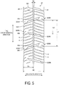
- FIG. 5 is an explanatory diagram of a modified example of the pneumatic tire illustrated in FIG. 1 .
- FIG. 5 is an enlarged plan view of the second land portion 32.
- the left and right circumferential main grooves 21, 22 defining the second land portion 32 have a straight shape, and the left and right edge portions of the second land portion 32 have a straight shape.
- At least one or both of the circumferential main grooves 21, 22 defining the second land portion 32 may have a zigzag shape, a wave-like shape, or a step-like shape with amplitude in the tire lateral direction. Additionally, at least one or both of the edge portions of the second land portion 32 may have a zigzag shape, a wave-like shape, or a step-like shape with amplitude in the tire lateral direction. Furthermore, the shape of the circumferential main grooves 21, 22 may not match the shape of the edge portions of the second land portion 32.
- the left and right circumferential main grooves 21, 22 defining the second land portion 32 have a straight shape around the entire circumference of the tire.
- the edge portion of the second land portion 32 on the side closer to the tire equatorial plane CL has a zigzag shape with amplitude in the tire equatorial plane around the entire circumference of the tire.
- one block 323A defined by the circumferential narrow groove 321 and a pair of the lug grooves 322A, 322A include a pair of chamfered portions 324, 325 on the edge portion on the side closer to the circumferential main groove 22.
- the first chamfered portion 324 has an elongated structure and extends roughly from an opening portion of one of the lug grooves 322A near to an adjacent opening portion of the other lug grooves 322A in the tire circumferential direction.
- the width of the first chamfered portion 324 is greatest at the opening portion of one of the lug grooves 322A and decreases towards the opening portion of the other lug groove 322A.
- the second chamfered portion 325 has a short structure and is formed at the opening portion of the other lug groove 322A.
- the blocks 323A of the second land portion 32 include the pair of chamfered portions 324, 325 at the edge portion on the side closer to the circumferential main groove 22. This gives the edge portion of the second land portion 32 on the side closer to the tire equatorial plane of the road contact surface a zigzag shape overall.
- the pneumatic tire 1 includes two circumferential main grooves 21, 22 disposed in the region on one side of the tire equatorial plane CL as a boundary and a land portion 32 defined by the circumferential main grooves 21, 22 (see FIG. 2 ).
- the land portion 32 includes the circumferential narrow groove 321 extending in the tire circumferential direction and sets of the first lug groove 322A and the second lug groove 322B extending the tire lateral direction through the circumferential narrow groove 321 (see FIG. 3 ).
- the first lug groove 322A includes an end portion that opens to the edge portion on one side of the land portion 32 and another end portion that terminates within the land portion 32.
- the second lug groove 322B includes an end portion that opens to the edge portion on the other side of the land portion 32 and another end portion that terminates within the land portion 32. Additionally, the first lug groove 322A and the second lug groove 322B are alternately disposed in the tire circumferential direction.
- the first lug groove 322A and the second lug groove 322B extend in the tire lateral direction through the circumferential narrow groove 321 and open into the circumferential main grooves 21, 22.
- the number of groove intersection portions is increased, groove volume is increased, and the shear force in snow and snow discharge properties of the land portion 32 on snow-covered road surfaces is improved.
- the first lug groove 322A and the second lug groove 322B include an end that terminates within the land portion 32.
- the ground contact area of the land portion 32 is ensured, and adhesion and friction forces on icy road surfaces are ensured. This is advantageous in that the performance on snow and the performance on ice of the tire are achieved in a compatible manner.
- first lug groove 322A and the second lug groove 322B are alternately disposed in the tire circumferential direction.
- the first lug groove 322A and the second lug groove 322B alternately open into the left and right edge portions of the land portion 32.
- This allows the edge effect of the lug grooves 322A, 322B when the vehicle is turning to be improved compared to a configuration in which the lug grooves only open into the edge portion on one side (not illustrated). This is advantageous in that the turning performance of the tire on icy road surfaces in particular is improved.
- the land portion 32 includes blocks 323A, 323B defined by two circumferential main grooves 21, 22, the circumferential narrow groove 321, and the plurality of sets of the first lug groove 322A and the second lug groove 322B (see FIG. 3 ).
- the blocks 323A, 323B are arranged in a staggered manner around the entire circumference of the tire.
- block rigidity can be made uniform and the amount of groove edge can be maximized. This is advantageous in that the performance on ice of the tire is greatly improved.
- adjacent blocks 323A, 323A; 323A, 323B; 323B, 323B have a ground contact area ratio ranging from 0.80 to 1.20 (see FIG. 3 ). This is advantageous in that the ground contact area of adjacent blocks is made uniform and uneven wear of the blocks is suppressed.
- the first lug groove 322A and the second lug groove 322B are inclined in opposite directions with respect to the tire circumferential direction (see FIG. 3 ).
- the edge effect of the lug grooves 322A, 322B when the vehicle is turning is improved compared to a configuration in which all of the lug grooves in the land portion are inclined in the same direction (not illustrated). This is advantageous in that the turning performance of the tire on icy road surfaces in particular is improved.
- the inclination angle ⁇ of the first lug groove 322A and the second lug groove 322B with respect to the tire circumferential direction is in the range 40 degrees ⁇ ⁇ ⁇ 85 degrees (see FIG. 4 ).
- the inclination angle ⁇ is appropriately ensured and the traction characteristics attributable to the lug grooves 322A, 322B are ensured.
- ⁇ ⁇ 85 degrees an effect of improving turning performance on ice attributable to the inclination of the lug grooves 322A, 322B can be appropriately obtained.
- the groove width Wg1 of the first lug groove 322A and the second lug groove 322B at the meeting positions with the circumferential narrow groove 321 and the groove width Wg2 of the first lug groove 322A and the second lug groove 322B at the edge portions of the land portion 32 have the relationship Wg2 ⁇ Wg1 (see FIG. 4 ).
- the first lug groove 322A and the second lug groove 322B have a step-like shape, with the groove width narrowed at the opening portions to the circumferential main grooves 21, 22 (see FIG. 4 ). This is advantageous in that the rigidity of the edge portions of the second land portion 32 is effectively ensured.
- the land portion 32 includes blocks 323A, 323B defined by two circumferential main grooves 21, 22, the circumferential narrow groove 321, and the plurality of sets of the first lug groove 322A and the second lug groove 322B (see FIG. 3 ).
- the extension distance D2 in the tire lateral direction of the narrow width portion 3222 of the step-like shape of the first lug groove 322A and the second lug groove 322B and the width Wb2 of the blocks 323A, 323B including the narrow width portion 3222 have the relationship 0.20 ⁇ D2/Wb2 ⁇ 0.50 (see FIG. 4 ). This is advantageous in that the extension distance D2 of the narrow width portion 3222 is appropriately set.
- the distance L1 in the tire circumferential direction between the intersection points PA, PA of an adjacent pair of the first lug grooves 322A, 322A, and the distance L2 from the intersection point PA of the first lug groove 322A to the intersection point PB of the second lug groove 322B have the relationship 0.35 ⁇ L2/L1 ⁇ 0.65 (see FIG. 3 ), where the intersection points of the first lug groove 322A and the second lug groove 322B with the circumferential narrow groove 321 are defined as the intersection points PA, PB.
- the land portion 32 includes blocks 323A, 323B defined by two circumferential main grooves 21, 22, the circumferential narrow groove 321, and the plurality of sets of the first lug groove 322A and the second lug groove 322B (see FIG. 3 ).
- the distance D1 from the edge portion of the blocks 323A, 323B to the terminating end portion of the lug groove 322A or the lug groove 322B and the width Wb1 of the blocks 323A, 323B have the relationship 0.30 ⁇ D1/Wb1 ⁇ 0.70 (see FIG. 4 ). This is advantageous in that the position of the terminating end portion of the lug grooves 322A, 322B is made appropriate.
- the circumferential narrow groove 321, the first lug groove 322A, and the second lug groove 322B have a groove depth which is shallower than the groove depth (not illustrated) of the circumferential main grooves 21, 22 (see FIG. 3 ). This is advantageous in that the rigidity of the land portion 32 is ensured and the performance on ice and the dry performance of the tire is ensured.
- the total number N1 of the first lug groove 322A and the second lug groove 322B disposed in the second land portion 32 and the total number Nsh of the lug grooves 311 disposed in the shoulder land portions 31 have the relationship 1.2 ⁇ N1/Nsh ⁇ 3.5 (see FIG. 2 ).
- This configuration is advantageous in that by densely arranging the lug grooves 322A, 322B in the second land portion 32, the edge components of the second land portion 32 can be increased and an effect of improving performance on ice can be efficiently obtained.
- This is also advantageous in that by sparsely arranging the lug grooves 311 in the shoulder land portions 31, the rigidity of the shoulder land portion 31 can be ensured.
- the groove width (the maximum groove width Wg1 in FIG. 4 ) of the lug grooves 322A, 322B disposed in the land portion 32 is less than the groove width of the lug groove 311 disposed in the shoulder land portion 31 (see FIG. 2 ).
- the land portion 32 includes a plurality of sipes 4 and the inclination direction of the sipes 4 disposed in the region on one side of the circumferential narrow groove 321 as a boundary is different from the inclination direction of the sipes 4 disposed in the region on the other side each other (see FIG. 3 ).
- This is advantageous in that the edge effect of the sipes 4 when the vehicle is turning is improved, and in particular, the turning performance of the tire on icy road surfaces is improved.
- the land portion 32 is preferably disposed in the inner region in the vehicle width direction of the tire equatorial plane CL as a boundary when the tire is mounted on the vehicle (see FIG. 2 ).
- the second land portion 32 in the inner region in the vehicle width direction contributes greatly to the performance on snow and the performance on ice of the tire.
- giving the second land portion 32 in the inner region in the vehicle width direction the configuration described above is advantageous in that the performance on snow and the performance on ice of the tire can be efficiently achieved in a compatible manner.
- a mounting direction indicator portion that specifies the mounting direction on the vehicle for example, includes a mark or grooves/ridges on the sidewall portion of the tire.
- ECE R30 Economic Commission for Europe Regulation 30 requires that a mounting direction indicator portion is provided on the sidewall portion on the outer side in the vehicle width direction when the tire is mounted on a vehicle.
- FIG. 6 is a table showing the results of performance tests of pneumatic tires according to embodiments of the invention.
- test tires having a tire size of 195/65R15 91Q were mounted on specified rims having a rim size of 15x6J, adjusted to an air pressure of 210 kPa, and loaded with the specified load specified by JATMA. Also, the test tires were mounted on all wheels of a test vehicle, a front-engine front-drive (FF) sedan with an engine displacement of 1600 cc.
- FF front-engine front-drive
- the test tires of Examples 1 to 10 have the configuration illustrated in FIGS. 1 to 3 .
- the tread width TW is 156 mm.
- the groove width Wm of the outermost circumferential main groove 21 is 6.0 mm.
- the width W1 (see FIG. 3 ) of the second land portion 32 is 30 mm.
- the groove width Ws of the circumferential narrow groove 321 of the second land portion 32 is 2.0 mm.
- the ratio Ds/W1 is 0.50.
- the lug grooves 322A, 322B of the second land portion 32 have a straight shape with a constant groove width Wg1 and are not provided with the narrow width portion 3222.
- the lug grooves 322A, 322B of the second land portion 32 have the step-like shape illustrated in FIG. 4 , and the groove width Wg1 of the broad width portion 3221 is 2.3 mm.
- the ratio L2/L1 of the arrangement interval of the lug grooves 322A, 322B of the second land portion 32 is 0.50.
- the sipe width of the sipes 4 is 0.4 mm.
- the test tire of the Conventional Example has the configuration of Example 1 except that the second lug groove 322B of the second land portion 32 as illustrated in FIG. 3 has an open structure that extends through the second land portion 32. Also, all of the lug grooves 322A, 322B are inclined in the same direction with respect to the tire circumferential direction.
- test tires of Examples 1 to 10 achieve performance on snow and performance on ice in a compatible manner.
Claims (16)
- Luftreifen (1), umfassend:zwei Hauptumfangsrillen (21, 22), die in einem Bereich auf einer Seite einer Reifenäquatorialebene (CL) als Grenze angeordnet sind; undeinen Stegabschnitt (32), der durch die zwei Hauptumfangsrillen (21, 22) definiert wird,wobei der Stegabschnitt (32) eine schmale Umfangsrille (321), die sich in einer Reifenumfangsrichtung erstreckt, und eine Mehrzahl von Sätzen aus einer ersten Stollenrille (322A) und einer zweiten Stollenrille (322B), die sich in einer Reifenquerrichtung durch die schmale Umfangsrille (321) erstrecken, einschließt;wobei die erste Stollenrille (322A) einen Endabschnitt, der sich zu einem Randabschnitt auf einer Seite des Stegabschnitts (32) öffnet, und einen anderen Endabschnitt, der innerhalb des Stegabschnitts (32) endet, aufweist;wobei die zweite Stollenrille (322B) einen Endabschnitt, der sich zu einem anderen Randabschnitt des Stegabschnitts (32) öffnet, und einen anderen Endabschnitt, der innerhalb des Stegabschnitts (32) endet, einschließt; undwobei die erste Stollenrille (322A) und die zweite Stollenrille (322B) in Reifenumfangsrichtung abwechselnd angeordnet sind,dadurch gekennzeichnet, dassdie erste Stollenrille (322A) und die zweite Stollenrille (322B) in einander entgegengesetzten Richtungen in Bezug auf die Reifenumfangsrichtung geneigt sind.
- Luftreifen gemäß Anspruch 1, wobeider Stegabschnitt (32) eine Mehrzahl von Blöcken (323A, 323B) einschließt, die durch die zwei Hauptumfangsrillen (21, 22), die schmale Umfangsrille (321) und die Mehrzahl von Sätzen aus der ersten Stollenrille (322A) und der zweiten Stollenrille (322B) definiert sind; unddie Blöcke (323A, 323B) um einen gesamten Umfang des Luftreifens (1) herum versetzt angeordnet sind.
- Luftreifen nach Anspruch 2, wobei
ein Bodenkontaktflächenverhältnis von jeweils zwei einander benachbarten Blöcken (323A, 323B) im Bereich von 0,80 bis 1,20 liegt. - Luftreifen gemäß einem der Ansprüche 1 bis 3, wobei
ein Neigungswinkel θ der ersten Stollenrille (322A) und der zweiten Stollenrille (322B) in Bezug auf die Reifenumfangsrichtung in einem Bereich von 40 Grad ≤ θ ≤ 85 Grad liegt. - Luftreifen gemäß einem der Ansprüche 1 bis 4, wobei
eine Rillenbreite Wg1 der ersten Stollenrille (322A) und der zweiten Stollenrille (322B) an Stellen, an denen sie mit der schmalen Umfangsrille (321) zusammentreffen, und eine Rillenbreite Wg2 der ersten Stollenrille (322A) und der zweiten Stollenrille (322B) an den Randabschnitten des Stegabschnitts (32) eine Beziehung Wg2 < Wg1 aufweisen. - Luftreifen gemäß einem der Ansprüche 1 bis 5, wobei
die erste Stollenrille (322A) und die zweite Stollenrille (322B) eine stufenartige Form mit einer Rillenbreite aufweisen, die sich an Öffnungsabschnitten zu den zwei Hauptumfangsrillen (21, 22) verengt. - Luftreifen gemäß Anspruch 6, wobeider Stegabschnitt (32) eine Mehrzahl von Blöcken (323A, 323B) einschließt, die durch die zwei Hauptumfangsrillen (21, 22), die schmale Umfangsrille (321) und die Mehrzahl von Sätzen aus der ersten Stollenrille (322A) und der zweiten Stollenrille (322B) definiert sind; undein Abstand D2, über den sich ein schmaler Abschnitt (3222) der stufenartigen Form der ersten Stollenrille (322A) und der zweiten Stollenrille (322B) in Reifenquerrichtung erstreckt, und eine Breite Wb2 der Blöcke (323A, 323B), die den schmalen Abschnitt (3222) einschließen, eine Beziehung 0,20 ≤ D2/Wb2 ≤ 0,50 aufweisen.
- Luftreifen gemäß einem der Ansprüche 1 bis 7, wobei Schnittpunkte der ersten Stollenrille (322A) und der zweiten Stollenrille (322B) mit der schmalen Umfangsrille (321) als Schnittpunkte PA, PB definiert sind; und
ein Abstand L1 in Reifenumfangsrichtung zwischen den Schnittpunkten PA, PA von jeweils zwei einander benachbarten ersten Stollenrillen (322A) und ein Abstand L2 vom Schnittpunkt PA der ersten Stollenrille (322A) zum Schnittpunkt PB der zweiten Stollenrille (322B) die Beziehung 0,35 ≤ L2/L1 ≤ 0,65 aufweisen. - Luftreifen gemäß einem der Ansprüche 1 bis 8, wobei der Stegabschnitt (32) eine Mehrzahl von Blöcken (323A, 323B) einschließt, die durch die zwei Hauptumfangsrillen (21, 22), die schmale Umfangsrille (321) und die Mehrzahl von Sätzen aus der ersten Stollenrille (322A) und der zweiten Stollenrille (322B) definiert sind; und
ein Abstand D1 vom Randabschnitt des Blocks (323A, 323B) zu einem abschließenden Endabschnitt der ersten Stollenrille (322A) oder der zweiten Stollenrille (322B) und eine Breite Wb1 des Blocks (323A, 323B) eine Beziehung 0,30 ≤ D1/Wb1 ≤ 0,70 aufweisen. - Luftreifen gemäß einem der Ansprüche 1 bis 9, wobei die schmale Umfangsrille (321), die erste Stollenrille (322A) und die zweite Stollenrille (322B) eine Rillentiefe aufweisen, die geringer ist als eine Rillentiefe der zwei Hauptumfangsrillen (21, 22).
- Luftreifen gemäß einem der Ansprüche 1 bis 10, wobei eine Gesamtzahl N1 der ersten Stollenrille (322A) und der zweiten Stollenrille (322B), die in dem Stegabschnitt (32) angeordnet sind, und eine Gesamtzahl Nsh von Stollenrillen (311), die in einem Schulterstegabschnitt (31) angeordnet sind, eine Beziehung 1,2 ≤ N1/Nsh ≤ 3,5 aufweisen.
- Luftreifen gemäß einem der Ansprüche 1 bis 11, wobei eine Rillenbreite der Stollenrillen (322A, 322B), die in dem Stegabschnitt (32) angeordnet sind, kleiner ist als eine Rillenbreite der Stollenrillen (311), die in einem Schulterstegabschnitt (31) angeordnet sind.
- Luftreifen gemäß einem der Ansprüche 1 bis 12, wobei der Stegabschnitt (32) Lamellen (4) einschließt; und
eine Neigungsrichtung der Lamellen (4), die in einem Bereich auf einer Seite der schmalen Umfangsrille (321) als Grenze angeordnet sind, sich von einer Neigungsrichtung der Lamellen (4) unterscheidet, die in einem Bereich auf einer anderen Seite angeordnet sind. - Luftreifen gemäß einem der Ansprüche 1 bis 13, wobei der Stegabschnitt (32) in einem in Fahrzeugbreitenrichtung einwärts von der Reifenäquatorialebene (CL) liegenden Bereich als Grenze angeordnet ist, wenn der Luftreifen (1) an einem Fahrzeug montiert ist.
- Luftreifen (1), umfassend:zwei Hauptumfangsrillen (21, 22), die in einem Bereich auf einer Seite einer Reifenäquatorialebene (CL) als Grenze angeordnet sind; undeinen Stegabschnitt (32), der durch die zwei Hauptumfangsrillen (21, 22) definiert wird,wobei der Stegabschnitt (32) eine schmale Umfangsrille (321), die sich in einer Reifenumfangsrichtung erstreckt, und eine Mehrzahl von Sätzen aus einer ersten Stollenrille (322A) und einer zweiten Stollenrille (322B), die sich in einer Reifenquerrichtung durch die schmale Umfangsrille (321) erstrecken, einschließt;wobei die erste Stollenrille (322A) einen Endabschnitt, der sich zu einem Randabschnitt auf einer Seite des Stegabschnitts (32) öffnet, und einen anderen Endabschnitt, der innerhalb des Stegabschnitts (32) endet, aufweist;wobei die zweite Stollenrille (322B) einen Endabschnitt, der sich zu einem anderen Randabschnitt des Stegabschnitts (32) öffnet, und einen anderen Endabschnitt, der innerhalb des Stegabschnitts (32) endet, einschließt; und wobei die erste Stollenrille (322A) und die zweite Stollenrille (322B) in Reifenumfangsrichtung abwechselnd angeordnet sind,dadurch gekennzeichnet, dasseine Rillenbreite Wg1 der ersten Stollenrille (322A) und der zweiten Stollenrille (322B) an Stellen, an denen sie mit der schmalen Umfangsrille (321) zusammentreffen, und eine Rillenbreite Wg2 der ersten Stollenrille (322A) und der zweiten Stollenrille (322B) an den Randabschnitten des Stegabschnitts (32) eine Beziehung Wg2 < Wg1 aufweisen.
- Luftreifen (1), umfassend:zwei Hauptumfangsrillen (21, 22), die in einem Bereich auf einer Seite einer Reifenäquatorialebene (CL) als Grenze angeordnet sind; undeinen Stegabschnitt (32), der durch die zwei Hauptumfangsrillen (21, 22) definiert wird,wobei der Stegabschnitt (32) eine schmale Umfangsrille (321), die sich in einer Reifenumfangsrichtung erstreckt, und eine Mehrzahl von Sätzen einer ersten Stollenrille (322A) und einer zweiten Stollenrille (322B), die sich in einer Reifenquerrichtung durch die schmale Umfangsrille (321) erstrecken, einschließt;wobei die erste Stollenrille (322A) einen Endabschnitt, der sich zu einem Randabschnitt auf einer Seite des Stegabschnitts (32) öffnet, und einen anderen Endabschnitt, der innerhalb des Stegabschnitts (32) endet, aufweist;wobei die zweite Stollenrille (322B) einen Endabschnitt, der sich zu einem anderen Randabschnitt des Stegabschnitts (32) öffnet, und einen anderen Endabschnitt, der innerhalb des Stegabschnitts (32) endet, einschließt; und wobei die erste Stollenrille (322A) und die zweite Stollenrille (322B) in Reifenumfangsrichtung abwechselnd angeordnet sind,dadurch gekennzeichnet, dassder Stegabschnitt (32) eine Mehrzahl von Blöcken (323A, 323B) einschließt, die durch die zwei Hauptumfangsrillen (21, 22), die schmale Umfangsrille (321) und die Mehrzahl von Sätzen der ersten Stollenrille (322A) und der zweiten Stollenrille (322B) definiert sind; undein Abstand D1 vom Randabschnitt des Blocks (323A, 323B) zu einem abschließenden Endabschnitt der ersten Stollenrille (322A) oder der zweiten Stollenrille (322B) und eine Breite Wb1 des Blocks (323A, 323B) eine Beziehung 0,30 ≤ D1/Wb1 ≤ 0,70 aufweisen.
Applications Claiming Priority (2)
| Application Number | Priority Date | Filing Date | Title |
|---|---|---|---|
| JP2016137680A JP6825252B2 (ja) | 2016-07-12 | 2016-07-12 | 空気入りタイヤ |
| PCT/JP2017/025040 WO2018012438A1 (ja) | 2016-07-12 | 2017-07-07 | 空気入りタイヤ |
Publications (3)
| Publication Number | Publication Date |
|---|---|
| EP3486096A1 EP3486096A1 (de) | 2019-05-22 |
| EP3486096A4 EP3486096A4 (de) | 2020-02-19 |
| EP3486096B1 true EP3486096B1 (de) | 2021-09-15 |
Family
ID=60952425
Family Applications (1)
| Application Number | Title | Priority Date | Filing Date |
|---|---|---|---|
| EP17827566.5A Active EP3486096B1 (de) | 2016-07-12 | 2017-07-07 | Luftreifen |
Country Status (6)
| Country | Link |
|---|---|
| US (1) | US11524526B2 (de) |
| EP (1) | EP3486096B1 (de) |
| JP (1) | JP6825252B2 (de) |
| CN (1) | CN109414963B (de) |
| RU (1) | RU2714798C1 (de) |
| WO (1) | WO2018012438A1 (de) |
Family Cites Families (22)
| Publication number | Priority date | Publication date | Assignee | Title |
|---|---|---|---|---|
| JPS59176104A (ja) * | 1983-03-25 | 1984-10-05 | Yokohama Rubber Co Ltd:The | 重荷重用空気入りラジアルタイヤ |
| JP3391690B2 (ja) * | 1998-03-30 | 2003-03-31 | 住友ゴム工業株式会社 | 空気入りタイヤ |
| JP3332357B2 (ja) * | 1999-07-26 | 2002-10-07 | 住友ゴム工業株式会社 | 空気入りタイヤ |
| JP3682269B2 (ja) * | 2002-05-09 | 2005-08-10 | 住友ゴム工業株式会社 | 空気入りタイヤ |
| JP4205911B2 (ja) * | 2002-07-30 | 2009-01-07 | 株式会社ブリヂストン | 空気入りタイヤ |
| JP2005047397A (ja) * | 2003-07-29 | 2005-02-24 | Sumitomo Rubber Ind Ltd | 空気入りタイヤ |
| JP4011586B2 (ja) | 2005-02-25 | 2007-11-21 | 横浜ゴム株式会社 | 空気入りタイヤおよびタイヤ成形金型 |
| JP4918261B2 (ja) * | 2006-01-13 | 2012-04-18 | 株式会社ブリヂストン | 空気入りタイヤ |
| JP5160242B2 (ja) * | 2008-01-07 | 2013-03-13 | 東洋ゴム工業株式会社 | 空気入りタイヤ |
| JP5160243B2 (ja) * | 2008-01-09 | 2013-03-13 | 東洋ゴム工業株式会社 | 空気入りタイヤ |
| JP4312823B1 (ja) * | 2008-07-07 | 2009-08-12 | 横浜ゴム株式会社 | 空気入りタイヤおよびタイヤ成形金型ならびに空気入りタイヤの製造方法 |
| JP5686955B2 (ja) | 2009-04-24 | 2015-03-18 | 株式会社ブリヂストン | 空気入りタイヤ |
| JP4577455B1 (ja) * | 2010-03-18 | 2010-11-10 | 横浜ゴム株式会社 | 空気入りタイヤ |
| JP5790166B2 (ja) | 2011-06-02 | 2015-10-07 | 横浜ゴム株式会社 | 空気入りタイヤ |
| JP5852031B2 (ja) * | 2013-03-01 | 2016-02-03 | 株式会社ブリヂストン | 空気入りタイヤ |
| JP5945258B2 (ja) * | 2013-09-11 | 2016-07-05 | 住友ゴム工業株式会社 | 空気入りタイヤ |
| JP5926714B2 (ja) | 2013-10-07 | 2016-05-25 | 住友ゴム工業株式会社 | 空気入りタイヤ |
| JP6032242B2 (ja) * | 2014-05-12 | 2016-11-24 | 横浜ゴム株式会社 | 更生タイヤ |
| JP5922745B2 (ja) * | 2014-11-05 | 2016-05-24 | 株式会社ブリヂストン | 空気入りタイヤ |
| JP6084195B2 (ja) * | 2014-11-27 | 2017-02-22 | 住友ゴム工業株式会社 | 空気入りタイヤ |
| JP5910709B1 (ja) * | 2014-12-01 | 2016-04-27 | 横浜ゴム株式会社 | 空気入りタイヤ |
| FR3035821A1 (fr) * | 2015-05-07 | 2016-11-11 | Michelin & Cie | Bande de roulement comportant un bloc presentant une pluralite de decoupures |
-
2016
- 2016-07-12 JP JP2016137680A patent/JP6825252B2/ja active Active
-
2017
- 2017-07-07 RU RU2019103577A patent/RU2714798C1/ru active
- 2017-07-07 US US16/307,910 patent/US11524526B2/en active Active
- 2017-07-07 WO PCT/JP2017/025040 patent/WO2018012438A1/ja unknown
- 2017-07-07 CN CN201780042788.4A patent/CN109414963B/zh active Active
- 2017-07-07 EP EP17827566.5A patent/EP3486096B1/de active Active
Also Published As
| Publication number | Publication date |
|---|---|
| US11524526B2 (en) | 2022-12-13 |
| WO2018012438A1 (ja) | 2018-01-18 |
| JP2018008573A (ja) | 2018-01-18 |
| US20190176534A1 (en) | 2019-06-13 |
| CN109414963B (zh) | 2021-01-22 |
| CN109414963A (zh) | 2019-03-01 |
| JP6825252B2 (ja) | 2021-02-03 |
| RU2714798C1 (ru) | 2020-02-19 |
| EP3486096A4 (de) | 2020-02-19 |
| EP3486096A1 (de) | 2019-05-22 |
Similar Documents
| Publication | Publication Date | Title |
|---|---|---|
| AU2015329071B2 (en) | Pneumatic tire | |
| JP5915505B2 (ja) | 空気入りタイヤ | |
| US20210122192A1 (en) | Pneumatic Tire | |
| EP3636456B1 (de) | Luftreifen | |
| US20170368884A1 (en) | Pneumatic Tire | |
| EP3228477A1 (de) | Luftreifen | |
| EP3560731B9 (de) | Luftreifen | |
| US20170361660A1 (en) | Pneumatic Tire | |
| EP3228479A1 (de) | Luftreifen | |
| JP4255229B2 (ja) | 空気入りタイヤ | |
| US11872848B2 (en) | Pneumatic tire | |
| US20180272811A1 (en) | Pneumatic Tire | |
| US11654725B2 (en) | Pneumatic tire | |
| EP3486096B1 (de) | Luftreifen | |
| US20210039446A1 (en) | Pneumatic Tire | |
| US11633988B2 (en) | Pneumatic tire | |
| JP2019026016A (ja) | 空気入りタイヤ | |
| US20230286326A1 (en) | Tire |
Legal Events
| Date | Code | Title | Description |
|---|---|---|---|
| STAA | Information on the status of an ep patent application or granted ep patent |
Free format text: STATUS: THE INTERNATIONAL PUBLICATION HAS BEEN MADE |
|
| PUAI | Public reference made under article 153(3) epc to a published international application that has entered the european phase |
Free format text: ORIGINAL CODE: 0009012 |
|
| STAA | Information on the status of an ep patent application or granted ep patent |
Free format text: STATUS: REQUEST FOR EXAMINATION WAS MADE |
|
| 17P | Request for examination filed |
Effective date: 20181210 |
|
| AK | Designated contracting states |
Kind code of ref document: A1 Designated state(s): AL AT BE BG CH CY CZ DE DK EE ES FI FR GB GR HR HU IE IS IT LI LT LU LV MC MK MT NL NO PL PT RO RS SE SI SK SM TR |
|
| AX | Request for extension of the european patent |
Extension state: BA ME |
|
| DAV | Request for validation of the european patent (deleted) | ||
| DAX | Request for extension of the european patent (deleted) | ||
| A4 | Supplementary search report drawn up and despatched |
Effective date: 20200121 |
|
| RIC1 | Information provided on ipc code assigned before grant |
Ipc: B60C 11/12 20060101ALI20200115BHEP Ipc: B60C 11/13 20060101ALI20200115BHEP Ipc: B60C 11/03 20060101AFI20200115BHEP |
|
| STAA | Information on the status of an ep patent application or granted ep patent |
Free format text: STATUS: EXAMINATION IS IN PROGRESS |
|
| 17Q | First examination report despatched |
Effective date: 20210125 |
|
| GRAP | Despatch of communication of intention to grant a patent |
Free format text: ORIGINAL CODE: EPIDOSNIGR1 |
|
| STAA | Information on the status of an ep patent application or granted ep patent |
Free format text: STATUS: GRANT OF PATENT IS INTENDED |
|
| INTG | Intention to grant announced |
Effective date: 20210330 |
|
| GRAS | Grant fee paid |
Free format text: ORIGINAL CODE: EPIDOSNIGR3 |
|
| GRAA | (expected) grant |
Free format text: ORIGINAL CODE: 0009210 |
|
| STAA | Information on the status of an ep patent application or granted ep patent |
Free format text: STATUS: THE PATENT HAS BEEN GRANTED |
|
| AK | Designated contracting states |
Kind code of ref document: B1 Designated state(s): AL AT BE BG CH CY CZ DE DK EE ES FI FR GB GR HR HU IE IS IT LI LT LU LV MC MK MT NL NO PL PT RO RS SE SI SK SM TR |
|
| REG | Reference to a national code |
Ref country code: CH Ref legal event code: EP |
|
| REG | Reference to a national code |
Ref country code: DE Ref legal event code: R096 Ref document number: 602017046177 Country of ref document: DE |
|
| REG | Reference to a national code |
Ref country code: IE Ref legal event code: FG4D |
|
| REG | Reference to a national code |
Ref country code: AT Ref legal event code: REF Ref document number: 1430244 Country of ref document: AT Kind code of ref document: T Effective date: 20211015 |
|
| REG | Reference to a national code |
Ref country code: FI Ref legal event code: FGE |
|
| REG | Reference to a national code |
Ref country code: LT Ref legal event code: MG9D |
|
| REG | Reference to a national code |
Ref country code: NL Ref legal event code: MP Effective date: 20210915 |
|
| PG25 | Lapsed in a contracting state [announced via postgrant information from national office to epo] |
Ref country code: NO Free format text: LAPSE BECAUSE OF FAILURE TO SUBMIT A TRANSLATION OF THE DESCRIPTION OR TO PAY THE FEE WITHIN THE PRESCRIBED TIME-LIMIT Effective date: 20211215 Ref country code: LT Free format text: LAPSE BECAUSE OF FAILURE TO SUBMIT A TRANSLATION OF THE DESCRIPTION OR TO PAY THE FEE WITHIN THE PRESCRIBED TIME-LIMIT Effective date: 20210915 Ref country code: BG Free format text: LAPSE BECAUSE OF FAILURE TO SUBMIT A TRANSLATION OF THE DESCRIPTION OR TO PAY THE FEE WITHIN THE PRESCRIBED TIME-LIMIT Effective date: 20211215 Ref country code: RS Free format text: LAPSE BECAUSE OF FAILURE TO SUBMIT A TRANSLATION OF THE DESCRIPTION OR TO PAY THE FEE WITHIN THE PRESCRIBED TIME-LIMIT Effective date: 20210915 Ref country code: SE Free format text: LAPSE BECAUSE OF FAILURE TO SUBMIT A TRANSLATION OF THE DESCRIPTION OR TO PAY THE FEE WITHIN THE PRESCRIBED TIME-LIMIT Effective date: 20210915 Ref country code: HR Free format text: LAPSE BECAUSE OF FAILURE TO SUBMIT A TRANSLATION OF THE DESCRIPTION OR TO PAY THE FEE WITHIN THE PRESCRIBED TIME-LIMIT Effective date: 20210915 |
|
| REG | Reference to a national code |
Ref country code: AT Ref legal event code: MK05 Ref document number: 1430244 Country of ref document: AT Kind code of ref document: T Effective date: 20210915 |
|
| PG25 | Lapsed in a contracting state [announced via postgrant information from national office to epo] |
Ref country code: LV Free format text: LAPSE BECAUSE OF FAILURE TO SUBMIT A TRANSLATION OF THE DESCRIPTION OR TO PAY THE FEE WITHIN THE PRESCRIBED TIME-LIMIT Effective date: 20210915 Ref country code: GR Free format text: LAPSE BECAUSE OF FAILURE TO SUBMIT A TRANSLATION OF THE DESCRIPTION OR TO PAY THE FEE WITHIN THE PRESCRIBED TIME-LIMIT Effective date: 20211216 |
|
| PG25 | Lapsed in a contracting state [announced via postgrant information from national office to epo] |
Ref country code: AT Free format text: LAPSE BECAUSE OF FAILURE TO SUBMIT A TRANSLATION OF THE DESCRIPTION OR TO PAY THE FEE WITHIN THE PRESCRIBED TIME-LIMIT Effective date: 20210915 |
|
| PG25 | Lapsed in a contracting state [announced via postgrant information from national office to epo] |
Ref country code: IS Free format text: LAPSE BECAUSE OF FAILURE TO SUBMIT A TRANSLATION OF THE DESCRIPTION OR TO PAY THE FEE WITHIN THE PRESCRIBED TIME-LIMIT Effective date: 20220115 Ref country code: SM Free format text: LAPSE BECAUSE OF FAILURE TO SUBMIT A TRANSLATION OF THE DESCRIPTION OR TO PAY THE FEE WITHIN THE PRESCRIBED TIME-LIMIT Effective date: 20210915 Ref country code: SK Free format text: LAPSE BECAUSE OF FAILURE TO SUBMIT A TRANSLATION OF THE DESCRIPTION OR TO PAY THE FEE WITHIN THE PRESCRIBED TIME-LIMIT Effective date: 20210915 Ref country code: RO Free format text: LAPSE BECAUSE OF FAILURE TO SUBMIT A TRANSLATION OF THE DESCRIPTION OR TO PAY THE FEE WITHIN THE PRESCRIBED TIME-LIMIT Effective date: 20210915 Ref country code: PT Free format text: LAPSE BECAUSE OF FAILURE TO SUBMIT A TRANSLATION OF THE DESCRIPTION OR TO PAY THE FEE WITHIN THE PRESCRIBED TIME-LIMIT Effective date: 20220117 Ref country code: PL Free format text: LAPSE BECAUSE OF FAILURE TO SUBMIT A TRANSLATION OF THE DESCRIPTION OR TO PAY THE FEE WITHIN THE PRESCRIBED TIME-LIMIT Effective date: 20210915 Ref country code: NL Free format text: LAPSE BECAUSE OF FAILURE TO SUBMIT A TRANSLATION OF THE DESCRIPTION OR TO PAY THE FEE WITHIN THE PRESCRIBED TIME-LIMIT Effective date: 20210915 Ref country code: ES Free format text: LAPSE BECAUSE OF FAILURE TO SUBMIT A TRANSLATION OF THE DESCRIPTION OR TO PAY THE FEE WITHIN THE PRESCRIBED TIME-LIMIT Effective date: 20210915 Ref country code: EE Free format text: LAPSE BECAUSE OF FAILURE TO SUBMIT A TRANSLATION OF THE DESCRIPTION OR TO PAY THE FEE WITHIN THE PRESCRIBED TIME-LIMIT Effective date: 20210915 Ref country code: CZ Free format text: LAPSE BECAUSE OF FAILURE TO SUBMIT A TRANSLATION OF THE DESCRIPTION OR TO PAY THE FEE WITHIN THE PRESCRIBED TIME-LIMIT Effective date: 20210915 Ref country code: AL Free format text: LAPSE BECAUSE OF FAILURE TO SUBMIT A TRANSLATION OF THE DESCRIPTION OR TO PAY THE FEE WITHIN THE PRESCRIBED TIME-LIMIT Effective date: 20210915 |
|
| REG | Reference to a national code |
Ref country code: DE Ref legal event code: R097 Ref document number: 602017046177 Country of ref document: DE |
|
| PLBE | No opposition filed within time limit |
Free format text: ORIGINAL CODE: 0009261 |
|
| STAA | Information on the status of an ep patent application or granted ep patent |
Free format text: STATUS: NO OPPOSITION FILED WITHIN TIME LIMIT |
|
| PG25 | Lapsed in a contracting state [announced via postgrant information from national office to epo] |
Ref country code: DK Free format text: LAPSE BECAUSE OF FAILURE TO SUBMIT A TRANSLATION OF THE DESCRIPTION OR TO PAY THE FEE WITHIN THE PRESCRIBED TIME-LIMIT Effective date: 20210915 |
|
| 26N | No opposition filed |
Effective date: 20220616 |
|
| PG25 | Lapsed in a contracting state [announced via postgrant information from national office to epo] |
Ref country code: SI Free format text: LAPSE BECAUSE OF FAILURE TO SUBMIT A TRANSLATION OF THE DESCRIPTION OR TO PAY THE FEE WITHIN THE PRESCRIBED TIME-LIMIT Effective date: 20210915 |
|
| PG25 | Lapsed in a contracting state [announced via postgrant information from national office to epo] |
Ref country code: IT Free format text: LAPSE BECAUSE OF FAILURE TO SUBMIT A TRANSLATION OF THE DESCRIPTION OR TO PAY THE FEE WITHIN THE PRESCRIBED TIME-LIMIT Effective date: 20210915 |
|
| PG25 | Lapsed in a contracting state [announced via postgrant information from national office to epo] |
Ref country code: MC Free format text: LAPSE BECAUSE OF FAILURE TO SUBMIT A TRANSLATION OF THE DESCRIPTION OR TO PAY THE FEE WITHIN THE PRESCRIBED TIME-LIMIT Effective date: 20210915 |
|
| REG | Reference to a national code |
Ref country code: CH Ref legal event code: PL |
|
| GBPC | Gb: european patent ceased through non-payment of renewal fee |
Effective date: 20220707 |
|
| REG | Reference to a national code |
Ref country code: BE Ref legal event code: MM Effective date: 20220731 |
|
| PG25 | Lapsed in a contracting state [announced via postgrant information from national office to epo] |
Ref country code: LU Free format text: LAPSE BECAUSE OF NON-PAYMENT OF DUE FEES Effective date: 20220707 Ref country code: LI Free format text: LAPSE BECAUSE OF NON-PAYMENT OF DUE FEES Effective date: 20220731 Ref country code: FR Free format text: LAPSE BECAUSE OF NON-PAYMENT OF DUE FEES Effective date: 20220731 Ref country code: CH Free format text: LAPSE BECAUSE OF NON-PAYMENT OF DUE FEES Effective date: 20220731 |
|
| PG25 | Lapsed in a contracting state [announced via postgrant information from national office to epo] |
Ref country code: GB Free format text: LAPSE BECAUSE OF NON-PAYMENT OF DUE FEES Effective date: 20220707 Ref country code: BE Free format text: LAPSE BECAUSE OF NON-PAYMENT OF DUE FEES Effective date: 20220731 |
|
| P01 | Opt-out of the competence of the unified patent court (upc) registered |
Effective date: 20230512 |
|
| PG25 | Lapsed in a contracting state [announced via postgrant information from national office to epo] |
Ref country code: IE Free format text: LAPSE BECAUSE OF NON-PAYMENT OF DUE FEES Effective date: 20220707 |
|
| PGFP | Annual fee paid to national office [announced via postgrant information from national office to epo] |
Ref country code: FI Payment date: 20230712 Year of fee payment: 7 |
|
| PGFP | Annual fee paid to national office [announced via postgrant information from national office to epo] |
Ref country code: DE Payment date: 20230531 Year of fee payment: 7 |
|
| PG25 | Lapsed in a contracting state [announced via postgrant information from national office to epo] |
Ref country code: HU Free format text: LAPSE BECAUSE OF FAILURE TO SUBMIT A TRANSLATION OF THE DESCRIPTION OR TO PAY THE FEE WITHIN THE PRESCRIBED TIME-LIMIT; INVALID AB INITIO Effective date: 20170707 |