EP3483908A1 - Elektrischer doppelschichtkondensator - Google Patents
Elektrischer doppelschichtkondensator Download PDFInfo
- Publication number
- EP3483908A1 EP3483908A1 EP17824316.8A EP17824316A EP3483908A1 EP 3483908 A1 EP3483908 A1 EP 3483908A1 EP 17824316 A EP17824316 A EP 17824316A EP 3483908 A1 EP3483908 A1 EP 3483908A1
- Authority
- EP
- European Patent Office
- Prior art keywords
- foil
- anode
- cathode foil
- electric double
- cathode
- Prior art date
- Legal status (The legal status is an assumption and is not a legal conclusion. Google has not performed a legal analysis and makes no representation as to the accuracy of the status listed.)
- Withdrawn
Links
Images
Classifications
-
- H—ELECTRICITY
- H01—ELECTRIC ELEMENTS
- H01G—CAPACITORS; CAPACITORS, RECTIFIERS, DETECTORS, SWITCHING DEVICES, LIGHT-SENSITIVE OR TEMPERATURE-SENSITIVE DEVICES OF THE ELECTROLYTIC TYPE
- H01G11/00—Hybrid capacitors, i.e. capacitors having different positive and negative electrodes; Electric double-layer [EDL] capacitors; Processes for the manufacture thereof or of parts thereof
- H01G11/54—Electrolytes
- H01G11/58—Liquid electrolytes
- H01G11/60—Liquid electrolytes characterised by the solvent
-
- H—ELECTRICITY
- H01—ELECTRIC ELEMENTS
- H01G—CAPACITORS; CAPACITORS, RECTIFIERS, DETECTORS, SWITCHING DEVICES, LIGHT-SENSITIVE OR TEMPERATURE-SENSITIVE DEVICES OF THE ELECTROLYTIC TYPE
- H01G11/00—Hybrid capacitors, i.e. capacitors having different positive and negative electrodes; Electric double-layer [EDL] capacitors; Processes for the manufacture thereof or of parts thereof
- H01G11/22—Electrodes
- H01G11/26—Electrodes characterised by their structure, e.g. multi-layered, porosity or surface features
-
- H—ELECTRICITY
- H01—ELECTRIC ELEMENTS
- H01G—CAPACITORS; CAPACITORS, RECTIFIERS, DETECTORS, SWITCHING DEVICES, LIGHT-SENSITIVE OR TEMPERATURE-SENSITIVE DEVICES OF THE ELECTROLYTIC TYPE
- H01G11/00—Hybrid capacitors, i.e. capacitors having different positive and negative electrodes; Electric double-layer [EDL] capacitors; Processes for the manufacture thereof or of parts thereof
- H01G11/52—Separators
-
- H—ELECTRICITY
- H01—ELECTRIC ELEMENTS
- H01G—CAPACITORS; CAPACITORS, RECTIFIERS, DETECTORS, SWITCHING DEVICES, LIGHT-SENSITIVE OR TEMPERATURE-SENSITIVE DEVICES OF THE ELECTROLYTIC TYPE
- H01G11/00—Hybrid capacitors, i.e. capacitors having different positive and negative electrodes; Electric double-layer [EDL] capacitors; Processes for the manufacture thereof or of parts thereof
- H01G11/66—Current collectors
- H01G11/70—Current collectors characterised by their structure
-
- H—ELECTRICITY
- H01—ELECTRIC ELEMENTS
- H01G—CAPACITORS; CAPACITORS, RECTIFIERS, DETECTORS, SWITCHING DEVICES, LIGHT-SENSITIVE OR TEMPERATURE-SENSITIVE DEVICES OF THE ELECTROLYTIC TYPE
- H01G11/00—Hybrid capacitors, i.e. capacitors having different positive and negative electrodes; Electric double-layer [EDL] capacitors; Processes for the manufacture thereof or of parts thereof
- H01G11/78—Cases; Housings; Encapsulations; Mountings
- H01G11/82—Fixing or assembling a capacitive element in a housing, e.g. mounting electrodes, current collectors or terminals in containers or encapsulations
-
- H—ELECTRICITY
- H01—ELECTRIC ELEMENTS
- H01G—CAPACITORS; CAPACITORS, RECTIFIERS, DETECTORS, SWITCHING DEVICES, LIGHT-SENSITIVE OR TEMPERATURE-SENSITIVE DEVICES OF THE ELECTROLYTIC TYPE
- H01G11/00—Hybrid capacitors, i.e. capacitors having different positive and negative electrodes; Electric double-layer [EDL] capacitors; Processes for the manufacture thereof or of parts thereof
- H01G11/84—Processes for the manufacture of hybrid or EDL capacitors, or components thereof
- H01G11/86—Processes for the manufacture of hybrid or EDL capacitors, or components thereof specially adapted for electrodes
-
- Y—GENERAL TAGGING OF NEW TECHNOLOGICAL DEVELOPMENTS; GENERAL TAGGING OF CROSS-SECTIONAL TECHNOLOGIES SPANNING OVER SEVERAL SECTIONS OF THE IPC; TECHNICAL SUBJECTS COVERED BY FORMER USPC CROSS-REFERENCE ART COLLECTIONS [XRACs] AND DIGESTS
- Y02—TECHNOLOGIES OR APPLICATIONS FOR MITIGATION OR ADAPTATION AGAINST CLIMATE CHANGE
- Y02E—REDUCTION OF GREENHOUSE GAS [GHG] EMISSIONS, RELATED TO ENERGY GENERATION, TRANSMISSION OR DISTRIBUTION
- Y02E60/00—Enabling technologies; Technologies with a potential or indirect contribution to GHG emissions mitigation
- Y02E60/13—Energy storage using capacitors
Definitions
- the present disclosure relates to a winding type electric double-layer capacitor containing ⁇ -butyrolactone as a solvent.
- Electric double-layer capacitors are formed by housing an element, which is a pair of polarized electrodes impregnated with an electrolytic solution, in a container, and utilize an electricity storing function of electric double layers formed on a boundary surface between the polarized electrodes and the electrolytic solution.
- Electric double-layer capacitors have advantages in that deterioration in an electrode active material due to repeated charging and discharging is reduced and the lifetime is long.
- an activated carbon powder is used for a polarized electrode material
- a metal having valve action such as aluminum
- non-protonic electrolytic solutions are used as an electrolytic solution.
- Quaternary ammonium salts are mainly used for an electrolyte of the electrolytic solution.
- a solvent of the electrolytic solution typically, carbonate-based solvents, such as polypropylene carbonate, or carboxylic acid esters, such as ⁇ -butyrolactone, are used (see, for example, Patent Document 1) .
- ⁇ -butyrolactone has an advantage in that gas generation due to decomposition does not easily occur.
- ⁇ -butyrolactone may be hydrolyzed in a cathode that is alkalized due to moisture contained in an electrolytic solution, become an anionic compound, and be deposited on an anode. Due to deposited materials on the anode, the anode increases diffusion resistance, and there is a concern that this might lead to an increase in internal resistance and a decrease in capacitance in the electric double-layer capacitor.
- Patent Document 1 JP 2014-217150 A
- An objective of the present disclosure is to provide an electric double-layer capacitor in which an increase in diffusion resistance of an anode due to aging is easily suppressed even when ⁇ -butyrolactone is used for a solvent.
- the cathode foil does not have a non-facing portion with respect to the anode foil and the anode foil has a non-facing portion with respect to the cathode, and thereby an influence on an electrolytic solution caused by alkalization of the cathode foil is alleviated due to the non-facing portion formed on the anode foil, that is, a product that used to be deposited on the anode foil cannot be easily produced and diffusion resistance of the anode is suppressed.
- making a strip width of the anode foil larger than that of the cathode foil means that a polarized electrode material layer of the anode foil is wider than a polarized electrode material layer of the cathode foil.
- the electric double-layer capacitor of the present disclosure includes an element formed by winding an anode foil and a cathode foil with a separator interposed therebetween and being impregnated with an electrolytic solution, in which the electrolytic solution includes ⁇ -butyrolactone as a solvent, a strip width of the anode foil is larger than a strip width of the cathode foil, and the element is formed so that the anode foil is wound to protrude with respect to the cathode foil in a strip width direction.
- a strip length of the cathode foil is preferably longer than that of the anode foil, the element is preferably wound so that the cathode foil is positioned at an innermost periphery and an outermost periphery, and the cathode foil preferably protrudes with respect to the anode foil at a beginning of the winding and at an end of the winding in a strip length direction.
- the anode foil is preferably wider than the cathode foil by 0 mm or more and less than 12.0 mm. Within this range, the larger a protrusion amount of the anode foil is, the more an increase in DC internal resistance is suppressed. It is more preferable that the anode foil is wider than the cathode foil by 0 mm or more and less than 10.0 mm. When the width of the anode foil is made larger than that of the cathode foil by 10 mm, an absolute value of the DC internal resistance increases.
- making a width larger by 0 mm or more and less than 12 mm or making a width larger by 0 mm or more and less than 10 mm means that a width of the polarized electrode material is made larger in this range.
- the element is preferably formed so that both side portions of the anode foil extending in the strip length direction are wound to protrude with respect to the cathode foil. Accordingly, alkalization of the electrolytic solution is suppressed due to the non-facing portion of the anode foil, and a satisfactory environment in which deterioration reactions of ⁇ -butyrolactone do not easily occur is created.
- both side portions of the anode foil is wound to each protrude by 0 mm or more and less than 6.0 mm with respect to the cathode foil.
- the anode foil is wound to each protrude by 0 mm or more and less than 5.0 mm with respect to the cathode foil.
- both sides of the anode foil are made to each protrude by 6.0 mm with respect to the cathode foil, an absolute value of DC internal resistance increases.
- protruding by 0 mm or more and less than 6 mm or protruding by 0 mm or more and less than 5.0 mm means that the polarized electrode material layer protrudes in this range.
- the separator may be a non-woven fabric including synthetic fibers. Coping with the suppression of alkalization of the electrolytic solution due to the anode-side non-facing portion, when a non-woven fabric including synthetic fibers which is an acid resistant material is used for the separator, the separator would not be colored even when both sides of the anode foil each protrude by 5.0 mm or more and 6.0 mm or less with respect to the cathode foil.
- an increase in diffusion resistance of the anode with aging can be suppressed even when ⁇ -butyrolactone is used for a solvent.
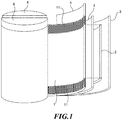
- FIG. 1 is a figure illustrating dimensions and positional relations of an anode foil and a cathode foil of the electric double-layer capacitor according to the present disclosure.
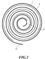
- FIG. 2 is a figure illustrating a method of winding the anode foil and the cathode foil of the electric double-layer capacitor according to the present disclosure.
- An electric double-layer capacitor utilizes an electricity storing function of electric double layers formed on a boundary surface between a polarized electrode and an electrolytic solution, and is formed by housing an element which is a pair of polarized electrodes impregnated with an electrolytic solution in a container.
- the pair of polarized electrodes are an anode foil 1 and a cathode foil 2 formed by integrating a polarized electrode material layer with a current collector, and are separated by a separator to prevent short-circuit.
- This electric double-layer capacitor is of a winding type.
- the element is formed by providing a tab 4 on the anode foil 1 and cathode foil 2 in strip form, and winding the anode foil 1 and the cathode foil 2 with the separator 3 interposed therebetween in a spiral form.
- a direction along the spiral winding is referred to as a strip length direction
- a body height direction of the element is referred to as a strip width direction.
- the anode foil 1 and the cathode foil 2 are wound in a longitudinal direction, in which the longitudinal direction is the strip length direction and a short-length direction is the strip width direction.
- the polarized electrode material layer of the anode foil 1 has a larger width than that of the cathode foil 2.
- the polarized electrode material layer of the anode foil 1 faces the cathode foil 2 via the separator 3
- the polarized electrode material layer of the anode foil 1 protrudes with respect to the cathode foil 2 in the strip width direction. In other words, a side portion of the polarized electrode material layer extending in the strip length direction is exposed. The portion protruding in the polarized electrode material layer of the anode foil 1 does not face the polarized electrode material layer of the cathode foil 2.
- the portion of the polarized electrode material layer of the anode foil 1 protruding with respect to the cathode foil 2 is referred to as an anode-side non-facing portion 11.
- This electric double-layer capacitor has the anode-side non-facing portion 11 extending in the strip width direction of the anode foil 1.
- a strip width of the polarized electrode material layer and a strip width of the current collector can be the same or the current collector can be larger.
- a strip width of the current collector is larger than that of the polarized electrode material layer, when the polarized electrode material layers of the anode foil 1 and the cathode foil 2 have the same width, this is not “larger width” and “protruding”.
- a case in which the strip width of the polarized electrode material layer of the anode foil 1 has a larger width than the strip width of the polarized electrode material layer of the cathode foil 2 is simply expressed as a case in which the strip width of the anode foil 1 has a larger width than the strip width of the cathode foil 2. Also, a case in which the polarized electrode material layer of the anode foil 1 protrudes with respect to the polarized electrode material layer of the cathode foil 2 in the strip width direction is simply expressed as a case in which the anode foil 1 protrudes with respect to the cathode foil 2.
- cathode-side non-facing portions 21 to be described below also refers to a polarized electrode material layer.
- the anode-side non-facing portions 11 are preferably formed at both side portions extending in the strip length direction. That is, the anode foil 1 is preferably disposed to protrude with respect to upper and lower end portions of the cathode foil 2 in the strip width direction. It is presumed that the anode-side non-facing portions 11 can maintain an acidic environment in which deterioration reactions of ⁇ -butyrolactone do not easily progress, but progress of alkalization of an electrolytic solution can be satisfactorily suppressed when the anode-side non-facing portions 11 are present at upper and lower sides in the strip width direction.
- Protrusion amounts of upper and lower portions of the anode-side non-facing portions 11 may be, for example, equivalent to each other.
- the anode foil 1 and the cathode foil 2 may be overlapped with the separator 3 interposed therebetween and wound so that center lines in the strip length direction of the anode foil 1 and the cathode foil 2 are aligned.
- a protrusion amount may be made larger at a lower side in which the electrolytic solution tends to remain.
- the protrusion amounts of the anode-side non-facing portions 11 be each in a range of more than 0 mm and 6.0 mm or less at both side portions. Particularly, when an element having a diameter of 40 mm and a height of 65 mm is used, this range is suitable.
- the anode-side non-facing portions 11 at both side portions are in a range of more than 0 mm and 6.0 mm or less, a capacitance retention rate with aging of the electric double-layer capacitor is high, and aging deterioration of direct current (DC) internal resistance of the electric double-layer capacitor is small.
- DC direct current
- a more preferable range is the protrusion amounts of the anode-side non-facing portions 11 each being in a range of more than 0 mm and less than 6.0 mm at both side portions.
- the protrusion amounts of the anode-side non-facing portions 11 are each in a range of more than 0 mm and less than 5.0 mm at both side portions .
- the anode-side non-facing portions 11 suppress alkalization of the electrolytic solution, within this range, an effect of suppressing alkalization of the electrolytic solution due to the anode-side non-facing portions 11 does not influence the separator 3.
- the widths of the anode-side non-facing portions 11 at both side portions are each in a range of 5.0 mm or more and 6.0 mm or less, coloring of the separator 3 is suppressed by using a separator 3 made of an acid resistant material to be described below.
- the separator 3 may deteriorate unexpectedly.
- the cathode foil 2 is longer compared to the anode foil 1 in the strip length direction.
- both end portions thereof aligned in the strip length direction protrude with respect to the anode foil 1.
- the protruding portions of the cathode foil 2 do not face the anode foil 1.
- the portions of the cathode foil 2 protruding from the anode foil 1 are referred to as the cathode-side non-facing portions 21.
- This electric double-layer capacitor has the cathode-side non-facing portions 21 of the cathode foil 2 in the strip length direction.
- the element is formed such that a beginning side of the first winding and an end side of the last winding are formed by the cathode foil 2. That is, by first winding the cathode foil 2 by one or more turns, winding so that the anode foil 1 to be on an inner peripheral side and the cathode foil 2 to be on an outer peripheral side in the layers of the anode foil 1, the separator 3, and the cathode foil 2, and finally winding the cathode foil 2 past an end portion of the anode foil 1 on the outermost periphery, the cathode foil 2 is made to be positioned on the innermost periphery and on the outermost periphery. Then, the cathode side non-facing portions 21 are provided at the beginning of the winding and at the end of the winding of the cathode foil 2.
- the polarized electrode material is a carbon powder.
- a conductive auxiliary agent may be added to the carbon powder to form a polarized electrode material.
- the carbon powder may be subjected to an activation treatment, such as steam activation, alkali activation, zinc chloride activation, electric field activation, or the like, and an aperture treatment.
- Examples of the carbon powder are as follows.
- natural plant tissues such as a coconut husk, synthetic resins such as phenol, an activated carbon which has raw material thereof derived from fossil fuels such as coal, coke, or pitch, carbon blacks such as Ketjen black, acetylene black, or channel black, carbon nanohorn, amorphous carbon, natural graphite, artificial graphite, graphitized Ketjen black, activated carbon, mesoporous carbon, and the like may be exemplified.
- Ketjen black, acetylene black, natural/artificial graphite, fibrous carbon, or the like can be used, and as fibrous carbon, a fibrous carbon such as carbon nanotubes or carbon nanofibers (hereinafter, CNF) can be exemplified.
- the carbon nanotubes may be a single-walled carbon nanotubes (SWCNT) having one layer of a graphene sheet, may be a multi-walled carbon nanotubes (MWCNT) in which two or more layers of graphene sheets are coaxially rolled up and tube walls thereof are multilayered, and may be mixture thereof.
- a metal having valve action such as aluminum foil, platinum, gold, nickel, titanium, steel, or carbon can be used.
- a shape of the current collector an arbitrary shape such as a film shape, a foil shape, a plate shape, a net shape, an expanded metal shape, or a cylindrical shape can be employed.
- a surface of the current collector may be formed as an irregular surface by an etching treatment or the like, or may be formed as a planar surface. Further, a surface treatment may be performed so that phosphorus is adhered to the surface of the current collector.
- a carbon coating layer containing a conductive agent such as graphite may be provided between the current collector and the polarized electrode layer.
- the carbon coating layer can be formed by applying a conductive agent such as graphite, a slurry containing, for example, a binder or the like on a surface of the current collector and drying.
- a solvent of the electrolytic solution is ⁇ -butyrolactone. Since ⁇ -butyrolactone is easily hydrolyzed by an alkalized cathode foil 2 and becomes an anionic compound, is deposited on the anode foil 1, and shortens a lifetime of the electric double-layer capacitor, ⁇ -butyrolactone is suitable for the present electric double-layer capacitor in which alkalization of the electrolytic solution is suppressed by the anode-side non-facing portions 11.
- a secondary solvent can also be mixed into the ⁇ -butyrolactone.
- secondary solvents include chain sulfones such as ethyl isopropyl sulfone, ethyl methyl sulfone, or ethyl isobutyl sulfone, cyclic sulfones such as sulfolane or 3-methylsulfolane, acetonitrile, 1,2-dimethoxyethane, N-methylpyrrolidone, dimethylformamide, dimethyl sulfoxide, tetrahydrofuran, 2-methyl tetrahydrofuran, 1,3-dioxolane, nitromethane, ethylene glycol, ethylene glycol dimethyl ether, ethylene glycol diethyl ether, water, or a mixture thereof.
- any may be used as long as it can generate quaternary ammonium ions, and one or more kinds selected from various types of quaternary ammonium salts can be exemplified.
- ethyltrimethylammonium BF 4 diethyldimethylammonium BF 4 , triethylmethylammonium BF 4 , tetraethylammonium BF 4 , spiro-(N,N')-bipyrrolidinium BF 4 , methylethylpyrrolidinium BF 4 , ethyltrimethylammonium PF 6 , diethyldimethylammonium PF 6 , triethylmethylammonium PF 6 , tetraethylammonium PF 6 , spiro-(N,N')-bipyrrolidinium PF 6 , tetramethylammonium bis
- a cellulose-based separator As the separator 3, a cellulose-based separator, a synthetic fiber non-woven fabric-based separator, a mixed paper obtained by mixing cellulose and synthetic fibers, a porous film, or the like can be used.
- the cellulose there are Kraft, Manila hemp, esparto, hemp, rayon, and the like.
- the non-woven fabric there are polyester, polyphenylene sulfide, polyethylene terephthalate, polybutylene terephthalate, polyamide, polyimide, fluororesin, polyolefin-based resins such as polypropylene or polyethylene, and fabrics of ceramic, glass, or the like.
- the separator 3 since alkalization of the electrolytic solution is suppressed by the anode-side non-facing portions 11 of the anode foil 1, acid resistant materials such as a synthetic fiber non-woven fabric, glass materials, or the like are used as the separator 3. Even when the widths of the anode-side non-facing portions 11 are each in a range of 5 mm or more and 6 mm or less at both side portions, coloring has not been confirmed in the separator 3 formed of acid resistant materials such as a synthetic fiber non-woven fabric, glass materials, or the like.
- additives may be contained in the electrolytic solution.
- phosphoric acids and derivatives thereof phosphoric acid, phosphorous acid, phosphoric acid esters, phosphonic acids, or the like
- boric acids and derivatives thereof boric acids and derivatives thereof (boric acid, boric oxide acid, boric acid esters, complexes of boron and a compound having a hydroxyl group and/or a carboxyl group, or the like), nitrates (lithium nitrate, or the like), nitro compounds (nitrobenzoic acid, nitrophenol, nitrophenetole, nitroacetophenone, aromatic nitro compounds, or the like), and the like can be exemplified.
- an amount of additives is preferably 10 wt% or less of the entire electrolyte, more preferably 5 wt% or less.
- the electrolyte may contain a gas absorbing agent.
- the absorbing agent for absorbing a gas generated from electrodes there is no particular limitation as long as the gas absorbing agent does not react with any of the components (solvent, electrolytic salt, various types of additive, and the like) of the electrolyte and does not remove (adsorb or the like) them.
- Specific examples thereof include zeolite, silica gel, and the like.
- Example 1 A slurry prepared in the same manner was applied to both surfaces of the current collector foil that had been prepared and was dried to prepare a coated electrode.
- This coated electrode was cut to the dimensions described below to prepare the anode foil 1 and a cathode foil 2 to be used in Example 1.
- a strip width of the anode foil 1 was set to 41.0 mm and a strip width of the cathode foil 2 was set to 40.0 mm so that the anode foil 1 was wider than the cathode foil 2 by 1.0 mm.
- the numerical value of the strip width was a value measured for the layer of the polarized electrode material.
- center lines of the anode foil 1 and the cathode foil 2 extending in the strip length direction were aligned, the anode-side non-facing portions 11 were provided such that the anode foil 1 protruded uniformly 0.5 mm upward and downward with respect to the cathode foil 2 in the strip width direction, the anode foil 1 and the cathode foil 2 with the rayon separator 3 interposed therebetween are overlapped, and a winding type element was formed.
- the cathode foil 2 was made to be the beginning of the first winding and the end of the last winding.
- the cathode foil 2 was caused to protrude in the strip length direction by 30 mm at the beginning of the first winding and to protrude in the strip length direction by 30 mm at the end of the last winding, and the cathode-side non-facing portions 21 were formed in the cathode foil 2.
- the numerical value of the strip length was a value measured for the layer of the polarized electrode material.
- This element was impregnated with an electrolytic solution.
- the electrolytic solution used was 1.5 M methylethylpyrrolidinium BF 4 / ⁇ -butyrolactone solution, the element impregnated with the electrolytic solution was placed in an exterior case of ⁇ 40 ⁇ 65 L and sealed with a sealing body, and an electric double-layer capacitor of Example 1 was prepared.
- a strip width of the anode foil 1 was set to 42.0 mm and a strip width of the cathode foil 2 was set to 40.0 mm so that the anode foil 1 was wider than the cathode foil 2 by 2.0 mm.
- An element was formed such that the anode foil 1 was wound to protrude uniformly 1.0 mm upward and downward with respect to the cathode foil 2 in the strip width direction.
- Other fabrication conditions of the electric double-layer capacitor, such as preparation of a slurry, preparation of a current collector foil, and winding with the cathode foil 2 at the beginning of the first winding and at the end of the last winding, were the same as those in Example 1.
- a strip width of the anode foil 1 was set to 44.0 mm and a strip width of the cathode foil 2 was set to 40.0 mm so that the anode foil 1 was wider than the cathode foil 2 by 4.0 mm.
- An element was formed such that the anode foil 1 was wound to protrude uniformly 2.0 mm upward and downward with respect to the cathode foil 2 in the strip width direction.
- Other fabrication conditions of the electric double-layer capacitor, such as preparation of a slurry, preparation of a current collector foil, and winding with the cathode foil 2 at the beginning of the first winding and at the end of the last winding, were the same as those in Example 1.
- a strip width of the anode foil 1 was set to 46.0 mm and a strip width of the cathode foil 2 was set to 40.0 mm so that the anode foil 1 was wider than the cathode foil 2 by 6.0 mm.
- An element was formed such that the anode foil 1 was wound to protrude uniformly 3.0 mm upward and downward with respect to the cathode foil 2 in the strip width direction.
- Other fabrication conditions of the electric double-layer capacitor, such as preparation of a slurry, preparation of a current collector foil, and winding with the cathode foil 2 at the beginning of the first winding and at the end of the last winding, were the same as those in Example 1.
- a strip width of the anode foil 1 was set to 48.0 mm and a strip width of the cathode foil 2 was set to 40.0 mm so that the anode foil 1 was wider than the cathode foil 2 by 8.0 mm.
- An element was formed such that the anode foil 1 was wound to protrude uniformly 4.0 mm upward and downward with respect to the cathode foil 2 in the strip width direction.
- Other fabrication conditions of the electric double-layer capacitor, such as preparation of a slurry, preparation of a current collector foil, and winding with the cathode foil 2 at the beginning of the first winding and at the end of the last winding, were the same as those in Example 1.
- a strip width of the anode foil 1 was set to 50.0 mm and a strip width of the cathode foil 2 was set to 40.0 mm so that the anode foil 1 was wider than the cathode foil 2 by 10.0 mm.
- An element was formed such that the anode foil 1 was wound to protrude uniformly 5.0 mm upward and downward with respect to the cathode foil 2 in the strip width direction.
- Other fabrication conditions of the electric double-layer capacitor, such as preparation of a slurry, preparation of a current collector foil, and winding with the cathode foil 2 at the beginning of the first winding and at the end of the last winding, were the same as those in Example 1.
- a strip width of the anode foil 1 was set to 52.0 mm and a strip width of the cathode foil 2 was set to 40.0 mm so that the anode foil 1 was wider than the cathode foil 2 by 12.0 mm.
- An element was formed such that the anode foil 1 was wound to protrude uniformly 6.0 mm upward and downward with respect to the cathode foil 2 in the strip width direction.
- Other fabrication conditions of the electric double-layer capacitor, such as preparation of a slurry, preparation of a current collector foil, and winding with the cathode foil 2 at the beginning of the first winding and at the end of the last winding, were the same as those in Example 1.
- the cathode foil 2 was arranged to protrude with respect to the anode foil 1 in the strip width direction.
- a strip width of the anode foil 1 was set to 38.0 mm and a strip width of the cathode foil 2 was set to 40.0 mm so that the cathode foil 2 was wider than the anode foil 1 by 2.0 mm.
- an element was formed such that the cathode foil 2 was wound to protrude uniformly 1.0 mm upward and downward with respect to the anode foil 1 in the strip width direction.
- the cathode foil 2 was arranged to protrude with respect to the anode foil 1 in the strip width direction.
- a strip width of the anode foil 1 was set to 39.0 mm and a strip width of the cathode foil 2 was set to 40.0 mm so that the cathode foil 2 was wider than the anode foil 1 by 1.0 mm.
- an element was formed such that the cathode foil 2 was wound to protrude uniformly 0.5 mm upward and downward with respect to the anode foil 1 in the strip width direction.
- a constant voltage of 2.5 V was applied to the electric double-layer capacitors of Examples 1 to 7 and Comparative examples 1 to 3 at 85°C to measure a discharge capacitance and a DC internal resistance at the initial stage and a discharge capacitance and a DC internal resistance after the elapse of a certain period of time, and a capacitance change rate ⁇ Cap (%) and DC internal resistance ⁇ DCIR (%) were calculated.
- the discharge capacitance and the DC internal resistance were measured again after the elapse of 2000 hours, and the capacitance change rate ⁇ Cap (%) and the DC internal resistance ⁇ DCIR (%) were calculated and are summarized in Table 1 below.
- the discharge capacitance and the DC internal resistance were measured again after the elapse of 1500 hours, and the capacitance change rate ⁇ Cap (%) and the DC internal resistance ⁇ DCIR (%) were calculated and summarized in Table 2 below.
- the "width of the anode-side non-facing portions 11" indicates each protrusion amount at both side portions, and one in which the "width of the anode-side non-facing portions 11" is expressed as a negative number means that the cathode foil 2 protrudes with respect to the anode foil 1 and a protrusion amount thereof is represented by an absolute value of the negative number.
- anode side non-facing portions 11 when extension of the anode side non-facing portions 11 is in a range of more than 0 mm and 6.0 mm or less in width at both sides, an effect of suppressing an increase in DC internal resistance can be satisfactorily obtained.
- a preferable range of the anode-side non-facing portions 11 is more than 0 mm and less than 6.0 mm each at both side portions.
- An electric double-layer capacitor of Example 8 was different from that of Example 6 in which the anode-side non-facing portions 11 were each 5.0 mm at both side portions in that a polyolefin separator 3 which was a non-woven fabric was used, and the other constituents were the same.
- An electric double-layer capacitor of Example 9 was different from that of Example 7 in which the anode-side non-facing portions 11 were each 6.0 mm at both side portions in that a polyolefin separator 3 which was a non-woven fabric was used, and the other constituents were the same.
- Example 3 Width of anode-side non-facing portion
- Example 3 Width of anode-side non-facing portion
- Example 4 3.0mm Rayon No Example 5
- Example 6 5.0mm Rayon Yes
- Example 7 6.0mm Rayon Yes
- Example 8 5.0mm Polyolefin No Example 9 6.0mm Polyolefin No
- Examples 6 and 7 in which the anode-side non-facing portions 11 were respectively set to 5.0 mm to 6.0 mm at both side portions.
- Examples 8 and 9 in which the anode-side non-facing portions 11 were respectively set to 5.0 mm and 6.0 mm at both side portions which are the same as those in Examples 6 and 7, there was no color change on the lower end side of the separator 3.
- the separator 3 of Examples 8 and 9 was an acid resistant non-woven fabric.
- a more preferable range of the anode-side non-facing portions 11 was more than 0 mm and less than 5 mm each at both side portions.
- the widths of the anode-side non-facing portions 11 can be in a range of more than 5 mm and 6 mm or less each at both side portions when the separator 3 is formed of an acid resistant non-woven fabric.
- the anode foil 1 was wound as the beginning of the first winding and as the end of the last winding. That is, by first winding the anode foil 1, winding so that the anode foil 1 is on an inner peripheral side and the cathode foil 2 is on an outer peripheral side in the layers of the anode foil 1, the separator 3, and the cathode foil 2, and finally winding the anode foil 1 one more turn past an end portion of the cathode foil 2 on the outermost periphery, the cathode foil 1 is made to be positioned on the innermost periphery and on the outermost periphery.
- the anode foil 1 was caused to protrude by 30 mm in the strip length direction at the beginning of the first winding and to protrude by 30 mm in the strip length direction at the end of the last winding, and portions not facing the cathode foil 2 is formed at both ends of the anode foil 1 in the strip length direction.
- Other fabrication conditions of the electric double-layer capacitor such as a size of the anode-side non-facing portions 11 or the like were the same as those in Example 1.
- Comparative example 4 in which portions not facing the cathode foil 2 were provided in the anode foil 1 at both ends in the strip length direction showed results in which the capacitance change rate and the DC internal resistance were not satisfactory compared with Example 1 in which the cathode-side non-facing portions 21 were provided in the strip length direction.
Landscapes
- Engineering & Computer Science (AREA)
- Power Engineering (AREA)
- Microelectronics & Electronic Packaging (AREA)
- Chemical & Material Sciences (AREA)
- Chemical Kinetics & Catalysis (AREA)
- Electrochemistry (AREA)
- Electric Double-Layer Capacitors Or The Like (AREA)
Applications Claiming Priority (2)
| Application Number | Priority Date | Filing Date | Title |
|---|---|---|---|
| JP2016136355A JP6816395B2 (ja) | 2016-07-08 | 2016-07-08 | 電気二重層キャパシタ |
| PCT/JP2017/024759 WO2018008713A1 (ja) | 2016-07-08 | 2017-07-06 | 電気二重層キャパシタ |
Publications (2)
| Publication Number | Publication Date |
|---|---|
| EP3483908A1 true EP3483908A1 (de) | 2019-05-15 |
| EP3483908A4 EP3483908A4 (de) | 2020-03-18 |
Family
ID=60912928
Family Applications (1)
| Application Number | Title | Priority Date | Filing Date |
|---|---|---|---|
| EP17824316.8A Withdrawn EP3483908A4 (de) | 2016-07-08 | 2017-07-06 | Elektrischer doppelschichtkondensator |
Country Status (6)
| Country | Link |
|---|---|
| US (1) | US20190148084A1 (de) |
| EP (1) | EP3483908A4 (de) |
| JP (1) | JP6816395B2 (de) |
| KR (1) | KR20190025818A (de) |
| CN (1) | CN109416982A (de) |
| WO (1) | WO2018008713A1 (de) |
Families Citing this family (6)
| Publication number | Priority date | Publication date | Assignee | Title |
|---|---|---|---|---|
| DE102016125733B4 (de) * | 2016-12-27 | 2025-03-20 | Tdk Electronics Ag | Verfahren zur Herstellung eines Kondensators |
| CN115088048A (zh) * | 2020-02-19 | 2022-09-20 | 松下知识产权经营株式会社 | 电解电容器及其制造方法 |
| US12111420B2 (en) | 2020-07-29 | 2024-10-08 | Lg Innotek Co., Ltd. | Mirror with polarizing beam splitter for LIDAR system |
| KR102496185B1 (ko) * | 2021-06-28 | 2023-02-08 | (주) 퓨리켐 | 슈퍼커패시터 및 그 제조 방법 |
| EP4451301A4 (de) * | 2022-03-14 | 2025-10-15 | Nippon Chemicon | Elektrischer doppelschichtkondensator und verfahren zu seiner herstellung |
| CN117497707A (zh) * | 2022-07-26 | 2024-02-02 | 通用汽车环球科技运作有限责任公司 | 用于杂化电容型电极的基于纤维素的纤维型分散剂 |
Family Cites Families (19)
| Publication number | Priority date | Publication date | Assignee | Title |
|---|---|---|---|---|
| US3906582A (en) * | 1974-03-14 | 1975-09-23 | Trico Products Corp | Windshield wiper arm |
| JP3580161B2 (ja) * | 1998-12-15 | 2004-10-20 | トヨタ自動車株式会社 | 発電要素及びその製造方法 |
| JP2001217150A (ja) * | 2000-01-31 | 2001-08-10 | Hitachi Maxell Ltd | 電気二重層キャパシタ |
| JP4887593B2 (ja) * | 2001-09-28 | 2012-02-29 | 日本ケミコン株式会社 | 電解コンデンサ |
| JP4391861B2 (ja) * | 2004-03-23 | 2009-12-24 | 日産ディーゼル工業株式会社 | 電気二重層キャパシタおよびその製造方法 |
| JP2006059912A (ja) * | 2004-08-18 | 2006-03-02 | Nec Tokin Corp | 電気二重層キャパシタ |
| KR100967504B1 (ko) * | 2005-12-01 | 2010-07-07 | 파나소닉 주식회사 | 감김형 전기 이중층 콘덴서 |
| JP2007201118A (ja) * | 2006-01-26 | 2007-08-09 | Matsushita Electric Ind Co Ltd | 巻回形電気二重層コンデンサ |
| JP2007157811A (ja) * | 2005-12-01 | 2007-06-21 | Matsushita Electric Ind Co Ltd | 巻回形電気二重層コンデンサ |
| JP2008182215A (ja) * | 2006-12-25 | 2008-08-07 | Matsushita Electric Ind Co Ltd | 電気二重層キャパシタ |
| KR101153610B1 (ko) * | 2010-06-08 | 2012-06-11 | 삼성전기주식회사 | 2차 전원용 전극 및 이를 포함하는 2차 전원 |
| JP5811893B2 (ja) * | 2011-09-28 | 2015-11-11 | 株式会社豊田自動織機 | 蓄電装置、及び車両 |
| WO2013168755A1 (ja) * | 2012-05-09 | 2013-11-14 | 日立化成株式会社 | 電気化学素子用セパレータ及びその製造方法 |
| WO2014083765A1 (ja) * | 2012-11-28 | 2014-06-05 | 三洋電機株式会社 | 電解コンデンサ |
| JP2014217150A (ja) | 2013-04-25 | 2014-11-17 | 株式会社ニコン | 端末装置、受給電管理システム、受給電管理方法およびプログラム |
| US10147556B2 (en) * | 2014-03-31 | 2018-12-04 | Semiconductor Energy Laboratory Co., Ltd. | Power storage device and electronic device |
| US10256470B2 (en) * | 2014-12-26 | 2019-04-09 | Semiconductor Energy Laboratory Co., Ltd. | Electrode, power storage device, electronic device, and manufacturing method of electrode |
| WO2016157823A1 (ja) * | 2015-03-30 | 2016-10-06 | 日本ケミコン株式会社 | コンデンサおよびその製造方法 |
| CN108352494B (zh) * | 2015-11-06 | 2021-10-26 | 三洋电机株式会社 | 蓄电装置用电极板以及蓄电装置 |
-
2016
- 2016-07-08 JP JP2016136355A patent/JP6816395B2/ja active Active
-
2017
- 2017-07-06 KR KR1020187033715A patent/KR20190025818A/ko not_active Ceased
- 2017-07-06 WO PCT/JP2017/024759 patent/WO2018008713A1/ja not_active Ceased
- 2017-07-06 US US16/310,426 patent/US20190148084A1/en not_active Abandoned
- 2017-07-06 EP EP17824316.8A patent/EP3483908A4/de not_active Withdrawn
- 2017-07-06 CN CN201780038565.0A patent/CN109416982A/zh active Pending
Also Published As
| Publication number | Publication date |
|---|---|
| KR20190025818A (ko) | 2019-03-12 |
| WO2018008713A1 (ja) | 2018-01-11 |
| CN109416982A (zh) | 2019-03-01 |
| JP6816395B2 (ja) | 2021-01-20 |
| JP2018006717A (ja) | 2018-01-11 |
| US20190148084A1 (en) | 2019-05-16 |
| EP3483908A4 (de) | 2020-03-18 |
Similar Documents
| Publication | Publication Date | Title |
|---|---|---|
| EP3483908A1 (de) | Elektrischer doppelschichtkondensator | |
| KR20060050524A (ko) | 전기 이중층 커패시터 | |
| US20030202316A1 (en) | Electric double layer capacitor | |
| US10504661B2 (en) | Hybrid capacitor and separator for hybrid capacitors | |
| US6710999B2 (en) | Electric double layer capacitor | |
| US8274780B2 (en) | Polarizable electrode for electric double layer capacitor and electric double layer capacitor using the same | |
| KR101098240B1 (ko) | 슈퍼커패시터 셀의 제조방법 | |
| EP4224501A1 (de) | Elektrischer doppelschichtkondensator | |
| JP2016197649A (ja) | 電気二重層キャパシタ用セパレータおよび電気二重層キャパシタ | |
| US20090154063A1 (en) | Non-aqueous electrolytic solution for electric double layer capacitor and electric double layer capacitor using the same | |
| JP2016197647A (ja) | ハイブリッドキャパシタ用セパレータおよびハイブリッドキャパシタ | |
| US20210296055A1 (en) | Capacitor electrode foil and capacitor | |
| JP2016197648A (ja) | 電気二重層キャパシタ | |
| EP4451301A1 (de) | Elektrischer doppelschichtkondensator und verfahren zu seiner herstellung | |
| KR102801846B1 (ko) | 고전압 전기이중층커패시터의 제조방법 | |
| US20250210281A1 (en) | Electrochemical device and method for manufacturing electrochemical device | |
| WO2024004740A1 (ja) | 電気二重層キャパシタ及びその製造方法 | |
| WO2025018312A1 (ja) | 電気二重層キャパシタ用電解液、及び電気二重層キャパシタ | |
| JP2025013304A (ja) | 電気二重層キャパシタ用電解液、及び電気二重層キャパシタ | |
| KR101098236B1 (ko) | 슈퍼커패시터 셀 어레이 제조방법 | |
| KR20230101517A (ko) | 전기이중층 커패시터 전해액 및 그 제조방법 | |
| JP2024082269A (ja) | 蓄電デバイス及び蓄電デバイスの製造方法 |
Legal Events
| Date | Code | Title | Description |
|---|---|---|---|
| STAA | Information on the status of an ep patent application or granted ep patent |
Free format text: STATUS: THE INTERNATIONAL PUBLICATION HAS BEEN MADE |
|
| PUAI | Public reference made under article 153(3) epc to a published international application that has entered the european phase |
Free format text: ORIGINAL CODE: 0009012 |
|
| STAA | Information on the status of an ep patent application or granted ep patent |
Free format text: STATUS: REQUEST FOR EXAMINATION WAS MADE |
|
| 17P | Request for examination filed |
Effective date: 20181212 |
|
| AK | Designated contracting states |
Kind code of ref document: A1 Designated state(s): AL AT BE BG CH CY CZ DE DK EE ES FI FR GB GR HR HU IE IS IT LI LT LU LV MC MK MT NL NO PL PT RO RS SE SI SK SM TR |
|
| AX | Request for extension of the european patent |
Extension state: BA ME |
|
| DAV | Request for validation of the european patent (deleted) | ||
| DAX | Request for extension of the european patent (deleted) | ||
| A4 | Supplementary search report drawn up and despatched |
Effective date: 20200219 |
|
| RIC1 | Information provided on ipc code assigned before grant |
Ipc: H01G 11/60 20130101ALI20200213BHEP Ipc: H01G 11/82 20130101ALI20200213BHEP Ipc: H01G 11/52 20130101ALN20200213BHEP Ipc: H01G 11/26 20130101ALI20200213BHEP Ipc: H01G 11/70 20130101AFI20200213BHEP |
|
| STAA | Information on the status of an ep patent application or granted ep patent |
Free format text: STATUS: THE APPLICATION HAS BEEN WITHDRAWN |
|
| 18W | Application withdrawn |
Effective date: 20201216 |