EP4451301A1 - Elektrischer doppelschichtkondensator und verfahren zu seiner herstellung - Google Patents
Elektrischer doppelschichtkondensator und verfahren zu seiner herstellung Download PDFInfo
- Publication number
- EP4451301A1 EP4451301A1 EP23770331.9A EP23770331A EP4451301A1 EP 4451301 A1 EP4451301 A1 EP 4451301A1 EP 23770331 A EP23770331 A EP 23770331A EP 4451301 A1 EP4451301 A1 EP 4451301A1
- Authority
- EP
- European Patent Office
- Prior art keywords
- electrode
- positive electrode
- negative electrode
- potential
- electric double
- Prior art date
- Legal status (The legal status is an assumption and is not a legal conclusion. Google has not performed a legal analysis and makes no representation as to the accuracy of the status listed.)
- Pending
Links
Images






Classifications
-
- H—ELECTRICITY
- H01—ELECTRIC ELEMENTS
- H01G—CAPACITORS; CAPACITORS, RECTIFIERS, DETECTORS, SWITCHING DEVICES, LIGHT-SENSITIVE OR TEMPERATURE-SENSITIVE DEVICES OF THE ELECTROLYTIC TYPE
- H01G11/00—Hybrid capacitors, i.e. capacitors having different positive and negative electrodes; Electric double-layer [EDL] capacitors; Processes for the manufacture thereof or of parts thereof
- H01G11/54—Electrolytes
- H01G11/58—Liquid electrolytes
- H01G11/60—Liquid electrolytes characterised by the solvent
-
- H—ELECTRICITY
- H01—ELECTRIC ELEMENTS
- H01G—CAPACITORS; CAPACITORS, RECTIFIERS, DETECTORS, SWITCHING DEVICES, LIGHT-SENSITIVE OR TEMPERATURE-SENSITIVE DEVICES OF THE ELECTROLYTIC TYPE
- H01G11/00—Hybrid capacitors, i.e. capacitors having different positive and negative electrodes; Electric double-layer [EDL] capacitors; Processes for the manufacture thereof or of parts thereof
- H01G11/04—Hybrid capacitors
-
- H—ELECTRICITY
- H01—ELECTRIC ELEMENTS
- H01G—CAPACITORS; CAPACITORS, RECTIFIERS, DETECTORS, SWITCHING DEVICES, LIGHT-SENSITIVE OR TEMPERATURE-SENSITIVE DEVICES OF THE ELECTROLYTIC TYPE
- H01G11/00—Hybrid capacitors, i.e. capacitors having different positive and negative electrodes; Electric double-layer [EDL] capacitors; Processes for the manufacture thereof or of parts thereof
- H01G11/22—Electrodes
- H01G11/24—Electrodes characterised by structural features of the materials making up or comprised in the electrodes, e.g. form, surface area or porosity; characterised by the structural features of powders or particles used therefor
-
- H—ELECTRICITY
- H01—ELECTRIC ELEMENTS
- H01G—CAPACITORS; CAPACITORS, RECTIFIERS, DETECTORS, SWITCHING DEVICES, LIGHT-SENSITIVE OR TEMPERATURE-SENSITIVE DEVICES OF THE ELECTROLYTIC TYPE
- H01G11/00—Hybrid capacitors, i.e. capacitors having different positive and negative electrodes; Electric double-layer [EDL] capacitors; Processes for the manufacture thereof or of parts thereof
- H01G11/22—Electrodes
- H01G11/26—Electrodes characterised by their structure, e.g. multi-layered, porosity or surface features
- H01G11/28—Electrodes characterised by their structure, e.g. multi-layered, porosity or surface features arranged or disposed on a current collector; Layers or phases between electrodes and current collectors, e.g. adhesives
-
- H—ELECTRICITY
- H01—ELECTRIC ELEMENTS
- H01G—CAPACITORS; CAPACITORS, RECTIFIERS, DETECTORS, SWITCHING DEVICES, LIGHT-SENSITIVE OR TEMPERATURE-SENSITIVE DEVICES OF THE ELECTROLYTIC TYPE
- H01G11/00—Hybrid capacitors, i.e. capacitors having different positive and negative electrodes; Electric double-layer [EDL] capacitors; Processes for the manufacture thereof or of parts thereof
- H01G11/84—Processes for the manufacture of hybrid or EDL capacitors, or components thereof
- H01G11/86—Processes for the manufacture of hybrid or EDL capacitors, or components thereof specially adapted for electrodes
-
- H—ELECTRICITY
- H01—ELECTRIC ELEMENTS
- H01G—CAPACITORS; CAPACITORS, RECTIFIERS, DETECTORS, SWITCHING DEVICES, LIGHT-SENSITIVE OR TEMPERATURE-SENSITIVE DEVICES OF THE ELECTROLYTIC TYPE
- H01G11/00—Hybrid capacitors, i.e. capacitors having different positive and negative electrodes; Electric double-layer [EDL] capacitors; Processes for the manufacture thereof or of parts thereof
- H01G11/22—Electrodes
- H01G11/26—Electrodes characterised by their structure, e.g. multi-layered, porosity or surface features
-
- Y—GENERAL TAGGING OF NEW TECHNOLOGICAL DEVELOPMENTS; GENERAL TAGGING OF CROSS-SECTIONAL TECHNOLOGIES SPANNING OVER SEVERAL SECTIONS OF THE IPC; TECHNICAL SUBJECTS COVERED BY FORMER USPC CROSS-REFERENCE ART COLLECTIONS [XRACs] AND DIGESTS
- Y02—TECHNOLOGIES OR APPLICATIONS FOR MITIGATION OR ADAPTATION AGAINST CLIMATE CHANGE
- Y02E—REDUCTION OF GREENHOUSE GAS [GHG] EMISSIONS, RELATED TO ENERGY GENERATION, TRANSMISSION OR DISTRIBUTION
- Y02E60/00—Enabling technologies; Technologies with a potential or indirect contribution to GHG emissions mitigation
- Y02E60/13—Energy storage using capacitors
Definitions
- the present disclosure relates to a wound-type electric double layer capacitor including ⁇ -butyrolactone as a solvent, and a manufacturing method thereof.
- An electric double layer capacitor is formed by housing an element which is a pair of polarizable electrodes impregnated with electrolytic solution in a container, and utilizes electricity storage action of an electric double layer formed at an interface of the polarizable electrode and the electrolytic solution.
- the electric double layer capacitor is advantageous in having long lifetime with little deterioration of electrode active material due to repeated charging and discharging.
- activated carbon powder is used for polarizable electrode material
- metal with valve action such as aluminum is used for a current collector
- aprotic electrolytic solution is used as the electrolytic solution.
- Quaternary ammonium salt is mainly used for an electrolyte of the electrolytic solution.
- carbonate compounds such as polypropylene carbonate and carboxylic acid ester compounds such as ⁇ -butyrolactone are used for a solvent of the electrolytic solution (for example, refer Patent Document 1).
- Patent Document 1 JP2001-217150A
- the carbonate solvent generates carbon monoxide gas due to decomposition of the solvent, which may increase internal pressure of the electric double layer capacitor.
- ⁇ -butyrolactone is advantageous in that gas due to decomposition does not occur.
- the capacitance over time of the electric double layer capacitor using ⁇ -butyrolactone tends to show larger deterioration.
- the present disclosure is proposed to address the above-described problem.
- the objective is to provide an electric double layer capacitor and a manufacturing method thereof that suppress the deterioration of the capacitance over time even when ⁇ -butyrolactone is used as the solvent.
- an electric double layer capacitor of embodiments of the present disclosure is an electric double layer capacitor formed by impregnating an element which is a positive electrode and a negative electrode wound via a separator with electrolytic solution, in which the electrolytic solution contains ⁇ -butyrolactone as a solvent, and capacitance Cp of the positive electrode and capacitance Cn of the negative electrode are Cp>Cn.
- a capacity ratio Cp:Cn between the capacitance Cp of the positive electrode and the capacitance Cn of the negative electrode may be 1.2:1 to 1.6:1.
- the electrode potential of the positive electrode and the electrode potential of the negative electrode fall within the potential window of ⁇ -butyrolactone even if the withstand voltage of the electric double layer capacitor is 2.7 V or more. If the capacity ratio exceeds beyond this range, the electrode potential of the negative electrode deviates from the potential window of ⁇ -butyrolactone. If the capacity ratio is narrower than this range, the electrode potential of the positive electrode deviates from the potential window of ⁇ -butyrolactone.
- the positive electrode and the negative electrode each include a current collector and a polarizable electrode layer on the current collector, and thickness of the polarizable electrode layer of the positive electrode is 0.9 to 1.3 times thicker than thickness of the polarizable electrode layer of the negative electrode.
- the capacity ratio Cp:Cn between the capacitance Cp of the positive electrode and the capacitance Cn of the negative electrode easily falls within 1.2:1 to 1.6:1.
- the electrode potential (vs Ag/Ag+) of the positive electrode and the electrode potential (vs Ag/Ag+) of the negative electrode within the potential window of ⁇ -butyrolactone, the deterioration over time of the capacitance of the electric double layer capacitor can be suppressed even if the withstand voltage of the electric double layer capacitor is increased.
- the electrode potential (vs Ag/Ag+) of the positive electrode may be +0.71 V to +0.62 V
- the electrode potential (vs Ag/Ag+) of the negative electrode may be -1.99 V to -2.08 V.
- the electrode potential (vs Ag/Ag+) of the positive electrode may be +0.71 V to +0.45 V
- the electrode potential (vs Ag/Ag+) of the negative electrode may be -1.99 V to -2.25 V.
- a strip-length of the positive electrode is longer than the negative electrode, the element is wound so that the positive electrode is positioned at the innermost and outermost circumference, and the positive electrode may protrude from the negative electrode at beginning and end of winding in the strip-length direction.
- the capacitance Cp of the positive electrode becomes larger than the capacitance Cn of the negative electrode, and the electrode potential of the positive electrode and the electrode potential of the negative electrode shift in the lower direction. Therefore, the electrode potential of the positive electrode and the electrode potential of the negative electrode further easily fall within the potential window of ⁇ -butyrolactone, and ⁇ -butyrolactone is electrochemically stabilized.
- a manufacturing method of the electric double layer capacitor is an aspect of the present disclosure, and the method including: a positive electrode formation process of forming a positive electrode with electrode potential (vs Ag/Ag+) of +0.71 v to +0.61 V, a negative electrode formation process of forming a negative electrode with electrode potential (vs Ag/Ag+) of -1.99 V to -2.08 V, an element formation process of winding the positive electrode and the negative electrode via a separator to form an element, and an electrolytic solution impregnation process of impregnating the element with electrolytic solution containing ⁇ -butyrolactone as a solvent.
- the electrode potential (vs Ag/Ag+) of the positive electrode may be +0.71 V to +0.45 V
- the electrode potential (vs Ag/Ag+) of the negative electrode may be -1.99 V to -2.25 V.
- the electrode potential of the positive electrode and the electrode potential of the negative electrode easily fall within the potential window of ⁇ -butyrolactone, and the deterioration over time of the capacitance of the electric double layer capacitor can be suppressed.
- An electric double layer capacitor is a passive element that utilizes electricity storage action formed at an interface of a polarizable electrode and electrolytic solution and stores and discharges electric charge by capacitance.
- the element of this electric double layer capacitor includes a positive electrode, a negative electrode, a separator, and electrolytic solution, and is a wound-type.
- the positive electrode and the negative electrode face each other via the separator.
- the electrolytic solution is filled in voids of the capacitor element.
- This element is housed in a casing and is sealed with a sealing body.
- the casing is a cylinder with a bottom to house the element and, for example, is made of aluminum.
- the sealing body is attached to an opening of the casing by a crimping process and seals the opening of the casing.
- a lead terminal is connected to the positive electrode and the negative electrode.
- An external terminal that leads to the outside is attached to the sealing body.
- the lead terminal connected to the positive electrode and the negative electrode is electrically connected to the external terminal of the sealing body, so that the electric double layer capacitor can be implemented on a circuit.
- the lead terminal connected to the positive electrode and the negative electrode is lead to the outside through a through hole.
- a solvent of the electrolytic solution is ⁇ -butyrolactone.
- a voltammogram by the cyclic voltammetry of ⁇ -butyrolactone is shown in Fig. 1 .
- the cyclic voltammogram of ⁇ -butyrolactone is measured as follows. That is, an activated carbon electrode with area of 1.5 cm ⁇ 1.5 cm and coating thickness of 29 um is used for a working electrode, an activated carbon electrode with area of 1.5 cm ⁇ 10 cm and coating thickness of 29 um is used for a counter electrode, and Ag/Ag+ reference electrode is used for a reference electrode. Solution of 1 mol of triethylmethylammonium BF4 per 1L of ⁇ -butyrolactone is used as measurement solution.
- Potential scanning is started from immersion potential to 1 V on the positive side from the immersion potential. Potential scanning speed is 0.5 mV/s. Furthermore, the potential scanning is started from immersion potential to -2.6 V on the negative side from the immersion potential. Potential scanning speed is 0.5 mV/s.
- ⁇ -butyrolactone does not exchange electrons, and the plane region near current of zero and inclination of zero falls within +0.71 V to -2.08 V.
- the dotted line is the minimum value in the nagative side and the maximum value in the positive side. That is, a potential window of ⁇ -butyrolactone is +0.71 V to -2.08 V.
- An electrolyte of the electrolytic solution may be any if quaternary ammonium ions can be produced and may be one or more selected from various quaternary ammonium salt.
- Cations may be tetramethylammonium, ethyltrimethylammonium, tetraethylammonium, triethylmethylammonium, diethyldimethylammonium, methylethylpyrrolidinium, spirobipyrrolidinium, and anions may be BF 4 -, PF 6 -, ClO 4 -, AsF 6 -, SbF 6 -, AlCl 4 -, or RfSO 3 -, (RfSO 2 ) 2 N-, and RfCO 2 - (Rf is a fluoroalkyl group with 1 to 8 carbon).
- the quaternary ammonium salt may be tetramethylammonium BF 4 , ethyltrimethylammonium BF 4 , diethyldimethylammonium BF 4 , triethylmethylammonium BF 4 , tetraethylammonium BF 4 , spirobipyrrolidinium BF 4 , methylethylpyrrolidinium BF 4 , tetramethylammonium PF 6 , ethyltrimethylammonium PF 6 , diethyldimethylammonium PF 6 , triethylmethylammonium PF 6 , tetraethylammonium PF 6 , spirobipyrrolidinium PF 6 , methylethylpyrrolidinium PF 6 , tetramethylammonium bis(oxalate)borate, ethyltrimethylammonium bis(oxalate)borate
- an additive may be phosphoric acid and derivatives thereof (phosphoric acid, phosphorus acid, phosphate esters, and phosphonic acid, etc.), boric acid and derivatives thereof (boric acid, boric oxides, borate esters, complex of boron and compounds with hydroxyl group and/or carboxyl group, etc.), nitrates (lithium nitrate, etc.), nitro compounds (nitrobenxzoic acid, nitrophenol, nitrophenetol, nitroacetophenone, aromatic nitro compounds, etc.).
- the positive electrode and the negative electrode is mainly formed by a current collector and a polarizable electrode layer.
- the current collector is metal such as aluminum foil, platinum, gold, nickel, titanium, and steel, etc.
- a shape of the current collector may be any shape such as a film-shape, a foil-shape, a plate-shape, a netshape, an expand-metal-shape, and a cylinder-shape, etc.
- a surface of the current collector may be an uneven surface such as by etching, or may be a plain surface.
- the polarizable electrode layer mainly contains activated carbon.
- Source material for the activated carbon is derived from natural plant tissues such as coconut hemp, synthetic resin such as phenols, fossil-fuel based material such as coal, coke, and pitch, and activation treatment such as steam activation, alkaline activation, zinc chloride activation, or electric field activation, and opening treatment may be performed.
- the positive electrode has capacitance Cp.
- the negative electrode has capacitance Cn.
- the polarizable electrode layer is adjusted so that Cp>Cn, in which the capacitance Cp of the positive electrode is larger than the capacitance Cn of the negative electrode.
- the capacitance Cp of the positive electrode and the capacitance Cn of the negative electrode is measured as follows. That is, the capacitance is measured by cutting out a test piece with predefined area, immersing the test piece in capacitance measurement solution in a glass measurement tank with a platinum plate as the counter electrode, and using the capacitance meter.
- the predefined area is 1 cm 2
- the capacitance measurement solution is aqueous solution of ammonium pentaborate at 30 °C
- the capacitance meter is a potentiostat and a frequency response analyzer, an electrochemical impedance analyzer, or LCR meter, and the like
- DC bias voltage is 1.5 V
- AC current is 0.5 Vrms, as the measurement condition.
- electrode potential (vs. Ag/Ag+QRE) of the positive electrode and electrode potential (vs. Ag/Ag+QRE) of the negative electrode shift in the lower direction and easily fall within a potential window of ⁇ -butyrolactone. Therefore, ⁇ -butyrolactone is electrochemically stabilized, and even if withstand voltage of the electric double layer capacitor is increased, decomposition reaction current of ⁇ -butyrolactone is small and the deterioration over time of the capacitance of the electric double layer capacitor can be suppressed.
- the capacity ratio Cp:Cn between the capacitance Cp of the positive electrode and the capacitance Cn of the negative electrode is 1.2:1 to 1.6:1.
- the electrode potential of the positive electrode and the electric double layer capacitor of the negative electrode fall within the potential window of ⁇ -butyrolactone even when the withstand voltage of the electric double layer capacitor is 2.7 V or more. If the capacity ratio exceeds beyond this range, the electrode potential of the negative electrode deviates from the potential window of ⁇ -butyrolactone. If the capacity ratio is narrower than this range, the electrode potential of the positive electrode deviates from the potential window of ⁇ -butyrolactone.
- the electrode potential (vs. Ag/Ag+QRE) of the positive electrode is +0.71 V
- the electrode potential (vs. Ag/Ag+QRE) of the negative electrode is -1.99 V
- both electrode potential fall within the potential window of ⁇ -butyrolactone.
- the electrode potential (vs. Ag/Ag+QRE) of the positive electrode is +0.62 V
- the electrode potential (vs. Ag/Ag+QRE) of the negative electrode is -2.08 V, and both electrode potential fall within the potential window of ⁇ -butyrolactone.
- the electrode potential (vs. Ag/Ag+QRE) of the positive electrode falls within +0.71 V to +0.45 V and the electrode potential (vs. Ag/Ag+QRE) of the negative electrode falls within -1.99 V to -2.25 V, even after the electric double layer capacitor has been used for a long time.
- the electrode potential of the positive electrode and the electrode potential of the negative electrode fall within these range, keen deterioration of the capacitance can be prevented, and the deterioration over time can be suppressed.
- a long time is a timing after applying DC voltage of 2.7 V under temperature environment of 65 °C and 2000 hours have elapsed,
- the potential of the positive electrode and the potential of the negative electrode are measured as follows. That is, the lead capacitor is immersed in the electrolytic solution of 1 mol of triethylmethylammonium BF4 per 1L of ⁇ -butyrolactone. The capacitor element is impregnated with said electrolytic solution. The reference electrode (Ag/Ag+) is positioned at the outermost circumference of the capacitor element. Then, for example, the capacitor element is charged to 2.7 V at 5 A and is held for 4 hours. The potential of the positive electrode and the negative electrode relative to the reference electrode held for 4 hours is the polarization potential.
- the capacitance Cp of positive electrode and the capacitance Cn of the negative electrode can be adjusted by thickness of each polarizable electrode layer. That is, to achieve the capacity ratio Cp:Cn of 1.2:1 to 1.6:1 between the capacitance Cp of the positive electrode and the capacitance Cn of the negative electrode, it is preferable to adjust thickness of the polarizable electrode layer of the positive electrode to be 0.9 to 1.3 times thicker than thickness of the polarizable electrode layer of the negative electrode. In other word, it is preferable that thickness ratio Tp:Tn between the thickness Tp of the polarizable electrode layer of the positive electrode and the thickness Tn of the polarizable electrode layer of the negative electrode is 0.9:1 to 1.3:1.
- the polarizable electrode layer may be formed by applying slurry of activated carbon and a binder on the current collector by doctor blading, and the like, and drying the slurry to form the electrode.
- a mixture of carbon material and the binder may be formed into a sheet and may be pressure-bonded on the current collector.
- the binder may be rubber such as fluorine-based rubber, diene-based rubber, and styrenebased rubber, fluorine-containing polymers such as polytetrafluoroethylene and polyvinylidene difluoride, cellulose such as carboxymethyl cellulose and nitrocellulose, and others such as polyolefin resin, polyimide resin, acryl resin, nitrile resin, polyester resin, phenol resin, polyvinyl acetate resin, polyvinyl alcohol resin, and epoxy resin, etc. These binders may be used in single or in combination of two or more.
- the polarizable electrode layer may include conductive aid.
- the conductive aid may be carbon black such as Ketjen black, acetylene black, and channel black, carbon nanohorn, amorphous carbon, natural graphite, artificial graphite, graphitized Ketjen black, mesoporous carbon, carbon nanotube, and carbon nanofiber, etc.
- the carbon nanotube may be single-walled carbon nanotube (SWCNT) with a single layer of a graphene sheet, or multiwalled carbon nanotube (MWCNT) in which two or more layers of graphene sheets are curled up on a same axis and a tube wall forms multiple layers.
- phosphorus may be adhered on a surface of the current collector to suppress hydration and oxidation of the current collector.
- the current collector is immersed in aqueous solution of phosphoric acid or phosphate.
- a carbon coating layer including the conductive aid such as graphite may be provided between the current collector and the polarizable electrode layer.
- Such positive electrode and negative electrode have a long strip-shape and are wound spirally via the separator.
- the direction along the spiral is the strip-length direction, and generally, the positive electrode and the negative electrode is wound along the length direction, which is the strip-length direction.
- Fig. 2 is a schematic diagram illustrating a winding method of the positive electrode and the negative electrode, in which the solid line is the positive electrode and the dotted line is the negative electrode.
- the positive electrode is longer than the negative electrode in the strip-length direction when comparing the lengths of the positive electrode and the negative electrode in the strip-length direction, and the electrodes are wound so that the positive electrode is positioned in the innermost and outermost circumference and forms a non-facing portion where the beginning and end of the winding of the positive electrode do not face the negative electrode. That is, the element is formed so that the positive electrode is at the beginning and end of the winding.
- negative electrode foil is positioned in the innermost and outermost circumference.
- the capacitance Cp of the positive electrode becomes larger than the capacitance Cn of the negative electrode, and the electrode potential of the positive electrode and the electrode potential of the negative electrode can be shifted in the lower direction. Therefore, the electrode potential of the positive electrode and the electrode potential of the negative electrode further easily fall within the potential window of ⁇ -butyrolactone, and ⁇ -butyrolactone is electrochemically stabilized.
- the separator prevents a contact between the positive electrode foil and the negative electrode.
- the separator includes cellulose such as kraft, Manila hemp, esparto, hemp, rayon, and mixed papers thereof, polyester resin such as polyethylene terephthalate, polybutylene terephthalate, polyethylene naphthalate, and derivatives thereof, polytetrafluoroethylene resin, polyvinylidene fluoride resin, vinylon resin, polyamide resin such as aliphatic polyamide, semi-aromatic polyamide, and total aromatic polyamide, polyimide resin, polyethylene resin, polypropylene resin, trimethylpentene resin, polyphenylene sulfide resin, acrylic resin and the like, and the resin may be used in single or in combination.
- the electric double layer capacitor is manufactured through a positive electrode formation process, a negative electrode formation process, an element formation process, and an electrolytic solution impregnation process.
- the polarizable electrode layer is formed on the current collector and is adjusted to form the positive electrode with the electrode potential (vs. Ag/Ag+) of +0.71 V to + 0.62 V.
- the polarizable electrode layer is formed on the current collector and is adjusted to form the negative electrode with the electrode potential (vs. Ag/Ag+) of -1.99 V to - 2.08 V.
- the positive electrode and the negative electrode are wound spirally via the separator.
- the positive electrode by winding the positive electrode one round or more in advance, then winding layers of positive electrode, the separator, and the negative electrode so that the positive electrode is in the inner circumferential side and the negative electrode is in the outer circumferential side, and finally winding the positive electrode at the outermost circumference so as to extend beyond the end of the negative electrode, negative electrode foil is positioned in the innermost and outermost circumference.
- the element is impregnated with the electrolytic solution containing ⁇ -butyrolactone as the main solvent.
- the impregnation may be performed under depressurized condition.
- the element is housed in the casing, and the casing is sealed by the sealing body.
- the electric double layer capacitors with the withstand voltage of 2.7 V of the examples 1 to 5 and the comparative example 1 were produced, as follows That is, steam-activated activated carbon, carbon black, carboxymethyl cellulose as a dispersant, SBR emulsion as a binder, and pure water were mixed to obtain a slurry. Furthermore, current collector foil was produced by immersing the etched aluminum foil in phosphoric acid aqueous solution to adhere phosphorus on the surface thereof, and applying coating material including graphite on the surface of the foil to form the carbon coating layer on both surface of the aluminum foil. The similarly produced slurry was applied and dried on both surface of the produced current collector to produce the positive electrode and the negative electrode with the same stripwidth.
- the positive electrode and the negative electrode were overlaid via the rayon separator along the center lines thereof extending in the strip-length direction, to produce the wound-type element.
- the beginning and end of the winding was the positive electrode.
- the positive electrode was wound in advance, the layers of positive electrode, the separator, and the negative electrode were wound so that the positive electrode was in the inner circumferential side and the negative electrode was in the outer circumferential side, and the positive electrode was wound at the outermost circumference so as to extend beyond the end of the negative electrode. Therefore, the non-facing portion where the positive electrode did not face the negative electrode was formed in the beginning and end of the positive electrode.
- the element was impregnated with the electrolytic solution.
- 1.0 M of triethylmethylammonium BF 4 was used for the solute of the electrolytic solution.
- 1.0 M indicates a number of moles (mol/L) of the electrolyte relative to 1L of the electrolytic solution.
- the solvent of the electrolytic solution is ⁇ -butyrolactone.
- the element was impregnated with this electrolytic solution, and the element impregnated with the electrolytic solution was housed and sealed in the ⁇ 18 ⁇ 50L casing by the sealing body.
- the electric double layer capacitors of the examples 1 to 5 and the comparative example 1 had different coating thickness of the polarizable electrode layer, different length of the positive electrode and the negative electrode, and thereby different capacity ratio Cp:Cn between the capacitance Cp of the positive electrode and the capacitance Cn of the negative electrode.
- the capacity ratio Cp:Cn of the comparative example 1 was 1.00:1, and the capacitance of the positive electrode and the negative electrode in the comparative example 1 was the same.
- the capacity ratio between the capacitance Cp of the positive electrode and the capacitance Cn of the negative electrode in the examples 1 to 5 was Cp>Cn, the capacitance Cp of the positive electrode was larger than the capacitance Cn of the negative electrode.
- the capacity ratio Cp:Cn of the example 1 was 1.20:1
- the capacity ratio Cp:Cn of the example 2 was 1.28:1
- the capacity ratio Cp:Cn of the example 3 was 1.34:1
- the capacity ratio Cp:Cn of the example 4 was 1.55:1
- the capacity ratio Cp:Cn of the example 5 was 1.90:1
- the amount of activated carbon in the non-facing portion of the positive electrode was the same in the examples 1 to 5 and the comparative example 1, and was 6 wt% relative to the total amount of activated carbon applied on the positive electrode.
- the electrode potential V (vs. Ag/Ag+) of the positive electrode and the negative electrode of the electric double layer capacitors of the examples 1 to 5 and the comparative example 1 was measured.
- the measurement method for the electrode potential V was as follows. That is, the elements of the examples 1 to 5 and the comparative example 1 were immersed in the electrolytic solution. The elements were also impregnated with the electrolytic solution.
- the reference electrode (Ag/Ag+) was positioned at the outermost circumference of the elements. Then, the elements were charged up to 2.7 V at 5 A for 4 hours. Potential of the positive electrode and the negative electrode relative to the reference electrode after being held for 4 hours was the polarization potential.
- Example 1 Capacity Ratio (Cp:Cn) Electrode Potential of Positive Electrode (vs. Ag/Ag+) Electrode Potential of Negative Electrode (vs. Ag/Ag+) Comparative Example 1 1.00:1 0.77 -1.93
- Example 1 1.20:1 0.71 -1.99
- Example 2 1.28:1 0.68 -2.02
- Example 3 1.34:1 0.69 -2.01
- Example 4 1.55:1 0.62 -2.08
- Example 5 1.90:1 0.51 -2.19
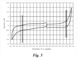
- Figs. 3 to 8 illustrate the cyclic voltammogram of ⁇ -butyrolactone and the positive and negative electrode potential of the comparative example 1.
- Figs. 4 to 8 illustrates the cyclic voltammogram of ⁇ -butyrolactone and the positive and negative electrode potential of each example.
- the dotted line is the minimum value at the negative side and the maximum value at the positive side
- the solid line is the electrode potential of the positive electrode and the electrode potential of the negative electrode.
- the potential difference between the negative electrode and the positive electrode was all 2.7 V, and the electric double layer capacitors with the withstand voltage of 2.7 V were produced.
- the comparative example 1 in which the capacitance at the positive electrode and the negative electrode was the same although the electrode potential of the negative electrode was within the potential window of ⁇ -butyrolactone, the electrode potential of the positive electrode significantly exceeded beyond the upper limit of the potential window of ⁇ -butyrolactone and clearly belonged to the range in which the inclination had rapidly changed.
- the electrode potential of the positive electrode and the electrode potential of the negative electrode were approximately within the potential window of ⁇ -butyrolactone.
- the electrode potential of the negative electrode was at a position much away from the lower limit of the potential window of ⁇ -butyrolactone.
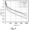
- the constant voltage of 2.7 V was applied to the electric double layer capacitors of the examples 1 to 5 and the comparative examples 1 and 8 at 65 °C, and the initial discharge capacity and the discharge capacity after each time had elapsed was measured, to calculate the capacity change rate ⁇ Cap (%).
- the capacitance of the electric double layer capacitors of the examples 1 to 5 and the comparative example 1 was measured according to the constant current discharge method. That is, the electric double layer capacitor was charged for 20 minutes by applying constant voltage of 2.7 V under the temperature environment of 20 °C. After the charging had been completed, the discharging was performed promptly at the constant current I, and the required time T spent for the voltage to fall from measurement start voltage to measurement end voltage 1.35 V excluding IR drop was measured. Then, the capacity (F) was calculated from a product of the constant current I and the time T, and a difference (V) between the measurement start voltage and the measurement end voltage. The measurement was performed four times and the average value was taken,
- Fig. 9 is a graph comparing the change over time of the capacity change rate ⁇ Cap of the electric double layer capacitors of the examples 4 and 5 and the comparative example 1. Note that, in Fig. 9 , the graph with X-plots indicates the comparative example 1, the graph with square plots indicates the example 4, and the graph with triangle plots indicates the example 5.
- the inclination of the capacitance change rate ⁇ cap in the time range Ta from 1000 hours to 2000 hours elapsed was comparable to the inclination of the capacitance change rate ⁇ cap in the time range Tb from 500 hours to 1000 hours after the constant voltage was applied, and the electric double layer capacitor was highly reliable also in the range of 1000 hours to 2000 hours.
- the capacity Cp:Cn of the positive electrode and the negative electrode was 1.20:1 to 1.60:1
- the inclination of the capacitance change rate ⁇ cap in the time range Ta from 1000 hours to 2000 hours elapsed was comparable to the inclination of the capacitance change rate ⁇ cap in the time range Tb from 500 hours to 1000 hours after the constant voltage was applied, and the electric double layer capacitor was highly reliable also in the range of 1000 hours to 2000 hours.
- the thickness ratio Tp:Tn between the thickness Tp of the polarizable electrode layer of the positive electrode and the thickness Tn of the polarizable electrode layer of the negative electrode was within this range, the capacity ratio Cp:Cn between the capacitance Cp of the positive electrode and the capacitance Cn of the negative electrode could be adjusted within 1.2:1 to 1.6:1.
- the constant voltage of 2.7 V was applied to the electric double layer capacitors of the examples 1 to 5 and the comparative example 1 at 65 °C, and the initial discharge capacity and the discharge capacity after each time had elapsed, and the electrode potential of the positive electrode and the electrode potential of the negative electrode at each time had elapsed were measured. The results are shown in the table 4.
- Fig. 10 illustrates the change over time of the electrode potential of the positive electrode of the examples 2, 4 and 5 and the comparative example 1.
- the graph with X-plots indicates the comparative example 1
- the graph with circular plots indicates the example 2
- the graph with square plots indicates the example 4
- the graph with triangle plots indicates the example 5.
- the electrode potential (vs Ag/Ag+) of the positive electrode at 2000 hours was below +0.71 V to + 0.45 V.
- the examples 1 to 4 were within +0.71 V to + 0.45 V even after 2000 hours had elapsed. Therefore, it was observed that, in the electric double layer capacitors of the examples 1 to 4, the inclination of the capacity change rate ⁇ Cap after 2000 hours had elapsed did not change, and the deterioration of the capacity was suppressed.
- the electric double layer capacitor of the examples 6 was produced.
- the strip-length of the negative electrode was longer than the positive electrode, contrary to the example 2. Therefore, in the example 6, the element was wound so that the negative electrode was positioned at the innermost and outermost circumference, and the negative electrode protruded from the positive electrode at beginning and end of winding.
- the example 6 was produced by the same method, the same condition, the same composition, and the same structure as the example 2, and the capacity ratio between the capacitance Cp of the positive electrode and the capacitance Cn of the negative electrode was 1.28:1 as same as the example 2.
- the coating thickness of the positive and negative polarizable electrode layer was 39 um
- the strip-length of the polarizable electrode was 665 mm
- the strip-length of the negative electrode was 625 um
- the coating thickness of the polarizable electrode layer of the polarizable electrode was 42 um
- the coating thickness of the polarizable electrode layer of the negative electrode was 37 um
- the strip-length of the polarizable electrode was 620 mm
- the strip-length of the negative electrode was 663 um.
- Fig. 11 is a graph illustrating the change over time of the capacity change rate ⁇ Cap (%) of the electric double layer capacitors of the examples 2 and 6. Note that in the graph, the solid line indicates the example 2, and the broken line indicates the example 6.
- the capacity change rate ⁇ Cap of the electric double layer capacitors of the examples 2 was excellent than the electric double layer capacitor of the example 6. That is, it was observed that, by making the strip-length of the positive electrode longer than that of the negative electrode, winding the positive electrode to be positioned at the innermost and outermost circumference, and making the positive electrode to protrude from the negative electrode at beginning and end of winding in the strip-length direction, the capacity change rate ⁇ Cap of the electric double layer capacitor could be further improved.
Landscapes
- Engineering & Computer Science (AREA)
- Power Engineering (AREA)
- Microelectronics & Electronic Packaging (AREA)
- Chemical & Material Sciences (AREA)
- Chemical Kinetics & Catalysis (AREA)
- Electrochemistry (AREA)
- Materials Engineering (AREA)
- Manufacturing & Machinery (AREA)
- Electric Double-Layer Capacitors Or The Like (AREA)
Applications Claiming Priority (2)
| Application Number | Priority Date | Filing Date | Title |
|---|---|---|---|
| JP2022039298 | 2022-03-14 | ||
| PCT/JP2023/006799 WO2023176372A1 (ja) | 2022-03-14 | 2023-02-24 | 電気二重層キャパシタ及びその製造方法 |
Publications (2)
| Publication Number | Publication Date |
|---|---|
| EP4451301A1 true EP4451301A1 (de) | 2024-10-23 |
| EP4451301A4 EP4451301A4 (de) | 2025-10-15 |
Family
ID=88023461
Family Applications (1)
| Application Number | Title | Priority Date | Filing Date |
|---|---|---|---|
| EP23770331.9A Pending EP4451301A4 (de) | 2022-03-14 | 2023-02-24 | Elektrischer doppelschichtkondensator und verfahren zu seiner herstellung |
Country Status (5)
| Country | Link |
|---|---|
| EP (1) | EP4451301A4 (de) |
| JP (1) | JPWO2023176372A1 (de) |
| CN (1) | CN118696387A (de) |
| TW (1) | TW202341201A (de) |
| WO (1) | WO2023176372A1 (de) |
Family Cites Families (10)
| Publication number | Priority date | Publication date | Assignee | Title |
|---|---|---|---|---|
| JPH10270293A (ja) * | 1997-03-26 | 1998-10-09 | Matsushita Electric Ind Co Ltd | 電気二重層コンデンサ |
| JP2001217150A (ja) | 2000-01-31 | 2001-08-10 | Hitachi Maxell Ltd | 電気二重層キャパシタ |
| JP2005175239A (ja) * | 2003-12-12 | 2005-06-30 | Japan Carlit Co Ltd:The | 電気二重層キャパシタ用電解液及び電気二重層キャパシタ |
| EP1768141B1 (de) * | 2005-09-26 | 2009-09-02 | Nisshinbo Industries, Inc. | Polarisierbare Elektrode für Doppelschichtkondensator |
| JP4963186B2 (ja) * | 2006-03-31 | 2012-06-27 | パナソニック株式会社 | 非水電解質二次電池 |
| JP2014029898A (ja) * | 2012-07-31 | 2014-02-13 | Taiyo Yuden Co Ltd | 電気化学キャパシタ |
| JP2014187139A (ja) * | 2013-03-22 | 2014-10-02 | Sumitomo Seika Chem Co Ltd | 電気化学デバイス用電解液 |
| CN105551822A (zh) * | 2015-12-16 | 2016-05-04 | 上海奥威科技开发有限公司 | 一种高温混合型超级电容器及其制备方法 |
| JP6816395B2 (ja) * | 2016-07-08 | 2021-01-20 | 日本ケミコン株式会社 | 電気二重層キャパシタ |
| WO2021220745A1 (ja) * | 2020-04-28 | 2021-11-04 | 株式会社村田製作所 | 二次電池 |
-
2023
- 2023-02-24 EP EP23770331.9A patent/EP4451301A4/de active Pending
- 2023-02-24 CN CN202380021807.0A patent/CN118696387A/zh active Pending
- 2023-02-24 WO PCT/JP2023/006799 patent/WO2023176372A1/ja not_active Ceased
- 2023-02-24 JP JP2024507660A patent/JPWO2023176372A1/ja active Pending
- 2023-03-06 TW TW112108138A patent/TW202341201A/zh unknown
Also Published As
| Publication number | Publication date |
|---|---|
| TW202341201A (zh) | 2023-10-16 |
| CN118696387A (zh) | 2024-09-24 |
| EP4451301A4 (de) | 2025-10-15 |
| WO2023176372A1 (ja) | 2023-09-21 |
| JPWO2023176372A1 (de) | 2023-09-21 |
Similar Documents
| Publication | Publication Date | Title |
|---|---|---|
| US20030202316A1 (en) | Electric double layer capacitor | |
| US8705226B2 (en) | Capacitor having a characterized electrode and method for manufacturing same | |
| JP7010350B1 (ja) | 陰極体及び電解コンデンサ | |
| TWI911295B (zh) | 陰極體以及電解電容器 | |
| EP3483908A1 (de) | Elektrischer doppelschichtkondensator | |
| US8274780B2 (en) | Polarizable electrode for electric double layer capacitor and electric double layer capacitor using the same | |
| EP4224501A1 (de) | Elektrischer doppelschichtkondensator | |
| EP4451301A1 (de) | Elektrischer doppelschichtkondensator und verfahren zu seiner herstellung | |
| JP2022121198A (ja) | 電解コンデンサ | |
| US12592347B2 (en) | Electrolytic capacitor including an enlarged surface layer and a dielectric oxide film formed on the enlarged surface layer | |
| WO2024004740A1 (ja) | 電気二重層キャパシタ及びその製造方法 | |
| KR102801846B1 (ko) | 고전압 전기이중층커패시터의 제조방법 | |
| EP4539070A1 (de) | Elektrolytischer kondensator | |
| US20240105393A1 (en) | Cathode and electrolytic capacitor | |
| JP2010003717A (ja) | キャパシタ | |
| WO2018235546A1 (ja) | キャパシタ用電極箔及びキャパシタ | |
| JP2025013304A (ja) | 電気二重層キャパシタ用電解液、及び電気二重層キャパシタ | |
| WO2025018312A1 (ja) | 電気二重層キャパシタ用電解液、及び電気二重層キャパシタ | |
| JP2001332454A (ja) | 電気化学キャパシタ用非水電解液及びこれを用いた電気化学キャパシタ |
Legal Events
| Date | Code | Title | Description |
|---|---|---|---|
| STAA | Information on the status of an ep patent application or granted ep patent |
Free format text: STATUS: THE INTERNATIONAL PUBLICATION HAS BEEN MADE |
|
| PUAI | Public reference made under article 153(3) epc to a published international application that has entered the european phase |
Free format text: ORIGINAL CODE: 0009012 |
|
| STAA | Information on the status of an ep patent application or granted ep patent |
Free format text: STATUS: REQUEST FOR EXAMINATION WAS MADE |
|
| 17P | Request for examination filed |
Effective date: 20240716 |
|
| AK | Designated contracting states |
Kind code of ref document: A1 Designated state(s): AL AT BE BG CH CY CZ DE DK EE ES FI FR GB GR HR HU IE IS IT LI LT LU LV MC ME MK MT NL NO PL PT RO RS SE SI SK SM TR |
|
| DAV | Request for validation of the european patent (deleted) | ||
| DAX | Request for extension of the european patent (deleted) | ||
| REG | Reference to a national code |
Ref country code: DE Ref legal event code: R079 Free format text: PREVIOUS MAIN CLASS: H01G0011260000 Ipc: H01G0011600000 |
|
| A4 | Supplementary search report drawn up and despatched |
Effective date: 20250917 |
|
| RIC1 | Information provided on ipc code assigned before grant |
Ipc: H01G 11/60 20130101AFI20250911BHEP Ipc: H01G 11/24 20130101ALI20250911BHEP Ipc: H01G 11/04 20130101ALI20250911BHEP Ipc: H01G 11/28 20130101ALI20250911BHEP Ipc: H01G 11/86 20130101ALI20250911BHEP Ipc: H01G 11/26 20130101ALN20250911BHEP |