EP3481753B1 - Device and method for singulation of used beverage or food containers - Google Patents
Device and method for singulation of used beverage or food containers Download PDFInfo
- Publication number
- EP3481753B1 EP3481753B1 EP17735157.4A EP17735157A EP3481753B1 EP 3481753 B1 EP3481753 B1 EP 3481753B1 EP 17735157 A EP17735157 A EP 17735157A EP 3481753 B1 EP3481753 B1 EP 3481753B1
- Authority
- EP
- European Patent Office
- Prior art keywords
- receiving area
- container
- containers
- elevating member
- transporting device
- Prior art date
- Legal status (The legal status is an assumption and is not a legal conclusion. Google has not performed a legal analysis and makes no representation as to the accuracy of the status listed.)
- Active
Links
Images


Classifications
-
- B—PERFORMING OPERATIONS; TRANSPORTING
- B65—CONVEYING; PACKING; STORING; HANDLING THIN OR FILAMENTARY MATERIAL
- B65G—TRANSPORT OR STORAGE DEVICES, e.g. CONVEYORS FOR LOADING OR TIPPING, SHOP CONVEYOR SYSTEMS OR PNEUMATIC TUBE CONVEYORS
- B65G29/00—Rotary conveyors, e.g. rotating discs, arms, star-wheels or cones
- B65G29/02—Rotary conveyors, e.g. rotating discs, arms, star-wheels or cones for inclined or vertical transit
-
- B—PERFORMING OPERATIONS; TRANSPORTING
- B65—CONVEYING; PACKING; STORING; HANDLING THIN OR FILAMENTARY MATERIAL
- B65G—TRANSPORT OR STORAGE DEVICES, e.g. CONVEYORS FOR LOADING OR TIPPING, SHOP CONVEYOR SYSTEMS OR PNEUMATIC TUBE CONVEYORS
- B65G47/00—Article or material-handling devices associated with conveyors; Methods employing such devices
- B65G47/02—Devices for feeding articles or materials to conveyors
- B65G47/04—Devices for feeding articles or materials to conveyors for feeding articles
- B65G47/12—Devices for feeding articles or materials to conveyors for feeding articles from disorderly-arranged article piles or from loose assemblages of articles
- B65G47/14—Devices for feeding articles or materials to conveyors for feeding articles from disorderly-arranged article piles or from loose assemblages of articles arranging or orientating the articles by mechanical or pneumatic means during feeding
- B65G47/1407—Devices for feeding articles or materials to conveyors for feeding articles from disorderly-arranged article piles or from loose assemblages of articles arranging or orientating the articles by mechanical or pneumatic means during feeding the articles being fed from a container, e.g. a bowl
- B65G47/1442—Devices for feeding articles or materials to conveyors for feeding articles from disorderly-arranged article piles or from loose assemblages of articles arranging or orientating the articles by mechanical or pneumatic means during feeding the articles being fed from a container, e.g. a bowl by means of movement of the bottom or a part of the wall of the container
- B65G47/1457—Rotating movement in the plane of the rotating part
-
- G—PHYSICS
- G07—CHECKING-DEVICES
- G07F—COIN-FREED OR LIKE APPARATUS
- G07F11/00—Coin-freed apparatus for dispensing, or the like, discrete articles
- G07F11/005—Special arrangements for insuring that only one single article may be dispensed at a time
-
- G—PHYSICS
- G07—CHECKING-DEVICES
- G07F—COIN-FREED OR LIKE APPARATUS
- G07F7/00—Mechanisms actuated by objects other than coins to free or to actuate vending, hiring, coin or paper currency dispensing or refunding apparatus
- G07F7/06—Mechanisms actuated by objects other than coins to free or to actuate vending, hiring, coin or paper currency dispensing or refunding apparatus by returnable containers, i.e. reverse vending systems in which a user is rewarded for returning a container that serves as a token of value, e.g. bottles
- G07F7/0609—Mechanisms actuated by objects other than coins to free or to actuate vending, hiring, coin or paper currency dispensing or refunding apparatus by returnable containers, i.e. reverse vending systems in which a user is rewarded for returning a container that serves as a token of value, e.g. bottles by fluid containers, e.g. bottles, cups, gas containers
-
- B—PERFORMING OPERATIONS; TRANSPORTING
- B65—CONVEYING; PACKING; STORING; HANDLING THIN OR FILAMENTARY MATERIAL
- B65G—TRANSPORT OR STORAGE DEVICES, e.g. CONVEYORS FOR LOADING OR TIPPING, SHOP CONVEYOR SYSTEMS OR PNEUMATIC TUBE CONVEYORS
- B65G2201/00—Indexing codes relating to handling devices, e.g. conveyors, characterised by the type of product or load being conveyed or handled
- B65G2201/02—Articles
- B65G2201/0235—Containers
- B65G2201/0244—Bottles
-
- B—PERFORMING OPERATIONS; TRANSPORTING
- B65—CONVEYING; PACKING; STORING; HANDLING THIN OR FILAMENTARY MATERIAL
- B65G—TRANSPORT OR STORAGE DEVICES, e.g. CONVEYORS FOR LOADING OR TIPPING, SHOP CONVEYOR SYSTEMS OR PNEUMATIC TUBE CONVEYORS
- B65G2201/00—Indexing codes relating to handling devices, e.g. conveyors, characterised by the type of product or load being conveyed or handled
- B65G2201/02—Articles
- B65G2201/0235—Containers
- B65G2201/0252—Cans
-
- B—PERFORMING OPERATIONS; TRANSPORTING
- B65—CONVEYING; PACKING; STORING; HANDLING THIN OR FILAMENTARY MATERIAL
- B65G—TRANSPORT OR STORAGE DEVICES, e.g. CONVEYORS FOR LOADING OR TIPPING, SHOP CONVEYOR SYSTEMS OR PNEUMATIC TUBE CONVEYORS
- B65G47/00—Article or material-handling devices associated with conveyors; Methods employing such devices
- B65G47/22—Devices influencing the relative position or the attitude of articles during transit by conveyors
- B65G47/24—Devices influencing the relative position or the attitude of articles during transit by conveyors orientating the articles
- B65G47/256—Devices influencing the relative position or the attitude of articles during transit by conveyors orientating the articles removing incorrectly orientated articles
-
- B—PERFORMING OPERATIONS; TRANSPORTING
- B65—CONVEYING; PACKING; STORING; HANDLING THIN OR FILAMENTARY MATERIAL
- B65G—TRANSPORT OR STORAGE DEVICES, e.g. CONVEYORS FOR LOADING OR TIPPING, SHOP CONVEYOR SYSTEMS OR PNEUMATIC TUBE CONVEYORS
- B65G47/00—Article or material-handling devices associated with conveyors; Methods employing such devices
- B65G47/52—Devices for transferring articles or materials between conveyors i.e. discharging or feeding devices
- B65G47/64—Switching conveyors
- B65G47/641—Switching conveyors by a linear displacement of the switching conveyor
- B65G47/642—Switching conveyors by a linear displacement of the switching conveyor in a horizontal plane
Definitions
- the present disclosure relates to a device and method for singulation of objects, such as used beverage and food containers, received in bulk.
- Devices for receiving, identifying and/or sorting objects may be used in reverse vending machines in e.g. super markets. Typically, these devices receive the containers one by one, and a user therefore has to feed the containers one by one to the device.
- WO 2014/122305 A1 An example of a device adapted for receiving objects, such as used beverage or food containers in bulk, and forwarding them for individual processing is disclosed in WO 2014/122305 A1 .
- the objects are received at a circular rotating surface which is substantially horizontal and descending towards the periphery of the surface.
- a conveyor belt is arranged in vicinity of the rotating surface such that objects leaving the surface will end up at the conveyor belt.
- the objects are thereby separated into individual objects and can be transported further for e.g. recording, counting, evaluating, sorting, storing or recycling.
- EP0305355 A1 Another example of a device for receiving objects, such as containers, in bulk and processing the objects individually is disclosed in EP0305355 A1 .
- This document discloses a device where the objects are received at a circular surface and elevated upwardly by means of inclined ramp segments of the surface to a rotating rim where they are separated.
- JP2002037440A discloses a device for singulation of used beverage or food containers according to the preamble of claim 1.
- the process of separating containers for individual forwarding and processing may be referred to as singulation.
- the containers can be of various material, shapes and sizes such as tin cans, cylindrical, square or odd-shaped bottles, TetraPak containers etc.
- the food or beverage containers may be made of different materials, such as plastic, paper, metal or glass, or a combination thereof.
- the device may be adapted for being able to receive and process all or some of the different standard sizes of containers in different countries. It may e.g. be able to handle a mix of 33 cl and 50 cl tin cans, as well as 33 cl, 50 cl and 1.5 I PET bottles.
- the device is provided with a front wall.
- a front wall is, in relation to the transporting device, to be understood as being a wall that is substantially parallel with a plane in which the circumferential path is arranged.
- the front wall is to be understood as extending so that it is arranged adjacent to at least 25% of the circumferential path, preferably adjacent to at least 50% of the portion of the circumferential path extending from the first receiving area to the second receiving area, most preferably adjacent to the entire portion of the circumferential path extending from the first receiving area to the second receiving area.
- the front wall is to be understood as being offset the transporting device or the center of the container elevating members by at least 3 cm, preferably at least 5 cm, most preferably at least 10 cm.
- the front wall is to be understood as being offset the transporting device or the center of the container elevating members by no more than 30 cm, preferably no more than 25 cm, most preferably no more than 20 cm.
- the front wall is to be understood as being offset in the same direction as the container elevating members extend from the transporting device.
- the front wall is to be understood as being offset the transporting device in a direction that is substantially parallel with the first axis.
- the transporting device is not provided with a front wall.
- the container elevating member extends outside the transporting device in a radial direction.
- the diameter, or length, of the container that is transported by the device is at least 20 mm or at least 50 mm; and/or at most 150 mm, or at most 200 mm, or at most 350 mm.
- the height (i.e. the longest side) of the container that is transported by the device is at least 50 mm, or at least 75 mm; and/or at most 200 mm, or at most 380 mm, or at most 500 mm.
- the weight of the container that is transported by the device is at least 10 g; and/or at most 3 kg, or at most 5 kg.
- the volume of the container that is transported by the device is at least 10 ml, or at least 50 ml; and/or at most 3 liters, or at most 5 liters, or at most 8 liters.
- higher vertical level of second receiving area relative the first receiving area is meant that a major portion of the second receiving area is arranged above the first receiving area.
- the containers are transported from a lower vertical level to a higher vertical level when being brought from the first receiving area to the second receiving area.
- the height difference between said first receiving area and said second receiving area may be at least 0.2 m, or at least 0.4 m, or at least 0.6 m, or at least 0.8 m, or at least 1 m, or at least 1.2 m, or at least 1.5 m.
- the height difference between said first receiving area and said second receiving area may be at most 0.6 m, or at most 0.8 m, or at most 1 m, or at most 1.2 m, or at most 1.5 m, or at most 1.7 m, or at most 2. Additionally or alternatively, the height difference between said first receiving area and said second receiving area may be 900 mm - 1100 mm; or 800 mm - 1200 mm; or 500 mm - 2 000 mm. Additionally or alternatively, said second receiving area may be arranged at least 0.8 m, or at least 1.0 m, or at least 1.1, or at least 1.2 m, or at least 1.4 m, or at least 1.6 m, or at least 1.8 m above the floor. Additionally or alternatively, said second receiving area may be arranged at most 2.2 m, or at most 2.0 m, or at most 1.8 m, or at most 1.6 m, or at most 1.4 m, or at most 1.2 m above the floor
- the first axis is an axis around which the transporting device is rotatable. According one embodiment said first axis is arranged at the center of said circumferential path.
- the device can be made less bulky as compared to prior art devices for singulation of objects.
- the device Since the device is able to receive containers in bulk a user can feed a plurality of containers at the same time and does not have to feed the containers one by one to the device. Thereby the recycling of containers may be easier and less time consuming, and hence more user friendly.
- the containers can be received in bulk by the device, the problem that the user gets in contact with food and/or drink residues from the containers may be reduced.
- the transportation device may be arranged such that the container elevating member, also referred to as elevating member, elevating means or container elevating means, may continuously follow the same path and/or may continuously follow the same path revolution after revolution.
- the transporting device comprises a rotatable plate, a frame or a conveyor belt to which the elevating member is fixedly attached the motion of which describes a full turn.
- the elevating member will continuously follow the same path, i.e.
- the elevating member will start at one position in space and revert to the same position in space upon a full rotation of the plate, thereby completing one turn or one revolution, and if the plate keeps rotating the elevating member follows the same path during its second round or revolution as it followed during its first. In other words, the elevating member continuously follows the same path.
- the path described by the elevation member may be confined to one geometrical plane, and/or the path to which the container elevating member is locked may be confined to one geometrical plane at least when disregarding small disturbances such as vibration.
- the transportation device may be arranged such that the lowest vertical position which the elevating member passes upon rotation of the transport device, or a lower portion of the path described by the elevating member, is within the area or space where at the bulk of containers are stored or kept before singulation.
- This area or space includes and/or coincides with and/or overlaps the first receiving area.
- the lower portion and/or lowest portion of the path described by the elevating member passes through the bulk of containers.
- This lower portion of the path may or may not include the lowest portion of path, or the lowest vertical position which the elevating member passes upon rotation of the transport device.
- the first axis is arranged above, or at a higher vertical level than, the area or space where at the bulk of containers are kept before singulation.
- the elevating member is locked to a curved path through the area or space where at the bulk of containers are stored or kept before singulation. Additionally or alternatively, the elevating member enters at one end of the receptacle, wherein the bulk of containers are stored or kept before singulation, and leaves the receptacle at an opposite end.
- the cross-section of this receptacle is elongated, or the cross-section of the area or space where at the bulk of containers are stored or kept before singulation is elongated, and the elevating member enters at one of the short sides and leaves at an opposite short side; the cross-section is preferably taken parallel with the horizontal plane.
- a rotatable plate or frame By a rotatable plate or frame is meant that the transporting device may be formed as a solid plate, or a frame with e.g. one or more openings or arms.
- rotatable By rotatable is meant that upon activation by e.g. a motor, the transporting device may rotate in the clockwise or anti-clockwise direction.
- the elevating member may be fixedly attached to the transporting device by fixing means, such as screws, bolts or adhesive etc.
- the number of elevation means attached to the transportation device may be between 1 and 20, and/or the number of elevation means is at least 2, 4, 6, 8, 10, 12, 14 or 16, and/or the number of elevation means is not more than 6, 8, 10, 12, 14, 16, 18 or 20.
- the first axis may be inclined with respect to the horizontal plane by 1° to 40°. Additionally or alternatively, the inclination of the first axis with respect to the horizontal plane may be more than 1°, 5°, 10°, 20°, 30° or 35°; and/or less than 40°, 35°, 25°, 20°,15° or 10°.
- the device By arranging the device substantially vertical the device may be more compact and hence less space consuming.
- the device may be provided with retaining means arranged for facilitating the retention of a container in the transporting device while it is brought from the first receiving area to the second receiving area.
- the retaining means may be a peripheral barrier, wall or plate preferable arranged at the outer periphery of the transporting device, which retaining means may extend in the radial direction and/or in a direction transversal to the first axis.
- a transported container will be arranged between the retaining means and the axis of rotation, and the container will be forced against the retaining means due to e.g. a radial acceleration of the bottle.
- said retaining means is flexibly connected to said device, such that said retaining means may be deflected in a radial direction.
- the retaining means When a container that is smaller than this predetermined size is being transported from the first receiving area to the second receiving area, the retaining means is not deflected radially outwards. If the retaining means extends transversal or orthogonal to the first axis, and the first axis is inclined by e.g. 40° to a horizontal plane, a transported container will normally slide to rest against these retaining means during transportation.
- the device may be provided with retaining means extending in the radial direction and/or with retaining means extending in a direction transversal to the first axis.
- a device according to the present concept may be provided with both types of retaining means, as well as other types of retaining means.
- the retaining means may be arranged radially below the elevating means.
- the retaining means may be planar and/or curved and extend from the elevating means in the direction of transportation.
- said device comprises secondary retaining means.
- said secondary retaining means is arranged for retaining a container on the container elevating members while said container is being brought from the first receiving area to the second receiving area.
- said secondary retaining means is a barrier that is substantially parallel with said transporting device.
- Said secondary retaining means may for example be a wall offset from said circumferential path.
- Said secondary retaining means may for example be offset in the direction of the rotational axis and/or in the radial direction.
- Said wall may for example be arranged at a distance from said circumferential path such that a container may fit between the transporting device and the secondary retaining means.
- the secondary retaining means in combination with the transporting device and any other retaining means forms a channel or passage through which the containers may pass as they move from said first receiving area to said second receiving area. This allows the secondary retaining means to prevent the containers from falling off the container elevating members and down into the first receiving area.
- said secondary retaining means is flexibly connected to said device, such that said secondary retaining means may deflect in a direction that is substantially parallel with said first axis.
- This is to be understood as meaning that the distance between the secondary retaining means and the transporting device may be increased by a container causing the secondary retaining means to flexibly deflect away from said transporting device.
- the retaining means and the secondary retaining means are arranged to aid in the transportation of both small and large containers, by means of the flexible connection between each one of the two retaining means and the device. As the secondary retaining means is caused to flexibly deflect away from said transporting device, it may push back against the containers, if these are larger than a predetermined size, thus holding them in place on the container elevating members.
- said secondary retaining means comprises a container securing flange, said container securing flange being a portion of said secondary retaining means that protrudes in a direction away from said circumferential path at an angle relative to the remainder of said secondary retaining means.
- the secondary retaining means may for example extend from a position proximal to the drop-off point of the containers, to a position halfway between the first receiving area or the lowest portion of the circumferential path and the drop-off point.
- said device further comprises tertiary retaining means arranged for retaining a container on the container elevating members while being brought from the first receiving area to the second receiving area.
- said tertiary retaining means is arranged along and adjacent to a portion of said circumferential path.
- the tertiary retaining means may thus be seen as extending along a path that is concentric with the circumferential path of the container elevating members.
- said tertiary retaining means is arranged along and adjacent to said circumferential path, radially inwards of said container elevating members.
- containers elevated by said container elevating members may rest on a container supporting surface of said tertiary retaining means as they are transported from said first receiving area to said second receiving area.
- said tertiary retaining means extend along at least 10 % of the circumference of said circumferential path or of said transporting device, preferably along at least 15 % of the circumference of said circumferential path or of said transporting device, most preferably along at least 20 % of the circumference of said circumferential path or of said transporting device. Additionally or alternatively, said tertiary retaining means extend along no more than 33 % of the circumference of said circumferential path or of said transporting device, preferably along no more than 30 % of the circumference of said circumferential path or of said transporting device, most preferably along no more than 25 % of the circumference of said circumferential path or of said transporting device. For example, said tertiary retaining means extend along 10 % to 33 % of the circumference of said circumferential path or of said transporting device.
- one end of said tertiary retaining means is located at a position proximal to said drop-off point.
- said tertiary retaining means extends from an upper portion of said transporting device and down towards said first receiving area.
- the tertiary retaining means may for example extend from a position proximal to the drop-off point of the containers, to a position located no more than 66% of the circumferential distance to the lowest portion of the circumferential path or of the transporting device.
- said tertiary retaining means comprises a container supporting surface proximal to an uppermost portion of said transporting device and facing radially outwards.
- said tertiary retaining means comprises a wedge-shaped portion arranged to deflect containers from said container supporting surface of said elevating members if said containers are misaligned thereon.
- said wedge-shaped portion of said tertiary retaining means tapers off in a circumferential direction towards said first receiving area.
- Said tapering is provided at an angle of 10°-45°, as measured between said tapering surface and a surface parallel to said transporting device.
- said wedge-shaped portion may be seen as pointing towards said first receiving area.
- the elevating member is arranged to singulate or single out, or separate the container from the bulk of containers by means of a scooping action, a nudging action and/or a pushing action of the elevating member.
- the second receiving area is a portion of a plate or a conveyor belt, and preferably an upper portion of a plate or a conveyor belt.
- the containers may quickly be transported away from the second receiving area such that there is space for other container brought from the first receiving area to enter the second receiving area.
- the transporting device and the second receiving area are arranged such that a container being brought from the first receiving area by the transporting device leaves the transporting device partly or fully due to the act of gravity, and/or by a sliding motion and/or a free falling motion, and enters the second receiving area.
- Each elevating member has a container supporting surface which is in contact with the container during the transportation of the container from the first receiving area to the drop-off point.
- the container is in contact with the same surface portion of the container elevating member during the whole transport of the container, in this a case this surface portion equals the container supporting surface.
- the container may be in contact with different surface portions of the elevating member during this transport, in this a case the sum of these surface portions equals the container supporting surface. If the drop-off point, i.e. the point where the container leaves from the elevating means and enters the second receiving area, is arranged higher in the vertical level as compared to the second receiving area, the container may fall to the second receiving area due to the act of gravity.
- the container may slide off by a sliding motion from the elevating member and thus entering the second receiving area.
- the transportation device may be arranged such that a container leaves the elevating member, before the elevating member has reached its top most position. This may be achieved by a suitable inclination of the elevating member, in combination one or more guiding surfaces.
- the container elevating member first passes the receiving area, then the drop-off point and thereafter the point where the container elevating member is arranged in its highest vertical position or reaches its top most position.
- the elevating member, or the carrying surface of the container elevating member slopes downwards, or is inclined downwards, as seen radially inwards, so that the container leaves the container elevating member fully or partly due to the act of gravity.
- the container When the container partly leaves the container elevating member due to the act of gravity, it may e.g. be aided to leave the container elevating member by use of pressurized air, i.e. the container may be aided to leave by being hit by a puff of pressurized air or other pressurized media such as water or gas.
- pressurized air i.e. the container may be aided to leave by being hit by a puff of pressurized air or other pressurized media such as water or gas.
- a container supporting surface of the container elevating member slopes downwardly as seen radially inwards, when said container elevating member is arranged at a container drop-off point along said circumferential path.
- the outer end of the container supporting surface of the container elevating member is arranged at a greater distance from the center of said circumferential path compared to the inner end of the container supporting surface of the container elevating member.
- the inner end of said container supporting surface corresponds to the end or edge of said container supporting surface at which said container leaves the container elevating member.
- the container supporting surface of the container elevating member may be parallel with the radial direction.
- the container supporting surface of the container elevating member may deviate by no more than 1°, or by no more than 3°, or by no more than 5°, or by no more than 10°, or by no more than 15°, or by no more than 20° from the radial direction.
- the container supporting surface of the container elevating member may deviate by at most 1°, or by at most 3°, or at most 5°, or by at most 10°, or by at most 15°, or by at most 20° from the radial direction.
- the first axis is arranged straight above said first receiving area.
- the expression "X is arranged straight above Y" means that there is a vertical plane that intersects both X and Y, and a vertical plane is a plane which normal is horizontal.
- the containers received in bulk may be of various shapes, sizes, and masses and different containers may have slightly different drop-off points; the range of which makes up a drop-off section along the circumferential path.
- the drop-off point as referred to above is the median drop-off point for the range of bottles that the singulation device is designed to handle, i.e. according to its manual/product specification or the like.
- the drop-off point may be the highest drop-off point, in the vertical direction, along the drop-off section that the singulation device is designed to handle.
- the transportation device is arranged such the first axis (x), when projected onto the horizontal plane, is orthogonal or deviates from being orthogonal with 0° to 20°, with respect to a main transportation direction of a container in the second receiving area.
- the first axis when the first axis is projected onto the horizontal plane, the first axis is parallel to and/or coincides with the transportation direction at the second receiving area. Additionally or alternatively, when the first axis is projected onto the horizontal plane, the first axis deviates from the transportation direction at the second receiving area with 0° to 20°.
- the transportation device is arranged such that first axis (x), when projected onto the horizontal plane, is parallel or deviates from being parallel with 0° to 20° with respect to a main transportation direction of a container in the second receiving area.
- first axis (x) when projected onto the horizontal plane, is parallel or deviates from being parallel with 0° to 20° with respect to a main transportation direction of a container in the second receiving area.
- first axis when projected onto the horizontal plane, the first axis is orthogonal to the transportation direction at the second receiving area; or deviates from being orthogonal to the transportation direction at the second receiving area with 0° to 20°.
- the length of the elevating member in the radial direction is between 2-20 cm, or 3-10 cm or 4-8 cm, and/or equal to or greater than 2 cm, or 3 cm, or 4 cm, and/or equal to or less than 20 cm, or 10 cm, or 8 cm, and/or the length of the elevating member in a direction orthogonal to the radial direction is between 2-20 cm, or 3-10 cm or 4-8 cm, and/or equal to or greater than 2 cm, or 3 cm, or 4 cm, and/or equal to or less than 20 cm, or 10 cm, or 8 cm.
- the elevating member when the elevating member is a rectangular plate, the length of the elevating member in the radial direction being 6.0 cm and the length of the elevating member in a direction orthogonal to the radial direction being 6.0 cm; the surface area used for elevating a container is 36.0 cm 2 .
- the elevating member may have many shapes, it may be e.g. be rectangular, circular, square, polygonal or a combination of these shapes.
- the size of container supporting surface of the elevating member is 20 % larger than the size or diameter of the smallest object the device is designed to handle; and/or 40 % smaller than the size or diameter of the largest object device is designed to handle.
- the skilled person may by aid of this description and by trial and error identify a suitable shape of the container elevating member.
- the size of the container supporting surface is normally a tradeoff between different parameters: e.g. the rate at which the containers may reach the second surface are, the capability of picking up the containers one by one, the stability of the elevation i.e. that the container does not fall back to the first receiving area before reaching the drop-off point, the success rate of picking up a container each time the elevating member passes the first receiving area, that the container has the correct orientating (for bottles normally: top first). and that the elevating member causes a sufficient displacement of the bottles in the first receiving area, which effectively avoids that the system comes to a halt.
- the design of the singulation device, the elevating member and/or the container supporting surface of the elevating member is designed keeping these prioritized parameters in mind.
- an elevating member having a surface area of about 60x60 could be chosen, when handling bottles having a diameter from 50 mm to 100 mm.
- the second receiving area comprises means for transporting a container towards a container inspection area.
- the direction in which these means transport the containers are may also be referred to as the transportation direction at the second receiving area.
- the means for transporting may be e.g. a conveyor belt, such as a V conveyor or a flat conveyor.
- the second receiving area may be a plate which is tilted towards the inspection area such that containers are transported or slides towards the inspection area.
- the plate is tilted towards a conveyor belt, such that containers are transported or slides towards a conveyor belt, which conveyor belt in turn transports the containers towards an inspection area. In this latter case,
- the container inspection area comprises inspection means, the inspection means comprising a camera and/or a scanner and a decision unit arranged for receiving a signal from the inspection means and based on this signal being arranged to send a container to e.g. a sorting station, back to the first receiving area or to an outfeed of the device.
- the inspection means comprising a camera and/or a scanner and a decision unit arranged for receiving a signal from the inspection means and based on this signal being arranged to send a container to e.g. a sorting station, back to the first receiving area or to an outfeed of the device.
- the inspection means may capture an image or a photo of the whole or a part of a container.
- a scanner may be used to scan e.g. a bar code to obtain identification information about the container or the profile of the container.
- the decision unit decides how the container should be handled.
- the container may e.g. be classified as invalid or potentially valid. Invalid containers are normally returned to the user, and potentially valid containers may be fed to further inspection areas. If there are no further inspection areas, the container may instead be classified as valid.
- the second receiving area comprises at least a portion of a conveyer belt, wherein the first axis (x), when projected onto the horizontal plane, is provided at an angle to the longitudinal axis of the conveyor belt, when projected onto the horizontal plane, wherein said angle is greater than or equal to 95°.
- said angle is less than or equal to 130°, preferably less than or equal to 120°, most preferably less than or equal to 110°.
- said angle is greater than 90° and less than or equal to 130°.
- said conveyor belt is arranged so that it extends in a direction that deviates from a tangential direction of said transporting device by no more than 45°, preferably by no more than 35°, most preferably by no more than 25°.
- the tangential direction is to be understood as being parallel with the tangent of the circumference of said transporting device at a position proximal to the second receiving area.
- containers that have been singulated by said container elevating members and brought to said second receiving area may move from said transporting device to said conveyor belt without any significant change of direction.
- a smoother transition between the transporting device and the second receiving area may be achieved.
- said conveyor belt is a V-conveyor comprising two belts.
- identifying and discarding misaligned containers from a V-conveyor is easier than doing so from a flat conveyor.
- each belt extends from a respective starting end to a respective distal end, wherein said starting end of one of the two belts is offset the starting end of the other belt along the extension of the V-conveyor.
- V-conveyor may be arranged at an angle relative said transporting device, having one band being offset the other allows the V-conveyor to be arranged closer to the transporting device.
- the amount of non-active bridging surfaces between said transporting device and said second receiving area is reduced.
- said starting end of each one of said belts is located at a position proximal to the second receiving area.
- the V-conveyor engages the containers and transports them away from said second receiving area. This reduces the risk of having containers stuck on a non-active surface between said transporting device and said V-conveyor.
- said conveyor belt has a width that is less than 90 mm, preferably less than 80 mm, most preferably less than 70 mm, as measured in a direction that is perpendicular to a transporting direction of the conveyor belt and that is parallel with the horizontal plane.
- misaligned containers may fall off the conveyor belt without being forced to do so by means of e.g. a sorting device or sorting arrangement, Thus, a more efficient sorting out of misaligned containers may be achieved.
- said conveyor belt has no side walls. This enables containers to fall off the conveyor belt more easily.
- said two belts are arranged at an angle relative to each other, wherein said angle is greater than 40°, most preferably greater than 45°. Additionally or alternatively, said angle is between less than 80°, preferably less than 70°, most preferably less than 60°. For example, said angle is between 40° and 80°.
- said transporting device comprises a front surface and a back surface.
- Said front surface is to be understood as being a surface of said transporting device that is substantially perpendicular to said first axis.
- Said back surface is to be understood as being a surface that is substantially parallel with said front surface. Said back surface is offset relative to said front surface in a direction away from said first receiving area along said first axis.
- said transporting device further comprises a peripherally arranged flange.
- said flange extends towards and beyond said back surface of said transporting device.
- Said flange may act as a bridging surface between said transporting device and said second receiving area, thus reducing the risk of containers or other objects falling down behind the transporting device as the containers are transported therefrom to said second receiving area.
- said flange is arranged at an angle relative to said transporting device, wherein said angle is less than 110°, preferably less than 90°, most preferably less than 85°. Additionally or alternatively, said angle is greater than 40°, preferably greater than 65°, most preferably greater than 75°. For example, said angle is between 40° and 110°.
- the containers may be caused to slide across said flange and down towards said second receiving area once the container elevating members reach a container drop-off point.
- having the flange arranged at an angle relative to the transporting device such that a top portion of the flange slopes downwards from the transporting device, relative to the horizontal plane allows the containers to slide across said flange and down towards said second receiving area once the container elevating members reach a container drop-off point.
- said elevating members are arranged to protrude from a periphery of said transporting device.
- the front surface of the transporting device does not obstruct the path of the containers as they leave the container supporting surface of the container elevating members and enter the second receiving area at the container drop-off point.
- said elevating members extend beyond said flange, in a direction from said first axis towards said circumferential path.
- the flange may be used to guide the containers so that they slide off the container elevating members onto the second receiving area as the container elevating members reach the container drop-off point.
- the containers do not drop from one level to another when traveling from said first receiving area to said second receiving area. This enables a more controlled and secure transportation of the containers.
- each one of said container supporting surfaces of said elevating members is arranged at an angle relative to said front surface of said transporting device, wherein said angle is less than 120°, preferably less than 115°, most preferably less than 110°. Additionally or alternatively, said angle is greater than 90°, preferably greater than 95°, most preferably greater than 100°. For example, said angle is between 90° and 120°.
- Said device may for example comprise a fixed supporting wall arranged at least around the periphery of said transporting device and/or along the circumferential path of the container elevating members. This supporting wall may act as a support for the containers as they move along the circumferential path of the container elevating members.
- a device 1, 1', 1", 1'" for receiving objects, such as empty disposable hollow bodies, e.g. used food and/or beverage containers, in bulk and forwarding them individually for further processing will now be discussed more in detail with reference to the appended drawings.
- used beverage or food containers may also be referred to as objects.
- the bulk of food and/or beverage containers received by the device 1, 1', 1", 1'" may be assorted and of different shapes and sizes.
- the containers may be cans, odd-shaped, cylindrical or square bottles, TetraPak containers etc.
- the used beverage or food containers typically have an elongated shape, they can for example be substantially cylindrical.
- the food or beverage containers may be made of different materials, such as plastic, paper, metal or glass, or a combination thereof.
- the smallest container the device 1, 1', 1", 1'" is able to receive and process may have half the height of the largest container being possible to receive and process by the device.
- the device 1, 1', 1", 1'" may be adapted for being able to receive and process the different standard sizes of containers in different countries.
- the device 1, 1', 1", 1'" may be placed in a cabinet. As an alternative the device may be free-standing.
- the device 1, 1', 1", 1'" may be located in e.g. a local store, a residential area or a car park, for receiving and processing used beverage and/or food containers from consumers, or in an industrial building for sorting and processing of used beverage or food containers.
- the device 1, 1', 1", 1'" may also be placed in e.g. cargo container, e.g. at a festival area, for receiving used beverage and/or food containers.
- the device 1, 1', 1", 1'" may be used to upgrade an existing reverse vending machine, and be placed in a cabinet of such a reverse vending machine.
- some of the existing hardware and/or software are used also after the upgrade.
- the size of the device may be adapted to the standard size of already existing reverse vending machines.
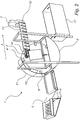
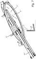
- FIG. 1 A first embodiment of the device 1 will now be discussed in detail with reference to Fig. 1 .
- the device 1 in Fig. 1a has a first receiving area 2 into which the containers are collected after entering the device.
- the device 1 comprises a rotatable transporting device 4 provided with an elevating member 5 for transporting containers from the first receiving area 2 to a second receiving area 3.
- the elevating member 5 moves along and is locked to a circumferential path around a first axis x upon activation of the transporting device 4, which first axis x is inclined at an angle of 0 to 45° relative the horizontal plane.
- the elevating member 5 randomly brings the containers, one by one, from the first receiving area 2 to the second receiving area 3.
- the container is elevated by the elevating member 5 from the first receiving area 2 by a scooping, pushing or nudging action.
- the container When the container is at a predetermined vertical position, the so-called drop-off point, it leaves the elevating member 5 of the transporting device 4 and falls by means of gravity, alternatively slides off by a sliding motion, to the second receiving area 3.
- the transport of the containers from the first receiving area 2 to the second receiving area 3 takes place mainly in the vertical plane.
- the container may then be forwarded to an inspection area 19 provided with inspection means 7 for identification of the container, see Fig. 1 .
- the container may be forwarded for further inspection, counting, recording, evaluating, sorting, storing, recycling, be returned to the user, or be returned to the first receiving area 2.
- the transporting device 4 may be designed in different ways, for example it may comprise a substantially circular plate 9 as illustrated in Fig. 1 . Such a plate may be solid or be provided with openings or apertures.
- the transporting device 4 may be a circular frame with a central opening.
- the transporting device may be a conveyor belt to which the elevating member 5 is fixedly attached (not shown).
- the transporting device 4 may be a wheel with a hub to which a number of spokes, each of which is provided with elevating members at its outer periphery (not shown).
- the transporting device 4 may comprise 1-20, 1-15, 2-25 or 5-10 elevating members 5.
- the number of the elevating members 5 may depend on the size of the transporting device 4.
- the elevating members 5 may be equally spaced or non-equally spaced around the transporting device 4.
- the elevating member 5 may have a size and design adapted for bringing containers of different shapes and sizes collected in the first receiving area 2 to the second receiving area 3.
- the elevating member 5 may extend radially from the outer periphery of the transporting device 4 towards the center of the transporting device.
- the elevating member 5 may be arranged such that at least a portion thereof extends radially outwards from the outer periphery of the transporting device 4, as shown in Figure 3a .
- the transporting device 4 comprises more than one elevating member 5, the size of the elevating members may, but need not, be the same.
- the sizes of the elevating members may be different such that different elevating members 5 are adapted for different types or sizes of containers.
- the distance between the elevating members 5 may be adapted to the diameter of the transporting device and hence to the application of the device 1.
- the number of the elevating members may be eight and the diameter of the transporting device may be 1000 mm. Furthermore, the elevating members may extend radially inwards to the center of the transporting device by 100 mm and axially by 150 mm.
- the elevating member 5 and/or the container supporting surface of the elevating member may for example be rectangular, elliptical, flat, cup-shaped, formed as a paddle or shovel etc., or be a combination of these such as flat and rectangular. It may be solid or have small openings.
- the transporting device 4 comprises more than one elevating member 5, the shape of the elevating members may, but need not, be the same.
- each elevating member 5 may, but need not, be provided with a rim arranged at the outer periphery of the elevating member, and extending in the transport direction, for providing additional support to the container upon transport of the container from the first receiving area 2 to the second receiving area 3.
- Each elevating member 5 may additionally or alternatively be provided with a rim extending in a direction substantially orthogonal to the first axis.
- the transporting device 4 may be arranged such that it is substantially parallel with a main transportation direction A of a container moving in the second receiving area 3.
- the transporting device 4 may further be arranged substantially vertically such that the first axis x around which upon the transporting device is rotating may be inclined with respect to the horizontal plane.
- the inclination of the first axis is about 15-20 ° with respect to the horizontal plane.
- the inclination of the first axis x and hence the transporting device 4 may make it easier for the elevating means 5 to single out a container from the first receiving area 2.
- the inclination of the first axis x and hence the transporting device may also prevent the containers from falling off the transporting device 4 upon activation, i.e. rotation, of the transporting device before the container reaches the drop-off point.
- the transporting device 4 may be rotatable in the clockwise or anti-clockwise direction.
- the transporting device 4 may be activated by a motor. Additionally or alternatively, the transporting device 4 may be activated by a driving wheel (not shown) arranged such that it is in contact with the transporting device 4. Upon activation of such driving wheel, by e.g. a motor, the transporting device may be activated.
- the motor may be controlled by a control unit.
- the transporting device 4 may be made of metal, plastic, wood or a combination thereof.
- the transporting device 4 may further comprise a retaining means 6.
- the purpose of the retaining means 6 is to retain the containers in the transporting device 4 when bringing the containers from the first receiving area 2 to the second receiving area 3.
- the retaining means 6 may be a peripheral barrier.
- the retaining means 6 may be arranged at and extend along the outer periphery of the transporting device 4 from the first receiving area to the drop off point.
- the retaining means may also have a shorter extension, and extend only along a portion of the peripheral distance between from the first receiving area to the drop off point. Additionally or alternatively, the retaining means extends also beyond the drop off point.
- the retaining means 6 may be connected to an external frame and, hence, not being attached to the transporting device 4.
- the retaining means 6 may be fixedly connected to the transporting device 4.
- the retaining means 6 may e.g. be a rim made e.g. plastics, metal or wood.
- the containers received in bulk are collected in the first receiving area 2 after entering the device 1.
- the containers are then kept in the first receiving area 2 until they are randomly brought from the first receiving area 2 to the second receiving area 3 by the elevating member 5.
- the lower part of the first receiving area 2 may be arranged substantially horizontal and at a lower part of the transporting device 4.
- the size and shape of the first receiving area 2 may be adapted for receiving containers of different sizes and shapes in bulk.
- the first receiving area 2 may be formed as a receptacle.
- the first receiving area may be bowl-shaped.
- the bottom of the first receiving area 2 may be curved having the same or a similar curvature as the periphery of the transporting device 4.
- the first receiving area 2 may be adapted such that the elevating member 5 travelling through the first receiving area 2 may be able to bring containers from the first receiving area.
- a lower vertical portion of the transporting device 4 may form an inner wall of the first receiving area 2.
- the first receiving area 2 may be made of e.g. metal and/or plastic.
- the device 1 comprises a second receiving area 3 for receiving the containers brought by the elevating members 5 arranged at the transporting device 4 from the first receiving area 2.
- the second receiving area 3 may be arranged adjacent to the transporting device 4 and at a higher vertical level with respect to the first receiving area 2.
- the second receiving area 3 may be positioned substantially horizontally in the center of the transporting device, but may also be arranged at a lower or higher position.
- the second receiving area 3 is a plate which is tilted outwards with respect to the transporting device 4.
- the tilt of the plate may enable the forwarding towards the container inspection area.
- the second receiving area 3 may have an elongated shape in the horizontal direction.
- the second receiving area 3 may have recesses at one or both ends adapted such that the elevating member 5 arranged on the transporting device 4 can pass upon activation of the transporting device 4.
- the second receiving area 3, being a plate, may be made of a material of low surface friction such as stainless steel, aluminum or a suitable plastic material.
- the conveyor belt of the third receiving area may be a V conveyor or a flat conveyor.
- the second receiving area 3 and the third receiving area 14 may be one and the same.
- Such arrangement may comprise solely of a conveyor belt onto which the containers fall and are transported to the container inspection area 19 (not shown).
- the arrangement may comprise solely of a plate made of a material with low surface friction, such as metal or a suitable plastic material, which is tilted towards the inspection area 19 such that the containers received at the combined second and third receiving area slides towards the inspection area 19.
- the device 1 may further comprise an inspection area 19 provided with inspection means 7 through which the containers are transported in order to identify the container. Based on the information obtained by the inspection means 7, the container may be either accepted or rejected. There are several different options how an accepted or rejected container can be handled.
- the container may be forwarded to a box (not shown), for example a box for containers to be recycled.
- a box for example a box for containers to be recycled.
- the container may be transported back to the first receiving area 2, back to the user, or directly to a trash collector 12.
- the inspection means 7 may be a camera or a scanner, such as a bar code reader.
- the inspection means 7 may be an OneRing system which comprises a camera for identifying a large part of the container.
- the camera of the OneRing system may be able to handle 80 to 220 objects per minute.
- inspection means e.g. cameras, scanners etc.
- arranged in series or in parallel in order to obtain different information of the containers such that the containers can be sorted based on this information.
- the inspection area 19 may further be provided with a decision unit arranged for receiving a signal from the inspection means 7 and based on this signal being arranged to send a container to a sorting station, back to the first receiving area 2 or to an outfeed 21 of the device 1.
- a container may be rejected if the inspection means 7 is not able to identify the container. If being rejected, the container may be sent back to the first receiving area 2 in order to provide for another read of the container. This may be done by a conveyor belt (not shown) positioned on a lowering mechanism and being arranged after the inspection area 19 with respect to the transport direction A of a container in the second receiving area 3 and/or third receiving area 14. Such a conveyor may be folded down and thereby forwarding the container back to the first receiving area 2.
- a rejected container may be returned back, via an outfeed 21 to the user, such that the user can determine whether he or she should insert the container in the device once again, throw away or keep the container. This may be done by a conveyor belt.
- the first receiving area 2 may be mounted onto brackets which may be mounted onto or in connection with a trash collector 12, see Fig. 1 .
- a trash collector may hence be situated below the first receiving area 2.
- the trash collector may have any shape, e.g. rectangular shape.
- the trash collector may be releasable connected to the device such that it can be released and the trash collector can be emptied.
- the first receiving area may further be provided with a lowering mechanism in connection with the brackets, a so-called drop-down chute 13.
- the first receiving area 2 may be emptied by means of lowering the drop-down chute 13 such that the containers in the first receiving area 2 fall into the trash collector 12. This may be useful when many containers have been returned to the first receiving area 2.
- the first receiving area 2 may be emptied after a certain time of activation of the transporting device 4, or after a certain number of containers have been rejected and thus returned back to the first receiving area 2.
- the containers ending up in the trash collector 12 may be taken care of and sorted manually or just being regarded as garbage.
- the device 1 may further comprise an infeed 8 for facilitating the containers to enter the first receiving area 2.
- the infeed 8 may be connected to the first receiving area 2.
- the size of the opening may be adapted to allow containers of different sizes and shapes to enter into the device 1 and to fulfill the requirements of the safety standard NS-EN 349:1992+A1:2008.
- the distance between the opening and the transporting device 4 may be adapted to fulfill the requirement of the standard, ISO 13857:2008, Safety of machines.
- the opening should comprise different safety arrangement for preventing injuries.
- it can comprise a light curtain with a light beam which functions such that, when the device 1 is running, the device is immediately shut down when the light beam is broken.
- the infeed 8 may comprise a tray which may be slightly tilted with respect to the horizontal plane in order to facilitate the containers to be forwarded to the first receiving area 2.
- the infeed may be made of a plastic material, metal and/or wood.
- the infeed 8 may further comprise rims on both sides in order to retain the containers being forwarded towards the first receiving area 2 and to prevent the containers from falling off the infeed upon being forwarded to the first receiving area 2.
- the tray may be provided with slits in order to handle loose objects, e.g. pieces of paper such as labels from containers, into which the loose objects can fall.
- loose objects e.g. pieces of paper such as labels from containers
- Loose objects may fall onto a steep surface located below the infeed and be guided directly or via a funnel 11 to a trash collector.
- the trash collector may, but need not, be the same as the trash collector 12 or containers discussed above.
- the infeed 8 may further comprise a conveyor belt in order to further facilitate transport of the containers from the tray towards the first receiving area 2.
- the conveyer belt may be arranged between the tray and the first receiving area of the device 1 and hence being adapted to the size of the infeed and the opening of the device.
- Such a conveyor belt may comprise rims on both sides in the longitudinal direction in order to prevent the objects from falling off from the conveyor and to retain the containers towards the first receiving area 2.
- the conveyor belt may be positioned substantially horizontal with respect to the horizontal plane.
- the infeed 8 may comprise solely a tray or solely a conveyor belt.
- a second embodiment of the device 1' which is similar to the embodiment of the device 1 described above will now be discussed with reference to Fig. 2 .
- the device 1' of the second embodiment differs from the device 1 of the first embodiment in that it is provided with additional retaining means 10' and in that the second receiving area 3' is arranged differently.
- additional retaining means 10' may optionally be arranged radially inside the transporting device 4' and is arranged radially below the elevating means 5'.
- the retaining means 10' may be curved and extend at least along a portion of the peripheral distance along which the container is brought between the first receiving area 2' and the second receiving area 3'.
- the purpose of the retaining means 10' is to prevent the containers from falling off the transporting device 4' before reaching the drop-off point when being brought from the first receiving area 2' to the second receiving area 3'.
- the retaining means 10' may be arranged on an external frame.
- the second receiving area 3' may be located at a higher vertical level as compared to the second receiving area of the device in the embodiment described with reference to Fig. 1 above.
- the containers may be forwarded from the elevating member 5' to the second receiving area 3' by means of gravity as discussed above.
- they may slide off the elevating member 5' by a sliding motion when the elevating member 5' has brought a container to a predetermined vertical position, i.e. the so-called drop-off point.
- How the container is released from or leaves the elevating member 5' may depend on the distance between the so-called drop-off point and the second receiving area 3'.
- the second receiving area 3' may be arranged at a higher part in the vertical plane of the transporting device 4' as compared to the arrangement shown in Fig. 1 . Further, as shown in Fig. 2 the second receiving area 3' may extend outwards from the transporting device 4' in the horizontal plane.
- the second receiving area 3' and/or the third receiving area 14' may further be provided with a retaining member 18' for retaining the containers upon being forwarded towards the inspection area 19'.
- the retaining member 18' may extend along the whole or a portion of the second receiving area 3' and/or third receiving area 14'.
- the retaining member 18' may be present on one or both sides of the second receiving area 3' and/or third receiving area 14'.
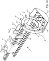
- a third embodiment of the device 1" will now be discussed with reference to Fig. 3a and Fig. 3b .
- the device 1" of the third embodiment differs from the device 1 in Fig. 1 mainly in how the transporting device 4" is arranged in relation to the rest of the components of the device 1".
- the transporting device 4" may be arranged such that the first axis x of the transporting device 4" is substantially parallel with respect to a main transportation direction A of a container in the second receiving area 3" and/or third receiving area 14'.
- the transporting device 4" may be provided as a frame 9" with a central opening. Alternatively, it may be a solid plate as discussed above.
- the transporting device 4" is provided as a frame 9", as shown in Fig. 3a and Fig. 3b , the transporting device 1" may be activated by a driving wheel (not shown) as described above.
- the elevating member 5" may be arranged such that at least a portion thereof extends radially outwards from the outer periphery of the transporting device 4".
- the elevating member may be arranged as described above, i.e. that it extends radially inwards towards the center of the transporting device 4".
- the device 1" may have additional retaining means 10" for retaining a container being brought from the first receiving area 2" to the second receiving area 3".
- the retaining means 10" may be arranged radially inside the transporting device 4".
- the retaining means may be connected to an external frame of the device 1".
- the retaining means 10" may extend at least along a portion of the path along which the container is brought between the first receiving area 2" and the second receiving area 3".
- the device 1" may have a rotating plate or surface 20" arranged at the top of the transporting device 4" guiding a container to change travel direction of the container, forcing the container to leave the transporting device 4" and enter the second receiving area 3".
- Such a rotating plate may be arranged on the retaining means 10".
- the device 1" may be provided with further retaining means 18" extending along the second receiving area 3" and/or the third receiving area 14" in order to retain the containers and to prevent them from falling off the second receiving area 3" and/or third receiving area 14".
- the container After being identified the container may be sorted by means of a propeller wheel 17".
- the propeller wheel 17" may for example be arranged at or in near vicinity of the inspection means 7".
- the arrangement of a propeller wheel for sorting of containers may be used also in the first and second embodiments of the device as discussed above.
- the propeller wheel 17" may be rotatable clockwise or anti-clockwise. Hence, depending on the propelling direction the propeller wheel may forward a container either to a first conveyor belt 15" or to a second conveyor belt 16" arranged on either side of the device 1".
- the conveyor belts 15" 16" may be arranged at a lower position in the vertical plane as compared to the second receiving area 3" and/or third receiving area 14".
- the first conveyor belt 15" may extend such that it is arranged from the end of the inspection area 19" to the first receiving area 2", see Fig 3a .
- the transport direction of a container travelling on the conveyor belt 15" and conveyor belt 16" may be the opposite as compared to the transport direction A of a container travelling on the second receiving area 3" and/or the third receiving area 14".
- the conveyor belt 15" and conveyor belt 16" may be arranged through the center of the frame 9" of the transporting device 4" in the horizontal plane.
- the first conveyor belt 15" may be arranged such that a container forwarded to the first conveyor belt may be transported back to the first receiving area 2". This may be useful if e.g. the inspection means 7" do not get a proper reading of the container and, hence, is not able to identify the container.
- the second conveyor 16" belt may be arranged such that a container being forwarded to the second conveyor belt may be transported back through the transporting device 4" to the user of the device 1".
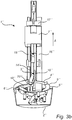
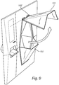
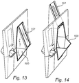
- a fourth embodiment of the device 1'" will now be discussed with reference to Figs. 4a - 7 .
- This embodiment is according to the invention.
- the device 1'" of the fourth embodiment differs from the device 1" in Figs. 3a and 3b mainly in how the second receiving area is arranged in relation to the transporting device 4'" and in how the retaining means (6"', 10"', 2001) are arranged.
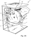
- the device 1'" in Fig. 4a has a first receiving area 2'" into which the containers are collected after entering the device 1'".
- the device 1'" comprises a rotatable transporting device 4'" provided with elevating members 5'" for transporting containers from the first receiving area 2'" to a second receiving area 3"'.
- the transporting device 4'" in Fig. 4a is provided as a rotatable plate 9"', similar to that of the previous embodiments but lacking the through-hole of the third embodiment.
- the elevating members 5'" are arranged such that at least a portion thereof extends radially outwards from the outer periphery of the transporting device 4"', just as in the third embodiment.
- the elevating members 5'" move along and are locked to a circumferential path around a first axis x upon activation of the transporting device 4"', which first axis x is inclined at an angle ⁇ 4 of approximately 20° relative the horizontal plane. This angle ⁇ 4 is shown in Fig. 5b .
- the elevating member 5'" randomly brings the containers, one by one, from the first receiving area 2'" to the second receiving area 3"'. This is shown in Fig. 4b .
- the container is elevated by the elevating member 5'" from the first receiving area 2'" by a scooping, pushing or nudging action.
- the container When the container is at a predetermined vertical position, the so-called drop-off point, it leaves the container supporting surface of the elevating member 5'" of the transporting device 4'" and slides off by a sliding motion to the second receiving area 3"', herein embodied by a conveyor belt 14"'. Hence, the transport of the containers from the first receiving area 2'" to the second receiving area 3'" takes place mainly in the vertical plane.
- the transporting device 4'" shown in Fig. 4a comprises 8 elevating members 5"'.
- the number of the elevating members 5'" depend on the size of the transporting device 4"'.
- the elevating members 5'" are equally spaced in the embodiment shown in Fig. 4a , and have a size and design adapted for bringing containers of different shapes and sizes collected in the first receiving area 2'" to the second receiving area 3"'.
- the elevating members 5'" may extend radially from the outer periphery of the transporting device 4'" and away from the center of the rotatable plate 9'" of the transporting device 4"'.
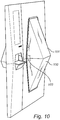
- Fig. 4b one bottle that has just been singulated or picked-up is in contact with a container supporting surface of a container elevating member 5"'. Another container which has not been picked up lies in the first receiving area 2"', waiting to be picked up by a container elevating member 5"'.
- the container elevating members 5'" are arranged at an angle ⁇ 1 relative to the rotatable plate 9"', wherein this angle ⁇ 1 is approximately 105°.
- the device 1'" has retaining means 6'" arranged radially outwards of a portion of the circumference of the circumferential path of the container elevating members 5"'.
- the retaining means 6'" is flexibly connected to the device 1'" such that it may deflect radially outwards when a container larger than the space between the retaining means 6'" and the container elevating members is moved from the first receiving area 2'" to the second receiving area 3"'. This is clearly shown in Fig. 4b . This allows the retaining means 6'" to exert a constant pressure on the containers transported on the container elevating members 5"', thus helping to keep them in place.
- the retaining means 6'" may be fixedly connected to the device 1'" in one end 2002.
- the retaining means 6'" is fixedly connected to the device 1'" at a location halfway between the second receiving area 3'" and the first receiving area 2"'.
- the retaining means 6'" extends from about 9 o'clock on the rotatable plate 9'" to approximately 11 or 12 o'clock.
- the retaining means 6'" can be seen as a leaf spring configured to exert pressure on the containers as they are transported from the first receiving area 2'" to the second receiving area 3"'.
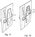
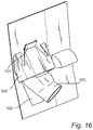
- the device 1'" further comprises secondary retaining means 2001, not shown in Fig. 4b , arranged for retaining a container on the container elevating members 5'" while the container is being brought from the first receiving area 2'" to the second receiving area 3"'.
- the secondary retaining means 2001 is more clearly shown in Fig. 6a .
- the secondary retaining means 2001 is a barrier that is substantially parallel with the transporting device 4"', i.e. a wall offset from the transporting device 4"'.
- the wall or secondary retaining means 2001 is seen in Fig. 6a as being arranged at a distance from the transporting device 4'" such that a container may fit between the rotatable plate 9'" of the transporting device 4'” and the secondary retaining means 2001.
- the secondary retaining means 2001 in combination with the rotatable plate 9'" and the other retaining means 6"', 10"', forms a channel or passage through which the containers may pass as they move from the first receiving area 2'" to the second receiving area 3"'.
- the transporting device 4'" is arranged such that the first axis x of the transporting device 4'" is arranged at an angle ⁇ 3 relative to a main transportation direction A of a container in the second receiving area 3"'.
- This angle is neither perpendicular, as in the first and second embodiment described above, nor parallel, as in the third embodiment described above. Instead, the first axis x is angled somewhere between, at an angle ⁇ 3 of around 105° relative to the main transporting direction A of the container in the second receiving area 3"'.
- the secondary retaining means 2001 is flexibly connected to the device 1'" by means of two flexible connection means, i.e. two leaf springs, such that the secondary retaining means 2001 may deflect in a direction that is substantially parallel with the first axis x.
- two flexible connection means i.e. two leaf springs
- the distance between the secondary retaining means 2001 and the rotatable plate 9'" of the transporting device 4'" may be increased by a container passing therebetween, thus causing the secondary retaining means 2001 to flexibly deflect outwards and away from the transporting device 4"'.
- the secondary retaining means 2001 comprises a guiding flange 2003.
- the guiding flange 2003 is a portion of the secondary retaining means 2001 that protrudes away from the transporting device 4'" at an angle ⁇ 5 relative to the remainder of the secondary retaining means 2001. This angle ⁇ 5 is approximately 135°, and this helps align containers that are slightly misaligned with the circumferential path of the container elevating members 5"'.
- the secondary retaining means 2001 extend from a position proximal to the drop-off point of the containers, to a position slightly less than halfway between the first receiving area and the drop-off point. In other words, the secondary retaining means 2001 extends from 12 o'clock on the rotatable plate 9'" to approximately 10 o'clock.
- the device 1'" also has tertiary retaining means 10'" for retaining a container being brought from the first receiving area 2'" to the second receiving area 3"'.
- the tertiary retaining means 10'" is arranged radially inwards of the circumferential path of the container elevating members 5"'.
- the tertiary retaining means 10'" comprises a container supporting surface proximal to an uppermost portion of the transporting device 4'" and which surface is facing radially outwards.
- containers elevated by the container elevating members 5'" may rest on a container supporting surface of the tertiary retaining means 10'" as they are transported from the first receiving area 2'" to the second receiving area 3"'.
- the tertiary retaining means 10'" is fixedly connected to the device 1'" by means of an arm extending in a direction substantially parallel with a horizontal projection of the first axis x.
- the tertiary retaining means 10'" extends along a portion of the circumferential path along which the container is brought between the first receiving area 2'" and the second receiving area 3"'. Specifically, the tertiary retaining means 10"' extends along approximately 20 % of the circumference of the rotatable plate 9"'. The extension of the tertiary retaining means 10'" is measured as a percentage of a 360° circle centered around the first axis x. One end of the tertiary retaining means 10'" is located at a position proximal to the container drop-off point, i.e. at a position proximal to 12 o'clock on the rotatable plate 9"'. In other words, the tertiary retaining means 10'” extends from an upper portion of the rotatable plate 9'" and down towards the first receiving area 2"'.
- the tertiary retaining means 10'" further comprises a wedge-shaped portion arranged to deflect containers from the container supporting surface of the elevating members 5'" if the containers are misaligned thereon.
- This wedge-shaped portion tapers off in a circumferential direction towards the first receiving area 2"'. In other words, the wedge-shaped portion points towards the first receiving area 2"'.
- the wedge-shaped portion of the tertiary retaining means 10'" tapers both in a radial direction and in an axial direction, thus ending in a point at a position at approximately 9 o'clock on the rotatable plate 9"'. As seen in Fig. 4b , the wedge-shaped portion tapers off at an angle ⁇ 2 of approximately 20°.
- the device 1' has a flange that is fixedly connected to the circumference of the rotatable plate 9'" and which flange extends towards the second receiving area 3"'.
- the second receiving area 3'" is located behind the rotatable plate 9"'.
- the flange extends from an outer periphery of the rotatable plate 9'" and backwards, beyond the back surface of the rotatable plate 9"'.
- the flange is arranged to guide a container as it moves from resting on the container elevating elements 5'" to sliding onto the second receiving area 3"'.
- the flange As the flange extends backwards from the rotatable plate 9"', it acts as a bridging surface between the container elevating members 5'" and the second receiving area 3"'. Thus, the risk of containers or other objects falling down behind the rotatable plate 9'" as the containers are transported from the container elevating members 5'" to the second receiving area 3'" is reduced.
- the flange is arranged at an angle ⁇ 6 relative to the rotatable plate 9"', wherein this angle ⁇ 5 is approximately 80°. Thus, the containers are caused to slide across the flange and down towards the second receiving area 3'" and the conveyor belt 13'" once the container elevating members 5'" reach a container drop-off point.
- the device 1'" further comprises a V-conveyor 14"', i.e. a conveyor belt.
- the second receiving area comprises one end of this conveyor belt 14"', the conveyor belt 14'" being arranged at an angle relative to a horizontal projection of the first axis x. This angle is approximately 105°.
- the conveyor belt 14'" extends from the second receiving area 3'" and backwards, away from the front of the device 1'" and the user.
- the conveyor belt 14'" is a V-conveyor, and comprises two belts. One belt, the one that is located closest to the rotatable plate 9"', is shorter than the other belt. This means that the conveyor belt 14'" may be arranged closer to the rotatable plate 9'" than what would have been possible if the two belts had been equally long. As the conveyor belt 14'" is arranged at an angle relative the rotatable plate 9"', having one band offset the other allows the conveyor belt 14'" to be arranged closer to the transporting device. Thus, the amount of non-active bridging surfaces between the rotatable plate 9'" and the second receiving area 3'" is reduced.
- the conveyor belt 14'" has a width that is approximately 65 - 70 mm, as measured in a direction that is perpendicular to a transporting direction of the conveyor belt 14'" and that is parallel with the horizontal plane. This enables misaligned containers to more easily fall off the conveyor belt 14'" on their own, without being forced to do so by means of e.g. a sorting device or sorting arrangement, Thus, a more efficient sorting of misaligned containers is achieved. Finally, the two belts of the conveyor belt 14'" are arranged at an angle relative to each other. This angle is approximately 50°.
- Said inspection area may comprise inspection means for identifying a container, as is described in relation to any of the previous embodiments.
- Said sorting station may comprise pneumatic sorting means, such that after being identified by the inspection means, arranged along the direction of travel of the conveyor belt 14"', the container may be sorted at a sorting station.
- This sorting station comprises a pneumatic sorter that is arranged after the inspection means, as seen in the direction of travel of the conveyor belt 14"'.
- the pneumatic sorter is arranged to push invalid containers off the conveyor belt 14'" by means of small bursts of gas.
- the sorting station may alternatively be of the type discussed in relation to the first, second or third embodiment.
- Figure 8 is a perspective view of a front of a reverse vending machine comprising a closing device according to one exemplary embodiment of a fifth concept, not according to the invention, wherein the closing device is in an open state.
- the fifth concept may be used with any type of bulk sorting reverse vending machine or vending machine comprising means for bulk sorting.
- the reverse vending machine 1 of Figs. 8 and 10 comprises:
- the movable closing device is arranged in the open state
- the movable closing device is arranged in the closed state.
- the movable closing device is arranged up stream of the in-feed, and is moved between the open and closed state by a translating non-rotational movement following the outside surface of the front.
- the direction of motion of the movable closing device is controlled by guides 102 attached to the front of the reverse vending machine; to which guides the movable closing device is attached.
- the size of the opening of the in-feed may be adapted to allow containers of different sizes and shapes to enter into the device 1 and to fulfill the requirements of the safety standard NS-EN 349:1992+A1:2008.
- the distance between the opening and the singulation transporting device may be adapted to fulfill the requirement of the standard, ISO 13857:2008, Safety of machines.
- the opening should comprise different safety arrangement for preventing injuries.
- it can comprise a light curtain with a light beam which functions such that, when the device 1 is running, the device is immediately shut down when the light beam is broken.
- the infeed may comprise a tray which may be slightly tilted with respect to the horizontal plane in order to facilitate the containers to be forwarded to the first receiving area.
- the infeed 100 may be made of a plastic material, metal and/or wood.
- the infeed 100 may further comprise rims on both sides in order to retain the containers being forwarded towards the first receiving area and to prevent the containers from falling off the infeed upon being forwarded to the first receiving area.
- the tray may be provided with slits in order to handle loose objects, e.g. pieces of paper such as labels from containers, into which the loose objects can fall.
- loose objects e.g. pieces of paper such as labels from containers
- Loose objects may fall onto a steep surface located below the infeed and be guided directly or via a funnel to a trash collector.
- the trash collector may, but need not, be the same as the trash collector or containers discussed above.
- the infeed may further comprise a conveyor belt in order to further facilitate transport of the containers from the tray towards the first receiving area.
- the conveyer belt may be arranged between the tray and the first receiving area of the device 1 and hence being adapted to the size of the infeed and the opening of the device.
- Such a conveyor belt may comprise rims on both sides in the longitudinal direction in order to prevent the objects from falling off from the conveyor and to retain the containers towards the first receiving area.
- the conveyor belt may be positioned substantially horizontal with respect to the horizontal plane.
- the infeed may comprise solely a tray or solely a conveyor belt.
- Figure 9 is a perspective view of a front of a reverse vending machine illustrating an alternative embodiment in the open state.
- This embodiment is equal to the one shown in Figure 8 and 10 , except that the movable closing device is attached to the front by means of hinges, to that the movable closing device may be rotated between an open and closed state.
- the position of the movable closing device is equal to the one illustrated in Figure 10 .
- Figure 12 is a perspective view of a front of a reverse vending machine illustrating an alternative embodiment in the open state.
- This embodiment is equal to the one shown in Figure 8 and 10 , except that the movable closing device is moved between the open and closed state by a translating non-rotational movement, which movement follows a direction transverse or orthogonal to the front surface of the machine as illustrated by the double arrows.
- Figure 11 shows this movable closing device in the closed state.
- Figure 14 is a perspective view of a front of a reverse vending machine illustrating an alternative embodiment in the open state.
- This embodiment is equal to the one shown in Figure 8 and 10 , except that the movable closing device is moved between the open and closed state by a translating non-rotational movement, which movement follows a direction transverse or to the front surface of the machine as illustrated by the double arrows.
- the direction of motion crosses the front surface of the machine at an angle between 5° and 80°, or between 10° and 60°.
- Figure 13 shows this movable closing device in the closed state.
- the movable closing device is arranged up stream of the infeed.
- Figure 15 is a perspective view of a front of a reverse vending machine illustrating an alternative embodiment in an intermediate state, i.e. in a state between the open state and the closed state.
- This embodiment is equal to the one shown in Figure 8 and 10 , except that the movable closing device is flat and arranged within the infeed of the device; i.e. it is arranged downstream of the opening of the infeed and up-stream of the end of the in-feed.
- the movable closing device is moved between the open and closed state by a translating non-rotational movement, which movement may follow a direction parallel to the front surface of the machine as illustrated by the double arrows.
- the movable closing device When the movable closing device is arranged in the closed state, it fully covers the passage formed by the infeed.
- Figure 16 is a perspective view of the front illustrated in Figures 13 and 14 , as seen from the back of the front.
- an optional funnel is provided, for guiding the containers towards the first receiving area.
- an optional back of the infeed 100' is shown.
- Figure 17 illustrates one exemplifying sequence of steps that may be used for controlling the in-feed of the reverse vending machine.
- the singulation process is started, 1010, or the movable closing device is closed and locked, 1020. That the singulation process is started before the closing of the movable closing device enables for the user to enter so many containers that a predetermined fill-level of the machine is reached and no more containers can or should be inserted (e.g. because the machine signals that to the user), await that some of the containers provided to the machine are processed so that the fill-level of the machine decreases, whereafter the user may add more containers into the machine.
- the movable closing device When the user has provided all his/her containers into the machine, 1011, the movable closing device is closed (manually or automatically), 1020, and automatically locked, 1021, so that the user may leave the machine while the machine continues to process the containers. Once the singulation process has been completed, 1012, the moveable closing device is unlocked.
- the movable closing device is closed and optionally locked, 1020 and 1021, before, or at the same time as, the singulation process starts,1010, this has the advantage that the user is protected from injuries caused by moving parts inside the machine, which parts are active at the singulation process; it also has the advantage of reducing noise caused by the singulation process during the whole singulation process.
- the in-feed is open in the idle state, i.e. when the machine is waiting for a new user.
- the in-feed is closed in the idle state.
- the step of receiving and keeping the bulk of used beverage or food containers at the first receiving area may further comprises the step of continuously single out individual containers from the bulk of containers in the first receiving area, and transporting the individual container from the first receiving area to a second receiving area which second receiving area is arranged at a higher vertical level.
- Figure 18 illustrates one example of how a signal may be directed in a reverse vending machine.
- a singulation monitoring device 2605 which may inform a control circuitry 2501 about e.g. the fill level of the machine or the first receiving area, the amount of objects received at the first receiving area, the rate at which containers or objects are received at the first receiving area, the position of the movable closing device, the amount of objects or containers present in the first receiving area and/or the container transportation rate from the first receiving area to the second receiving area.
- the control circuitry 2501 may issue a closing signal which is sent to the moveable closing device 2101, whereupon the movable closing device is closed automatically, i.e. non-manually.
- control circuitry may issue an opening signal which is sent to the moveable closing device, whereupon the movable closing device is opened automatically, i.e. non-manually. Additionally or alternatively, based on this information the control circuitry may issue an activation signal which is sent to the automatic locking device 103, whereupon the automatic locking device 103 locks the movable closing device in the closed state. Additionally or alternatively, the control circuitry may issue a deactivation signal which is sent to the automatic locking device 103, whereupon the automatic locking device 103 unlocks the movable closing device. Additionally or alternatively, the control circuitry may issue a signal to the first singulation transporting device when the movable closing device is open.
- the first transporting device may be prevented from starting the individual transporting of containers from the first receiving area to the second receiving area.
- the control circuitry may issue a signal to the first singulation transporting device if the movable closing device is opened. Thereby, the first singulation transporting device may be halted and the individual transporting of containers from the first receiving area to the second receiving area may be discontinued.
- the design of the transportation device including the container elevating members may be scaled or given different designs depending on e.g. the material, size, shape and weight of the containers that the singulation device is to be able to handle. Guided by this description and possibly in combination with some testing the person skilled in the art will be able to find a suitable design.
Landscapes
- Engineering & Computer Science (AREA)
- Mechanical Engineering (AREA)
- Physics & Mathematics (AREA)
- General Physics & Mathematics (AREA)
- Specific Conveyance Elements (AREA)
- Feeding Of Articles To Conveyors (AREA)
- Warehouses Or Storage Devices (AREA)
- Sorting Of Articles (AREA)
Priority Applications (2)
| Application Number | Priority Date | Filing Date | Title |
|---|---|---|---|
| PL17735157T PL3481753T3 (pl) | 2016-07-06 | 2017-07-06 | Urządzenie i sposób do rozdzielania zużytych pojemników po napojach albo żywności |
| EP20205441.7A EP3800620B1 (en) | 2016-07-06 | 2017-07-06 | Device and method for singulation of used beverage or food containers |
Applications Claiming Priority (4)
| Application Number | Priority Date | Filing Date | Title |
|---|---|---|---|
| EP16178096 | 2016-07-06 | ||
| EP16186310 | 2016-08-30 | ||
| EP16206226.9A EP3340192A1 (en) | 2016-12-22 | 2016-12-22 | Closable lid |
| PCT/EP2017/066936 WO2018007524A1 (en) | 2016-07-06 | 2017-07-06 | Device and method for singulation of used beverage or food containers |
Related Child Applications (1)
| Application Number | Title | Priority Date | Filing Date |
|---|---|---|---|
| EP20205441.7A Division EP3800620B1 (en) | 2016-07-06 | 2017-07-06 | Device and method for singulation of used beverage or food containers |
Publications (2)
| Publication Number | Publication Date |
|---|---|
| EP3481753A1 EP3481753A1 (en) | 2019-05-15 |
| EP3481753B1 true EP3481753B1 (en) | 2020-11-04 |
Family
ID=59276784
Family Applications (2)
| Application Number | Title | Priority Date | Filing Date |
|---|---|---|---|
| EP17735157.4A Active EP3481753B1 (en) | 2016-07-06 | 2017-07-06 | Device and method for singulation of used beverage or food containers |
| EP20205441.7A Active EP3800620B1 (en) | 2016-07-06 | 2017-07-06 | Device and method for singulation of used beverage or food containers |
Family Applications After (1)
| Application Number | Title | Priority Date | Filing Date |
|---|---|---|---|
| EP20205441.7A Active EP3800620B1 (en) | 2016-07-06 | 2017-07-06 | Device and method for singulation of used beverage or food containers |
Country Status (10)
| Country | Link |
|---|---|
| US (2) | US10549919B2 (pl) |
| EP (2) | EP3481753B1 (pl) |
| JP (2) | JP6774506B2 (pl) |
| CN (2) | CN111348388B (pl) |
| AU (1) | AU2017293129B2 (pl) |
| CA (1) | CA3028869C (pl) |
| DK (1) | DK3481753T3 (pl) |
| ES (1) | ES2858298T3 (pl) |
| PL (1) | PL3481753T3 (pl) |
| WO (1) | WO2018007524A1 (pl) |
Cited By (4)
| Publication number | Priority date | Publication date | Assignee | Title |
|---|---|---|---|---|
| DE102021131393A1 (de) | 2021-11-30 | 2023-06-01 | Trautwein Sb-Technik Gmbh | Rücknahmegerät und Rücknahmeverfahren für Leergut |
| WO2024165698A1 (en) | 2023-02-08 | 2024-08-15 | Tomra Systems Asa | A singulation arrangement for singulation of containers |
| EP4418225A1 (de) | 2023-02-16 | 2024-08-21 | Insensiv GmbH | Leergutbehälterrücknahmeautomat und vorrichtung für die sequenzielle einzelzuführung von leergutbehältern hierfür |
| EP4567759A1 (en) * | 2023-12-05 | 2025-06-11 | Tomra Systems ASA | Container return system having a bi-directional conveyor |
Families Citing this family (12)
| Publication number | Priority date | Publication date | Assignee | Title |
|---|---|---|---|---|
| US10549919B2 (en) * | 2016-07-06 | 2020-02-04 | Tomra Systems Asa | Device and method for singulation of used beverage or food containers |
| US10988324B2 (en) * | 2018-04-20 | 2021-04-27 | Greg Schombert | Food grade feeder device and system for rolls, sandwiches, odd shaped edibles and foodstuff |
| EP3866127A1 (en) | 2020-02-14 | 2021-08-18 | Tomra Systems ASA | Express mode processing |
| EP3886062A1 (en) | 2020-03-23 | 2021-09-29 | Tomra Systems ASA | Rvm (reverse vending machine) infeed indicator |
| KR102492893B1 (ko) * | 2020-08-25 | 2023-01-27 | 박병용 | 드럼형 식품 공급장치 |
| CN113387148A (zh) * | 2021-06-15 | 2021-09-14 | 郑智 | 一种废旧电池回收处理设备 |
| WO2023129626A1 (en) * | 2021-12-28 | 2023-07-06 | BioNex Solutions, Inc. | Automated in-place weighing of vials in tube racks |
| US20250242998A1 (en) * | 2022-04-05 | 2025-07-31 | Asofta Recycling Corporation Ltd. | Reverse vending system and method |
| IT202200007901A1 (it) * | 2022-04-21 | 2023-10-21 | Sic Srl | Macchina per la singolarizzazione di contenitori |
| CN114852584B (zh) * | 2022-05-16 | 2023-02-28 | 清华大学 | 氧化铝滚球机集尘和连续投取料设备及其使用方法和用途 |
| CN114906589B (zh) * | 2022-05-31 | 2023-10-03 | 天津中德应用技术大学 | 乘用车制动片生产线多角度可控换向装置 |
| CN120604277A (zh) | 2023-02-08 | 2025-09-05 | 陶朗系统公司 | 容器回收系统和方法 |
Family Cites Families (41)
| Publication number | Priority date | Publication date | Assignee | Title |
|---|---|---|---|---|
| DE1183433B (de) * | 1962-11-07 | 1964-12-10 | Beteiligungs & Patentverw Gmbh | Foerdergut-UEbergabestelle |
| US3338373A (en) * | 1966-11-28 | 1967-08-29 | Samuel S Aidlin | Automatic apparatus for orienting and feeding bottles, and the like |
| JPS488598Y1 (pl) * | 1968-10-22 | 1973-03-06 | ||
| JPS5551569B2 (pl) * | 1972-05-24 | 1980-12-25 | ||
| US3862536A (en) * | 1973-03-21 | 1975-01-28 | Gte Automatic Electric Lab Inc | High speed loading of reedblades |
| DE2517757C2 (de) * | 1975-04-22 | 1981-09-17 | Seitz-Werke Gmbh, 6550 Bad Kreuznach | Flaschenabtransporteur für Flaschenbehandlungsmaschinen in Längsbauweise |
| US4238023A (en) * | 1979-05-29 | 1980-12-09 | Promatic International Limited | Apparatus for orienting hollow, cap-like articles |
| US4345679A (en) * | 1980-05-09 | 1982-08-24 | Dewoolfson Bruce H | Container collection apparatus with electromagnetic sensor and method |
| US4492295A (en) * | 1982-03-05 | 1985-01-08 | Environmental Products Corporation | Automated redemption center for metal containers |
| US4653627A (en) * | 1985-08-26 | 1987-03-31 | Can And Bottle Systems, Inc. | Reverse vending machine |
| US4821920A (en) | 1987-08-28 | 1989-04-18 | Hoppmann Corporation | Method and apparatus for loading articles onto feeder by elevating ramp segments |
| DE3733510A1 (de) * | 1987-10-03 | 1989-04-13 | Schlafhorst & Co W | Vorrichtung zum transport von textilspulen |
| US4953682A (en) * | 1989-04-25 | 1990-09-04 | Salah Helbawi | Automatic reverse vending machine for aluminum can recycling |
| JPH03272902A (ja) * | 1990-03-22 | 1991-12-04 | Hitachi Ltd | 自動倉庫の安全装置 |
| US5090031A (en) * | 1990-10-09 | 1992-02-18 | Pyne Melvin L | Can counting machine |
| JPH05166039A (ja) * | 1991-12-12 | 1993-07-02 | Fuji Electric Co Ltd | 自動販売機のごみ回収装置 |
| JPH05266329A (ja) * | 1992-03-24 | 1993-10-15 | Sanyo Electric Co Ltd | 自動販売機の扉装置 |
| US5469783A (en) * | 1994-03-04 | 1995-11-28 | Eugene L. Fry | Collector for empty used recyclable beverage cans |
| US5918721A (en) * | 1995-12-20 | 1999-07-06 | Weinberger; William D. | Can collection apparatus |
| JP2824415B2 (ja) * | 1996-03-22 | 1998-11-11 | 河口湖精密株式会社 | 自動供給装置 |
| US6186308B1 (en) * | 1999-04-21 | 2001-02-13 | Can & Bottle Systems, Inc. | Reverse vending machine |
| JP2002037440A (ja) * | 2000-07-26 | 2002-02-06 | Hitachi Zosen Corp | ボトル整列装置 |
| NO319528B1 (no) * | 2000-08-04 | 2005-08-29 | Tomra Systems Asa | Sorteringsanordning |
| US6675947B2 (en) | 2001-03-30 | 2004-01-13 | Can & Bottle Systems, Inc. | Recycling machine with container compacting system |
| AU2002952885A0 (en) * | 2002-11-25 | 2002-12-12 | Turbocor Inc | High speed electric motor power supply |
| DE10335188A1 (de) * | 2003-07-30 | 2005-03-03 | Mrv Multi Reverse Vending Gmbh | Vereinzelungsvorrichtung |
| US7117987B2 (en) * | 2004-11-02 | 2006-10-10 | John R. Nalbach Engineering Co., Inc. | Article orientating apparatus |
| DK1947617T3 (en) * | 2005-01-25 | 2016-11-28 | Tomra Systems Asa | Polet system for installation in return slot |
| NO20050401D0 (no) * | 2005-01-25 | 2005-01-25 | Tomra Systems Asa | Kamera-assistert anordning for a betrakte et objekt |
| KR101067540B1 (ko) * | 2006-09-07 | 2011-09-27 | 큐릭, 인코포레이티드 | 음료를 생성하기 위한 방법 및 장치 |
| CA2697077C (en) * | 2007-08-22 | 2012-10-16 | Irm Llc | 2-heteroarylamino-pyrimidine derivatives as kinase inhibitors |
| US7565959B2 (en) * | 2007-09-18 | 2009-07-28 | John R. Nalbach Engineering Co, Inc. | Article orientating apparatus |
| US7635973B2 (en) * | 2007-11-16 | 2009-12-22 | Electro Scientific Industries, Inc. | Electronic component handler test plate |
| NO328793B1 (no) * | 2008-07-03 | 2010-05-18 | Tomra Systems Asa | Anordning ved returautomat |
| CN201285567Y (zh) * | 2008-08-16 | 2009-08-05 | 周钱超 | 自动回收饮料瓶装置 |
| DE102009017211B3 (de) | 2009-04-09 | 2010-11-18 | Envipco Holding N.V. | Vorrichtung zur Rücknahme von Leergut, insbesondere Kunststoffflaschen und Metalldosen |
| WO2011066839A1 (en) * | 2009-12-04 | 2011-06-09 | Anker Andersen A/S | Reverse vending system for batch registration of used beverage containers |
| DE102011002289A1 (de) * | 2011-04-27 | 2012-10-31 | Stefan Brenner | Vorrichtung zum Vereinzeln und/oder zum Sortieren von benutzten Getränkebehältern |
| ES2629498T3 (es) | 2013-02-08 | 2017-08-10 | Tomra Systems Asa | Dispositivo para separar y método correspondiente |
| US9181036B2 (en) * | 2013-02-27 | 2015-11-10 | Graham Packaging Company, L.P. | Automatic rotary transfer apparatus and method |
| US10549919B2 (en) | 2016-07-06 | 2020-02-04 | Tomra Systems Asa | Device and method for singulation of used beverage or food containers |
-
2017
- 2017-07-06 US US16/315,584 patent/US10549919B2/en active Active
- 2017-07-06 WO PCT/EP2017/066936 patent/WO2018007524A1/en not_active Ceased
- 2017-07-06 EP EP17735157.4A patent/EP3481753B1/en active Active
- 2017-07-06 CN CN202010249765.4A patent/CN111348388B/zh active Active
- 2017-07-06 AU AU2017293129A patent/AU2017293129B2/en active Active
- 2017-07-06 CA CA3028869A patent/CA3028869C/en active Active
- 2017-07-06 DK DK17735157.4T patent/DK3481753T3/da active
- 2017-07-06 JP JP2018565860A patent/JP6774506B2/ja active Active
- 2017-07-06 CN CN201780042008.6A patent/CN109415168B/zh active Active
- 2017-07-06 PL PL17735157T patent/PL3481753T3/pl unknown
- 2017-07-06 ES ES17735157T patent/ES2858298T3/es active Active
- 2017-07-06 EP EP20205441.7A patent/EP3800620B1/en active Active
-
2020
- 2020-01-03 US US16/733,636 patent/US11014758B2/en active Active
- 2020-10-02 JP JP2020167419A patent/JP7244471B2/ja active Active
Non-Patent Citations (1)
| Title |
|---|
| None * |
Cited By (6)
| Publication number | Priority date | Publication date | Assignee | Title |
|---|---|---|---|---|
| DE102021131393A1 (de) | 2021-11-30 | 2023-06-01 | Trautwein Sb-Technik Gmbh | Rücknahmegerät und Rücknahmeverfahren für Leergut |
| WO2023099362A1 (de) | 2021-11-30 | 2023-06-08 | Trautwein Sb-Technik Gmbh | Rücknahmegerät und rücknahmeverfahren für leergut |
| WO2024165698A1 (en) | 2023-02-08 | 2024-08-15 | Tomra Systems Asa | A singulation arrangement for singulation of containers |
| EP4418225A1 (de) | 2023-02-16 | 2024-08-21 | Insensiv GmbH | Leergutbehälterrücknahmeautomat und vorrichtung für die sequenzielle einzelzuführung von leergutbehältern hierfür |
| DE102023103873A1 (de) | 2023-02-16 | 2024-08-22 | insensiv GmbH | Leergutbehälterrücknahmeautomat und Vorrichtung für die sequenzielle Einzelzuführung von Leergutbehältern hierfür |
| EP4567759A1 (en) * | 2023-12-05 | 2025-06-11 | Tomra Systems ASA | Container return system having a bi-directional conveyor |
Also Published As
| Publication number | Publication date |
|---|---|
| CA3028869A1 (en) | 2018-01-11 |
| JP2019524592A (ja) | 2019-09-05 |
| CN109415168B (zh) | 2020-04-17 |
| CN111348388A (zh) | 2020-06-30 |
| ES2858298T3 (es) | 2021-09-30 |
| US20200216270A1 (en) | 2020-07-09 |
| JP6774506B2 (ja) | 2020-10-28 |
| US10549919B2 (en) | 2020-02-04 |
| CN111348388B (zh) | 2022-06-28 |
| CN109415168A (zh) | 2019-03-01 |
| EP3800620B1 (en) | 2026-03-25 |
| EP3800620A1 (en) | 2021-04-07 |
| DK3481753T3 (da) | 2021-02-01 |
| JP2021014366A (ja) | 2021-02-12 |
| US11014758B2 (en) | 2021-05-25 |
| AU2017293129B2 (en) | 2023-03-09 |
| WO2018007524A1 (en) | 2018-01-11 |
| JP7244471B2 (ja) | 2023-03-22 |
| US20190344969A1 (en) | 2019-11-14 |
| PL3481753T3 (pl) | 2021-07-19 |
| CA3028869C (en) | 2023-07-18 |
| AU2017293129A1 (en) | 2019-01-17 |
| EP3481753A1 (en) | 2019-05-15 |
Similar Documents
| Publication | Publication Date | Title |
|---|---|---|
| US11014758B2 (en) | Device and method for singulation of used beverage or food containers | |
| CN1020573C (zh) | 一种用于将容器自动定位和输入的装置 | |
| EP1281643B1 (en) | Automatic linear machine for orienting and aligning articles | |
| JP3226928B2 (ja) | 硬貨計数選別機 | |
| US4717026A (en) | Container scanning and accounting device | |
| JPH0780417A (ja) | 郵便物を分類するシステム及び方法と物品移送用受け | |
| US20130098812A1 (en) | Device for preparaing sealing elements | |
| CA2721141C (en) | An apparatus and method for feeding used objects | |
| EP3340192A1 (en) | Closable lid | |
| FI94380B (fi) | Laitteisto kiekkomaisten kappaleiden, etenkin kolikoiden erottelemiseksi | |
| JP2005239371A (ja) | 容器回収装置 | |
| US6915909B2 (en) | Device for receiving multi-format envelopes | |
| EP4662647A1 (en) | A container return system and method | |
| GB2173027A (en) | Coin-separating apparatus | |
| AU2010305151B2 (en) | Disk feeder for feeding used objects | |
| MXPA95002825A (en) | Insertion device and a method to transpose a current of products using the disposit |
Legal Events
| Date | Code | Title | Description |
|---|---|---|---|
| STAA | Information on the status of an ep patent application or granted ep patent |
Free format text: STATUS: UNKNOWN |
|
| STAA | Information on the status of an ep patent application or granted ep patent |
Free format text: STATUS: THE INTERNATIONAL PUBLICATION HAS BEEN MADE |
|
| PUAI | Public reference made under article 153(3) epc to a published international application that has entered the european phase |
Free format text: ORIGINAL CODE: 0009012 |
|
| STAA | Information on the status of an ep patent application or granted ep patent |
Free format text: STATUS: REQUEST FOR EXAMINATION WAS MADE |
|
| 17P | Request for examination filed |
Effective date: 20181220 |
|
| AK | Designated contracting states |
Kind code of ref document: A1 Designated state(s): AL AT BE BG CH CY CZ DE DK EE ES FI FR GB GR HR HU IE IS IT LI LT LU LV MC MK MT NL NO PL PT RO RS SE SI SK SM TR |
|
| AX | Request for extension of the european patent |
Extension state: BA ME |
|
| DAV | Request for validation of the european patent (deleted) | ||
| DAX | Request for extension of the european patent (deleted) | ||
| GRAP | Despatch of communication of intention to grant a patent |
Free format text: ORIGINAL CODE: EPIDOSNIGR1 |
|
| STAA | Information on the status of an ep patent application or granted ep patent |
Free format text: STATUS: GRANT OF PATENT IS INTENDED |
|
| INTG | Intention to grant announced |
Effective date: 20200519 |
|
| GRAS | Grant fee paid |
Free format text: ORIGINAL CODE: EPIDOSNIGR3 |
|
| GRAA | (expected) grant |
Free format text: ORIGINAL CODE: 0009210 |
|
| STAA | Information on the status of an ep patent application or granted ep patent |
Free format text: STATUS: THE PATENT HAS BEEN GRANTED |
|
| AK | Designated contracting states |
Kind code of ref document: B1 Designated state(s): AL AT BE BG CH CY CZ DE DK EE ES FI FR GB GR HR HU IE IS IT LI LT LU LV MC MK MT NL NO PL PT RO RS SE SI SK SM TR |
|
| REG | Reference to a national code |
Ref country code: GB Ref legal event code: FG4D |
|
| REG | Reference to a national code |
Ref country code: CH Ref legal event code: EP |
|
| REG | Reference to a national code |
Ref country code: AT Ref legal event code: REF Ref document number: 1330564 Country of ref document: AT Kind code of ref document: T Effective date: 20201115 |
|
| REG | Reference to a national code |
Ref country code: IE Ref legal event code: FG4D |
|
| REG | Reference to a national code |
Ref country code: DE Ref legal event code: R096 Ref document number: 602017026854 Country of ref document: DE |
|
| REG | Reference to a national code |
Ref country code: DK Ref legal event code: T3 Effective date: 20210126 |
|
| REG | Reference to a national code |
Ref country code: RO Ref legal event code: EPE |
|
| REG | Reference to a national code |
Ref country code: FI Ref legal event code: FGE |
|
| REG | Reference to a national code |
Ref country code: NO Ref legal event code: T2 Effective date: 20201104 |
|
| REG | Reference to a national code |
Ref country code: SE Ref legal event code: TRGR |
|
| REG | Reference to a national code |
Ref country code: PT Ref legal event code: SC4A Ref document number: 3481753 Country of ref document: PT Date of ref document: 20210302 Kind code of ref document: T Free format text: AVAILABILITY OF NATIONAL TRANSLATION Effective date: 20210224 |
|
| REG | Reference to a national code |
Ref country code: NL Ref legal event code: FP |
|
| REG | Reference to a national code |
Ref country code: GR Ref legal event code: EP Ref document number: 20210400272 Country of ref document: GR Effective date: 20210316 |
|
| REG | Reference to a national code |
Ref country code: SK Ref legal event code: T3 Ref document number: E 36598 Country of ref document: SK |
|
| PG25 | Lapsed in a contracting state [announced via postgrant information from national office to epo] |
Ref country code: RS Free format text: LAPSE BECAUSE OF FAILURE TO SUBMIT A TRANSLATION OF THE DESCRIPTION OR TO PAY THE FEE WITHIN THE PRESCRIBED TIME-LIMIT Effective date: 20201104 |
|
| PG25 | Lapsed in a contracting state [announced via postgrant information from national office to epo] |
Ref country code: BG Free format text: LAPSE BECAUSE OF FAILURE TO SUBMIT A TRANSLATION OF THE DESCRIPTION OR TO PAY THE FEE WITHIN THE PRESCRIBED TIME-LIMIT Effective date: 20210204 Ref country code: IS Free format text: LAPSE BECAUSE OF FAILURE TO SUBMIT A TRANSLATION OF THE DESCRIPTION OR TO PAY THE FEE WITHIN THE PRESCRIBED TIME-LIMIT Effective date: 20210304 |
|
| REG | Reference to a national code |
Ref country code: LT Ref legal event code: MG9D |
|
| PG25 | Lapsed in a contracting state [announced via postgrant information from national office to epo] |
Ref country code: HR Free format text: LAPSE BECAUSE OF FAILURE TO SUBMIT A TRANSLATION OF THE DESCRIPTION OR TO PAY THE FEE WITHIN THE PRESCRIBED TIME-LIMIT Effective date: 20201104 |
|
| PG25 | Lapsed in a contracting state [announced via postgrant information from national office to epo] |
Ref country code: LT Free format text: LAPSE BECAUSE OF FAILURE TO SUBMIT A TRANSLATION OF THE DESCRIPTION OR TO PAY THE FEE WITHIN THE PRESCRIBED TIME-LIMIT Effective date: 20201104 Ref country code: CZ Free format text: LAPSE BECAUSE OF FAILURE TO SUBMIT A TRANSLATION OF THE DESCRIPTION OR TO PAY THE FEE WITHIN THE PRESCRIBED TIME-LIMIT Effective date: 20201104 Ref country code: EE Free format text: LAPSE BECAUSE OF FAILURE TO SUBMIT A TRANSLATION OF THE DESCRIPTION OR TO PAY THE FEE WITHIN THE PRESCRIBED TIME-LIMIT Effective date: 20201104 Ref country code: SM Free format text: LAPSE BECAUSE OF FAILURE TO SUBMIT A TRANSLATION OF THE DESCRIPTION OR TO PAY THE FEE WITHIN THE PRESCRIBED TIME-LIMIT Effective date: 20201104 |
|
| REG | Reference to a national code |
Ref country code: DE Ref legal event code: R097 Ref document number: 602017026854 Country of ref document: DE |
|
| REG | Reference to a national code |
Ref country code: AT Ref legal event code: UEP Ref document number: 1330564 Country of ref document: AT Kind code of ref document: T Effective date: 20201104 |
|
| PLBE | No opposition filed within time limit |
Free format text: ORIGINAL CODE: 0009261 |
|
| STAA | Information on the status of an ep patent application or granted ep patent |
Free format text: STATUS: NO OPPOSITION FILED WITHIN TIME LIMIT |
|
| REG | Reference to a national code |
Ref country code: ES Ref legal event code: FG2A Ref document number: 2858298 Country of ref document: ES Kind code of ref document: T3 Effective date: 20210930 |
|
| 26N | No opposition filed |
Effective date: 20210805 |
|
| PG25 | Lapsed in a contracting state [announced via postgrant information from national office to epo] |
Ref country code: AL Free format text: LAPSE BECAUSE OF FAILURE TO SUBMIT A TRANSLATION OF THE DESCRIPTION OR TO PAY THE FEE WITHIN THE PRESCRIBED TIME-LIMIT Effective date: 20201104 Ref country code: IT Free format text: LAPSE BECAUSE OF FAILURE TO SUBMIT A TRANSLATION OF THE DESCRIPTION OR TO PAY THE FEE WITHIN THE PRESCRIBED TIME-LIMIT Effective date: 20201104 |
|
| PG25 | Lapsed in a contracting state [announced via postgrant information from national office to epo] |
Ref country code: SI Free format text: LAPSE BECAUSE OF FAILURE TO SUBMIT A TRANSLATION OF THE DESCRIPTION OR TO PAY THE FEE WITHIN THE PRESCRIBED TIME-LIMIT Effective date: 20201104 |
|
| REG | Reference to a national code |
Ref country code: CH Ref legal event code: PL |
|
| PG25 | Lapsed in a contracting state [announced via postgrant information from national office to epo] |
Ref country code: MC Free format text: LAPSE BECAUSE OF FAILURE TO SUBMIT A TRANSLATION OF THE DESCRIPTION OR TO PAY THE FEE WITHIN THE PRESCRIBED TIME-LIMIT Effective date: 20201104 |
|
| PG25 | Lapsed in a contracting state [announced via postgrant information from national office to epo] |
Ref country code: LI Free format text: LAPSE BECAUSE OF NON-PAYMENT OF DUE FEES Effective date: 20210731 Ref country code: CH Free format text: LAPSE BECAUSE OF NON-PAYMENT OF DUE FEES Effective date: 20210731 |
|
| PG25 | Lapsed in a contracting state [announced via postgrant information from national office to epo] |
Ref country code: IS Free format text: LAPSE BECAUSE OF FAILURE TO SUBMIT A TRANSLATION OF THE DESCRIPTION OR TO PAY THE FEE WITHIN THE PRESCRIBED TIME-LIMIT Effective date: 20210304 Ref country code: LU Free format text: LAPSE BECAUSE OF NON-PAYMENT OF DUE FEES Effective date: 20210706 |
|
| PG25 | Lapsed in a contracting state [announced via postgrant information from national office to epo] |
Ref country code: CY Free format text: LAPSE BECAUSE OF FAILURE TO SUBMIT A TRANSLATION OF THE DESCRIPTION OR TO PAY THE FEE WITHIN THE PRESCRIBED TIME-LIMIT Effective date: 20201104 |
|
| PG25 | Lapsed in a contracting state [announced via postgrant information from national office to epo] |
Ref country code: HU Free format text: LAPSE BECAUSE OF FAILURE TO SUBMIT A TRANSLATION OF THE DESCRIPTION OR TO PAY THE FEE WITHIN THE PRESCRIBED TIME-LIMIT; INVALID AB INITIO Effective date: 20170706 |
|
| PG25 | Lapsed in a contracting state [announced via postgrant information from national office to epo] |
Ref country code: MK Free format text: LAPSE BECAUSE OF FAILURE TO SUBMIT A TRANSLATION OF THE DESCRIPTION OR TO PAY THE FEE WITHIN THE PRESCRIBED TIME-LIMIT Effective date: 20201104 |
|
| PG25 | Lapsed in a contracting state [announced via postgrant information from national office to epo] |
Ref country code: MT Free format text: LAPSE BECAUSE OF FAILURE TO SUBMIT A TRANSLATION OF THE DESCRIPTION OR TO PAY THE FEE WITHIN THE PRESCRIBED TIME-LIMIT Effective date: 20201104 |
|
| PGFP | Annual fee paid to national office [announced via postgrant information from national office to epo] |
Ref country code: PL Payment date: 20250612 Year of fee payment: 9 |
|
| PGFP | Annual fee paid to national office [announced via postgrant information from national office to epo] |
Ref country code: GB Payment date: 20250605 Year of fee payment: 9 |
|
| PGFP | Annual fee paid to national office [announced via postgrant information from national office to epo] |
Ref country code: NL Payment date: 20250613 Year of fee payment: 9 Ref country code: BE Payment date: 20250619 Year of fee payment: 9 |
|
| PGFP | Annual fee paid to national office [announced via postgrant information from national office to epo] |
Ref country code: LV Payment date: 20250603 Year of fee payment: 9 Ref country code: PT Payment date: 20250623 Year of fee payment: 9 |
|
| PGFP | Annual fee paid to national office [announced via postgrant information from national office to epo] |
Ref country code: FR Payment date: 20250623 Year of fee payment: 9 |
|
| PGFP | Annual fee paid to national office [announced via postgrant information from national office to epo] |
Ref country code: GR Payment date: 20250618 Year of fee payment: 9 |
|
| PGFP | Annual fee paid to national office [announced via postgrant information from national office to epo] |
Ref country code: RO Payment date: 20250624 Year of fee payment: 9 |
|
| PGFP | Annual fee paid to national office [announced via postgrant information from national office to epo] |
Ref country code: SK Payment date: 20250612 Year of fee payment: 9 |
|
| PGFP | Annual fee paid to national office [announced via postgrant information from national office to epo] |
Ref country code: IE Payment date: 20250610 Year of fee payment: 9 |
|
| PGFP | Annual fee paid to national office [announced via postgrant information from national office to epo] |
Ref country code: SE Payment date: 20250610 Year of fee payment: 9 |
|
| PGFP | Annual fee paid to national office [announced via postgrant information from national office to epo] |
Ref country code: FI Payment date: 20250715 Year of fee payment: 9 Ref country code: ES Payment date: 20250805 Year of fee payment: 9 |
|
| PGFP | Annual fee paid to national office [announced via postgrant information from national office to epo] |
Ref country code: DK Payment date: 20250714 Year of fee payment: 9 Ref country code: DE Payment date: 20250604 Year of fee payment: 9 |
|
| PGFP | Annual fee paid to national office [announced via postgrant information from national office to epo] |
Ref country code: NO Payment date: 20250709 Year of fee payment: 9 |
|
| PGFP | Annual fee paid to national office [announced via postgrant information from national office to epo] |
Ref country code: TR Payment date: 20250702 Year of fee payment: 9 |
|
| PGFP | Annual fee paid to national office [announced via postgrant information from national office to epo] |
Ref country code: AT Payment date: 20250625 Year of fee payment: 9 |