EP3480901B1 - Schwingungsdämpfende vorrichtung für gleitringbürsten - Google Patents
Schwingungsdämpfende vorrichtung für gleitringbürsten Download PDFInfo
- Publication number
- EP3480901B1 EP3480901B1 EP17200075.4A EP17200075A EP3480901B1 EP 3480901 B1 EP3480901 B1 EP 3480901B1 EP 17200075 A EP17200075 A EP 17200075A EP 3480901 B1 EP3480901 B1 EP 3480901B1
- Authority
- EP
- European Patent Office
- Prior art keywords
- sliding brush
- sliding
- absorbing material
- slip
- housing
- Prior art date
- Legal status (The legal status is an assumption and is not a legal conclusion. Google has not performed a legal analysis and makes no representation as to the accuracy of the status listed.)
- Active
Links
Images


Classifications
-
- H—ELECTRICITY
- H01—ELECTRIC ELEMENTS
- H01R—ELECTRICALLY-CONDUCTIVE CONNECTIONS; STRUCTURAL ASSOCIATIONS OF A PLURALITY OF MUTUALLY-INSULATED ELECTRICAL CONNECTING ELEMENTS; COUPLING DEVICES; CURRENT COLLECTORS
- H01R39/00—Rotary current collectors, distributors or interrupters
- H01R39/02—Details for dynamo electric machines
- H01R39/46—Auxiliary means for improving current transfer, or for reducing or preventing sparking or arcing
-
- F—MECHANICAL ENGINEERING; LIGHTING; HEATING; WEAPONS; BLASTING
- F16—ENGINEERING ELEMENTS AND UNITS; GENERAL MEASURES FOR PRODUCING AND MAINTAINING EFFECTIVE FUNCTIONING OF MACHINES OR INSTALLATIONS; THERMAL INSULATION IN GENERAL
- F16F—SPRINGS; SHOCK-ABSORBERS; MEANS FOR DAMPING VIBRATION
- F16F15/00—Suppression of vibrations in systems; Means or arrangements for avoiding or reducing out-of-balance forces, e.g. due to motion
- F16F15/02—Suppression of vibrations of non-rotating, e.g. reciprocating systems; Suppression of vibrations of rotating systems by use of members not moving with the rotating systems
- F16F15/04—Suppression of vibrations of non-rotating, e.g. reciprocating systems; Suppression of vibrations of rotating systems by use of members not moving with the rotating systems using elastic means
- F16F15/08—Suppression of vibrations of non-rotating, e.g. reciprocating systems; Suppression of vibrations of rotating systems by use of members not moving with the rotating systems using elastic means with rubber springs ; with springs made of rubber and metal
-
- H—ELECTRICITY
- H01—ELECTRIC ELEMENTS
- H01R—ELECTRICALLY-CONDUCTIVE CONNECTIONS; STRUCTURAL ASSOCIATIONS OF A PLURALITY OF MUTUALLY-INSULATED ELECTRICAL CONNECTING ELEMENTS; COUPLING DEVICES; CURRENT COLLECTORS
- H01R39/00—Rotary current collectors, distributors or interrupters
- H01R39/02—Details for dynamo electric machines
- H01R39/022—Details for dynamo electric machines characterised by the materials used, e.g. ceramics
- H01R39/027—Insulating materials
-
- H—ELECTRICITY
- H01—ELECTRIC ELEMENTS
- H01R—ELECTRICALLY-CONDUCTIVE CONNECTIONS; STRUCTURAL ASSOCIATIONS OF A PLURALITY OF MUTUALLY-INSULATED ELECTRICAL CONNECTING ELEMENTS; COUPLING DEVICES; CURRENT COLLECTORS
- H01R39/00—Rotary current collectors, distributors or interrupters
- H01R39/02—Details for dynamo electric machines
- H01R39/08—Slip-rings
-
- H—ELECTRICITY
- H01—ELECTRIC ELEMENTS
- H01R—ELECTRICALLY-CONDUCTIVE CONNECTIONS; STRUCTURAL ASSOCIATIONS OF A PLURALITY OF MUTUALLY-INSULATED ELECTRICAL CONNECTING ELEMENTS; COUPLING DEVICES; CURRENT COLLECTORS
- H01R39/00—Rotary current collectors, distributors or interrupters
- H01R39/02—Details for dynamo electric machines
- H01R39/18—Contacts for co-operation with commutator or slip-ring, e.g. contact brush
- H01R39/24—Laminated contacts; Wire contacts, e.g. metallic brush, carbon fibres
Definitions
- the invention relates to Slip-rings and brushes for Slip-Rings for transmission of electrical signals between rotating parts. Specifically, it relates to a vibration absorbing and stabilizing device for gold wire brushes.
- slip rings are used to transfer electrical power and/or signals between a rotating and a stationary part. Such slip rings are used in different applications, like wind energy plants or computer tomography scanners. There are also many military and aerospace applications in which slip rings are used.
- Slip rings are generally based on a first part having sliding tracks and a second part having brushes for sliding on the sliding tracks by a rotational movement. Due to external interference or by changes in friction, interfering movements of the brush other than the rotational movement or oscillations of the brush may occur. Specifically, if the excitation mechanism is based on friction effects, the term frictional induced vibration for these interfering movements is used. Such interfering movements may cause contact noise and/or contact interruptions, adversely affecting signal quality. In applications with an inductive load, electrical arcing may occur during such interruptions, which leads to significant corrosion and wear of the brush and the sliding track. As long as minimum arcing voltage and minimum arcing current e.g. 100 mA and 12 V for gold-gold contacts is exceeded also purely ohmic circuits will be subjected to arcing. At lower values still melting can occur with subsequent damage and wear.
- EP 066 27 36 A1 discloses a multi-fiber brush where a strand of multiple thin fibers is used for contacting a sliding track. Due to the internal friction between the individual fibers, oscillations are suppressed.
- the drawback is the complex design having multiple thin wires held by a ferrule, which is expensive and difficult to manufacture. Furthermore, the fiber bundle has a comparatively large diameter and therefore requires a broad sliding track.
- JP S598275U An electrical contact brush with an absorbing material is disclosed in JP S598275U .
- a sliding brush with absorbing material is disclosed in JP S56139373 .
- JP H0993877 discloses a sliding contact with an absorbing material.
- JP S50144202U discloses a slipring contact with an absorbing polymer material.
- JP H01132075 discloses a slipring assembly.
- the problem to be solved by the invention is to stabilize a sliding brush and preferably a wire brush for a slipring such that oscillations and/or interfering movements are reduced. This may further lead to a reduction of contact noise, an increase in signal quality, lifetime and reliability of the brush.
- the solution should be simple and inexpensive. Preferably it does not require a change in the design of existing brush blocks or slip rings.
- the solution should be usable for retrofitting existing brushes.
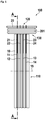
- a slip-ring assembly 100 comprises a slip-ring module 110 and a slip-ring brush block 120.
- the slip-ring module 110 may rotate about the rotation axis 15 and preferably comprises an insulating body 10, having a plurality of sliding tracks.
- four sliding tracks 11, 12, 13, and 14 are shown. It is obvious, that there may be any other number of sliding tracks.
- the sliding tracks are embedded and/or held by the insulating body. Preferably, the sliding tracks are insulated against each other. There may also be configurations, where at least some of the sliding tracks are connected together electrically. This may be useful for transferring higher currents or signals with a lower noise level.
- a preferred embodiment of sliding tracks having V-shaped grooves is shown. These V-grooves have the advantage that they can guide wires sliding on them and keep them precisely on a predetermined track. It is obvious that any other type of sliding track may be used instead, like tracks having multiple grooves or tracks without grooves, having a plane surface.
- the slip-ring brush block comprises a brush carrier 20 which may comprise a printed circuit board or any other insulating material. It may also comprise a conducting material like a metal, with insulated portions for holding the brushes.
- the brush block preferably holds a plurality of sliding brushes. In this embodiment, four wire brushes 21, 22, 23, 24 are shown. It is obvious, that there may be any other number of brushes and any other kind of brushes. For example, there may be multi-fiber brushes or carbon brushes.
- the brushes are spaced such that they fit to corresponding sliding tracks of the slip-ring module. There must not necessarily be one brush per sliding track. There may also be a plurality of brushes contacting a sliding track to increase current capability and/or reduce noise and/or contact resistance.
- a first absorbing device 201 is provided at the four wire brushes 21, 22, 23, 24 to reduce vibrations and/or oscillations.
- the first absorbing device 201 may only cover a smaller number of brushes, or there may be multiple absorbing devices, each device covering a smaller number of brushes.
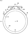
- FIG 2 a sectional view of the first embodiment is shown in a plane cut through lines A-A in figure 1 .
- the slip-ring module has a free bore, for example for carrying cables.
- a connector 16 is shown, which may be a soldering point or soldering pin or a connector, which contacts the first sliding track 11.
- a connecting cable may be soldered to this connector.
- the other sliding tracks also have connectors to contact the sliding tracks from the inner side of the insulating body.
- first sliding brush 21 and fifth sliding brush 25 contact first sliding track 11.
- a first absorbing device 201 and a second absorbing device 202 are shown.
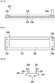
- details of a general sliding brush 30 are shown.
- the sliding brush 30 has a first end 31 by which it is preferably held by a brush carrier 20. Opposing thereto is a second end 32. Between the first end 31 and the second end 32 is a contact section 33. This contact section is designed for contacting the sliding track. Preferably, an absorbing device 201 is arranged between the first end and the contact section.
- figure 3 a detail of figure 2 is shown. Here, details of the absorbing devices can be better seen.
- Figure 4 shows a slightly modified embodiment of figure 3 .
- the absorbing devices 201, 202 are held by first fixation means 203 and second fixation means 204 to the brush carrier.
- FIG 5 a short side view of an absorbing device 200 is shown.
- the absorbing device has a housing 210 comprising a first housing part 211 and a second housing part 212. Details of the housing parts be shown in more detail later.
- Figure 6 shows a sectional view of figure 5 . This clearly shows the elastic absorbing material 220 between the housing parts.
- the fillet 239 is beneficial for larger housing parts as it increases stability.
- Figure 7 shows a top view of the housing.
- Figure 8 shows a side view of the housing.
- Figure 9 shows a sectional side view. This also shows, how two identical housing parts 211, 212 are connected together to form a housing.
- a second housing part may be placed upside down and rotated about 180 degrees on a first housing part.
- the elastic absorbing material 220 may comprise a first layer 221 and a second layer 222. There may also be any other number of layers.
- the absorbing material parts are dimensioned in such a way that they enclose the sliding brushes when the housing parts are connected mechanically to a housing.
- Figure 10 shows a sectional side view of a housing part 230. It has a base 231 with a groove 232 for the elastic absorbing material (not shown here) and a fillet 239 for increasing stability.
- cantilever snap arms 234, 235 at one side and a matching opening 233 at the other side are provided.
- Figure 11 shows a top view of a housing part.
- Figure 12 shows a front view of a housing part.
- a first cantilever snap arm 234 having a first projection 236 and a second cantilever snap arm 235 having a second projection 237 are shown.
Landscapes
- Engineering & Computer Science (AREA)
- Chemical & Material Sciences (AREA)
- General Engineering & Computer Science (AREA)
- Combustion & Propulsion (AREA)
- Physics & Mathematics (AREA)
- Acoustics & Sound (AREA)
- Aviation & Aerospace Engineering (AREA)
- Mechanical Engineering (AREA)
- Ceramic Engineering (AREA)
- Motor Or Generator Current Collectors (AREA)
Claims (12)
- Gleitbürstenanordnung (130) für einen Schleifring, umfassend mindestens eine Gleitbürste (21, 22, 23, 24, 30), wobei die mindestens eine Gleitbürste (21, 22, 23, 24, 30) ein erstes Ende (31) zum Halten der mindestens einen Gleitbürste (21, 22, 23, 24, 30), diesem gegenüberliegend ein zweites Ende (32) und ein Kontaktabschnitt (33) zwischen den Enden umfasst, wobei die mindestens eine Gleitbürste (21, 22, 23, 24, 30) ferner einen Metalldraht oder ein Metallblech umfasst, und
eine Absorptionsvorrichtung (201, 202) zum Reduzieren von Vibrationen und/oder Oszillationen an der mindestens einen Gleitbürste (21, 22, 23, 24, 30) angebracht ist,
dadurch gekennzeichnet, dass
die Absorptionsvorrichtung (201, 202) ein Gehäuse (210) umfasst, das ein elastisches Absorptionsmaterial (220) umschließt, und
mindestens ein Abschnitt der mindestens einen Gleitbürste (21, 22, 23, 24, 30) von dem Absorptionsmaterial (220) umschlossen ist und/oder das Absorptionsmaterial (220) von der mindestens einen Gleitbürste (21, 22, 23, 24, 30) durchdrungen ist. - Gleitbürstenanordnung (130) nach Anspruch 1,
dadurch gekennzeichnet, dass
dass das elastische Absorptionsmaterial (220) ein Polymer umfasst. - Gleitbürstenanordnung (130) nach einem der vorhergehenden Ansprüche,
dadurch gekennzeichnet, dass
das elastische Absorptionsmaterial (220) mindestens eines von einem Schaum, einem Elastomer und/oder einem Gel umfasst. - Gleitbürstenanordnung (130) nach einem der vorhergehenden Ansprüche,
dadurch gekennzeichnet, dass
die Absorptionsvorrichtung an mindestens einer Gleitbürste (21, 22, 23, 24, 30) zwischen dem ersten Ende (31) und dem Kontaktabschnitt (33) angebracht ist. - Gleitbürstenanordnung (130) nach einem der vorhergehenden Ansprüche,
dadurch gekennzeichnet, dass
das Gehäuse (210) ein elastisches Absorptionsmaterial (220, 221) umfasst, das vorzugsweise mindestens eines aus einem Schaum, einem Elastomer und einem Gel umfasst. - Gleitbürstenanordnung (130) nach einem der vorhergehenden Ansprüche,
dadurch gekennzeichnet, dass
das Gehäuse (210) zwei identische Gehäuseteile (211, 212) mit einer länglichen Basis (231) mit einem Schnapparm (234, 235) an einer Seite und an der gegenüberliegenden Seite eine Öffnung (233) umfasst, in welche Schnapparm (234, 235) passt. - Gleitbürstenanordnung (130) nach einem der vorhergehenden Ansprüche,
dadurch gekennzeichnet, dass
die längliche Basis (231) eine Nut (232) zum Halten des elastischen Absorptionsmaterials (220) hat. - Gleitbürstenanordnung (130) nach einem der vorhergehenden Ansprüche,
dadurch gekennzeichnet, dass
ein vorgefertigtes Gehäuseteil ein Blatt aus elastischem Absorptionsmaterial umfasst. - Gleitbürstenanordnung (130) nach dem vorhergehenden Anspruch,
dadurch gekennzeichnet, dass
das Blatt aus elastischem Absorptionsmaterial an das Gehäuseteil angeklebt oder angeformt ist. - Gleitbürstenanordnung (130) nach dem vorhergehenden Anspruch,
dadurch gekennzeichnet, dass
mindestens ein Gehäuseteil mindestens eine Leiste (239) aufweist, vorzugsweise in Längsrichtung. - Schleifringbürstenblock (120, 420) mit mindestens einer Gleitbürstenanordnung (130) nach einem der vorhergehenden Ansprüche.
- Schleifringanordnung (100) umfassend ein Schleifringmodul (110), weiterhin mindestens eine Schleifbahn (11, 12, 13, 14) und einen Schleifringbürstenblock (120, 420) nach dem vorhergehenden Anspruch umfassend.
Priority Applications (3)
| Application Number | Priority Date | Filing Date | Title |
|---|---|---|---|
| EP17200075.4A EP3480901B1 (de) | 2017-11-06 | 2017-11-06 | Schwingungsdämpfende vorrichtung für gleitringbürsten |
| US16/179,525 US10833467B2 (en) | 2017-11-06 | 2018-11-02 | Vibration absorbing device for slip-ring brushes |
| CN201811309707.5A CN109755832B (zh) | 2017-11-06 | 2018-11-06 | 用于滑环电刷的振动吸收装置 |
Applications Claiming Priority (1)
| Application Number | Priority Date | Filing Date | Title |
|---|---|---|---|
| EP17200075.4A EP3480901B1 (de) | 2017-11-06 | 2017-11-06 | Schwingungsdämpfende vorrichtung für gleitringbürsten |
Publications (2)
| Publication Number | Publication Date |
|---|---|
| EP3480901A1 EP3480901A1 (de) | 2019-05-08 |
| EP3480901B1 true EP3480901B1 (de) | 2020-02-19 |
Family
ID=60262815
Family Applications (1)
| Application Number | Title | Priority Date | Filing Date |
|---|---|---|---|
| EP17200075.4A Active EP3480901B1 (de) | 2017-11-06 | 2017-11-06 | Schwingungsdämpfende vorrichtung für gleitringbürsten |
Country Status (3)
| Country | Link |
|---|---|
| US (1) | US10833467B2 (de) |
| EP (1) | EP3480901B1 (de) |
| CN (1) | CN109755832B (de) |
Families Citing this family (2)
| Publication number | Priority date | Publication date | Assignee | Title |
|---|---|---|---|---|
| WO2021233540A1 (de) * | 2020-05-20 | 2021-11-25 | Schunk Transit Systems Gmbh | Ableitungseinrichtung |
| CN111817099B (zh) * | 2020-08-26 | 2022-02-01 | 徐洪杰 | 一种整体平板电刷式导电滑环 |
Family Cites Families (36)
| Publication number | Priority date | Publication date | Assignee | Title |
|---|---|---|---|---|
| US3049637A (en) * | 1959-10-30 | 1962-08-14 | Schunk & Ebe Gmbh | Brush holders for electrical machinery |
| NL7113387A (de) * | 1971-09-30 | 1973-04-03 | ||
| US3833404A (en) * | 1972-05-31 | 1974-09-03 | Research Corp | Vibration or sound damping coating for vibratory structures |
| CH571283A5 (de) * | 1974-04-17 | 1975-12-31 | Bbc Brown Boveri & Cie | |
| JPS5236321B2 (de) | 1974-05-10 | 1977-09-14 | ||
| JPS56785Y2 (de) * | 1974-05-15 | 1981-01-09 | ||
| IT1012948B (it) * | 1974-05-30 | 1977-03-10 | Montedison Spa | Derivati solfonici a struttura poliossapolifluoroalcanica e procedimento per la loro prepar zione |
| JPS5510112B2 (de) * | 1974-10-11 | 1980-03-13 | ||
| GB2013417B (en) * | 1978-01-30 | 1983-01-12 | Papst Motoren Kg | Electrical machine |
| FI800698A7 (fi) | 1980-03-07 | 1981-01-01 | Waertsilae Oy Ab | Riippulukko. |
| JPS56139373U (de) * | 1980-03-19 | 1981-10-21 | ||
| DE3142879A1 (de) * | 1981-10-29 | 1983-05-11 | Robert Bosch Gmbh, 7000 Stuttgart | Schleifkontakteinrichtung mit einer kohlebuerste |
| JPS598275U (ja) * | 1982-07-01 | 1984-01-19 | アルプス電気株式会社 | 直流モ−タのブラシ装置 |
| JPS598275A (ja) | 1982-07-02 | 1984-01-17 | Japan Storage Battery Co Ltd | 塩化チオニル・リチウム電池 |
| JPS6135135A (ja) * | 1984-07-26 | 1986-02-19 | Mabuchi Motor Co Ltd | 小型モ−タのブラシ防振装置 |
| JPH065974B2 (ja) * | 1985-04-19 | 1994-01-19 | 松下電器産業株式会社 | 小型モ−タの刷子制振材 |
| US20030155836A1 (en) * | 1985-07-31 | 2003-08-21 | Shigenori Uda | Small-size motor |
| JPH0753018B2 (ja) * | 1985-11-28 | 1995-06-05 | マブチモーター株式会社 | 小型モータのブラシ防振装置 |
| JPH01132075A (ja) * | 1987-11-17 | 1989-05-24 | Mitsubishi Electric Corp | 摺動接触装置 |
| JPH0440604A (ja) * | 1990-06-06 | 1992-02-12 | Pioneer Electron Corp | 電流伝達機構 |
| JPH05326095A (ja) * | 1992-05-15 | 1993-12-10 | Toshiba Corp | スリップリング装置 |
| JPH05342543A (ja) * | 1992-06-12 | 1993-12-24 | Sony Corp | 回転体の電気的接続のためのブラシの支持構造 |
| GB9319740D0 (en) * | 1993-09-24 | 1993-11-10 | Johnson Electric Sa | Brush gear for a miniature electric motor |
| FR2715005B1 (fr) | 1994-01-10 | 1996-03-22 | Air Precision Sa | Collecteur électrique tournant à balais multibrins. |
| US5777405A (en) * | 1994-10-05 | 1998-07-07 | Matsushita Electric Industrial Co., Ltd. | Damping member for minimotor and minimotor equipped with the same |
| JP3511752B2 (ja) * | 1995-09-27 | 2004-03-29 | アスモ株式会社 | モータブラシの支持構造 |
| JP2003527059A (ja) * | 2000-03-14 | 2003-09-09 | アーペーイー ポルトキャップ | 接触ブレード、ばね、および減衰要素を有するブラシを備えるブラシ・ホルダ |
| JP3519706B2 (ja) * | 2001-07-18 | 2004-04-19 | 東京パーツ工業株式会社 | ブラシ制振装置とこのブラシ制振装置の製造方法及びこのブラシ制振装置を備えた扁平型振動モータ |
| DE102009013084A1 (de) * | 2009-03-13 | 2010-06-10 | Siemens Aktiengesellschaft | Schleiffeder-Kontaktsystem |
| DE102011006820A1 (de) * | 2011-04-06 | 2012-10-11 | Schleifring Und Apparatebau Gmbh | Vibrationsfeste Schleifringanordnung |
| DE102011077358B3 (de) * | 2011-06-10 | 2012-12-06 | Schleifring Und Apparatebau Gmbh | Schwingungsunempfindlicher Bürstenblock für Schleifringe |
| DE102012203842B3 (de) * | 2012-03-12 | 2013-09-05 | Schleifring Und Apparatebau Gmbh | Schleifringbürste und Halter für Schleifringbürste |
| CN202651583U (zh) | 2012-05-29 | 2013-01-02 | 四川精通电气设备有限公司 | 一种防止摩擦产生绝缘附着物的导电滑环 |
| CN106797099B (zh) | 2014-10-14 | 2020-08-14 | 史莱福灵有限公司 | 带有磨损监测的滑环 |
| JP6425254B2 (ja) * | 2016-09-02 | 2018-11-21 | ミネベアミツミ株式会社 | モータ |
| JP6457987B2 (ja) * | 2016-09-02 | 2019-01-23 | ミネベアミツミ株式会社 | モータ、そのモータを備える回転装置及びその回転装置を備えた空調システムを備える車両 |
-
2017
- 2017-11-06 EP EP17200075.4A patent/EP3480901B1/de active Active
-
2018
- 2018-11-02 US US16/179,525 patent/US10833467B2/en active Active
- 2018-11-06 CN CN201811309707.5A patent/CN109755832B/zh active Active
Non-Patent Citations (1)
| Title |
|---|
| None * |
Also Published As
| Publication number | Publication date |
|---|---|
| US20190190221A1 (en) | 2019-06-20 |
| US10833467B2 (en) | 2020-11-10 |
| EP3480901A1 (de) | 2019-05-08 |
| CN109755832A (zh) | 2019-05-14 |
| CN109755832B (zh) | 2021-07-23 |
Similar Documents
| Publication | Publication Date | Title |
|---|---|---|
| CN102217151B (zh) | 滑动环单元 | |
| US10199778B2 (en) | High-speed connector inserts and cables | |
| US7719158B2 (en) | Slip-ring brush and slip-ring unit equipped with such a slip-ring brush | |
| US11658449B2 (en) | Slipring with wear monitoring | |
| JP6947874B2 (ja) | 導電スリップリング | |
| CN111200225B (zh) | 滑环机构 | |
| US9490600B2 (en) | High current slipring for multi fiber brushes | |
| CN110034443B (zh) | 一种hdmi电缆 | |
| US10424889B2 (en) | Stabilized gold wire brush for sliprings | |
| EP3480901B1 (de) | Schwingungsdämpfende vorrichtung für gleitringbürsten | |
| CN114945999B (zh) | 紧凑型集成旋转接头 | |
| US9093808B2 (en) | Vibration-resistant slip ring device | |
| US6994557B2 (en) | Electrical connector between two end points | |
| JP6574984B2 (ja) | 整流子モータ | |
| US20040154824A1 (en) | Contact assembly for a rotatable circuit element | |
| US12388222B2 (en) | Connector having vibration absorption and noise removal properties | |
| US6132240A (en) | Printed wiring board assembly for a connector with strain relief and terminal isolation | |
| CN102456453A (zh) | 一种面板安装用电位器 | |
| SU1501202A1 (ru) | Маломоментный проволочный токопровод | |
| JP2018021804A (ja) | 振動検出器 | |
| CN119340750A (zh) | 一种双层柱式滑环内层滑环导线防护装置及使用方法 | |
| SU1343488A1 (ru) | Маломоментный бесконтактный токоподвод | |
| CN114284720A (zh) | 一种双同轴电缆的馈电结构 | |
| US20070141903A1 (en) | Electrical connector assembly |
Legal Events
| Date | Code | Title | Description |
|---|---|---|---|
| STAA | Information on the status of an ep patent application or granted ep patent |
Free format text: STATUS: EXAMINATION IS IN PROGRESS |
|
| PUAI | Public reference made under article 153(3) epc to a published international application that has entered the european phase |
Free format text: ORIGINAL CODE: 0009012 |
|
| 17P | Request for examination filed |
Effective date: 20180502 |
|
| AK | Designated contracting states |
Kind code of ref document: A1 Designated state(s): AL AT BE BG CH CY CZ DE DK EE ES FI FR GB GR HR HU IE IS IT LI LT LU LV MC MK MT NL NO PL PT RO RS SE SI SK SM TR |
|
| AX | Request for extension of the european patent |
Extension state: BA ME |
|
| RBV | Designated contracting states (corrected) |
Designated state(s): AL AT BE BG CH CY CZ DE DK EE ES FI FR GB GR HR HU IE IS IT LI LT LU LV MC MK MT NL NO PL PT RO RS SE SI SK SM TR |
|
| GRAP | Despatch of communication of intention to grant a patent |
Free format text: ORIGINAL CODE: EPIDOSNIGR1 |
|
| STAA | Information on the status of an ep patent application or granted ep patent |
Free format text: STATUS: GRANT OF PATENT IS INTENDED |
|
| INTG | Intention to grant announced |
Effective date: 20190930 |
|
| GRAS | Grant fee paid |
Free format text: ORIGINAL CODE: EPIDOSNIGR3 |
|
| GRAA | (expected) grant |
Free format text: ORIGINAL CODE: 0009210 |
|
| STAA | Information on the status of an ep patent application or granted ep patent |
Free format text: STATUS: THE PATENT HAS BEEN GRANTED |
|
| AK | Designated contracting states |
Kind code of ref document: B1 Designated state(s): AL AT BE BG CH CY CZ DE DK EE ES FI FR GB GR HR HU IE IS IT LI LT LU LV MC MK MT NL NO PL PT RO RS SE SI SK SM TR |
|
| REG | Reference to a national code |
Ref country code: CH Ref legal event code: EP |
|
| REG | Reference to a national code |
Ref country code: DE Ref legal event code: R096 Ref document number: 602017011919 Country of ref document: DE |
|
| REG | Reference to a national code |
Ref country code: AT Ref legal event code: REF Ref document number: 1236025 Country of ref document: AT Kind code of ref document: T Effective date: 20200315 |
|
| REG | Reference to a national code |
Ref country code: IE Ref legal event code: FG4D |
|
| REG | Reference to a national code |
Ref country code: NL Ref legal event code: MP Effective date: 20200219 |
|
| PG25 | Lapsed in a contracting state [announced via postgrant information from national office to epo] |
Ref country code: FI Free format text: LAPSE BECAUSE OF FAILURE TO SUBMIT A TRANSLATION OF THE DESCRIPTION OR TO PAY THE FEE WITHIN THE PRESCRIBED TIME-LIMIT Effective date: 20200219 Ref country code: RS Free format text: LAPSE BECAUSE OF FAILURE TO SUBMIT A TRANSLATION OF THE DESCRIPTION OR TO PAY THE FEE WITHIN THE PRESCRIBED TIME-LIMIT Effective date: 20200219 Ref country code: NO Free format text: LAPSE BECAUSE OF FAILURE TO SUBMIT A TRANSLATION OF THE DESCRIPTION OR TO PAY THE FEE WITHIN THE PRESCRIBED TIME-LIMIT Effective date: 20200519 |
|
| REG | Reference to a national code |
Ref country code: LT Ref legal event code: MG4D |
|
| PG25 | Lapsed in a contracting state [announced via postgrant information from national office to epo] |
Ref country code: IS Free format text: LAPSE BECAUSE OF FAILURE TO SUBMIT A TRANSLATION OF THE DESCRIPTION OR TO PAY THE FEE WITHIN THE PRESCRIBED TIME-LIMIT Effective date: 20200619 Ref country code: GR Free format text: LAPSE BECAUSE OF FAILURE TO SUBMIT A TRANSLATION OF THE DESCRIPTION OR TO PAY THE FEE WITHIN THE PRESCRIBED TIME-LIMIT Effective date: 20200520 Ref country code: BG Free format text: LAPSE BECAUSE OF FAILURE TO SUBMIT A TRANSLATION OF THE DESCRIPTION OR TO PAY THE FEE WITHIN THE PRESCRIBED TIME-LIMIT Effective date: 20200519 Ref country code: LV Free format text: LAPSE BECAUSE OF FAILURE TO SUBMIT A TRANSLATION OF THE DESCRIPTION OR TO PAY THE FEE WITHIN THE PRESCRIBED TIME-LIMIT Effective date: 20200219 Ref country code: SE Free format text: LAPSE BECAUSE OF FAILURE TO SUBMIT A TRANSLATION OF THE DESCRIPTION OR TO PAY THE FEE WITHIN THE PRESCRIBED TIME-LIMIT Effective date: 20200219 Ref country code: HR Free format text: LAPSE BECAUSE OF FAILURE TO SUBMIT A TRANSLATION OF THE DESCRIPTION OR TO PAY THE FEE WITHIN THE PRESCRIBED TIME-LIMIT Effective date: 20200219 |
|
| PG25 | Lapsed in a contracting state [announced via postgrant information from national office to epo] |
Ref country code: NL Free format text: LAPSE BECAUSE OF FAILURE TO SUBMIT A TRANSLATION OF THE DESCRIPTION OR TO PAY THE FEE WITHIN THE PRESCRIBED TIME-LIMIT Effective date: 20200219 |
|
| PG25 | Lapsed in a contracting state [announced via postgrant information from national office to epo] |
Ref country code: DK Free format text: LAPSE BECAUSE OF FAILURE TO SUBMIT A TRANSLATION OF THE DESCRIPTION OR TO PAY THE FEE WITHIN THE PRESCRIBED TIME-LIMIT Effective date: 20200219 Ref country code: RO Free format text: LAPSE BECAUSE OF FAILURE TO SUBMIT A TRANSLATION OF THE DESCRIPTION OR TO PAY THE FEE WITHIN THE PRESCRIBED TIME-LIMIT Effective date: 20200219 Ref country code: SK Free format text: LAPSE BECAUSE OF FAILURE TO SUBMIT A TRANSLATION OF THE DESCRIPTION OR TO PAY THE FEE WITHIN THE PRESCRIBED TIME-LIMIT Effective date: 20200219 Ref country code: PT Free format text: LAPSE BECAUSE OF FAILURE TO SUBMIT A TRANSLATION OF THE DESCRIPTION OR TO PAY THE FEE WITHIN THE PRESCRIBED TIME-LIMIT Effective date: 20200712 Ref country code: SM Free format text: LAPSE BECAUSE OF FAILURE TO SUBMIT A TRANSLATION OF THE DESCRIPTION OR TO PAY THE FEE WITHIN THE PRESCRIBED TIME-LIMIT Effective date: 20200219 Ref country code: EE Free format text: LAPSE BECAUSE OF FAILURE TO SUBMIT A TRANSLATION OF THE DESCRIPTION OR TO PAY THE FEE WITHIN THE PRESCRIBED TIME-LIMIT Effective date: 20200219 Ref country code: LT Free format text: LAPSE BECAUSE OF FAILURE TO SUBMIT A TRANSLATION OF THE DESCRIPTION OR TO PAY THE FEE WITHIN THE PRESCRIBED TIME-LIMIT Effective date: 20200219 Ref country code: CZ Free format text: LAPSE BECAUSE OF FAILURE TO SUBMIT A TRANSLATION OF THE DESCRIPTION OR TO PAY THE FEE WITHIN THE PRESCRIBED TIME-LIMIT Effective date: 20200219 Ref country code: ES Free format text: LAPSE BECAUSE OF FAILURE TO SUBMIT A TRANSLATION OF THE DESCRIPTION OR TO PAY THE FEE WITHIN THE PRESCRIBED TIME-LIMIT Effective date: 20200219 |
|
| REG | Reference to a national code |
Ref country code: AT Ref legal event code: MK05 Ref document number: 1236025 Country of ref document: AT Kind code of ref document: T Effective date: 20200219 |
|
| REG | Reference to a national code |
Ref country code: DE Ref legal event code: R097 Ref document number: 602017011919 Country of ref document: DE |
|
| PLBE | No opposition filed within time limit |
Free format text: ORIGINAL CODE: 0009261 |
|
| STAA | Information on the status of an ep patent application or granted ep patent |
Free format text: STATUS: NO OPPOSITION FILED WITHIN TIME LIMIT |
|
| 26N | No opposition filed |
Effective date: 20201120 |
|
| PG25 | Lapsed in a contracting state [announced via postgrant information from national office to epo] |
Ref country code: IT Free format text: LAPSE BECAUSE OF FAILURE TO SUBMIT A TRANSLATION OF THE DESCRIPTION OR TO PAY THE FEE WITHIN THE PRESCRIBED TIME-LIMIT Effective date: 20200219 Ref country code: AT Free format text: LAPSE BECAUSE OF FAILURE TO SUBMIT A TRANSLATION OF THE DESCRIPTION OR TO PAY THE FEE WITHIN THE PRESCRIBED TIME-LIMIT Effective date: 20200219 |
|
| PG25 | Lapsed in a contracting state [announced via postgrant information from national office to epo] |
Ref country code: SI Free format text: LAPSE BECAUSE OF FAILURE TO SUBMIT A TRANSLATION OF THE DESCRIPTION OR TO PAY THE FEE WITHIN THE PRESCRIBED TIME-LIMIT Effective date: 20200219 Ref country code: PL Free format text: LAPSE BECAUSE OF FAILURE TO SUBMIT A TRANSLATION OF THE DESCRIPTION OR TO PAY THE FEE WITHIN THE PRESCRIBED TIME-LIMIT Effective date: 20200219 |
|
| PG25 | Lapsed in a contracting state [announced via postgrant information from national office to epo] |
Ref country code: MC Free format text: LAPSE BECAUSE OF FAILURE TO SUBMIT A TRANSLATION OF THE DESCRIPTION OR TO PAY THE FEE WITHIN THE PRESCRIBED TIME-LIMIT Effective date: 20200219 |
|
| REG | Reference to a national code |
Ref country code: CH Ref legal event code: PL |
|
| PG25 | Lapsed in a contracting state [announced via postgrant information from national office to epo] |
Ref country code: LU Free format text: LAPSE BECAUSE OF NON-PAYMENT OF DUE FEES Effective date: 20201106 |
|
| REG | Reference to a national code |
Ref country code: BE Ref legal event code: MM Effective date: 20201130 |
|
| PG25 | Lapsed in a contracting state [announced via postgrant information from national office to epo] |
Ref country code: LI Free format text: LAPSE BECAUSE OF NON-PAYMENT OF DUE FEES Effective date: 20201130 Ref country code: CH Free format text: LAPSE BECAUSE OF NON-PAYMENT OF DUE FEES Effective date: 20201130 |
|
| PG25 | Lapsed in a contracting state [announced via postgrant information from national office to epo] |
Ref country code: IE Free format text: LAPSE BECAUSE OF NON-PAYMENT OF DUE FEES Effective date: 20201106 |
|
| PG25 | Lapsed in a contracting state [announced via postgrant information from national office to epo] |
Ref country code: TR Free format text: LAPSE BECAUSE OF FAILURE TO SUBMIT A TRANSLATION OF THE DESCRIPTION OR TO PAY THE FEE WITHIN THE PRESCRIBED TIME-LIMIT Effective date: 20200219 Ref country code: MT Free format text: LAPSE BECAUSE OF FAILURE TO SUBMIT A TRANSLATION OF THE DESCRIPTION OR TO PAY THE FEE WITHIN THE PRESCRIBED TIME-LIMIT Effective date: 20200219 Ref country code: CY Free format text: LAPSE BECAUSE OF FAILURE TO SUBMIT A TRANSLATION OF THE DESCRIPTION OR TO PAY THE FEE WITHIN THE PRESCRIBED TIME-LIMIT Effective date: 20200219 |
|
| PG25 | Lapsed in a contracting state [announced via postgrant information from national office to epo] |
Ref country code: MK Free format text: LAPSE BECAUSE OF FAILURE TO SUBMIT A TRANSLATION OF THE DESCRIPTION OR TO PAY THE FEE WITHIN THE PRESCRIBED TIME-LIMIT Effective date: 20200219 Ref country code: AL Free format text: LAPSE BECAUSE OF FAILURE TO SUBMIT A TRANSLATION OF THE DESCRIPTION OR TO PAY THE FEE WITHIN THE PRESCRIBED TIME-LIMIT Effective date: 20200219 |
|
| PG25 | Lapsed in a contracting state [announced via postgrant information from national office to epo] |
Ref country code: BE Free format text: LAPSE BECAUSE OF NON-PAYMENT OF DUE FEES Effective date: 20201130 |
|
| PGFP | Annual fee paid to national office [announced via postgrant information from national office to epo] |
Ref country code: DE Payment date: 20251118 Year of fee payment: 9 |
|
| PGFP | Annual fee paid to national office [announced via postgrant information from national office to epo] |
Ref country code: GB Payment date: 20251120 Year of fee payment: 9 |
|
| PGFP | Annual fee paid to national office [announced via postgrant information from national office to epo] |
Ref country code: FR Payment date: 20251120 Year of fee payment: 9 |