EP3480901A1 - Schwingungsdämpfende vorrichtung für gleitringbürsten - Google Patents
Schwingungsdämpfende vorrichtung für gleitringbürsten Download PDFInfo
- Publication number
- EP3480901A1 EP3480901A1 EP17200075.4A EP17200075A EP3480901A1 EP 3480901 A1 EP3480901 A1 EP 3480901A1 EP 17200075 A EP17200075 A EP 17200075A EP 3480901 A1 EP3480901 A1 EP 3480901A1
- Authority
- EP
- European Patent Office
- Prior art keywords
- sliding brush
- sliding
- brush
- housing
- absorbing material
- Prior art date
- Legal status (The legal status is an assumption and is not a legal conclusion. Google has not performed a legal analysis and makes no representation as to the accuracy of the status listed.)
- Granted
Links
- 239000011358 absorbing material Substances 0.000 claims abstract description 30
- 229910052751 metal Inorganic materials 0.000 claims description 17
- 239000002184 metal Substances 0.000 claims description 17
- 229920001971 elastomer Polymers 0.000 claims description 3
- 239000000806 elastomer Substances 0.000 claims description 3
- 239000006260 foam Substances 0.000 claims description 3
- 238000000034 method Methods 0.000 claims description 2
- 229920000642 polymer Polymers 0.000 claims description 2
- 230000010355 oscillation Effects 0.000 description 6
- 239000000835 fiber Substances 0.000 description 5
- PXHVJJICTQNCMI-UHFFFAOYSA-N Nickel Chemical compound [Ni] PXHVJJICTQNCMI-UHFFFAOYSA-N 0.000 description 4
- 239000004020 conductor Substances 0.000 description 4
- PCHJSUWPFVWCPO-UHFFFAOYSA-N gold Chemical compound [Au] PCHJSUWPFVWCPO-UHFFFAOYSA-N 0.000 description 4
- 239000011810 insulating material Substances 0.000 description 4
- 230000002452 interceptive effect Effects 0.000 description 4
- 239000000463 material Substances 0.000 description 4
- 239000006096 absorbing agent Substances 0.000 description 3
- 239000003575 carbonaceous material Substances 0.000 description 3
- 229910052737 gold Inorganic materials 0.000 description 3
- 239000010931 gold Substances 0.000 description 3
- 229910052709 silver Inorganic materials 0.000 description 3
- 239000004332 silver Substances 0.000 description 3
- OKTJSMMVPCPJKN-UHFFFAOYSA-N Carbon Chemical compound [C] OKTJSMMVPCPJKN-UHFFFAOYSA-N 0.000 description 2
- KDLHZDBZIXYQEI-UHFFFAOYSA-N Palladium Chemical compound [Pd] KDLHZDBZIXYQEI-UHFFFAOYSA-N 0.000 description 2
- BQCADISMDOOEFD-UHFFFAOYSA-N Silver Chemical compound [Ag] BQCADISMDOOEFD-UHFFFAOYSA-N 0.000 description 2
- 230000001133 acceleration Effects 0.000 description 2
- 238000005452 bending Methods 0.000 description 2
- 230000008901 benefit Effects 0.000 description 2
- 230000008859 change Effects 0.000 description 2
- 238000013461 design Methods 0.000 description 2
- 239000002991 molded plastic Substances 0.000 description 2
- 229910052759 nickel Inorganic materials 0.000 description 2
- BASFCYQUMIYNBI-UHFFFAOYSA-N platinum Chemical compound [Pt] BASFCYQUMIYNBI-UHFFFAOYSA-N 0.000 description 2
- 238000009420 retrofitting Methods 0.000 description 2
- 238000005476 soldering Methods 0.000 description 2
- 229910001020 Au alloy Inorganic materials 0.000 description 1
- 238000012935 Averaging Methods 0.000 description 1
- 229910001369 Brass Inorganic materials 0.000 description 1
- 229910000906 Bronze Inorganic materials 0.000 description 1
- RYGMFSIKBFXOCR-UHFFFAOYSA-N Copper Chemical compound [Cu] RYGMFSIKBFXOCR-UHFFFAOYSA-N 0.000 description 1
- 229910000639 Spring steel Inorganic materials 0.000 description 1
- 230000002411 adverse Effects 0.000 description 1
- 229910045601 alloy Inorganic materials 0.000 description 1
- 239000000956 alloy Substances 0.000 description 1
- 230000002238 attenuated effect Effects 0.000 description 1
- 230000009286 beneficial effect Effects 0.000 description 1
- 230000005540 biological transmission Effects 0.000 description 1
- 239000010951 brass Substances 0.000 description 1
- 239000010974 bronze Substances 0.000 description 1
- 229910052799 carbon Inorganic materials 0.000 description 1
- 238000002591 computed tomography Methods 0.000 description 1
- 229910052802 copper Inorganic materials 0.000 description 1
- 239000010949 copper Substances 0.000 description 1
- KUNSUQLRTQLHQQ-UHFFFAOYSA-N copper tin Chemical compound [Cu].[Sn] KUNSUQLRTQLHQQ-UHFFFAOYSA-N 0.000 description 1
- 230000007797 corrosion Effects 0.000 description 1
- 238000005260 corrosion Methods 0.000 description 1
- 230000001419 dependent effect Effects 0.000 description 1
- 230000000694 effects Effects 0.000 description 1
- 230000007613 environmental effect Effects 0.000 description 1
- 230000005284 excitation Effects 0.000 description 1
- QUCZBHXJAUTYHE-UHFFFAOYSA-N gold Chemical compound [Au].[Au] QUCZBHXJAUTYHE-UHFFFAOYSA-N 0.000 description 1
- 239000003353 gold alloy Substances 0.000 description 1
- 229910002804 graphite Inorganic materials 0.000 description 1
- 239000010439 graphite Substances 0.000 description 1
- 230000001939 inductive effect Effects 0.000 description 1
- 238000009413 insulation Methods 0.000 description 1
- 229910052741 iridium Inorganic materials 0.000 description 1
- GKOZUEZYRPOHIO-UHFFFAOYSA-N iridium atom Chemical compound [Ir] GKOZUEZYRPOHIO-UHFFFAOYSA-N 0.000 description 1
- 238000003698 laser cutting Methods 0.000 description 1
- 238000004519 manufacturing process Methods 0.000 description 1
- 230000013011 mating Effects 0.000 description 1
- 230000007246 mechanism Effects 0.000 description 1
- 238000002844 melting Methods 0.000 description 1
- 230000008018 melting Effects 0.000 description 1
- 150000002739 metals Chemical class 0.000 description 1
- 230000004048 modification Effects 0.000 description 1
- 238000012986 modification Methods 0.000 description 1
- 239000012811 non-conductive material Substances 0.000 description 1
- 229910052762 osmium Inorganic materials 0.000 description 1
- SYQBFIAQOQZEGI-UHFFFAOYSA-N osmium atom Chemical compound [Os] SYQBFIAQOQZEGI-UHFFFAOYSA-N 0.000 description 1
- 229910052763 palladium Inorganic materials 0.000 description 1
- 239000004033 plastic Substances 0.000 description 1
- 229910052697 platinum Inorganic materials 0.000 description 1
- 238000004080 punching Methods 0.000 description 1
- 230000009467 reduction Effects 0.000 description 1
- 230000003252 repetitive effect Effects 0.000 description 1
- 230000000087 stabilizing effect Effects 0.000 description 1
- 238000012360 testing method Methods 0.000 description 1
- 238000012546 transfer Methods 0.000 description 1
Images


Classifications
-
- H—ELECTRICITY
- H01—ELECTRIC ELEMENTS
- H01R—ELECTRICALLY-CONDUCTIVE CONNECTIONS; STRUCTURAL ASSOCIATIONS OF A PLURALITY OF MUTUALLY-INSULATED ELECTRICAL CONNECTING ELEMENTS; COUPLING DEVICES; CURRENT COLLECTORS
- H01R39/00—Rotary current collectors, distributors or interrupters
- H01R39/02—Details for dynamo electric machines
- H01R39/46—Auxiliary means for improving current transfer, or for reducing or preventing sparking or arcing
-
- F—MECHANICAL ENGINEERING; LIGHTING; HEATING; WEAPONS; BLASTING
- F16—ENGINEERING ELEMENTS AND UNITS; GENERAL MEASURES FOR PRODUCING AND MAINTAINING EFFECTIVE FUNCTIONING OF MACHINES OR INSTALLATIONS; THERMAL INSULATION IN GENERAL
- F16F—SPRINGS; SHOCK-ABSORBERS; MEANS FOR DAMPING VIBRATION
- F16F15/00—Suppression of vibrations in systems; Means or arrangements for avoiding or reducing out-of-balance forces, e.g. due to motion
- F16F15/02—Suppression of vibrations of non-rotating, e.g. reciprocating systems; Suppression of vibrations of rotating systems by use of members not moving with the rotating systems
- F16F15/04—Suppression of vibrations of non-rotating, e.g. reciprocating systems; Suppression of vibrations of rotating systems by use of members not moving with the rotating systems using elastic means
- F16F15/08—Suppression of vibrations of non-rotating, e.g. reciprocating systems; Suppression of vibrations of rotating systems by use of members not moving with the rotating systems using elastic means with rubber springs ; with springs made of rubber and metal
-
- H—ELECTRICITY
- H01—ELECTRIC ELEMENTS
- H01R—ELECTRICALLY-CONDUCTIVE CONNECTIONS; STRUCTURAL ASSOCIATIONS OF A PLURALITY OF MUTUALLY-INSULATED ELECTRICAL CONNECTING ELEMENTS; COUPLING DEVICES; CURRENT COLLECTORS
- H01R39/00—Rotary current collectors, distributors or interrupters
- H01R39/02—Details for dynamo electric machines
- H01R39/022—Details for dynamo electric machines characterised by the materials used, e.g. ceramics
- H01R39/027—Insulating materials
-
- H—ELECTRICITY
- H01—ELECTRIC ELEMENTS
- H01R—ELECTRICALLY-CONDUCTIVE CONNECTIONS; STRUCTURAL ASSOCIATIONS OF A PLURALITY OF MUTUALLY-INSULATED ELECTRICAL CONNECTING ELEMENTS; COUPLING DEVICES; CURRENT COLLECTORS
- H01R39/00—Rotary current collectors, distributors or interrupters
- H01R39/02—Details for dynamo electric machines
- H01R39/08—Slip-rings
-
- H—ELECTRICITY
- H01—ELECTRIC ELEMENTS
- H01R—ELECTRICALLY-CONDUCTIVE CONNECTIONS; STRUCTURAL ASSOCIATIONS OF A PLURALITY OF MUTUALLY-INSULATED ELECTRICAL CONNECTING ELEMENTS; COUPLING DEVICES; CURRENT COLLECTORS
- H01R39/00—Rotary current collectors, distributors or interrupters
- H01R39/02—Details for dynamo electric machines
- H01R39/18—Contacts for co-operation with commutator or slip-ring, e.g. contact brush
- H01R39/24—Laminated contacts; Wire contacts, e.g. metallic brush, carbon fibres
Definitions
- the invention relates to Slip-rings and brushes for Slip-Rings for transmission of electrical signals between rotating parts. Specifically, it relates to a vibration absorbing and stabilizing device for gold wire brushes.
- slip rings are used to transfer electrical power and/or signals between a rotating and a stationary part. Such slip rings are used in different applications, like wind energy plants or computer tomography scanners. There are also many military and aerospace applications in which slip rings are used.
- Slip rings are generally based on a first part having sliding tracks and a second part having brushes for sliding on the sliding tracks by a rotational movement. Due to external interference or by changes in friction, interfering movements of the brush other than the rotational movement or oscillations of the brush may occur. Specifically, if the excitation mechanism is based on friction effects, the term frictional induced vibration for these interfering movements is used. Such interfering movements may cause contact noise and/or contact interruptions, adversely affecting signal quality. In applications with an inductive load, electrical arcing may occur during such interruptions, which leads to significant corrosion and wear of the brush and the sliding track. As long as minimum arcing voltage and minimum arcing current e.g. 100 mA and 12 V for gold-gold contacts is exceeded also purely ohmic circuits will be subjected to arcing. At lower values still melting can occur with subsequent damage and wear.
- EP 066 27 36 A1 discloses a multi-fiber brush where a strand of multiple thin fibers is used for contacting a sliding track. Due to the internal friction between the individual fibers, oscillations are suppressed.
- the drawback is the complex design having multiple thin wires held by a ferrule, which is expensive and difficult to manufacture. Furthermore, the fiber bundle has a comparatively large diameter and therefore requires a broad sliding track.
- the problem to be solved by the invention is to stabilize a sliding brush and preferably a wire brush for a slipring such that oscillations and/or interfering movements are reduced. This may further lead to a reduction of contact noise, an increase in signal quality, lifetime and reliability of the brush.
- the solution should be simple and inexpensive. Preferably it does not require a change in the design of existing brush blocks or slip rings.
- the solution should be usable for retrofitting existing brushes.
- an absorbing device for absorbing kinetic energy like from vibrations and/or oscillations and/or accelerations from sliding brushes.
- the absorbing device comprises a housing enclosing an elastic absorbing material.
- the absorbing material is able to enclose at least a section of a brush and/or to be penetrated by a brush.
- the elastic absorbing material may comprise a polymer, preferably a foam, an elastomer or a gel. Furthermore, it is preferred, if the elastic absorbing material is a non-conductive material to provide insulation between neighboring brush wires.
- the housing preferably comprises an insulating material, preferably a plastic material, most preferably an injection-molded plastic material.
- the housing comprises two identical parts, which are preferably mating together, preferably by a cantilever snap-fit, for holding the elastic absorbing material in between these parts.
- Each housing part preferably has an elongated base, which preferably has at least one cantilever snap arm, preferably two snap arms, at one side and at the opposing side an opening into which the snap-arm fits. Two such housing parts may be snapped together forming the housing.
- the housing parts may have a groove for holding the elastic absorbing material.
- the elastic absorbing material is inserted in between the housing parts before snapping them together.
- the absorbing device is attached to a sliding brush forming a sliding brush assembly.
- a sliding brush preferably is a wire brush comprising a metal wire.
- the sliding brush comprises a first end and a second end. The first end may be held by or be attached to a brush block or a brush carrier.
- the sliding brush further comprises a contact section for contacting a sliding track.
- the contact section is preferably between the first end and the second end, most preferably close to the second end.
- the contact section is in mechanical and electrical (galvanic) contact with a sliding track.
- the absorbing material is able to encloses at least a section of a brush and/or to be penetrated by the brush.
- a brush carrier preferably provides mechanical fixation of the brush together with an electrical contact to the brush.
- the brush carrier may comprise a printed circuit board, a metal piece or a molded plastic part.
- the brush comprises a metal having spring-elastic properties.
- a metal may comprise at least one of spring steel, brass, bronze, silver, copper, nickel and alloys or combinations thereof. It may further comprise any electrical conductive contact material like silver or gold.
- the contact section may also comprise a carbon material. It may comprise a piece or wire of carbon material connected to the metal wire or a metal wire coated or plated with a carbon material.
- the brush may comprise metal sheet or wire and the contact section may be an attached metal contact piece comprising a highly conductive material or the attached contact piece may comprise metal graphite.
- the sheet metal brush may be made from sheet metal comprising at least one of the metals mentioned herein for brushes.
- the sheet may have a thickness between 0.05 and 3mm preferably between 0.3 and 1.5mm.
- the width may be between 1 and 20mm, preferably between 3 and 10mm.
- the brush may be manufactured by laser cutting, punching and/or bending.
- the absorbing device may be held in place by friction with at least one brush.
- the absorbing device is attached to a plurality of parallel brushes.
- the non-vibrating brushes may provide a comparatively stable support of the absorbing device.
- the absorbing device which preferably is comparatively stiff, is averaging its position between the brushes and therefore holding a comparatively stable position.
- the absorbing device may be attached to a stable carrier. This may be the brush block or a part of it or any other part of a housing.
- the absorbing device is arranged between the first end and the contact section. If the brush extends significantly with its second end over the contact section, the absorbing device may also be arranged between the contact section and the second end.
- the contact section has a surface comprising a highly conductive material.
- a highly conductive material may be nickel, silver, gold or any platinoid, a metal chemically resembling platinum, especially osmium, iridium, or palladium.
- the contact section is plated or galvanized providing a thin gold or gold alloy layer.
- the housing comprises of a single (monolithic) part.
- a further embodiment relates to a slipring brush block which comprises a brush carrier, holding at least one or preferably a plurality of slipring brushes as mentioned above.
- the brush carrier comprises an insulating material and/or electrically conductive material for electrical contact of the sliding brushes.
- At least one absorbing device is attached to the at least one brush and/or at least one brush penetrates the absorbing material of the absorbing device.
- a slipring assembly comprises a sliding track and a slipring brush block as mentioned above.
- at least one or multiple sliding tracks are held by a body of insulating material forming a slipring module.
- the embodiments disclosed herein have the advantage, that vibrations and/or oscillations of the brush can be attenuated or reduced significantly.
- the absorbing device does not weaken the brush nor does it change the spring properties which results in an unchanged contact force to a sliding track.
- the linear guidance by a V-groove in a sliding track is not affected, as there are no side forces to the brush.
- the absorber can easily be attached to existing brushes. This provides a simple solution for retrofitting or upgrading without further modification of the slipring system.
- a method for adding an absorbing device to at least one slipring brush comprises the step of attaching an absorbing device comprising of two housing parts having an elongated base with a snap arm at one side and at the opposing side an opening into which the snap-arm fits and an elastic absorbing material between the housing parts to the at least one slipring brush.
- the housing may easily be closed around a sliding brush by snapping two housing parts together.
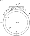
- a slip-ring assembly 100 comprises a slip-ring module 110 and a slip-ring brush block 120.
- the slip-ring module 110 may rotate about the rotation axis 15 and preferably comprises an insulating body 10, having a plurality of sliding tracks.
- four sliding tracks 11, 12, 13, and 14 are shown. It is obvious, that there may be any other number of sliding tracks.
- the sliding tracks are embedded and/or held by the insulating body. Preferably, the sliding tracks are insulated against each other. There may also be configurations, where at least some of the sliding tracks are connected together electrically. This may be useful for transferring higher currents or signals with a lower noise level.
- a preferred embodiment of sliding tracks having V-shaped grooves is shown. These V-grooves have the advantage that they can guide wires sliding on them and keep them precisely on a predetermined track. It is obvious that any other type of sliding track may be used instead, like tracks having multiple grooves or tracks without grooves, having a plane surface.
- the slip-ring brush block comprises a brush carrier 20 which may comprise a printed circuit board or any other insulating material. It may also comprise a conducting material like a metal, with insulated portions for holding the brushes.
- the brush block preferably holds a plurality of sliding brushes. In this embodiment, four wire brushes 21, 22, 23, 24 are shown. It is obvious, that there may be any other number of brushes and any other kind of brushes. For example, there may be multi-fiber brushes or carbon brushes.
- the brushes are spaced such that they fit to corresponding sliding tracks of the slip-ring module. There must not necessarily be one brush per sliding track. There may also be a plurality of brushes contacting a sliding track to increase current capability and/or reduce noise and/or contact resistance.
- a first absorbing device 201 is provided at the four wire brushes 21, 22, 23, 24 to reduce vibrations and/or oscillations.
- the first absorbing device 201 may only cover a smaller number of brushes, or there may be multiple absorbing devices, each device covering a smaller number of brushes.
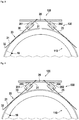
- FIG 2 a sectional view of the first embodiment is shown in a plane cut through lines A-A in figure 1 .
- the slip-ring module has a free bore, for example for carrying cables.
- a connector 16 is shown, which may be a soldering point or soldering pin or a connector, which contacts the first sliding track 11.
- a connecting cable may be soldered to this connector.
- the other sliding tracks also have connectors to contact the sliding tracks from the inner side of the insulating body.
- first sliding brush 21 and fifth sliding brush 25 contact first sliding track 11.
- a first absorbing device 201 and a second absorbing device 202 are shown.
- details of a general sliding brush 30 are shown.
- the sliding brush 30 has a first end 31 by which it is preferably held by a brush carrier 20. Opposing thereto is a second end 32. Between the first end 31 and the second end 32 is a contact section 33. This contact section is designed for contacting the sliding track. Preferably, an absorbing device 201 is arranged between the first end and the contact section.
- figure 3 a detail of figure 2 is shown. Here, details of the absorbing devices can be better seen.
- Figure 4 shows a slightly modified embodiment of figure 3 .
- the absorbing devices 201, 202 are held by first fixation means 203 and second fixation means 204 to the brush carrier.
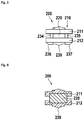
- FIG 5 a short side view of an absorbing device 200 is shown.
- the absorbing device has a housing 210 comprising a first housing part 211 and a second housing part 212. Details of the housing parts be shown in more detail later.
- Figure 6 shows a sectional view of figure 5 . This clearly shows the elastic absorbing material 220 between the housing parts.
- the fillet 239 is beneficial for larger housing parts as it increases stability.
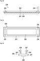
- Figure 7 shows a top view of the housing.
- Figure 8 shows a side view of the housing.
- Figure 9 shows a sectional side view. This also shows, how two identical housing parts 211, 212 are connected together to form a housing.
- a second housing part may be placed upside down and rotated about 180 degrees on a first housing part.
- the elastic absorbing material 220 may comprise a first layer 221 and a second layer 222. There may also be any other number of layers.
- the absorbing material parts are dimensioned in such a way that they enclose the sliding brushes when the housing parts are connected mechanically to a housing.
- Figure 10 shows a sectional side view of a housing part 230. It has a base 231 with a groove 232 for the elastic absorbing material (not shown here) and a fillet 239 for increasing stability.
- cantilever snap arms 234, 235 at one side and a matching opening 233 at the other side are provided.
- Figure 11 shows a top view of a housing part.
- Figure 12 shows a front view of a housing part.
- a first cantilever snap arm 234 having a first projection 236 and a second cantilever snap arm 235 having a second projection 237 are shown.
Landscapes
- Engineering & Computer Science (AREA)
- Chemical & Material Sciences (AREA)
- General Engineering & Computer Science (AREA)
- Ceramic Engineering (AREA)
- Combustion & Propulsion (AREA)
- Physics & Mathematics (AREA)
- Acoustics & Sound (AREA)
- Aviation & Aerospace Engineering (AREA)
- Mechanical Engineering (AREA)
- Motor Or Generator Current Collectors (AREA)
Priority Applications (3)
| Application Number | Priority Date | Filing Date | Title |
|---|---|---|---|
| EP17200075.4A EP3480901B1 (de) | 2017-11-06 | 2017-11-06 | Schwingungsdämpfende vorrichtung für gleitringbürsten |
| US16/179,525 US10833467B2 (en) | 2017-11-06 | 2018-11-02 | Vibration absorbing device for slip-ring brushes |
| CN201811309707.5A CN109755832B (zh) | 2017-11-06 | 2018-11-06 | 用于滑环电刷的振动吸收装置 |
Applications Claiming Priority (1)
| Application Number | Priority Date | Filing Date | Title |
|---|---|---|---|
| EP17200075.4A EP3480901B1 (de) | 2017-11-06 | 2017-11-06 | Schwingungsdämpfende vorrichtung für gleitringbürsten |
Publications (2)
| Publication Number | Publication Date |
|---|---|
| EP3480901A1 true EP3480901A1 (de) | 2019-05-08 |
| EP3480901B1 EP3480901B1 (de) | 2020-02-19 |
Family
ID=60262815
Family Applications (1)
| Application Number | Title | Priority Date | Filing Date |
|---|---|---|---|
| EP17200075.4A Active EP3480901B1 (de) | 2017-11-06 | 2017-11-06 | Schwingungsdämpfende vorrichtung für gleitringbürsten |
Country Status (3)
| Country | Link |
|---|---|
| US (1) | US10833467B2 (de) |
| EP (1) | EP3480901B1 (de) |
| CN (1) | CN109755832B (de) |
Cited By (1)
| Publication number | Priority date | Publication date | Assignee | Title |
|---|---|---|---|---|
| CN111817099A (zh) * | 2020-08-26 | 2020-10-23 | 徐洪杰 | 一种整体平板电刷式导电滑环 |
Citations (7)
| Publication number | Priority date | Publication date | Assignee | Title |
|---|---|---|---|---|
| JPS50144202U (de) * | 1974-05-15 | 1975-11-28 | ||
| JPS56139373U (de) * | 1980-03-19 | 1981-10-21 | ||
| JPS598275U (ja) * | 1982-07-01 | 1984-01-19 | アルプス電気株式会社 | 直流モ−タのブラシ装置 |
| JPH01132075A (ja) * | 1987-11-17 | 1989-05-24 | Mitsubishi Electric Corp | 摺動接触装置 |
| EP0662736A1 (de) | 1994-01-10 | 1995-07-12 | Air Precision S.A. | Drehender elektrischer Schleifring mit Mehrdrahtbürsten |
| JPH0993877A (ja) * | 1995-09-27 | 1997-04-04 | Asmo Co Ltd | モータブラシの支持構造 |
| US20030015934A1 (en) * | 2001-07-18 | 2003-01-23 | Hajime Kobayashi | Axial direction sliding-contact type brush apparatus, manufacturing method thereof, and flat motor having the brush apparatus |
Family Cites Families (29)
| Publication number | Priority date | Publication date | Assignee | Title |
|---|---|---|---|---|
| US3049637A (en) * | 1959-10-30 | 1962-08-14 | Schunk & Ebe Gmbh | Brush holders for electrical machinery |
| NL7113387A (de) * | 1971-09-30 | 1973-04-03 | ||
| US3833404A (en) * | 1972-05-31 | 1974-09-03 | Research Corp | Vibration or sound damping coating for vibratory structures |
| CH571283A5 (de) * | 1974-04-17 | 1975-12-31 | Bbc Brown Boveri & Cie | |
| JPS5236321B2 (de) | 1974-05-10 | 1977-09-14 | ||
| IT1012948B (it) * | 1974-05-30 | 1977-03-10 | Montedison Spa | Derivati solfonici a struttura poliossapolifluoroalcanica e procedimento per la loro prepar zione |
| JPS5510112B2 (de) * | 1974-10-11 | 1980-03-13 | ||
| GB2013417B (en) * | 1978-01-30 | 1983-01-12 | Papst Motoren Kg | Electrical machine |
| FI800698A (fi) | 1980-03-07 | 1981-09-08 | Waertsilae Oy Ab | Haenglaos |
| DE3142879A1 (de) * | 1981-10-29 | 1983-05-11 | Robert Bosch Gmbh, 7000 Stuttgart | Schleifkontakteinrichtung mit einer kohlebuerste |
| JPS598275A (ja) | 1982-07-02 | 1984-01-17 | Japan Storage Battery Co Ltd | 塩化チオニル・リチウム電池 |
| JPS6135135A (ja) * | 1984-07-26 | 1986-02-19 | Mabuchi Motor Co Ltd | 小型モ−タのブラシ防振装置 |
| JPH065974B2 (ja) * | 1985-04-19 | 1994-01-19 | 松下電器産業株式会社 | 小型モ−タの刷子制振材 |
| US20030155836A1 (en) * | 1985-07-31 | 2003-08-21 | Shigenori Uda | Small-size motor |
| JPH0753018B2 (ja) * | 1985-11-28 | 1995-06-05 | マブチモーター株式会社 | 小型モータのブラシ防振装置 |
| JPH0440604A (ja) * | 1990-06-06 | 1992-02-12 | Pioneer Electron Corp | 電流伝達機構 |
| JPH05326095A (ja) * | 1992-05-15 | 1993-12-10 | Toshiba Corp | スリップリング装置 |
| JPH05342543A (ja) * | 1992-06-12 | 1993-12-24 | Sony Corp | 回転体の電気的接続のためのブラシの支持構造 |
| GB9319740D0 (en) * | 1993-09-24 | 1993-11-10 | Johnson Electric Sa | Brush gear for a miniature electric motor |
| US5777405A (en) * | 1994-10-05 | 1998-07-07 | Matsushita Electric Industrial Co., Ltd. | Damping member for minimotor and minimotor equipped with the same |
| US6809455B2 (en) * | 2000-03-14 | 2004-10-26 | Api Portscap | Brush holder comprising brushes with contact tabs, spring and damping element |
| DE102009013084A1 (de) * | 2009-03-13 | 2010-06-10 | Siemens Aktiengesellschaft | Schleiffeder-Kontaktsystem |
| DE102011006820A1 (de) * | 2011-04-06 | 2012-10-11 | Schleifring Und Apparatebau Gmbh | Vibrationsfeste Schleifringanordnung |
| DE102011077358B3 (de) * | 2011-06-10 | 2012-12-06 | Schleifring Und Apparatebau Gmbh | Schwingungsunempfindlicher Bürstenblock für Schleifringe |
| DE102012203842B3 (de) * | 2012-03-12 | 2013-09-05 | Schleifring Und Apparatebau Gmbh | Schleifringbürste und Halter für Schleifringbürste |
| CN202651583U (zh) | 2012-05-29 | 2013-01-02 | 四川精通电气设备有限公司 | 一种防止摩擦产生绝缘附着物的导电滑环 |
| WO2016059105A2 (en) | 2014-10-14 | 2016-04-21 | Schleifring Und Apparatebau Gmbh | Slip-ring with wear monitoring |
| JP6425254B2 (ja) * | 2016-09-02 | 2018-11-21 | ミネベアミツミ株式会社 | モータ |
| JP6457987B2 (ja) * | 2016-09-02 | 2019-01-23 | ミネベアミツミ株式会社 | モータ、そのモータを備える回転装置及びその回転装置を備えた空調システムを備える車両 |
-
2017
- 2017-11-06 EP EP17200075.4A patent/EP3480901B1/de active Active
-
2018
- 2018-11-02 US US16/179,525 patent/US10833467B2/en active Active
- 2018-11-06 CN CN201811309707.5A patent/CN109755832B/zh active Active
Patent Citations (7)
| Publication number | Priority date | Publication date | Assignee | Title |
|---|---|---|---|---|
| JPS50144202U (de) * | 1974-05-15 | 1975-11-28 | ||
| JPS56139373U (de) * | 1980-03-19 | 1981-10-21 | ||
| JPS598275U (ja) * | 1982-07-01 | 1984-01-19 | アルプス電気株式会社 | 直流モ−タのブラシ装置 |
| JPH01132075A (ja) * | 1987-11-17 | 1989-05-24 | Mitsubishi Electric Corp | 摺動接触装置 |
| EP0662736A1 (de) | 1994-01-10 | 1995-07-12 | Air Precision S.A. | Drehender elektrischer Schleifring mit Mehrdrahtbürsten |
| JPH0993877A (ja) * | 1995-09-27 | 1997-04-04 | Asmo Co Ltd | モータブラシの支持構造 |
| US20030015934A1 (en) * | 2001-07-18 | 2003-01-23 | Hajime Kobayashi | Axial direction sliding-contact type brush apparatus, manufacturing method thereof, and flat motor having the brush apparatus |
Cited By (2)
| Publication number | Priority date | Publication date | Assignee | Title |
|---|---|---|---|---|
| CN111817099A (zh) * | 2020-08-26 | 2020-10-23 | 徐洪杰 | 一种整体平板电刷式导电滑环 |
| CN111817099B (zh) * | 2020-08-26 | 2022-02-01 | 徐洪杰 | 一种整体平板电刷式导电滑环 |
Also Published As
| Publication number | Publication date |
|---|---|
| CN109755832A (zh) | 2019-05-14 |
| CN109755832B (zh) | 2021-07-23 |
| US10833467B2 (en) | 2020-11-10 |
| EP3480901B1 (de) | 2020-02-19 |
| US20190190221A1 (en) | 2019-06-20 |
Similar Documents
| Publication | Publication Date | Title |
|---|---|---|
| US7719158B2 (en) | Slip-ring brush and slip-ring unit equipped with such a slip-ring brush | |
| US9281648B2 (en) | Brush block for a slipring | |
| JP4954001B2 (ja) | 多芯ケーブルコネクタ | |
| JP5209460B2 (ja) | 同軸コネクタ | |
| US9190769B2 (en) | Cable connecting apparatus, cable assembly, and method of making cable assembly | |
| US10424889B2 (en) | Stabilized gold wire brush for sliprings | |
| US11658449B2 (en) | Slipring with wear monitoring | |
| JP4956670B2 (ja) | 電気的な差し込みコネクタ | |
| JP2005354858A (ja) | アクチュエータ | |
| KR20010029618A (ko) | 온도 센서, 온도 센서의 제조 방법, 및 온도 센서를 회로기판에 장착하는 방법 | |
| CN110148866B (zh) | 导电滑环 | |
| CN105706308A (zh) | 电连接装置 | |
| CN111200225A (zh) | 滑环机构 | |
| US9490600B2 (en) | High current slipring for multi fiber brushes | |
| US10833467B2 (en) | Vibration absorbing device for slip-ring brushes | |
| US20200243996A1 (en) | Electrical plug contact for high-current applications and electrical connector system for high-current applications | |
| EP2696450B1 (de) | Günstig herstellbare Bürste mit goldbeschichtetem Draht | |
| US8314522B2 (en) | Printed circuit board with ground conductor for electric motor, and electric motor | |
| US9093808B2 (en) | Vibration-resistant slip ring device | |
| CN217115111U (zh) | 用于精密导电滑环的新型点接触式环刷匹配结构 | |
| KR20080090278A (ko) | 실드 전선의 접속 구조 | |
| US8986053B2 (en) | Slip ring brush and holder for slip ring brush | |
| JP2006333573A (ja) | ケーブルクランプ及び携帯用電子機器 | |
| WO2008070104A2 (en) | Usb connector assembly | |
| EP3364508A1 (de) | Halter für schleifringbürsten |
Legal Events
| Date | Code | Title | Description |
|---|---|---|---|
| STAA | Information on the status of an ep patent application or granted ep patent |
Free format text: STATUS: EXAMINATION IS IN PROGRESS |
|
| PUAI | Public reference made under article 153(3) epc to a published international application that has entered the european phase |
Free format text: ORIGINAL CODE: 0009012 |
|
| 17P | Request for examination filed |
Effective date: 20180502 |
|
| AK | Designated contracting states |
Kind code of ref document: A1 Designated state(s): AL AT BE BG CH CY CZ DE DK EE ES FI FR GB GR HR HU IE IS IT LI LT LU LV MC MK MT NL NO PL PT RO RS SE SI SK SM TR |
|
| AX | Request for extension of the european patent |
Extension state: BA ME |
|
| RBV | Designated contracting states (corrected) |
Designated state(s): AL AT BE BG CH CY CZ DE DK EE ES FI FR GB GR HR HU IE IS IT LI LT LU LV MC MK MT NL NO PL PT RO RS SE SI SK SM TR |
|
| GRAP | Despatch of communication of intention to grant a patent |
Free format text: ORIGINAL CODE: EPIDOSNIGR1 |
|
| STAA | Information on the status of an ep patent application or granted ep patent |
Free format text: STATUS: GRANT OF PATENT IS INTENDED |
|
| INTG | Intention to grant announced |
Effective date: 20190930 |
|
| GRAS | Grant fee paid |
Free format text: ORIGINAL CODE: EPIDOSNIGR3 |
|
| GRAA | (expected) grant |
Free format text: ORIGINAL CODE: 0009210 |
|
| STAA | Information on the status of an ep patent application or granted ep patent |
Free format text: STATUS: THE PATENT HAS BEEN GRANTED |
|
| AK | Designated contracting states |
Kind code of ref document: B1 Designated state(s): AL AT BE BG CH CY CZ DE DK EE ES FI FR GB GR HR HU IE IS IT LI LT LU LV MC MK MT NL NO PL PT RO RS SE SI SK SM TR |
|
| REG | Reference to a national code |
Ref country code: CH Ref legal event code: EP |
|
| REG | Reference to a national code |
Ref country code: DE Ref legal event code: R096 Ref document number: 602017011919 Country of ref document: DE |
|
| REG | Reference to a national code |
Ref country code: AT Ref legal event code: REF Ref document number: 1236025 Country of ref document: AT Kind code of ref document: T Effective date: 20200315 |
|
| REG | Reference to a national code |
Ref country code: IE Ref legal event code: FG4D |
|
| REG | Reference to a national code |
Ref country code: NL Ref legal event code: MP Effective date: 20200219 |
|
| PG25 | Lapsed in a contracting state [announced via postgrant information from national office to epo] |
Ref country code: FI Free format text: LAPSE BECAUSE OF FAILURE TO SUBMIT A TRANSLATION OF THE DESCRIPTION OR TO PAY THE FEE WITHIN THE PRESCRIBED TIME-LIMIT Effective date: 20200219 Ref country code: RS Free format text: LAPSE BECAUSE OF FAILURE TO SUBMIT A TRANSLATION OF THE DESCRIPTION OR TO PAY THE FEE WITHIN THE PRESCRIBED TIME-LIMIT Effective date: 20200219 Ref country code: NO Free format text: LAPSE BECAUSE OF FAILURE TO SUBMIT A TRANSLATION OF THE DESCRIPTION OR TO PAY THE FEE WITHIN THE PRESCRIBED TIME-LIMIT Effective date: 20200519 |
|
| REG | Reference to a national code |
Ref country code: LT Ref legal event code: MG4D |
|
| PG25 | Lapsed in a contracting state [announced via postgrant information from national office to epo] |
Ref country code: IS Free format text: LAPSE BECAUSE OF FAILURE TO SUBMIT A TRANSLATION OF THE DESCRIPTION OR TO PAY THE FEE WITHIN THE PRESCRIBED TIME-LIMIT Effective date: 20200619 Ref country code: GR Free format text: LAPSE BECAUSE OF FAILURE TO SUBMIT A TRANSLATION OF THE DESCRIPTION OR TO PAY THE FEE WITHIN THE PRESCRIBED TIME-LIMIT Effective date: 20200520 Ref country code: BG Free format text: LAPSE BECAUSE OF FAILURE TO SUBMIT A TRANSLATION OF THE DESCRIPTION OR TO PAY THE FEE WITHIN THE PRESCRIBED TIME-LIMIT Effective date: 20200519 Ref country code: LV Free format text: LAPSE BECAUSE OF FAILURE TO SUBMIT A TRANSLATION OF THE DESCRIPTION OR TO PAY THE FEE WITHIN THE PRESCRIBED TIME-LIMIT Effective date: 20200219 Ref country code: SE Free format text: LAPSE BECAUSE OF FAILURE TO SUBMIT A TRANSLATION OF THE DESCRIPTION OR TO PAY THE FEE WITHIN THE PRESCRIBED TIME-LIMIT Effective date: 20200219 Ref country code: HR Free format text: LAPSE BECAUSE OF FAILURE TO SUBMIT A TRANSLATION OF THE DESCRIPTION OR TO PAY THE FEE WITHIN THE PRESCRIBED TIME-LIMIT Effective date: 20200219 |
|
| PG25 | Lapsed in a contracting state [announced via postgrant information from national office to epo] |
Ref country code: NL Free format text: LAPSE BECAUSE OF FAILURE TO SUBMIT A TRANSLATION OF THE DESCRIPTION OR TO PAY THE FEE WITHIN THE PRESCRIBED TIME-LIMIT Effective date: 20200219 |
|
| PG25 | Lapsed in a contracting state [announced via postgrant information from national office to epo] |
Ref country code: DK Free format text: LAPSE BECAUSE OF FAILURE TO SUBMIT A TRANSLATION OF THE DESCRIPTION OR TO PAY THE FEE WITHIN THE PRESCRIBED TIME-LIMIT Effective date: 20200219 Ref country code: RO Free format text: LAPSE BECAUSE OF FAILURE TO SUBMIT A TRANSLATION OF THE DESCRIPTION OR TO PAY THE FEE WITHIN THE PRESCRIBED TIME-LIMIT Effective date: 20200219 Ref country code: SK Free format text: LAPSE BECAUSE OF FAILURE TO SUBMIT A TRANSLATION OF THE DESCRIPTION OR TO PAY THE FEE WITHIN THE PRESCRIBED TIME-LIMIT Effective date: 20200219 Ref country code: PT Free format text: LAPSE BECAUSE OF FAILURE TO SUBMIT A TRANSLATION OF THE DESCRIPTION OR TO PAY THE FEE WITHIN THE PRESCRIBED TIME-LIMIT Effective date: 20200712 Ref country code: SM Free format text: LAPSE BECAUSE OF FAILURE TO SUBMIT A TRANSLATION OF THE DESCRIPTION OR TO PAY THE FEE WITHIN THE PRESCRIBED TIME-LIMIT Effective date: 20200219 Ref country code: EE Free format text: LAPSE BECAUSE OF FAILURE TO SUBMIT A TRANSLATION OF THE DESCRIPTION OR TO PAY THE FEE WITHIN THE PRESCRIBED TIME-LIMIT Effective date: 20200219 Ref country code: LT Free format text: LAPSE BECAUSE OF FAILURE TO SUBMIT A TRANSLATION OF THE DESCRIPTION OR TO PAY THE FEE WITHIN THE PRESCRIBED TIME-LIMIT Effective date: 20200219 Ref country code: CZ Free format text: LAPSE BECAUSE OF FAILURE TO SUBMIT A TRANSLATION OF THE DESCRIPTION OR TO PAY THE FEE WITHIN THE PRESCRIBED TIME-LIMIT Effective date: 20200219 Ref country code: ES Free format text: LAPSE BECAUSE OF FAILURE TO SUBMIT A TRANSLATION OF THE DESCRIPTION OR TO PAY THE FEE WITHIN THE PRESCRIBED TIME-LIMIT Effective date: 20200219 |
|
| REG | Reference to a national code |
Ref country code: AT Ref legal event code: MK05 Ref document number: 1236025 Country of ref document: AT Kind code of ref document: T Effective date: 20200219 |
|
| REG | Reference to a national code |
Ref country code: DE Ref legal event code: R097 Ref document number: 602017011919 Country of ref document: DE |
|
| PLBE | No opposition filed within time limit |
Free format text: ORIGINAL CODE: 0009261 |
|
| STAA | Information on the status of an ep patent application or granted ep patent |
Free format text: STATUS: NO OPPOSITION FILED WITHIN TIME LIMIT |
|
| 26N | No opposition filed |
Effective date: 20201120 |
|
| PG25 | Lapsed in a contracting state [announced via postgrant information from national office to epo] |
Ref country code: IT Free format text: LAPSE BECAUSE OF FAILURE TO SUBMIT A TRANSLATION OF THE DESCRIPTION OR TO PAY THE FEE WITHIN THE PRESCRIBED TIME-LIMIT Effective date: 20200219 Ref country code: AT Free format text: LAPSE BECAUSE OF FAILURE TO SUBMIT A TRANSLATION OF THE DESCRIPTION OR TO PAY THE FEE WITHIN THE PRESCRIBED TIME-LIMIT Effective date: 20200219 |
|
| PG25 | Lapsed in a contracting state [announced via postgrant information from national office to epo] |
Ref country code: SI Free format text: LAPSE BECAUSE OF FAILURE TO SUBMIT A TRANSLATION OF THE DESCRIPTION OR TO PAY THE FEE WITHIN THE PRESCRIBED TIME-LIMIT Effective date: 20200219 Ref country code: PL Free format text: LAPSE BECAUSE OF FAILURE TO SUBMIT A TRANSLATION OF THE DESCRIPTION OR TO PAY THE FEE WITHIN THE PRESCRIBED TIME-LIMIT Effective date: 20200219 |
|
| PG25 | Lapsed in a contracting state [announced via postgrant information from national office to epo] |
Ref country code: MC Free format text: LAPSE BECAUSE OF FAILURE TO SUBMIT A TRANSLATION OF THE DESCRIPTION OR TO PAY THE FEE WITHIN THE PRESCRIBED TIME-LIMIT Effective date: 20200219 |
|
| REG | Reference to a national code |
Ref country code: CH Ref legal event code: PL |
|
| PG25 | Lapsed in a contracting state [announced via postgrant information from national office to epo] |
Ref country code: LU Free format text: LAPSE BECAUSE OF NON-PAYMENT OF DUE FEES Effective date: 20201106 |
|
| REG | Reference to a national code |
Ref country code: BE Ref legal event code: MM Effective date: 20201130 |
|
| PG25 | Lapsed in a contracting state [announced via postgrant information from national office to epo] |
Ref country code: LI Free format text: LAPSE BECAUSE OF NON-PAYMENT OF DUE FEES Effective date: 20201130 Ref country code: CH Free format text: LAPSE BECAUSE OF NON-PAYMENT OF DUE FEES Effective date: 20201130 |
|
| PG25 | Lapsed in a contracting state [announced via postgrant information from national office to epo] |
Ref country code: IE Free format text: LAPSE BECAUSE OF NON-PAYMENT OF DUE FEES Effective date: 20201106 |
|
| PG25 | Lapsed in a contracting state [announced via postgrant information from national office to epo] |
Ref country code: TR Free format text: LAPSE BECAUSE OF FAILURE TO SUBMIT A TRANSLATION OF THE DESCRIPTION OR TO PAY THE FEE WITHIN THE PRESCRIBED TIME-LIMIT Effective date: 20200219 Ref country code: MT Free format text: LAPSE BECAUSE OF FAILURE TO SUBMIT A TRANSLATION OF THE DESCRIPTION OR TO PAY THE FEE WITHIN THE PRESCRIBED TIME-LIMIT Effective date: 20200219 Ref country code: CY Free format text: LAPSE BECAUSE OF FAILURE TO SUBMIT A TRANSLATION OF THE DESCRIPTION OR TO PAY THE FEE WITHIN THE PRESCRIBED TIME-LIMIT Effective date: 20200219 |
|
| PG25 | Lapsed in a contracting state [announced via postgrant information from national office to epo] |
Ref country code: MK Free format text: LAPSE BECAUSE OF FAILURE TO SUBMIT A TRANSLATION OF THE DESCRIPTION OR TO PAY THE FEE WITHIN THE PRESCRIBED TIME-LIMIT Effective date: 20200219 Ref country code: AL Free format text: LAPSE BECAUSE OF FAILURE TO SUBMIT A TRANSLATION OF THE DESCRIPTION OR TO PAY THE FEE WITHIN THE PRESCRIBED TIME-LIMIT Effective date: 20200219 |
|
| PG25 | Lapsed in a contracting state [announced via postgrant information from national office to epo] |
Ref country code: BE Free format text: LAPSE BECAUSE OF NON-PAYMENT OF DUE FEES Effective date: 20201130 |
|
| PGFP | Annual fee paid to national office [announced via postgrant information from national office to epo] |
Ref country code: GB Payment date: 20231123 Year of fee payment: 7 |
|
| PGFP | Annual fee paid to national office [announced via postgrant information from national office to epo] |
Ref country code: FR Payment date: 20231124 Year of fee payment: 7 Ref country code: DE Payment date: 20231123 Year of fee payment: 7 |