EP3480143B1 - Transportvorrichtung - Google Patents
Transportvorrichtung Download PDFInfo
- Publication number
- EP3480143B1 EP3480143B1 EP16907399.6A EP16907399A EP3480143B1 EP 3480143 B1 EP3480143 B1 EP 3480143B1 EP 16907399 A EP16907399 A EP 16907399A EP 3480143 B1 EP3480143 B1 EP 3480143B1
- Authority
- EP
- European Patent Office
- Prior art keywords
- transfer
- transferred
- transfer module
- module
- transfer apparatus
- Prior art date
- Legal status (The legal status is an assumption and is not a legal conclusion. Google has not performed a legal analysis and makes no representation as to the accuracy of the status listed.)
- Active
Links
Images


Classifications
-
- B—PERFORMING OPERATIONS; TRANSPORTING
- B65—CONVEYING; PACKING; STORING; HANDLING THIN OR FILAMENTARY MATERIAL
- B65G—TRANSPORT OR STORAGE DEVICES, e.g. CONVEYORS FOR LOADING OR TIPPING, SHOP CONVEYOR SYSTEMS OR PNEUMATIC TUBE CONVEYORS
- B65G51/00—Conveying articles through pipes or tubes by fluid flow or pressure; Conveying articles over a flat surface, e.g. the base of a trough, by jets located in the surface
- B65G51/02—Directly conveying the articles, e.g. slips, sheets, stockings, containers or workpieces, by flowing gases
- B65G51/03—Directly conveying the articles, e.g. slips, sheets, stockings, containers or workpieces, by flowing gases over a flat surface or in troughs
-
- B—PERFORMING OPERATIONS; TRANSPORTING
- B65—CONVEYING; PACKING; STORING; HANDLING THIN OR FILAMENTARY MATERIAL
- B65G—TRANSPORT OR STORAGE DEVICES, e.g. CONVEYORS FOR LOADING OR TIPPING, SHOP CONVEYOR SYSTEMS OR PNEUMATIC TUBE CONVEYORS
- B65G13/00—Roller-ways
- B65G13/11—Roller frames
-
- B—PERFORMING OPERATIONS; TRANSPORTING
- B65—CONVEYING; PACKING; STORING; HANDLING THIN OR FILAMENTARY MATERIAL
- B65G—TRANSPORT OR STORAGE DEVICES, e.g. CONVEYORS FOR LOADING OR TIPPING, SHOP CONVEYOR SYSTEMS OR PNEUMATIC TUBE CONVEYORS
- B65G21/00—Supporting or protective framework or housings for endless load-carriers or traction elements of belt or chain conveyors
- B65G21/10—Supporting or protective framework or housings for endless load-carriers or traction elements of belt or chain conveyors movable, or having interchangeable or relatively movable parts; Devices for moving framework or parts thereof
-
- B—PERFORMING OPERATIONS; TRANSPORTING
- B65—CONVEYING; PACKING; STORING; HANDLING THIN OR FILAMENTARY MATERIAL
- B65G—TRANSPORT OR STORAGE DEVICES, e.g. CONVEYORS FOR LOADING OR TIPPING, SHOP CONVEYOR SYSTEMS OR PNEUMATIC TUBE CONVEYORS
- B65G21/00—Supporting or protective framework or housings for endless load-carriers or traction elements of belt or chain conveyors
- B65G21/20—Means incorporated in, or attached to, framework or housings for guiding load-carriers, traction elements or loads supported on moving surfaces
- B65G21/2027—Suction retaining means
- B65G21/2036—Suction retaining means for retaining the load on the load-carrying surface
-
- B—PERFORMING OPERATIONS; TRANSPORTING
- B65—CONVEYING; PACKING; STORING; HANDLING THIN OR FILAMENTARY MATERIAL
- B65G—TRANSPORT OR STORAGE DEVICES, e.g. CONVEYORS FOR LOADING OR TIPPING, SHOP CONVEYOR SYSTEMS OR PNEUMATIC TUBE CONVEYORS
- B65G21/00—Supporting or protective framework or housings for endless load-carriers or traction elements of belt or chain conveyors
- B65G21/20—Means incorporated in, or attached to, framework or housings for guiding load-carriers, traction elements or loads supported on moving surfaces
- B65G21/2045—Mechanical means for guiding or retaining the load on the load-carrying surface
- B65G21/2063—Mechanical means for guiding or retaining the load on the load-carrying surface comprising elements not movable in the direction of load-transport
- B65G21/209—Mechanical means for guiding or retaining the load on the load-carrying surface comprising elements not movable in the direction of load-transport for augmenting or creating a pression force between the load and the load-carrying surface
-
- B—PERFORMING OPERATIONS; TRANSPORTING
- B65—CONVEYING; PACKING; STORING; HANDLING THIN OR FILAMENTARY MATERIAL
- B65G—TRANSPORT OR STORAGE DEVICES, e.g. CONVEYORS FOR LOADING OR TIPPING, SHOP CONVEYOR SYSTEMS OR PNEUMATIC TUBE CONVEYORS
- B65G37/00—Combinations of mechanical conveyors of the same kind, or of different kinds, of interest apart from their application in particular machines or use in particular manufacturing processes
- B65G37/005—Combinations of mechanical conveyors of the same kind, or of different kinds, of interest apart from their application in particular machines or use in particular manufacturing processes comprising two or more co-operating conveying elements with parallel longitudinal axes
-
- B—PERFORMING OPERATIONS; TRANSPORTING
- B65—CONVEYING; PACKING; STORING; HANDLING THIN OR FILAMENTARY MATERIAL
- B65G—TRANSPORT OR STORAGE DEVICES, e.g. CONVEYORS FOR LOADING OR TIPPING, SHOP CONVEYOR SYSTEMS OR PNEUMATIC TUBE CONVEYORS
- B65G47/00—Article or material-handling devices associated with conveyors; Methods employing such devices
- B65G47/22—Devices influencing the relative position or the attitude of articles during transit by conveyors
- B65G47/24—Devices influencing the relative position or the attitude of articles during transit by conveyors orientating the articles
- B65G47/244—Devices influencing the relative position or the attitude of articles during transit by conveyors orientating the articles by turning them about an axis substantially perpendicular to the conveying plane
- B65G47/2445—Devices influencing the relative position or the attitude of articles during transit by conveyors orientating the articles by turning them about an axis substantially perpendicular to the conveying plane by means of at least two co-operating endless conveying elements
-
- B—PERFORMING OPERATIONS; TRANSPORTING
- B65—CONVEYING; PACKING; STORING; HANDLING THIN OR FILAMENTARY MATERIAL
- B65G—TRANSPORT OR STORAGE DEVICES, e.g. CONVEYORS FOR LOADING OR TIPPING, SHOP CONVEYOR SYSTEMS OR PNEUMATIC TUBE CONVEYORS
- B65G47/00—Article or material-handling devices associated with conveyors; Methods employing such devices
- B65G47/52—Devices for transferring articles or materials between conveyors i.e. discharging or feeding devices
- B65G47/68—Devices for transferring articles or materials between conveyors i.e. discharging or feeding devices adapted to receive articles arriving in one layer from one conveyor lane and to transfer them in individual layers to more than one conveyor lane or to one broader conveyor lane, or vice versa, e.g. combining the flows of articles conveyed by more than one conveyor
- B65G47/682—Devices for transferring articles or materials between conveyors i.e. discharging or feeding devices adapted to receive articles arriving in one layer from one conveyor lane and to transfer them in individual layers to more than one conveyor lane or to one broader conveyor lane, or vice versa, e.g. combining the flows of articles conveyed by more than one conveyor from a single conveyor lane consisting of one conveyor or several adjacent conveyors
-
- B—PERFORMING OPERATIONS; TRANSPORTING
- B65—CONVEYING; PACKING; STORING; HANDLING THIN OR FILAMENTARY MATERIAL
- B65G—TRANSPORT OR STORAGE DEVICES, e.g. CONVEYORS FOR LOADING OR TIPPING, SHOP CONVEYOR SYSTEMS OR PNEUMATIC TUBE CONVEYORS
- B65G47/00—Article or material-handling devices associated with conveyors; Methods employing such devices
- B65G47/74—Feeding, transfer, or discharging devices of particular kinds or types
- B65G47/76—Fixed or adjustable ploughs or transverse scrapers
- B65G47/763—Fixed ploughs or transverse scrapers
-
- B—PERFORMING OPERATIONS; TRANSPORTING
- B65—CONVEYING; PACKING; STORING; HANDLING THIN OR FILAMENTARY MATERIAL
- B65G—TRANSPORT OR STORAGE DEVICES, e.g. CONVEYORS FOR LOADING OR TIPPING, SHOP CONVEYOR SYSTEMS OR PNEUMATIC TUBE CONVEYORS
- B65G2201/00—Indexing codes relating to handling devices, e.g. conveyors, characterised by the type of product or load being conveyed or handled
- B65G2201/02—Articles
- B65G2201/0235—Containers
- B65G2201/025—Boxes
Definitions
- the present invention relates to a transfer apparatus, and more particularly, to a transfer apparatus which can transfer an object to be transferred by various methods and easily perform management and maintenance of the transfer apparatus.
- a method is widely used, which hold various articles on the top of a configuration including a roller or a belt and transfers the articles through rotation of the roller or belt.
- the roller and the belt directly contact the object to be transferred and are abraded by friction with the object to be transferred.
- US2006/163035 A1 disclosing the preamble of claim 1, relates to a method and device for pivoting plate elements travelling on a flat conveyor, the conveyor being provided with two parallel left and right paths, respective driven at different speeds.
- the paths define between them a separating line on which the plate elements are rotated around an axis by application of each of the two path speeds on a left portion of the plate element and on a right portion of the plate element defined by the separating line.
- the present invention is directed to provide a transfer apparatus which can transfer an object to be transferred by various methods and easily perform management and maintenance of the transfer apparatus.
- a transfer apparatus includes: a first transfer module holding an object to be transferred on the top thereof and transferring the object to be transferred at a first speed in a longitudinal direction; a second transfer module disposed in parallel with the first transfer module and holding the object to be transferred on the top thereof and transferring the object to be transferred at a second speed in the longitudinal direction; and a blowing module causing air to flow upward/downward below at least one of the first transfer module and the second transfer module.
- the blowing module may cause the air to flow downward while at least one of the first transfer module and the second transfer module transfers the object to be transferred.
- first transfer module and the second transfer module may be formed to move in a transverse direction.
- first speed and the second speed of the first transfer module and the second transfer module may be set to be different from each other.
- the transfer apparatus further includes a third transfer module disposed in parallel with the first transfer module and the second transfer module and transferring the object to be transferred in the longitudinal direction.
- the third transfer module is provided between the first transfer module and the second transfer module.
- the third transfer module may have a relatively smaller width than the first transfer module and the second transfer module
- the third transfer module includes a lower transfer unit transferring the object to be transferred by contacting the bottom of the object to be transferred and an upper transfer unit transferring the object to be transferred by contacting the top of the object to be transferred.
- the lower transfer unit and the upper transfer unit may be formed to move upward/downward so as to selectively contact the object to be transferred.
- the blowing module may cause the air to flow upward while the third transfer module transfers the object to be transferred.
- the transfer apparatus may further include a guide module of which the width decreases in a direction in which the object to be transferred is transferred so that the objects to be transferred, which the first and second transfer modules transfer, contact each other.
- objects to be transferred which have various shapes can be transferred by a desired method.
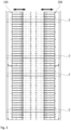
- FIG. 1 is a diagram illustrating a configuration of a transfer apparatus according to an exemplary embodiment of the present invention
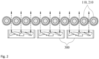
- FIG. 2 is a diagram illustrating a configuration of a blowing module of the transfer apparatus according to the exemplary embodiment of the present invention
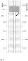
- FIG. 3 is a diagram illustrating a state in which a first transfer module and a second transfer module of the transfer apparatus are moving transversely according to the exemplary embodiment of the present invention
- FIG. 4 is a diagram illustrating a configuration of a third transfer module of the transfer apparatus according to the exemplary embodiment of the present invention.
- the apparatus as an apparatus for transferring an object to be transferred includes a first transfer module 100, a second transfer module 200, a blowing module 300, and a third transfer module 400.
- the present invention is not limited thereto and the transfer apparatus may be universally used in a flexible plate type object to be transferred and besides, the object to be transferred is not limited to the type of the object to be transferred and may be variously applied.
- the first transfer module 100 as a configuration that holds the object to be transferred on the top thereof and moves the object to be transferred transfers the object to be transferred at a first speed in the longitudinal direction.
- a plurality of rollers 110 are configured to be arranged, and as a result, each roller 110 may rotate and transfer the object to be transferred, which is held on the top in a rotational direction of the roller 110.
- the roller 110 is formed in a general cylindrical shape and various materials such as metal or rubber may be applied to the surface of each roller 110 according to characteristics of the object to be transferred.
- each roller 110 may be advantageous to rotate so as to transfer the object to be transferred at a first speed and all rollers 110 may be configured to rotate at the same speed or the respective rollers 110 may be configured to rotate at different speeds.
- the first speed may be advantageous to be configured so as to apply various speeds according to a configuration of a user.
- each roller 110 is disposed so that a predetermined interval is formed between adjacent rollers 110 may be advantageous to be formed so that air flows by penetrating the top and the bottom of the first transfer module 100.
- the configuration of the first transfer module 100 is not limited to the exemplary embodiment and may hold the object to be transferred on the top and transfer the object and if the configuration of the first transfer module 100 is formed so that the air is in communication between the top and the bottom, various types and configurations may be applied.
- the second transfer module 200 is a configuration for transferring the object to be transferred in the longitudinal direction by holding the object to be transferred on the top similarly to the first transfer module 100 and the second transfer module 200 transfers the object to be transferred at a second speed.
- the second speed may be set to be the same as the first speed of the first transfer module 100 or to be different from the first speed of the first transfer module 100.
- the second transfer module 200 as a similar configuration as the first transfer module 100 may be formed to have a configuration which is the same as the aforementioned configuration.
- the second transfer module 200 is formed in a form in which the plurality of rollers 210 is arranged and the respective rollers 210 are spaced apart from each other at a predetermined interval to be formed so that the air flows by penetrating the top and the bottom of the second transfer module 200.
- Such a configuration of the second transfer module 200 is not also limited to the exemplary embodiment and may hold the object to be transferred on the top and transfer the object and if the configuration of the second transfer module 200 is formed so that the air is in communication between the top and the bottom, various types and configurations may be applied.
- the second transfer module 200 is disposed in parallel to the first transfer module 100 to transfer a single object to be transferred together with the first transfer module 100 or a separate object to be transferred separately from the first transfer module 100.
- first transfer module 100 and the second transfer module 200 may be configured to move in the transverse direction.
- a frame F penetrating the first transfer module 100 and the second transfer module 200 in the transverse direction is provided and the first transfer module 100 and the second transfer module 200 may move in the transverse direction along the frame F.
- first transfer module 100 and the second transfer module 200 may be advantageously configured to include separate driving devices, respectively to separately move.
- a distance between the first transfer module 100 and the second transfer module 200 may be arbitrarily controlled.
- the blowing module 300 is a component that causes the air to flow upward/downward below at least one of the first transfer module 100 and the second transfer module 200.
- the blowing module 300 is provided below both the first transfer module 100 and the second transfer module 200 to cause the air to flow by penetrating the tops and the bottoms of the first transfer module 100 and the second transfer module 200.
- the blowing module 300 may be configured in a form in which a plurality of fans is provided below both the first transfer module 100 and the second transfer module 200 and configured to selectively generate the air to flow to the top or the bottom through a rotational direction of the fan.
- the flow of the air caused by the blowing module 300 influences the object to be transferred on the tops of the first transfer module 100 and the second transfer module 200 and the object to be transferred may be configured to be transferred by various methods.
- the third transfer module 400 as a component for transferring the object to be transferred in the longitudinal direction is disposed in parallel to the first transfer module 100 and the second transfer module 200 in parallel.
- the third transfer module 400 as a component that just transfers the object to be transferred in the longitudinal direction is configured to be disposed between the first transfer module 100 and the second transfer module 200.
- the third transfer module 400 is configured to include an upper transfer unit 410 and a lower transfer unit 420.
- the upper transfer unit 410 transfers the object to be transferred by contacting the top of the object to be transferred above the object to be transferred and the lower transfer unit 420 transfers the object to be transferred by contacting the bottom of the object to be transferred below the object to be transferred.
- the upper transfer unit 410 may be configured in such a manner that a plurality of rollers 412 which rotates is provided, a belt 414 having a form to wholly cover the rollers 412 is provided, and the belt 414 rotates together with the rotation of the roller 412.
- the upper transfer unit 410 may be configured in such a manner that one surface of the belt 414 contacts the top of the object to be transferred and the object to be transferred moves along the belt 414 by the rotation of the belt 414.
- the lower transfer unit 420 may also be configured in such a manner that a plurality of rollers 422 is provided, a belt 424 wholly covering the rollers 422 is provided, and the object to be transferred moves along the belt 424 by the rotation of the belt 424, similarly to the upper transfer unit 410.
- the object to be transferred may be transferred with movement of the belt of each component in a form in which the object to be transferred is wedged between the upper transfer unit 410 and the lower transfer unit 420.
- the upper transfer unit 410 and the lower transfer unit 420 may be advantageously formed to mutually move so as to selectively contact the object to be transferred.
- the upper transfer unit 410 moves upward at a portion where the object to be transferred is transferred to be spaced apart from the object to be transferred
- the lower transfer unit 420 moves downward at the portion where the object to be transferred is transferred to be spaced apart from the object to be transferred
- the third transfer module 400 may be selectively used in the course of transferring the object to be transferred.
- the third transfer module 400 may be advantageously formed to have a relatively smaller width than the first transfer module 100 and the second transfer module 200.
- the belts 414 and 424 provided in the third transfer module 400 may be formed to have a relatively smaller width than the first transfer module 100 and the second transfer module 200.
- the third transfer module 400 may be advantageously configured to move in the transverse direction similarly to the first transfer module 100 and the second transfer module 200.
- a user may achieve an effect to transfer the object to be transferred by various methods and easily perform management and maintenance of the transfer apparatus.
- FIGS. 5 to 8 are diagrams illustrating a first use aspect of the transfer apparatus according to the exemplary embodiment of the present invention.
- the first use aspect of the transfer apparatus relates to a component that transfers an object B to be transferred while rotating the object B to be transferred and in present use aspect, a plurality of transfer apparatuses may be configured to be connected to each other in series.
- the transfer apparatus provided at the front end among the plurality of transfer apparatuses connected in series includes a first transfer module 100a and a second transfer module 200a and the transfer apparatus provided at the rear end may include a first transfer module 100b and a second transfer module 200b.
- the object B to be transferred may be held on the top of the transfer apparatus provided at the front end among the plurality of transfer apparatuses connected in series.
- the object to be transferred is held on the tops of the first transfer module 100a and the second transfer module 200a and the first transfer module 100a and the second transfer module 200a may transfer the object B to be transferred together.
- the first speed at which the first transfer module 100a transfers the object B to be transferred and the second speed at which the second transfer module 200a transfers the object B to be transferred may be se to be different from each other.
- the first speed is set to be relatively higher than the second speed, and as a result, the speed at which the first transfer module 100a transfers the object B to be transferred may be configured to be higher than the speed at which the second transfer module 200a transfers the object B to be transferred.
- one side of the object B to be transferred is held on the top of the first transfer module 100a and the other side is held on the top of the second transfer module 200a, one side of the object B to be transferred may be transferred relatively rapidly.
- one side of the object B to be transferred which is held on the top of the first transfer module 100a is transferred to further the rear end than the other side, and as a result, the object B to be transferred may be transferred while rotating.
- the first speed and the second speed may be advantageously set so that the object B to be transferred reaches the rear end of the transfer apparatus provided at the front end.
- the upper transfer unit and the lower transfer unit of the third transfer module may advantageously move to be spaced apart from the object B to be transferred.
- the object B to be transferred, of which the rotation is completed may be transferred to the tops of the first transfer module 100b and the second transfer module 200b of the transfer apparatus provided at the rear end as illustrated in FIG. 7 .
- the center of gravity of the object B to be transferred which rotates may not be positioned at the center of the transfer apparatus according to the present invention according to the form and the layout of the object B to be transferred.
- the first transfer module 100b and the second transfer module 200b may move in the transverse direction so that the center of the object B to be transferred is positioned at the center of the transfer apparatus.
- an effect in which the object B to be transferred is evenly disposed on the tops of the first transfer module 100b and the second transfer module 200b to be stably transferred may be achieved.
- the first speed and the second speed are set to be the same as each other, and as a result, the object B to be transferred may be transferred while a layout of the object B to be transferred which rotates is maintained.
- the blowing module of the transfer apparatus may advantageously cause the air to flow downward.
- an effect to absorb the object B to be transferred downward may be achieved, and as a result, the object B to be transferred may be further closely attached to the first transfer modules 100a and 100b and the second transfer modules 200a and 200b.
- the first transfer modules 100a and 100b and the second transfer modules 200a and 200b of the transfer apparatus may more easily transfer the object B to be transferred and more precisely control a transfer state of the object B to be transferred.
- the user may achieve effects of controlling a transfer layout such as rotating the object B to be transferred in the course of transferring the object B to be transferred by using the transfer apparatus according to the present invention, and the like.
- the object B to be transferred is transferred in various layouts according to characteristics of the object B to be transferred and a transfer time of the object B to be transferred is shortened to enhance productivity.
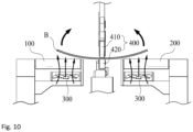
- FIGS. 9 and 10 are diagrams illustrating a second use aspect of the transfer apparatus according to the embodiment of the present invention.
- the second use aspect of the transfer apparatus according the present invention may be configured to just transfer the object B to be transferred.
- the object B to be transferred may be held on the tops of the first transfer module 100 and the second transfer module 200 of the transfer apparatus.
- the upper transfer unit 410 of the third transfer module 400 moves downward and the lower transfer unit 420 moves upward to contact the object B to be transferred between the upper transfer unit 410 and the lower transfer unit 420.
- the belts of the upper transfer unit 410 and the lower transfer unit 420 rotate to provide power to transfer the object B to be transferred.
- the third transfer module 400 completely takes charge of transferring the object B to be transferred and the first transfer module 100 and the second transfer module 200 may not transmit the transfer power to the object B to be transferred.
- the blowing module 300 may cause the air to flow to the top.
- the blowing module 300 causes the air to flow upward, the object B to be transferred is pushed upward by receiving resistance and since the center of the object B to be transferred is fixed between the third transfer modules 400, only both sides of the object B to be transferred may be pushed upward.
- both sides of the object B to be transferred are spaced apart from the first transfer module 100 and the second transfer module 200 not to contact each other.
- each of the first transfer module 100 and the second transfer module 200 moves outside in the transverse direction to advantageously increase a distance between the first transfer module 100 and the second transfer module 200.
- the surface of the roller or the belt is abraded, and as a result, the roller or the belt needs to be periodically replaced and abrasion of the first transfer module 100 and the second transfer module 200 is reduced through such a process to reduce management and maintenance cost of the transfer apparatus.
- the third transfer module 400 has a relatively smaller width than the first transfer module 100 and the second transfer module 200, and thus cost required for replacing the belt is small.
- the third transfer module 400 is used in the course of just transferring the object B to be transferred, and thereby reduce cost required for transferring the management and maintenance of the transfer apparatus simultaneously with transferring the object B to be transferred.
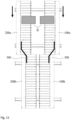
- FIGS. 11 to 13 are diagrams illustrating a third use aspect of the transfer apparatus according to the exemplary embodiment of the present invention.
- the third use aspect of the transfer apparatus relates to a component that transfers and collect a plurality of objects B to be transferred and in the present use aspect, a plurality of transfer apparatuses may be configured to be connected to each other in series.
- the transfer apparatus provided at the front end among the plurality of transfer apparatuses connected in series includes the first transfer module 100a and the second transfer module 200a and the transfer apparatus provided at the rear end may include the first transfer module 100b and the second transfer module 200b.
- the object B to be transferred may be held on the top of the transfer apparatus provided at the front end among the plurality of transfer apparatuses according to the present invention, which are connected in series.
- each of the first transfer module 100a and the second transfer module 200a of the transfer apparatus provided at a front end moves outside in the transverse direction, and as a result, an interval between the first transfer module 100a and the second transfer module 200a may increase.
- Separate objects B to be transferred may be disposed while being provided on the tops of the first transfer module 100a and the second transfer module 200a, respectively.
- first speed and the second speed of the first transfer module 100a and the second transfer module 200a are set to be the same as each other, and as a result, the objects B to be transferred, which are disposed in the first transfer module 100a and the second transfer module 200a, respectively may be transferred at the same speed.
- the blowing module 300 provided in the first transfer module 100a and the second transfer module 200a causes the air to flow downward to advantageously stably fix and transfer the objects B to be transferred, which are disposed in the first transfer module 100a and the second transfer module 200a, respectively.
- first transfer module 100a and the second transfer module 200a are spaced apart from each other, the objects B to be transferred, which are disposed in the first transfer module 100a and the second transfer module 200a, respectively may be disposed to protrude between the first transfer module 100a and the second transfer module 200a.
- Processing of modifying the object B to be transferred may be performed and an operation such as applying a bonding agent for bonding both objects B to be transferred, or the like may be performed.
- first transfer module 100a and the second transfer module 200a are disposed while being spaced apart from each other, various devices required for such a process may be provided in a space between the first transfer module 100a and the second transfer module 200a.
- first transfer module 100a and the second transfer module 200a are configured to separately move in the transverse direction to secure a space required for processing the object B to be transferred.
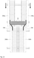
- the object B to be transferred which is processed during such a transfer process, may be transferred from the transfer apparatus provided at the front end to the transfer apparatus provided at the rear end as shown in the FIG 12 .
- both objects B to be transferred may contact each other by a need of bonding both objects B to be transferred to each other, or the like.
- the transfer apparatus may advantageously further include a guide module 500 of which the width decreases in a direction in which the object B to be transferred is transferred.
- the shape and the configuration of the guide module 500 are not limited to the exemplary embodiment, but may be diversified.
- the objects B to be transferred may be transferred while being close to each other by the guide module 500.
- a component that lifts up one-side object B to be transferred may be further included.
- the component used for processing the object B to be transferred may adopt a component which is generally used and if the component is provided for various processing of the object B to be transferred, the component may be diversified without a limit.
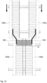
- the objects B to be transferred which contact each other during such a process may be transferred through the first transfer module 100b and the second transfer module 200b as illustrated in FIG. 13 .
- the first transfer module 100b and the second transfer module 200b are disposed to be close to each other to advantageously transfer the object B to be transferred more stably.
- the object B to be transferred may be transferred by using the third transfer module of the transfer apparatus provided at the rear end without using the configurations of the first transfer module 100b and the second transfer module 200b.
- the plurality of objects B to be transferred are transferred and processing the objects B to be transferred is performed by using the transfer apparatus according to the present invention.
- the objects to be transferred are transferred and various types of objects to be transferred are transferred, processed, or rotated by various methods by using the transfer apparatus according to the present invention, that is, the transfer apparatus may be universally used.
- the use aspect is not limited to the exemplary embodiment and if the use aspect includes the configurations in which the first transfer module 100 and the second transfer module 200 of the transfer apparatus according to the present invention may move in the transverse direction, the blowing module 300 influences the objects to be transferred, which are disposed on the tops of the first and second transfer modules 100 and 200, and the third transfer module 400 that has the relatively smaller width to selectively transfer the object B to be transferred, and the like, the use aspect may be variously applied.
Landscapes
- Engineering & Computer Science (AREA)
- Mechanical Engineering (AREA)
- Physics & Mathematics (AREA)
- Fluid Mechanics (AREA)
- Decoration By Transfer Pictures (AREA)
- Intermediate Stations On Conveyors (AREA)
Claims (8)
- Beförderungsvorrichtung, die Folgendes umfasst:ein erstes Beförderungsmodul (100), das konfiguriert ist, einen zu befördernden Gegenstand (B) auf seiner Oberseite zu halten und den zu befördernden Gegenstand (B) mit einer ersten Geschwindigkeit in einer Längsrichtung zu befördern;ein zweites Beförderungsmodul (200), das parallel zum ersten Beförderungsmodul (100) angeordnet ist und konfiguriert ist, den zu befördernden Gegenstand (B) auf seiner Oberseite zu halten und den zu befördernden Gegenstand (B) mit einer zweiten Geschwindigkeit in der Längsrichtung zu befördern; undein Blasmodul (300) unter dem ersten Beförderungsmodul (100) und/oder dem zweiten Beförderungsmodul (200) zum Bewirken, dass Luft nach oben oder nach unten strömt;dadurch gekennzeichnet, dass die Beförderungsvorrichtung ferner Folgendes umfasst:ein drittes Beförderungsmodul (400), das parallel zum ersten Beförderungsmodul (100) und zum zweiten Beförderungsmodul (200) angeordnet ist und konfiguriert ist, den zu befördernden Gegenstand in der Längsrichtung zu befördern,wobei das dritte Beförderungsmodul (400) zwischen dem ersten Beförderungsmodul (100) und dem zweiten Beförderungsmodul (200) vorgesehen ist, undwobei das dritte Beförderungsmodul (400) Folgendes enthält:eine untere Beförderungseinheit (420) zum Befördern des zu befördernden Gegenstands (B) durch Berühren der Unterseite des zu befördernden Gegenstands (B), undeine obere Beförderungseinheit (410) zum Befördern des zu befördernden Gegenstands (B) durch Berühren der Oberseite des zu befördernden Gegenstands (B).
- Beförderungsvorrichtung nach Anspruch 1, wobei das Blasmodul (300) konfiguriert ist zu bewirken, dass die Luft nach unten strömt, während das erste Beförderungsmodul (100) und/oder das zweite Beförderungsmodul (200) den zu befördernden Gegenstand (B) befördern.
- Beförderungsvorrichtung nach Anspruch 1, wobei das erste Beförderungsmodul (100) und das zweite Beförderungsmodul (200) derart ausgebildet sind, dass sie sich in einer querverlaufenden Richtung bewegen.
- Beförderungsvorrichtung nach Anspruch 1, wobei die erste Geschwindigkeit und die zweite Geschwindigkeit des ersten Beförderungsmoduls (100) und des zweiten Beförderungsmoduls (200) derart eingestellt sind, dass sie voneinander verschieden sind.
- Beförderungsvorrichtung nach Anspruch 1, wobei das dritte Beförderungsmodul (400) eine relativ kleinere Breite als das erste Beförderungsmodul (100) und das zweite Beförderungsmodul (200) aufweist.
- Beförderungsvorrichtung nach Anspruch 1, wobei die untere Beförderungseinheit (420) und die obere Beförderungseinheit (410) derart ausgebildet sind, dass sie sich nach oben/nach unten bewegen, derart, dass sie wahlweise den zu befördernden Gegenstand (B) berühren.
- Beförderungsvorrichtung nach Anspruch 1, wobei das Blasmodul (300) konfiguriert ist zu bewirken, dass die Luft nach oben strömt, während das dritte Beförderungsmodul (400) den zu befördernden Gegenstand (B) befördert.
- Beförderungsvorrichtung nach Anspruch 1, die ferner ein Führungsmodul (500) umfasst, dessen Breite in einer Richtung, in der der zu befördernde Gegenstand (B) befördert wird, abnimmt, derart, dass die zu befördernden Gegenstände (B), die das erste und das zweite Beförderungsmodul (100, 200) befördern, einander berühren.
Applications Claiming Priority (1)
| Application Number | Priority Date | Filing Date | Title |
|---|---|---|---|
| PCT/KR2016/007035 WO2018004034A1 (ko) | 2016-06-30 | 2016-06-30 | 이송장치 |
Publications (3)
| Publication Number | Publication Date |
|---|---|
| EP3480143A1 EP3480143A1 (de) | 2019-05-08 |
| EP3480143A4 EP3480143A4 (de) | 2020-02-26 |
| EP3480143B1 true EP3480143B1 (de) | 2024-11-27 |
Family
ID=60786073
Family Applications (1)
| Application Number | Title | Priority Date | Filing Date |
|---|---|---|---|
| EP16907399.6A Active EP3480143B1 (de) | 2016-06-30 | 2016-06-30 | Transportvorrichtung |
Country Status (4)
| Country | Link |
|---|---|
| US (1) | US10179707B2 (de) |
| EP (1) | EP3480143B1 (de) |
| PL (1) | PL3480143T3 (de) |
| WO (1) | WO2018004034A1 (de) |
Families Citing this family (8)
| Publication number | Priority date | Publication date | Assignee | Title |
|---|---|---|---|---|
| EP3251764B1 (de) * | 2016-05-31 | 2019-07-03 | Primetals Technologies Austria GmbH | Verfahren und vorrichtung zur stabilisierung einer bewegung eines gewalzten metallischen bandes auf einem rollgang |
| TWD196943S (zh) * | 2017-11-08 | 2019-04-11 | 香港商蔚來汽車有限公司 | 換電車輛 |
| TWD196783S (zh) * | 2017-11-08 | 2019-04-01 | 香港商蔚來汽車有限公司 | 換電平台 |
| USD921732S1 (en) * | 2017-11-08 | 2021-06-08 | Nio (Anhui) Holding Co., Ltd. | Battery swapping platform |
| CN112340118A (zh) * | 2020-11-18 | 2021-02-09 | 平江县华文食品有限公司 | 整理装置及包装设备 |
| DE102022116481A1 (de) | 2022-07-01 | 2024-01-04 | Deutsche Post Ag | Vorrichtung zum Ausrichten von Objekten |
| DE102022116479A1 (de) | 2022-07-01 | 2024-01-04 | Deutsche Post Ag | Vorrichtung zum Ausrichten von Objekten |
| DE102022116484A1 (de) | 2022-07-01 | 2024-01-04 | Deutsche Post Ag | Vorrichtung zum Ausrichten von Objekten |
Family Cites Families (26)
| Publication number | Priority date | Publication date | Assignee | Title |
|---|---|---|---|---|
| US2895593A (en) * | 1955-06-09 | 1959-07-21 | Rapids Standard Co Inc | Conveyors |
| CH673830A5 (de) * | 1986-02-12 | 1990-04-12 | Will E C H Gmbh & Co | |
| DE4012948A1 (de) * | 1990-04-24 | 1991-10-31 | Roland Man Druckmasch | Vorrichtung zum foerdern von druckbogen |
| JPH08324786A (ja) | 1995-05-31 | 1996-12-10 | Central Glass Co Ltd | 板状体の搬送装置 |
| CH691298A8 (fr) * | 1997-05-30 | 2001-09-14 | Bobst Sa | DISPOSITIF TRANSPORTEUR à BANDE POUR ARTICLES OU EN PLAQUES DE FAIBLE MASSE SPèCIFIQUE. |
| US6216848B1 (en) * | 1999-04-09 | 2001-04-17 | Profold, Inc. | Vacuum table conveying apparatus and associated methods |
| US6471044B1 (en) * | 1999-04-30 | 2002-10-29 | Siemens Electrocom, L.P. | Hold and release singulator |
| TWI327128B (en) | 2003-07-08 | 2010-07-11 | Daifuku Kk | Plate-shaped work piece transporting apparatus |
| KR200339636Y1 (ko) | 2003-10-20 | 2004-01-24 | 주식회사 신성이엔지 | 평판자재의 공기부상 이송장치 |
| EP1666386B1 (de) | 2004-12-03 | 2009-01-14 | Bobst S.A. | Vorrichtung und Verfahren zum Ausrichten von flachen Gegenständen |
| JP4413789B2 (ja) * | 2005-01-24 | 2010-02-10 | 東京エレクトロン株式会社 | ステージ装置および塗布処理装置 |
| JP4553376B2 (ja) * | 2005-07-19 | 2010-09-29 | 東京エレクトロン株式会社 | 浮上式基板搬送処理装置及び浮上式基板搬送処理方法 |
| KR100768086B1 (ko) | 2005-12-08 | 2007-10-18 | 한국전자통신연구원 | 이송물 분류장치 및 분류방법 |
| JP4344755B2 (ja) * | 2007-04-09 | 2009-10-14 | 株式会社日本設計工業 | 薄板状材料搬送用ローラユニット及び薄板状材料搬送装置 |
| DE102007054822A1 (de) * | 2007-11-16 | 2009-05-20 | Heidelberger Druckmaschinen Ag | Vorrichtung zum Drehen flacher Gegenstände, insbesondere von Faltschachtelzuschnitten |
| JP2009161342A (ja) * | 2008-01-10 | 2009-07-23 | Seiko I Infotech Inc | 搬送体及び搬送装置 |
| DE102009025588B4 (de) * | 2008-07-11 | 2022-02-24 | Heidelberger Druckmaschinen Ag | Vorrichtung zum Zuführen und Ausrichten von Bogen, die einer Verarbeitungsmaschine, insbesondere Druckmaschine zugeführt werden |
| JP5372465B2 (ja) | 2008-10-23 | 2013-12-18 | レンゴー株式会社 | 整列搬送装置 |
| KR101033159B1 (ko) * | 2008-11-24 | 2011-05-11 | (주)둔포기계 | 수평형 기판 이송장치 |
| DE102009031516B4 (de) * | 2009-07-02 | 2013-09-05 | Multivac Sepp Haggenmüller Gmbh & Co. Kg | Verfahren zum Gruppieren von Packungen |
| JP5423366B2 (ja) * | 2009-12-08 | 2014-02-19 | 富士ゼロックス株式会社 | シート材搬送装置、画像形成装置 |
| KR20130131526A (ko) | 2012-05-24 | 2013-12-04 | 에이스기계 주식회사 | 판상 요소를 선회시키기 위한 점접촉 방식의 컨베이어 장치 |
| US9708132B2 (en) * | 2013-08-26 | 2017-07-18 | Bobst Mex Sa | Method and device for conveying flat objects |
| US9073704B2 (en) * | 2013-09-09 | 2015-07-07 | Laitram, L.L.C. | Conveyor employing a vacuum |
| KR101507905B1 (ko) | 2014-02-21 | 2015-04-07 | 에이스기계 주식회사 | 블랭크 이송 가공 장치 |
| CN104536171B (zh) * | 2015-01-13 | 2017-04-12 | 京东方科技集团股份有限公司 | 一种液晶屏检测装置 |
-
2016
- 2016-06-30 EP EP16907399.6A patent/EP3480143B1/de active Active
- 2016-06-30 US US15/314,940 patent/US10179707B2/en active Active
- 2016-06-30 WO PCT/KR2016/007035 patent/WO2018004034A1/ko not_active Ceased
- 2016-06-30 PL PL16907399.6T patent/PL3480143T3/pl unknown
Also Published As
| Publication number | Publication date |
|---|---|
| US10179707B2 (en) | 2019-01-15 |
| PL3480143T3 (pl) | 2025-03-17 |
| WO2018004034A1 (ko) | 2018-01-04 |
| EP3480143A4 (de) | 2020-02-26 |
| EP3480143A1 (de) | 2019-05-08 |
| US20180215556A1 (en) | 2018-08-02 |
Similar Documents
| Publication | Publication Date | Title |
|---|---|---|
| EP3480143B1 (de) | Transportvorrichtung | |
| KR20170036303A (ko) | 컨베이어의 방향전환장치 | |
| CN103419794A (zh) | 物品输送设备 | |
| KR20180014679A (ko) | 방향전환장치를 갖는 컨베이어 | |
| KR101201702B1 (ko) | 가이드 롤러 장치 | |
| CN205771894U (zh) | 一种滚轮输送装置 | |
| KR20120114113A (ko) | 롤러체인 컨베이어 | |
| CN106144510A (zh) | 供料机构及包含供料机构的柔性生产线 | |
| CN103183225A (zh) | 用于物品输送线的物品自动对中装置和物品输送线 | |
| CN103316806A (zh) | 一种自动涂胶装置 | |
| KR101364744B1 (ko) | 웨이퍼 반송장치 | |
| JP6892441B2 (ja) | 品物を移送するための移送システム | |
| CN204340407U (zh) | 一种智能卡平印清洁装置 | |
| CN204980518U (zh) | 复漂机上的传送装置 | |
| KR20180003035A (ko) | 이송장치 | |
| US976540A (en) | Device for feeding bottles to corking-machines. | |
| KR101451619B1 (ko) | 무접점으로 소재를 연속 양면 코팅하는 장치 | |
| US9227335B2 (en) | System and method for cutting tubular shrink sleeve material for application to containers | |
| CN108797300B (zh) | 一种大型运输船舶用划线机 | |
| CN105381923A (zh) | 门板涂漆装置 | |
| KR102249428B1 (ko) | 용기 분할 이송장치 | |
| US20160083193A1 (en) | Device and method for depalletization | |
| CN104003105A (zh) | 带式输送机自动纠偏系统 | |
| CN105990191A (zh) | 基板输送托台、划线装置以及输送基板的方法 | |
| KR101833457B1 (ko) | 반송 속도 개별 제어형 컨베이어 장치 및 컨베이어 장치의 반송 속도 개별 제어 방법 |
Legal Events
| Date | Code | Title | Description |
|---|---|---|---|
| STAA | Information on the status of an ep patent application or granted ep patent |
Free format text: STATUS: THE INTERNATIONAL PUBLICATION HAS BEEN MADE |
|
| PUAI | Public reference made under article 153(3) epc to a published international application that has entered the european phase |
Free format text: ORIGINAL CODE: 0009012 |
|
| STAA | Information on the status of an ep patent application or granted ep patent |
Free format text: STATUS: REQUEST FOR EXAMINATION WAS MADE |
|
| 17P | Request for examination filed |
Effective date: 20180829 |
|
| AK | Designated contracting states |
Kind code of ref document: A1 Designated state(s): AL AT BE BG CH CY CZ DE DK EE ES FI FR GB GR HR HU IE IS IT LI LT LU LV MC MK MT NL NO PL PT RO RS SE SI SK SM TR |
|
| AX | Request for extension of the european patent |
Extension state: BA ME |
|
| DAV | Request for validation of the european patent (deleted) | ||
| DAX | Request for extension of the european patent (deleted) | ||
| A4 | Supplementary search report drawn up and despatched |
Effective date: 20200128 |
|
| RIC1 | Information provided on ipc code assigned before grant |
Ipc: B65G 21/10 20060101ALI20200122BHEP Ipc: B65G 51/02 20060101ALI20200122BHEP Ipc: B65G 13/11 20060101ALI20200122BHEP Ipc: B65G 37/00 20060101AFI20200122BHEP Ipc: B65G 47/244 20060101ALI20200122BHEP Ipc: B65G 21/20 20060101ALI20200122BHEP |
|
| STAA | Information on the status of an ep patent application or granted ep patent |
Free format text: STATUS: EXAMINATION IS IN PROGRESS |
|
| 17Q | First examination report despatched |
Effective date: 20210813 |
|
| GRAP | Despatch of communication of intention to grant a patent |
Free format text: ORIGINAL CODE: EPIDOSNIGR1 |
|
| STAA | Information on the status of an ep patent application or granted ep patent |
Free format text: STATUS: GRANT OF PATENT IS INTENDED |
|
| INTG | Intention to grant announced |
Effective date: 20240705 |
|
| GRAS | Grant fee paid |
Free format text: ORIGINAL CODE: EPIDOSNIGR3 |
|
| GRAA | (expected) grant |
Free format text: ORIGINAL CODE: 0009210 |
|
| STAA | Information on the status of an ep patent application or granted ep patent |
Free format text: STATUS: THE PATENT HAS BEEN GRANTED |
|
| AK | Designated contracting states |
Kind code of ref document: B1 Designated state(s): AL AT BE BG CH CY CZ DE DK EE ES FI FR GB GR HR HU IE IS IT LI LT LU LV MC MK MT NL NO PL PT RO RS SE SI SK SM TR |
|
| REG | Reference to a national code |
Ref country code: GB Ref legal event code: FG4D |
|
| REG | Reference to a national code |
Ref country code: CH Ref legal event code: EP |
|
| REG | Reference to a national code |
Ref country code: IE Ref legal event code: FG4D |
|
| REG | Reference to a national code |
Ref country code: DE Ref legal event code: R096 Ref document number: 602016090448 Country of ref document: DE |
|
| REG | Reference to a national code |
Ref country code: LT Ref legal event code: MG9D |
|
| REG | Reference to a national code |
Ref country code: NL Ref legal event code: MP Effective date: 20241127 |
|
| PG25 | Lapsed in a contracting state [announced via postgrant information from national office to epo] |
Ref country code: HR Free format text: LAPSE BECAUSE OF FAILURE TO SUBMIT A TRANSLATION OF THE DESCRIPTION OR TO PAY THE FEE WITHIN THE PRESCRIBED TIME-LIMIT Effective date: 20241127 Ref country code: PT Free format text: LAPSE BECAUSE OF FAILURE TO SUBMIT A TRANSLATION OF THE DESCRIPTION OR TO PAY THE FEE WITHIN THE PRESCRIBED TIME-LIMIT Effective date: 20250327 Ref country code: IS Free format text: LAPSE BECAUSE OF FAILURE TO SUBMIT A TRANSLATION OF THE DESCRIPTION OR TO PAY THE FEE WITHIN THE PRESCRIBED TIME-LIMIT Effective date: 20250327 |
|
| PG25 | Lapsed in a contracting state [announced via postgrant information from national office to epo] |
Ref country code: FI Free format text: LAPSE BECAUSE OF FAILURE TO SUBMIT A TRANSLATION OF THE DESCRIPTION OR TO PAY THE FEE WITHIN THE PRESCRIBED TIME-LIMIT Effective date: 20241127 Ref country code: NL Free format text: LAPSE BECAUSE OF FAILURE TO SUBMIT A TRANSLATION OF THE DESCRIPTION OR TO PAY THE FEE WITHIN THE PRESCRIBED TIME-LIMIT Effective date: 20241127 |
|
| REG | Reference to a national code |
Ref country code: AT Ref legal event code: MK05 Ref document number: 1745535 Country of ref document: AT Kind code of ref document: T Effective date: 20241127 |
|
| PG25 | Lapsed in a contracting state [announced via postgrant information from national office to epo] |
Ref country code: BG Free format text: LAPSE BECAUSE OF FAILURE TO SUBMIT A TRANSLATION OF THE DESCRIPTION OR TO PAY THE FEE WITHIN THE PRESCRIBED TIME-LIMIT Effective date: 20241127 |
|
| PG25 | Lapsed in a contracting state [announced via postgrant information from national office to epo] |
Ref country code: ES Free format text: LAPSE BECAUSE OF FAILURE TO SUBMIT A TRANSLATION OF THE DESCRIPTION OR TO PAY THE FEE WITHIN THE PRESCRIBED TIME-LIMIT Effective date: 20241127 |
|
| PG25 | Lapsed in a contracting state [announced via postgrant information from national office to epo] |
Ref country code: NO Free format text: LAPSE BECAUSE OF FAILURE TO SUBMIT A TRANSLATION OF THE DESCRIPTION OR TO PAY THE FEE WITHIN THE PRESCRIBED TIME-LIMIT Effective date: 20250227 |
|
| PG25 | Lapsed in a contracting state [announced via postgrant information from national office to epo] |
Ref country code: LV Free format text: LAPSE BECAUSE OF FAILURE TO SUBMIT A TRANSLATION OF THE DESCRIPTION OR TO PAY THE FEE WITHIN THE PRESCRIBED TIME-LIMIT Effective date: 20241127 Ref country code: GR Free format text: LAPSE BECAUSE OF FAILURE TO SUBMIT A TRANSLATION OF THE DESCRIPTION OR TO PAY THE FEE WITHIN THE PRESCRIBED TIME-LIMIT Effective date: 20250228 Ref country code: AT Free format text: LAPSE BECAUSE OF FAILURE TO SUBMIT A TRANSLATION OF THE DESCRIPTION OR TO PAY THE FEE WITHIN THE PRESCRIBED TIME-LIMIT Effective date: 20241127 |
|
| PG25 | Lapsed in a contracting state [announced via postgrant information from national office to epo] |
Ref country code: RS Free format text: LAPSE BECAUSE OF FAILURE TO SUBMIT A TRANSLATION OF THE DESCRIPTION OR TO PAY THE FEE WITHIN THE PRESCRIBED TIME-LIMIT Effective date: 20250227 |
|
| PG25 | Lapsed in a contracting state [announced via postgrant information from national office to epo] |
Ref country code: SM Free format text: LAPSE BECAUSE OF FAILURE TO SUBMIT A TRANSLATION OF THE DESCRIPTION OR TO PAY THE FEE WITHIN THE PRESCRIBED TIME-LIMIT Effective date: 20241127 |
|
| PGFP | Annual fee paid to national office [announced via postgrant information from national office to epo] |
Ref country code: PL Payment date: 20250617 Year of fee payment: 10 Ref country code: DE Payment date: 20250626 Year of fee payment: 10 |
|
| PG25 | Lapsed in a contracting state [announced via postgrant information from national office to epo] |
Ref country code: DK Free format text: LAPSE BECAUSE OF FAILURE TO SUBMIT A TRANSLATION OF THE DESCRIPTION OR TO PAY THE FEE WITHIN THE PRESCRIBED TIME-LIMIT Effective date: 20241127 |
|
| PGFP | Annual fee paid to national office [announced via postgrant information from national office to epo] |
Ref country code: GB Payment date: 20250620 Year of fee payment: 10 |
|
| PG25 | Lapsed in a contracting state [announced via postgrant information from national office to epo] |
Ref country code: EE Free format text: LAPSE BECAUSE OF FAILURE TO SUBMIT A TRANSLATION OF THE DESCRIPTION OR TO PAY THE FEE WITHIN THE PRESCRIBED TIME-LIMIT Effective date: 20241127 |
|
| PG25 | Lapsed in a contracting state [announced via postgrant information from national office to epo] |
Ref country code: RO Free format text: LAPSE BECAUSE OF FAILURE TO SUBMIT A TRANSLATION OF THE DESCRIPTION OR TO PAY THE FEE WITHIN THE PRESCRIBED TIME-LIMIT Effective date: 20241127 |
|
| PG25 | Lapsed in a contracting state [announced via postgrant information from national office to epo] |
Ref country code: SK Free format text: LAPSE BECAUSE OF FAILURE TO SUBMIT A TRANSLATION OF THE DESCRIPTION OR TO PAY THE FEE WITHIN THE PRESCRIBED TIME-LIMIT Effective date: 20241127 |
|
| PG25 | Lapsed in a contracting state [announced via postgrant information from national office to epo] |
Ref country code: CZ Free format text: LAPSE BECAUSE OF FAILURE TO SUBMIT A TRANSLATION OF THE DESCRIPTION OR TO PAY THE FEE WITHIN THE PRESCRIBED TIME-LIMIT Effective date: 20241127 |
|
| PG25 | Lapsed in a contracting state [announced via postgrant information from national office to epo] |
Ref country code: IT Free format text: LAPSE BECAUSE OF FAILURE TO SUBMIT A TRANSLATION OF THE DESCRIPTION OR TO PAY THE FEE WITHIN THE PRESCRIBED TIME-LIMIT Effective date: 20241127 |
|
| REG | Reference to a national code |
Ref country code: DE Ref legal event code: R097 Ref document number: 602016090448 Country of ref document: DE |
|
| PG25 | Lapsed in a contracting state [announced via postgrant information from national office to epo] |
Ref country code: SE Free format text: LAPSE BECAUSE OF FAILURE TO SUBMIT A TRANSLATION OF THE DESCRIPTION OR TO PAY THE FEE WITHIN THE PRESCRIBED TIME-LIMIT Effective date: 20241127 |
|
| PLBE | No opposition filed within time limit |
Free format text: ORIGINAL CODE: 0009261 |
|
| STAA | Information on the status of an ep patent application or granted ep patent |
Free format text: STATUS: NO OPPOSITION FILED WITHIN TIME LIMIT |
|
| 26N | No opposition filed |
Effective date: 20250828 |