EP3479977B1 - Verfahren zur herstellung von wandbauteilen für gebäude - Google Patents
Verfahren zur herstellung von wandbauteilen für gebäude Download PDFInfo
- Publication number
- EP3479977B1 EP3479977B1 EP18204556.7A EP18204556A EP3479977B1 EP 3479977 B1 EP3479977 B1 EP 3479977B1 EP 18204556 A EP18204556 A EP 18204556A EP 3479977 B1 EP3479977 B1 EP 3479977B1
- Authority
- EP
- European Patent Office
- Prior art keywords
- panels
- laminated timber
- cross laminated
- boards
- transversely
- Prior art date
- Legal status (The legal status is an assumption and is not a legal conclusion. Google has not performed a legal analysis and makes no representation as to the accuracy of the status listed.)
- Active
Links
- 238000004519 manufacturing process Methods 0.000 title claims description 16
- 238000000034 method Methods 0.000 claims description 28
- 238000004026 adhesive bonding Methods 0.000 claims description 5
- 238000003860 storage Methods 0.000 description 7
- 229910000831 Steel Inorganic materials 0.000 description 5
- 239000010959 steel Substances 0.000 description 5
- 238000005520 cutting process Methods 0.000 description 4
- 239000007787 solid Substances 0.000 description 4
- 239000002023 wood Substances 0.000 description 4
- 238000010276 construction Methods 0.000 description 3
- 239000007858 starting material Substances 0.000 description 3
- 239000002699 waste material Substances 0.000 description 3
- 238000009776 industrial production Methods 0.000 description 2
- 238000005304 joining Methods 0.000 description 2
- 239000002184 metal Substances 0.000 description 2
- 239000000969 carrier Substances 0.000 description 1
- 238000010924 continuous production Methods 0.000 description 1
- 238000007796 conventional method Methods 0.000 description 1
- 238000011031 large-scale manufacturing process Methods 0.000 description 1
- 239000000463 material Substances 0.000 description 1
- 238000003801 milling Methods 0.000 description 1
- 230000000644 propagated effect Effects 0.000 description 1
Images

Classifications
-
- B—PERFORMING OPERATIONS; TRANSPORTING
- B27—WORKING OR PRESERVING WOOD OR SIMILAR MATERIAL; NAILING OR STAPLING MACHINES IN GENERAL
- B27M—WORKING OF WOOD NOT PROVIDED FOR IN SUBCLASSES B27B - B27L; MANUFACTURE OF SPECIFIC WOODEN ARTICLES
- B27M1/00—Working of wood not provided for in subclasses B27B - B27L, e.g. by stretching
- B27M1/08—Working of wood not provided for in subclasses B27B - B27L, e.g. by stretching by multi-step processes
-
- E—FIXED CONSTRUCTIONS
- E04—BUILDING
- E04B—GENERAL BUILDING CONSTRUCTIONS; WALLS, e.g. PARTITIONS; ROOFS; FLOORS; CEILINGS; INSULATION OR OTHER PROTECTION OF BUILDINGS
- E04B2/00—Walls, e.g. partitions, for buildings; Wall construction with regard to insulation; Connections specially adapted to walls
- E04B2/56—Load-bearing walls of framework or pillarwork; Walls incorporating load-bearing elongated members
- E04B2/70—Load-bearing walls of framework or pillarwork; Walls incorporating load-bearing elongated members with elongated members of wood
-
- B—PERFORMING OPERATIONS; TRANSPORTING
- B27—WORKING OR PRESERVING WOOD OR SIMILAR MATERIAL; NAILING OR STAPLING MACHINES IN GENERAL
- B27B—SAWS FOR WOOD OR SIMILAR MATERIAL; COMPONENTS OR ACCESSORIES THEREFOR
- B27B5/00—Sawing machines working with circular or cylindrical saw blades; Components or equipment therefor
- B27B5/02—Sawing machines working with circular or cylindrical saw blades; Components or equipment therefor characterised by a special purpose only
- B27B5/06—Sawing machines working with circular or cylindrical saw blades; Components or equipment therefor characterised by a special purpose only for dividing plates in parts of determined size, e.g. panels
-
- B—PERFORMING OPERATIONS; TRANSPORTING
- B27—WORKING OR PRESERVING WOOD OR SIMILAR MATERIAL; NAILING OR STAPLING MACHINES IN GENERAL
- B27M—WORKING OF WOOD NOT PROVIDED FOR IN SUBCLASSES B27B - B27L; MANUFACTURE OF SPECIFIC WOODEN ARTICLES
- B27M3/00—Manufacture or reconditioning of specific semi-finished or finished articles
- B27M3/0013—Manufacture or reconditioning of specific semi-finished or finished articles of composite or compound articles
- B27M3/0026—Manufacture or reconditioning of specific semi-finished or finished articles of composite or compound articles characterised by oblong elements connected laterally
-
- B—PERFORMING OPERATIONS; TRANSPORTING
- B65—CONVEYING; PACKING; STORING; HANDLING THIN OR FILAMENTARY MATERIAL
- B65D—CONTAINERS FOR STORAGE OR TRANSPORT OF ARTICLES OR MATERIALS, e.g. BAGS, BARRELS, BOTTLES, BOXES, CANS, CARTONS, CRATES, DRUMS, JARS, TANKS, HOPPERS, FORWARDING CONTAINERS; ACCESSORIES, CLOSURES, OR FITTINGS THEREFOR; PACKAGING ELEMENTS; PACKAGES
- B65D9/00—Containers having bodies formed by interconnecting or uniting two or more rigid, or substantially rigid, components made wholly or mainly of wood or substitutes therefor
- B65D9/32—Details of wooden walls; Connections between walls
- B65D9/34—Joints; Local reinforcements
-
- E—FIXED CONSTRUCTIONS
- E04—BUILDING
- E04B—GENERAL BUILDING CONSTRUCTIONS; WALLS, e.g. PARTITIONS; ROOFS; FLOORS; CEILINGS; INSULATION OR OTHER PROTECTION OF BUILDINGS
- E04B1/00—Constructions in general; Structures which are not restricted either to walls, e.g. partitions, or floors or ceilings or roofs
- E04B1/02—Structures consisting primarily of load-supporting, block-shaped, or slab-shaped elements
- E04B1/10—Structures consisting primarily of load-supporting, block-shaped, or slab-shaped elements the elements consisting of wood
-
- E—FIXED CONSTRUCTIONS
- E04—BUILDING
- E04B—GENERAL BUILDING CONSTRUCTIONS; WALLS, e.g. PARTITIONS; ROOFS; FLOORS; CEILINGS; INSULATION OR OTHER PROTECTION OF BUILDINGS
- E04B1/00—Constructions in general; Structures which are not restricted either to walls, e.g. partitions, or floors or ceilings or roofs
- E04B1/348—Structures composed of units comprising at least considerable parts of two sides of a room, e.g. box-like or cell-like units closed or in skeleton form
- E04B1/34815—Elements not integrated in a skeleton
- E04B1/34838—Elements not integrated in a skeleton the supporting structure consisting of wood
-
- E—FIXED CONSTRUCTIONS
- E04—BUILDING
- E04B—GENERAL BUILDING CONSTRUCTIONS; WALLS, e.g. PARTITIONS; ROOFS; FLOORS; CEILINGS; INSULATION OR OTHER PROTECTION OF BUILDINGS
- E04B1/00—Constructions in general; Structures which are not restricted either to walls, e.g. partitions, or floors or ceilings or roofs
- E04B1/348—Structures composed of units comprising at least considerable parts of two sides of a room, e.g. box-like or cell-like units closed or in skeleton form
- E04B1/34869—Elements for special technical purposes, e.g. with a sanitary equipment
-
- E—FIXED CONSTRUCTIONS
- E04—BUILDING
- E04C—STRUCTURAL ELEMENTS; BUILDING MATERIALS
- E04C2/00—Building elements of relatively thin form for the construction of parts of buildings, e.g. sheet materials, slabs, or panels
- E04C2/02—Building elements of relatively thin form for the construction of parts of buildings, e.g. sheet materials, slabs, or panels characterised by specified materials
- E04C2/10—Building elements of relatively thin form for the construction of parts of buildings, e.g. sheet materials, slabs, or panels characterised by specified materials of wood, fibres, chips, vegetable stems, or the like; of plastics; of foamed products
- E04C2/12—Building elements of relatively thin form for the construction of parts of buildings, e.g. sheet materials, slabs, or panels characterised by specified materials of wood, fibres, chips, vegetable stems, or the like; of plastics; of foamed products of solid wood
-
- E—FIXED CONSTRUCTIONS
- E04—BUILDING
- E04C—STRUCTURAL ELEMENTS; BUILDING MATERIALS
- E04C2/00—Building elements of relatively thin form for the construction of parts of buildings, e.g. sheet materials, slabs, or panels
- E04C2/02—Building elements of relatively thin form for the construction of parts of buildings, e.g. sheet materials, slabs, or panels characterised by specified materials
- E04C2/10—Building elements of relatively thin form for the construction of parts of buildings, e.g. sheet materials, slabs, or panels characterised by specified materials of wood, fibres, chips, vegetable stems, or the like; of plastics; of foamed products
- E04C2/24—Building elements of relatively thin form for the construction of parts of buildings, e.g. sheet materials, slabs, or panels characterised by specified materials of wood, fibres, chips, vegetable stems, or the like; of plastics; of foamed products laminated and composed of materials covered by two or more of groups E04C2/12, E04C2/16, E04C2/20
-
- E—FIXED CONSTRUCTIONS
- E04—BUILDING
- E04C—STRUCTURAL ELEMENTS; BUILDING MATERIALS
- E04C2/00—Building elements of relatively thin form for the construction of parts of buildings, e.g. sheet materials, slabs, or panels
- E04C2/44—Building elements of relatively thin form for the construction of parts of buildings, e.g. sheet materials, slabs, or panels characterised by the purpose
- E04C2/46—Building elements of relatively thin form for the construction of parts of buildings, e.g. sheet materials, slabs, or panels characterised by the purpose specially adapted for making walls
-
- E—FIXED CONSTRUCTIONS
- E04—BUILDING
- E04B—GENERAL BUILDING CONSTRUCTIONS; WALLS, e.g. PARTITIONS; ROOFS; FLOORS; CEILINGS; INSULATION OR OTHER PROTECTION OF BUILDINGS
- E04B2103/00—Material constitution of slabs, sheets or the like
- E04B2103/04—Material constitution of slabs, sheets or the like of plastics, fibrous material or wood
Definitions
- the present invention relates to a method for manufacturing wall components for buildings.
- the industrial production of large wall components typically includes the connection of several smaller panels along common longitudinal sides. If window or door openings are to be worked into the wall components, these are usually cut out or milled out.
- GB 936 135 A discloses a continuous process for gluing a plurality of boards along their longitudinal sides, the boards being glued together to form a carpet and then individual panels of a defined width being cut off from the carpet.
- the invention therefore deals with a method for producing wall components for room cells, for example, which overcomes these disadvantages of known methods.
- the invention relates to a method for the production of wall components for buildings, with wooden panels of a certain width and length being kept in a magazine and with the panels being sawed transversely to the longitudinal direction in order to obtain wooden panels of the same width and shorter length, with several panels being placed transversely to the direction of travel on a conveyor track in such a way that the panels are flush on their transverse sides and the longitudinal sides of successive panels touch one another, the panels on the conveyor track along the adjacent longitudinal sides connected to form a first carpet of cross-laminated timber, and the first carpet of cross-laminated timber is sawn transversely to the direction of travel of the conveyor track in order to obtain wooden panels of a defined width.
- the invention is directed to a method for the production of wall components for buildings, in which cross laminated timber panels of a certain width and length are held in a magazine and the panels are sawed transversely to the longitudinal direction to obtain cross laminated timber panels of the same width and shorter length, several panels being placed transversely to the running direction on a conveyor track in such a way that the panels are flush on their transverse sides and the longitudinal sides of successive panels touch one another, the panels on the conveyor track along the lying longitudinal sides are connected to form a first carpet of cross-laminated timber, and the first carpet is sawed transversely to the direction of travel of the conveyor belt in order to obtain cross-laminated timber panels of a defined width.
- the height of the first carpet and the cross laminated timber panels corresponds to the length of the panels.
- the method according to the invention has the advantage that cross-laminated timber panels of any height and width can be produced from simple standard panels in an automated process.
- the method ensures that the possible width of the panels is not limited to a multiple of the width of the panels, but can be freely selected. Furthermore, this results in Handling a gain in precision. Because tolerances in the width of the panels are not passed on to the outer dimensions of the panels. Instead, a determination is made directly in the process using, for example, a precision saw. Dimensional accuracies of +/- 1 mm can be achieved for large panels.
- Wall components manufactured using the method can be used in the finished building, for example, as exterior walls or interior walls.
- the wall components produced using the method can be used as side wall components of a room cell according to the invention. Use as ceilings and/or floors is also conceivable.
- the thicknesses and lengths of the panels are preferably standardized, but do not always have to be the same.
- the panels are between 5 and 20 m long and between 1 and 2.5 m wide.
- Preferred dimensions are 10-16 m long and 1.25 m wide.
- the thickness of the panels can be between 6 and 24 cm.
- Preferred thicknesses are 10, 12 or 14 cm. Panels of these dimensions can be transported in simple trucks without excess length or width. They are easy to make and handle with standard tools. Cross laminated timber panels of these dimensions are available as standard.
- the length of the panels and therefore the height of the first carpet and the panels can be between 3 m and 4 m, for example.
- the intermediate parts can be, for example, intermediate panels made of cross laminated timber, glued laminated timber or solid structural timber.
- the height of such intermediate plates is lower than the height of the large cross-laminated timber panels. If intermediate plates are used, it can preferably be provided that these are inserted into the gaps in such a way that each intermediate plate is flush with the adjacent plates at the top or bottom and/or that the longitudinal sides of the intermediate plates and the adjacent plates touch one another. The panels can then go along the adjacent long sides are connected.
- intermediate carriers made of wood or steel, for example is also conceivable.
- the intermediate parts serve as parapets if they run in the lower part of the panels, for example flush with the lower edge of the panels, or as lintels if they run in the upper part of the panels, for example flush with the top edge of the panels.
- the height or vertical extent of the intermediate parts can be 135 cm, for example.
- the height or vertical extent of the intermediate parts can be 22 cm, for example.
- this manufacturing method Compared to conventional methods of manufacturing wall components with window openings, where the window opening is cut out or milled out of a panel, this manufacturing method has the great advantage that there is almost no waste. This lack of waste leads to significant cost savings in the large-scale production of wall components and increases the overall sustainability of the concept.
- two intermediate parts are inserted into the gap, with an intermediate part being arranged on the upper side of the plate, for example flush with the upper edge and an intermediate part on the underside of the plate, for example flush with the lower edge of the plate.
- Window openings with parapets and lintel can be incorporated into the wall components. The window opening is formed by the remaining portion of the gap between the top of the lower intermediate piece and the underside of the upper intermediate piece.
- the intermediate parts are intermediate plates that are produced by sawing cross laminated timber panels of the magazine transversely to the longitudinal direction in order to obtain short cross laminated timber panels of the same width and with a shorter length compared to the panels, that several short panels transverse to the running direction on a second conveyor track are laid in such a way that the short panels are flush on their transverse sides and the long sides of consecutive short panels touch each other, that the short panels on the second conveyor track are connected along the adjacent longitudinal sides to form a second carpet of cross-laminated timber, and that the second carpet is sawed transversely to the direction of travel of the second conveyor track in order to obtain intermediate panels of a defined width.
- the carpeting process used to produce the large panels is also used to produce intermediate parts in the form of intermediate panels. This has the advantage of low width tolerances and any choice of width.
- the intermediate parts are intermediate plates which are obtained by sawing cross-laminated timber panels of the magazine transversely to the longitudinal direction.
- intermediate plates with a width of, for example, 1.25 m that corresponds to the width of the wooden panels can be easily produced.
- the panels are cross-laminated timber panels, the panels and possibly at least part of the intermediate panels are also made of cross-laminated timber.
- Cross-laminated timber is available in the dimensions mentioned and, for the reasons already mentioned in connection with the room cell, is particularly advantageous for use in the present method, with which wall components for houses and, for example, for such room cells are to be produced.
- intermediate plates or intermediate supports are provided separately, this part of the intermediate plates preferably being intermediate plates or intermediate supports made of glued laminated timber or structural timber or steel.
- connection of the adjacent panels and/or the short panels and/or panels and/or intermediate parts can be achieved by inserting mechanical fasteners or by gluing.
- the elements can be connected by hammering in brackets.
- the elements can be glued. This is preferred because the potential problem of metal parts at positions where the carpet is to be cut does not arise.
- a piece of carpet is to be cut in an unauthorized location, such as in the area of a connecting clip between two panels, it is envisaged that a piece of carpet will be cut off and discarded.
- cut-off end pieces of the first carpet are temporarily stored and then reinserted into the first carpet or a carpet at a later point in time, like a cross-laminated timber panel. For example, changing the desired room height can make it necessary to change the carpet height in the process. It may be necessary to cut off an end piece of the carpet. This is then temporarily stored and used again as a counterpart to a long panel in the carpet at the next opportunity, for example when returning to the original carpet height.
- FIG 1 an exemplary factory layout for carrying out a carpet production method according to the invention for the production of wall components is shown.
- the plant includes an access area for trucks with a magazine 202 arranged directly adjacent to it.
- the magazine 202 includes individual storage areas for pallets with standardized cross-laminated timber panels of specific dimensions. Preferably some or all of the storage areas have the same dimensions to accommodate cross laminated timber panels of the same dimensions. For the most part only cross-laminated timber panels of the same width are required as starting material for the method according to the invention, so that with such a designed Storage optimal space utilization is achieved. Sufficient material can be kept available with limited space. If cross laminated timber panels of different thicknesses are required, these fit into all storage areas regardless of their thickness. Suitable dimensions for the cross laminated timber panels include, for example, 1.25 x 10⁻¹⁶ m. Suitable different panel thicknesses are, for example, 10, 12 or 14 cm.
- the type of panels accommodated in the individual storage areas of the magazine 202 ie their thickness and their type of wood, is communicated individually to an electronic control unit or is preset.
- a crane robot is provided above the magazine 202 in order to be able to lift the length of the panels that are currently required onto a supply track 206 .
- a precision saw 207 is arranged on the supply track 206, with which the panels can be shortened to any length with a maximum error of +/-1 mm.
- a main conveyor track 208 and a secondary conveyor track 209 branch off from the supply track 206 at different branches. Both these tracks 208 and 209 run from the supply track 206 in the same direction.
- a manipulation device can be used to control which of the pieces obtained by sawing up the panels go onto which of the webs 208 and 209 .
- a separate supply track can also be arranged for the secondary conveyor belt 209 next to the existing track 206 including a precision saw.
- only panels 210 of a single length are cut from the panels in the saw 207 and directed onto the main conveyor track 208 flush widthwise. There the panels 210 are pushed together in such a way that their longitudinal edges touch one another.
- a connecting machine 211 the adjacent long sides of the panels 210 are then mechanical Connecting and/or gluing, preferably gluing, to form a wooden carpet 212.
- Another precision saw 213 then saws the carpet 212 perpendicular to the direction of travel of the web 208 to obtain wooden panels which have the same height as the panels 210 and carpet 212, respectively.
- the width of the wooden panels can be freely selected in the saw 213.
- the saw 213 is designed to cut the carpet 212 into wall panels of any width with a maximum error of +/- 1mm.
- shorter pieces 218 are also cut from the panels in the saw 207 and directed onto the secondary conveyor track 209, or alternatively directed onto the secondary conveyor track from the separate supply track described above as an alternative. There the shorter pieces 218 are combined to form a carpet 219 according to the same principle and cut into intermediate panels of any desired length, as is done for the panels 210 on the main conveyor track 208 .
- a connecting machine 221, a precision saw 222 and a waste storage area are also available on the secondary conveyor track 209.
- the secondary conveyor track 209 ends at a transfer track 226, which leads to the main conveyor track 208 and opens into this at a junction point 227.
- Wall panels that have already been cut to size are already present at the joining point 227 .
- a magazine for glued laminated timber beams, or alternatively solid structural timber or steel beams, and a manipulation device are arranged at the joining point 227 .
- the manipulation device includes, in addition to an intervention device for positioning the wall panels, the intermediate panels and the glued laminated timber beams or solid construction timber or steel girders, there is also a connection machine.
- the intermediate plate typically serves as a parapet and the laminated wood support as a lintel.
- the finished wall components then enter a processing area located at the end of the web.
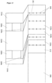
- figure 2 shows the schematic assembly of an exemplary wall in the carpet process.
- the wooden carpet 212 located on the main conveyor track 208 is shown. It consists of individual cross-laminated timber panels 210a, 210b, etc., which all have the same nominal width of 1.25 m and are bonded, for example glued and/or mechanically connected, for example by means of metal clips 240, along the common longitudinal sides.
- the drawing indicates that the widths of the wooden panels 212 have a certain tolerance.
- a wooden panel is only 1249 mm wide, while another wooden panel is 1260 mm wide.
- Tolerances of this magnitude are quite possible with cross-laminated timber panels provided on an industrial scale and a gain in dimensional accuracy would be associated with considerable additional costs.
- tolerances of this kind and possibly added tolerances in the finished wall components for use in a building are within the scope of the invention concept intolerable.
- a significant advantage of the method according to the invention is therefore that these tolerances in the starting material can be compensated for during processing within the scope of the method according to the invention, since the carpet 212 is cut up anyway using the precision saw 213 in such a way that the width of the panels is accurate to the millimeter.
- the cutting lines of the precision saw 213 are marked with the reference number 241 in the figure.
- the cutting lines 241 are such that, among other things, three panels 214a, 214b and 214c with widths of 1470 mm, 2910 mm and 750 mm are cut out of the carpet 212 .
- figure 2 1 shows a completed wall member 230 with two window openings made up of three panels 214a, 214b and 214c associated with the upper portion of FIG figure 2 was explained, as well as two parapets 220a and 220b made of cross laminated timber and two lintels 229a and 229b made of glued laminated timber, each having a width of 1250 mm.
- the parapets can be as related to above figure 1 are described in more detail in the carpet process.
- the falls are related as above figure 1 described in more detail and the use of the parapets and lintels between the panels and their connection to the panels is also as above in connection with figure 1 described in more detail.
Landscapes
- Engineering & Computer Science (AREA)
- Architecture (AREA)
- Life Sciences & Earth Sciences (AREA)
- Wood Science & Technology (AREA)
- Civil Engineering (AREA)
- Structural Engineering (AREA)
- Physics & Mathematics (AREA)
- Electromagnetism (AREA)
- Forests & Forestry (AREA)
- Mechanical Engineering (AREA)
- Health & Medical Sciences (AREA)
- Epidemiology (AREA)
- Public Health (AREA)
- Manufacturing & Machinery (AREA)
- Building Environments (AREA)
Description
- Die vorliegende Erfindung betrifft ein Verfahren zur Herstellung von Wandbauteilen für Gebäude.
- In Zeiten der Urbanisierung und des stark steigenden Bedarfs an Wohnraum in Ballungszentren sind Konzepte gefragt, mit denen eine große Anzahl an Wohneinheiten zeitsparend und kostengünstig errichtet werden können. Eine zwingende Anforderung an diese Konzepte ist ein hohes Maß an Qualität, Individualisierbarkeit und Nachhaltigkeit, um eine eindeutige Abgrenzung zu den Zweckbauten der 1960er und 1970er Jahre zu erreichen.
- Im Stand der Technik ist es bekannt, größere Gebäude in Systembauweise unter Verwendung von Raumzellen aus Brettsperrholz zu fertigen. Es ist ferner bekannt, in diesen Raumzellen einen Nassbereich zu integrieren und elektrische sowie sonstige Leitungen durch Steigschächte zu führen, die in den Raumzellen integriert sind. Wir verweisen beispielsweise auf den Bau des BMW Hotel Alpenhof in Ammerwald, Österreich, der im Katalog zuschnitt 43, 2011 der Arbeitsgemeinschaft proholz vorgestellt wird, und auf die in den europäischen Patenten
EP 2 617 911 B1 ,EP 2 617 912 B1 undEP 2 617 913 B1 vorgestellten Bauteile. - Die industrielle Herstellung großer Wandbauteile, wie sie beispielsweise in der Herstellung erfindungsgemäßer Raumzellen benötigt werden, umfasst typischerweise die Verbindung mehrerer kleinerer Paneele entlang gemeinsamer Längsseiten. Sofern Fenster- oder Türöffnungen in die Wandbauteile eingearbeitet werden sollen, werden diese meist ausgeschnitten oder ausgefräst.
- In der
GB 936 135 A - Diese bekannten Verfahren sind unter mehreren Aspekten nicht optimal für das vorliegende Konzept geeignet. Zum einen entstehen durch das Ausfräsen bzw. Ausschneiden von Öffnungen Verschnitte, die in der Regel nicht mehr weiterverwendet werden können. Die Verschnitte stellen bei der industriellen Fertigung einen maßgeblichen Kostenfaktor dar und große Mengen sind ökonomisch und ökologisch nicht wünschenswert. Zum anderen ist die Einhaltung geringer Maßtoleranzen in der Fertigung schwierig, da sich Abweichungen in den Ausgangsmaterialien auf die fertigen Wandbauteile fortpflanzen. Dies ist im Rahmen des erfindungsgemäßen Konzepts nicht tolerierbar, da eine sehr hohe Maßgenauigkeit für die Qualität und die Stabilität der Wandbauteile eines Gebäudes insgesamt wichtig ist.
- Die Erfindung befasst sich daher mit einem Verfahren zur Herstellung von Wandbauteilen für beispielsweise Raumzellen, das diese Nachteile bekannter Verfahren überwindet.
- Vor diesem Hintergrund betrifft die Erfindung ein Verfahren zur Herstellung von Wandbauteilen für Gebäude, wobei Holzpaneele einer bestimmten Breite und Länge in einem Magazin vorgehalten werden und wobei die Paneele quer zur Längsrichtung zersägt werden, um Holztafeln derselben Breite und geringerer Länge zu erhalten, wobei mehrere Tafeln quer zur Laufrichtung auf eine Förderbahn gelegt werden, und zwar so, dass die Tafeln an ihren Querseiten bündig sind und die Längsseiten aufeinanderfolgender Tafeln einander berühren, wobei die Tafeln auf der Förderbahn entlang der anliegenden Längsseiten zu einem ersten Brettsperrholzteppich verbunden werden, und wobei der erste Brettsperrholzteppich quer zur Laufrichtung der Förderbahn zersägt wird, um Holzplatten einer definierten Breite zu erhalten.
-
-
Figur 1 zeigt ein beispielhaftes Werkslayout zur Durchführung eines erfindungsgemäßen Teppichfertigungsverfahrens zur Herstellung von Wandbauteilen. -
Figur 2 zeigt den schematischen Zusammenbau einer beispielhaften Wand im Teppichverfahren. - Die Erfindung ist gerichtet auf ein Verfahren zur Herstellung von Wandbauteilen für Gebäude, wobei Brettsperrholzpaneele einer bestimmten Breite und Länge in einem Magazin vorgehalten werden und wobei die Paneele quer zur Längsrichtung zersägt werden, um Brettsperrholztafeln derselben Breite und geringerer Länge zu erhalten, wobei mehrere Tafeln quer zur Laufrichtung auf eine Förderbahn gelegt werden, und zwar so, dass die Tafeln an ihren Querseiten bündig sind und die Längsseiten aufeinanderfolgender Tafeln einander berühren, wobei die Tafeln auf der Förderbahn entlang der anliegenden Längsseiten zu einem ersten Brettsperrholzteppich verbunden werden, und wobei der erste Teppich quer zur Laufrichtung der Förderbahn zersägt wird, um Brettsperrholzplatten einer definierten Breite zu erhalten.
- Erfindungsgemäß ist vorgesehen, dass ferner Zwischenteile bereitgestellt und auf der Förderbahn in zuvor zwischen benachbarten Platten gebildete Spalte eingesetzt werden, wobei die so angeordneten Platten und Zwischenteile zu einem Wandbauteil verbunden werden.
- Die Höhe des ersten Teppichs und der Brettsperrholzplatten entspricht der Länge der Tafeln. Das erfindungsgemäße Verfahren hat den Vorteil, dass aus einfachen Standardpaneelen in einem automatisierten Verfahren Brettsperrholzplatten beliebiger Höhe und Breite hergestellt werden können. Durch das Verfahren wird erreicht, dass die mögliche Breite der Platten nicht auf ein Vielfaches der Breite der Paneele beschränkt ist, sondern frei gewählt werden kann. Ferner ergibt sich durch diese Handhabung ein Präzisionsgewinn. Denn Toleranzen in der Breite der Paneele werden nicht an die Außenabmessungen der Platten weitergegeben. Stattdessen erfolgt eine Festlegung direkt im Verfahren unter Verwendung von beispielsweise einer Präzisionssäge. Es können Maßgenauigkeiten von +/- 1 mm bei großen Platten erreicht werden.
- Anhand des Verfahrens hergestellte Wandbauteile können im fertigen Gebäude beispielsweise als Außenwände oder Innenwände dienen. Beispielsweise können die anhand des Verfahrens hergestellten Wandbauteile als Seitenwandbauteile einer erfindungsgemäßen Raumzelle zum Einsatz kommen. Auch ein Einsatz als Decken und/oder Böden ist denkbar.
- Vorzugsweise haben alle Paneele des Magazins dieselbe Breite. Die Stärken und Längen der Paneele sind vorzugsweise standardisiert, müssen aber nicht immer gleich sein. Beispielsweise kann vorgesehen sein, dass die Paneele zwischen 5 und 20 m lang und zwischen 1 und 2,5 m breit sind. Bevorzugte Abmessungen betragen 10-16 m Länge und 1,25 m Breite. Die Stärke der Paneele kann zwischen 6 und 24 cm betragen. Bevorzugte Stärken betragen 10, 12 oder 14 cm. Paneele dieser Abmessungen können in einfachen LKWs ohne Überlänge oder -breite transportiert werden. Sie lassen sich einfach herstellen und mit Standardwerkzeugen handhaben. Brettsperrholzpaneele dieser Abmessungen sind standardmäßig verfügbar.
- Die Länge der Tafeln und mithin die Höhe des ersten Teppichs und der Platten kann beispielsweise zwischen 3 m und 4 m betragen.
- Bei den Zwischenteilen kann es sich beispielsweise um Zwischenplatten aus Brettsperrholz, Brettschichtholz oder Konstruktionsvollholz handeln. Die Höhe derartiger Zwischenplatten ist geringer als die Höhe der großen Brettsperrholzplatten. Werden Zwischenplatten verwendet, kann vorzugsweise vorgesehen sein, dass diese so in die Spalte eingesetzt werden, dass jede Zwischenplatte mit den benachbarten Platten oben oder unten bündig ist und/oder dass die Längsseiten der Zwischenplatten und der benachbarten Platten einander berühren. Die Platten können dann entlang der anliegenden Längsseiten verbunden werden. Ferner ist die Verwendung von Zwischenträgern aus beispielsweise ebenfalls Holz oder aus Stahl denkbar.
- Unterhalb oder oberhalb der Zwischenteile entsteht eine Freilassung im Wandbauteil. Die Freilassung stellt eine Fenster- oder Türöffnung dar. Die Zwischenteile dienen als Brüstungen, wenn sie im unteren Bereich der Platten, beispielsweise bündig mit der Unterkante der Platten verlaufen, oder als Stürze, wenn sie im oberen Bereich der Platten, beispielsweise bündig mit der Oberkante der Platten verlaufen. Für den Einsatz als Brüstung kann die Höhe bzw. vertikale Erstreckung der Zwischenteile beispielsweise 135 cm betragen. Für den Einsatz als Sturz kann die Höhe bzw. vertikale Erstreckung der Zwischenteile beispielsweise 22 cm betragen.
- Gegenüber herkömmlichen Methoden der Fertigung von Wandbauteilen mit Fensteröffnungen, wo die Fensteröffnung aus einer Platte ausgeschnitten oder ausgefräst wird, hat diese Fertigungsmethode den großen Vorteil, dass nahezu kein Verschnitt anfällt. Dieser fehlende Verschnitt führt bei der großtechnischen Fertigung von Wandbauteilen zu signifikanten Kosteneinsparungen und erhöht insgesamt die Nachhaltigkeit des Konzepts.
- In einer Ausführungsform ist vorgesehen, dass zwei Zwischenteile in den Spalt eingesetzt werden, wobei ein Zwischenteil an der Oberseite der Platte, beispielsweise bündig mit der Oberkante und ein Zwischenteil an der Unterseite der Platte, beispielsweise bündig mit der Unterkante der Platte angeordnet wird. So können Fensteröffnungen mit Brüstung und Sturz in die Wandbauteile eingearbeitet werden. Die Fensteröffnung wird durch den freibleibenden Bereich des Spalts zwischen der Oberseite des unteren Zwischenteils und der Unterseite des oberen Zwischenteils gebildet.
- In einer Ausführungsform ist vorgesehen, dass es sich bei zumindest einem Teil der Zwischenteile um Zwischenplatten handelt, die hergestellt werden, in dem Brettsperrholzpaneele des Magazins quer zur Längsrichtung zersägt werden, um Brettsperrholzkurztafeln derselben Breite und mit einer im Vergleich zu den Tafeln geringeren Länge zu erhalten, dass mehrere Kurztafeln quer zur Laufrichtung auf eine zweite Förderbahn gelegt werden, und zwar so, dass die Kurztafeln an ihren Querseiten bündig sind und die Längsseiten aufeinanderfolgender Kurztafeln einander berühren, dass die Kurztafeln auf der zweiten Förderbahn entlang der anliegenden Längsseiten zu einem zweiten Brettsperrholzteppich verbunden werden, und dass der zweite Teppich quer zur Laufrichtung der zweiten Förderbahn zersägt wird, um Zwischenplatten einer definierten Breite zu erhalten.
- Es kann also mit anderen Worten vorgesehen sein, dass das zur Herstellung der großen Platten verwendete Teppichverfahren auch zur Herstellung von Zwischenteilen in Form von Zwischenplatten verwendet wird. Dies hat den Vorteil geringer Breitentoleranzen und einer beliebigen Breitenwahl.
- In einer Ausführungsform ist vorgesehen, dass es sich bei zumindest einem Teil der Zwischenteile um Zwischenplatten handelt, die durch Zersägen von Brettsperrholzpaneelen des Magazins quer zur Längsrichtung erhalten werden. So können Zwischenplatten mit einer der Breite der Holzpaneele entsprechenden Breite von beispielsweise 1,25 m einfach hergestellt werden.
- Nachdem es sich bei den Paneelen um Brettsperrholzpaneele handelt, bestehen auch die Platten und ggf. zumindest ein Teil der Zwischenplatten aus Brettsperrholz. Brettsperrholz ist in den genannten Abmessungen verfügbar und aus den bereits im Zusammenhang mit der Raumzelle genannten Gründen für die Verwendung im vorliegenden Verfahren, mit dem Wandbauteile für Häuser und beispielsweise für ebensolche Raumzellen hergestellt werden sollen, besonders vorteilhaft.
- In einer Ausführungsform ist vorgesehen, dass zumindest ein Teil der Zwischenplatten oder Zwischenträger separat bereitgestellt wird, wobei es sich bei diesem Teil der Zwischenplatten vorzugsweise um Zwischenplatten oder Zwischenträger aus Brettschichtholz oder Konstruktionsvollholz oder Stahl handelt.
- In einer Ausführungsform ist vorgesehen, dass die Verbindung der benachbarten Tafeln und/oder der Kurztafeln und/oder Platten und/oder Zwischenteile durch Einsatz mechanischer Verbindungsmittel oder durch Verklebung erfolgt. Beispielsweise können die Elemente durch Einschlagen von Klammern verbunden werden. Ebenfalls zu erwähnen ist eine Verbindung anhand von Schrauben, mit Hilfe eines Stoßbrettes oder mit Hilfe einer Fremdfeder. Alternativ oder zusätzlich können die Elemente verleimt werden. Dies ist bevorzugt, da das potentielle Problem von Metallteilen an Positionen, an denen der Teppich geschnitten werden soll, nicht auftritt.
- In einer Ausführungsform ist vorgesehen, dass ein Stück des Teppichs abgeschnitten und entsorgt wird, wenn bei dessen Zersägen ein Schnitt an einer unerlaubten Stelle durchgeführt werden soll, wie beispielsweise im Bereich einer Verbindungsklammer zwischen zwei Tafeln.
- In einer Ausführungsform ist vorgesehen, dass abgeschnittene Endstücke des ersten Teppichs zwischengelagert und zu einem späteren Zeitpunkt wie eine Brettsperrholztafel wieder in den ersten bzw. einen Teppich eingesetzt werden. Beispielsweise kann durch eine Änderung der gewünschten Raumhöhe eine Änderung der Teppichhöhe im Verfahren notwendig werden. So kann es erforderlich werden, ein Endstück des Teppichs abzuschneiden. Dieses wird dann zwischengelagert und bei nächster Gelegenheit, beispielsweise bei einer Rückkehr zur ursprünglichen Teppichhöhe, wieder als Pendant zu einer Langtafel in den Teppich eingesetzt.
- In
Figur 1 ist ein beispielhaftes Werkslayout zur Durchführung eines erfindungsgemäßen Teppichfertigungsverfahrens zur Herstellung von Wandbauteilen gezeigt. - Das Werk umfasst einen Anfahrtsbereich für LKWs mit einem direkt daran angrenzend angeordneten Magazin 202. Das Magazin 202 umfasst einzelne Lagerbereiche für Paletten mit genormten Brettsperrholzpaneelen bestimmter Abmessungen. Vorzugsweise haben einige oder alle Lagerbereiche dieselben Abmessungen, um Brettsperrholzpaneele derselben Abmessungen aufnehmen zu können. Für das erfindungsgemäße Verfahren sind als Ausgangsmaterial zum ganz überwiegenden Teil nur Brettsperrholzpaneele derselben Breite notwendig, sodass mit einem derart ausgestalteten Lager eine optimale Platzausnützung erreicht wird. Es kann bei begrenztem Platzaufwand ausreichend Material vorgehalten werden. Soweit Brettsperrholzpaneele unterschiedlicher Dicken benötigt werden, passen diese unabhängig von ihren Dicken in alle Lagerbereiche. Geeignete Abmessungen für die Brettsperrholzpaneele umfassen beispielsweise 1,25 x 10⁻¹⁶ m. Geeignete unterschiedliche Paneelstärken betragen beispielsweise 10, 12 oder 14 cm. Die Art der in den einzelnen Lagerbereichen des Magazins 202 aufgenommenen Paneele, d.h., deren Stärke und deren Holzart, wird einer elektronischen Steuereinheit individuell mitgeteilt oder ist voreingestellt.
- Oberhalb des Magazins 202 ist ein Kranroboter vorgesehen, um die gerade benötigten Paneele der Länge nach auf eine Versorgungsbahn 206 heben zu können. An der Versorgungsbahn 206 ist eine Präzisionssäge 207 angeordnet, mit der die Paneele mit einem maximalen Fehler von +/- 1 mm auf beliebige Längen gekürzt werden können.
- Jenseits der Säge gehen von der Versorgungsbahn 206 an unterschiedlichen Abzweigungen quer eine Hauptförderbahn 208 und eine Nebenförderbahn 209 ab. Beide diese Bahnen 208 und 209 laufen ausgehend von der Versorgungsbahn 206 in dieselbe Richtung. Anhand einer nicht näher dargestellten Manipulationseinrichtung kann gesteuert werden, welche der durch Zersägen der Paneele erhaltenen Stücke auf welche der Bahnen 208 und 209 gelangen. In einer alternativen Ausführung der Anlage kann für das Nebenförderband 209 auch eine separate Versorgungsbahn neben der bestehenden Bahn 206 inkl. Präzisionssäge angeordnet werden.
- In der einfachsten Ausprägung des Verfahrens werden in der Säge 207 lediglich Tafeln 210 einer einzigen Länge aus den Paneelen geschnitten und der Breite nach bündig auf die Hauptförderbahn 208 gelenkt. Dort werden die Tafeln 210 so aneinandergeschoben, dass deren Längskanten einander berühren. In einer Verbindungsmaschine 211 werden die anliegenden Längsseiten der Tafeln 210 dann durch mechanisches Verbinden und/oder Verkleben, vorzugsweise Verleimen zu einem Holzteppich 212 verbunden. Eine weitere Präzisionssäge 213 zersägt den Teppich 212 dann normal zur Laufrichtung der Bahn 208, um Holzplatten zu erhalten, welche dieselbe Höhe wie die Tafeln 210 bzw. der Teppich 212 haben. Die Breite der Holzplatten kann in der Säge 213 frei gewählt werden. Die Säge 213 ist so ausgebildet, dass der Teppich 212 mit einem maximalen Fehler von +/- 1 mm in Wandplatten beliebiger Breite zerschnitten werden kann.
- Neben der Säge 221 sind nicht näher dargestellte Lagerplätze für Verschnitte angeordnet, die beispielsweise dann entstehen können, wenn im Rahmen der Fertigung die Wandhöhe, also Teppichhöhe umgestellt wird. Diese Verschnitte können bei erneuter Umstellung wieder eingespeist werden. In dieser einfachsten Ausprägung des Verfahrens entstehen rechteckige Wandbauteile aus Brettsperrholz ohne Fenster- oder Türöffnungen, die den Wandplatten entsprechen.
- In einer komplexeren Ausprägung des Verfahrens werden in der Säge 207 auch kürzere Stücke 218 aus den Paneelen geschnitten und auf die Nebenförderbahn 209 gelenkt, oder alternativ von der oben als Alternative beschriebenen, separaten Versorgungsbahn auf die Nebenförderbahn gelenkt. Dort werden die kürzere Stücke 218 nach demselben Prinzip zu einem Teppich 219 vereinigt und in Zwischenplatten einer beliebigen Länge geschnitten, wie dies für die Tafeln 210 auf der Hauptförderbahn 208 erfolgt. Dafür stehen auf der Nebenförderbahn 209 ebenfalls eine Verbindungsmaschine 221, eine Präzisionssäge 222 und eine nicht näher dargestellte Verschnittablage zur Verfügung.
- Die Nebenförderbahn 209 endet an einer Übergabebahn 226, die zur Hauptförderbahn 208 führt und an einer Vereinigungsstelle 227 in diese einmündet. An der Vereinigungsstelle 227 liegen bereits fertig zugeschnittene Wandplatten vor. Ferner sind ein Magazin für Brettschichtholzträger, oder alternativ Konstruktionsvollhölzer oder Stahlträger, und eine Manipulationseinrichtung an der Vereinigungsstelle 227 angeordnet. Die Manipulationseinrichtung umfasst neben einer Eingriffsvorrichtung zur Positionierung der Wandplatten, der Zwischenplatten und der Brettschichtholzträger bzw. Konstruktionsvollhölzer oder Stahlträger auch eine Verbindungsmaschine. An der Manipulationseinrichtung werden Zwischenplatten und/oder gleich breite Brettschichtholzträger bzw. Konstruktionsvollhölzer oder Stahlträger so in einen Spalt zwischen zwei Wandplatten eingelegt, dass sich die angrenzenden Längsseiten berühren. Die unterschiedlichen Platten werden dann meachanisch verbunden oder aneinander geklebt. Hierfür dient Verbindungsmaschine 215.
- So entstehen rechteckige Wandbauteile 214 aus Brettsperrholz mit Fenster- oder Türöffnungen, die sich aus wenigstens zwei Wandplatten und zumindest einer Zwischenplatte und/oder einem Schichtholzträger zusammensetzen. Die Zwischenplatte dient dabei typischerweise als Brüstung und der Schichtholzträger als Sturz.
- Die fertigen Wandbauteile, sei es mit oder ohne Fenster- bzw. Türöffnungen, gelangen dann in einen Verarbeitungsbereich, der am Ende der Bahn angeordnet ist.
-
Figur 2 zeigt den schematischen Zusammenbau einer beispielhaften Wand im Teppichverfahren. - Im oberen Teil der
Figur 2 wird der auf der Hauptförderbahn 208 befindliche Holzteppich 212 abgebildet. Er besteht aus einzelnen Brettsperrholztafeln 21 0a, 210b, etc., welche alle nominal dieselbe Breite von 1,25 m haben und entlang der gemeinsamen Längsseiten verklebt, beispielsweise verleimt und/oder mechanisch, beispielsweise anhand von Metallklammern 240 verbunden sind. - Auf der Zeichnung ist angedeutet, dass die Breiten der Holztafeln 212 eine gewisse Toleranz aufweisen. Beispielsweise ist eine Holzplatte lediglich 1249 mm breit, während eine andere Holzplatte 1260 mm breit ist. Toleranzen in dieser Größenordnung sind bei großtechnisch bereitgestellten Brettsperrholzpaneelen durchaus möglich und ein Maßhaltigkeitsgewinn wäre mit erheblichen Mehrkosten verbunden. Auf der anderen Seite sind derartige und gegebenenfalls aufaddierte Toleranzen in den fertigen Wandbauteilen für die Nutzung in einem Gebäude im Rahmen des erfindungsgemäßen Konzepts nicht tolerierbar. Ein wesentlicher Vorteil des erfindungsgemäßen Verfahrens ist daher, dass bei einer Verarbeitung im Rahmen des erfindungsgemäßen Verfahrens diese Toleranzen im Ausgangsmaterial kompensiert werden können, da der Teppich 212 ohnehin anhand der Präzisionssäge 213 so zerteilt wird, dass die Breite der Platten milimetergenau stimmt.
- Die Schnittlinien der Präzisionssäge 213 sind in der Figur mit dem Bezugszeichen 241 gekennzeichnet. Im vorliegenden Beispiel sind die Schnittlinien 241 so, dass aus dem Teppich 212 unter anderem drei Platten 214a, 214b und 214c mit Breiten von 1470 mm, 2910 mm und 750 mm ausgeschnitten werden.
- Im unteren Teil der
Figur 2 wird ein fertiges Wandbauteil 230 mit zwei Fensteröffnungen abgebildet, das sich aus den drei Platten 214a, 214b und 214c, deren im Zusammenhang mit dem oberen Teil derFigur 2 erklärt wurde, sowie zwei Brüstungen 220a und 220b aus Brettsperrholz und zwei Stürzen 229a und 229b aus Brettschichtholz zusammensetzt, die jeweils eine Breite von 1250 mm haben. Die Brüstungen können wie oben im Zusammenhang mitFigur 1 näher beschrieben im Teppichverfahren hergestellt werden. Die Stürze werden wie oben im Zusammenhang mitFigur 1 näher beschrieben bereitgestellt und der Einsatz der Brüstungen und Stürze zwischen die Platten sowie deren Verbindung mit den Platten erfolgt ebenfalls wie oben im Zusammenhang mitFigur 1 näher beschrieben.
Claims (6)
- Verfahren zur Herstellung von Wandbauteilen für Gebäude,wobei Brettsperrholzpaneele einer bestimmten Breite und Länge in einem Magazin vorgehalten werden und wobei die Paneele quer zur Längsrichtung zersägt werden, um Brettsperrholztafeln (210) derselben Breite und geringerer Länge zu erhalten,wobei mehrere Tafeln (210) quer zur Laufrichtung auf eine Förderbahn (208) gelegt werden, und zwar so, dass die Tafeln (210) an ihren Querseiten bündig sind und die Längsseiten aufeinanderfolgender Tafeln (210) einander berühren;wobei die Tafeln (210) auf der Förderbahn (208) entlang der anliegenden Längsseiten zu einem ersten Brettsperrholzteppich (212) verbunden werden; undwobei der erste Brettsperrholzteppich (212) quer zur Laufrichtung der Förderbahn (208) zersägt wird, um Brettsperrholzplatten einer definierten Breite zu erhalten;dadurch gekennzeichnet,
dass ferner Zwischenteile bereitgestellt und auf der Förderbahn (208) in zuvor zwischen benachbarten Platten gebildete Spalte eingesetzt werden, wobei die so angeordneten Platten und Zwischenteile zu einem Wandbauteil (214) verbunden werden. - Verfahren nach Anspruch 1, dadurch gekennzeichnet, dass in zumindest einen Teil der Spalte zwei Zwischenteile eingesetzt werden, wobei ein Zwischenteil an der Oberseite und ein Zwischenteil an der Unterseite der Platten angeordnet werden.
- Verfahren nach Anspruch 1 oder 2, dadurch gekennzeichnet, dass es sich bei zumindest einem Teil der Zwischenteile um Zwischenplatten handelt, die hergestellt werden, in dem Brettsperrholzpaneele des Magazins quer zur Längsrichtung zersägt werden, um Brettsperrholzkurztafeln (218) derselben Breite und mit einer im Vergleich zu den Tafeln (210) geringeren Länge zu erhalten, dass mehrere Kurztafeln (218) quer zur Laufrichtung auf eine zweite Förderbahn (209) gelegt werden, und zwar so, dass die Kurztafeln (218) an ihren Querseiten bündig sind und die Längsseiten aufeinanderfolgender Kurztafeln (218) einander berühren, dass die Kurztafeln (218) auf der zweiten Förderbahn (209) entlang der anliegenden Längsseiten zu einem zweiten Brettsperrholzteppich (219) verbunden werden, und dass der zweite Brettsperrholzteppich (219) quer zur Laufrichtung der zweiten Förderbahn (209) zersägt wird, um Zwischenplatten einer definierten Breite zu erhalten.
- Verfahren nach einem der vorhergehenden Ansprüche, dadurch gekennzeichnet, dass es sich bei zumindest einem Teil der Zwischenteile um Zwischenplatten handelt, die durch Zersägen von Brettsperrholzpaneelen des Magazins quer zur Längsrichtung erhalten werden.
- Verfahren nach einem der vorhergehenden Ansprüche, dadurch gekennzeichnet, dass die Verbindung der benachbarten Tafeln (210) und/oder der Kurztafeln (218) und/oder Platten und/oder Zwischenteile durch Einsatz mechanischer Verbindungsmittel (240) oder durch Verklebung erfolgt.
- Verfahren nach einem der vorhergehenden Ansprüche, dadurch gekennzeichnet, dass abgeschnittene Endstücke des ersten Teppichs (212) zwischengelagert und zu einem späteren Zeitpunkt wie eine Tafel (210) wieder in den ersten Teppich (212) eingesetzt werden.
Applications Claiming Priority (1)
| Application Number | Priority Date | Filing Date | Title |
|---|---|---|---|
| DE102017125829.9A DE102017125829A1 (de) | 2017-11-06 | 2017-11-06 | Verfahren zur Herstellung von Wandbauteilen für Gebäude |
Publications (3)
| Publication Number | Publication Date |
|---|---|
| EP3479977A1 EP3479977A1 (de) | 2019-05-08 |
| EP3479977B1 true EP3479977B1 (de) | 2023-07-26 |
| EP3479977C0 EP3479977C0 (de) | 2023-07-26 |
Family
ID=64267494
Family Applications (1)
| Application Number | Title | Priority Date | Filing Date |
|---|---|---|---|
| EP18204556.7A Active EP3479977B1 (de) | 2017-11-06 | 2018-11-06 | Verfahren zur herstellung von wandbauteilen für gebäude |
Country Status (5)
| Country | Link |
|---|---|
| US (1) | US10808400B2 (de) |
| EP (1) | EP3479977B1 (de) |
| AU (1) | AU2018253631A1 (de) |
| CA (1) | CA3022130A1 (de) |
| DE (1) | DE102017125829A1 (de) |
Families Citing this family (3)
| Publication number | Priority date | Publication date | Assignee | Title |
|---|---|---|---|---|
| WO2020245868A1 (ja) * | 2019-06-03 | 2020-12-10 | 日揮グローバル株式会社 | プラント建設用モジュール、プラント、プラント建設用モジュールの製造方法、及びプラントの建設方法 |
| JP7272194B2 (ja) * | 2019-09-11 | 2023-05-12 | 積水ハウス株式会社 | Cltパネル補強構造物 |
| US20240091982A1 (en) * | 2022-09-16 | 2024-03-21 | Mitek Holdings, Inc | Automated wall frame assembly system |
Citations (1)
| Publication number | Priority date | Publication date | Assignee | Title |
|---|---|---|---|---|
| EP2618972B1 (de) * | 2010-09-23 | 2017-12-20 | Michael Weinig Ag | Verfahren zur herstellung von flächigen tafelelementen |
Family Cites Families (19)
| Publication number | Priority date | Publication date | Assignee | Title |
|---|---|---|---|---|
| US2037895A (en) | 1931-11-05 | 1936-04-21 | Gugler Eric | Building construction |
| US2340323A (en) | 1940-11-27 | 1944-02-01 | Pierce John B Foundation | Plumbing system |
| NL297580A (de) * | 1959-01-12 | |||
| US4111247A (en) * | 1977-01-13 | 1978-09-05 | Weyerhaeuser Company | Log cutting and rejoining process for lumber manufacture |
| US5934347A (en) * | 1997-06-19 | 1999-08-10 | Phelps; Marvin M. | System and process for material management |
| US6701984B2 (en) * | 1999-12-15 | 2004-03-09 | 9069-0470 Quebec Inc. | Wood board made of a plurality of wood pieces, method of manufacture and apparatus |
| DE10125349B4 (de) * | 2001-05-23 | 2004-07-29 | Huber & Sohn Holzbau, Holzverarbeitung, Elementebau GmbH & Co KG | Holzwandtafel |
| US20030159366A1 (en) | 2002-02-23 | 2003-08-28 | Christensen William R. | Prefabricated housing components |
| US6960277B2 (en) * | 2003-08-29 | 2005-11-01 | Pinexel Inc. | Laminated cross lumber and method of making same |
| US20090100769A1 (en) | 2006-06-22 | 2009-04-23 | Eggrock, Llc | Prefabricated bathroom assembly and methods of its manufacture and installation |
| US10082317B2 (en) | 2007-06-27 | 2018-09-25 | Racool, L.L.C. | Building designs and heating and cooling systems |
| US8291647B2 (en) | 2008-03-05 | 2012-10-23 | Joseph Esposito | Self-contained structure configurable as a shipping container and as a dwelling |
| US8245741B2 (en) * | 2008-04-09 | 2012-08-21 | Les Chantiers Chibougamau Ltee | Method and system for glulam beams |
| US20110099918A1 (en) | 2009-01-02 | 2011-05-05 | Brett Alois Buchmann | Complete prefabricated mechanical & utility system |
| US20130014451A1 (en) | 2011-01-14 | 2013-01-17 | Rodney Allen Russell | Prefabricated integrated utilities building core system |
| DK2617911T3 (en) | 2012-01-23 | 2016-08-01 | Vastint Hospitality B V | Method and system for construction of a building |
| PT2617912T (pt) | 2012-01-23 | 2016-07-08 | Vastint Hospitality B V | Módulo pré-fabricado para um edifício |
| CA2862085C (en) | 2012-01-23 | 2018-05-01 | Inter Hospitality Holding B.V. | Prefabricated panel for a building |
| SE541538C2 (en) * | 2015-06-18 | 2019-10-29 | Stora Enso Oyj | Method of producing a laminated wood product, and laminated wood products |
-
2017
- 2017-11-06 DE DE102017125829.9A patent/DE102017125829A1/de active Pending
-
2018
- 2018-10-25 CA CA3022130A patent/CA3022130A1/en not_active Abandoned
- 2018-10-25 US US16/170,300 patent/US10808400B2/en active Active
- 2018-10-26 AU AU2018253631A patent/AU2018253631A1/en not_active Abandoned
- 2018-11-06 EP EP18204556.7A patent/EP3479977B1/de active Active
Patent Citations (1)
| Publication number | Priority date | Publication date | Assignee | Title |
|---|---|---|---|---|
| EP2618972B1 (de) * | 2010-09-23 | 2017-12-20 | Michael Weinig Ag | Verfahren zur herstellung von flächigen tafelelementen |
Also Published As
| Publication number | Publication date |
|---|---|
| AU2018253631A1 (en) | 2019-05-23 |
| US10808400B2 (en) | 2020-10-20 |
| US20190136519A1 (en) | 2019-05-09 |
| CA3022130A1 (en) | 2019-05-06 |
| EP3479977A1 (de) | 2019-05-08 |
| DE102017125829A1 (de) | 2019-05-09 |
| EP3479977C0 (de) | 2023-07-26 |
Similar Documents
| Publication | Publication Date | Title |
|---|---|---|
| EP3479977B1 (de) | Verfahren zur herstellung von wandbauteilen für gebäude | |
| CH542051A (de) | Verbundbauplatte und Verfahren zu ihrer Herstellung | |
| DE19654672A1 (de) | Wellkarton-Wabenkern, Verfahren und Vorrichtung zu seiner Herstellung | |
| EP2681371B1 (de) | Verfahren zum fortlaufenden herstellen von verbundschalungs-plattenelementen | |
| DE19538226C2 (de) | Plattenförmiges Trockenestrich-Dämmelement aus Mineralwolle | |
| EP0593984B1 (de) | Wandbauelement sowie daraus gebildete Wand | |
| DE19628043C2 (de) | Gefacheelement | |
| EP3797984A1 (de) | Verfahren zur herstellung eines holzbauelementes sowie holzbauelement | |
| DE2204731C2 (de) | Stabförmige Holzbauelemente | |
| DE2020607B2 (de) | Mehrstöckiges Gebäude aus einheitlichen, vorgefertigten Raumzellen | |
| DE10153914B4 (de) | Quaderförmiger Baustein, ein Mauerwerk aus Bausteinen und Verwendungen des Mauerwerks | |
| EP3045278A1 (de) | Verfahren zur herstellung von platten und/oder blöcken aus holz | |
| DE9317354U1 (de) | Holzbautafel | |
| EP0261101B1 (de) | Bauelement sowie Verfahren zu dessen Herstellung | |
| DE19637379A1 (de) | Verfahren und Vorrichtung zum Herstellen von Bauelementen sowie danach hergestellte Bauelemente | |
| DE102023116006B3 (de) | Verfahren zum Herstellen von mit Ausschnitten versehenen Brettsperrholzplatten | |
| DE102023111446B3 (de) | Verfahren zum Herstellen einer rechteckigen Holzplatte aus einzelnen Brettern | |
| EP3577286B1 (de) | Bausystem | |
| DE29501817U1 (de) | Holz-Fußboden | |
| DE9311437U1 (de) | Bausatz fuer fachwerkbauten | |
| DE29805140U1 (de) | Verband aus aufeinanderliegenden Bauelementen, insbesondere aus Kalksandstein-Planelementen | |
| EP3067483B1 (de) | Wandaufbau für ein Gebäudesystem, insbesondere Wohngebäude | |
| DE102011002149B4 (de) | Verfahren zur Herstellung von Paneelen | |
| EP3984714A1 (de) | Plattenförmige bauelemente | |
| EP0542116A1 (de) | Verlorener Schalkörper |
Legal Events
| Date | Code | Title | Description |
|---|---|---|---|
| PUAI | Public reference made under article 153(3) epc to a published international application that has entered the european phase |
Free format text: ORIGINAL CODE: 0009012 |
|
| STAA | Information on the status of an ep patent application or granted ep patent |
Free format text: STATUS: REQUEST FOR EXAMINATION WAS MADE |
|
| STAA | Information on the status of an ep patent application or granted ep patent |
Free format text: STATUS: REQUEST FOR EXAMINATION WAS MADE |
|
| 17P | Request for examination filed |
Effective date: 20181106 |
|
| AK | Designated contracting states |
Kind code of ref document: A1 Designated state(s): AL AT BE BG CH CY CZ DE DK EE ES FI FR GB GR HR HU IE IS IT LI LT LU LV MC MK MT NL NO PL PT RO RS SE SI SK SM TR |
|
| AX | Request for extension of the european patent |
Extension state: BA ME |
|
| STAA | Information on the status of an ep patent application or granted ep patent |
Free format text: STATUS: EXAMINATION IS IN PROGRESS |
|
| STAA | Information on the status of an ep patent application or granted ep patent |
Free format text: STATUS: EXAMINATION IS IN PROGRESS |
|
| 17Q | First examination report despatched |
Effective date: 20210818 |
|
| GRAP | Despatch of communication of intention to grant a patent |
Free format text: ORIGINAL CODE: EPIDOSNIGR1 |
|
| STAA | Information on the status of an ep patent application or granted ep patent |
Free format text: STATUS: GRANT OF PATENT IS INTENDED |
|
| RIC1 | Information provided on ipc code assigned before grant |
Ipc: E04B 1/348 20060101ALN20230213BHEP Ipc: B27M 1/08 20060101ALI20230213BHEP Ipc: E04B 1/10 20060101ALI20230213BHEP Ipc: E04C 2/12 20060101ALI20230213BHEP Ipc: B27B 5/06 20060101ALI20230213BHEP Ipc: B27M 3/00 20060101AFI20230213BHEP |
|
| RIC1 | Information provided on ipc code assigned before grant |
Ipc: E04B 1/348 20060101ALN20230217BHEP Ipc: B27M 1/08 20060101ALI20230217BHEP Ipc: E04B 1/10 20060101ALI20230217BHEP Ipc: E04C 2/12 20060101ALI20230217BHEP Ipc: B27B 5/06 20060101ALI20230217BHEP Ipc: B27M 3/00 20060101AFI20230217BHEP |
|
| INTG | Intention to grant announced |
Effective date: 20230309 |
|
| GRAS | Grant fee paid |
Free format text: ORIGINAL CODE: EPIDOSNIGR3 |
|
| GRAA | (expected) grant |
Free format text: ORIGINAL CODE: 0009210 |
|
| STAA | Information on the status of an ep patent application or granted ep patent |
Free format text: STATUS: THE PATENT HAS BEEN GRANTED |
|
| AK | Designated contracting states |
Kind code of ref document: B1 Designated state(s): AL AT BE BG CH CY CZ DE DK EE ES FI FR GB GR HR HU IE IS IT LI LT LU LV MC MK MT NL NO PL PT RO RS SE SI SK SM TR |
|
| REG | Reference to a national code |
Ref country code: CH Ref legal event code: EP |
|
| REG | Reference to a national code |
Ref country code: DE Ref legal event code: R096 Ref document number: 502018012777 Country of ref document: DE |
|
| REG | Reference to a national code |
Ref country code: IE Ref legal event code: FG4D Free format text: LANGUAGE OF EP DOCUMENT: GERMAN |
|
| U01 | Request for unitary effect filed |
Effective date: 20230726 |
|
| U07 | Unitary effect registered |
Designated state(s): AT BE BG DE DK EE FI FR IT LT LU LV MT NL PT SE SI Effective date: 20230731 |
|
| REG | Reference to a national code |
Ref country code: LT Ref legal event code: MG9D |
|
| U20 | Renewal fee paid [unitary effect] |
Year of fee payment: 6 Effective date: 20231128 |
|
| PG25 | Lapsed in a contracting state [announced via postgrant information from national office to epo] |
Ref country code: GR Free format text: LAPSE BECAUSE OF FAILURE TO SUBMIT A TRANSLATION OF THE DESCRIPTION OR TO PAY THE FEE WITHIN THE PRESCRIBED TIME-LIMIT Effective date: 20231027 |
|
| PG25 | Lapsed in a contracting state [announced via postgrant information from national office to epo] |
Ref country code: IS Free format text: LAPSE BECAUSE OF FAILURE TO SUBMIT A TRANSLATION OF THE DESCRIPTION OR TO PAY THE FEE WITHIN THE PRESCRIBED TIME-LIMIT Effective date: 20231126 |
|
| PG25 | Lapsed in a contracting state [announced via postgrant information from national office to epo] |
Ref country code: RS Free format text: LAPSE BECAUSE OF FAILURE TO SUBMIT A TRANSLATION OF THE DESCRIPTION OR TO PAY THE FEE WITHIN THE PRESCRIBED TIME-LIMIT Effective date: 20230726 Ref country code: NO Free format text: LAPSE BECAUSE OF FAILURE TO SUBMIT A TRANSLATION OF THE DESCRIPTION OR TO PAY THE FEE WITHIN THE PRESCRIBED TIME-LIMIT Effective date: 20231026 Ref country code: IS Free format text: LAPSE BECAUSE OF FAILURE TO SUBMIT A TRANSLATION OF THE DESCRIPTION OR TO PAY THE FEE WITHIN THE PRESCRIBED TIME-LIMIT Effective date: 20231126 Ref country code: HR Free format text: LAPSE BECAUSE OF FAILURE TO SUBMIT A TRANSLATION OF THE DESCRIPTION OR TO PAY THE FEE WITHIN THE PRESCRIBED TIME-LIMIT Effective date: 20230726 Ref country code: GR Free format text: LAPSE BECAUSE OF FAILURE TO SUBMIT A TRANSLATION OF THE DESCRIPTION OR TO PAY THE FEE WITHIN THE PRESCRIBED TIME-LIMIT Effective date: 20231027 |
|
| PG25 | Lapsed in a contracting state [announced via postgrant information from national office to epo] |
Ref country code: PL Free format text: LAPSE BECAUSE OF FAILURE TO SUBMIT A TRANSLATION OF THE DESCRIPTION OR TO PAY THE FEE WITHIN THE PRESCRIBED TIME-LIMIT Effective date: 20230726 |
|
| PG25 | Lapsed in a contracting state [announced via postgrant information from national office to epo] |
Ref country code: ES Free format text: LAPSE BECAUSE OF FAILURE TO SUBMIT A TRANSLATION OF THE DESCRIPTION OR TO PAY THE FEE WITHIN THE PRESCRIBED TIME-LIMIT Effective date: 20230726 |
|
| REG | Reference to a national code |
Ref country code: DE Ref legal event code: R097 Ref document number: 502018012777 Country of ref document: DE |
|
| PG25 | Lapsed in a contracting state [announced via postgrant information from national office to epo] |
Ref country code: SM Free format text: LAPSE BECAUSE OF FAILURE TO SUBMIT A TRANSLATION OF THE DESCRIPTION OR TO PAY THE FEE WITHIN THE PRESCRIBED TIME-LIMIT Effective date: 20230726 Ref country code: RO Free format text: LAPSE BECAUSE OF FAILURE TO SUBMIT A TRANSLATION OF THE DESCRIPTION OR TO PAY THE FEE WITHIN THE PRESCRIBED TIME-LIMIT Effective date: 20230726 Ref country code: ES Free format text: LAPSE BECAUSE OF FAILURE TO SUBMIT A TRANSLATION OF THE DESCRIPTION OR TO PAY THE FEE WITHIN THE PRESCRIBED TIME-LIMIT Effective date: 20230726 Ref country code: CZ Free format text: LAPSE BECAUSE OF FAILURE TO SUBMIT A TRANSLATION OF THE DESCRIPTION OR TO PAY THE FEE WITHIN THE PRESCRIBED TIME-LIMIT Effective date: 20230726 Ref country code: SK Free format text: LAPSE BECAUSE OF FAILURE TO SUBMIT A TRANSLATION OF THE DESCRIPTION OR TO PAY THE FEE WITHIN THE PRESCRIBED TIME-LIMIT Effective date: 20230726 |
|
| PLBE | No opposition filed within time limit |
Free format text: ORIGINAL CODE: 0009261 |
|
| STAA | Information on the status of an ep patent application or granted ep patent |
Free format text: STATUS: NO OPPOSITION FILED WITHIN TIME LIMIT |
|
| REG | Reference to a national code |
Ref country code: CH Ref legal event code: PL |
|
| PG25 | Lapsed in a contracting state [announced via postgrant information from national office to epo] |
Ref country code: MC Free format text: LAPSE BECAUSE OF FAILURE TO SUBMIT A TRANSLATION OF THE DESCRIPTION OR TO PAY THE FEE WITHIN THE PRESCRIBED TIME-LIMIT Effective date: 20230726 |
|
| 26N | No opposition filed |
Effective date: 20240429 |
|
| PG25 | Lapsed in a contracting state [announced via postgrant information from national office to epo] |
Ref country code: CH Free format text: LAPSE BECAUSE OF NON-PAYMENT OF DUE FEES Effective date: 20231130 |
|
| GBPC | Gb: european patent ceased through non-payment of renewal fee |
Effective date: 20231106 |
|
| PG25 | Lapsed in a contracting state [announced via postgrant information from national office to epo] |
Ref country code: MC Free format text: LAPSE BECAUSE OF FAILURE TO SUBMIT A TRANSLATION OF THE DESCRIPTION OR TO PAY THE FEE WITHIN THE PRESCRIBED TIME-LIMIT Effective date: 20230726 Ref country code: CH Free format text: LAPSE BECAUSE OF NON-PAYMENT OF DUE FEES Effective date: 20231130 |