EP3479568B1 - Systems and methods for robotic behavior around moving bodies - Google Patents
Systems and methods for robotic behavior around moving bodies Download PDFInfo
- Publication number
- EP3479568B1 EP3479568B1 EP17821370.8A EP17821370A EP3479568B1 EP 3479568 B1 EP3479568 B1 EP 3479568B1 EP 17821370 A EP17821370 A EP 17821370A EP 3479568 B1 EP3479568 B1 EP 3479568B1
- Authority
- EP
- European Patent Office
- Prior art keywords
- robot
- person
- sensor
- time
- environment
- Prior art date
- Legal status (The legal status is an assumption and is not a legal conclusion. Google has not performed a legal analysis and makes no representation as to the accuracy of the status listed.)
- Active
Links
Images


Classifications
-
- B—PERFORMING OPERATIONS; TRANSPORTING
- B25—HAND TOOLS; PORTABLE POWER-DRIVEN TOOLS; MANIPULATORS
- B25J—MANIPULATORS; CHAMBERS PROVIDED WITH MANIPULATION DEVICES
- B25J9/00—Programme-controlled manipulators
- B25J9/16—Programme controls
- B25J9/1674—Programme controls characterised by safety, monitoring, diagnostic
- B25J9/1676—Avoiding collision or forbidden zones
-
- B—PERFORMING OPERATIONS; TRANSPORTING
- B25—HAND TOOLS; PORTABLE POWER-DRIVEN TOOLS; MANIPULATORS
- B25J—MANIPULATORS; CHAMBERS PROVIDED WITH MANIPULATION DEVICES
- B25J19/00—Accessories fitted to manipulators, e.g. for monitoring, for viewing; Safety devices combined with or specially adapted for use in connection with manipulators
- B25J19/02—Sensing devices
- B25J19/021—Optical sensing devices
-
- B—PERFORMING OPERATIONS; TRANSPORTING
- B25—HAND TOOLS; PORTABLE POWER-DRIVEN TOOLS; MANIPULATORS
- B25J—MANIPULATORS; CHAMBERS PROVIDED WITH MANIPULATION DEVICES
- B25J5/00—Manipulators mounted on wheels or on carriages
- B25J5/007—Manipulators mounted on wheels or on carriages mounted on wheels
-
- B—PERFORMING OPERATIONS; TRANSPORTING
- B25—HAND TOOLS; PORTABLE POWER-DRIVEN TOOLS; MANIPULATORS
- B25J—MANIPULATORS; CHAMBERS PROVIDED WITH MANIPULATION DEVICES
- B25J9/00—Programme-controlled manipulators
- B25J9/16—Programme controls
- B25J9/1602—Programme controls characterised by the control system, structure, architecture
- B25J9/161—Hardware, e.g. neural networks, fuzzy logic, interfaces, processor
-
- B—PERFORMING OPERATIONS; TRANSPORTING
- B25—HAND TOOLS; PORTABLE POWER-DRIVEN TOOLS; MANIPULATORS
- B25J—MANIPULATORS; CHAMBERS PROVIDED WITH MANIPULATION DEVICES
- B25J9/00—Programme-controlled manipulators
- B25J9/16—Programme controls
- B25J9/1694—Programme controls characterised by use of sensors other than normal servo-feedback from position, speed or acceleration sensors, perception control, multi-sensor controlled systems, sensor fusion
- B25J9/1697—Vision controlled systems
-
- B—PERFORMING OPERATIONS; TRANSPORTING
- B60—VEHICLES IN GENERAL
- B60W—CONJOINT CONTROL OF VEHICLE SUB-UNITS OF DIFFERENT TYPE OR DIFFERENT FUNCTION; CONTROL SYSTEMS SPECIALLY ADAPTED FOR HYBRID VEHICLES; ROAD VEHICLE DRIVE CONTROL SYSTEMS FOR PURPOSES NOT RELATED TO THE CONTROL OF A PARTICULAR SUB-UNIT
- B60W30/00—Purposes of road vehicle drive control systems not related to the control of a particular sub-unit, e.g. of systems using conjoint control of vehicle sub-units
- B60W30/08—Active safety systems predicting or avoiding probable or impending collision or attempting to minimise its consequences
- B60W30/09—Taking automatic action to avoid collision, e.g. braking and steering
-
- G—PHYSICS
- G05—CONTROLLING; REGULATING
- G05B—CONTROL OR REGULATING SYSTEMS IN GENERAL; FUNCTIONAL ELEMENTS OF SUCH SYSTEMS; MONITORING OR TESTING ARRANGEMENTS FOR SUCH SYSTEMS OR ELEMENTS
- G05B19/00—Programme-control systems
- G05B19/02—Programme-control systems electric
- G05B19/18—Numerical control [NC], i.e. automatically operating machines, in particular machine tools, e.g. in a manufacturing environment, so as to execute positioning, movement or co-ordinated operations by means of programme data in numerical form
- G05B19/406—Numerical control [NC], i.e. automatically operating machines, in particular machine tools, e.g. in a manufacturing environment, so as to execute positioning, movement or co-ordinated operations by means of programme data in numerical form characterised by monitoring or safety
- G05B19/4061—Avoiding collision or forbidden zones
-
- G—PHYSICS
- G06—COMPUTING OR CALCULATING; COUNTING
- G06V—IMAGE OR VIDEO RECOGNITION OR UNDERSTANDING
- G06V20/00—Scenes; Scene-specific elements
- G06V20/50—Context or environment of the image
- G06V20/56—Context or environment of the image exterior to a vehicle by using sensors mounted on the vehicle
- G06V20/58—Recognition of moving objects or obstacles, e.g. vehicles or pedestrians; Recognition of traffic objects, e.g. traffic signs, traffic lights or roads
-
- B—PERFORMING OPERATIONS; TRANSPORTING
- B60—VEHICLES IN GENERAL
- B60W—CONJOINT CONTROL OF VEHICLE SUB-UNITS OF DIFFERENT TYPE OR DIFFERENT FUNCTION; CONTROL SYSTEMS SPECIALLY ADAPTED FOR HYBRID VEHICLES; ROAD VEHICLE DRIVE CONTROL SYSTEMS FOR PURPOSES NOT RELATED TO THE CONTROL OF A PARTICULAR SUB-UNIT
- B60W2554/00—Input parameters relating to objects
- B60W2554/40—Dynamic objects, e.g. animals, windblown objects
- B60W2554/402—Type
- B60W2554/4029—Pedestrians
-
- G—PHYSICS
- G05—CONTROLLING; REGULATING
- G05B—CONTROL OR REGULATING SYSTEMS IN GENERAL; FUNCTIONAL ELEMENTS OF SUCH SYSTEMS; MONITORING OR TESTING ARRANGEMENTS FOR SUCH SYSTEMS OR ELEMENTS
- G05B2219/00—Program-control systems
- G05B2219/30—Nc systems
- G05B2219/39—Robotics, robotics to robotics hand
- G05B2219/39082—Collision, real time collision avoidance
-
- G—PHYSICS
- G05—CONTROLLING; REGULATING
- G05B—CONTROL OR REGULATING SYSTEMS IN GENERAL; FUNCTIONAL ELEMENTS OF SUCH SYSTEMS; MONITORING OR TESTING ARRANGEMENTS FOR SUCH SYSTEMS OR ELEMENTS
- G05B2219/00—Program-control systems
- G05B2219/30—Nc systems
- G05B2219/40—Robotics, robotics mapping to robotics vision
- G05B2219/40202—Human robot coexistence
-
- G—PHYSICS
- G05—CONTROLLING; REGULATING
- G05B—CONTROL OR REGULATING SYSTEMS IN GENERAL; FUNCTIONAL ELEMENTS OF SUCH SYSTEMS; MONITORING OR TESTING ARRANGEMENTS FOR SUCH SYSTEMS OR ELEMENTS
- G05B2219/00—Program-control systems
- G05B2219/30—Nc systems
- G05B2219/40—Robotics, robotics mapping to robotics vision
- G05B2219/40442—Voxel map, 3-D grid map
-
- G—PHYSICS
- G05—CONTROLLING; REGULATING
- G05B—CONTROL OR REGULATING SYSTEMS IN GENERAL; FUNCTIONAL ELEMENTS OF SUCH SYSTEMS; MONITORING OR TESTING ARRANGEMENTS FOR SUCH SYSTEMS OR ELEMENTS
- G05B2219/00—Program-control systems
- G05B2219/30—Nc systems
- G05B2219/49—Nc machine tool, till multiple
- G05B2219/49141—Detect near collision and slow, stop, inhibit movement tool
-
- G—PHYSICS
- G05—CONTROLLING; REGULATING
- G05B—CONTROL OR REGULATING SYSTEMS IN GENERAL; FUNCTIONAL ELEMENTS OF SUCH SYSTEMS; MONITORING OR TESTING ARRANGEMENTS FOR SUCH SYSTEMS OR ELEMENTS
- G05B2219/00—Program-control systems
- G05B2219/30—Nc systems
- G05B2219/49—Nc machine tool, till multiple
- G05B2219/49143—Obstacle, collision avoiding control, move so that no collision occurs
-
- G—PHYSICS
- G05—CONTROLLING; REGULATING
- G05B—CONTROL OR REGULATING SYSTEMS IN GENERAL; FUNCTIONAL ELEMENTS OF SUCH SYSTEMS; MONITORING OR TESTING ARRANGEMENTS FOR SUCH SYSTEMS OR ELEMENTS
- G05B2219/00—Program-control systems
- G05B2219/30—Nc systems
- G05B2219/49—Nc machine tool, till multiple
- G05B2219/49157—Limitation, collision, interference, forbidden zones, avoid obstacles
-
- Y—GENERAL TAGGING OF NEW TECHNOLOGICAL DEVELOPMENTS; GENERAL TAGGING OF CROSS-SECTIONAL TECHNOLOGIES SPANNING OVER SEVERAL SECTIONS OF THE IPC; TECHNICAL SUBJECTS COVERED BY FORMER USPC CROSS-REFERENCE ART COLLECTIONS [XRACs] AND DIGESTS
- Y10—TECHNICAL SUBJECTS COVERED BY FORMER USPC
- Y10S—TECHNICAL SUBJECTS COVERED BY FORMER USPC CROSS-REFERENCE ART COLLECTIONS [XRACs] AND DIGESTS
- Y10S901/00—Robots
- Y10S901/01—Mobile robot
Definitions
- the present application relates generally to robotics, and more specifically to systems and methods for detecting people and/or objects.
- robots begin to operate autonomously, one challenge is how those robots interact with moving bodies such as people, animals, and/or objects (e.g., non-human, non- animal objects).
- moving bodies such as people, animals, and/or objects (e.g., non-human, non- animal objects).
- robots can harm and/or scare people and/or animals if the robots do not slow down, move intentionally, and/or otherwise behave with certain characteristics that people and/or animals do not desire and/or expect.
- these same behaviors may be inefficient when interacting with non-humans and/or non-animals.
- always slowing down when interacting with objects can cause a robot to navigate very slowly and/or otherwise be inefficient.
- trying to navigate around moving bodies that are also moving may cause a robot to vary greatly from its path where merely stopping and waiting for the moving body to pass may be more effective and/or efficient.
- the paper " Detection and tracking of human legs for a mobile service robot" by Hoyeon Kim et al proposes a method for a mobile robot to detect a human leg and to follow the human for interaction with him/her.
- a robot can have a plurality of sensor units. Each sensor unit can be configured to generate sensor data indicative of a portion of a moving body at a plurality of times. Based on at least the sensor data, the robot can determine that the moving body is a person by at least detecting the motion of the moving body and determining that the moving body has characteristics of a person. The robot can then perform an action based at least in part on the determination that the moving body is a person.
- a robot can include mechanical or virtual entities configured to carry out complex series of actions automatically.
- robots can be electro-mechanical machines that are guided by computer programs or electronic circuitry.
- robots can include electro-mechanical components that are configured for navigation, where the robot can move from one location to another.
- Such navigating robots can include autonomous cars, floor cleaners, rovers, drones, and the like.
- robots can be stationary, such as robotic arms, lifts, cranes, etc.
- floor cleaners can include floor cleaners that are manually controlled (e.g., driven or remote control) and/or autonomous (e.g., using little to no user control).
- floor cleaners can include floor scrubbers that a janitor, custodian, or other person operates and/or robotic floor scrubbers that autonomously navigate and/or clean an environment.
- some of the systems and methods described in this disclosure can be implemented in a virtual environment, where a virtual robot can detect people, animals, and/or objects in a simulated environment (e.g., in a computer simulation) with characteristics of the physical world.
- the robot can be trained to detect people, animals, and/or objects in the virtual environment and apply that learning to detect spills in the real world.
- Some examples in this disclosure may describe people, and include references to anatomical features of people such as legs, upper-bodies, torso, arms, hands, etc.
- references to anatomical features of people such as legs, upper-bodies, torso, arms, hands, etc.
- animals can have similar anatomical features and many of the same systems and methods described in this disclosure with reference to people can be readily applied to animals as well. Accordingly, in many cases throughout this disclosure, applications describing people can also be understood to apply to animals.
- Moving bodies can include dynamic bodies such as people, animals, and/or objects (e.g., non-human, non-animal objects), such as those in motion.
- Static bodies include stationary bodies, such as stationary objects and/or objects with substantially no movement.
- normally dynamic bodies, such as people, animals, and/or objects may also be static for at least a period of time in that they can exhibit little to no movement.
- the systems and methods of this disclosure at least: (i) provide for automatic detection of people, animals, and/or objects; (ii) enable robotic detection of people, animals, and/or objects; (iii) reduce or eliminate injuries by enabling safer interactions with moving bodies; (iv) inspire confidence in the autonomous operation of robots; (v) enable quick and efficient detection of people, animals, and/or objects; and (vi) enable robots to operate in dynamic environments where people, animals, and/or object may be present.
- Other advantages are readily discernable by one of ordinary skill given the contents of the present disclosure.
- people and/or animals can behave unpredictably and/or suddenly.
- a person and/or animal can change directions abruptly.
- a person and/or animal can also change speeds quickly, in some cases with little notice.
- Present systems that do not differentiate between people/animals and objects may not adequately react to the behaviors of people/animals. Accordingly, it is desirable that an autonomously operating robot be able to recognize persons and/or animals and perform actions accordingly.
- people and/or animals can be wary of robots.
- people and/or animals may be afraid that robots will behave in harmful ways, such as by running into them or mistakenly performing actions on them as if they were objects. This fear can create tension between interactions between robots and humans and/or animals and prevent robots from being deployed in certain scenarios. Accordingly, there is a need to improve the recognition by robots of human, animals, and/or objects, and to improve the behavior of robots based at least on that recognition.
- moving bodies can cause disruptions to the navigation of routes by robots. For example, many current robots may try to swerve around objects that the robot encounters. However, in some cases, when the robots try to swerve around moving bodies, the moving bodies may be also going in the direction that the robots try to swerve, causing the course of the robots to be further thrown off course. In some cases, it would be more effective and/or efficient for the robot to stop and wait for moving bodies to pass rather than swerve around them. Accordingly, there is a need in the art for improved actions of robots in response to the presence of moving bodies.
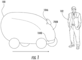
- FIG. 1 is an elevated side view of robot 100 interacting with person 102 in accordance with some implementations of this disclosure.
- the appearance of person 102 is for illustrative purposes only. Person 102 should be understood to represent any person regardless of height, gender, size, race, nationality, age, body shape, or other characteristics of a human other than characteristics explicitly discussed herein. Also, person 102 may not be a person at all. Instead, person 102 can be representative of an animal and/or other living creature that may interact with robot 100. Person 102 may also not be living, but rather have the appearance of a person and/or animal. For example, person 102 can be a robot, such as a robot designed to appear and/or behave like a human and/or animal.
- robot 100 can operate autonomously with little to no contemporaneous user control. However, in some implementations, robot 100 may be driven by a human and/or remote-controlled.
- Robot 100 can have a plurality of sensor units, such as sensor unit 104A and sensor unit 104B, which will be described in more detail with reference to FIG. 3A and FIG. 3B .
- Sensor unit 104A and sensor unit 104B can be used to detect the surroundings of robot 100, including any objects, people, animals, and/or anything else in the surrounding.
- a challenge that can occur in present technology is that present sensor unit systems, and methods using them, may detect the presence of objects, people, animals, and/or anything else in the surrounding, but may not differentiate between them.
- sensor unit 104A and sensor unit 104B can be used to differentiate the presence of people/animals from other objects.
- sensor unit 104A and sensor unit 104B can be positioned such that their fields of view extend from front side 700B of robot 100.
- FIG. 2 illustrates various side elevation views of exemplary body forms for robot 100 in accordance with principles of the present disclosure. These are non-limiting examples meant to further illustrate the variety of body forms, but not to restrict robot 100 to any particular body form.
- body form 250 illustrates an example where robot 100 is a stand-up shop vacuum.
- Body form 252 illustrates an example where robot 100 is a humanoid robot having an appearance substantially similar to a human body.
- Body form 254 illustrates an example where robot 100 is a drone having propellers.
- Body form 256 illustrates an example where robot 100 has a vehicle shape having wheels and a passenger cabin.
- Body form 258 illustrates an example where robot 100 is a rover.
- Body form 260 can be a motorized floor scrubber enabling it to move with little to no user exertion upon body form 260 besides steering. The user may steer body form 260 as it moves.
- Body form 262 can be a motorized floor scrubber having a seat, pedals, and a steering wheel, where a user can drive body form 262 like a vehicle as body form 262 cleans.
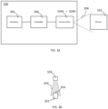
- FIG. 3A is a functional block diagram of one exemplary robot 100 in accordance with some implementations of the present disclosure.
- robot 100 includes controller 304, memory 302, and sensor units 104A - 104N, each of which can be operatively and/or communicatively coupled to each other and each other's components and/or subcomponents.
- the "N" in sensor units 104A - 104N indicates at least in part that there can be any number of sensor units, and this disclosure is not limited to any particular number of sensor units, nor does this disclosure require any number of sensor units.
- Controller 304 controls the various operations performed by robot 100. Although a specific implementation is illustrated in FIG. 3A , it is appreciated that the architecture may be varied in certain implementations as would be readily apparent to one of ordinary skill in the art given the contents of the present disclosure.
- Controller 304 can include one or more processors (e.g., microprocessors) and other peripherals.
- processors e.g., microprocessors
- the terms processor, microprocessor, and digital processor can include any type of digital processing devices such as, without limitation, digital signal processors ("DSPs"), reduced instruction set computers (“RISC”), general-purpose (“CISC”) processors, microprocessors, gate arrays (e.g., field programmable gate arrays (“FPGAs”)), programmable logic device (“PLDs”), reconfigurable computer fabrics (“RCFs”), array processors, secure microprocessors, and application-specific integrated circuits (“ASICs”).
- DSPs digital signal processors
- RISC reduced instruction set computers
- CISC general-purpose
- microprocessors e.g., gate arrays (e.g., field programmable gate arrays ("FPGAs”)), programmable logic device (“PLDs”), reconfigurable computer fabrics (“RCFs”), array processors,
- Controller 304 can be operatively and/or communicatively coupled to memory 302.
- Memory 302 can include any type of integrated circuit or other storage device adapted for storing digital data including, without limitation, read-only memory (“ROM”), random access memory (“RAM”), non-volatile random access memory (“NVRAM”), programmable read-only memory (“PROM”), electrically erasable programmable read-only memory (“EEPROM”), dynamic random-access memory (“DRAM”), Mobile DRAM, synchronous DRAM (“SDRAM”), double data rate SDRAM (“DDR/2 SDRAM”), extended data output RAM (“EDO”), fast page mode RAM (“FPM”), reduced latency DRAM (“RLDRAM”), static RAM (“SRAM”), flash memory (e.g., NAND/NOR), memristor memory, pseudostatic RAM (“PSRAM”), etc.
- ROM read-only memory
- RAM random access memory
- NVRAM non-volatile random access memory
- PROM programmable read-only memory
- EEPROM electrically era
- Memory 302 can provide instructions and data to controller 304.
- memory 302 can be a non-transitory, computer-readable storage medium having a plurality of instructions stored thereon, the instructions being executable by a processing apparatus (e.g., controller 304) to operate robot 100.
- the instructions can be configured to, when executed by the processing apparatus, cause the processing apparatus to perform the various methods, features, and/or functionality described in this disclosure.
- controller 304 can perform logical and arithmetic operations based on program instructions stored within memory 302.
- controllers and/or processors can serve as the various controllers and/or processors described.
- controllers and/or processors can be used, such as controllers and/or processors used particularly for one or more of sensor units 104A - 104N.
- Controller 304 can send and/or receive signals, such as power signals, control signals, sensor signals, interrogatory signals, status signals, data signals, electrical signals and/or any other desirable signals, including discrete and analog signals to sensor units 104A - 104N.
- Controller 304 can coordinate and/or manage sensor units 104A - 104N and other components/subcomponents, and/or set timings (e.g., synchronously or asynchronously), turn on/off, control power budgets, receive/send network instructions and/or updates, update firmware, send interrogatory signals, receive and/or send statuses, and/or perform any operations for running features of robot 100.
- timings e.g., synchronously or asynchronously
- one or more of sensor units 104A - 104N can comprise systems that can detect characteristics within and/or around robot 100.
- One or more of sensor units 104A - 104N can include sensors that are internal to robot 100 or external, and/or have components that are partially internal and/or partially external.
- One or more of sensor units 104A - 104N can include sensors such as sonar, Light Detection and Ranging (“LIDAR”) (e.g., 2D or 3D LIDAR), radar, lasers, video cameras, infrared cameras, 3D sensors, 3D cameras, and/or any other sensor known in the art.
- LIDAR Light Detection and Ranging
- one or more sensor units 104A - 104N can include a motion detector, including a motion detector using one or more of Passive Infrared ("PIR"), microwave, ultrasonic waves, tomographic motion detector, or video camera software.
- PIR Passive Infrared
- one or more of sensor units 104A - 104N can collect raw measurements (e.g., currents, voltages, resistances gate logic, etc.) and/or transformed measurements (e.g., distances, angles, detected points in people/animals/objects, etc.).
- one or more of sensor units 104A - 104N can have one or more field of view 306 from robot 100, where field of view 306 can be the detectable area of sensor units 104A - 104N.
- field of view 306 is a three-dimensional area in which the one or more sensors of sensor units 104A - 104N can send and/or receive data to sense at least some information regarding the environment within field of view 306.
- Field of view 306 can also be in a plurality of directions from robot 100 in accordance with how sensor units 104A - 104N are positioned.
- person 102 may be, at least in part, within field of view 306.
- FIG. 3B illustrates an example sensor unit 104 that includes a planar LIDAR in accordance with some implementations of this disclosure.
- Sensor unit 104 as used throughout this disclosure represents any one of sensor units 104A - 104N.
- the LIDAR can use light (e.g., ultraviolet, visible, near infrared light, etc.) to image items (e.g., people, animals, objects, bodies, etc.) in field of view 350 of the LIDAR. Within field of view 350, the LIDAR can detect items and determine their locations.
- light e.g., ultraviolet, visible, near infrared light, etc.
- image items e.g., people, animals, objects, bodies, etc.
- the LIDAR can detect items and determine their locations.
- the LIDAR can emit light, such as by sending pulses of light (e.g., in micropulses or high energy systems) with wavelengths including 532nm, 600 - 1000nm, 1064nm, 1550nm, or other wavelengths of light.
- the LIDAR can utilize coherent or incoherent detection schemes.
- a photodetector and/or receiving electronics of the LIDAR can read and/or record light signals, such as, without limitation, reflected light that was emitted from the LIDAR and/or other reflected and/or emitted light.
- sensor unit 104 and the LIDAR within, can create a point cloud of data, wherein each point of the point cloud is indicative at least in part of a point of detection on, for example, floors, obstacles, walls, objects, persons, animals, etc. in the surrounding.
- body 352 which can represent a moving body or a stationary body, can be at least in part within field of view 350 of sensor unit 104.
- Body 352 can have a surface 354 positioned proximally to sensor unit 104 such that sensor unit 104 detects at least surface 354.
- sensor unit 104 can detect the position of surface 354, which can be indicative at least in part of the location of body 352.
- the LIDAR is a planar LIDAR
- the point cloud can be on a plane. In some cases, each point of the point cloud has an associated approximate distance from the LIDAR.
- the LIDAR is not planar, such as a 3D LIDAR, the point cloud can be across a 3D area.
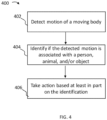
- FIG. 4 is a process flow diagram of an exemplary method 400 in which a robot 100 can identify moving bodies, such as people, animals, and/or objects, in accordance with some implementations of the present disclosure.
- Portion 402 includes detecting motion of a moving body.
- motion can be detected by one or more sensor units 104A - 104N.
- one or more sensor units 104A - 104N can detect motion based at least in part on a motion detector, such as the motion detectors described with reference to FIG. 3A as well as elsewhere throughout this disclosure.
- one or more of sensor units 104A - 104N can detect motion based at least in part on a difference signal, wherein robot 100 (e.g., using controller 304) determines the difference signal based at least in part on a difference (e.g., using subtraction) between data collected by one or more sensor units 104A - 104N at a first time from data collected by the same one or more sensor units 104A - 104N at a second time.
- the difference signal can reflect, at least in part, whether objects have moved because the positional measurements of those objects will change if there is movement between the times in which the one or more sensor units 104A - 104N collect data.
- robot 100 may itself be stationary or moving.
- robot 100 may be travelling in a forward, backward, right, left, up, down, or any other direction and/or combination of directions.
- the difference signal based at least in part on sensor data from sensor units 104A - 104N taken at a first time and a second time may be indicative at least in part of motion because robot 100 is actually moving, even when surrounding objects are stationary.
- Robot 100 can take into account its own movement by accounting for those movements (e.g., velocity, acceleration, etc.) in how objects are expected to appear.
- robot 100 can compensate for its own movements in detecting movement based on at least difference signals. As such, robot 100 can consider at least a portion of difference signals based at least in part on sensor data from sensor units 104A - 104N to be caused by movement of robot 100. In many cases, robot 100 can determine its own speed, acceleration, etc. using odometry, such as speedometers, accelerometers, gyroscopes, etc.
- a plurality of times can be used, and differences can be taken between one or more of them, such as data taken between a first time, second time, third time, fourth time, fifth time, and/or any other time.
- the data taken at a time can also be described as data taken in a frame because digital sensors can collect data in discrete frames.
- time can include a time value, time interval, period of time, instance of time, etc. Time can be measured in standard units (e.g., time of day) and/or relative times (e.g., number of seconds, minutes, hours, etc. between times).
- sensor unit 104 can collect data (e.g., sensor data) at a first time and a second time.
- This data can be a sensor measurement, image, and/or any other form of data generated by sensor unit 104.
- the data can include data generated by one or more LIDARs, radars, lasers, video cameras, infrared cameras, 3D sensors, 3D cameras, and/or any other sensors known in the art, such as those described with reference to FIG. 3A as well as elsewhere throughout this disclosure.
- the data collected at the first time can include at least a portion of data indicative at least in part of a person, animal, and/or object.
- the data indicative at least in part of the person, animal, and/or object can also be associated at least in part with a first position in space.
- the position can include distance measurements, such as absolute distance measurements using standard units, such as inches, feet, meters, or any other unit of measurement (e.g., measurements in the metric, US, or other system of measurement) or distance measurements having relative and/or non-absolute units, such as ticks, pixels, percentage of range of a sensor, and the like.
- the position can be represented as coordinates, such as (x, y) and/or (x, y, z). These coordinates can be global coordinates relative to a predetermined, stationary location (e.g., a starting location and/or any location identified as the origin). In some implementations, these coordinates can be relative to a moving location, such as relative to robot 100.
- the data collected at the second time may not include the portion of data indicative at least in part of the person, animal, and/or object. Because the data indicative at least in part of the person, animal, and/or object was present in the first time but not the second time, controller 304 can detect motion in some cases. The opposite can also be indicative of motion, wherein the data collected at the second time includes a portion of data indicative at least in part of a person, animal, and/or object and the data collected at the first time does not include the portion of data indicative at least in part of the person, animal, and/or object.
- robot 100 can also take into account its own movement, wherein robot 100 may expect that objects will move out of the field of vision of sensor 104 due to the motion of robot 100. Accordingly, robot 100 may not detect motion where an object moves in/out of view if going in/out of view was due to the movement of robot 100.
- the data collected at the second time does includes the portion of data indicative at least in part of the person, animal, and/or object associated at least in part with a second position in space, where the second position is not substantially similar to the first position.
- robot 100 e.g., controller 304
- a position threshold can be used.
- the position threshold can reduce false positives because differences in detected positions of objects may be subject to noise, movement by robot 100, measurement artifacts, etc.
- a position threshold can be set by a user, preprogrammed, and/or otherwise determined based at least in part on sensor noise, empirical determinations of false positives, velocity/acceleration of robot 100, known features of the environment, etc.
- the position threshold can be indicative at least in part of the amount of difference in position between the first position and the second position of a body such that robot 100 will not detect motion.
- the position threshold can be a percentage (e.g., percentage difference between positions) or a value, such as absolute and/or relative distance measurements. If a measure of the positional change of a body, such as a person, animal, and/or object, between times (e.g., between the first position and the second position) is greater than and/or equal to the position threshold, then robot 100 can detect motion.
- data collected at different times can also be compared, such as comparing data collected between each of the plurality of the aforementioned times, such as a first time, second time, third time, fourth time, fifth time, and/or any other time.
- robot 100 can sense a first position, second position, third position, fourth position, fifth position, and/or any other position in a substantially similar way as described with reference herein to the first position and the second position.
- comparing data at a plurality of times can increase robustness by providing additional sets of data in which to compare to detect motion of a moving body. For example, certain movements of positions may be small between times, falling below the position threshold.
- the difference between the second position and the first position may be within the position threshold, thereby within the tolerance of the robot not to detect motion.
- using a plurality of times can allow robot 100 to compare across multiple instances of time, further enhancing the ability to detect motion.
- the first time, second, time, third time, fourth time, fifth time, etc. can be periodic (e.g., substantially evenly spaced) or taken with variable time differences between one or more of them.
- certain times can be at sub-second time differences from one or more of each other.
- the times can be at an over a second difference from one or more of each other.
- the first time can be at 200 ms, the second time at 0.5 seconds, and the third time at 1 second.
- the times can be determined based at least on the resolution of one or more of sensor units 104A - 104N, noise (e.g., of the environment or of one or more of sensor units 104A - 104N), tolerance to false positives, and/or machine learning.
- walls can be more susceptible to false positives because walls are large objects, which can provide more area for noise.
- false detections can be due to the movement of robot 100, which can cause the stationary walls to appear as if they are moving.
- stationary objects there can be motion artifacts that are created by sensor noise.
- Other examples include stationary objects within field of view 306.
- robot 100 can have a map of the environment in which it is operating (e.g., navigating in some implementations). For example, robot 100 can obtain the map through user upload, download from a server, and/or generating the map based at least in part on data from one or more of sensor units 104A - 104N and/or other sensors.
- the map can include indications of the location of objects in the environment, including walls, boxes, shelves, and/or other features of the environment. Accordingly, as robot 100 operates in the environment, robot 100 can utilize a map to determine the location of objects in the environment, and therefore, dismiss detections of motion of at least some of those objects in the environment in the map as noise.
- robot 100 can also determine that bodies it detects substantially close to (e.g., within a predetermined distance threshold) stationary objects in maps are also not moving bodies.
- noise may be higher around stationary objects.
- robot 100 can cut down on false positives.
- a predetermined distance threshold can be 0.5, 1, 2, 3, or more feet. If motion is detected within the predetermined distance threshold from the moving bodies, the motion can be ignored.
- This predetermined distance threshold can be determined based at least in part on empirical data on false positives and/or false negatives, the velocity/acceleration in which robot 100 travels, the quality of map, sensor resolution, sensor noise, etc.
- determination of the difference signal can also take into account the movement of the robot. For example, robot 100 can compare a difference signal associated with at least the portion of data associated with the moving body with difference signals associated with other portions of the data from the same times (e.g., comparing a subset of a data set with other subsets of the data set at the same times). Because the moving body may have disproportionate movement relative to the rest of the data taken by robot 100 in the same time period, robot 100 can detect motion of the moving body.
- robot 100 can detect motion when the difference between the difference signal associated with at least the portion of data associated with a moving body and the difference signals associated with other data from the same times is greater than or equal to a predetermined threshold, such as a predetermined difference threshold. Accordingly, robot 100 can have at least some tolerance for differences wherein robot 100 does not detect motion. For example, differences can be due to noise, which can be produced due to motion artifacts, noise, resolution, etc.
- the predetermined difference threshold can be determined based at least on the resolution of one or more of sensor units 104A - 104N, noise (e.g., of the environment or of one or more of sensor units 104A - 104N), tolerance to false positives, and/or machine learning.
- robot 100 can project the motion of robot 100 and/or predict how stationary bodies will appear between one time and another. For example, robot 100 can predict (e.g., calculating based at least upon trigonometry), the change in the size of a stationary body as robot 100 moves closer, further away, or at an angle to that stationary body and/or the position of the stationary bodies as robot 100 moves relative to them. In some implementations, robot 100 can detect motion when the difference between the expected size of a body and the sensed size of the body is greater than or equal to a predetermined threshold, such as a predetermined size difference threshold. Accordingly, robot 100 can have some tolerance for differences wherein robot 100 does not detect motion.
- a predetermined threshold such as a predetermined size difference threshold. Accordingly, robot 100 can have some tolerance for differences wherein robot 100 does not detect motion.
- differences between actual and predicted sizes can be a result noise generated due to motion artifacts, noise, resolution, etc.
- the predetermined size threshold can be determined based at least on the resolution of one or more of sensor units 104A - 104N, noise (e.g., of the environment or of one or more of sensor units 104A - 104N), tolerance to false positives, and/or machine learning.
- robot 100 can further utilize machine learning, wherein robot 100 can learn to detect instances of motion by seeing instances motion. For example, a user can give robot 100 feedback based on an identification of motion by robot 100. In this way, based on at least the feedback, robot 100 can learn to associate characteristics of motion of moving bodies with an identification of motion.
- machine learning can allow robot 100 to adapt to more instances of motion of moving bodies, which robot 100 can learn while operating.
- Portion 404 can include identifying if the detected motion is associated with a person, animal, and/or object.
- robot 100 can process the data from one or more of sensor units 104A - 104N to determine one or more of the size, shape, and/or other distinctive features.
- distinctive features can include feet, arms, column-like shapes, etc.
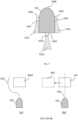
- FIG. 5A is a functional block diagram illustrating an elevated side view of sensor units 104A - 104B detecting moving body 500 in accordance with some implementations of this disclosure.
- Column-like shapes include shapes that are vertically elongated and at least partially continuous (e.g., connected). In some cases, the column-like shape can be entirely continuous. In some cases, the column-like shape can be substantially tubular and/or oval.
- Sensor unit 104A can include a planar LIDAR angled at angle 520, which can be the angle relative to a horizontal plane, or an angle relative to any other reference angle. Angle 520 can be the angle of sensor unit 104A as manufactured, or angle 520 can be adjusted by a user.
- angle 520 can be determined based at least in part on the desired horizontal range of the LIDAR (e.g., how far in front desirable for robot 100 to measure), the expected height of stationary or moving bodies, the speed of robot 100, designs of physical mounts on robot 100, and other features of robot 100, the LIDAR, and desired measurement capabilities.
- angle 520 can be approximately 20, 25, 30, 35, 40, 45, 50, or other degrees.
- the planar LIDAR of sensor unit 104A can sense along plane 502A (illustrated as a line from the illustrated view of FIG. 5A , but actually a plane as illustrated in FIG. 3B ).
- sensor unit 104B can include a planar LIDAR approximately horizontally positioned, where sensor unit 104B can sense along plane 502B (illustrated as a line from the illustrated view of FIG. 5A , but actually a plane as illustrated in FIG. 3B ). As illustrated, both plane 502A and plane 502B intersect (e.g., sense) moving body 500.
- plane 502A can intersect moving body 500 at intersect 524A.
- Plane 502B can intersect moving body 500 at intersect 524B. While intersects 524A - 524B appear as points from the elevated side view of FIG. 5A , intersects 524A - 524B are actually planar across a surface, in a substantially manner as illustrated in FIG. 3B .
- LIDAR is described for illustrative purposes, a person having ordinary skill in the art would recognize that any other sensor desirable can be used, including any described with reference to FIG. 3A as well as elsewhere throughout this disclosure.
- robot 100 can determine the position of intersect 524A and intersect 524B.
- intersect 524A and intersect 524B lie in approximately a plane (e.g., have substantially similar x-, y-, and/or z-coordinates)
- robot 100 can detect that the points may be part of an at least partially continuous body spanning between at least intersect 524A and intersect 524B.
- intersect 524A and intersect 524B can include at least two points in substantially the same vertical plane.
- robot 100 can process, compare, and/or merge the data of sensor unit 104A and sensor unit 104B to determine that moving body 500 has a vertical shape, such as a column-like body.
- sensor unit 104A and sensor unit 104B can each determine distances to intersect 524A and intersect 524B, respectively. If the distance in the horizontal direction (e.g., distance from robot 100) are substantially similar between at least some points within intersect 524A and interest 524B, robot 100 can determine that intersect 524A and intersect 524B are part of a column-like body that is at least partially continuous between intersect 524A and intersect 524B.
- a tolerance and/or a predetermined threshold such as a distance threshold, to determine how much different the horizontal distances can be before robot 100 no longer determines they are substantially similar.
- the difference threshold can be determined based at least on resolutions of sensor units 104A - 104B, noise, variations in bodies (e.g., people have arms, legs, and other body parts that might not be exactly planar), empirical data on false positives and/or false negatives, etc.
- robot 100 can detect moving body 500 as a column-like body in a plurality of ways in the alternative or in addition to the aforementioned. For example, robot 100 can assume that if it detects an object with both sensor unit 104A and sensor unit 104B, the object is a column-like body that is at least partially continuous between intersect 524A and intersect 524B. In some cases, there may be false positives in detecting, for example, walls, floors, and/or other stationary objects.
- Robot 100 can ignore the detection of walls, floors, and other stationary objects by not detecting a column-like body when it encounters such walls, floors, and other stationary objects using one or more of sensor units 104A - 104N, and/or robot 100 can recognize the detection of those walls, floors, and other stationary objects based at least in part on a map of the environment.
- robot 100 can utilize data taken over time to determine if data acquired from intersect 524A and intersect 524B corresponds to an at least partially continuous moving body 500.
- robot 100 can be moving and/or moving body 500 can be moving. Accordingly, the intersect between sensing planes 502A - 502B and a moving body 500 can result in sensor units 104A - 104B collecting data from different points along the moving body 500 at different times, allowing robot 100 to merge the data and determine that moving body is at least partially continuous.
- FIGS. 5B - 5C are functional block diagrams of the sensor units illustrated in FIG. 5A detecting person 102 in accordance with some principles of this disclosure.
- Person 102 can be a particular instance of moving body 500 from FIG. 5A .
- sensor units 104A - 104B detect person 102 at a first time. At this first time, sensor unit 104A collects data from intersect 504A and sensor unit 104B collects data from intersect 504B.
- sensor units 104A - 104B detect person 102 at a second time. Sensor unit 104A collects data from intersect 514A and sensor unit 104B collects data from intersect 514B.
- robot 100 can acquire additional data about person 102 at different times because sensor units 104A - 104B can measure different points on person 102.
- Robot 100 can further take additional measurements at a plurality of times, gathering data at even more points.
- robot 100 can merge the data to determine characteristics of moving body 500, such as person 102, from the measurements taken by sensor units 104A - 104B at a plurality of times.
- robot 100 can determine characteristics of moving body 500. For example, where moving body 500 is person 102, person 102 has features that may distinguish it from other moving bodies. For example, person 102 can have arms, such as arm 530. Person 102 can have legs, such as leg 532, where the legs also can have feet. Accordingly, robot 100 can detect these features of person 102 in order to determine that moving body 500 is person 102 (or an animal or a robot with body form substantially similar to a human or animal). Or in the absence of such features, determine that moving body 500 is not a person 102 (or not an animal or a robot with body form substantially similar to a human or animal).
- robot 100 can detect features of person 102 from at least portions of data collected by sensor units 104A - 104B.
- the portions of data collected by sensor units 104A - 104B can be indicative at least in part of those features, such as arms, legs, feet, etc.
- robot 100 can detect the characteristics of these features in a time (e.g., frame) of measurements. For example, in FIG.
- sensor 104A can detect the shape of arm 530 (e.g., rounded and/or ovular, having a hand, extending from person 102, and/or any other characteristic) and leg 532 (e.g., rounded and/or ovular, having a foot, extending downward from person 102, and/or any other characteristic).
- arm 530 e.g., rounded and/or ovular, having a hand, extending from person 102, and/or any other characteristic
- leg 532 e.g., rounded and/or ovular, having a foot, extending downward from person 102, and/or any other characteristic.
- These shapes can be determined from the sensor data.
- an image generated from the sensor data can show the shapes and/or characteristics of person 102.
- Robot 100 can identify those shapes and/or characteristics using visual systems, image processing, and/or machine learning.
- robot 100 can detect the characteristics of the features over a plurality of times (e.g., frames), such as the first time, second time, third, time, fourth time, fifth time, etc. aforementioned. For example, as previously described with reference to FIGS 5B - 5C , robot 100 can acquire additional data about person 102 at different times because sensor units 104A - 104B can measure different points on person 102. Robot 100 can further take additional measurements at a plurality of times, gathering data at even more points. As such, robot 100 can merge the data to determine characteristics of moving body 500 (e.g., person 102) from the measurements taken by sensor units 104A - 104B at a plurality of times.
- a plurality of times e.g., frames
- robot 100 can determine the characteristics, such as shapes, of features of person 102 (e.g., arms, legs, hands, feet, etc.) and determine that person 102 is a person (or an animal or a robot with body form substantially similar to a human or animal).
- characteristics such as shapes, of features of person 102 (e.g., arms, legs, hands, feet, etc.) and determine that person 102 is a person (or an animal or a robot with body form substantially similar to a human or animal).
- motion of limbs can be indicative at least in part that moving body 500 is a person 102.
- person 102 may swing his/her arm(s), legs, and/or other body parts while moving.
- Systems and methods of detecting motion such as those described with reference to FIGS. 5A, 5B, and 5C , as well as throughout this disclosure, can be used to detect motion associated with parts of person 102, such as arms, legs, and/or other body parts.
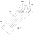
- FIG. 6 is an angled top view of sensor unit 104 detecting the swinging motion of legs 600A - 600B in accordance with some implementations of the present disclosure.
- Legs 600A - 600B can be legs of person 102 (and/or other animals, robots, etc.). In some cases, one or more of legs 600A - 600B can be natural legs. In some cases, one or more of legs 600A - 600B can include prosthetics and/or other components to facilitate motion of person 102. Accordingly, when person 102 walks, runs, and/or otherwise moves from one location to another, person 102 can move legs 600A - 600B. In some cases, person 102 can have a gait pattern.
- the gait cycle can involve a stance phase, including heel strike, flat foot, mid-stance, and push-off, and a swing phase, including acceleration, mid-swing, and deceleration.
- sensor unit 104 can have field of view 350. Using, for example, any of the methods aforementioned for detecting motion with reference to FIGS. 5A - 5C , as well as elsewhere throughout this disclosure, sensor unit 104 can detect the motion of the swinging leg of legs 600A - 600B. Also as described with reference to FIGS. 5A - 5C , as well as elsewhere throughout this disclosure, sensor unit 104 can also include a LIDAR, which can be used to detect the motion. Similar swinging motions can be detected in arms and/or other portions of person 102. In some implementations, sensor unit 104 can also detect the stationary leg of legs 600A - 600B.
- robot 100 can determine the presence of person 102 based at least in part on the swinging leg of legs 600A - 600B and/or the stationary leg of legs 600A - 600B.
- the combination of the swinging leg and stationary leg of person 102 can give a distinct pattern that sensor unit 104 can detect.
- controller 304 can identify moving body 500 as person 102 based at least in part on a swinging motion of at least a portion of a column-like moving body 500, such as the swinging leg of legs 600A - 600B.
- controller 304 can detect a swinging portion of column-like moving body 500 with a stationary portion in close proximity.
- the swinging portion can be the swinging leg of legs 600A - 600B, which can be detected by sensor unit 104 as a substantially tubular portion of moving body 500 in motion.
- Robot 100 can identify those shapes and/or characteristics using visual systems, image processing, and/or machine learning.
- the stationary leg of legs 600A - 600B can be detected by sensor unit 104 as a substantially vertical, substantially tubular portion of moving body 500. Detecting both the substantially tubular portion of moving body 500 in motion and substantially vertical, substantially tubular potion of moving body 500 can cause, at least in part, robot 100 to detect person 102.
- robot 100 using controller 304, can have a leg distance threshold, wherein when the distance between at least a portion of the substantially tubular portion of moving body 500 in motion and the substantially vertical, substantially tubular portion of moving body 500 is less than or equal to the predetermined leg distance threshold, robot 100 can determine that the substantially tubular portions are legs belonging to person 102 and detect person 102.
- the predetermined leg distance threshold can be determined based at least in part on the size of a person, field of view 350, the resolution of the sensor data, and/or other factors. This determination can occur at using data from at least two times (e.g., based at least in part on data from sensor 104 taken at two or more times).
- robot 100 can use data from sensor unit 104 taken at a plurality of times, in some cases more than at two times.
- controller 304 can identify person 102 by the alternate swinging pattern of the gait. For example, while walking, running, and/or otherwise moving, person 102 can alternate which of legs 600A - 600B is swinging and which of legs 600A - 600B is stationary. Indeed, this alternating motion allows person 102 to move. Accordingly, controller 304 can identify, from the data from sensor unit 104, the alternating motion of the legs.
- controller 304 can identify, from the data from sensor unit 104, the alternating motion of the legs.
- robot 100 can detect that leg 600A is swinging and leg 600B is stationary at a first time and/or set of times. At a second time and/or set of times, using these same systems and methods, robot 100 can detect that leg 600A is stationary and leg 600B is swinging. According, because of this alternation, robot 100 can determine that moving body 500 is person 102. For additional robustness, more alternations can be taken into account. For example, an alternation threshold can be used, wherein if robot 100 detects a predetermined number of alternating swinging states between leg 600A and leg 600B, robot 100 can determine that moving body 500 is person 102.
- the predetermined number of alternating swinging states can be determined based at least in part on the speed robot 100 is moving, the size of field of view 350, the tolerance to false positives, sensor sensitivity, empirically determined parameters, and/or other factors.
- the predetermined number of alternating swing states can be 2, 3, 4, 5, or more alternations.
- FIG. 7 is a top view of an example robot 100 having a plurality of sensor units 104C - 104E in accordance with some implementations of this disclosure.
- sensor unit 104C can be positioned on left side 700C of robot 100, with field of view 702C from sensor unit 104C extending in a direction at least towards back side 700D.
- field of view 702C can allow sensor unit 104C to detect moving body 500 approaching left side 700C of robot 100 because such moving body 500 can be detected within field of view 702C.
- sensor unit 104E can be positioned on right side 700E of robot 100, with field of view 702E from sensor unit 104E extending in a direction at least towards back side 700D.
- field of view 702E can allow sensor unit 104E to detect moving body 500 approaching right side 700E of robot 100 because such moving body 500 can be detected within field of view 702E.
- Sensor unit 104D can be positioned on back side 700D of robot 100, with field of view 702D from sensor unit 104D extending a direction at least distally from back side 700D.
- field of view 702D can allow sensor unit 104D to detect moving body 500 approaching from back side 700D.
- robot 100 can determine that moving body 500 is person 102 based at least in part of moving body 500 being detected by at least one of sensor units 104C - 104E. In such a detection, in some implementations, robot 100 may be moving or stationary. For example, in some implementations, any detection in fields of view 702C, 702D, and 702E (of sensor units 104C, 104D, and 104E, respectively) can be determined by robot 100 to be from person 102.
- robot 100 can assume moving body 500 is person 102.
- a detection of moving body 500 at one of fields of view 702C, 702D, and 702E can be indicative at least in part of person 102 moving to catch robot 102.
- each of sensors 104C, 104D, and 104E can detect motion and/or identify person 102 using systems and methods substantially similar to those described in this disclosure with reference to sensor 104.
- controller 304 can utilize machine learning to identify the gait motion of legs 600A - 600B based at least in part on sensor data from sensor unit 104 taken at one or more times.
- a library stored on a server and/or within memory 302, can comprise example sensor data of people (or animals or robots with body form substantially similar to a human or animal), such as LIDAR data indicative of a person. Any other data of any other sensor described in this disclosure, such as with reference to FIG. 3A , can be in the library. That LIDAR data can include data relating to, at least in part, motion and/or the existence of one or more of arms, legs, and/or other features of a person.
- the library can then be used in a supervised or unsupervised machine learning algorithm for controller 304 to learn to identify/associate patterns in sensor data with people.
- the sensor data of the library can be identified (e.g., labelled by a user (e.g., hand-labelled) or automatically, such as with a computer program that is configured to generate/simulate library sensor data and/or label that data).
- the library can also include data of people (or animals or robots with body form substantially similar to a human or animal) in different lighting conditions, angles, sizes (e.g., distances), clarity (e.g., blurred, obstructed/occluded, partially off frame, etc.), colors, temperatures, surroundings, etc. From this library data, controller 304 can first be trained to identify people. Controller 304 can then use that training to identify people in data obtained in portion 402 and/or portion 404.
- controller 304 can be trained from the library to identify patterns in library data and associate those patterns with people. When data obtained in portion 402 and/or portion 404 has the patterns that controller 304 identified and associated to people, controller 304 can determine that the data obtained in portion 402 and/or portion 404 contains a person and/or the location of the person in the obtained data. In some implementations, controller 304 can process data obtained in portion 402 and portion 404 and compare that data to at least some data in the library. In some cases, where obtained data substantially matches data in the library, controller 304 can identify the obtained data as containing a person and/or the location of the person in the obtained data.
- people can be identified from the sensor data based at least on size and/or shape information wherein, the size and/or shape of the moving object, as represented in the sensor data, has the appearance of a person.
- additional robustness can be built into the detection. Such robustness can be useful, for example, due to noise and/or aberrations in sensor units 104A - 104B, false detections can occur.
- one or both of sensor units 104A - 104B can make a detection that is not there.
- an object can quickly move out of the field of view of sensor units 104A - 104B.
- robot 100 can incorrectly identify the presence of a person 102 and behave accordingly.
- robot 100 can clear data associated with one or more sensor units 104A - 104B at the time the false detection occurred, such as clearing data collected at a time in a manner described with reference to FIGS. 5A - 5C , as well as elsewhere throughout this disclosure. This ability can allow robot 100 to avoid making a false detection.
- one of sensor units 104A - 104B can be used clear detections.
- robot 100 can predict a movement of moving body. For example, robot 100 can determine the acceleration, position, and/or velocity of moving body 500 at a time or plurality of times. Based at least in part on that acceleration, position, and/or velocity, robot 100 can predict where moving body 500 will be. In some implementations, the prediction can be based on predetermined associations between acceleration, position, and/or velocity and movement of moving body 500. In some cases, the associations can be determined empirically, based on general physical properties, etc. For example, if moving body 500 is moving to the right at a first time, robot 100 can predict that a subsequent time, moving body 500 will be right of the position moving body 500 was at the first time. Based on the velocity and/or acceleration of moving body 500, and the amount of time that has lapsed, robot 100 can predict how much moving body 500 moves.
- robot 100 can determine a probability to various positions.
- assigning probabilities to various positions can account for changes in movements of moving body 500. For example, where moving body 500 is person 102, person 102 can change directions, suddenly stop, etc. Accordingly, robot 100 can assign probabilities associated with different positions moving body 500 can be in. In some cases, such probabilities can be determined using Bayesian statistical models based at least in part on empirically determined movements, general physical properties, etc. In some cases, the probabilities can be represented in a volume image, wherein positions in space (e.g., in a 2D image or in a 3D image) can be associated with a probability. In some cases, there can be positions with high probabilities, wherein the probabilities form a probabilistic tail, tailing off at less likely positions.
- robot 100 can determine that it has not made a false detection (and/or not determine that it has made a false detection). Where moving body 500 has detected a position with a low probability, robot 100 may collect more data (e.g., take more measurements at different times and/or consider more data already taken) and/or determine that robot 100 has made a false detection.
- portion 406 can include taking action based at least in part on the identification from portion 404. For example, in response to detecting a person 102 in portion 404, robot 100 can slow down, stop, and/or modify plans accordingly.
- FIG. 8A is an overhead view of a functional diagram of a path robot 100 can use to navigate around an object 800A in accordance with some implementations of the present disclosure.
- Robot 100 can go in a path 802 around object 800A in order to avoid running into object 800A.
- challenges can occur when object 800A is moving. For example, the movement of object 800A could cause robot 100 to navigate further from the unaltered path of robot 100 and/or cause robot 100 to run into object 800A.
- FIG. 8B is an overhead view of a functional diagram of a path robot 100 can use to navigate around person 102 in accordance with some implementations of the present disclosure.
- Person 102 can move to position 806. If robot 100 identified moving body 500 as person 102 in portion 404, robot 100 can perform an action based at least in part on that determination. For example, robot 100 can slow down and/or stop along path 804 and allow person 102 to pass.
- path 804 can be the path that robot 100 was traveling in the absence of the presence of person 102.
- robot 100 can slow down sufficiently so that robot 100 approaches person 102 at a speed that allows person 102 to pass. Once robot 100 has passed person 102, it can speed up. As another example, robot 100 can come to a complete stop and wait for person 102 to pass.
- allowing person 102 to pass can allow robot 100 to avoid running into person 102, avoid deviating from the path robot 100 was travelling, and/or give person 102 a sense that robot 100 has detected him/her.
- robot 100 can monitor the motion of person 102. Once person 102 has moved out of the fields of view of sensor units 104A - 104N, robot 100 can speed up and/or resume from a stopped position along path 804. In some implementations, robot 100 can wait a predetermined time before attempting to continue on path 804. The predetermined time can be determined based at least in part upon the speed of robot 100 (e.g., slowed down, stopped, or otherwise), the speed of person 102, the acceleration of robot 100, empirical data on times it takes for person 102 to pass, and/or any other information. After the predetermined time, robot 100 can attempt to pass again. In some cases, path 804, or a substantially similar path, can be clear.
- robot 100 may wait again after the predetermined time if path 804 is still blocked. In some cases, if path 804 is still blocked after the predetermined time, robot 100 can swerve around the object (e.g., in a manner similar to path 802 as illustrated in FIG. 8A ).
- robot 100 can slow down and/or stop.
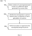
- FIG. 9 is a process flow diagram of an exemplary method 900 for detecting and responding to person 102 in accordance with some implementations of this disclosure.
- Portion 902 includes detecting motion of a moving body based at least on a difference signal generated from sensor data.
- Portion 904 includes identifying the moving body is a person based at least on detecting at least a gait pattern of a person.
- Portion 906 includes performing an action in response to the moving body being the person.
- computer and/or computing device can include, but are not limited to, personal computers (“PCs”) and minicomputers, whether desktop, laptop, or otherwise, mainframe computers, workstations, servers, personal digital assistants ("PDAs”), handheld computers, embedded computers, programmable logic devices, personal communicators, tablet computers, mobile devices, portable navigation aids, J2ME equipped devices, cellular telephones, smart phones, personal integrated communication or entertainment devices, and/or any other device capable of executing a set of instructions and processing an incoming data signal.
- PCs personal computers
- PDAs personal digital assistants
- handheld computers handheld computers
- embedded computers embedded computers
- programmable logic devices personal communicators
- tablet computers tablet computers
- mobile devices portable navigation aids
- J2ME equipped devices portable navigation aids
- cellular telephones smart phones
- personal integrated communication or entertainment devices personal integrated communication or entertainment devices
- computer program and/or software can include any sequence or human or machine cognizable steps which perform a function.
- Such computer program and/or software may be rendered in any programming language or environment including, for example, C/C++, C#, Fortran, COBOL, MATLAB TM , PASCAL, Python, assembly language, markup languages (e.g., HTML, SGML, XML, VoXML), and the like, as well as object-oriented environments such as the Common Object Request Broker Architecture ("CORBA"), JAVA TM (including J2ME, Java Beans, etc.), Binary Runtime Environment (e.g., BREW), and the like.
- CORBA Common Object Request Broker Architecture
- JAVA TM including J2ME, Java Beans, etc.
- BREW Binary Runtime Environment
- connection, link, transmission channel, delay line, and/or wireless can include a causal link between any two or more entities (whether physical or logical/virtual), which enables information exchange between the entities.
- the term “including” should be read to mean “including, without limitation,” “including but not limited to,” or the like; the term “comprising” as used herein is synonymous with “including,” “containing,” or “characterized by,” and is inclusive or open-ended and does not exclude additional, unrecited elements or method steps; the term “having” should be interpreted as “having at least;” the term “such as” should be interpreted as “such as, without limitation;” the term 'includes” should be interpreted as “includes but is not limited to;” the term “example” is used to provide exemplary instances of the item in discussion, not an exhaustive or limiting list thereof, and should be interpreted as “example, but without limitation;” adjectives such as "known,” “normal,” “standard,” and terms of similar meaning should not be construed as limiting the item described to a given time period or to an item available as of a given time, but instead should be read to encompass known, normal, or standard technologies that may be available
- a group of items linked with the conjunction "and” should not be read as requiring that each and every one of those items be present in the grouping, but rather should be read as “and/or” unless expressly stated otherwise.
- a group of items linked with the conjunction “or” should not be read as requiring mutual exclusivity among that group, but rather should be read as “and/or” unless expressly stated otherwise.
- the terms "about” or “approximate” and the like are synonymous and are used to indicate that the value modified by the term has an understood range associated with it, where the range can be ⁇ 20%, ⁇ 15%, ⁇ 10%, ⁇ 5%, or ⁇ 1%.
- a result e.g., measurement value
- close can mean, for example, the result is within 80% of the value, within 90% of the value, within 95% of the value, or within 99% of the value.
- defined or “determined” can include “predefined” or “predetermined” and/or otherwise determined values, conditions, thresholds, measurements, and the like.
Landscapes
- Engineering & Computer Science (AREA)
- Mechanical Engineering (AREA)
- Robotics (AREA)
- Automation & Control Theory (AREA)
- Physics & Mathematics (AREA)
- General Physics & Mathematics (AREA)
- Fuzzy Systems (AREA)
- Software Systems (AREA)
- Mathematical Physics (AREA)
- Artificial Intelligence (AREA)
- Evolutionary Computation (AREA)
- Human Computer Interaction (AREA)
- Manufacturing & Machinery (AREA)
- Transportation (AREA)
- Multimedia (AREA)
- Theoretical Computer Science (AREA)
- Manipulator (AREA)
- Toys (AREA)
- Control Of Position, Course, Altitude, Or Attitude Of Moving Bodies (AREA)
- Image Analysis (AREA)
Applications Claiming Priority (2)
| Application Number | Priority Date | Filing Date | Title |
|---|---|---|---|
| US15/199,224 US10016896B2 (en) | 2016-06-30 | 2016-06-30 | Systems and methods for robotic behavior around moving bodies |
| PCT/US2017/040324 WO2018005986A1 (en) | 2016-06-30 | 2017-06-30 | Systems and methods for robotic behavior around moving bodies |
Publications (4)
| Publication Number | Publication Date |
|---|---|
| EP3479568A1 EP3479568A1 (en) | 2019-05-08 |
| EP3479568A4 EP3479568A4 (en) | 2020-02-19 |
| EP3479568C0 EP3479568C0 (en) | 2023-08-16 |
| EP3479568B1 true EP3479568B1 (en) | 2023-08-16 |
Family
ID=60787629
Family Applications (1)
| Application Number | Title | Priority Date | Filing Date |
|---|---|---|---|
| EP17821370.8A Active EP3479568B1 (en) | 2016-06-30 | 2017-06-30 | Systems and methods for robotic behavior around moving bodies |
Country Status (7)
Families Citing this family (24)
| Publication number | Priority date | Publication date | Assignee | Title |
|---|---|---|---|---|
| US10471904B2 (en) * | 2016-08-08 | 2019-11-12 | Toyota Motor Engineering & Manufacturing North America, Inc. | Systems and methods for adjusting the position of sensors of an automated vehicle |
| KR102624560B1 (ko) * | 2017-01-31 | 2024-01-15 | 엘지전자 주식회사 | 청소기 |
| US20230107110A1 (en) * | 2017-04-10 | 2023-04-06 | Eys3D Microelectronics, Co. | Depth processing system and operational method thereof |
| WO2018191818A1 (en) | 2017-04-18 | 2018-10-25 | Clearpath Robotics Inc. | Stand-alone self-driving material-transport vehicle |
| WO2018213931A1 (en) * | 2017-05-25 | 2018-11-29 | Clearpath Robotics Inc. | Systems and methods for process tending with a robot arm |
| WO2019041043A1 (en) | 2017-08-31 | 2019-03-07 | Clearpath Robotics Inc. | SYSTEMS AND METHODS FOR GENERATING A MISSION FOR A SELF-CONTAINING MATERIAL TRANSPORT VEHICLE |
| US11064168B1 (en) * | 2017-09-29 | 2021-07-13 | Objectvideo Labs, Llc | Video monitoring by peep hole device |
| US20190100306A1 (en) * | 2017-09-29 | 2019-04-04 | Intel IP Corporation | Propeller contact avoidance in an unmanned aerial vehicle |
| WO2019084686A1 (en) | 2017-10-31 | 2019-05-09 | Clearpath Robotics Inc. | Systems and methods for operating robotic equipment in controlled zones |
| US10775793B2 (en) * | 2017-12-22 | 2020-09-15 | The Boeing Company | Systems and methods for in-flight crew assistance |
| US10863668B2 (en) * | 2017-12-29 | 2020-12-15 | Dcentralized Systems, Inc. | Autonomous mobile platform with harvesting system and pest and weed suppression systems |
| WO2019191313A1 (en) | 2018-03-27 | 2019-10-03 | Nvidia Corporation | Remote operation of vehicles using immersive virtual reality environments |
| KR102067600B1 (ko) * | 2018-05-16 | 2020-01-17 | 엘지전자 주식회사 | 청소기 및 그 제어방법 |
| EP4043981A1 (en) * | 2019-02-11 | 2022-08-17 | Tusimple, Inc. | Vehicle-based rotating camera methods and systems |
| WO2019172733A2 (ko) * | 2019-05-08 | 2019-09-12 | 엘지전자 주식회사 | 감지대상체와 상호작용이 가능한 이동로봇 및 이동로봇과 감지대상체의 상호작용 방법 |
| US11565411B2 (en) * | 2019-05-29 | 2023-01-31 | Lg Electronics Inc. | Intelligent robot cleaner for setting travel route based on video learning and managing method thereof |
| DE102019213009A1 (de) * | 2019-08-29 | 2021-03-04 | Robert Bosch Gmbh | Aufbereitung von Radarsignalen mit Unterdrückung von Bewegungsartefakten |
| KR102570854B1 (ko) * | 2019-12-26 | 2023-08-28 | 주식회사 제타뱅크 | 이동 로봇 및 그 서비스 안내 방법 |
| US12122367B2 (en) | 2020-09-10 | 2024-10-22 | Rockwell Automation Technologies, Inc. | Systems and methods for operating one or more self-driving vehicles |
| CN112428269B (zh) * | 2020-11-11 | 2022-03-08 | 合肥学院 | 一种巡检机器人用障碍报警系统 |
| EP4328887A4 (en) * | 2021-04-23 | 2025-03-05 | Mitsubishi Electric Corporation | Moving body, waste collection system, and control device |
| EP4108390B1 (de) * | 2021-06-25 | 2023-08-02 | Sick Ag | Verfahren zum sicheren betrieb eines beweglichen maschinenteils |
| KR20230095585A (ko) * | 2021-12-22 | 2023-06-29 | 엘지전자 주식회사 | 안내 로봇 및 그것의 동작 방법 |
| WO2025094588A1 (ja) * | 2023-10-30 | 2025-05-08 | 株式会社小糸製作所 | 制御装置、プログラム、及び監視システム |
Citations (2)
| Publication number | Priority date | Publication date | Assignee | Title |
|---|---|---|---|---|
| US20060049939A1 (en) * | 2004-09-08 | 2006-03-09 | Sick Ag | Method and apparatus for the control of a safety-relevant function of a machine |
| WO2016022155A1 (en) * | 2014-08-08 | 2016-02-11 | Robotic Vision Technologies, LLC | Sensor-based safety features for robotic equipment |
Family Cites Families (206)
| Publication number | Priority date | Publication date | Assignee | Title |
|---|---|---|---|---|
| US5280179A (en) | 1979-04-30 | 1994-01-18 | Sensor Adaptive Machines Incorporated | Method and apparatus utilizing an orientation code for automatically guiding a robot |
| US4638445A (en) | 1984-06-08 | 1987-01-20 | Mattaboni Paul J | Autonomous mobile robot |
| US5121497A (en) | 1986-03-10 | 1992-06-09 | International Business Machines Corporation | Automatic generation of executable computer code which commands another program to perform a task and operator modification of the generated executable computer code |
| US4763276A (en) | 1986-03-21 | 1988-08-09 | Actel Partnership | Methods for refining original robot command signals |
| US4852018A (en) | 1987-01-07 | 1989-07-25 | Trustees Of Boston University | Massively parellel real-time network architectures for robots capable of self-calibrating their operating parameters through associative learning |
| US5155684A (en) | 1988-10-25 | 1992-10-13 | Tennant Company | Guiding an unmanned vehicle by reference to overhead features |
| FR2648071B1 (fr) | 1989-06-07 | 1995-05-19 | Onet | Procede et appareil autonomes de nettoyage automatique de sol par execution de missions programmees |
| WO1991006050A1 (en) | 1989-10-17 | 1991-05-02 | Applied Biosystems, Inc. | Robotic interface |
| US5640323A (en) | 1990-02-05 | 1997-06-17 | Caterpillar Inc. | System and method for operating an autonomous navigation system |
| US8352400B2 (en) | 1991-12-23 | 2013-01-08 | Hoffberg Steven M | Adaptive pattern recognition based controller apparatus and method and human-factored interface therefore |
| US5673367A (en) | 1992-10-01 | 1997-09-30 | Buckley; Theresa M. | Method for neural network control of motion using real-time environmental feedback |
| CA2081519C (en) | 1992-10-27 | 2000-09-05 | The University Of Toronto | Parametric control device |
| KR0161031B1 (ko) | 1993-09-09 | 1998-12-15 | 김광호 | 로보트의 위치오차보정장치 |
| US5602761A (en) | 1993-12-30 | 1997-02-11 | Caterpillar Inc. | Machine performance monitoring and fault classification using an exponentially weighted moving average scheme |
| WO1997010081A1 (fr) | 1995-09-11 | 1997-03-20 | Kabushiki Kaisha Yaskawa Denki | Circuit de commande de robots |
| US6169981B1 (en) | 1996-06-04 | 2001-01-02 | Paul J. Werbos | 3-brain architecture for an intelligent decision and control system |
| US6366293B1 (en) | 1998-09-29 | 2002-04-02 | Rockwell Software Inc. | Method and apparatus for manipulating and displaying graphical objects in a computer display device |
| US6243622B1 (en) | 1998-10-16 | 2001-06-05 | Xerox Corporation | Touchable user interface using self movable robotic modules |
| EP1037134A2 (en) | 1999-03-16 | 2000-09-20 | Matsushita Electric Industrial Co., Ltd. | Virtual space control data receiving apparatus and method |
| US6124694A (en) | 1999-03-18 | 2000-09-26 | Bancroft; Allen J. | Wide area navigation for a robot scrubber |
| CN1161700C (zh) | 1999-04-30 | 2004-08-11 | 索尼公司 | 网络系统 |
| JP3537362B2 (ja) | 1999-10-12 | 2004-06-14 | ファナック株式会社 | ロボットシステム用グラフィック表示装置 |
| AU2001250802A1 (en) | 2000-03-07 | 2001-09-17 | Sarnoff Corporation | Camera pose estimation |
| JP2001260063A (ja) * | 2000-03-21 | 2001-09-25 | Sony Corp | 多関節型ロボット及びその動作制御方法 |
| US6754560B2 (en) | 2000-03-31 | 2004-06-22 | Sony Corporation | Robot device, robot device action control method, external force detecting device and external force detecting method |
| JP4480843B2 (ja) * | 2000-04-03 | 2010-06-16 | ソニー株式会社 | 脚式移動ロボット及びその制御方法、並びに、脚式移動ロボット用相対移動測定センサ |
| US8543519B2 (en) | 2000-08-07 | 2013-09-24 | Health Discovery Corporation | System and method for remote melanoma screening |
| JP4765155B2 (ja) | 2000-09-28 | 2011-09-07 | ソニー株式会社 | オーサリング・システム及びオーサリング方法、並びに記憶媒体 |
| US6678413B1 (en) | 2000-11-24 | 2004-01-13 | Yiqing Liang | System and method for object identification and behavior characterization using video analysis |
| JP2002197437A (ja) * | 2000-12-27 | 2002-07-12 | Sony Corp | 歩行検出システム、歩行検出装置、デバイス、歩行検出方法 |
| US6442451B1 (en) | 2000-12-28 | 2002-08-27 | Robotic Workspace Technologies, Inc. | Versatile robot control system |
| JP2002239960A (ja) | 2001-02-21 | 2002-08-28 | Sony Corp | ロボット装置の動作制御方法、プログラム、記録媒体及びロボット装置 |
| US20020175894A1 (en) | 2001-03-06 | 2002-11-28 | Vince Grillo | Hand-supported mouse for computer input |
| US6917925B2 (en) | 2001-03-30 | 2005-07-12 | Intelligent Inference Systems Corporation | Convergent actor critic-based fuzzy reinforcement learning apparatus and method |
| JP2002301674A (ja) | 2001-04-03 | 2002-10-15 | Sony Corp | 脚式移動ロボット及びその運動教示方法、並びに記憶媒体 |
| EP1254688B1 (en) | 2001-04-30 | 2006-03-29 | Sony France S.A. | autonomous robot |
| US6584375B2 (en) | 2001-05-04 | 2003-06-24 | Intellibot, Llc | System for a retail environment |
| US6636781B1 (en) | 2001-05-22 | 2003-10-21 | University Of Southern California | Distributed control and coordination of autonomous agents in a dynamic, reconfigurable system |
| JP3760186B2 (ja) | 2001-06-07 | 2006-03-29 | 独立行政法人科学技術振興機構 | 二脚歩行式移動装置及びその歩行制御装置並びに歩行制御方法 |
| JP4188607B2 (ja) | 2001-06-27 | 2008-11-26 | 本田技研工業株式会社 | 二足歩行移動体の床反力推定方法及び二足歩行移動体の関節モーメント推定方法 |
| WO2003007129A2 (en) | 2001-07-13 | 2003-01-23 | Broks Automation, Inc. | Trajectory planning and motion control strategies for a planar three-degree-of-freedom robotic arm |
| US6710346B2 (en) | 2001-08-02 | 2004-03-23 | International Business Machines Corporation | Active infrared presence sensor |
| AU2002331786A1 (en) | 2001-08-31 | 2003-03-18 | The Board Of Regents Of The University And Community College System, On Behalf Of The University Of | Coordinated joint motion control system |
| JP4607394B2 (ja) | 2001-09-27 | 2011-01-05 | 株式会社シー・イー・デー・システム | 人物検出システム、及び人物検出プログラム |
| US6812846B2 (en) | 2001-09-28 | 2004-11-02 | Koninklijke Philips Electronics N.V. | Spill detector based on machine-imaging |
| US7243334B1 (en) | 2002-01-16 | 2007-07-10 | Prelude Systems, Inc. | System and method for generating user interface code |
| JP3790816B2 (ja) | 2002-02-12 | 2006-06-28 | 国立大学法人 東京大学 | 人型リンク系の運動生成方法 |
| EP1534591A2 (en) | 2002-04-22 | 2005-06-01 | Neal E. Solomon | System, method and apparatus for automated collective mobile robotic vehicles used in remote sensing surveillance |
| US7505604B2 (en) | 2002-05-20 | 2009-03-17 | Simmonds Precision Prodcuts, Inc. | Method for detection and recognition of fog presence within an aircraft compartment using video images |
| US7834754B2 (en) | 2002-07-19 | 2010-11-16 | Ut-Battelle, Llc | Method and system for monitoring environmental conditions |
| JP2005539296A (ja) | 2002-08-21 | 2005-12-22 | ニール,ソロモン | マルチ−ロボットシステム内での自己設定可能なモバイルロボットエージェントの組織化団体の為のシステムと方法と装置 |
| JP2004170166A (ja) * | 2002-11-19 | 2004-06-17 | Eiji Shimizu | グレイコードを用いた相対移動距離と相対ずれ角の測定方法およびそれを応用した装置とシステム |
| AU2003900861A0 (en) | 2003-02-26 | 2003-03-13 | Silverbrook Research Pty Ltd | Methods,systems and apparatus (NPS042) |
| JP3950805B2 (ja) | 2003-02-27 | 2007-08-01 | ファナック株式会社 | 教示位置修正装置 |
| US7313279B2 (en) | 2003-07-08 | 2007-12-25 | Computer Associates Think, Inc. | Hierarchical determination of feature relevancy |
| GB2400353A (en) * | 2003-04-09 | 2004-10-13 | Autoliv Dev | Pedestrian detecting system provided on a motor vehicle |
| SE0301531L (sv) | 2003-05-22 | 2004-11-23 | Abb Ab | A Control method for a robot |
| US7212651B2 (en) | 2003-06-17 | 2007-05-01 | Mitsubishi Electric Research Laboratories, Inc. | Detecting pedestrians using patterns of motion and appearance in videos |
| US7769487B2 (en) | 2003-07-24 | 2010-08-03 | Northeastern University | Process and architecture of robotic system to mimic animal behavior in the natural environment |
| WO2005028166A1 (ja) | 2003-09-22 | 2005-03-31 | Matsushita Electric Industrial Co., Ltd. | 弾性体アクチュエータの制御装置及び制御方法 |
| US7342589B2 (en) | 2003-09-25 | 2008-03-11 | Rockwell Automation Technologies, Inc. | System and method for managing graphical data |
| JP4592276B2 (ja) | 2003-10-24 | 2010-12-01 | ソニー株式会社 | ロボット装置のためのモーション編集装置及びモーション編集方法、並びにコンピュータ・プログラム |
| US7339339B2 (en) | 2004-02-25 | 2008-03-04 | The Ritsumeikan Trust | Control system of floating mobile body |
| JP4661074B2 (ja) | 2004-04-07 | 2011-03-30 | ソニー株式会社 | 情報処理システム、情報処理方法、並びにロボット装置 |
| EP1622072B1 (en) | 2004-07-27 | 2010-07-07 | Sony France S.A. | An automated action-selection system and method and application thereof for training prediction machines and for driving the development of self-developing devices |
| JP2006110072A (ja) * | 2004-10-14 | 2006-04-27 | Mitsubishi Heavy Ind Ltd | 非接触歩行検出方法とシステム及び該システムを用いた個人認証方法とシステム |
| SE0402672D0 (sv) | 2004-11-02 | 2004-11-02 | Viktor Kaznov | Ball robot |
| US7211979B2 (en) | 2005-04-13 | 2007-05-01 | The Broad Of Trustees Of The Leland Stanford Junior University | Torque-position transformer for task control of position controlled robots |
| US7765029B2 (en) | 2005-09-13 | 2010-07-27 | Neurosciences Research Foundation, Inc. | Hybrid control device |
| JP4876511B2 (ja) | 2005-09-29 | 2012-02-15 | 株式会社日立製作所 | ロジック抽出支援装置 |
| EP1941411B1 (en) | 2005-09-30 | 2011-09-14 | iRobot Corporation | Companion robot for personal interaction |
| US7668605B2 (en) | 2005-10-26 | 2010-02-23 | Rockwell Automation Technologies, Inc. | Wireless industrial control user interface |
| ATE534941T1 (de) | 2005-12-02 | 2011-12-15 | Irobot Corp | Abdeckungsrobotermobilität |
| US7741802B2 (en) | 2005-12-20 | 2010-06-22 | Intuitive Surgical Operations, Inc. | Medical robotic system with programmably controlled constraints on error dynamics |
| US8239083B2 (en) | 2006-01-18 | 2012-08-07 | I-Guide Robotics, Inc. | Robotic vehicle controller |
| US8224018B2 (en) | 2006-01-23 | 2012-07-17 | Digimarc Corporation | Sensing data from physical objects |
| US7576639B2 (en) | 2006-03-14 | 2009-08-18 | Mobileye Technologies, Ltd. | Systems and methods for detecting pedestrians in the vicinity of a powered industrial vehicle |
| JP4839939B2 (ja) * | 2006-04-17 | 2011-12-21 | トヨタ自動車株式会社 | 自律移動装置 |
| US8924021B2 (en) | 2006-04-27 | 2014-12-30 | Honda Motor Co., Ltd. | Control of robots from human motion descriptors |
| JP4320363B2 (ja) | 2006-05-25 | 2009-08-26 | 豪洋 石崎 | 作業ロボット |
| KR100791382B1 (ko) | 2006-06-01 | 2008-01-07 | 삼성전자주식회사 | 로봇의 이동 경로에 따라 소정 영역의 특성에 관한 정보를수집하고 분류하는 방법 및 상기 영역 특성에 따라제어되는 로봇, 상기 영역 특성을 이용한 ui 구성 방법및 장치 |
| JP4699426B2 (ja) | 2006-08-08 | 2011-06-08 | パナソニック株式会社 | 障害物回避方法と障害物回避移動装置 |
| JP4267027B2 (ja) | 2006-12-07 | 2009-05-27 | ファナック株式会社 | ロボット制御装置 |
| WO2008127863A2 (en) | 2007-03-29 | 2008-10-23 | Irobot Corporation | Robot operator control unit configuration system and method |
| US20080274683A1 (en) | 2007-05-04 | 2008-11-06 | Current Energy Controls, Lp | Autonomous Ventilation System |
| US8255092B2 (en) | 2007-05-14 | 2012-08-28 | Irobot Corporation | Autonomous behaviors for a remote vehicle |
| US8206325B1 (en) * | 2007-10-12 | 2012-06-26 | Biosensics, L.L.C. | Ambulatory system for measuring and monitoring physical activity and risk of falling and for automatic fall detection |
| JP5213023B2 (ja) | 2008-01-15 | 2013-06-19 | 本田技研工業株式会社 | ロボット |
| WO2009098855A1 (ja) | 2008-02-06 | 2009-08-13 | Panasonic Corporation | ロボット、ロボットの制御装置及び制御方法、並びに、ロボットの制御装置の制御プログラム |
| JP5181704B2 (ja) | 2008-02-07 | 2013-04-10 | 日本電気株式会社 | データ処理装置、姿勢推定システム、姿勢推定方法およびプログラム |
| US8175992B2 (en) | 2008-03-17 | 2012-05-08 | Intelliscience Corporation | Methods and systems for compound feature creation, processing, and identification in conjunction with a data analysis and feature recognition system wherein hit weights are summed |
| KR101358477B1 (ko) | 2008-04-02 | 2014-02-05 | 아이로보트 코퍼레이션 | 로보틱스 시스템 |
| JP4715863B2 (ja) | 2008-05-01 | 2011-07-06 | ソニー株式会社 | アクチュエータ制御装置及びアクチュエータ制御方法、アクチュエータ、ロボット装置、並びにコンピュータ・プログラム |
| JP5215740B2 (ja) | 2008-06-09 | 2013-06-19 | 株式会社日立製作所 | 移動ロボットシステム |
| US20100174384A1 (en) | 2008-09-04 | 2010-07-08 | Iwalk, Inc. | Hybrid terrain-adaptive lower-extremity systems |
| CA2775675C (en) | 2008-10-29 | 2019-04-16 | The Regents Of The University Of Colorado | Long term active learning from large continually changing data sets |
| US20100114372A1 (en) | 2008-10-30 | 2010-05-06 | Intellibot Robotics Llc | Method of cleaning a surface using an automatic cleaning device |
| JP5242342B2 (ja) | 2008-10-31 | 2013-07-24 | 株式会社東芝 | ロボット制御装置 |
| US8428781B2 (en) | 2008-11-17 | 2013-04-23 | Energid Technologies, Inc. | Systems and methods of coordination control for robot manipulation |
| EP2209018A1 (en) * | 2009-01-15 | 2010-07-21 | Nederlandse Organisatie voor toegepast-natuurwetenschappelijk Onderzoek TNO | A method for estimating an object motion characteristic from a radar signal, a computer system and a computer program product |
| US8120301B2 (en) | 2009-03-09 | 2012-02-21 | Intuitive Surgical Operations, Inc. | Ergonomic surgeon control console in robotic surgical systems |
| US8423182B2 (en) | 2009-03-09 | 2013-04-16 | Intuitive Surgical Operations, Inc. | Adaptable integrated energy control system for electrosurgical tools in robotic surgical systems |
| US8364314B2 (en) | 2009-04-30 | 2013-01-29 | GM Global Technology Operations LLC | Method and apparatus for automatic control of a humanoid robot |
| US8694449B2 (en) | 2009-05-29 | 2014-04-08 | Board Of Trustees Of Michigan State University | Neuromorphic spatiotemporal where-what machines |
| JP4676544B2 (ja) | 2009-05-29 | 2011-04-27 | ファナック株式会社 | 工作機械に対してワークの供給及び取り出しを行うロボットを制御するロボット制御装置 |
| US8774970B2 (en) | 2009-06-11 | 2014-07-08 | S.C. Johnson & Son, Inc. | Trainable multi-mode floor cleaning device |
| US8706297B2 (en) | 2009-06-18 | 2014-04-22 | Michael Todd Letsky | Method for establishing a desired area of confinement for an autonomous robot and autonomous robot implementing a control system for executing the same |
| CN102448683B (zh) | 2009-07-02 | 2014-08-27 | 松下电器产业株式会社 | 机器人、机器人手臂的控制装置及机器人手臂的控制程序 |
| EP2284769B1 (en) | 2009-07-16 | 2013-01-02 | European Space Agency | Method and apparatus for analyzing time series data |
| US20110026770A1 (en) | 2009-07-31 | 2011-02-03 | Jonathan David Brookshire | Person Following Using Histograms of Oriented Gradients |
| US8250901B2 (en) | 2009-09-22 | 2012-08-28 | GM Global Technology Operations LLC | System and method for calibrating a rotary absolute position sensor |
| TW201113815A (en) | 2009-10-09 | 2011-04-16 | Primax Electronics Ltd | QR code processing method and apparatus thereof |
| US8423225B2 (en) | 2009-11-11 | 2013-04-16 | Intellibot Robotics Llc | Methods and systems for movement of robotic device using video signal |
| US8679260B2 (en) | 2009-11-11 | 2014-03-25 | Intellibot Robotics Llc | Methods and systems for movement of an automatic cleaning device using video signal |
| US8521328B2 (en) | 2009-12-10 | 2013-08-27 | The Boeing Company | Control system for robotic vehicles |
| US8460220B2 (en) * | 2009-12-18 | 2013-06-11 | General Electric Company | System and method for monitoring the gait characteristics of a group of individuals |
| TW201123031A (en) | 2009-12-24 | 2011-07-01 | Univ Nat Taiwan Science Tech | Robot and method for recognizing human faces and gestures thereof |
| JP5506617B2 (ja) | 2009-12-28 | 2014-05-28 | 本田技研工業株式会社 | ロボットの制御装置 |
| JP5506618B2 (ja) | 2009-12-28 | 2014-05-28 | 本田技研工業株式会社 | ロボットの制御装置 |
| CN102711586B (zh) | 2010-02-11 | 2015-06-17 | 直观外科手术操作公司 | 在机器人内窥镜的远侧尖端自动维持操作者选择的滚动取向的方法和系统 |
| KR101169674B1 (ko) | 2010-03-11 | 2012-08-06 | 한국과학기술연구원 | 원격현전 로봇, 이를 포함하는 원격현전 시스템 및 이의 제어 방법 |
| US8660355B2 (en) | 2010-03-19 | 2014-02-25 | Digimarc Corporation | Methods and systems for determining image processing operations relevant to particular imagery |
| US9122994B2 (en) | 2010-03-26 | 2015-09-01 | Brain Corporation | Apparatus and methods for temporally proximate object recognition |
| US9311593B2 (en) | 2010-03-26 | 2016-04-12 | Brain Corporation | Apparatus and methods for polychronous encoding and multiplexing in neuronal prosthetic devices |
| US9405975B2 (en) | 2010-03-26 | 2016-08-02 | Brain Corporation | Apparatus and methods for pulse-code invariant object recognition |
| US9014848B2 (en) * | 2010-05-20 | 2015-04-21 | Irobot Corporation | Mobile robot system |
| US8918213B2 (en) * | 2010-05-20 | 2014-12-23 | Irobot Corporation | Mobile human interface robot |
| US8336420B2 (en) | 2010-06-02 | 2012-12-25 | Disney Enterprises, Inc. | Three-axis robotic joint using four-bar linkages to drive differential side gears |
| FR2963132A1 (fr) | 2010-07-23 | 2012-01-27 | Aldebaran Robotics | Robot humanoide dote d'une interface de dialogue naturel, methode d'utilisation et de programmation de ladite interface |
| US20120045068A1 (en) | 2010-08-20 | 2012-02-23 | Korea Institute Of Science And Technology | Self-fault detection system and method for microphone array and audio-based device |
| US8594971B2 (en) * | 2010-09-22 | 2013-11-26 | Invensense, Inc. | Deduced reckoning navigation without a constraint relationship between orientation of a sensor platform and a direction of travel of an object |
| EP2619724A2 (en) | 2010-09-23 | 2013-07-31 | Stryker Corporation | Video monitoring system |
| KR20120035519A (ko) | 2010-10-05 | 2012-04-16 | 삼성전자주식회사 | 먼지 유입 감지 유닛 및 이를 구비하는 로봇 청소기 |
| US20120143495A1 (en) | 2010-10-14 | 2012-06-07 | The University Of North Texas | Methods and systems for indoor navigation |
| US9015093B1 (en) | 2010-10-26 | 2015-04-21 | Michael Lamport Commons | Intelligent control with hierarchical stacked neural networks |
| US8726095B2 (en) | 2010-12-02 | 2014-05-13 | Dell Products L.P. | System and method for proactive management of an information handling system with in-situ measurement of end user actions |
| JP5185358B2 (ja) | 2010-12-13 | 2013-04-17 | 株式会社東芝 | 行動履歴検索装置 |
| CN103038030B (zh) | 2010-12-17 | 2015-06-03 | 松下电器产业株式会社 | 弹性体致动器驱动机构的控制装置及控制方法 |
| JP5905031B2 (ja) * | 2011-01-28 | 2016-04-20 | インタッチ テクノロジーズ インコーポレイテッド | モバイルテレプレゼンスロボットとのインタフェーシング |
| US8380652B1 (en) | 2011-05-06 | 2013-02-19 | Google Inc. | Methods and systems for autonomous robotic decision making |
| US8639644B1 (en) | 2011-05-06 | 2014-01-28 | Google Inc. | Shared robot knowledge base for use with cloud computing system |
| US9566710B2 (en) | 2011-06-02 | 2017-02-14 | Brain Corporation | Apparatus and methods for operating robotic devices using selective state space training |
| US9189891B2 (en) | 2011-08-16 | 2015-11-17 | Google Inc. | Systems and methods for navigating a camera |
| US9015092B2 (en) | 2012-06-04 | 2015-04-21 | Brain Corporation | Dynamically reconfigurable stochastic learning apparatus and methods |
| US8798840B2 (en) | 2011-09-30 | 2014-08-05 | Irobot Corporation | Adaptive mapping with spatial summaries of sensor data |
| US20130096719A1 (en) | 2011-10-13 | 2013-04-18 | The U.S.A. As Represented By The Administrator Of The National Aeronautics And Space Administration | Method for dynamic optimization of a robot control interface |
| JP6305673B2 (ja) | 2011-11-07 | 2018-04-04 | セイコーエプソン株式会社 | ロボット制御システム、ロボットシステム及びロボット |
| JP5399593B2 (ja) | 2011-11-10 | 2014-01-29 | パナソニック株式会社 | ロボット、ロボットの制御装置、制御方法、及び制御プログラム |
| KR101305819B1 (ko) | 2012-01-04 | 2013-09-06 | 현대자동차주식회사 | 착용식 로봇의 사용자 조작 의도 토크 추출방법 |
| US8958911B2 (en) | 2012-02-29 | 2015-02-17 | Irobot Corporation | Mobile robot |
| JP5895628B2 (ja) | 2012-03-15 | 2016-03-30 | 株式会社ジェイテクト | ロボットの制御方法及びロボット制御装置、並びにロボット制御システム |
| US8824733B2 (en) * | 2012-03-26 | 2014-09-02 | Tk Holdings Inc. | Range-cued object segmentation system and method |
| US9221177B2 (en) | 2012-04-18 | 2015-12-29 | Massachusetts Institute Of Technology | Neuromuscular model-based sensing and control paradigm for a robotic leg |
| US9031779B2 (en) | 2012-05-30 | 2015-05-12 | Toyota Motor Engineering & Manufacturing North America, Inc. | System and method for hazard detection and sharing |
| US9208432B2 (en) | 2012-06-01 | 2015-12-08 | Brain Corporation | Neural network learning and collaboration apparatus and methods |
| WO2013188598A2 (en) | 2012-06-12 | 2013-12-19 | Trx Systems, Inc. | Fusion of sensor and map data using constraint based optimization |
| US8996175B2 (en) | 2012-06-21 | 2015-03-31 | Rethink Robotics, Inc. | Training and operating industrial robots |
| US20130346347A1 (en) | 2012-06-22 | 2013-12-26 | Google Inc. | Method to Predict a Communicative Action that is Most Likely to be Executed Given a Context |
| JP5645885B2 (ja) * | 2012-06-29 | 2014-12-24 | 京セラドキュメントソリューションズ株式会社 | 画像形成装置 |
| WO2014006234A1 (es) | 2012-07-04 | 2014-01-09 | Repsol, S.A. | Sistema integrado de detección temprana de hidrocarburos en un medio acuoso |
| US8977582B2 (en) | 2012-07-12 | 2015-03-10 | Brain Corporation | Spiking neuron network sensory processing apparatus and methods |
| US8793205B1 (en) | 2012-09-20 | 2014-07-29 | Brain Corporation | Robotic learning and evolution apparatus |
| US9367798B2 (en) | 2012-09-20 | 2016-06-14 | Brain Corporation | Spiking neuron network adaptive control apparatus and methods |
| DE102012109004A1 (de) | 2012-09-24 | 2014-03-27 | RobArt GmbH | Roboter und Verfahren zur autonomen Inspektion oder Bearbeitung von Bodenflächen |
| US9020637B2 (en) | 2012-11-02 | 2015-04-28 | Irobot Corporation | Simultaneous localization and mapping for a mobile robot |
| US8972061B2 (en) | 2012-11-02 | 2015-03-03 | Irobot Corporation | Autonomous coverage robot |
| CN103020890B (zh) * | 2012-12-17 | 2015-11-04 | 中国科学院半导体研究所 | 基于多层次并行处理的视觉处理装置 |
| US20140187519A1 (en) | 2012-12-27 | 2014-07-03 | The Board Of Trustees Of The Leland Stanford Junior University | Biomarkers for predicting major adverse events |
| EP2752726B1 (de) | 2013-01-08 | 2015-05-27 | Cleanfix Reinigungssysteme AG | Bodenbehandlungsmaschine und Verfahren zum Behandeln von Bodenflächen |
| JP6132659B2 (ja) | 2013-02-27 | 2017-05-24 | シャープ株式会社 | 周囲環境認識装置、それを用いた自律移動システムおよび周囲環境認識方法 |
| US8958937B2 (en) | 2013-03-12 | 2015-02-17 | Intellibot Robotics Llc | Cleaning machine with collision prevention |
| US9764468B2 (en) | 2013-03-15 | 2017-09-19 | Brain Corporation | Adaptive predictor apparatus and methods |
| JP5668770B2 (ja) * | 2013-03-15 | 2015-02-12 | 株式会社安川電機 | ロボットシステム、及び、ロボットシステムの制御方法 |
| CN105050775B (zh) | 2013-03-15 | 2017-08-25 | 直观外科手术操作公司 | 软件可配置的操纵器自由度 |
| US9008840B1 (en) | 2013-04-19 | 2015-04-14 | Brain Corporation | Apparatus and methods for reinforcement-guided supervised learning |
| US9292015B2 (en) | 2013-05-23 | 2016-03-22 | Fluor Technologies Corporation | Universal construction robotics interface |
| US20140358828A1 (en) | 2013-05-29 | 2014-12-04 | Purepredictive, Inc. | Machine learning generated action plan |
| US9242372B2 (en) | 2013-05-31 | 2016-01-26 | Brain Corporation | Adaptive robotic interface apparatus and methods |
| WO2014196925A1 (en) | 2013-06-03 | 2014-12-11 | Ctrlworks Pte. Ltd. | Method and apparatus for offboard navigation of a robotic device |
| US9384443B2 (en) | 2013-06-14 | 2016-07-05 | Brain Corporation | Robotic training apparatus and methods |
| US9792546B2 (en) | 2013-06-14 | 2017-10-17 | Brain Corporation | Hierarchical robotic controller apparatus and methods |
| US20150032258A1 (en) | 2013-07-29 | 2015-01-29 | Brain Corporation | Apparatus and methods for controlling of robotic devices |
| JP6227948B2 (ja) | 2013-09-18 | 2017-11-08 | 村田機械株式会社 | 自律走行式床洗浄機、清掃スケジュールのデータ構造、記憶媒体、清掃スケジュールの生成方法、及びプログラム |
| SG2013071808A (en) | 2013-09-24 | 2015-04-29 | Ctrlworks Pte Ltd | Offboard navigation apparatus capable of being coupled to a movable platform |
| US9579789B2 (en) | 2013-09-27 | 2017-02-28 | Brain Corporation | Apparatus and methods for training of robotic control arbitration |
| US9296101B2 (en) | 2013-09-27 | 2016-03-29 | Brain Corporation | Robotic control arbitration apparatus and methods |
| US9315192B1 (en) | 2013-09-30 | 2016-04-19 | Google Inc. | Methods and systems for pedestrian avoidance using LIDAR |
| US9144907B2 (en) | 2013-10-24 | 2015-09-29 | Harris Corporation | Control synchronization for high-latency teleoperation |
| CN103610568B (zh) * | 2013-12-16 | 2015-05-27 | 哈尔滨工业大学 | 一种拟人化的下肢助力外骨骼机器人 |
| CN103680142B (zh) * | 2013-12-23 | 2016-03-23 | 苏州君立软件有限公司 | 一种交通路口智能监控方法 |
| US10612939B2 (en) | 2014-01-02 | 2020-04-07 | Microsoft Technology Licensing, Llc | Ground truth estimation for autonomous navigation |
| US9567077B2 (en) | 2014-02-14 | 2017-02-14 | Accenture Global Services Limited | Unmanned vehicle (UV) control system |
| US9346167B2 (en) | 2014-04-29 | 2016-05-24 | Brain Corporation | Trainable convolutional network apparatus and methods for operating a robotic vehicle |
| US10255319B2 (en) | 2014-05-02 | 2019-04-09 | Google Llc | Searchable index |
| US20150339589A1 (en) | 2014-05-21 | 2015-11-26 | Brain Corporation | Apparatus and methods for training robots utilizing gaze-based saliency maps |
| US9497592B2 (en) * | 2014-07-03 | 2016-11-15 | Qualcomm Incorporated | Techniques for determining movements based on sensor measurements from a plurality of mobile devices co-located with a person |
| GB2528953A (en) * | 2014-08-07 | 2016-02-10 | Nokia Technologies Oy | An apparatus, method, computer program and user device for enabling control of a vehicle |
| US9475195B2 (en) | 2014-09-12 | 2016-10-25 | Toyota Jidosha Kabushiki Kaisha | Anticipatory robot navigation |
| US9925980B2 (en) * | 2014-09-17 | 2018-03-27 | Magna Electronics Inc. | Vehicle collision avoidance system with enhanced pedestrian avoidance |
| US20160121487A1 (en) | 2014-11-03 | 2016-05-05 | Qualcomm Incorporated | Communicating Configurable Instruction Sets to Robots for Controlling Robot Behavior |
| US9628477B2 (en) * | 2014-12-23 | 2017-04-18 | Intel Corporation | User profile selection using contextual authentication |
| WO2016126297A2 (en) * | 2014-12-24 | 2016-08-11 | Irobot Corporation | Mobile security robot |
| CN104605859B (zh) * | 2014-12-29 | 2017-02-22 | 北京工业大学 | 一种基于移动终端传感器的室内导航步态检测方法 |
| CN104729507B (zh) * | 2015-04-13 | 2018-01-26 | 大连理工大学 | 一种基于惯性传感器的步态识别方法 |
| DE102015114883A1 (de) * | 2015-09-04 | 2017-03-09 | RobArt GmbH | Identifizierung und Lokalisierung einer Basisstation eines autonomen mobilen Roboters |
| US20170139551A1 (en) | 2015-11-16 | 2017-05-18 | Bank Of America Corporation | System for determining user interfaces to display based on user location |
-
2016
- 2016-06-30 US US15/199,224 patent/US10016896B2/en active Active
-
2017
- 2017-06-30 WO PCT/US2017/040324 patent/WO2018005986A1/en unknown
- 2017-06-30 EP EP17821370.8A patent/EP3479568B1/en active Active
- 2017-06-30 KR KR1020197001472A patent/KR102361261B1/ko active Active
- 2017-06-30 CN CN201780049815.0A patent/CN109565574B/zh not_active Expired - Fee Related
- 2017-06-30 JP JP2018567170A patent/JP6924782B2/ja active Active
- 2017-06-30 CA CA3028451A patent/CA3028451A1/en not_active Abandoned
-
2018
- 2018-07-09 US US16/030,690 patent/US11691289B2/en active Active
Patent Citations (2)
| Publication number | Priority date | Publication date | Assignee | Title |
|---|---|---|---|---|
| US20060049939A1 (en) * | 2004-09-08 | 2006-03-09 | Sick Ag | Method and apparatus for the control of a safety-relevant function of a machine |
| WO2016022155A1 (en) * | 2014-08-08 | 2016-02-11 | Robotic Vision Technologies, LLC | Sensor-based safety features for robotic equipment |
Non-Patent Citations (4)
| Title |
|---|
| COSGUN AKANSEL ET AL: "Autonomous person following for telepresence robots", 2013 IEEE INTERNATIONAL CONFERENCE ON ROBOTICS AND AUTOMATION (ICRA); 6-10 MAY 2013; KARLSRUHE, GERMANY, IEEE, US, 6 May 2013 (2013-05-06), pages 4335 - 4342, XP032506429, ISSN: 1050-4729, ISBN: 978-1-4673-5641-1, [retrieved on 20131013], DOI: 10.1109/ICRA.2013.6631191 * |
| EUI-JUNG JUNG ET AL: "Marathoner tracking algorithms for a high speed mobile robot", INTELLIGENT ROBOTS AND SYSTEMS (IROS), 2011 IEEE/RSJ INTERNATIONAL CONFERENCE ON, IEEE, 25 September 2011 (2011-09-25), pages 3595 - 3600, XP032060413, ISBN: 978-1-61284-454-1, DOI: 10.1109/IROS.2011.6048379 * |
| HOYEON KIM ET AL: "Detection and tracking of human legs for a mobile service robot", ADVANCED INTELLIGENT MECHATRONICS (AIM), 2010 IEEE/ASME INTERNATIONAL CONFERENCE ON, IEEE, PISCATAWAY, NJ, USA, 6 July 2010 (2010-07-06), pages 812 - 817, XP031855810, ISBN: 978-1-4244-8031-9 * |
| PARK JONG JIN ET AL: "Autonomous person pacing and following with Model Predictive Equilibrium Point Control", 2013 IEEE INTERNATIONAL CONFERENCE ON ROBOTICS AND AUTOMATION (ICRA); 6-10 MAY 2013; KARLSRUHE, GERMANY, IEEE, US, 6 May 2013 (2013-05-06), pages 1060 - 1067, XP032506011, ISSN: 1050-4729, ISBN: 978-1-4673-5641-1, [retrieved on 20131013], DOI: 10.1109/ICRA.2013.6630704 * |
Also Published As
| Publication number | Publication date |
|---|---|
| JP6924782B2 (ja) | 2021-08-25 |
| KR102361261B1 (ko) | 2022-02-10 |
| EP3479568C0 (en) | 2023-08-16 |
| CN109565574B (zh) | 2022-03-01 |
| CN109565574A (zh) | 2019-04-02 |
| US20190047147A1 (en) | 2019-02-14 |
| WO2018005986A1 (en) | 2018-01-04 |
| EP3479568A4 (en) | 2020-02-19 |
| JP2019522854A (ja) | 2019-08-15 |
| US10016896B2 (en) | 2018-07-10 |
| CA3028451A1 (en) | 2018-01-04 |
| KR20190024962A (ko) | 2019-03-08 |
| EP3479568A1 (en) | 2019-05-08 |
| US20180001474A1 (en) | 2018-01-04 |
| US11691289B2 (en) | 2023-07-04 |
Similar Documents
| Publication | Publication Date | Title |
|---|---|---|
| EP3479568B1 (en) | Systems and methods for robotic behavior around moving bodies | |
| EP3679442B1 (en) | Collision detection and estimation | |
| US10102429B2 (en) | Systems and methods for capturing images and annotating the captured images with information | |
| EP3782771A1 (en) | Robot and control method therefor | |
| KR20190129673A (ko) | 청소 동작을 수행하는 청소 장치 및 방법 | |
| JP2019168925A (ja) | ロボット、ロボットの制御方法及びプログラム | |
| US11986959B2 (en) | Information processing device, action decision method and program | |
| US11810345B1 (en) | System for determining user pose with an autonomous mobile device | |
| JP2018513496A (ja) | 足接地位置追随装置、その動きを制御する方法、コンピュータ実行可能なプログラム、及びそれを格納したコンピュータ読取可能な非一時的な情報記録媒体 | |
| US20210107143A1 (en) | Recording medium, information processing apparatus, and information processing method | |
| HK40006919A (en) | Systems and methods for robotic behavior around moving bodies | |
| HK40006919B (en) | Systems and methods for robotic behavior around moving bodies | |
| CN116175589A (zh) | 机器人进出电梯方法、电子设备和存储介质 | |
| KR102822953B1 (ko) | 인공신경망을 이용한 충돌 감지 장치 및 이동 로봇 | |
| US20240317241A1 (en) | Driver assistance recommendations using sensor data associated with a lower extremity region | |
| Rauth et al. | Multi-Sensor Intelligent Robot designed for Mentally Challenged | |
| Srisamosorn et al. | Automatic face tracking system using quadrotors: Control by goal position thresholding | |
| CN116820077A (zh) | 机器人的行人跟随方法及装置、机器人及存储介质 | |
| Dasun et al. | Android-based Mobile Framework for Navigating Ultrasound and Vision Guided Autonomous Robotic Vehicle |
Legal Events
| Date | Code | Title | Description |
|---|---|---|---|
| STAA | Information on the status of an ep patent application or granted ep patent |
Free format text: STATUS: THE INTERNATIONAL PUBLICATION HAS BEEN MADE |
|
| PUAI | Public reference made under article 153(3) epc to a published international application that has entered the european phase |
Free format text: ORIGINAL CODE: 0009012 |
|
| STAA | Information on the status of an ep patent application or granted ep patent |
Free format text: STATUS: REQUEST FOR EXAMINATION WAS MADE |
|
| 17P | Request for examination filed |
Effective date: 20190102 |
|
| AK | Designated contracting states |
Kind code of ref document: A1 Designated state(s): AL AT BE BG CH CY CZ DE DK EE ES FI FR GB GR HR HU IE IS IT LI LT LU LV MC MK MT NL NO PL PT RO RS SE SI SK SM TR |
|
| AX | Request for extension of the european patent |
Extension state: BA ME |
|
| DAV | Request for validation of the european patent (deleted) | ||
| DAX | Request for extension of the european patent (deleted) | ||
| A4 | Supplementary search report drawn up and despatched |
Effective date: 20200122 |
|
| RIC1 | Information provided on ipc code assigned before grant |
Ipc: B60Q 1/00 20060101ALI20200116BHEP Ipc: B60W 30/09 20120101ALI20200116BHEP Ipc: H04N 7/18 20060101AFI20200116BHEP Ipc: G05B 19/4061 20060101ALI20200116BHEP |
|
| STAA | Information on the status of an ep patent application or granted ep patent |
Free format text: STATUS: EXAMINATION IS IN PROGRESS |
|
| 17Q | First examination report despatched |
Effective date: 20210610 |
|
| STAA | Information on the status of an ep patent application or granted ep patent |
Free format text: STATUS: EXAMINATION IS IN PROGRESS |
|
| GRAP | Despatch of communication of intention to grant a patent |
Free format text: ORIGINAL CODE: EPIDOSNIGR1 |
|
| STAA | Information on the status of an ep patent application or granted ep patent |
Free format text: STATUS: GRANT OF PATENT IS INTENDED |
|
| INTG | Intention to grant announced |
Effective date: 20230217 |
|
| GRAJ | Information related to disapproval of communication of intention to grant by the applicant or resumption of examination proceedings by the epo deleted |
Free format text: ORIGINAL CODE: EPIDOSDIGR1 |
|
| GRAL | Information related to payment of fee for publishing/printing deleted |
Free format text: ORIGINAL CODE: EPIDOSDIGR3 |
|
| GRAS | Grant fee paid |
Free format text: ORIGINAL CODE: EPIDOSNIGR3 |
|
| STAA | Information on the status of an ep patent application or granted ep patent |
Free format text: STATUS: EXAMINATION IS IN PROGRESS |
|
| GRAP | Despatch of communication of intention to grant a patent |
Free format text: ORIGINAL CODE: EPIDOSNIGR1 |
|
| STAA | Information on the status of an ep patent application or granted ep patent |
Free format text: STATUS: GRANT OF PATENT IS INTENDED |
|
| GRAA | (expected) grant |
Free format text: ORIGINAL CODE: 0009210 |
|
| STAA | Information on the status of an ep patent application or granted ep patent |
Free format text: STATUS: THE PATENT HAS BEEN GRANTED |
|
| INTC | Intention to grant announced (deleted) | ||
| INTG | Intention to grant announced |
Effective date: 20230705 |
|
| AK | Designated contracting states |
Kind code of ref document: B1 Designated state(s): AL AT BE BG CH CY CZ DE DK EE ES FI FR GB GR HR HU IE IS IT LI LT LU LV MC MK MT NL NO PL PT RO RS SE SI SK SM TR |
|
| REG | Reference to a national code |
Ref country code: GB Ref legal event code: FG4D |
|
| REG | Reference to a national code |
Ref country code: CH Ref legal event code: EP |
|
| REG | Reference to a national code |
Ref country code: DE Ref legal event code: R096 Ref document number: 602017072867 Country of ref document: DE |
|
| REG | Reference to a national code |
Ref country code: IE Ref legal event code: FG4D |
|
| U01 | Request for unitary effect filed |
Effective date: 20230830 |
|
| U07 | Unitary effect registered |
Designated state(s): AT BE BG DE DK EE FI FR IT LT LU LV MT NL PT SE SI Effective date: 20230905 |
|
| PG25 | Lapsed in a contracting state [announced via postgrant information from national office to epo] |
Ref country code: GR Free format text: LAPSE BECAUSE OF FAILURE TO SUBMIT A TRANSLATION OF THE DESCRIPTION OR TO PAY THE FEE WITHIN THE PRESCRIBED TIME-LIMIT Effective date: 20231117 |
|
| PG25 | Lapsed in a contracting state [announced via postgrant information from national office to epo] |
Ref country code: IS Free format text: LAPSE BECAUSE OF FAILURE TO SUBMIT A TRANSLATION OF THE DESCRIPTION OR TO PAY THE FEE WITHIN THE PRESCRIBED TIME-LIMIT Effective date: 20231216 |
|
| PG25 | Lapsed in a contracting state [announced via postgrant information from national office to epo] |
Ref country code: RS Free format text: LAPSE BECAUSE OF FAILURE TO SUBMIT A TRANSLATION OF THE DESCRIPTION OR TO PAY THE FEE WITHIN THE PRESCRIBED TIME-LIMIT Effective date: 20230816 Ref country code: NO Free format text: LAPSE BECAUSE OF FAILURE TO SUBMIT A TRANSLATION OF THE DESCRIPTION OR TO PAY THE FEE WITHIN THE PRESCRIBED TIME-LIMIT Effective date: 20231116 Ref country code: IS Free format text: LAPSE BECAUSE OF FAILURE TO SUBMIT A TRANSLATION OF THE DESCRIPTION OR TO PAY THE FEE WITHIN THE PRESCRIBED TIME-LIMIT Effective date: 20231216 Ref country code: HR Free format text: LAPSE BECAUSE OF FAILURE TO SUBMIT A TRANSLATION OF THE DESCRIPTION OR TO PAY THE FEE WITHIN THE PRESCRIBED TIME-LIMIT Effective date: 20230816 Ref country code: GR Free format text: LAPSE BECAUSE OF FAILURE TO SUBMIT A TRANSLATION OF THE DESCRIPTION OR TO PAY THE FEE WITHIN THE PRESCRIBED TIME-LIMIT Effective date: 20231117 |
|
| PG25 | Lapsed in a contracting state [announced via postgrant information from national office to epo] |
Ref country code: PL Free format text: LAPSE BECAUSE OF FAILURE TO SUBMIT A TRANSLATION OF THE DESCRIPTION OR TO PAY THE FEE WITHIN THE PRESCRIBED TIME-LIMIT Effective date: 20230816 |
|
| PG25 | Lapsed in a contracting state [announced via postgrant information from national office to epo] |
Ref country code: ES Free format text: LAPSE BECAUSE OF FAILURE TO SUBMIT A TRANSLATION OF THE DESCRIPTION OR TO PAY THE FEE WITHIN THE PRESCRIBED TIME-LIMIT Effective date: 20230816 |
|
| PG25 | Lapsed in a contracting state [announced via postgrant information from national office to epo] |
Ref country code: SM Free format text: LAPSE BECAUSE OF FAILURE TO SUBMIT A TRANSLATION OF THE DESCRIPTION OR TO PAY THE FEE WITHIN THE PRESCRIBED TIME-LIMIT Effective date: 20230816 Ref country code: RO Free format text: LAPSE BECAUSE OF FAILURE TO SUBMIT A TRANSLATION OF THE DESCRIPTION OR TO PAY THE FEE WITHIN THE PRESCRIBED TIME-LIMIT Effective date: 20230816 Ref country code: ES Free format text: LAPSE BECAUSE OF FAILURE TO SUBMIT A TRANSLATION OF THE DESCRIPTION OR TO PAY THE FEE WITHIN THE PRESCRIBED TIME-LIMIT Effective date: 20230816 Ref country code: CZ Free format text: LAPSE BECAUSE OF FAILURE TO SUBMIT A TRANSLATION OF THE DESCRIPTION OR TO PAY THE FEE WITHIN THE PRESCRIBED TIME-LIMIT Effective date: 20230816 Ref country code: SK Free format text: LAPSE BECAUSE OF FAILURE TO SUBMIT A TRANSLATION OF THE DESCRIPTION OR TO PAY THE FEE WITHIN THE PRESCRIBED TIME-LIMIT Effective date: 20230816 |
|
| REG | Reference to a national code |
Ref country code: DE Ref legal event code: R097 Ref document number: 602017072867 Country of ref document: DE |
|
| PLBE | No opposition filed within time limit |
Free format text: ORIGINAL CODE: 0009261 |
|
| STAA | Information on the status of an ep patent application or granted ep patent |
Free format text: STATUS: NO OPPOSITION FILED WITHIN TIME LIMIT |
|
| 26N | No opposition filed |
Effective date: 20240517 |
|
| U20 | Renewal fee for the european patent with unitary effect paid |
Year of fee payment: 8 Effective date: 20240624 |
|
| U1N | Appointed representative for the unitary patent procedure changed after the registration of the unitary effect |
Representative=s name: HASELTINE LAKE KEMPNER LLP; GB |
|
| PG25 | Lapsed in a contracting state [announced via postgrant information from national office to epo] |
Ref country code: MC Free format text: LAPSE BECAUSE OF FAILURE TO SUBMIT A TRANSLATION OF THE DESCRIPTION OR TO PAY THE FEE WITHIN THE PRESCRIBED TIME-LIMIT Effective date: 20230816 |
|
| REG | Reference to a national code |
Ref country code: CH Ref legal event code: PL |
|
| PG25 | Lapsed in a contracting state [announced via postgrant information from national office to epo] |
Ref country code: IE Free format text: LAPSE BECAUSE OF NON-PAYMENT OF DUE FEES Effective date: 20240630 |
|
| PG25 | Lapsed in a contracting state [announced via postgrant information from national office to epo] |
Ref country code: CH Free format text: LAPSE BECAUSE OF NON-PAYMENT OF DUE FEES Effective date: 20240630 |
|
| PGFP | Annual fee paid to national office [announced via postgrant information from national office to epo] |
Ref country code: GB Payment date: 20250620 Year of fee payment: 9 |
|
| U20 | Renewal fee for the european patent with unitary effect paid |
Year of fee payment: 9 Effective date: 20250620 |