EP3477797B1 - Montagesystem - Google Patents
Montagesystem Download PDFInfo
- Publication number
- EP3477797B1 EP3477797B1 EP18201949.7A EP18201949A EP3477797B1 EP 3477797 B1 EP3477797 B1 EP 3477797B1 EP 18201949 A EP18201949 A EP 18201949A EP 3477797 B1 EP3477797 B1 EP 3477797B1
- Authority
- EP
- European Patent Office
- Prior art keywords
- contact
- assembly system
- slot
- housing
- positioning mechanism
- Prior art date
- Legal status (The legal status is an assumption and is not a legal conclusion. Google has not performed a legal analysis and makes no representation as to the accuracy of the status listed.)
- Active
Links
Images
Classifications
-
- H—ELECTRICITY
- H05—ELECTRIC TECHNIQUES NOT OTHERWISE PROVIDED FOR
- H05K—PRINTED CIRCUITS; CASINGS OR CONSTRUCTIONAL DETAILS OF ELECTRIC APPARATUS; MANUFACTURE OF ASSEMBLAGES OF ELECTRICAL COMPONENTS
- H05K13/00—Apparatus or processes specially adapted for manufacturing or adjusting assemblages of electric components
- H05K13/04—Mounting of components, e.g. of leadless components
- H05K13/0452—Mounting machines or lines comprising a plurality of tools for guiding different components to the same mounting place
-
- H—ELECTRICITY
- H01—ELECTRIC ELEMENTS
- H01R—ELECTRICALLY-CONDUCTIVE CONNECTIONS; STRUCTURAL ASSOCIATIONS OF A PLURALITY OF MUTUALLY-INSULATED ELECTRICAL CONNECTING ELEMENTS; COUPLING DEVICES; CURRENT COLLECTORS
- H01R43/00—Apparatus or processes specially adapted for manufacturing, assembling, maintaining, or repairing of line connectors or current collectors or for joining electric conductors
- H01R43/20—Apparatus or processes specially adapted for manufacturing, assembling, maintaining, or repairing of line connectors or current collectors or for joining electric conductors for assembling or disassembling contact members with insulating base, case or sleeve
-
- H—ELECTRICITY
- H05—ELECTRIC TECHNIQUES NOT OTHERWISE PROVIDED FOR
- H05K—PRINTED CIRCUITS; CASINGS OR CONSTRUCTIONAL DETAILS OF ELECTRIC APPARATUS; MANUFACTURE OF ASSEMBLAGES OF ELECTRICAL COMPONENTS
- H05K13/00—Apparatus or processes specially adapted for manufacturing or adjusting assemblages of electric components
- H05K13/04—Mounting of components, e.g. of leadless components
- H05K13/0404—Pick-and-place heads or apparatus, e.g. with jaws
- H05K13/0406—Drive mechanisms for pick-and-place heads, e.g. details relating to power transmission, motors or vibration damping
-
- H—ELECTRICITY
- H05—ELECTRIC TECHNIQUES NOT OTHERWISE PROVIDED FOR
- H05K—PRINTED CIRCUITS; CASINGS OR CONSTRUCTIONAL DETAILS OF ELECTRIC APPARATUS; MANUFACTURE OF ASSEMBLAGES OF ELECTRICAL COMPONENTS
- H05K13/00—Apparatus or processes specially adapted for manufacturing or adjusting assemblages of electric components
- H05K13/04—Mounting of components, e.g. of leadless components
- H05K13/0404—Pick-and-place heads or apparatus, e.g. with jaws
- H05K13/0413—Pick-and-place heads or apparatus, e.g. with jaws with orientation of the component while holding it; Drive mechanisms for gripping tools, e.g. lifting, lowering or turning of gripping tools
-
- H—ELECTRICITY
- H05—ELECTRIC TECHNIQUES NOT OTHERWISE PROVIDED FOR
- H05K—PRINTED CIRCUITS; CASINGS OR CONSTRUCTIONAL DETAILS OF ELECTRIC APPARATUS; MANUFACTURE OF ASSEMBLAGES OF ELECTRICAL COMPONENTS
- H05K13/00—Apparatus or processes specially adapted for manufacturing or adjusting assemblages of electric components
- H05K13/08—Monitoring manufacture of assemblages
- H05K13/081—Integration of optical monitoring devices in assembly lines; Processes using optical monitoring devices specially adapted for controlling devices or machines in assembly lines
- H05K13/0812—Integration of optical monitoring devices in assembly lines; Processes using optical monitoring devices specially adapted for controlling devices or machines in assembly lines the monitoring devices being integrated in the mounting machine, e.g. for monitoring components, leads, component placement
-
- Y—GENERAL TAGGING OF NEW TECHNOLOGICAL DEVELOPMENTS; GENERAL TAGGING OF CROSS-SECTIONAL TECHNOLOGIES SPANNING OVER SEVERAL SECTIONS OF THE IPC; TECHNICAL SUBJECTS COVERED BY FORMER USPC CROSS-REFERENCE ART COLLECTIONS [XRACs] AND DIGESTS
- Y10—TECHNICAL SUBJECTS COVERED BY FORMER USPC
- Y10T—TECHNICAL SUBJECTS COVERED BY FORMER US CLASSIFICATION
- Y10T29/00—Metal working
- Y10T29/53—Means to assemble or disassemble
- Y10T29/5313—Means to assemble electrical device
- Y10T29/53174—Means to fasten electrical component to wiring board, base, or substrate
Definitions
- the present disclosure relates to an assembly system for inserting contact into a housing.
- WO 2015/173760 A1 discloses an automatic distributing system for placing components of electrical connectors on a tray with the help of a robot guided by a visual sensor. With this system, the components (e.g. contacts, cases and insulation blocks) can be assorted on the tray, but still need to be assembled in a subsequent process step.
- the components e.g. contacts, cases and insulation blocks
- JP 2008 166224 A an assembly system, according to the preamble of claim 1, capable of simultaneously inserting multiple rod-shaped terminal fittings made of bent sheet metal into a plurality of connector housings is disclosed. This system is limited, since in each connector housing, only one terminal fitting is inserted into one terminal accommodating chamber at a time.
- the present disclosure has been made to overcome or alleviate at least one aspect of the above mentioned disadvantages.
- an assembly system comprising: a fixing device configured to fix a housing; and a pressing mechanism adapted to assemble a contact into the housing.
- the pressing mechanism comprises: a fixing block formed with a contact guiding slot adapted to receive the contact therein; and a movable block movably mounted on the fixing block and adapted to press the contact downward, the movable block is moved downward to press the contact received in the contact guiding slot into a contact installation slot of the housing in a condition where the contact guiding slot of the fixing block is aligned to the contact installation slot of the housing.
- the assembly system further comprises a rotatable table configured to be rotated about a vertical axis.
- the fixing device is mounted on the rotatable table, and the rotatable table is adapted to rotate the fixing device to a contact assembly station where the contact installation slot of the housing fixed on the fixing device is aligned to the contact guiding slot of the fixing block on the pressing mechanism.
- a plurality of fixing devices are mounted on the rotatable table around the periphery of rotatable table and separated from each other.
- the rotatable table is adapted to rotate the plurality of fixing devices to the contact assembly station one by one.
- the pressing mechanism further comprises a driving device configured to drive the movable block to move downward.
- the driving device comprises a motor, an air cylinder or a hydraulic cylinder.
- a plurality of contact guiding slots are formed in the fixing block, and a plurality of contact installation slots are formed in the housing.
- the pressing mechanism is adapted to press a plurality of contacts received in the plurality of contact guiding slots, respectively, into the plurality of contact installation slots at one time.
- the assembly system further comprises a robot adapted to grip the contact and insert the gripped contact into the contact guiding slot of the fixing block.
- the assembly system further comprises a contact supply mechanism configured to supply the contact to be assembled.
- the assembly system further comprises a contact positioning mechanism formed with a contact positioning slot in which the contact is adapted to be positioned.
- the contact supply mechanism comprises a linear vibration guide extending in a first horizontal direction, and the contacts to be assembled are loaded in the linear vibration guide.
- the contact positioning slot of the contact positioning mechanism is located at one end of the linear vibration guide and aligned to the linear vibration guide; and the linear vibration guide is adapted to drive the contacts by vibration, so as to move the contacts toward the contact positioning slot of the contact positioning mechanism.
- the contact positioning mechanism is configured to be movable in a second horizontal direction perpendicular to the first horizontal direction; and the contact positioning mechanism is moved in the second horizontal direction and separated from the linear vibration guide after the contact is moved from the linear vibration guide into the contact positioning slot.
- the assembly system further comprises a contactless sensor configured to detect whether the contact in the contact positioning mechanism is qualified.
- the contactless sensor comprises a distance sensor, a visual sensor or an infrared sensor.
- the contactless sensor is fixed to the contact positioning mechanism and moved together with the contact positioning mechanism in the second horizontal direction.
- the robot comprises a manipulator adapted to grip the contact positioned in the horizontal posture from the contact positioning mechanism.
- a method of assembling a contact into a housing comprising steps of:
- an assembly system comprising: a fixing device configured to fix a housing; and a pressing mechanism adapted to assemble a contact into the housing.
- the pressing mechanism comprises: a fixing block formed with a contact guiding slot adapted to receive the contact therein; and a movable block movably mounted on the fixing block and adapted to press the contact downward, the movable block is moved downward to press the contact received in the contact guiding slot into a contact installation slot of the housing in a condition where the contact guiding slot of the fixing block is aligned to the contact installation slot of the housing.
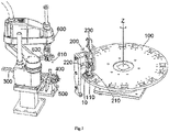
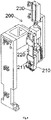
- the movable block 220 is driven to move downward to press the contact 20 received in the contact guiding slot 211 into a contact installation slot of the housing 10 in a condition where the contact guiding slot 211 of the fixing block 210 is aligned to the contact installation slot of the housing 10.
- the assembly system further comprises a rotatable table 100 configured to be rotatable about a vertical axis Z.
- the fixing device 110 is mounted on the rotatable table 100, and the rotatable table 100 is adapted to rotate the fixing device 110 to a contact assembly station where the contact installation slot (not shown) of the housing 10 fixed on the fixing device 110 is aligned to the contact guiding slot 211 of the fixing block 210 on the pressing mechanism 200.
- the contact installation slot (not shown) of the housing 10 fixed on the fixing device 110 is aligned to the contact guiding slot 211 of the fixing block 210 on the pressing mechanism 200.
- a plurality of fixing devices 110 are mounted on the rotatable table 100 around the periphery of rotatable table 100 and separated from each other.
- the rotatable table 100 is adapted to rotate the plurality of fixing devices 110 to the contact assembly station one by one.
- the pressing mechanism 200 further comprises a driving device 230 configured to drive the movable block 220 to move downward.
- the driving device 230 may comprise a motor, an air cylinder or a hydraulic cylinder.
- a plurality of contact guiding slots 211 are formed in the fixing block 210, each contact installation slot being constructed to hold one contact therein, and a plurality of contact installation slots are formed in the housing 10.
- the pressing mechanism 200 is adapted to press the plurality of contacts 20 received in the plurality of contact guiding slots 211, respectively, into the plurality of contact installation slots at one time.
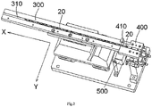
- Fig.2 is an illustrative perspective view of a contact supply mechanism, a contact positioning mechanism and a contactless sensor of the assembly system of Fig.1 ;
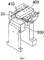
- Fig.3 is an illustrative perspective view of the contact positioning mechanism and the contactless sensor of the assembly system of Fig.1 .
- the assembly system further comprises a robot 600 adapted to grip the contact 20 and insert the gripped contact 20 into the contact guiding slot 211 of the fixing block 210.
- the assembly system further comprises a contact supply mechanism 300 configured to supply the contact 20 to be assembled.
- the assembly system further comprises a contact positioning mechanism 400 formed with a contact positioning slot 410 in which the contact 20 is adapted to be positioned.
- the contact supply mechanism 300 comprises a linear vibration guide 310 extending in a first horizontal direction X, and the contacts 20 to be assembled are adapted to be loaded in the linear vibration guide 310.
- the contact positioning slot 410 of the contact positioning mechanism 400 is located at one end of the linear vibration guide 310 and aligned to the linear vibration guide 310.
- the linear vibration guide 310 is adapted to drive the contacts 20 by vibration, so as to move the contacts 20 toward the contact positioning slot 410 of the contact positioning mechanism 400.
- the contact positioning mechanism 400 is configured to be movable in a second horizontal direction Y perpendicular to the first horizontal direction X.
- the contact positioning mechanism 400 is moved in the second horizontal direction Y and separated from the linear vibration guide 310 after the contact 20 is moved from the linear vibration guide 310 into the contact positioning slot 410.
- the assembly system further comprises a contactless sensor 500 configured to detect whether the contact 20 in the contact positioning mechanism 400 is qualified. If the contact 20 is not qualified, then the robot 600 will grip and discard the unqualified contact 20.
- the contactless sensor 500 may comprise a distance sensor, a visual sensor or an infrared sensor.
- the contactless sensor 500 may be fixed to the contact positioning mechanism 400 and moved together with the contact positioning mechanism 400 in the second horizontal direction Y.
- the contact positioning slot 410 of the contact positioning mechanism 400 is adapted to position the contact 20 in a horizontal posture.
- the robot 600 comprises a rotation mechanism 620 adapted to rotate the manipulator 610, so as to rotate the contact 20 from the horizontal posture to a vertical posture.
- the robot 600 is adapted to insert the gripped contact 20 in the vertical posture into the contact guiding slot 211 of the pressing mechanism 200.
Landscapes
- Engineering & Computer Science (AREA)
- Manufacturing & Machinery (AREA)
- Microelectronics & Electronic Packaging (AREA)
- Operations Research (AREA)
- Manufacturing Of Electrical Connectors (AREA)
- Automatic Assembly (AREA)
Claims (18)
- Montagesystem zum Einführen eines Kontaktes (20) in ein Gehäuse (10), das umfasst:eine Fixiervorrichtung (110), die zum Fixieren des Gehäuses (10) ausgeführt ist; sowieeinen Drückmechanismus (200), der zum Einsetzen des Kontaktes (20) in das Gehäuse (10) eingerichtet ist,wobei der Drückmechanismus (200) umfasst:einen Fixierblock (210), der mit einem Kontakt-Führungsschlitz (211) versehen ist, der zum Aufnehmen des Kontaktes (20) darin eingerichtet ist; undeinen beweglichen Block (220), der zum Pressen des Kontaktes (20) nach unten eingerichtet ist,wobei der bewegliche Block (220) nach unten bewegt wird, um den in dem Kontakt-Führungsschlitz (211) aufgenommenen Kontakt (20) in einem Zustand in einen Kontakt-Installationsschlitz des Gehäuses (10) hinein zu drücken, in dem der Kontakt-Führungsschlitz (211) des Fixierblocks (210) auf den Kontakt-Installationsschlitz des Gehäuses (10) ausgerichtet ist,dadurch gekennzeichnet, dass der bewegliche Block (220) beweglich an dem Fixierblock (210) angebracht ist.
- Montagesystem nach Anspruch 1, das des Weiteren umfasst:einen drehbaren Tisch (100), der so ausgeführt ist, dass er um eine vertikale Achse (Z) herum gedreht wird,wobei die Fixiervorrichtung (110) an dem drehbaren Tisch (100) angebracht ist und der drehbare Tisch (100) so eingerichtet ist, dass er die Fixiervorrichtung (110) zu einer Kontakt-Montagestation dreht, wo der Kontakt-Installationsschlitz des an der Fixiervorrichtung (110) fixierten Gehäuses (10) auf den Kontakt-Führungsschlitz (211) des Fixierblocks (210) an dem Drückmechanismus (200) ausgerichtet wird.
- Montagesystem nach Anspruch 2, wobei eine Vielzahl von Fixiervorrichtungen (110) um den Umfang des drehbaren Tisches (100) herum und voneinander getrennt an dem drehbaren Tisch (100) angebracht sind, und
der Drehtisch (100) so eingerichtet ist, dass er die Vielzahl von Fixiervorrichtungen (110) nacheinander zu der Kontakt-Montagestation dreht. - Montagesystem nach einem der Ansprüche 1 - 3, wobei der Drückmechanismus (200) des Weiteren eine Antriebsvorrichtung (230) umfasst, die so ausgeführt ist, dass sie den beweglichen Block (220) nach unten in Bewegung versetzt.
- Montagesystem nach Anspruch 4, wobei die Antriebsvorrichtung (230) einen Motor, einen Luftzylinder oder einen Hydraulikzylinder umfasst.
- Montagesystem nach einem der Ansprüche 1 - 5, wobei eine Vielzahl von Kontakt-Führungsschlitzen (211) in dem Fixierblock (210) ausgebildet sind und eine Vielzahl von Kontakt-Installationsschlitzen in dem Gehäuse (10) ausgebildet sind, und
der Drückmechanismus (200) so eingerichtet ist, dass er eine Vielzahl von Kontakten (20), die jeweils in der Vielzahl von Kontakt-Führungsschlitzen (211) aufgenommen sind, gleichzeitig in die Vielzahl von Kontakt-Installationsschlitzen hinein drückt. - Montagesystem nach einem der Ansprüche 2 - 6, das des Weiteren umfasst:
einen Roboter (600), der so eingerichtet ist, dass er den Kontakt (20) ergreift und den ergriffenen Kontakt (20) in den Kontakt-Führungsschlitz (211) des Fixierblocks (210) einführt. - Montagesystem nach Anspruch 7, das des Weiteren umfasst:
einen Kontakt-Zuführmechanismus (300), der so ausgeführt ist, dass er den zu montierenden Kontakt (20) zuführt. - Montagesystem nach Anspruch 8, das des Weiteren umfasst:
einen Kontakt-Positioniermechanismus (400), der mit einem Kontakt-Positionierschlitz (410) versehen ist, in dem der Kontakt (20) positioniert wird. - Montagesystem nach Anspruch 9, wobei der Kontakt-Zuführmechanismus (300) eine lineare Vibrations-Führungseinrichtung (310) umfasst, die sich in einer ersten horizontalen Richtung (X) erstreckt, wobei die zu montierenden Kontakte (20) in die lineare Vibrations-Führungseinrichtung (310) geladen werden;sich der Kontakt-Positionierschlitz (410) des Kontakt-Positioniermechanismus (400) an einem Ende der linearen Vibrations-Führungseinrichtung (310) befindet und auf die lineare Vibrations-Führungseinrichtung (310) ausgerichtet ist; unddie lineare Vibrations-Führungseinrichtung (310) so eingerichtet ist, dass sie die Kontakte (20) durch Vibration antreibt und die Kontakte (20) so in Richtung des Kontakt-Positionierschlitzes (410) des Kontakt-Positioniermechanismus (400) bewegt.
- Montagesystem nach Anspruch 10, wobei der Kontakt-Positioniermechanismus (400) so ausgeführt ist, dass er in einer zweiten horizontalen Richtung (Y) senkrecht zu der ersten horizontalen Richtung (X) bewegt werden kann; und
der Kontakt-Positioniermechanismus (400) in der zweiten horizontalen Richtung (Y) bewegt und von der linearen Vibrations-Führungseinrichtung (310) getrennt wird, nachdem der Kontakt (20) von der linearen Vibrations-Führungseinrichtung (310) in den Kontakt-Positionierschlitz (410) hinein bewegt worden ist. - Montagesystem nach Anspruch 11, das des Weiteren umfasst:
einen kontaktlosen Sensor (500), der so ausgeführt ist, dass er erfasst, ob der Kontakt (20) in dem Kontakt-Positioniermechanismus (400) geeignet ist. - Montagesystem nach Anspruch 12, wobei der kontaktlose Sensor (500) einen Abstandssensor, einen optischen Sensor oder einen Infrarotsensor umfasst.
- Montagesystem nach Anspruch 12, wobei der kontaktlose Sensor (500) an dem Kontakt-Positioniermechanismus (400) befestigt ist und zusammen mit dem Kontakt-Positioniermechanismus (400) in der zweiten horizontalen Richtung (Y) bewegt wird.
- Montagesystem nach Anspruch 11, wobei der Kontakt-Positionierschlitz (410) des Kontakt-Positioniermechanismus (400) so eingerichtet ist, dass er den Kontakt (20) in einer horizontalen Lage positioniert.
- Montagesystem nach Anspruch 15, wobei der Roboter (600) einen Manipulator (610) umfasst, der so eingerichtet ist, dass er den von dem Kontakt-Positioniermechanismus (400) in der horizontalen Lage positionierten Kontakt (20) ergreift.
- Montagesystem nach Anspruch 16, wobei der Roboter (600) des Weiteren einen Drehmechanismus (620) umfasst, der so eingerichtet ist, dass er den Manipulator (610) dreht, um den Kontakt (20) aus der horizontalen Lage in eine vertikale Lage zu drehen.
- Montagesystem nach Anspruch 17, wobei der Roboter (600) so eingerichtet ist, dass er den ergriffenen Kontakt (20) in der vertikalen Lage in den Kontakt-Führungsschlitz (211) des Drückmechanismus (200) einführt.
Applications Claiming Priority (1)
| Application Number | Priority Date | Filing Date | Title |
|---|---|---|---|
| CN201711007567.1A CN109713545B (zh) | 2017-10-25 | 2017-10-25 | 装配系统和装配方法 |
Publications (2)
| Publication Number | Publication Date |
|---|---|
| EP3477797A1 EP3477797A1 (de) | 2019-05-01 |
| EP3477797B1 true EP3477797B1 (de) | 2022-05-04 |
Family
ID=63965336
Family Applications (1)
| Application Number | Title | Priority Date | Filing Date |
|---|---|---|---|
| EP18201949.7A Active EP3477797B1 (de) | 2017-10-25 | 2018-10-23 | Montagesystem |
Country Status (3)
| Country | Link |
|---|---|
| US (1) | US10993360B2 (de) |
| EP (1) | EP3477797B1 (de) |
| CN (1) | CN109713545B (de) |
Families Citing this family (5)
| Publication number | Priority date | Publication date | Assignee | Title |
|---|---|---|---|---|
| CN112421342B (zh) * | 2019-08-22 | 2024-01-16 | 东莞市联晨鑫电子科技有限公司 | 射频连接器的装配方法与射频连接器安装装置 |
| CN111015212B (zh) * | 2019-12-24 | 2024-08-27 | 昆山华誉自动化科技有限公司 | 动触头组装机及其组装方法 |
| CN113118754B (zh) * | 2021-03-24 | 2022-10-14 | 江苏立讯机器人有限公司 | 一种组装设备 |
| CN115771023B (zh) * | 2022-11-24 | 2024-04-02 | 臻越自动化技术(上海)有限公司 | 一种具有检测功能的卡扣安装机构 |
| CN116505350B (zh) * | 2023-05-05 | 2023-11-10 | 扬州京柏自动化科技有限公司 | 一种插接件自动化组装设备 |
Family Cites Families (12)
| Publication number | Priority date | Publication date | Assignee | Title |
|---|---|---|---|---|
| US2829423A (en) * | 1950-10-10 | 1958-04-08 | Wade Electric Products Co | Apparatus for assembling electrical devices |
| US4967470A (en) * | 1990-04-20 | 1990-11-06 | Amp Incorporated | Alignment apparatus for positioning a connector housing during wire insertion |
| JP4001847B2 (ja) * | 2003-07-02 | 2007-10-31 | 矢崎総業株式会社 | 端子金具の誘導挿入装置 |
| JP4851349B2 (ja) * | 2007-01-04 | 2012-01-11 | 矢崎総業株式会社 | 端子挿入装置 |
| CN103415966B (zh) * | 2011-03-07 | 2016-08-17 | 日本自动机械株式会社 | 端子插入装置、线束制造装置及端子插入方法 |
| JP6002628B2 (ja) * | 2013-05-10 | 2016-10-05 | 矢崎総業株式会社 | 端子挿入装置及び端子挿入方法 |
| CN203612592U (zh) * | 2013-10-21 | 2014-05-28 | 泰科电子(上海)有限公司 | 自动供料系统和自动组装系统 |
| CN105083977B (zh) * | 2014-05-14 | 2018-04-10 | 泰科电子(上海)有限公司 | 自动配料设备 |
| CN105842794B (zh) * | 2015-01-14 | 2018-01-30 | 泰科电子(上海)有限公司 | 光纤插入系统和方法 |
| CN106475773B (zh) * | 2015-08-28 | 2019-06-14 | 泰科电子(上海)有限公司 | 自动装配系统及方法 |
| CN106129775B (zh) * | 2016-08-31 | 2018-05-04 | 东莞市本林实业有限公司 | 一种多功能连接器组装平台 |
| CN108808422B (zh) * | 2016-12-30 | 2020-06-02 | 东莞市凯勒帝数控科技有限公司 | 一种用于接口pin针组装的插针转料机构 |
-
2017
- 2017-10-25 CN CN201711007567.1A patent/CN109713545B/zh active Active
-
2018
- 2018-10-23 EP EP18201949.7A patent/EP3477797B1/de active Active
- 2018-10-24 US US16/169,511 patent/US10993360B2/en active Active
Also Published As
| Publication number | Publication date |
|---|---|
| CN109713545B (zh) | 2021-03-23 |
| EP3477797A1 (de) | 2019-05-01 |
| CN109713545A (zh) | 2019-05-03 |
| US20190124805A1 (en) | 2019-04-25 |
| US10993360B2 (en) | 2021-04-27 |
Similar Documents
| Publication | Publication Date | Title |
|---|---|---|
| EP3477797B1 (de) | Montagesystem | |
| US11276992B2 (en) | Method for electrical cabling with a cable sequence of electronic components in switchgear construction and a corresponding robot arrangement | |
| EP0989652B1 (de) | Verarbeitungsverfahren und -apparat eines Kabelendes | |
| US20080113555A1 (en) | Manufacturing apparatus for wiring harnesses and a manufacturing method for wiring harnesses | |
| US5157830A (en) | Method for automatically connecting electric conductors with contact parts to connector shells | |
| US5945635A (en) | Wire assembly apparatus and method for assembling wires | |
| CN101450485A (zh) | 工业机器人电缆导向装置 | |
| KR20160035021A (ko) | 와이어 하네스의 제조 장치 및 그 제조 방법 | |
| EP3477798B1 (de) | Montagesystem | |
| WO2014066343A1 (en) | Wire sorting fixture and method of sorting wires | |
| JP2020066067A (ja) | ロボットハンドおよびロボットシステム | |
| US20020144395A1 (en) | Method and apparatus for equipping plug housings with fitted-out cable ends of a cable | |
| EP0501392A2 (de) | Träger und dessen Herstellungsverfahren sowie dessen Verwendung | |
| CN110546829B (zh) | 向附带端子的电线的端子装配壳体的装置及向附带端子的电线的端子装配壳体的方法 | |
| EP0489558A2 (de) | Vorrichtung zum Herstellen eines elektrischen Kabelbaumes | |
| EP0881720B1 (de) | Gerät zum Anbringen eines Leitungsdurchführungspfropfens | |
| CN109997284A (zh) | 端子保持件、端子压接装置及附带端子的绞合电线的制造方法 | |
| US20150364841A1 (en) | Spring Clip and Connection Box | |
| JPH0745352A (ja) | 異種端子付テープおよび端子圧着機 | |
| CN120660247A (zh) | 用于压接自动装置的输送装置、压接自动装置、条带和带系统、输送系统、用于运行压接自动装置的方法、混合插接连接器和用于混合插接连接器的装备方法 | |
| JP5193008B2 (ja) | ハーネス接続部材用組立用具 | |
| JP3432440B2 (ja) | ハーネス取付装置及び取付方法 | |
| US11283230B2 (en) | Device, method, and system for inverse crimping | |
| US11769978B2 (en) | Assembly system | |
| CN108856399B (zh) | 折弯机 |
Legal Events
| Date | Code | Title | Description |
|---|---|---|---|
| PUAI | Public reference made under article 153(3) epc to a published international application that has entered the european phase |
Free format text: ORIGINAL CODE: 0009012 |
|
| STAA | Information on the status of an ep patent application or granted ep patent |
Free format text: STATUS: THE APPLICATION HAS BEEN PUBLISHED |
|
| AK | Designated contracting states |
Kind code of ref document: A1 Designated state(s): AL AT BE BG CH CY CZ DE DK EE ES FI FR GB GR HR HU IE IS IT LI LT LU LV MC MK MT NL NO PL PT RO RS SE SI SK SM TR |
|
| AX | Request for extension of the european patent |
Extension state: BA ME |
|
| STAA | Information on the status of an ep patent application or granted ep patent |
Free format text: STATUS: REQUEST FOR EXAMINATION WAS MADE |
|
| 17P | Request for examination filed |
Effective date: 20191031 |
|
| RBV | Designated contracting states (corrected) |
Designated state(s): AL AT BE BG CH CY CZ DE DK EE ES FI FR GB GR HR HU IE IS IT LI LT LU LV MC MK MT NL NO PL PT RO RS SE SI SK SM TR |
|
| STAA | Information on the status of an ep patent application or granted ep patent |
Free format text: STATUS: EXAMINATION IS IN PROGRESS |
|
| 17Q | First examination report despatched |
Effective date: 20200526 |
|
| GRAP | Despatch of communication of intention to grant a patent |
Free format text: ORIGINAL CODE: EPIDOSNIGR1 |
|
| STAA | Information on the status of an ep patent application or granted ep patent |
Free format text: STATUS: GRANT OF PATENT IS INTENDED |
|
| INTG | Intention to grant announced |
Effective date: 20211203 |
|
| GRAS | Grant fee paid |
Free format text: ORIGINAL CODE: EPIDOSNIGR3 |
|
| GRAA | (expected) grant |
Free format text: ORIGINAL CODE: 0009210 |
|
| STAA | Information on the status of an ep patent application or granted ep patent |
Free format text: STATUS: THE PATENT HAS BEEN GRANTED |
|
| AK | Designated contracting states |
Kind code of ref document: B1 Designated state(s): AL AT BE BG CH CY CZ DE DK EE ES FI FR GB GR HR HU IE IS IT LI LT LU LV MC MK MT NL NO PL PT RO RS SE SI SK SM TR |
|
| REG | Reference to a national code |
Ref country code: GB Ref legal event code: FG4D |
|
| REG | Reference to a national code |
Ref country code: CH Ref legal event code: EP |
|
| REG | Reference to a national code |
Ref country code: AT Ref legal event code: REF Ref document number: 1490134 Country of ref document: AT Kind code of ref document: T Effective date: 20220515 |
|
| REG | Reference to a national code |
Ref country code: DE Ref legal event code: R096 Ref document number: 602018034833 Country of ref document: DE |
|
| REG | Reference to a national code |
Ref country code: IE Ref legal event code: FG4D |
|
| REG | Reference to a national code |
Ref country code: LT Ref legal event code: MG9D |
|
| REG | Reference to a national code |
Ref country code: NL Ref legal event code: MP Effective date: 20220504 |
|
| REG | Reference to a national code |
Ref country code: AT Ref legal event code: MK05 Ref document number: 1490134 Country of ref document: AT Kind code of ref document: T Effective date: 20220504 |
|
| PG25 | Lapsed in a contracting state [announced via postgrant information from national office to epo] |
Ref country code: SE Free format text: LAPSE BECAUSE OF FAILURE TO SUBMIT A TRANSLATION OF THE DESCRIPTION OR TO PAY THE FEE WITHIN THE PRESCRIBED TIME-LIMIT Effective date: 20220504 Ref country code: PT Free format text: LAPSE BECAUSE OF FAILURE TO SUBMIT A TRANSLATION OF THE DESCRIPTION OR TO PAY THE FEE WITHIN THE PRESCRIBED TIME-LIMIT Effective date: 20220905 Ref country code: NO Free format text: LAPSE BECAUSE OF FAILURE TO SUBMIT A TRANSLATION OF THE DESCRIPTION OR TO PAY THE FEE WITHIN THE PRESCRIBED TIME-LIMIT Effective date: 20220804 Ref country code: NL Free format text: LAPSE BECAUSE OF FAILURE TO SUBMIT A TRANSLATION OF THE DESCRIPTION OR TO PAY THE FEE WITHIN THE PRESCRIBED TIME-LIMIT Effective date: 20220504 Ref country code: LT Free format text: LAPSE BECAUSE OF FAILURE TO SUBMIT A TRANSLATION OF THE DESCRIPTION OR TO PAY THE FEE WITHIN THE PRESCRIBED TIME-LIMIT Effective date: 20220504 Ref country code: HR Free format text: LAPSE BECAUSE OF FAILURE TO SUBMIT A TRANSLATION OF THE DESCRIPTION OR TO PAY THE FEE WITHIN THE PRESCRIBED TIME-LIMIT Effective date: 20220504 Ref country code: GR Free format text: LAPSE BECAUSE OF FAILURE TO SUBMIT A TRANSLATION OF THE DESCRIPTION OR TO PAY THE FEE WITHIN THE PRESCRIBED TIME-LIMIT Effective date: 20220805 Ref country code: FI Free format text: LAPSE BECAUSE OF FAILURE TO SUBMIT A TRANSLATION OF THE DESCRIPTION OR TO PAY THE FEE WITHIN THE PRESCRIBED TIME-LIMIT Effective date: 20220504 Ref country code: ES Free format text: LAPSE BECAUSE OF FAILURE TO SUBMIT A TRANSLATION OF THE DESCRIPTION OR TO PAY THE FEE WITHIN THE PRESCRIBED TIME-LIMIT Effective date: 20220504 Ref country code: BG Free format text: LAPSE BECAUSE OF FAILURE TO SUBMIT A TRANSLATION OF THE DESCRIPTION OR TO PAY THE FEE WITHIN THE PRESCRIBED TIME-LIMIT Effective date: 20220804 Ref country code: AT Free format text: LAPSE BECAUSE OF FAILURE TO SUBMIT A TRANSLATION OF THE DESCRIPTION OR TO PAY THE FEE WITHIN THE PRESCRIBED TIME-LIMIT Effective date: 20220504 |
|
| PG25 | Lapsed in a contracting state [announced via postgrant information from national office to epo] |
Ref country code: RS Free format text: LAPSE BECAUSE OF FAILURE TO SUBMIT A TRANSLATION OF THE DESCRIPTION OR TO PAY THE FEE WITHIN THE PRESCRIBED TIME-LIMIT Effective date: 20220504 Ref country code: PL Free format text: LAPSE BECAUSE OF FAILURE TO SUBMIT A TRANSLATION OF THE DESCRIPTION OR TO PAY THE FEE WITHIN THE PRESCRIBED TIME-LIMIT Effective date: 20220504 Ref country code: LV Free format text: LAPSE BECAUSE OF FAILURE TO SUBMIT A TRANSLATION OF THE DESCRIPTION OR TO PAY THE FEE WITHIN THE PRESCRIBED TIME-LIMIT Effective date: 20220504 Ref country code: IS Free format text: LAPSE BECAUSE OF FAILURE TO SUBMIT A TRANSLATION OF THE DESCRIPTION OR TO PAY THE FEE WITHIN THE PRESCRIBED TIME-LIMIT Effective date: 20220904 |
|
| PG25 | Lapsed in a contracting state [announced via postgrant information from national office to epo] |
Ref country code: SM Free format text: LAPSE BECAUSE OF FAILURE TO SUBMIT A TRANSLATION OF THE DESCRIPTION OR TO PAY THE FEE WITHIN THE PRESCRIBED TIME-LIMIT Effective date: 20220504 Ref country code: SK Free format text: LAPSE BECAUSE OF FAILURE TO SUBMIT A TRANSLATION OF THE DESCRIPTION OR TO PAY THE FEE WITHIN THE PRESCRIBED TIME-LIMIT Effective date: 20220504 Ref country code: RO Free format text: LAPSE BECAUSE OF FAILURE TO SUBMIT A TRANSLATION OF THE DESCRIPTION OR TO PAY THE FEE WITHIN THE PRESCRIBED TIME-LIMIT Effective date: 20220504 Ref country code: EE Free format text: LAPSE BECAUSE OF FAILURE TO SUBMIT A TRANSLATION OF THE DESCRIPTION OR TO PAY THE FEE WITHIN THE PRESCRIBED TIME-LIMIT Effective date: 20220504 Ref country code: DK Free format text: LAPSE BECAUSE OF FAILURE TO SUBMIT A TRANSLATION OF THE DESCRIPTION OR TO PAY THE FEE WITHIN THE PRESCRIBED TIME-LIMIT Effective date: 20220504 Ref country code: CZ Free format text: LAPSE BECAUSE OF FAILURE TO SUBMIT A TRANSLATION OF THE DESCRIPTION OR TO PAY THE FEE WITHIN THE PRESCRIBED TIME-LIMIT Effective date: 20220504 |
|
| REG | Reference to a national code |
Ref country code: DE Ref legal event code: R097 Ref document number: 602018034833 Country of ref document: DE |
|
| PLBE | No opposition filed within time limit |
Free format text: ORIGINAL CODE: 0009261 |
|
| STAA | Information on the status of an ep patent application or granted ep patent |
Free format text: STATUS: NO OPPOSITION FILED WITHIN TIME LIMIT |
|
| PG25 | Lapsed in a contracting state [announced via postgrant information from national office to epo] |
Ref country code: AL Free format text: LAPSE BECAUSE OF FAILURE TO SUBMIT A TRANSLATION OF THE DESCRIPTION OR TO PAY THE FEE WITHIN THE PRESCRIBED TIME-LIMIT Effective date: 20220504 |
|
| 26N | No opposition filed |
Effective date: 20230207 |
|
| PG25 | Lapsed in a contracting state [announced via postgrant information from national office to epo] |
Ref country code: SI Free format text: LAPSE BECAUSE OF FAILURE TO SUBMIT A TRANSLATION OF THE DESCRIPTION OR TO PAY THE FEE WITHIN THE PRESCRIBED TIME-LIMIT Effective date: 20220504 Ref country code: MC Free format text: LAPSE BECAUSE OF FAILURE TO SUBMIT A TRANSLATION OF THE DESCRIPTION OR TO PAY THE FEE WITHIN THE PRESCRIBED TIME-LIMIT Effective date: 20220504 |
|
| REG | Reference to a national code |
Ref country code: CH Ref legal event code: PL |
|
| REG | Reference to a national code |
Ref country code: BE Ref legal event code: MM Effective date: 20221031 |
|
| GBPC | Gb: european patent ceased through non-payment of renewal fee |
Effective date: 20221023 |
|
| PG25 | Lapsed in a contracting state [announced via postgrant information from national office to epo] |
Ref country code: LU Free format text: LAPSE BECAUSE OF NON-PAYMENT OF DUE FEES Effective date: 20221023 |
|
| PG25 | Lapsed in a contracting state [announced via postgrant information from national office to epo] |
Ref country code: LI Free format text: LAPSE BECAUSE OF NON-PAYMENT OF DUE FEES Effective date: 20221031 Ref country code: FR Free format text: LAPSE BECAUSE OF NON-PAYMENT OF DUE FEES Effective date: 20221031 Ref country code: CH Free format text: LAPSE BECAUSE OF NON-PAYMENT OF DUE FEES Effective date: 20221031 |
|
| PG25 | Lapsed in a contracting state [announced via postgrant information from national office to epo] |
Ref country code: BE Free format text: LAPSE BECAUSE OF NON-PAYMENT OF DUE FEES Effective date: 20221031 |
|
| PG25 | Lapsed in a contracting state [announced via postgrant information from national office to epo] |
Ref country code: IE Free format text: LAPSE BECAUSE OF NON-PAYMENT OF DUE FEES Effective date: 20221023 Ref country code: GB Free format text: LAPSE BECAUSE OF NON-PAYMENT OF DUE FEES Effective date: 20221023 |
|
| PG25 | Lapsed in a contracting state [announced via postgrant information from national office to epo] |
Ref country code: IT Free format text: LAPSE BECAUSE OF FAILURE TO SUBMIT A TRANSLATION OF THE DESCRIPTION OR TO PAY THE FEE WITHIN THE PRESCRIBED TIME-LIMIT Effective date: 20220504 |
|
| PG25 | Lapsed in a contracting state [announced via postgrant information from national office to epo] |
Ref country code: HU Free format text: LAPSE BECAUSE OF FAILURE TO SUBMIT A TRANSLATION OF THE DESCRIPTION OR TO PAY THE FEE WITHIN THE PRESCRIBED TIME-LIMIT; INVALID AB INITIO Effective date: 20181023 |
|
| PG25 | Lapsed in a contracting state [announced via postgrant information from national office to epo] |
Ref country code: CY Free format text: LAPSE BECAUSE OF FAILURE TO SUBMIT A TRANSLATION OF THE DESCRIPTION OR TO PAY THE FEE WITHIN THE PRESCRIBED TIME-LIMIT Effective date: 20220504 |
|
| PG25 | Lapsed in a contracting state [announced via postgrant information from national office to epo] |
Ref country code: MK Free format text: LAPSE BECAUSE OF FAILURE TO SUBMIT A TRANSLATION OF THE DESCRIPTION OR TO PAY THE FEE WITHIN THE PRESCRIBED TIME-LIMIT Effective date: 20220504 |
|
| PG25 | Lapsed in a contracting state [announced via postgrant information from national office to epo] |
Ref country code: MT Free format text: LAPSE BECAUSE OF FAILURE TO SUBMIT A TRANSLATION OF THE DESCRIPTION OR TO PAY THE FEE WITHIN THE PRESCRIBED TIME-LIMIT Effective date: 20220504 |
|
| PG25 | Lapsed in a contracting state [announced via postgrant information from national office to epo] |
Ref country code: BG Free format text: LAPSE BECAUSE OF FAILURE TO SUBMIT A TRANSLATION OF THE DESCRIPTION OR TO PAY THE FEE WITHIN THE PRESCRIBED TIME-LIMIT Effective date: 20220504 |
|
| PG25 | Lapsed in a contracting state [announced via postgrant information from national office to epo] |
Ref country code: BG Free format text: LAPSE BECAUSE OF FAILURE TO SUBMIT A TRANSLATION OF THE DESCRIPTION OR TO PAY THE FEE WITHIN THE PRESCRIBED TIME-LIMIT Effective date: 20220504 |
|
| PGFP | Annual fee paid to national office [announced via postgrant information from national office to epo] |
Ref country code: DE Payment date: 20240904 Year of fee payment: 7 |
|
| PG25 | Lapsed in a contracting state [announced via postgrant information from national office to epo] |
Ref country code: TR Free format text: LAPSE BECAUSE OF FAILURE TO SUBMIT A TRANSLATION OF THE DESCRIPTION OR TO PAY THE FEE WITHIN THE PRESCRIBED TIME-LIMIT Effective date: 20220504 |