EP3469245B1 - Kabelbinder - Google Patents
Kabelbinder Download PDFInfo
- Publication number
- EP3469245B1 EP3469245B1 EP17734225.0A EP17734225A EP3469245B1 EP 3469245 B1 EP3469245 B1 EP 3469245B1 EP 17734225 A EP17734225 A EP 17734225A EP 3469245 B1 EP3469245 B1 EP 3469245B1
- Authority
- EP
- European Patent Office
- Prior art keywords
- piece
- cable tie
- strap
- compensation
- tie according
- Prior art date
- Legal status (The legal status is an assumption and is not a legal conclusion. Google has not performed a legal analysis and makes no representation as to the accuracy of the status listed.)
- Active
Links
Images



Classifications
-
- F—MECHANICAL ENGINEERING; LIGHTING; HEATING; WEAPONS; BLASTING
- F16—ENGINEERING ELEMENTS AND UNITS; GENERAL MEASURES FOR PRODUCING AND MAINTAINING EFFECTIVE FUNCTIONING OF MACHINES OR INSTALLATIONS; THERMAL INSULATION IN GENERAL
- F16L—PIPES; JOINTS OR FITTINGS FOR PIPES; SUPPORTS FOR PIPES, CABLES OR PROTECTIVE TUBING; MEANS FOR THERMAL INSULATION IN GENERAL
- F16L33/00—Arrangements for connecting hoses to rigid members; Rigid hose-connectors, i.e. single members engaging both hoses
- F16L33/02—Hose-clips
- F16L33/035—Hose-clips fixed by means of teeth or hooks
-
- F—MECHANICAL ENGINEERING; LIGHTING; HEATING; WEAPONS; BLASTING
- F16—ENGINEERING ELEMENTS AND UNITS; GENERAL MEASURES FOR PRODUCING AND MAINTAINING EFFECTIVE FUNCTIONING OF MACHINES OR INSTALLATIONS; THERMAL INSULATION IN GENERAL
- F16L—PIPES; JOINTS OR FITTINGS FOR PIPES; SUPPORTS FOR PIPES, CABLES OR PROTECTIVE TUBING; MEANS FOR THERMAL INSULATION IN GENERAL
- F16L33/00—Arrangements for connecting hoses to rigid members; Rigid hose-connectors, i.e. single members engaging both hoses
- F16L33/02—Hose-clips
-
- A—HUMAN NECESSITIES
- A61—MEDICAL OR VETERINARY SCIENCE; HYGIENE
- A61M—DEVICES FOR INTRODUCING MEDIA INTO, OR ONTO, THE BODY; DEVICES FOR TRANSDUCING BODY MEDIA OR FOR TAKING MEDIA FROM THE BODY; DEVICES FOR PRODUCING OR ENDING SLEEP OR STUPOR
- A61M39/00—Tubes, tube connectors, tube couplings, valves, access sites or the like, specially adapted for medical use
- A61M39/10—Tube connectors; Tube couplings
- A61M39/12—Tube connectors; Tube couplings for joining a flexible tube to a rigid attachment
-
- B—PERFORMING OPERATIONS; TRANSPORTING
- B65—CONVEYING; PACKING; STORING; HANDLING THIN OR FILAMENTARY MATERIAL
- B65D—CONTAINERS FOR STORAGE OR TRANSPORT OF ARTICLES OR MATERIALS, e.g. BAGS, BARRELS, BOTTLES, BOXES, CANS, CARTONS, CRATES, DRUMS, JARS, TANKS, HOPPERS, FORWARDING CONTAINERS; ACCESSORIES, CLOSURES, OR FITTINGS THEREFOR; PACKAGING ELEMENTS; PACKAGES
- B65D63/00—Flexible elongated elements, e.g. straps, for bundling or supporting articles
- B65D63/10—Non-metallic straps, tapes, or bands; Filamentary elements, e.g. strings, threads or wires; Joints between ends thereof
- B65D63/1018—Joints produced by application of integral securing members, e.g. buckles, wedges, tongue and slot, locking head and teeth or the like
-
- B—PERFORMING OPERATIONS; TRANSPORTING
- B65—CONVEYING; PACKING; STORING; HANDLING THIN OR FILAMENTARY MATERIAL
- B65D—CONTAINERS FOR STORAGE OR TRANSPORT OF ARTICLES OR MATERIALS, e.g. BAGS, BARRELS, BOTTLES, BOXES, CANS, CARTONS, CRATES, DRUMS, JARS, TANKS, HOPPERS, FORWARDING CONTAINERS; ACCESSORIES, CLOSURES, OR FITTINGS THEREFOR; PACKAGING ELEMENTS; PACKAGES
- B65D63/00—Flexible elongated elements, e.g. straps, for bundling or supporting articles
- B65D63/10—Non-metallic straps, tapes, or bands; Filamentary elements, e.g. strings, threads or wires; Joints between ends thereof
- B65D63/1018—Joints produced by application of integral securing members, e.g. buckles, wedges, tongue and slot, locking head and teeth or the like
- B65D63/1027—Joints produced by application of integral securing members, e.g. buckles, wedges, tongue and slot, locking head and teeth or the like the integral securing member being formed as a female and male locking member, e.g. locking head and locking teeth, or the like
-
- H—ELECTRICITY
- H02—GENERATION; CONVERSION OR DISTRIBUTION OF ELECTRIC POWER
- H02G—INSTALLATION OF ELECTRIC CABLES OR LINES, OR OF COMBINED OPTICAL AND ELECTRIC CABLES OR LINES
- H02G3/00—Installations of electric cables or lines or protective tubing therefor in or on buildings, equivalent structures or vehicles
- H02G3/30—Installations of cables or lines on walls, floors or ceilings
- H02G3/32—Installations of cables or lines on walls, floors or ceilings using mounting clamps
-
- B—PERFORMING OPERATIONS; TRANSPORTING
- B65—CONVEYING; PACKING; STORING; HANDLING THIN OR FILAMENTARY MATERIAL
- B65D—CONTAINERS FOR STORAGE OR TRANSPORT OF ARTICLES OR MATERIALS, e.g. BAGS, BARRELS, BOTTLES, BOXES, CANS, CARTONS, CRATES, DRUMS, JARS, TANKS, HOPPERS, FORWARDING CONTAINERS; ACCESSORIES, CLOSURES, OR FITTINGS THEREFOR; PACKAGING ELEMENTS; PACKAGES
- B65D2563/00—Flexible elongated elements, e.g. straps for bundling or supporting atricles
- B65D2563/10—Non-metallic straps, tapes or bands; Filamentary elements, e.g. strings, threads, wires; Joints between ends thereof
- B65D2563/101—Details of non-metallic straps, tapes or bands
- B65D2563/108—Appendages formed with/on the strap for purposes other than joining, releasing or bundling, e.g. for fixing the strap to a wall, label plates
Definitions
- the invention relates to a cable tie and a set with such a cable tie.
- Cable ties are also known as cable ties or ratchet tape and are a universal, quick-to-use and inexpensive connecting element.
- Cable ties were originally developed to secure various cables and entire cable harnesses to each other or to other objects. However, cable ties are also used in the construction industry for temporary assembly, as packaging aids or in police practice to tie people up.
- the invention also relates to special cable ties with molded fastening elements such as adhesive bases, plug-in anchors or lamella feet, such as those used in the automotive sector.
- Cable ties according to the invention are made from plastics, in particular from PA 6.6 or PVC.
- Polyamide 6.6 also known as Nylon ® , has proven to be particularly beneficial for cable ties.
- the cable ties can also be made from other materials, such as polyurethane, POM, ABS, PP, PE, PC, PEEK, other plastics, metal, cast aluminum and even stainless steel.
- Reusable cable ties can be opened again by unlocking them and used multiple times.
- the invention relates to all such cable ties and in particular to the use of cable ties for fastening a hose to a piece of pipe.
- This attachment is widely used in medical technology to attach lines for liquids, such as blood or gases, to a hose connector, i.e. a pipe or a pipe socket.
- the hoses made of flexible material are pressed onto the pipe section using the cable tie in such a way that a tight connection is created.
- the tubing material can shrink slightly or lose its elastic properties due to aging or sterilization. This reduces the contact pressure between the hose and the pipe section and this can lead to leakage problems.
- the first leaks usually occur in the area of the head of the cable tie, where the cable tie does not lie flat against the hose. It was therefore proposed to shape the cable tie head in such a way that the cable tie rests on the hose over as large a circumferential surface area as possible.
- Cable ties with a head piece and a tab that can be pushed into the head piece and fixed in place, with a compensating piece attached to the tab are, for example, from the EP 2 247 882 B1 known.
- the invention is therefore based on the object of further developing a cable tie in such a way that it provides a secure contact pressure which deforms an object pressed together by the cable tie as evenly as possible around the circumference.
- the compensation piece has a wedge-shaped cross section with two long legs and a short base in the plane of the boundary of the cavity.
- the two long legs can thus form a wedge between the head piece and the enclosed cavity, while the short base makes it easier to move the compensation piece on the tab.
- the tab then extends transversely to the long legs, can be moved in an opening in the compensation piece and then through the opening in the head piece.
- a surface forming a long leg is designed to be flat as a contact for the head piece. This creates a contact surface that also allows the surfaces to be moved slightly relative to one another.
- Such compensation pieces can be produced inexpensively and can be combined with known cable ties. This makes it possible, in particular, to combine inexpensive, injection-molded standard cable ties with an individual compensation piece that is optimally adapted to a specific application through its shape, choice of material and/or color.
- the compensation piece can be positioned anywhere on the tab of the cable tie. When using the cable tie, it rests against the head piece of the cable tie.
- the two-part design of the head piece and the compensation piece means that the compensation piece is optimally positioned when the cable tie is tightened and in the event of vibrations or a change in shape of the materials, the position of the compensation piece on the tab or relative to the head piece can change slightly. This means that the contact pressure can be maintained for longer.
- the compensating piece has a concave surface on its side assigned to the cavity.
- a concave surface can fill the "gusset space" between the headpiece and the tab to increase the contact surface.
- a flat surface or a structured surface can be provided instead of a concave surface, as an elastic tubing material adapts to the shape of the surface.
- the concave surface of the compensation piece can approximately correspond to the radius of the circular cavity.
- a deviation of the radii of the compensation piece from the radius of the bounded cavity of a maximum of +/- 30% and preferably of a maximum of +/- 10% and particularly preferably of a maximum of +/- 1% means.
- a particularly common use in medical technology is the attachment of tubes with a diameter of 3 8th Customs and 1 4 Customs service. Therefore, it is suggested that the concave surface is approximately the surface of a hose with a diameter of 3 8th customs or 1 4 Inch corresponds.
- the concave surface adjoins the tab on the one hand and the head piece on the other.
- a step for example 0.5 mm to 5.0 mm, can be provided either on one of these sides or on both sides.
- This shoulder makes the production of the compensation piece easier and the shoulder, which can also be rounded, avoids sharp edges that could damage a hose if used improperly as a cutting surface.
- the handling of the compensation piece is improved if the transition from a surface forming a long leg to a surface forming the base is rounded. Both transition surfaces are preferably slightly rounded.
- the contact surface is designed in such a way that the surfaces are centered relative to one another during contact becomes. This is achieved, for example, by a concave surface that fits into a convex surface.
- a structure can be provided on this contact surface between the head piece and the compensation piece, which limits the mobility of the surfaces relative to one another.
- the compensating piece has a rectangular slot for receiving the tab, the longer side of which corresponds to the width of the tab, so that it can be moved on the tab and does not slip loosely on the tab.
- the compensation piece can therefore be moved by applying slight pressure on the tab and does not slip off the tab independently due to its own weight.
- the compensation piece has a rectangular slot for receiving the tab, the shorter or longer side of which has a resilient or elastic contact surface, so that this contact surface presses against the tab. This ensures that even if the compensation piece is used repeatedly, the compensation piece does not accidentally slip off the tab.
- the compensation piece can have a stop that interacts with a counterpart on the tab. This stop ensures that the compensation piece can only be pushed onto the tab up to a certain position. This stop can, for example, also be part of a locking device in the compensation piece, so that the position on the stop can be changed noticeably.
- the locking device in the head piece can give way or the object surrounded by the tab, such as a hose line, can shrink, it is advantageous if a fixed contact pressure is maintained in this case too.
- the compensation piece is or has an elastic part that deforms under pressure. This can, for example, ensure that the compensation piece continues to rest on the hose even when the diameter of the hose shrinks by approximately one or more millimeters.
- the elasticity does not have to be provided on the tab or on the head piece, but rather an elasticity on a part of the compensation piece or a Compensating pieces made of an elastic material can provide the necessary elasticity to maintain sufficient contact pressure from the tab to the material surrounded by the tab.
- the compensation piece can have an elastic contact surface, in particular on the side facing the cavity, which forms a pressure cushion.
- the compensation piece can also be made of a more elastic material than the head piece with the tab in order to achieve the spring effect.
- the elasticity can also be achieved through a special structure on the contact surfaces of the tab.
- serrations or corrugations can be provided that bend elastically under pressure.
- the compensation piece can be manufactured as an injection molded part and preferably as a two-component injection molded part.
- the two-component injection molded part makes it possible to produce functionally different areas, such as resilient contact surfaces and stable shaping areas, from different materials during an injection molding process.
- the use of a 3D printing process is suggested for the production of smaller quantities and for multi-component production.
- the shorter leg can have a label or an imprint.
- different compensation pieces can be made in different colors.
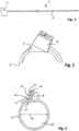
- the Indian Figure 1 Cable tie 1 shown consists of a head piece 2 and a tab 3.
- FIG. 2 In the exemplary embodiment shown, there is a compensating piece 5 on the head piece 4 and the tab 6 is pulled through the compensating piece 5 and the head piece 4.
- the exemplary embodiment shows a similar training Figure 3 .
- the compensation piece 7 rests on the head piece 8 and the tab 9 is threaded through an opening 10 in the compensation piece 7 and through the head piece 8.
- a toothing 11 on the head piece 8 cooperates with a toothing 12 on the tab 9 to hold the end 13 of the tab 9 in the head 8.
- edge 14 on the compensation piece 7 can interact with the teeth 12 on the tab 9.
- this is not necessary for the function of the invention.
- the cavity 15 delimited by the tab 9 is circular with a diameter 16 of 3 8th Customs service.
- the opposite surface 19 is concave with a radius 20 of, for example, 7.0 cm.
- the contact surface 21 facing the cavity 15 has a length 22 of 4.6 mm and a radius 23 of 8.3 cm. A height of 0.5 mm is provided as a paragraph 24 on both sides of the contact surface 21.
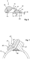
- the Figure 7 shows the interaction of the head piece 8 and the tab 9 with a compensating piece 25, which has a flexible contact surface 26, which is preferably elastic.
- the flexibility ensures a flat contact, for example on a piece of hose (not shown) arranged in the cavity 15, and elasticity counteracts a reduction in the contact pressure when the tab 9 is stretched or the hose piece shrinks.
- An enlarged labeling area 27 and an additional contact surface 28 of the compensating piece 25 on the head piece 8 is achieved by the projection 29 on the compensating piece.
- a flexible and preferably elastic surface can be provided in order to exert sufficient long-term pressure on the component (not shown) surrounded by the cable tie.
- These flexible contact surfaces can also be designed as a shoulder.
- the compensation piece 25 can, for example, have a height 31 of 3.5 mm, a length 32 of 9.1 mm and a width B of 7 mm.
- the wedge-shaped cross section is formed by two long legs 33, 34 and a short base 35.
- transition 36 from the long leg 33 to the short base 35 and the transition 37 from the long leg 34 to the short base 35 are each rounded.
- the contact surface 30 of the long leg 33 for contact with the head piece 8, however, is flat.
- the compensating piece 25 has a slot 38 whose longer side 39 corresponds to the width 40 of the tab 9 in the exemplary embodiment with a width B 'of 5.5 mm, so that the compensating piece 25 can be moved on the tab 9 and not slips loosely from the tab 9.
- the shorter side 41 of the slot 38 has an elastic contact surface which presses against the tab 9 and thereby forms little resistance when the compensating piece 25 is moved on the tab 9.
- Edge 14 shown forms a stop 42 on a toothed outer surface 12 of the tab 9 and acts as a counterpart with the tab 9.
- the Figure 12 shows an elastic part 43 on the compensating piece 44, which can deform under pressure and ensures that the compensating piece 44 is in good contact with an object delimited by the tab 9.
- a compensating piece 45 with a dotted elevation 46 as a preferably elastic contact surface of the compensating piece 45 on a head 8 of the cable tie is in Figure 13 shown.
- the Figure 14 shows a compensation piece 47 with an enlarged contact surface 48 on the short base of the compensation piece. This area is suitable for writing or attaching a label.
Landscapes
- Engineering & Computer Science (AREA)
- Health & Medical Sciences (AREA)
- General Engineering & Computer Science (AREA)
- Mechanical Engineering (AREA)
- Heart & Thoracic Surgery (AREA)
- Life Sciences & Earth Sciences (AREA)
- General Health & Medical Sciences (AREA)
- Veterinary Medicine (AREA)
- Pulmonology (AREA)
- Anesthesiology (AREA)
- Biomedical Technology (AREA)
- Hematology (AREA)
- Public Health (AREA)
- Animal Behavior & Ethology (AREA)
- Structural Engineering (AREA)
- Architecture (AREA)
- Civil Engineering (AREA)
- Package Frames And Binding Bands (AREA)
- Joints That Cut Off Fluids, And Hose Joints (AREA)
- Supports For Pipes And Cables (AREA)
- Clamps And Clips (AREA)
- Surgical Instruments (AREA)
- Superconductors And Manufacturing Methods Therefor (AREA)
- Insulated Conductors (AREA)
Description
- Die Erfindung betrifft einen Kabelbinder und ein Set mit einem derartigen Kabelbinder.
- Kabelbinder werden auch als Kabelband oder Ratsch-Band bezeichnet und bilden ein universell einsetzbares, schnell zu verwendendes und preisgünstiges Verbindungselement.
- Ursprünglich wurden Kabelbinder dafür entwickelt, verschiedene Kabel und ganze Kabelbäume aneinander oder an anderen Gegenständen zu fixieren. Kabelbinder werden jedoch auch im Baugewerbe zur provisorischen Montage, als Verpackungshilfsmittel oder in der polizeilichen Praxis zur Fesselung von Menschen verwendet. Die Erfindung betrifft auch spezielle Kabelbinder mit angespritzten Befestigungselementen wie Klebesockeln, Steckankern oder Lamellenfüßen, wie sie beispielsweise im Automobilbereich verwendet werden.
- Erfindungsgemäße Kabelbinder werden aus Kunststoffen, insbesondere aus PA 6.6 oder PVC gefertigt. Polyamid 6.6, das auch als Nylon® bekannt ist, hat sich für Kabelbinder als besonders vorteilhaft herausgestellt. Die Kabelbinder können jedoch auch aus anderen Materialien, wie beispielsweise Polyurethan, POM, ABS, PP, PE, PC, PEEK, anderen Kunststoffen, Metall, Aluminiumguss bis hin zu Edelstahl hergestellt werden.
- Bei Einwegkabelbindern wird durch eine Innen- oder Außenverzahnung erreicht, dass sich der Kabelbinder nicht mehr öffnen lässt. Er kann normalerweise nur durch Zerstörung wieder geöffnet werden. Bei Kabelbindern mit einer Sperrzunge aus Kunststoff ist es meist möglich, diese mit einer Nadel zu entriegeln und die Schlaufe so wieder zu öffnen. Um Kabelbinder mit einer besonders hohen Zugkraft herzustellen, wird in den Kopf eine Metallzunge eingearbeitet, die es ermöglicht, dass der Kabelbinder durch Einschneiden der Zunge in den Kabelbinderkörper verschließt.
- Mehrwegkabelbinder können durch eine Entriegelung wieder geöffnet und so mehrfach verwendet werden. Daneben gibt es auch Kabelbinder mit offenem Binderkopf, Doppelkopf-Kabelbinder und Kabelbinder mit besonderem Beschriftungsfeld.
- Die Erfindung betrifft alle derartigen Kabelbinder und insbesondere den Einsatz von Kabelbindern zur Befestigung eines Schlauches an einem Rohrstück. Diese Befestigung ist in der Medizintechnik weit verbreitet, um Leitungen für Flüssigkeiten, wie insbesondere Blut oder Gase, an einem Schlauchkonnektor, d.h. einem Rohr oder einem Rohrstutzen zu befestigen. Dabei werden die aus flexiblem Material hergestellten Schläuche mittels des Kabelbinders derart an das Rohrstück gepresst, dass eine dichte Verbindung entsteht.
- Insbesondere bei diesem Einsatzgebiet entsteht das Problem, dass das Schlauchmaterial durch Alterung oder Sterilisation geringfügig schrumpfen kann oder seine elastischen Eigenschaften verliert. Dadurch verringert sich der Anpressdruck zwischen dem Schlauch und dem Rohrstück und dies kann zu Dichtigkeitsproblemen führen. In der Praxis entstehen die ersten Undichtheiten meistens im Bereich des Kopfes des Kabelbinders, in dem der Kabelbinder nicht flächig am Schlauch anliegt. Daher wurde vorgeschlagen, den Kabelbinderkopf so zu formen, dass der Kabelbinder auf einem möglichst großen Umfangsflächenbereich am Schlauch anliegt.
- Diese Kabelbinder haben jedoch den Nachteil, dass für jeden Schlauchdurchmesser, ein spezieller Kabelbinder bereitgestellt werden muss. Dadurch steigt der Aufwand für die Herstellung eines einzelnen Kabelbinders und für die meist im Spritzgussverfahren hergestellten Kabelbinder, müssen unterschiedliche Formen bereitgestellt werden.
- Kabelbinder mit einem Kopfstück und einer Lasche, die in das Kopfstück geschoben werden kann und sich dabei fixiert, wobei ein Ausgleichsstück an der Lasche befestigt ist, sind beispielsweise aus der
EP 2 247 882 B1 bekannt. - Der Erfindung liegt daher die Aufgabe zugrunde, einen Kabelbinder derart weiterzuentwickeln, dass er einen sicheren Anpressdruck bereitstellt, der einen durch den Kabelbinder zusammen gepressten Gegenstand möglichst gleichmäßig am Umfang verformt.
- Diese Aufgabe wird mit einem Kabelbinder mit den Merkmalen des Patentanspruchs 1 gelöst.
- Erfindungsgemäß wird somit vorgeschlagen, einen bekannten Kabelbinder mit einem Ausgleichsstück zu kombinieren, das auf den Kabelbinder aufgefädelt wird und das eine einen langen Schenkel bildende Fläche aufweist, die als Anlage für das Kopfstück plan ausgebildet ist. Dieses Ausgleichsstück erlaubt es einerseits, in großen Stückzahlen hergestellte bekannte billige Kabelbinder zu verwenden, und andererseits, einen Kabelbinder bereitzustellen, der optimal an einen speziellen Einsatzzweck angepasst ist.
- Das Ausgleichsstück weist in der Ebene der Umgrenzung des Hohlraumes einen keilförmigen Querschnitt mit zwei langen Schenkeln und einer kurzen Basis auf. Die zwei langen Schenkel können somit einen Keil zwischen dem Kopfstück und dem umschlossenen Hohlraum bilden, während die kurze Basis es erleichtert, das Ausgleichsstück auf der Lasche zu verschieben. Die Lasche erstreckt sich dann quer zu den langen Schenkeln, verschiebbar in einem Durchbruch im Ausgleichsstück und dann durch die Öffnung im Kopfstück.
- Dabei ist eine einen langen Schenkel bildende Fläche als Anlage für das Kopfstück plan ausgebildet. Dadurch wird eine Anlagefläche gebildet, die auch eine geringfügige Verschieblichkeit der Flächen zueinander ermöglicht.
- Derartige Ausgleichsstücke sind kostengünstig herstellbar und mit bekannten Kabelbindern kombinierbar. Dies ermöglicht es insbesondere, günstige, im Spritzgussverfahren hergestellte Standardkabelbinder mit einem individuellen Ausgleichsstück zu kombinieren, das durch die Formgebung, die Materialwahl und/oder die Farbe optimal an einen speziellen Einsatzzweck angepasst ist.
- Das Ausgleichsstück kann an einer beliebigen Stelle auf der Lasche des Kabelbinders positioniert werden. Es liegt bei der Verwendung des Kabelbinders am Kopfstück des Kabelbinders an. Die Zweiteiligkeit von Kopfstück und Ausgleichsstück führt dazu, dass das Ausgleichsstück beim Anziehen des Kabelbinders optimal positioniert wird und bei Erschütterungen oder einer Formveränderung der Materialien, sich die Position des Ausgleichsstücks auf der Lasche oder relativ zum Kopfstück geringfügig verändern kann. Dadurch kann der Anpressdruck länger erhalten bleiben.
- Vorteilhafte Ausgestaltungen sind Gegenstand der Unteransprüche.
- Insbesondere für das Anpressen eines Schlauches an einem Rohrstück wird vorgeschlagen, dass das Ausgleichsstück, an seiner dem Hohlraum zugeordneten Seite, eine konkave Oberfläche aufweist. Eine derartige konkave Oberfläche kann den "Zwickelraum" zwischen Kopfstück und Lasche ausfüllen, um die Anlagefläche zu vergrößern. Je nach Einsatzzweck können an Stelle einer konkaven Oberfläche auch eine plane Fläche oder eine strukturierte Oberfläche vorgesehen werden, da sich ein elastisches Schlauchmaterial an die Form der Oberfläche anpasst.
- Wenn die Lasche einen kreisförmigen Hohlraum umgrenzt, kann die konkave Oberfläche des Ausgleichsstücks etwa dem Radius des kreisförmigen Hohlraumes entsprechen. Etwa heißt in diesem Zusammenhang, eine Abweichung der Radien des Ausgleichsstücks vom Radius des umgrenzten Hohlraumes von maximal +/- 30 % und vorzugsweise von maximal +/- 10 % und besonders bevorzugt von maximal +/- 1 %.
- Ein in der Medizintechnik besonders häufiger Einsatzzweck liegt in der Befestigung von Schläuchen mit einem Durchmesser von


- Die konkave Oberfläche grenzt auf ihrer dem Hohlraum zugewandten Seite einerseits an die Lasche und andererseits an das Kopfstück an. Ein Absatz, der beispielsweise 0,5 mm bis 5,0 mm aufweist, kann entweder auf einer dieser Seiten oder auf beiden Seiten vorgesehen sein. Dieser Absatz erleichtert die Fertigung des Ausgleichsstücks und durch den Absatz, der auch gerundet ausgebildet werden kann, werden scharfe Kanten vermieden, die bei unsachgemäßer Verwendung als Schneidefläche einen Schlauch beschädigen könnten.
- Die Handhabbarkeit des Ausgleichsstückes wird verbessert, wenn der Übergang von einer einen langen Schenkel bildenden Fläche zu einer die Basis bildenden Fläche abgerundet ist. Vorzugsweise sind beide Übergangsflächen leicht abgerundet.
- Eine nicht beanspruchte Ausführungsform sieht vor, dass die Anlagefläche so ausgebildet ist, dass während der Anlage eine Zentrierung der Flächen zueinander bewirkt wird. Dies wird beispielsweise durch eine konkave Fläche erreicht, die in eine konvexe Fläche passend eingreift. Außerdem kann an dieser Anlagefläche zwischen dem Kopfstück und dem Ausgleichsstück eine Struktur vorgesehen sein, die die Verschieblichkeit der Flächen relativ zueinander einschränkt.
- Ein leichtes Auffädeln des Ausgleichsstückes auf die Lasche wird dadurch erzielt, dass das Ausgleichsstück einen rechteckigen Schlitz für die Aufnahme der Lasche aufweist, dessen längere Seite der Breite der Lasche entspricht, sodass es auf der Lasche verschiebbar ist und nicht lose auf der Lasche rutscht. Das Ausgleichsstück ist somit mittels eines leichten Druckes auf der Lasche verschiebbar und rutscht durch sein Eigengewicht nicht selbstständig von der Lasche.
- Besonders vorteilhaft ist es, wenn das Ausgleichsstück einen rechteckigen Schlitz für die Aufnahme der Lasche aufweist, dessen kürzere oder längere Seite eine federnd oder elastisch ausgebildete Anlagefläche aufweist, sodass diese Anlagefläche gegen die Lasche drückt. Dies stellt sicher, dass auch bei wiederholter Verwendung des Ausgleichsstückes, das Ausgleichsstück nicht unbeabsichtigt von der Lasche rutscht.
- Das Ausgleichsstück kann einen Anschlag aufweisen, der mit einem Gegenstück an der Lasche zusammenwirkt. Dieser Anschlag sorgt dafür, dass das Ausgleichsstück nur bis zu einer bestimmten Position auf die Lasche aufgeschoben werden kann. Dieser Anschlag kann beispielsweise auch Teil einer Rasteinrichtung im Ausgleichsstück sein, sodass die Position am Anschlag fühlbar verändert werden kann.
- Da sich im Laufe der Zeit die Lasche des Kabelbinders verlängern kann, die Rasteinrichtung im Kopfstück nachgeben kann oder der von der Lasche umgebene Gegenstand, wie beispielsweise eine Schlauchleitung schrumpfen kann, ist es vorteilhaft, wenn auch in diesem Fall ein fester Anpressdruck erhalten bleibt. Dies wird dadurch erreicht, dass das Ausgleichsstück ein elastisches Teil ist oder aufweist, das sich unter Druck verformt. Dadurch kann beispielsweise erreicht werden, dass das Ausgleichsstück auch bei einem um etwa einen oder mehrere Millimeter im Durchmesser schrumpfenden Schlauch weiterhin am Schlauch anliegt. Somit muss die Elastizität nicht an der Lasche oder am Kopfstück vorgesehen sein, sondern eine Elastizität an einem Teil des Ausgleichsstückes oder ein Ausgleichsstück aus einem elastischen Material, können die notwendige Elastizität bereitstellen, um einen ausreichenden Anpressdruck von der Lasche an das von der Lasche umgebenen Material aufrechtzuerhalten.
- Das Ausgleichsstück kann hierfür insbesondere an der dem Hohlraum zugewandten Seite eine elastische Anlagefläche aufweisen, die ein Druckpolster bildet. Das Ausgleichsstück kann jedoch auch aus einem elastischeren Material als das Kopfstück mit der Lasche ausgebildet sein, um die Federwirkung zu erzielen.
- Die Elastizität kann auch durch eine spezielle Struktur an den Anlageflächen der Lasche erzielt werden. Hierfür können beispielsweise Zacken oder Riffelungen vorgesehen werden, die sich auf Druck elastisch verbiegen.
- Um einen Kabelbinder für spezielle Schlauchdurchmesser optimiert herzustellen, wird vorgeschlagen, ein Set aus einem derartigen Kabelbinder und einem Schlauchstück bereitzustellen oder spezielle Schlauchstücke mit einem speziell auf sie abgestimmten Kabelbinder mit Ausgleichsstück anzubieten.
- Das Ausgleichsstück kann als Spritzgussteil und vorzugsweise als Zweikomponentenspritzgussteil hergestellt sein. Das Zweikomponentenspritzgussteil ermöglicht es, funktional unterschiedliche Bereiche, wie federnde Anlageflächen und stabile Formgebungsbereiche während eines Spritzgussvorganges aus unterschiedlichem Material herzustellen. Für die Herstellung von kleineren Stückzahlen und für die Multikomponenten-Herstellung wird die Verwendung eines 3D-Druckverfahrens vorgeschlagen.
- Bei einem im Querschnitt keilförmigen Ausgleichsstück kann der kürzere Schenkel ein Etikett oder einen Aufdruck aufweisen. Außerdem können unterschiedliche Ausgleichsstücke in unterschiedlichen Farben hergestellt werden.
- Unterschiedliche Ausführungsvarianten an Kabelbindern und Ausgleichsstücken sind in der Zeichnung dargestellt und werden im Folgenden näher erläutert. Es zeigt
- Figur 1
- schematisch einen Schnitt durch einen bekannten Kabelbinder,
- Figur 2
- eine perspektivische Ansicht eines Kabelbinders mit Ausgleichsstück,
- Figur 3
- einen Schnitt durch einen Kabelbinder mit Ausgleichsstück,
- Figur 4
- eine erste perspektivische Ansicht des in
Figur 3 gezeigten Kabelbinders, - Figur 5
- eine zweite perspektivische Ansicht des in
Figur 3 gezeigten Kabelbinders, - Figur 6
- das in
Figur 3 gezeigte Ausgleichsstück als Detail, - Figur 7
- teilweise geschnitten einen Kabelbinder mit einem Ausgleichsstück, das eine flexible Anlagefläche aufweist,
- Figur 8
- eine Vorderansicht auf das in
Figur 7 gezeigte Ausgleichsstück, - Figur 9
- eine Rückansicht des in
Figur 7 gezeigten Ausgleichsstückes, - Figur 10
- eine Seitenansicht des in
Figur 7 gezeigten Ausgleichsstückes, - Figur 11
- eine Draufsicht auf das in
Figur 7 gezeigte Ausgleichsstück, - Figur 12
- eine Ansicht eines Schnittes durch das in
Figur 7 gezeigte Ausgleichsstück, - Figur 13
- eine perspektivische Ansicht eines Ausgleichsstückes gemäß
Figur 7 mit angedeuteter elastischer Auflage und - Figur 14
- ein Ausgleichsstück gemäß
Figur 7 mit angedeuteter bedruckbarer Platte. - Der in der
Figur 1 gezeigte Kabelbinder 1 besteht aus einem Kopfstück 2 und einer Lasche 3. - Bei dem in
Figur 2 gezeigtem Ausführungsbeispiel liegt am Kopfstück 4 ein Ausgleichsstück 5 an und die Lasche 6 ist durch das Ausgleichsstück 5 und das Kopfstück 4 gezogen. Eine ähnliche Ausbildung zeigt das Ausführungsbeispiel gemäßFigur 3 . Hier liegt das Ausgleichsstück 7 am Kopfstück 8 an und die Lasche 9 ist durch eine Öffnung 10 im Ausgleichsstück 7 und durch das Kopfstück 8 gefädelt. Eine Verzahnung 11 am Kopfstück 8 wirkt mit einer Verzahnung 12 an der Lasche 9 zusammen, um das Ende 13 der Lasche 9 im Kopf 8 zu halten. - Außerdem kann die Kante 14 am Ausgleichsstück 7 mit der Verzahnung 12 an der Lasche 9 zusammenwirken. Dies ist jedoch für die Funktion der Erfindung nicht notwendig.
- Bei dem in
Figur 3 gezeigten Ausführungsbeispiel ist der von der Lasche 9 umgrenzte Hohlraum 15 kreisförmig mit einem Durchmesser 16 von
Figur 6 das Ausgleichsstück 7 mit einer konkav oder konvex ausgebildeten äußeren Anlagefläche 17 am Durchlass 10 mit einem Radius 18 von beispielsweise 10,7 cm. Die gegenüberliegende Fläche 19 ist konkav mit einem Radius 20 von beispielsweise 7,0 cm ausgebildet. Die dem Hohlraum 15 zugewandte Anlagefläche 21 hat eine Länge 22 von 4,6 mm und einen Radius 23 von 8,3 cm. Als Absatz 24 ist beidseitig der Anlagefläche 21 eine Höhe von 0,5 mm vorgesehen. - Die
Figur 7 zeigt das Zusammenwirken des Kopfstückes 8 und der Lasche 9 mit einem Ausgleichsstück 25, das eine flexible Anlagefläche 26 aufweist, die vorzugsweise elastisch ausgebildet ist. Die Flexibilität sorgt für eine flächige Anlage, beispielsweise an einem im Hohlraum 15 angeordneten Schlauchstück (nicht gezeigt) und eine Elastizität wirkt einer Verringerung des Anpressdruckes bei einer Dehnung der Lasche 9 oder einem Schrumpfen des Schlauchstückes entgegen. - Eine vergrößerte Beschriftungsfläche 27 und eine zusätzliche Anlagefläche 28 des Ausgleichsstückes 25 am Kopfstück 8 wird durch den Vorsprung 29 am Ausgleichsstück erreicht.
- Kumulativ oder alternativ zur flexiblen Fläche 26 kann auch im Bereich 30 zwischen dem Ausgleichsstück 7 und dem Kopfstück 8 oder im Bereich der Fläche 19 zwischen dem Ausgleichsstück 7 und der Lasche 9 eine flexible und vorzugsweise elastische Fläche (nicht gezeigt) vorgesehen sein, um langfristig einen ausreichenden Druck auf das vom Kabelbinder umgebenden Bauteil (nicht gezeigt) auszuüben.
- Diese flexiblen Anlageflächen können auch als Absatz ausgebildet sein.
- Das Ausgleichsstück 25 kann beispielsweise eine Höhe 31 von 3,5 mm, eine Länge 32 von 9, 1 mm und eine Breite B von 7 mm aufweisen. Der keilförmige Querschnitt wird von zwei langen Schenkeln 33, 34 und einer kurzen Basis 35 gebildet.
- Der Übergang 36 von dem langen Schenkel 33 auf die kurze Basis 35 und der Übergang 37 von dem langen Schenkel 34 auf die kurze Basis 35 ist jeweils abgerundet ausgebildet. Die Anlagefläche 30 des langen Schenkels 33 für die Anlage am Kopfstück 8 ist hingegen plan.
- Als Durchgang 10 für die Lasche 9 hat das Ausgleichsstück 25 einen Schlitz 38 dessen längere Seite 39 mit im Ausführungsbeispiel einer Breite B' von 5,5 mm der Breite 40 der Lasche 9 entspricht, sodass das Ausgleichsstück 25 auf der Lasche 9 verschiebbar ist und nicht lose von der Lasche 9 rutscht.
- Die kürzere Seite 41 des Schlitzes 38 hat eine elastisch ausgebildete Anlagefläche, die gegen die Lasche 9 drückt und dadurch einen geringen Widerstand beim Verschieben des Ausgleichsstückes 25 auf der Lasche 9 bildet.
- Die in
Figur 6 gezeigte Kante 14 bildet einen Anschlag 42 an einer gezahnten äußeren Oberfläche 12 der Lasche 9 und wirkt als Gegenstück mit der Lasche 9 zusammen. - Die
Figur 12 zeigt ein elastisches Teil 43 an dem Ausgleichsstück 44, das sich unter Druck verformen kann und für eine gute Anlage des Ausgleichstückes 44 an eine von der Lasche 9 umgrenzten Gegenstand sorgt. - Ein Ausgleichsstück 45 mit einer punktiert angedeuteten Erhöhung 46 als vorzugsweise elastisch ausgebildeter Anlagefläche des Ausgleichsstückes 45 an einem Kopf 8 des Kabelbinders ist in
Figur 13 gezeigt. - Die
Figur 14 zeigt ein Ausgleichsstück 47 mit einer vergrößerten Anlagefläche 48 an der kurzen Basis des Ausgleichsstückes. Diese Fläche ist für die Beschriftung oder die Anbringung eines Etikettes geeignet.
Claims (12)
- Kabelbinder mit einem Kopfstück und einer Lasche, die in das Kopfstück geschoben werden kann und sich dabei rastend fixiert, wobei der Kabelbinder ein Ausgleichsstück (5, 7, 25, 44) aufweist, das auf die Lasche aufgefädelt ist und das im Bereich des Kopfstücks (4, 8) positionierbar ist, um mit der Lasche (6, 9) einen Hohlraum (15) zu umgrenzen, und wobei das Ausgleichsstück in der Ebene der Umgrenzung des Hohlraumes (15) einen keilförmigen Querschnitt mit zwei langen Schenkeln (33, 34) und einer kurzen Basis (35) aufweist, dadurch gekennzeichnet, dass das Ausgleichsstück (5, 7, 25, 44) eine einen langen Schenkel (33) bildende Fläche aufweist, die als Anlage für das Kopfstück (8) plan ausgebildet ist.
- Kabelbinder nach Anspruch 1, dadurch gekennzeichnet, dass das Ausgleichsstück (5, 7, 25) an seiner dem Hohlraum (15) zugewandten Seite eine konkave Oberfläche (21) aufweist.
- Kabelbinder nach Anspruch 2, dadurch gekennzeichnet, dass die Lasche einen kreisförmigen Hohlraum umgrenzt und die konkave Oberfläche (21) etwa dem Radius (23) des kreisförmigen Hohlraums (15) entspricht.
- Kabelbinder nach einem der Ansprüche 2 oder 3, dadurch gekennzeichnet, dass zwischen der konkaven Oberfläche (21) und dem Kopfstück ( 4, 8) ein Absatz vorgesehen ist.
- Kabelbinder nach einem der Ansprüche 2 bis 4, dadurch gekennzeichnet, dass zwischen der konkaven Oberfläche (21) und der Lasche (9) ein Absatz vorgesehen ist.
- Kabelbinder nach einem der vorhergehenden Ansprüche, dadurch gekennzeichnet, dass der Übergang (36, 37) von der einen langen Schenkel (33, 34) bildenden Fläche zu der die Basis (35) bildenden Fläche abgerundet ist.
- Kabelbinder nach einem der vorhergehenden Ansprüche, dadurch gekennzeichnet, dass das Ausgleichsstück (5, 7, 25, 44) einen rechteckigen Schlitz (38) für die Aufnahme der Lasche (9) aufweist, dessen längere Seite (39) der Breite (40) der Lasche (9) entspricht, sodass es auf der Lasche (9) verschiebbar ist und nicht lose aus der Lasche (9) rutscht.
- Kabelbinder nach einem der vorhergehenden Ansprüche, dadurch gekennzeichnet, dass das Ausgleichsstück (5, 7, 25, 44) einen rechteckigen Schlitz (38) für die Aufnahme der Lasche (9) aufweist, dessen kürzere oder längere Seite (39, 41) eine federnd oder elastisch ausgebildete Anlagefläche aufweist, sodass diese Anlagefläche gegen die Lasche (9) drückt.
- Kabelbinder nach einem der vorhergehenden Ansprüche, dadurch gekennzeichnet, dass das Ausgleichsstück (5, 7, 25; 44) einen Anschlag (42) aufweist, der mit einem Gegenstück an der Lasche (9) zusammenwirkt.
- Kabelbinder nach einem der vorhergehenden Ansprüche, dadurch gekennzeichnet, dass das Ausgleichsstück (44) ein elastisches Teil (43) ist oder aufweist, das sich unter Druck verformt.
- Kabelbinder nach einem der vorhergehenden Ansprüche, dadurch gekennzeichnet, dass das Ausgleichsstück (5, 7, 25, 44) ein Spritzgussteil und vorzugsweise ein Zweikomponentenspritzgussteil oder ein im 3D Druck hergestelltes Teil ist.
- Set aus einem Kabelbinder nach einem der vorhergehenden Ansprüche und einem Schlauchstück.
Applications Claiming Priority (2)
| Application Number | Priority Date | Filing Date | Title |
|---|---|---|---|
| DE102016007091.9A DE102016007091A1 (de) | 2016-06-10 | 2016-06-10 | Kabelbinder |
| PCT/DE2017/000115 WO2017211334A1 (de) | 2016-06-10 | 2017-04-27 | Kabelbinder |
Publications (2)
| Publication Number | Publication Date |
|---|---|
| EP3469245A1 EP3469245A1 (de) | 2019-04-17 |
| EP3469245B1 true EP3469245B1 (de) | 2023-09-27 |
Family
ID=59257917
Family Applications (1)
| Application Number | Title | Priority Date | Filing Date |
|---|---|---|---|
| EP17734225.0A Active EP3469245B1 (de) | 2016-06-10 | 2017-04-27 | Kabelbinder |
Country Status (7)
| Country | Link |
|---|---|
| US (1) | US10823318B2 (de) |
| EP (1) | EP3469245B1 (de) |
| JP (1) | JP7027346B2 (de) |
| CN (1) | CN109716007B (de) |
| DE (2) | DE102016007091A1 (de) |
| ES (1) | ES2966775T3 (de) |
| WO (1) | WO2017211334A1 (de) |
Family Cites Families (27)
| Publication number | Priority date | Publication date | Assignee | Title |
|---|---|---|---|---|
| US381426A (en) | 1888-04-17 | Draw-band | ||
| US3197164A (en) | 1964-07-16 | 1965-07-27 | Ciaude A Hansen | Electrical component securing means |
| US4191334A (en) * | 1978-04-25 | 1980-03-04 | Panduit Corp. | Cable tie |
| JPS6043706U (ja) * | 1983-09-05 | 1985-03-27 | 株式会社 コマバ製作所 | 固定具 |
| JPH0341501Y2 (de) * | 1985-12-25 | 1991-08-30 | ||
| US4825156A (en) * | 1988-03-30 | 1989-04-25 | Schwinn Bicycle Company | Signal detector for cycle computer with releasable strap frame mounting |
| JPH0746855Y2 (ja) * | 1990-08-29 | 1995-10-25 | 矢崎総業株式会社 | 結束具 |
| JP2563924Y2 (ja) * | 1992-07-17 | 1998-03-04 | ポップリベット・ファスナー株式会社 | 電線等の結束具 |
| US5690522A (en) * | 1996-07-09 | 1997-11-25 | Moreau; Reginald J. | Cable tie flotation device with cable tie |
| GB9813927D0 (en) * | 1998-06-26 | 1998-08-26 | Hcl Fasteners Ltd | Fastening or securing devices |
| US6634063B2 (en) * | 2000-07-20 | 2003-10-21 | John Michael Joseph | Cable tie |
| JP2002252914A (ja) * | 2000-12-19 | 2002-09-06 | Yazaki Corp | バンドクリップ |
| JP2003299230A (ja) * | 2002-03-29 | 2003-10-17 | Nidec Copal Electronics Corp | ケーブル固定構造および圧力センサ |
| US20070023586A1 (en) | 2005-07-28 | 2007-02-01 | Hellermann Tyton Corporation | Harness clamp tie |
| JP2009131055A (ja) * | 2007-11-22 | 2009-06-11 | Furukawa Electric Co Ltd:The | ワイヤハーネス外装部品及びワイヤハーネスアッセンブリ |
| US20090211061A1 (en) * | 2008-02-22 | 2009-08-27 | Millipore Corporation | Tie wrap connector |
| JP4875177B2 (ja) | 2010-02-25 | 2012-02-15 | 株式会社パイオラックス | バンドクランプ |
| CN101859991A (zh) | 2010-06-24 | 2010-10-13 | 海洋王照明科技股份有限公司 | 扎线带及使用该扎线带的灯具 |
| JP2012060706A (ja) * | 2010-09-06 | 2012-03-22 | Auto Network Gijutsu Kenkyusho:Kk | ベルト付クランプおよびワイヤハーネス |
| US8387215B2 (en) | 2011-02-22 | 2013-03-05 | Lawrence J. Koncelik, Jr. | Method and apparatus for cable ties |
| US9340339B2 (en) * | 2011-09-30 | 2016-05-17 | Thomas & Betts International Llc | Cable tie with dissimilar material barb |
| JP2013084408A (ja) * | 2011-10-07 | 2013-05-09 | Auto Network Gijutsu Kenkyusho:Kk | ワイヤハーネス及び扁平電装部品 |
| CN103863699A (zh) | 2012-12-14 | 2014-06-18 | 纬创资通股份有限公司 | 可重复使用的束带 |
| WO2015045040A1 (ja) * | 2013-09-25 | 2015-04-02 | ヘラマンタイトン株式会社 | 結束バンドの固定構造および結束工具 |
| CA2837458A1 (en) * | 2013-12-16 | 2015-06-16 | Richard KIERSTEAD | Reusable cable tie |
| US9828152B2 (en) | 2014-07-15 | 2017-11-28 | Thomas & Betts International Llc | In-line cable tie with flexible head |
| FR3050242B1 (fr) * | 2016-04-15 | 2018-09-07 | Ses-Sterling Industrie-Holding Ag | Collier de serrage |
-
2016
- 2016-06-10 DE DE102016007091.9A patent/DE102016007091A1/de not_active Withdrawn
-
2017
- 2017-04-27 ES ES17734225T patent/ES2966775T3/es active Active
- 2017-04-27 DE DE112017002873.6T patent/DE112017002873A5/de not_active Withdrawn
- 2017-04-27 JP JP2018563680A patent/JP7027346B2/ja not_active Expired - Fee Related
- 2017-04-27 CN CN201780049320.8A patent/CN109716007B/zh not_active Expired - Fee Related
- 2017-04-27 WO PCT/DE2017/000115 patent/WO2017211334A1/de not_active Ceased
- 2017-04-27 US US16/308,035 patent/US10823318B2/en active Active
- 2017-04-27 EP EP17734225.0A patent/EP3469245B1/de active Active
Also Published As
| Publication number | Publication date |
|---|---|
| ES2966775T3 (es) | 2024-04-24 |
| WO2017211334A1 (de) | 2017-12-14 |
| US20190309884A1 (en) | 2019-10-10 |
| CN109716007A (zh) | 2019-05-03 |
| JP7027346B2 (ja) | 2022-03-01 |
| US10823318B2 (en) | 2020-11-03 |
| DE112017002873A5 (de) | 2019-03-07 |
| CN109716007B (zh) | 2020-12-25 |
| EP3469245A1 (de) | 2019-04-17 |
| JP2019518914A (ja) | 2019-07-04 |
| DE102016007091A1 (de) | 2017-12-14 |
Similar Documents
| Publication | Publication Date | Title |
|---|---|---|
| DE2927083C2 (de) | ||
| DE2526071A1 (de) | Spannschuh fuer organe zum ziehen eines laenglichen elementes | |
| DE4018905A1 (de) | Kabelzugentlastung | |
| DE202007012036U1 (de) | Verschleißring (Protektor) | |
| DE3346423A1 (de) | Rohrschelle | |
| EP2557644B1 (de) | Einführhilfe für Kabel | |
| DE102025102321A1 (de) | Befestigungsvorrichtung, insbesondere ein Kantenclip, zum Befestigen eines ersten Bauteils an einem zweiten Bauteil | |
| EP2975311A1 (de) | Schlauchverschraubung | |
| DE3701585C2 (de) | ||
| WO2017211334A1 (de) | Kabelbinder | |
| DE19815838C2 (de) | Polsterelement mit verankertem Bezug sowie Verfahren zu seiner Herstellung | |
| DE4222959C2 (de) | Gießharzmuffe für die Herstellung von Verbindungen, Übergängen, Endverschlüssen, Abzweigungen und Hausanschlüssen von isolierten Elektro-Kabeln | |
| DE10304514B4 (de) | Fixierteil für eine Schlauchschelle | |
| CH621736A5 (en) | Anti-skid device for car tyres | |
| DE8701179U1 (de) | Halteschiene für Rohre von Fußbodenheizungen | |
| DE102013221776B4 (de) | Schelle mit einem Element der Vormontage | |
| DE2458175B1 (de) | Offene Schlauchbandklemme mit wenigstens einer ohrartigen Ausbuchtung | |
| DE1900846U (de) | Metallband zum festklemmen von schlaeuchen, manschetten und aehnlichen gummi- oder kunststoff-formteilen auf rohre oder stutzen. | |
| DE202007012606U1 (de) | Kennzeichnungsvorrichtung für eine elektrische Leitung | |
| DE10141542B4 (de) | Einrichtung zum Festlegen von Gegenständen an einem Widerlager | |
| DE202006006504U1 (de) | Spannrahmen für eine Leinwand | |
| DE19803612C1 (de) | Verbindungsvorrichtung für Seilenden | |
| DE2458175C3 (de) | ||
| DE1879782U (de) | Halteeinrichtung zur befestigung eines bauteiles an einer mit einer oeffnung versehenen unterlage. | |
| DE2166330C3 (de) | Schlauchkupplung für Schläuche mit verschiedenen Durchmessern |
Legal Events
| Date | Code | Title | Description |
|---|---|---|---|
| STAA | Information on the status of an ep patent application or granted ep patent |
Free format text: STATUS: UNKNOWN |
|
| STAA | Information on the status of an ep patent application or granted ep patent |
Free format text: STATUS: THE INTERNATIONAL PUBLICATION HAS BEEN MADE |
|
| PUAI | Public reference made under article 153(3) epc to a published international application that has entered the european phase |
Free format text: ORIGINAL CODE: 0009012 |
|
| STAA | Information on the status of an ep patent application or granted ep patent |
Free format text: STATUS: REQUEST FOR EXAMINATION WAS MADE |
|
| 17P | Request for examination filed |
Effective date: 20181219 |
|
| AK | Designated contracting states |
Kind code of ref document: A1 Designated state(s): AL AT BE BG CH CY CZ DE DK EE ES FI FR GB GR HR HU IE IS IT LI LT LU LV MC MK MT NL NO PL PT RO RS SE SI SK SM TR |
|
| AX | Request for extension of the european patent |
Extension state: BA ME |
|
| DAV | Request for validation of the european patent (deleted) | ||
| DAX | Request for extension of the european patent (deleted) | ||
| STAA | Information on the status of an ep patent application or granted ep patent |
Free format text: STATUS: EXAMINATION IS IN PROGRESS |
|
| 17Q | First examination report despatched |
Effective date: 20211020 |
|
| GRAP | Despatch of communication of intention to grant a patent |
Free format text: ORIGINAL CODE: EPIDOSNIGR1 |
|
| STAA | Information on the status of an ep patent application or granted ep patent |
Free format text: STATUS: GRANT OF PATENT IS INTENDED |
|
| INTG | Intention to grant announced |
Effective date: 20230421 |
|
| GRAS | Grant fee paid |
Free format text: ORIGINAL CODE: EPIDOSNIGR3 |
|
| GRAA | (expected) grant |
Free format text: ORIGINAL CODE: 0009210 |
|
| STAA | Information on the status of an ep patent application or granted ep patent |
Free format text: STATUS: THE PATENT HAS BEEN GRANTED |
|
| AK | Designated contracting states |
Kind code of ref document: B1 Designated state(s): AL AT BE BG CH CY CZ DE DK EE ES FI FR GB GR HR HU IE IS IT LI LT LU LV MC MK MT NL NO PL PT RO RS SE SI SK SM TR |
|
| REG | Reference to a national code |
Ref country code: GB Ref legal event code: FG4D Free format text: NOT ENGLISH |
|
| REG | Reference to a national code |
Ref country code: CH Ref legal event code: EP |
|
| REG | Reference to a national code |
Ref country code: DE Ref legal event code: R096 Ref document number: 502017015422 Country of ref document: DE |
|
| REG | Reference to a national code |
Ref country code: IE Ref legal event code: FG4D Free format text: LANGUAGE OF EP DOCUMENT: GERMAN |
|
| REG | Reference to a national code |
Ref country code: SE Ref legal event code: TRGR |
|
| REG | Reference to a national code |
Ref country code: LT Ref legal event code: MG9D |
|
| PG25 | Lapsed in a contracting state [announced via postgrant information from national office to epo] |
Ref country code: GR Free format text: LAPSE BECAUSE OF FAILURE TO SUBMIT A TRANSLATION OF THE DESCRIPTION OR TO PAY THE FEE WITHIN THE PRESCRIBED TIME-LIMIT Effective date: 20231228 |
|
| PG25 | Lapsed in a contracting state [announced via postgrant information from national office to epo] |
Ref country code: RS Free format text: LAPSE BECAUSE OF FAILURE TO SUBMIT A TRANSLATION OF THE DESCRIPTION OR TO PAY THE FEE WITHIN THE PRESCRIBED TIME-LIMIT Effective date: 20230927 Ref country code: NO Free format text: LAPSE BECAUSE OF FAILURE TO SUBMIT A TRANSLATION OF THE DESCRIPTION OR TO PAY THE FEE WITHIN THE PRESCRIBED TIME-LIMIT Effective date: 20231227 Ref country code: LV Free format text: LAPSE BECAUSE OF FAILURE TO SUBMIT A TRANSLATION OF THE DESCRIPTION OR TO PAY THE FEE WITHIN THE PRESCRIBED TIME-LIMIT Effective date: 20230927 Ref country code: LT Free format text: LAPSE BECAUSE OF FAILURE TO SUBMIT A TRANSLATION OF THE DESCRIPTION OR TO PAY THE FEE WITHIN THE PRESCRIBED TIME-LIMIT Effective date: 20230927 Ref country code: HR Free format text: LAPSE BECAUSE OF FAILURE TO SUBMIT A TRANSLATION OF THE DESCRIPTION OR TO PAY THE FEE WITHIN THE PRESCRIBED TIME-LIMIT Effective date: 20230927 Ref country code: GR Free format text: LAPSE BECAUSE OF FAILURE TO SUBMIT A TRANSLATION OF THE DESCRIPTION OR TO PAY THE FEE WITHIN THE PRESCRIBED TIME-LIMIT Effective date: 20231228 Ref country code: FI Free format text: LAPSE BECAUSE OF FAILURE TO SUBMIT A TRANSLATION OF THE DESCRIPTION OR TO PAY THE FEE WITHIN THE PRESCRIBED TIME-LIMIT Effective date: 20230927 |
|
| REG | Reference to a national code |
Ref country code: NL Ref legal event code: MP Effective date: 20230927 |
|
| PG25 | Lapsed in a contracting state [announced via postgrant information from national office to epo] |
Ref country code: NL Free format text: LAPSE BECAUSE OF FAILURE TO SUBMIT A TRANSLATION OF THE DESCRIPTION OR TO PAY THE FEE WITHIN THE PRESCRIBED TIME-LIMIT Effective date: 20230927 |
|
| PG25 | Lapsed in a contracting state [announced via postgrant information from national office to epo] |
Ref country code: IS Free format text: LAPSE BECAUSE OF FAILURE TO SUBMIT A TRANSLATION OF THE DESCRIPTION OR TO PAY THE FEE WITHIN THE PRESCRIBED TIME-LIMIT Effective date: 20240127 |
|
| REG | Reference to a national code |
Ref country code: ES Ref legal event code: FG2A Ref document number: 2966775 Country of ref document: ES Kind code of ref document: T3 Effective date: 20240424 |
|
| PG25 | Lapsed in a contracting state [announced via postgrant information from national office to epo] |
Ref country code: SM Free format text: LAPSE BECAUSE OF FAILURE TO SUBMIT A TRANSLATION OF THE DESCRIPTION OR TO PAY THE FEE WITHIN THE PRESCRIBED TIME-LIMIT Effective date: 20230927 Ref country code: RO Free format text: LAPSE BECAUSE OF FAILURE TO SUBMIT A TRANSLATION OF THE DESCRIPTION OR TO PAY THE FEE WITHIN THE PRESCRIBED TIME-LIMIT Effective date: 20230927 Ref country code: IS Free format text: LAPSE BECAUSE OF FAILURE TO SUBMIT A TRANSLATION OF THE DESCRIPTION OR TO PAY THE FEE WITHIN THE PRESCRIBED TIME-LIMIT Effective date: 20240127 Ref country code: EE Free format text: LAPSE BECAUSE OF FAILURE TO SUBMIT A TRANSLATION OF THE DESCRIPTION OR TO PAY THE FEE WITHIN THE PRESCRIBED TIME-LIMIT Effective date: 20230927 Ref country code: CZ Free format text: LAPSE BECAUSE OF FAILURE TO SUBMIT A TRANSLATION OF THE DESCRIPTION OR TO PAY THE FEE WITHIN THE PRESCRIBED TIME-LIMIT Effective date: 20230927 Ref country code: SK Free format text: LAPSE BECAUSE OF FAILURE TO SUBMIT A TRANSLATION OF THE DESCRIPTION OR TO PAY THE FEE WITHIN THE PRESCRIBED TIME-LIMIT Effective date: 20230927 Ref country code: PT Free format text: LAPSE BECAUSE OF FAILURE TO SUBMIT A TRANSLATION OF THE DESCRIPTION OR TO PAY THE FEE WITHIN THE PRESCRIBED TIME-LIMIT Effective date: 20240129 |
|
| PGFP | Annual fee paid to national office [announced via postgrant information from national office to epo] |
Ref country code: GB Payment date: 20240320 Year of fee payment: 8 |
|
| PG25 | Lapsed in a contracting state [announced via postgrant information from national office to epo] |
Ref country code: PL Free format text: LAPSE BECAUSE OF FAILURE TO SUBMIT A TRANSLATION OF THE DESCRIPTION OR TO PAY THE FEE WITHIN THE PRESCRIBED TIME-LIMIT Effective date: 20230927 |
|
| PGFP | Annual fee paid to national office [announced via postgrant information from national office to epo] |
Ref country code: SE Payment date: 20240320 Year of fee payment: 8 Ref country code: IT Payment date: 20240320 Year of fee payment: 8 Ref country code: FR Payment date: 20240320 Year of fee payment: 8 |
|
| REG | Reference to a national code |
Ref country code: DE Ref legal event code: R097 Ref document number: 502017015422 Country of ref document: DE |
|
| PGFP | Annual fee paid to national office [announced via postgrant information from national office to epo] |
Ref country code: DE Payment date: 20240320 Year of fee payment: 8 |
|
| PG25 | Lapsed in a contracting state [announced via postgrant information from national office to epo] |
Ref country code: DK Free format text: LAPSE BECAUSE OF FAILURE TO SUBMIT A TRANSLATION OF THE DESCRIPTION OR TO PAY THE FEE WITHIN THE PRESCRIBED TIME-LIMIT Effective date: 20230927 |
|
| PGFP | Annual fee paid to national office [announced via postgrant information from national office to epo] |
Ref country code: ES Payment date: 20240502 Year of fee payment: 8 |
|
| PG25 | Lapsed in a contracting state [announced via postgrant information from national office to epo] |
Ref country code: DK Free format text: LAPSE BECAUSE OF FAILURE TO SUBMIT A TRANSLATION OF THE DESCRIPTION OR TO PAY THE FEE WITHIN THE PRESCRIBED TIME-LIMIT Effective date: 20230927 |
|
| PLBE | No opposition filed within time limit |
Free format text: ORIGINAL CODE: 0009261 |
|
| STAA | Information on the status of an ep patent application or granted ep patent |
Free format text: STATUS: NO OPPOSITION FILED WITHIN TIME LIMIT |
|
| 26N | No opposition filed |
Effective date: 20240628 |
|
| PG25 | Lapsed in a contracting state [announced via postgrant information from national office to epo] |
Ref country code: SI Free format text: LAPSE BECAUSE OF FAILURE TO SUBMIT A TRANSLATION OF THE DESCRIPTION OR TO PAY THE FEE WITHIN THE PRESCRIBED TIME-LIMIT Effective date: 20230927 |
|
| PG25 | Lapsed in a contracting state [announced via postgrant information from national office to epo] |
Ref country code: SI Free format text: LAPSE BECAUSE OF FAILURE TO SUBMIT A TRANSLATION OF THE DESCRIPTION OR TO PAY THE FEE WITHIN THE PRESCRIBED TIME-LIMIT Effective date: 20230927 |
|
| PG25 | Lapsed in a contracting state [announced via postgrant information from national office to epo] |
Ref country code: BG Free format text: LAPSE BECAUSE OF FAILURE TO SUBMIT A TRANSLATION OF THE DESCRIPTION OR TO PAY THE FEE WITHIN THE PRESCRIBED TIME-LIMIT Effective date: 20230927 |
|
| PG25 | Lapsed in a contracting state [announced via postgrant information from national office to epo] |
Ref country code: MC Free format text: LAPSE BECAUSE OF FAILURE TO SUBMIT A TRANSLATION OF THE DESCRIPTION OR TO PAY THE FEE WITHIN THE PRESCRIBED TIME-LIMIT Effective date: 20230927 |
|
| PG25 | Lapsed in a contracting state [announced via postgrant information from national office to epo] |
Ref country code: MC Free format text: LAPSE BECAUSE OF FAILURE TO SUBMIT A TRANSLATION OF THE DESCRIPTION OR TO PAY THE FEE WITHIN THE PRESCRIBED TIME-LIMIT Effective date: 20230927 Ref country code: BG Free format text: LAPSE BECAUSE OF FAILURE TO SUBMIT A TRANSLATION OF THE DESCRIPTION OR TO PAY THE FEE WITHIN THE PRESCRIBED TIME-LIMIT Effective date: 20230927 |
|
| REG | Reference to a national code |
Ref country code: CH Ref legal event code: PL |
|
| PG25 | Lapsed in a contracting state [announced via postgrant information from national office to epo] |
Ref country code: LU Free format text: LAPSE BECAUSE OF NON-PAYMENT OF DUE FEES Effective date: 20240427 |
|
| REG | Reference to a national code |
Ref country code: BE Ref legal event code: MM Effective date: 20240430 |
|
| PG25 | Lapsed in a contracting state [announced via postgrant information from national office to epo] |
Ref country code: LU Free format text: LAPSE BECAUSE OF NON-PAYMENT OF DUE FEES Effective date: 20240427 |
|
| PG25 | Lapsed in a contracting state [announced via postgrant information from national office to epo] |
Ref country code: BE Free format text: LAPSE BECAUSE OF NON-PAYMENT OF DUE FEES Effective date: 20240430 |
|
| PG25 | Lapsed in a contracting state [announced via postgrant information from national office to epo] |
Ref country code: BE Free format text: LAPSE BECAUSE OF NON-PAYMENT OF DUE FEES Effective date: 20240430 Ref country code: CH Free format text: LAPSE BECAUSE OF NON-PAYMENT OF DUE FEES Effective date: 20240430 |
|
| PG25 | Lapsed in a contracting state [announced via postgrant information from national office to epo] |
Ref country code: IE Free format text: LAPSE BECAUSE OF NON-PAYMENT OF DUE FEES Effective date: 20240427 |
|
| REG | Reference to a national code |
Ref country code: AT Ref legal event code: MM01 Ref document number: 1615715 Country of ref document: AT Kind code of ref document: T Effective date: 20240427 |
|
| PG25 | Lapsed in a contracting state [announced via postgrant information from national office to epo] |
Ref country code: AT Free format text: LAPSE BECAUSE OF NON-PAYMENT OF DUE FEES Effective date: 20240427 |
|
| PG25 | Lapsed in a contracting state [announced via postgrant information from national office to epo] |
Ref country code: CY Free format text: LAPSE BECAUSE OF FAILURE TO SUBMIT A TRANSLATION OF THE DESCRIPTION OR TO PAY THE FEE WITHIN THE PRESCRIBED TIME-LIMIT; INVALID AB INITIO Effective date: 20170427 |
|
| PG25 | Lapsed in a contracting state [announced via postgrant information from national office to epo] |
Ref country code: HU Free format text: LAPSE BECAUSE OF FAILURE TO SUBMIT A TRANSLATION OF THE DESCRIPTION OR TO PAY THE FEE WITHIN THE PRESCRIBED TIME-LIMIT; INVALID AB INITIO Effective date: 20170427 |
|
| REG | Reference to a national code |
Ref country code: DE Ref legal event code: R119 Ref document number: 502017015422 Country of ref document: DE |
|
| REG | Reference to a national code |
Ref country code: SE Ref legal event code: EUG |
|
| GBPC | Gb: european patent ceased through non-payment of renewal fee |
Effective date: 20250427 |
|
| PG25 | Lapsed in a contracting state [announced via postgrant information from national office to epo] |
Ref country code: DE Free format text: LAPSE BECAUSE OF NON-PAYMENT OF DUE FEES Effective date: 20251104 |
|
| PG25 | Lapsed in a contracting state [announced via postgrant information from national office to epo] |
Ref country code: GB Free format text: LAPSE BECAUSE OF NON-PAYMENT OF DUE FEES Effective date: 20250427 |
|
| PG25 | Lapsed in a contracting state [announced via postgrant information from national office to epo] |
Ref country code: FR Free format text: LAPSE BECAUSE OF NON-PAYMENT OF DUE FEES Effective date: 20250430 |
|
| PG25 | Lapsed in a contracting state [announced via postgrant information from national office to epo] |
Ref country code: SE Free format text: LAPSE BECAUSE OF NON-PAYMENT OF DUE FEES Effective date: 20250428 |
|
| PG25 | Lapsed in a contracting state [announced via postgrant information from national office to epo] |
Ref country code: IT Free format text: LAPSE BECAUSE OF NON-PAYMENT OF DUE FEES Effective date: 20250427 |