EP3467386A1 - Vorrichtung für eine dunstabzugseinrichtung, dunstabzugseinrichtung und verfahren zum montieren einer dunstabzugseinrichtung - Google Patents
Vorrichtung für eine dunstabzugseinrichtung, dunstabzugseinrichtung und verfahren zum montieren einer dunstabzugseinrichtung Download PDFInfo
- Publication number
- EP3467386A1 EP3467386A1 EP18192752.6A EP18192752A EP3467386A1 EP 3467386 A1 EP3467386 A1 EP 3467386A1 EP 18192752 A EP18192752 A EP 18192752A EP 3467386 A1 EP3467386 A1 EP 3467386A1
- Authority
- EP
- European Patent Office
- Prior art keywords
- strain relief
- relief device
- cable
- extractor
- sheave
- Prior art date
- Legal status (The legal status is an assumption and is not a legal conclusion. Google has not performed a legal analysis and makes no representation as to the accuracy of the status listed.)
- Granted
Links
Images



Classifications
-
- F—MECHANICAL ENGINEERING; LIGHTING; HEATING; WEAPONS; BLASTING
- F24—HEATING; RANGES; VENTILATING
- F24C—DOMESTIC STOVES OR RANGES ; DETAILS OF DOMESTIC STOVES OR RANGES, OF GENERAL APPLICATION
- F24C15/00—Details
- F24C15/20—Removing cooking fumes
- F24C15/2071—Removing cooking fumes mounting of cooking hood
-
- F—MECHANICAL ENGINEERING; LIGHTING; HEATING; WEAPONS; BLASTING
- F16—ENGINEERING ELEMENTS AND UNITS; GENERAL MEASURES FOR PRODUCING AND MAINTAINING EFFECTIVE FUNCTIONING OF MACHINES OR INSTALLATIONS; THERMAL INSULATION IN GENERAL
- F16G—BELTS, CABLES, OR ROPES, PREDOMINANTLY USED FOR DRIVING PURPOSES; CHAINS; FITTINGS PREDOMINANTLY USED THEREFOR
- F16G11/00—Means for fastening cables or ropes to one another or to other objects; Caps or sleeves for fixing on cables or ropes
- F16G11/04—Means for fastening cables or ropes to one another or to other objects; Caps or sleeves for fixing on cables or ropes with wedging action, e.g. friction clamps
- F16G11/044—Means for fastening cables or ropes to one another or to other objects; Caps or sleeves for fixing on cables or ropes with wedging action, e.g. friction clamps friction clamps deforming the cable, wire, rope or cord
- F16G11/048—Means for fastening cables or ropes to one another or to other objects; Caps or sleeves for fixing on cables or ropes with wedging action, e.g. friction clamps friction clamps deforming the cable, wire, rope or cord by moving a surface into the cable
Definitions
- the approach presented here relates to a device for a fume extractor, a fume extraction device and a method for mounting a fume extraction device, according to the main claims.
- An extractor hood can be hung over a cooktop to extract the haze generated during cooking.
- a strain relief device may be a mechanical protection device for a vapor extraction device.
- An extractor hood may be a device for extracting and filtering vapors generated during cooking.
- the ceiling element can be an element for fastening an extractor hood to a room ceiling.
- a rope may be a wire rope or a plastic rope with or without an integrated power cable.
- a component carrier can be a load-bearing component that can serve as a housing for the cable pulley.
- a pulley may be a mechanical component that allows deflection of the rope.
- a strain relief device may be formed as part of the component carrier or as a separate element.
- the strain relief device may be a tensioning strap.
- the spring element may be formed as a compression spring, for example as a coil spring or leaf spring.
- the extractor device can thus be realized with a special strain relief device with a cable suspension with an integrated power line.
- the extractor device can be subsequently adjusted in height laterally.
- a low drop height of the hood for example when cleaning the fume extractor and then dropping the hood in the ropes, continue to guarantee the necessary electrical safety for the integrated network performance.
- the sheave on the lateral surface may comprise a groove for receiving the rope. As a result, slipping of the rope can be prevented
- the strain relief device may be formed as a SwitzerlandentlastungsblechstMake. This is easy and inexpensive to manufacture.
- the BuchentlastungsblechstMail may be mounted on the component carrier and the outer surface of the pulley surrounded at least in sections. By hanging on the component carrier of Buchentlastungsblechstsammlung can be fixed.
- the strain relief device may include adjustment means for adjusting a distance between the strain relief device and the sheave include.
- a holding force is adjustable, so that the strain relief device can be adapted to cooker hoods of different weight
- the adjusting device may be formed as an adjusting screw which connects the strain relief device with the component carrier or the pulley. By means of the adjusting screw, the distance between the strain relief and the pulley can be adjusted.
- the spring element may be formed to exert a restoring force on the pulley, wherein the restoring force counteracts a force acting on the cable pulley over the cable weight force of the extractor hood. This allows the spring element dampen a jerky train on the rope.
- the sheave can be segmentally shaped with a first edge surface and a second edge surface, wherein the lateral surface connects the edge surfaces and is arcuate, and wherein the first edge surface has a recess for receiving the spring element.
- the sheave may have an axis of rotation for rotatably supporting the sheave.
- the recess between the axis of rotation and the lateral surface may be arranged. Thereby, a leverage for amplifying the spring force can be achieved.
- the cable contains at least one electrical conductor.
- a preferred embodiment of such a rope provides that the rope consists of a soul, a jacket enclosing the soul and an intermediate layer provided between jacket and core.
- the core and the jacket are each formed from one or more wires, and are preferably made of a metal, while the intermediate layer is preferably made of an elastic plastic.
- the soul designed as an electrical conductor the jacket is designed for transmitting tensile forces and the intermediate layer is set up as an electrical insulator.
- the rope can contain no or more electrical conductors. It is also possible that the soul is set up alone or in addition to the transmission of tensile forces.
- the ceiling element may have a base plate which is shaped to be fixed to the ceiling.
- the strain relief device may be attached to the base plate. As a result, the strain relief device can be completely integrated into the ceiling element.
- the apparatus described here for a fume extraction device and the method for mounting a fume extraction device can be used correspondingly in connection with a commercial or professional appliance, for example a fume extractor for commercial kitchens and / or restaurants.
- FIG. 1 shows a schematic representation of a fume extractor 100 according to an embodiment.
- the extractor device 100 comprises a ceiling element 102 and an extractor hood 104.
- the extractor hood 104 is fastened to the ceiling element 102 by means of at least one cable 106, hereinafter referred to as a wire cable 106.
- the ceiling element 102 can be mechanically fixed to a room ceiling and serves for electrical connection of the extractor hood 104 to a mains voltage.
- the hood 104 is fastened with an adjustable distance to the ceiling element 102 in a suspended manner.
- the extractor device 100 in addition to the wire 106 optionally three more wire ropes 108, each acting as a connecting wire rope for suspending the hood 104 on the ceiling element 102.
- the extractor hood 104 includes, for example, an entire ventilation technology, including grease filter, odor filter, fan, motor, control and controls and is used to extract and filter the resulting vapors during cooking.
- the extractor device 100 is realized with more than four wire ropes 106.
- a strain relief device is provided according to one embodiment, as for example in FIG. 2 is shown.
- FIG. 2 shows a schematic representation of a strain relief device 200 according to an embodiment.
- the illustration of the strain relief device 200 comprises a component carrier 202, an adjustment device 204, a ceiling element 102 and a wire rope 106.
- the ceiling element 102 in this case has a base plate, which is shaped to be fixed to the ceiling.
- the strain relief device 200 is attached to the base plate.
- the ceiling element 102 and an extractor hood 104 are already connected to each other via the wire 106 from the factory.
- Such delivered extractor device 100 is suspended on site as a whole on the ceiling.
- the wire rope 106 is already set to the required length between the ceiling element 102 and the hood and a strain relief of the strain relief device 200 tensioned by means of an adjustment 204, wherein the wire 106 is held frictionally between a pulley of the strain relief device and the strain relief. Subsequently, the hood is suspended at the free end of the wire 106.
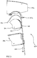
- FIG. 3 shows a schematic structure of a strain relief device 200 according to an embodiment.
- the strain relief device 200 shown here may be the strain relief device 200 FIG. 2 act.
- the strain relief device 200 comprises a strain relief device 302, a pulley 304, a component carrier 202 and an adjustment device 204.
- the component carrier 202 can be fastened to the ceiling element 102.
- the cable 106 is shown to be passed between the sheave 304 and the strain relief 302.
- the strain relief device 200 initially comprises the component carrier 202, wherein in the component carrier 202, the pulley 304 is rotatably mounted.
- the pulley 304 according to this embodiment has an arcuate lateral surface 306 for guiding the wire rope 106, wherein the lateral surface 306 in turn has a groove 308 for receiving the wire rope 106.
- the strain relief 302 is disposed, wherein the wire 106 between the pulley 304 and the strain relief 302 is clamped.
- the strain relief device 302 is attached to the component carrier 202 in the assembled state of the strain relief device 200 and surrounds the lateral surface 306 of the sheave 304.
- the distance of the strain relief device 302 to the lateral surface 306 is invariable on the insertion side of the strain relief device 302. Since the strain relief device 302 is formed according to an embodiment as a sheet metal strip, this is hereinafter referred to as Werentlastungsblechstsammlung 302. At the opposite adjustment side of the Buchentlastungsblechstsammlungs 302 this is connected to the adjusting device 204.
- the adjusting device 204 is for setting a distance between the Ceientlastungsblechstsammlung 302 and the pulley 304. As a result, the holding force is adjustable.
- the adjustment device 204 connects the strain relief strip 302 to the component carrier 202 or to the sheave 304.
- the adjustment device 204 is formed as a screw and is also referred to as an adjustment screw 204.
- the adjusting device 204 may also be formed, for example, as a latching element.
- the component carrier 202 has two side walls which laterally cover the cable pulley 304.
- a passage opening is arranged, through which a rotation axis for rotatably supporting the sheave 304 can be performed.
- the pulley 304 may for this purpose have a corresponding passage opening.
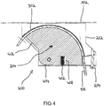
- FIG. 4 shows a schematic cross-sectional view of a strain relief device 200 with a tensioned spring element 402 according to an embodiment.
- the cross-sectional view of the strain relief device 200 comprises the component carrier 202, the cable pulley 304, the Werentlastungsblechstsammlung 302, a spring element 402, the adjusting screw 204.
- the wire 106 is guided over the outer surface of the pulley 304 and abuts the Werentlastungsblechstsammlung 302, ie between pulley 304th and WerentlastungsblechstMail 302 pinched.
- the strain relief device 200 is attached to the ceiling element 102.
- the strain relief device 200 shown here may be the strain relief device 200 FIG. 2 act.
- the spring element 402 is disposed between a bottom part of the component carrier 202 facing away from the ceiling element and the pulley 304.
- the spring element 402 is formed to exert a restoring force on the pulley 304, wherein the restoring force counteracts a force acting on the cable pulley 304 via the wire 106 weight force of the extractor hood.
- the spring element 402 is in FIG. 4 strained due to a fault, for example, because the strain relief device 200 is charged in addition to the weight of the hood. In case of failure, for example, by a slight lifting of the hood during cleaning and then dropping the hood in the wire 106, the load of the wire rope 106 is damped by the spring element.
- the sheave has a first edge surface 404 and a second edge surface 406, wherein the lateral surface of the sheave connects the two edge surfaces 404, 406 and wherein the first edge surface 404 has a recess 408 for receiving the spring element 402.
- the first edge surface 404 faces the bottom part of the component carrier 202 and strikes in the in FIG. 4 shown compressed state of the spring element 402 on the bottom part.
- the distance between the ceiling element and the hood of the extractor device is adjustable by loosening the clamping voltage of the adjusting screw 204.
- the adjusting screw 204 is for adjusting a distance between the Buchentlastungsblechstsammlung 302 and the pulley 304, whereby the holding force is adjustable. The smaller the distance between the Switzerlandentlastungsblechstsammlung 302 and the pulley 304, the greater the frictional force acting and the more strained is the spring element 402.
- FIG. 5 shows a schematic cross-sectional view of the already with reference to FIG. 4 described strain relief device 200 with an unstressed spring element 402 according to one embodiment. Due to the restoring force of the spring element 402, the first edge surface 404 is pushed away from the bottom part of the component carrier 202.
- the wire 106 is guided in the predetermined radius of curvature of, for example, at least 5 cm in a circumferential groove in the spring-mounted pulley 304 and clamped with the Glasentlastungsblechstsammlung 302.
- the wire 106 is clamped by means of surface pressure over the length of WernerchstMails 302 and thus can survive a possible fault.
- the Buchentlastungsblechstsammlungs 302 can be solved for height adjustment and then fixed again.
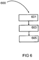
- FIG. 5 shows a flow diagram of an embodiment of a method 600 for mounting a vapor extraction device according to an embodiment.
- a method 600 for mounting a fume extractor comprises the following steps.
- the at least one wire rope is passed through the strain relief device.
- the wire rope is set to the required length.
- the cooker hood is hung on a free end of the wire rope.
Landscapes
- Engineering & Computer Science (AREA)
- General Engineering & Computer Science (AREA)
- Mechanical Engineering (AREA)
- Chemical & Material Sciences (AREA)
- Combustion & Propulsion (AREA)
- Ventilation (AREA)
- Building Environments (AREA)
Abstract
Description
- Der hier vorgestellte Ansatz betrifft eine Vorrichtung für eine Dunstabzugseinrichtung, eine Dunstabzugseinrichtung sowie ein Verfahren zum Montieren einer Dunstabzugseinrichtung, gemäß den Hauptansprüchen.
- Eine Dunstabzugshaube kann über ein Kochfeld gehängt werden, um beim Kochen entstehenden Dunst abzusaugen.
- Von diesem Stand der Technik ausgehend ist es die Aufgabe des hier vorgestellten Ansatzes, eine verbesserte Vorrichtung für eine Dunstabzugseinrichtung, eine verbesserte Dunstabzugseinrichtung sowie ein verbessertes Verfahren zum Montieren einer Dunstabzugseinrichtung zu schaffen.
- Diese Aufgabe wird durch eine Vorrichtung für eine Dunstabzugseinrichtung, eine Dunstabzugseinrichtung sowie ein Verfahren zum Montieren einer Dunstabzugseinrichtung mit den Merkmalen der Hauptansprüche gelöst. Vorteilhafte Ausgestaltungen und Weiterbildungen der Erfindung ergeben sich aus den nachfolgenden Unteransprüchen.
- Die mit dem hier vorgestellten Ansatz einer Vorrichtung für eine Dunstabzugseinrichtung einhergehenden Vorteile bestehen neben einer optional höhenverstellbaren Zugentlastung unter anderem in einer federunterstützenden Dämpfung für den Fehlerfall. Zudem ist eine Flächenklemmung eines die Dunstabzugshaube haltenden Seils möglich. Dabei kann eine Einkerbung und/oder Einschnürung des Seils unterbleiben. Dies ist insbesondere deshalb von Vorteil, da das Seil wenigstens einen elektrischen Leiter enthält, bei welchem Einkerbung und/oder Einschnürung vermieden werden müssen.
- Es wird eine Zugentlastungsvorrichtung für eine Dunstabzugseinrichtung vorgestellt, die eine Dunstabzugshaube, ein Deckenelement und zumindest ein Seil zum Befestigen der Dunstabzugshaube an dem Deckenelement umfasst, wobei die Zugentlastungsvorrichtung die folgenden Merkmale aufweist:
- einen Bauteilträger;
- eine Seilscheibe, die drehbeweglich in dem Bauteilträger gelagert ist und eine Mantelfläche zum Führen des Seils aufweist;
- eine Zugentlastungseinrichtung, die gegenüberliegend zu der Mantelfläche angeordnet ist, wobei das Seil zwischen der Seilscheibe und der Zugentlastungseinrichtung einklemmbar ist; und
- ein Federelement, das mit dem Bauteilträger und der Seilscheibe gekoppelt ist.
- Bei einer Zugentlastungsvorrichtung kann es sich um eine mechanische Schutzvorrichtung für eine Dunstabzugseinrichtung handeln. Bei einer Dunstabzugshaube kann es sich um ein Gerät zum Absaugen und Filtern von beim Kochen entstehenden Wrasen handeln. Bei dem Deckenelement kann es sich um ein Element zur Befestigung einer Dunstabzugshaube an einer Raumdecke handeln. Bei einem Seil kann es sich beispielsweise um ein Drahtseil oder eine Kunststoffseil mit oder ohne integrierte Netzleitung handeln. Bei einem Bauteilträger kann es sich um ein tragendes Bauteil handeln, dass als Gehäuse für die Seilscheibe dienen kann. Bei einer Seilscheibe kann es sich um ein mechanisches Bauteil handeln, dass eine Umlenkung des Seils ermöglicht. Bei einer Zugentlastungseinrichtung kann als Teil des Bauteilträgers oder als ein separates Element ausgeformt sein. Beispielsweise kann es sich bei der Zugentlastungseinrichtung um eine Spannlasche handeln. Das Federelement kann als Druckfeder, beispielsweise als Schraubenfeder oder Blattfeder ausgeformt sein.
- Die Dunstabzugseinrichtung kann somit mit einer speziellen Zugentlastungsvorrichtung mit einer Seilaufhängung mit einer integrierten Netzleitung realisiert werden. Dabei kann die Dunstabzugseinrichtung nachträglich vor Ort in der Höhe verstellbar sein. Vorteilhafterweise kann bei einer geringen Fallhöhe der Dunstabzugshaube, beispielsweise beim Reinigen der Dunstabzugshabe und einem anschließenden Fallenlassen der Dunstabzugshaube in die Seile, weiterhin die nötige elektrotechnische Sicherheit für die integrierte Netzleistung garantieren.
- Gemäß einer Ausführungsform kann die Seilscheibe an der Mantelfläche eine Nut zur Aufnahme des Seils umfassen. Dadurch kann ein Abrutschen des Seils verhindert werden
- Gemäß einer Ausführungsform kann die Zugentlastungseinrichtung als ein Zugentlastungsblechstreifen ausgeformt sein. Dieser ist einfach und kostengünstig herzustellen.
- Gemäß einer Ausführungsform kann der Zugentlastungsblechstreifen an dem Bauteilträger eingehängt sein und die Mantelfläche der Seilscheibe zumindest abschnittsweise umgeben. Durch das Einhängen an dem Bauteilträger kann der Zugentlastungsblechstreifen fixiert werden.
- Gemäß einer Ausführungsform kann die Zugentlastungsvorrichtung eine Einstelleinrichtung zum Einstellen eines Abstands zwischen der Zugentlastungseinrichtung und der Seilscheibe umfassen. Hierdurch ist eine Haltekraft einstellbar, so dass die Zugentlastungsvorrichtung an Dunstabzugshauben unterschiedlichen Gewichts angepasst werden kann
- Gemäß einer Ausführungsform kann die Einstelleinrichtung als eine Einstellschraube ausgeformt sein, die die Zugentlastungseinrichtung mit dem Bauteilträger oder der Seilscheibe verbindet. Mittels der Einstellschraube kann der Abstand zwischen der der Zugentlastungseinrichtung und der Seilscheibe justiert werden.
- Gemäß einer Ausführungsform kann das Federelement ausgeformt sein, um eine Rückstellkraft auf die Seilscheibe auszuüben, wobei die Rückstellkraft einer über das Seil auf die Seilscheibe wirkenden Gewichtskraft der Dunstabzugshaube entgegenwirkt. Dadurch kann das Federelement einen ruckartigen Zug an dem Seil abdämpfen.
- Gemäß einer Ausführungsform kann die Seilscheibe segmentförmig mit einer ersten Randfläche und einer zweiten Randfläche ausgeformt sein, wobei die Mantelfläche die Randflächen verbindet und bogenförmig ausgeformt ist, und wobei die erste Randfläche eine Aussparung zum Aufnehmen des Federelements aufweist. Dabei kann die Seilscheibe eine Drehachse zum drehbeweglichen Lagern der Seilscheibe aufweisen. Dabei kann die Aussparung zwischen der Drehachse und der Mantelfläche angeordnet sein. Dadurch kann eine Hebelwirkung zum Verstärken der Federkraft erreicht werden.
- Es wird eine Dunstabzugseinrichtung mit den folgenden Merkmalen vorgestellt:
- einem Deckenelement, das an einer Raumdecke fixierbar ist;
- einer Dunstabzugshaube zum Absaugen und Filtern der beim Kochen entstehenden Wrasen;
- zumindest einem Seil zum Befestigen der Dunstabzugshaube an dem Deckenelement;
- einer genannten Zugentlastungsvorrichtung, wobei das Seil von der Mantelfläche der Seilscheibe der Zugentlastungsvorrichtung geführt ist.
- Gemäß einer Ausgestaltung enthält das Seil wenigstens einen elektrischen Leiter. Eine bevorzugte Ausführungsform eines solchen Seils sieht vor, dass das Seil aus einer Seele, einem die Seele umschließenden Mantel und einer zwischen Mantel und Seele vorgesehen Zwischenschicht besteht. Dabei sind die Seele und der Mantel jeweils aus einem Draht oder mehreren Drähten gebildet, und bestehen vorzugweise aus einem Metall, während die Zwischenschicht bevorzugt aus einem elastischen Kunststoff besteht. Insbesondere ist vorgesehen, dass die Seele als ein elektrischer Leiter ausgeführt, der Mantel zur Übertragung von Zugkräften ausgebildet und die Zwischenschicht als elektrischer Isolator eingerichtet ist. Es sind auch andere Ausführungsformen des Seils möglich. So kann das Seil keine oder mehrere elektrische Leiter enthalten. Auch ist es möglich, dass die Seele allein oder ergänzend zur Übertragung von Zugkräften eingerichtet ist.
- Gemäß einer Ausführungsform kann das Deckenelement eine Grundplatte aufweisen, die ausgeformt ist, um an der Raumdecke fixiert zu werden. Dabei kann die Zugentlastungsvorrichtung an der Grundplatte befestigt sein. Dadurch kann die Zugentlastungsvorrichtung vollständig in das Deckenelement integriert werden.
- Es wird ein Verfahren zum Montieren einer Dunstabzugseinrichtung vorgestellt, wobei das Verfahren die folgenden Schritte umfasst:
- Herstellen einer mechanischen und einer elektrischen Verbindung des zumindest einen Seils mit der Dunstabzugshaube;
- Führen des zumindest einen Seils durch die Zugentlastungsvorrichtung;
- Herstellen einer mechanischen und einer elektrischen Verbindung des zumindest einen Seils mit dem Deckenelement; und
- Einstellen des Seils auf die erforderliche Länge.
- Auch wenn der beschriebene Ansatz anhand eines Haushaltgerät beschrieben wird, kann die hier beschriebene Vorrichtung für eine Dunstabzugseinrichtung sowie das Verfahren zum Montieren einer Dunstabzugseinrichtung entsprechend im Zusammenhang mit einem gewerblichen oder professionellen Gerät, beispielsweise einer Dunstabzugseinrichtung für Großküchen und/oder Restaurants verwendet werden.
- Ein Ausführungsbeispiel der Erfindung ist in den Zeichnungen rein schematisch dargestellt und wird nachfolgend näher beschrieben. Es zeigt
- Figur 1
- eine schematische Darstellung einer Dunstabzugseinrichtung gemäß einem Ausführungsbeispiel;
- Figur 2
- eine schematische Darstellung einer Zugentlastungsvorrichtung gemäß einem Ausführungsbeispiel;
- Figur 3
- einen schematischen Aufbau einer Zugentlastungsvorrichtung gemäß einem Ausführungsbeispiel;
- Figur 4
- eine schematische Querschnittsansicht einer Zugentlastungsvorrichtung mit einem gespannten Federelement gemäß einem Ausführungsbeispiel;
- Figur 5
- eine schematische Querschnittsansicht einer Zugentlastungsvorrichtung mit einem ungespannten Federelement gemäß einem Ausführungsbeispiel; und
- Figur 6
- ein Ablaufdiagram eines Ausführungsbeispiels eines Verfahrens zum Montieren einer Dunstabzugseinrichtung gemäß einem Ausführungsbeispiel.
-
Figur 1 zeigt eine schematische Darstellung einer Dunstabzugseinrichtung 100 gemäß einem Ausführungsbeispiel. Die Dunstabzugseinrichtung 100 umfasst ein Deckenelement 102 und eine Dunstabzugshaube 104. Die Dunstabzugshaube 104 ist mittels zumindest eines Seils 106, im Folgenden als Drahtseils 106 bezeichnet, an dem Deckenelement 102 befestigt. Das Deckenelement 102 ist mechanisch an einer Raumdecke fixierbar und dient der elektrischen Anbindung der Dunstabzugshaube 104 an eine Netzspannung. Die Dunstabzugshaube 104 ist mit einem einstellbaren Abstand zum Deckenelement 102 in hängender Weise befestigbar. - Gemäß diesem Ausführungsbeispiel weist die Dunstabzugseinrichtung 100 zusätzlich zum Drahtseil 106 optional drei weitere Drahtseile 108 auf, die je als Verbindungsdrahtseil zum Aufhängen der Dunstabzugshaube 104 an dem Deckenelement 102 fungieren. Die Dunstabzugshaube 104 umfasst beispielsweise eine gesamte Lüftungstechnik, einschließlich Fettfilter, Geruchsfilter, Lüfter, Motor, Steuerung und Bedienelemente und dient dem Absaugen und Filtern der beim Kochen entstehenden Wrasen. Alternativ ist die Dunstabzugseinrichtung 100 mit mehr als vier Drahtseilen 106 realisiert.
- Für jedes Drahtseil 106 ist gemäß einem Ausführungsbeispiel eine Zugentlastungsvorrichtung vorgesehen, wie sie beispielsweise in
Figur 2 gezeigt ist. -
Figur 2 zeigt eine schematische Darstellung einer Zugentlastungsvorrichtung 200 gemäß einem Ausführungsbeispiel. Die Darstellung der Zugentlastungsvorrichtung 200 umfasst einen Bauteilträger 202, eine Einstelleinrichtung 204, ein Deckenelement 102 sowie ein Drahtseil 106. Das Deckenelement 102 weist hierbei eine Grundplatte auf, die ausgeformt ist, um an der Raumdecke fixiert zu werden. Die Zugentlastungsvorrichtung 200 ist an der Grundplatte befestigt. - Für die Montage der Dunstabzugseinrichtung 100 sind vorzugsweise das Deckenelement 102 und eine Dunstabzugshaube 104 bereits ab Werk über das Drahtseil 106 miteinander verbunden. Eine derart gelieferte Dunstabzugseinrichtung 100 wird vor Ort als Gesamtes an der Raumdecke aufgehängt.
- Alternativ oder auch im Kundendienstfall, beispielsweise bei Austausch vom Drahtseil 106, kann bei der Montage der Dunstabzugseinrichtung zunächst das Deckenelement 102 an der Raumdecke fixiert und im Anschluss dann das Drahtseil 106 durch die Zugentlastungsvorrichtung 200 geführt und zumindest mechanisch, gegebenenfalls aber auch elektrisch, mit diversen Einrichtungen des Deckenelements 102 verbunden werden. Dabei wird das Drahtseil 106 bereits auf die erforderliche Länge zwischen dem Deckenelement 102 und der Dunstabzugshaube eingestellt und eine Zugentlastungseinrichtung der Zugentlastungsvorrichtung 200 mittels einer Einstelleinrichtung 204 gespannt, wobei das Drahtseil 106 zwischen einer Seilscheibe der Zugentlastungvorrichtung und der Zugentlastungseinrichtung kraftschlüssig gehalten wird. Anschließend wird die Dunstabzugshaube an dem freien Ende des Drahtseils 106 eingehängt.
- In beiden Fällen kann eine Justierung der Länge des Drahtseils 106 durch ein leichtes Lösen der Klemmspannung an der Einstelleinrichtung 204 erfolgen.
-
Figur 3 zeigt einen schematischen Aufbau einer Zugentlastungsvorrichtung 200 gemäß einem Ausführungsbeispiel. Bei der hier dargestellten Zugentlastungsvorrichtung 200 kann es sich um die Zugentlastungsvorrichtung 200 ausFigur 2 handeln. Die Zugentlastungsvorrichtung 200 umfasst eine Zugentlastungseinrichtung 302, eine Seilscheibe 304, einen Bauteilträger 202 sowie eine Einstelleinrichtung 204. Der Bauteilträger 202 kann an dem Deckenelement 102 befestigt werden. InFigur 3 ist ferner das Drahtseil 106 gezeigt, dass zwischen der Seilscheibe 304 und der Zugentlastungseinrichtung 302 durchgeführt wird. - Die Zugentlastungsvorrichtung 200 umfasst zunächst den Bauteilträger 202, wobei in dem Bauteilträger 202 die Seilscheibe 304 drehbeweglich gelagert ist. Die Seilscheibe 304 weist gemäß diesem Ausführungsbeispiel eine bogenförmige Mantelfläche 306 zum Führen des Drahtseils 106 auf, wobei die Mantelfläche 306 wiederrum eine Nut 308 zur Aufnahme des Drahtseils 106 aufweist. Gegenüberliegend zur Mantelfläche 306 der Seilscheibe 304 ist die Zugentlastungseinrichtung 302 angeordnet, wobei das Drahtseil 106 zwischen der Seilscheibe 304 und der Zugentlastungseinrichtung 302 einklemmbar ist. Ferner ist die Zugentlastungseinrichtung 302 im montierten Zustand der Zugentlastungsvorrichtung 200 an dem Bauteilträger 202 angehängt und umgibt die Mantelfläche 306 der Seilscheibe 304. Der Abstand der Zugentlastungseinrichtung 302 zur Mantelfläche 306 ist an der Einhängeseite der Zugentlastungseinrichtung 302 unveränderlich. Da die Zugentlastungseinrichtung 302 gemäß einem Ausführungsbeispiel als ein Blechstreifen ausgeformt ist, wird diese im Weiteren auch als Zugentlastungsblechstreifen 302 bezeichnet. An der gegenüberliegenden Einstellseite des Zugentlastungsblechstreifens 302 ist dieser mit der Einstelleinrichtung 204 verbunden. Die Einstelleinrichtung 204 dient dem Einstellen eines Abstands zwischen dem Zugentlastungsblechstreifen 302 und der Seilscheibe 304. Hierdurch ist die Haltekraft einstellbar. Ferner verbindet die Einstelleinrichtung 204 den Zugentlastungsblechstreifen 302 mit dem Bauteilträger 202 oder mit der Seilscheibe 304. Gemäß einem Ausführungsbeispiel ist die Einstelleinrichtung 204 als eine Schraube ausgeformt und wird im Weiteren auch als Einstellschraube 204 bezeichnet. Optional kann die Einstelleinrichtung 204 aber ebenso beispielsweise als ein Rastelement ausgeformt sein.
- Gemäß einem Ausführungsbeispiel weist der Bauteilträger 202 zwei Seitenwände auf, die die Seilscheibe 304 seitlich abdecken. In den Seitenwänden ist je eine Durchgangsöffnung angeordnet, durch die eine Drehachse zum drehbeweglichen Lagern der Seilscheibe 304 geführt werden kann. Die Seilscheibe 304 kann dazu eine entsprechende Durchgangsöffnung aufweisen.
-
Figur 4 zeigt eine schematische Querschnittsansicht einer Zugentlastungsvorrichtung 200 mit einem gespannten Federelement 402 gemäß einem Ausführungsbeispiel. Die Querschnittsansicht der Zugentlastungsvorrichtung 200 umfasst den Bauteilträger 202, die Seilscheibe 304, den Zugentlastungsblechstreifen 302, ein Federelement 402, die Einstellschraube 204. Das Drahtseil 106 ist über die Mantelfläche der Seilscheibe 304 geführt und liegt an der Zugentlastungsblechstreifen 302 an, ist also zwischen Seilscheibe 304 und Zugentlastungsblechstreifen 302 eingeklemmt. Die Zugentlastungsvorrichtung 200 ist an dem Deckenelement 102 befestigt. Bei der hier dargestellten Zugentlastungsvorrichtung 200 kann es sich um die Zugentlastungsvorrichtung 200 ausFigur 2 handeln. - Das Federelement 402 ist zwischen einem dem Deckenelement abgewandten Bodenteil des Bauteilträgers 202 und der Seilscheibe 304 angeordnet. Das Federelement 402 ist ausgeformt, um eine Rückstellkraft auf die Seilscheibe 304 auszuüben, wobei die Rückstellkraft einer über das Drahtseil 106 auf die Seilscheibe 304 wirkenden Gewichtskraft der Dunstabzugshaube entgegenwirkt. Gemäß einem Ausführungsbeispiel ist das Federelement 402 in
Figur 4 aufgrund eines Fehlerfalls gespannt bzw. belastet, beispielsweise weil die Zugentlastungsvorrichtung 200 zusätzlich zu dem Gewicht der Dunstabzugshaube belastet ist. Im Fehlerfall, beispielsweise durch ein leichtes Anheben der Dunstabzugshaube bei der Reinigung und einem anschließenden Fallenlassen der Dunstabzugshaube in das Drahtseil 106, wird die Belastung des Drahtseils 106 durch das Federelement gedämpft. - Die Seilscheibe weist eine erste Randfläche 404 und eine zweite Randfläche 406 auf, wobei die Mantelfläche der Seilscheibe die beiden Randflächen 404, 406 verbindet und wobei die erste Randfläche 404 eine Aussparung 408 zum Aufnehmen des Federelements 402 aufweist. Die erste Randfläche 404 ist dem Bodenteil des Bauteilträgers 202 zugewandt und schlägt in dem in
Figur 4 gezeigten gestauchten Zustand des Federelements 402 an dem Bodenteil an. Der Abstand zwischen dem Deckenelement und der Dunstabzugshaube der Dunstabzugseinrichtung ist über ein Lösen der Klemmspannung an der Einstellschraube 204 verstellbar. Ferner dient die Einstellschraube 204 dem Einstellen eines Abstands zwischen dem Zugentlastungsblechstreifen 302 und der Seilscheibe 304, wodurch die Haltekraft einstellbar ist. Je geringer der Abstand zwischen dem Zugentlastungsblechstreifen 302 und der Seilscheibe 304 ist, desto größer ist die wirkende Reibkraft und desto gespannter ist das Federelement 402. -
Figur 5 zeigt eine schematische Querschnittsansicht der bereits anhand vonFigur 4 beschriebenen Zugentlastungsvorrichtung 200 mit einem ungespannten Federelement 402 gemäß einem Ausführungsbeispiel. Durch die Rückstellkraft des Federelements 402 ist die erste Randfläche 404 von dem Bodenteil des Bauteilträgers 202 weggedrückt. - Gemäß dem gezeigten Ausführungsbeispiel ist das Drahtseil 106 im vorgegebenem Krümmungsradius von beispielhaft mindestens 5cm in einer umlaufenden Nut in der federnd gelagerten Seilscheibe 304 geführt und mit dem Zugentlastungsblechstreifen 302 geklemmt. In dieser umlaufenden Nut wird das Drahtseil 106 mittels Flächenpressung über die Länge des Zugentlastungsblechstreifens 302 geklemmt und kann somit einen möglichen Fehlerfall überstehen. Der Zugentlastungsblechstreifens 302 kann zur Höhenverstellung gelöst und anschließend wieder befestigt werden.
-
Figur 6 zeigt ein Ablaufdiagram eines Ausführungsbeispiels eines Verfahrens 600 zum Montieren einer Dunstabzugseinrichtung gemäß einem Ausführungsbeispiel. - Ein Verfahren 600 zum Montieren einer Dunstabzugseinrichtung weist die folgenden Schritte auf. In einem Schritt 601 wird das zumindest eine Drahtseil durch die Zugentlastungsvorrichtung geführt. Ferner wird in einem Schritt 603 das Drahtseil auf die erforderliche Länge eingestellt. Schließlich wird in einem Schritt 605 die Dunstabzugshaube an einem freien Ende des Drahtseils eingehängt.
Claims (13)
- Zugentlastungsvorrichtung (200) für eine Dunstabzugseinrichtung (100), die eine Dunstabzugshaube (104), ein Deckenelement (102) und zumindest ein Seil (106) zum Befestigen der Dunstabzugshaube (104) an dem Deckenelement (102) umfasst, wobei die Zugentlastungsvorrichtung (200) die folgenden Merkmale aufweist:einen Bauteilträger (202);eine Seilscheibe (304), die drehbeweglich in dem Bauteilträger (202) gelagert ist und eine Mantelfläche (306) zum Führen des Seils (106) aufweist;eine Zugentlastungseinrichtung (302), die gegenüberliegend zu der Mantelfläche (306) angeordnet ist, wobei das Seil (106) zwischen der Seilscheibe (304) und der Zugentlastungseinrichtung (302) einklemmbar ist; undein Federelement (402), das mit dem Bauteilträger (202) und der Seilscheibe (304) gekoppelt ist.
- Zugentlastungsvorrichtung (200) gemäß Anspruch 1, wobei die Seilscheibe (304) an der Mantelfläche (306) eine Nut (308) zur Aufnahme des Seils (106) umfasst.
- Zugentlastungsvorrichtung (200) gemäß einem der vorangegangenen Ansprüche, bei der die Zugentlastungseinrichtung (302) als ein Zugentlastungsblechstreifen (302) ausgeformt ist.
- Zugentlastungsvorrichtung (200) gemäß Anspruch 3, bei der der Zugentlastungsblechstreifen (302) an dem Bauteilträger (202) eingehängt ist und die Mantelfläche (306) der Seilscheibe (304) zumindest abschnittsweise umgibt.
- Zugentlastungsvorrichtung (200) gemäß einem der vorangegangenen Ansprüche, mit einer Einstelleinrichtung (204) zum Einstellen eines Abstands zwischen der Zugentlastungseinrichtung (302) und der Seilscheibe (304).
- Zugentlastungsvorrichtung (200) gemäß Anspruch 5, bei der die Einstelleinrichtung (204) als eine Einstellschraube (204) ausgeformt ist, die die Zugentlastungseinrichtung (302) mit dem Bauteilträger (202) oder der Seilscheibe (304) verbindet.
- Zugentlastungsvorrichtung (200) gemäß einem der vorangegangenen Ansprüche, bei der das Federelement (402) ausgeformt ist, um eine Rückstellkraft auf die Seilscheibe (304) auszuüben, wobei die Rückstellkraft einer über das Seil (106) auf die Seilscheibe (304) wirkenden Gewichtskraft der Dunstabzugshaube (104) entgegenwirkt.
- Zugentlastungsvorrichtung (200) gemäß einem der vorangegangenen Ansprüche, bei der die Seilscheibe (304) segmentförmig mit einer ersten Randfläche (404) und einer zweite Randfläche (406) ausgeformt ist, wobei die Mantelfläche (306) die Randflächen (404, 406) verbindet und bogenförmig ausgeformt ist, und wobei die erste Randfläche (404) eine Aussparung (408) zum Aufnehmen des Federelements (402) aufweist.
- Zugentlastungsvorrichtung (200) gemäß Anspruch 8, bei der die Seilscheibe (304) eine Drehachse zum drehbeweglichen Lagern der Seilscheibe (304) aufweist, wobei die Aussparung (408) zwischen der Drehachse und der Mantelfläche (306) angeordnet ist.
- Dunstabzugseinrichtung (100) mit folgenden Merkmalen:einem Deckenelement (102), das an einer Raumdecke fixierbar ist;einer Dunstabzugshaube (104) zum Absaugen und Filtern der beim Kochen entstehenden Wrasen;zumindest einem Seil (106) zum Befestigen der Dunstabzugshaube (104) an dem Deckenelement (102);einer Zugentlastungsvorrichtung (200) gemäß einem der vorangegangenen Ansprüche, wobei das Seil (106) von der Mantelfläche (306) der Seilscheibe (304) der Zugentlastungsvorrichtung (200) geführt ist.
- Dunstabzugseinrichtung (100) gemäß Anspruch 10, wobei das Deckenelement (102) eine Grundplatte aufweist, die ausgeformt ist, um an der Raumdecke fixiert zu werden, und wobei die Zugentlastungsvorrichtung (200) an der Grundplatte befestigt ist.
- Dunstabzugseinrichtung (100) gemäß Anspruch 10 oder 11, wobei das das Seil (106) wenigstens einen elektrischen Leiter enthält.
- Verfahren (600) zum Montieren einer Dunstabzugseinrichtung (100) gemäß den Ansprüchen 10, 11 oder 12, wobei das Verfahren (600) die folgenden Schritte umfasst:Herstellen einer mechanischen und einer elektrischen Verbindung des zumindest einen Seils (106) mit der Dunstabzugshaube (104);Führen (601) des zumindest einen Seils (106) durch die Zugentlastungsvorrichtung (200);Herstellen einer mechanischen und einer elektrischen Verbindung des zumindest einen Seils (106) mit dem Deckenelement (102); undEinstellen (603) des Seils (106) auf die erforderliche Länge.
Priority Applications (1)
| Application Number | Priority Date | Filing Date | Title |
|---|---|---|---|
| PL18192752T PL3467386T3 (pl) | 2017-09-29 | 2018-09-05 | Urządzenie okapu wyciągowego i sposób montażu urządzenia okapu wyciągowego |
Applications Claiming Priority (1)
| Application Number | Priority Date | Filing Date | Title |
|---|---|---|---|
| DE102017122667.2A DE102017122667B3 (de) | 2017-09-29 | 2017-09-29 | Zugentlastungsvorrichtung für eine Dunstabzugseinrichtung, Dunstabzugseinrichtung und Verfahren zum Montieren einer Dunstabzugseinrichtung |
Publications (2)
| Publication Number | Publication Date |
|---|---|
| EP3467386A1 true EP3467386A1 (de) | 2019-04-10 |
| EP3467386B1 EP3467386B1 (de) | 2019-11-13 |
Family
ID=63517777
Family Applications (1)
| Application Number | Title | Priority Date | Filing Date |
|---|---|---|---|
| EP18192752.6A Active EP3467386B1 (de) | 2017-09-29 | 2018-09-05 | Dunstabzugseinrichtung und verfahren zum montieren einer dunstabzugseinrichtung |
Country Status (4)
| Country | Link |
|---|---|
| EP (1) | EP3467386B1 (de) |
| DE (1) | DE102017122667B3 (de) |
| ES (1) | ES2766248T3 (de) |
| PL (1) | PL3467386T3 (de) |
Cited By (1)
| Publication number | Priority date | Publication date | Assignee | Title |
|---|---|---|---|---|
| EP4015917A1 (de) * | 2020-12-16 | 2022-06-22 | Novy International NV | Aufhängesystem für eine dunstabzugshaube |
Citations (3)
| Publication number | Priority date | Publication date | Assignee | Title |
|---|---|---|---|---|
| DE4409191C1 (de) * | 1994-03-17 | 1995-07-20 | Gutehoffnungshuette Man | Seilklemmvorrichtung für ein zugbelastetes Seil |
| JP2005055126A (ja) * | 2003-08-07 | 2005-03-03 | Kanden Fudosan Kk | レンジフード |
| EP2327936A1 (de) * | 2009-11-26 | 2011-06-01 | Faber S.p.A. | Absenkbare Dunstabzugshaube |
Family Cites Families (3)
| Publication number | Priority date | Publication date | Assignee | Title |
|---|---|---|---|---|
| DE4105004A1 (de) | 1991-02-19 | 1992-08-20 | Kueppersbusch | Dunstabzug |
| EP2317232A1 (de) | 2009-11-03 | 2011-05-04 | Miele & Cie. KG | Wrasenabzugsvorrichtung, insbesondere Dunstabzugshaube für den Umluftbetrieb |
| DE102016103125A1 (de) | 2016-02-23 | 2017-08-24 | Miele & Cie. Kg | Tragseil für eine Dunstabzugshaube und Dunstabzugshaube |
-
2017
- 2017-09-29 DE DE102017122667.2A patent/DE102017122667B3/de active Active
-
2018
- 2018-09-05 PL PL18192752T patent/PL3467386T3/pl unknown
- 2018-09-05 EP EP18192752.6A patent/EP3467386B1/de active Active
- 2018-09-05 ES ES18192752T patent/ES2766248T3/es active Active
Patent Citations (3)
| Publication number | Priority date | Publication date | Assignee | Title |
|---|---|---|---|---|
| DE4409191C1 (de) * | 1994-03-17 | 1995-07-20 | Gutehoffnungshuette Man | Seilklemmvorrichtung für ein zugbelastetes Seil |
| JP2005055126A (ja) * | 2003-08-07 | 2005-03-03 | Kanden Fudosan Kk | レンジフード |
| EP2327936A1 (de) * | 2009-11-26 | 2011-06-01 | Faber S.p.A. | Absenkbare Dunstabzugshaube |
Cited By (2)
| Publication number | Priority date | Publication date | Assignee | Title |
|---|---|---|---|---|
| EP4015917A1 (de) * | 2020-12-16 | 2022-06-22 | Novy International NV | Aufhängesystem für eine dunstabzugshaube |
| BE1028898B1 (nl) * | 2020-12-16 | 2022-07-19 | Novy Int Nv | Ophangsysteem voor een dampkap |
Also Published As
| Publication number | Publication date |
|---|---|
| ES2766248T3 (es) | 2020-06-12 |
| EP3467386B1 (de) | 2019-11-13 |
| PL3467386T3 (pl) | 2020-04-30 |
| DE102017122667B3 (de) | 2018-12-06 |
Similar Documents
| Publication | Publication Date | Title |
|---|---|---|
| EP3211326B1 (de) | Dunstabzugshaube | |
| EP3467386B1 (de) | Dunstabzugseinrichtung und verfahren zum montieren einer dunstabzugseinrichtung | |
| DE102014110533B4 (de) | Anschlusssystem für elektrische Geräte | |
| EP3480895B1 (de) | Geräteanschlusseinheit für ein elektrogerät und elektrogerät | |
| DE102010029768A1 (de) | Teleskopauszugsvorrichtung und Haushaltsgerät | |
| DE102015119389A1 (de) | Steckdosenpolkontakt | |
| DE102005001314A1 (de) | Vorrichtung zum Öffnen und/oder Schließen einer Tür | |
| EP2526342B1 (de) | System aus mehreren in einen ausschnitt einer arbeitsplatte einsetzbaren gargeräten und verfahren zum montieren eines solchen systems | |
| DE602004012953T2 (de) | Vibrationsisolierendes bausystem | |
| DE29601735U1 (de) | Widerstandsanordnung zu einem zum Schalten von kapazitiven Lasten bestimmten elektromagnetischen Schaltgerät | |
| DE102012007298A1 (de) | Vorrichtung zum höhenverstellbaren Abhängen eines elektrischen Gerätes | |
| DE202012102254U1 (de) | Linearantrieb | |
| DE102013215171B4 (de) | Federelement zur Leuchtenmontage | |
| DE102014220307B3 (de) | Befestigungsvorrichtung zum Festlegen einer Trägeranordnung einer Türkommunikationseinrichtung in einem Einbaugehäuse | |
| EP3685472B1 (de) | Schaltschrank mit stromrichter mit kabelanschlusselementen | |
| EP2955729A1 (de) | Stützvorrichtung eines Aktivteils eines Stromwandlers | |
| DE102019100046A1 (de) | Kochfeldsystem | |
| DE19906686A1 (de) | Anschlußsockel für Lampenbaldachin bei entfernt liegendem Elektroanschluß | |
| DE102005059179A1 (de) | Gleichstrommotor mit Entstöreinrichtung | |
| DE102017114411A1 (de) | Aktuatorvorrichtung | |
| DE202019105532U1 (de) | Elektrische Leuchte | |
| DE102016217501A1 (de) | Hängeanordnung für elektrische Betriebsmittel | |
| DE202009010670U1 (de) | Vorrichtung zum Ausrichten von eine Trägerplatte aufweisenden Elektroarmaturen in Unterputzdosen | |
| DE102012100643A1 (de) | Befestigungsvorrichtung für ein Wand- oder Deckenverkleidungselement | |
| DE102015100204A1 (de) | Kochfeldeinrichtung und Verfahren zur Installation |
Legal Events
| Date | Code | Title | Description |
|---|---|---|---|
| PUAI | Public reference made under article 153(3) epc to a published international application that has entered the european phase |
Free format text: ORIGINAL CODE: 0009012 |
|
| STAA | Information on the status of an ep patent application or granted ep patent |
Free format text: STATUS: THE APPLICATION HAS BEEN PUBLISHED |
|
| STAA | Information on the status of an ep patent application or granted ep patent |
Free format text: STATUS: REQUEST FOR EXAMINATION WAS MADE |
|
| AK | Designated contracting states |
Kind code of ref document: A1 Designated state(s): AL AT BE BG CH CY CZ DE DK EE ES FI FR GB GR HR HU IE IS IT LI LT LU LV MC MK MT NL NO PL PT RO RS SE SI SK SM TR |
|
| AX | Request for extension of the european patent |
Extension state: BA ME |
|
| 17P | Request for examination filed |
Effective date: 20190307 |
|
| RBV | Designated contracting states (corrected) |
Designated state(s): AL AT BE BG CH CY CZ DE DK EE ES FI FR GB GR HR HU IE IS IT LI LT LU LV MC MK MT NL NO PL PT RO RS SE SI SK SM TR |
|
| GRAP | Despatch of communication of intention to grant a patent |
Free format text: ORIGINAL CODE: EPIDOSNIGR1 |
|
| STAA | Information on the status of an ep patent application or granted ep patent |
Free format text: STATUS: GRANT OF PATENT IS INTENDED |
|
| INTG | Intention to grant announced |
Effective date: 20190705 |
|
| GRAS | Grant fee paid |
Free format text: ORIGINAL CODE: EPIDOSNIGR3 |
|
| GRAA | (expected) grant |
Free format text: ORIGINAL CODE: 0009210 |
|
| STAA | Information on the status of an ep patent application or granted ep patent |
Free format text: STATUS: THE PATENT HAS BEEN GRANTED |
|
| AK | Designated contracting states |
Kind code of ref document: B1 Designated state(s): AL AT BE BG CH CY CZ DE DK EE ES FI FR GB GR HR HU IE IS IT LI LT LU LV MC MK MT NL NO PL PT RO RS SE SI SK SM TR |
|
| REG | Reference to a national code |
Ref country code: CH Ref legal event code: EP Ref country code: AT Ref legal event code: REF Ref document number: 1202056 Country of ref document: AT Kind code of ref document: T Effective date: 20191115 |
|
| REG | Reference to a national code |
Ref country code: DE Ref legal event code: R096 Ref document number: 502018000366 Country of ref document: DE |
|
| REG | Reference to a national code |
Ref country code: IE Ref legal event code: FG4D Free format text: LANGUAGE OF EP DOCUMENT: GERMAN |
|
| REG | Reference to a national code |
Ref country code: NL Ref legal event code: FP |
|
| REG | Reference to a national code |
Ref country code: LT Ref legal event code: MG4D |
|
| PG25 | Lapsed in a contracting state [announced via postgrant information from national office to epo] |
Ref country code: PT Free format text: LAPSE BECAUSE OF FAILURE TO SUBMIT A TRANSLATION OF THE DESCRIPTION OR TO PAY THE FEE WITHIN THE PRESCRIBED TIME-LIMIT Effective date: 20200313 Ref country code: LT Free format text: LAPSE BECAUSE OF FAILURE TO SUBMIT A TRANSLATION OF THE DESCRIPTION OR TO PAY THE FEE WITHIN THE PRESCRIBED TIME-LIMIT Effective date: 20191113 Ref country code: GR Free format text: LAPSE BECAUSE OF FAILURE TO SUBMIT A TRANSLATION OF THE DESCRIPTION OR TO PAY THE FEE WITHIN THE PRESCRIBED TIME-LIMIT Effective date: 20200214 Ref country code: NO Free format text: LAPSE BECAUSE OF FAILURE TO SUBMIT A TRANSLATION OF THE DESCRIPTION OR TO PAY THE FEE WITHIN THE PRESCRIBED TIME-LIMIT Effective date: 20200213 Ref country code: SE Free format text: LAPSE BECAUSE OF FAILURE TO SUBMIT A TRANSLATION OF THE DESCRIPTION OR TO PAY THE FEE WITHIN THE PRESCRIBED TIME-LIMIT Effective date: 20191113 Ref country code: LV Free format text: LAPSE BECAUSE OF FAILURE TO SUBMIT A TRANSLATION OF THE DESCRIPTION OR TO PAY THE FEE WITHIN THE PRESCRIBED TIME-LIMIT Effective date: 20191113 Ref country code: BG Free format text: LAPSE BECAUSE OF FAILURE TO SUBMIT A TRANSLATION OF THE DESCRIPTION OR TO PAY THE FEE WITHIN THE PRESCRIBED TIME-LIMIT Effective date: 20200213 Ref country code: FI Free format text: LAPSE BECAUSE OF FAILURE TO SUBMIT A TRANSLATION OF THE DESCRIPTION OR TO PAY THE FEE WITHIN THE PRESCRIBED TIME-LIMIT Effective date: 20191113 |
|
| PG25 | Lapsed in a contracting state [announced via postgrant information from national office to epo] |
Ref country code: IS Free format text: LAPSE BECAUSE OF FAILURE TO SUBMIT A TRANSLATION OF THE DESCRIPTION OR TO PAY THE FEE WITHIN THE PRESCRIBED TIME-LIMIT Effective date: 20200313 Ref country code: RS Free format text: LAPSE BECAUSE OF FAILURE TO SUBMIT A TRANSLATION OF THE DESCRIPTION OR TO PAY THE FEE WITHIN THE PRESCRIBED TIME-LIMIT Effective date: 20191113 Ref country code: HR Free format text: LAPSE BECAUSE OF FAILURE TO SUBMIT A TRANSLATION OF THE DESCRIPTION OR TO PAY THE FEE WITHIN THE PRESCRIBED TIME-LIMIT Effective date: 20191113 |
|
| REG | Reference to a national code |
Ref country code: ES Ref legal event code: FG2A Ref document number: 2766248 Country of ref document: ES Kind code of ref document: T3 Effective date: 20200612 |
|
| PG25 | Lapsed in a contracting state [announced via postgrant information from national office to epo] |
Ref country code: AL Free format text: LAPSE BECAUSE OF FAILURE TO SUBMIT A TRANSLATION OF THE DESCRIPTION OR TO PAY THE FEE WITHIN THE PRESCRIBED TIME-LIMIT Effective date: 20191113 |
|
| PG25 | Lapsed in a contracting state [announced via postgrant information from national office to epo] |
Ref country code: EE Free format text: LAPSE BECAUSE OF FAILURE TO SUBMIT A TRANSLATION OF THE DESCRIPTION OR TO PAY THE FEE WITHIN THE PRESCRIBED TIME-LIMIT Effective date: 20191113 Ref country code: DK Free format text: LAPSE BECAUSE OF FAILURE TO SUBMIT A TRANSLATION OF THE DESCRIPTION OR TO PAY THE FEE WITHIN THE PRESCRIBED TIME-LIMIT Effective date: 20191113 Ref country code: RO Free format text: LAPSE BECAUSE OF FAILURE TO SUBMIT A TRANSLATION OF THE DESCRIPTION OR TO PAY THE FEE WITHIN THE PRESCRIBED TIME-LIMIT Effective date: 20191113 Ref country code: CZ Free format text: LAPSE BECAUSE OF FAILURE TO SUBMIT A TRANSLATION OF THE DESCRIPTION OR TO PAY THE FEE WITHIN THE PRESCRIBED TIME-LIMIT Effective date: 20191113 |
|
| REG | Reference to a national code |
Ref country code: DE Ref legal event code: R097 Ref document number: 502018000366 Country of ref document: DE |
|
| PG25 | Lapsed in a contracting state [announced via postgrant information from national office to epo] |
Ref country code: SM Free format text: LAPSE BECAUSE OF FAILURE TO SUBMIT A TRANSLATION OF THE DESCRIPTION OR TO PAY THE FEE WITHIN THE PRESCRIBED TIME-LIMIT Effective date: 20191113 Ref country code: SK Free format text: LAPSE BECAUSE OF FAILURE TO SUBMIT A TRANSLATION OF THE DESCRIPTION OR TO PAY THE FEE WITHIN THE PRESCRIBED TIME-LIMIT Effective date: 20191113 |
|
| PLBE | No opposition filed within time limit |
Free format text: ORIGINAL CODE: 0009261 |
|
| STAA | Information on the status of an ep patent application or granted ep patent |
Free format text: STATUS: NO OPPOSITION FILED WITHIN TIME LIMIT |
|
| 26N | No opposition filed |
Effective date: 20200814 |
|
| PG25 | Lapsed in a contracting state [announced via postgrant information from national office to epo] |
Ref country code: SI Free format text: LAPSE BECAUSE OF FAILURE TO SUBMIT A TRANSLATION OF THE DESCRIPTION OR TO PAY THE FEE WITHIN THE PRESCRIBED TIME-LIMIT Effective date: 20191113 |
|
| REG | Reference to a national code |
Ref country code: BE Ref legal event code: MM Effective date: 20200930 |
|
| PG25 | Lapsed in a contracting state [announced via postgrant information from national office to epo] |
Ref country code: LU Free format text: LAPSE BECAUSE OF NON-PAYMENT OF DUE FEES Effective date: 20200905 |
|
| PG25 | Lapsed in a contracting state [announced via postgrant information from national office to epo] |
Ref country code: BE Free format text: LAPSE BECAUSE OF NON-PAYMENT OF DUE FEES Effective date: 20200930 Ref country code: IE Free format text: LAPSE BECAUSE OF NON-PAYMENT OF DUE FEES Effective date: 20200905 |
|
| REG | Reference to a national code |
Ref country code: CH Ref legal event code: PL |
|
| PG25 | Lapsed in a contracting state [announced via postgrant information from national office to epo] |
Ref country code: MT Free format text: LAPSE BECAUSE OF FAILURE TO SUBMIT A TRANSLATION OF THE DESCRIPTION OR TO PAY THE FEE WITHIN THE PRESCRIBED TIME-LIMIT Effective date: 20191113 Ref country code: CY Free format text: LAPSE BECAUSE OF FAILURE TO SUBMIT A TRANSLATION OF THE DESCRIPTION OR TO PAY THE FEE WITHIN THE PRESCRIBED TIME-LIMIT Effective date: 20191113 |
|
| PG25 | Lapsed in a contracting state [announced via postgrant information from national office to epo] |
Ref country code: MK Free format text: LAPSE BECAUSE OF FAILURE TO SUBMIT A TRANSLATION OF THE DESCRIPTION OR TO PAY THE FEE WITHIN THE PRESCRIBED TIME-LIMIT Effective date: 20191113 Ref country code: MC Free format text: LAPSE BECAUSE OF FAILURE TO SUBMIT A TRANSLATION OF THE DESCRIPTION OR TO PAY THE FEE WITHIN THE PRESCRIBED TIME-LIMIT Effective date: 20191113 |
|
| PG25 | Lapsed in a contracting state [announced via postgrant information from national office to epo] |
Ref country code: LI Free format text: LAPSE BECAUSE OF NON-PAYMENT OF DUE FEES Effective date: 20210930 Ref country code: CH Free format text: LAPSE BECAUSE OF NON-PAYMENT OF DUE FEES Effective date: 20210930 |
|
| P01 | Opt-out of the competence of the unified patent court (upc) registered |
Effective date: 20230528 |
|
| REG | Reference to a national code |
Ref country code: AT Ref legal event code: MM01 Ref document number: 1202056 Country of ref document: AT Kind code of ref document: T Effective date: 20230905 |
|
| PG25 | Lapsed in a contracting state [announced via postgrant information from national office to epo] |
Ref country code: AT Free format text: LAPSE BECAUSE OF NON-PAYMENT OF DUE FEES Effective date: 20230905 |
|
| PG25 | Lapsed in a contracting state [announced via postgrant information from national office to epo] |
Ref country code: AT Free format text: LAPSE BECAUSE OF NON-PAYMENT OF DUE FEES Effective date: 20230905 |
|
| PGFP | Annual fee paid to national office [announced via postgrant information from national office to epo] |
Ref country code: DE Payment date: 20250930 Year of fee payment: 8 |
|
| PGFP | Annual fee paid to national office [announced via postgrant information from national office to epo] |
Ref country code: TR Payment date: 20250822 Year of fee payment: 8 Ref country code: NL Payment date: 20250925 Year of fee payment: 8 Ref country code: IT Payment date: 20250922 Year of fee payment: 8 Ref country code: PL Payment date: 20250825 Year of fee payment: 8 |
|
| PGFP | Annual fee paid to national office [announced via postgrant information from national office to epo] |
Ref country code: GB Payment date: 20250923 Year of fee payment: 8 |
|
| PGFP | Annual fee paid to national office [announced via postgrant information from national office to epo] |
Ref country code: FR Payment date: 20250925 Year of fee payment: 8 |
|
| PGFP | Annual fee paid to national office [announced via postgrant information from national office to epo] |
Ref country code: ES Payment date: 20251015 Year of fee payment: 8 |
|
| PGFP | Annual fee paid to national office [announced via postgrant information from national office to epo] |
Ref country code: AT Payment date: 20260410 Year of fee payment: 5 |
|
| REG | Reference to a national code |
Ref country code: DE Ref legal event code: R084 Ref document number: 502018000366 Country of ref document: DE |