EP3463975B1 - Abschiebevorrichtung und abschiebewagen mit einer abschiebevorrichtung - Google Patents
Abschiebevorrichtung und abschiebewagen mit einer abschiebevorrichtung Download PDFInfo
- Publication number
- EP3463975B1 EP3463975B1 EP17705882.3A EP17705882A EP3463975B1 EP 3463975 B1 EP3463975 B1 EP 3463975B1 EP 17705882 A EP17705882 A EP 17705882A EP 3463975 B1 EP3463975 B1 EP 3463975B1
- Authority
- EP
- European Patent Office
- Prior art keywords
- hydraulic cylinder
- push
- cylinder tube
- wall
- floor
- Prior art date
- Legal status (The legal status is an assumption and is not a legal conclusion. Google has not performed a legal analysis and makes no representation as to the accuracy of the status listed.)
- Active
Links
Images


Classifications
-
- B—PERFORMING OPERATIONS; TRANSPORTING
- B60—VEHICLES IN GENERAL
- B60P—VEHICLES ADAPTED FOR LOAD TRANSPORTATION OR TO TRANSPORT, TO CARRY, OR TO COMPRISE SPECIAL LOADS OR OBJECTS
- B60P1/00—Vehicles predominantly for transporting loads and modified to facilitate loading, consolidating the load, or unloading
- B60P1/006—Vehicles predominantly for transporting loads and modified to facilitate loading, consolidating the load, or unloading charge and discharge with pusher plates
-
- B—PERFORMING OPERATIONS; TRANSPORTING
- B60—VEHICLES IN GENERAL
- B60R—VEHICLES, VEHICLE FITTINGS, OR VEHICLE PARTS, NOT OTHERWISE PROVIDED FOR
- B60R5/00—Compartments within vehicle body primarily intended or sufficiently spacious for trunks, suit-cases, or the like
- B60R5/04—Compartments within vehicle body primarily intended or sufficiently spacious for trunks, suit-cases, or the like arranged at rear of vehicle
-
- A—HUMAN NECESSITIES
- A01—AGRICULTURE; FORESTRY; ANIMAL HUSBANDRY; HUNTING; TRAPPING; FISHING
- A01C—PLANTING; SOWING; FERTILISING
- A01C3/00—Treating manure; Manuring
- A01C3/06—Manure distributors, e.g. dung distributors
- A01C3/066—Spreading by using worm or screw conveyors
-
- A—HUMAN NECESSITIES
- A01—AGRICULTURE; FORESTRY; ANIMAL HUSBANDRY; HUNTING; TRAPPING; FISHING
- A01D—HARVESTING; MOWING
- A01D90/00—Vehicles for carrying harvested crops with means for selfloading or unloading
- A01D90/10—Unloading means
-
- B—PERFORMING OPERATIONS; TRANSPORTING
- B60—VEHICLES IN GENERAL
- B60P—VEHICLES ADAPTED FOR LOAD TRANSPORTATION OR TO TRANSPORT, TO CARRY, OR TO COMPRISE SPECIAL LOADS OR OBJECTS
- B60P1/00—Vehicles predominantly for transporting loads and modified to facilitate loading, consolidating the load, or unloading
- B60P1/003—Vehicles predominantly for transporting loads and modified to facilitate loading, consolidating the load, or unloading vehicles with loading gates
-
- B—PERFORMING OPERATIONS; TRANSPORTING
- B65—CONVEYING; PACKING; STORING; HANDLING THIN OR FILAMENTARY MATERIAL
- B65D—CONTAINERS FOR STORAGE OR TRANSPORT OF ARTICLES OR MATERIALS, e.g. BAGS, BARRELS, BOTTLES, BOXES, CANS, CARTONS, CRATES, DRUMS, JARS, TANKS, HOPPERS, FORWARDING CONTAINERS; ACCESSORIES, CLOSURES, OR FITTINGS THEREFOR; PACKAGING ELEMENTS; PACKAGES
- B65D88/00—Large containers
- B65D88/02—Large containers rigid
- B65D88/12—Large containers rigid specially adapted for transport
-
- B—PERFORMING OPERATIONS; TRANSPORTING
- B65—CONVEYING; PACKING; STORING; HANDLING THIN OR FILAMENTARY MATERIAL
- B65F—GATHERING OR REMOVAL OF DOMESTIC OR LIKE REFUSE
- B65F3/00—Vehicles particularly adapted for collecting refuse
- B65F3/24—Vehicles particularly adapted for collecting refuse with devices for unloading the tank of a refuse vehicle
- B65F3/28—Vehicles particularly adapted for collecting refuse with devices for unloading the tank of a refuse vehicle by a lengthwise movement of a wall, e.g. a plate, a piston, or the like
Definitions
- the invention relates to a push-off device of the type specified in the preamble of patent claim 1. Furthermore, the invention also relates to a push-off carriage with a push-off device.
- the EP 1 609 668 A2 shows a trailer designed as a push-off trailer with a push-off device.
- the push-off device is used in particular to pick up and unload agricultural goods to be transported.
- the push-off device comprises a loading space which has a loading floor, two side walls adjoining it laterally and a push-off wall.
- the push-off wall can be displaced in the longitudinal direction of the loading space relative to a sliding floor, which in turn can be displaced in the longitudinal direction of the loading space relative to the loading floor of the loading space.
- the push-off wall can be moved relative to the sliding floor by means of a threaded spindle, the sliding floor in turn being displaceable relative to the loading floor of the loading space by means of a cylinder piston arrangement.
- the relative mobility of the push-off wall to the sliding floor, which in turn is displaceable is made possible in that the push-off wall is mounted in a slide-like manner by means of sliding elements on a guide profile which surrounds the threaded spind
- the GB 2 036 687 A1 shows a manure spreader designed as a trailer with a sliding push-off wall that can be moved by means of a hydraulic cylinder.
- a sliding floor can be moved by means of a second hydraulic cylinder.
- a cover is arranged above the second hydraulic cylinder.
- the push-off wall is slidably mounted on the sliding floor using pads.
- the push-off device in particular for agricultural transport goods, comprises a loading space which has a loading floor, two side walls adjoining it laterally and a push-off wall.
- the push-off wall can be displaced in the longitudinal direction of the loading space relative to a sliding floor, which in turn can be displaced in the longitudinal direction of the loading space relative to the loading floor of the loading space.
- the push-off device has a first hydraulic cylinder arrangement which comprises at least one first hydraulic cylinder piston which is movable in a first hydraulic cylinder tube.
- the push-off device has a second hydraulic cylinder arrangement which has at least one second hydraulic cylinder piston movable in a second hydraulic cylinder tube includes. It is also possible for the first and / or the second hydraulic cylinder arrangement to have a plurality of hydraulic cylinder tubes and hydraulic cylinder pistons. The first hydraulic cylinder arrangement and / or the second hydraulic cylinder arrangement can therefore also be a cylinder package.
- the push-off wall is, according to the invention, slidably mounted on the second hydraulic cylinder tube in the longitudinal direction of the loading space and can be displaced relative to the sliding floor by means of the first hydraulic cylinder arrangement, which can be displaced relative to the loading floor of the loading space by means of the second hydraulic cylinder arrangement.
- the hydraulic cylinder tubes and the hydraulic cylinder pistons are preferably aligned parallel to the loading floor, the main direction of extension of the hydraulic cylinder tubes and the hydraulic cylinder pistons extending in the longitudinal direction of the push-off device and thus also in the longitudinal direction of the loading space.
- the push-off wall is preferably in the extended unloading position in the region of a front edge of the loading floor of the loading space, so that transport goods received in the loading space can be pushed off the loading floor by means of the push-off wall.
- the push-off wall is preferably located opposite the front edge of the loading floor in the area of a rear edge of the loading floor, so that in the loading position the largest possible available loading space is provided by appropriate positioning of the push-off wall.
- the second hydraulic cylinder tube serves as a linear guide for the translational movement of the push-off wall.
- the second hydraulic cylinder tube serves as a linear guide for the translational movement of the push-off wall.
- the second hydraulic cylinder tube serves as a linear guide for the translational movement of the push-off wall.
- An advantageous embodiment of the invention provides that the first hydraulic cylinder tube is attached to the second hydraulic cylinder tube and the first hydraulic cylinder piston is attached to the push-off wall.
- the second hydraulic cylinder tube therefore preferably serves not only as a linear guide for the translatory movement of the sliding wall but also additionally for fastening the first hydraulic cylinder tube. Because of this additional function integration with regard to the second hydraulic cylinder tube, parts and thus also weight can be saved in the push-off device.
- the first hydraulic cylinder arrangement is therefore preferably supported on the second hydraulic cylinder tube and can thus move the push-off wall relative to the push-off floor by extending and retracting the first hydraulic cylinder piston.
- Another advantageous embodiment of the invention provides that the second hydraulic cylinder piston is fastened to the loading floor of the loading space and the second hydraulic cylinder tube is fastened to the sliding floor.
- the second hydraulic cylinder arrangement is thus supported on the immovable loading floor and can thus move the push-off floor relative to the loading floor by extending and retracting the second hydraulic cylinder piston. Since the second hydraulic cylinder piston is attached to the immovable loading floor, the second hydraulic cylinder arrangement moves the second hydraulic cylinder tube relative to the loading floor when the second hydraulic cylinder piston is extended or retracted. When the sliding floor is moved, the sliding wall is inevitably moved relative to the loading floor and the side walls.
- the two hydraulic cylinder arrangements are pressurized with a hydraulic medium from the same circuit at the same time.
- the respective hydraulic cylinder pistons may then be extended and retracted at different speeds until they have reached their respective end positions.
- a bearing element which extends in the radial direction and is attached to the end of a closed end of the second hydraulic cylinder tube, by means of which the second hydraulic cylinder tube is attached to the sliding floor.
- the bearing element can be welded to both the second hydraulic cylinder tube and the sliding floor. Other fastening options for the second hydraulic tube on the sliding floor are also possible.
- a front end of a free end of the second hydraulic cylinder piston has a bearing element which extends in the radial direction and by means of which the second hydraulic cylinder piston is fastened to the loading floor of the loading space.
- the bearing element can, for example, be welded to the loading floor and at the free end of the second hydraulic cylinder piston or else be attached in some other way.
- the second hydraulic cylinder piston is preferably aligned parallel to the loading floor and spaced accordingly, so that the second hydraulic cylinder piston does not touch the loading floor when it is retracted and extended.
- the first hydraulic cylinder piston and the second hydraulic cylinder piston are arranged so that they can be extended in opposite directions to one another.
- the second one Hydraulic cylinder piston on an inner bore extending in the axial direction to supply the second hydraulic cylinder assembly with a hydraulic fluid.
- the opposite extendability of the two hydraulic cylinder pistons makes it easy to attach the second hydraulic cylinder tube to the first hydraulic cylinder tube and to use the second hydraulic cylinder tube as a linear guide for the sliding wall.
- a further advantageous embodiment of the invention provides that the first hydraulic cylinder tube and the second hydraulic cylinder tube are fastened to one another at respective longitudinal ends, from which respective hydraulic cylinder pistons can be extended. This is particularly useful if the two hydraulic cylinder pistons are arranged so they can be extended in opposite directions, since in this arrangement the maximum stroke can be achieved by retracting and extending the respective hydraulic cylinder pistons.
- the push-off wall is mounted on the second hydraulic cylinder tube by means of at least one sliding element, which at least partially surrounds the second hydraulic cylinder tube on the outer peripheral side.
- the sliding wall is preferably mounted on the second hydraulic cylinder tube by means of a further sliding element which likewise at least partially surrounds the second hydraulic cylinder tube on the outer circumference side and is spaced apart from the other sliding element in the axial direction.
- the two sliding elements thus serve as a type of slide, by means of which the sliding wall is movably mounted on the second hydraulic cylinder tube.
- the second hydraulic cylinder tube can be arranged so far in the radial direction from the sliding floor that the two sliding elements can completely enclose the second hydraulic cylinder tube. In such a case, a particularly stable sliding bearing of the push-off wall on the second hydraulic cylinder tube can be realized.
- the push-off carriage according to the invention comprises the push-off device according to the invention or an advantageous embodiment of the push-off device according to the invention.
- the push-off trailer can be a trailer, for example, which can be pulled by a towing vehicle, such as a tractor or a truck.
- a towing vehicle such as a tractor or a truck.
- the push-off device it is also possible for the push-off device to be implemented as part of a container, such as an isocontainer or the like.
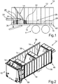
- a push-off carriage 10 designed as a trailer is shown in a schematic, partially transparent side view in FIG Fig. 1 shown.
- the push-off carriage 10 comprises a chassis 11, only indicated schematically here, on or on which a push-off device 12 is accommodated.
- the push-off device 12 comprises a push-off wall 14 which can be moved relative to a sliding floor 16, which in turn can be moved relative to a loading floor 18.
- the push-off device 12 comprises a first hydraulic cylinder arrangement 20, which has a first hydraulic cylinder piston 24 movable in a first hydraulic cylinder tube 22.
- the pushing-off device 12 also comprises a second hydraulic cylinder arrangement 26, which comprises a second hydraulic cylinder piston 30 movable in a second hydraulic cylinder tube 28.
- the push-off wall 14 is mounted on the second hydraulic cylinder tube 28 by means of two sliding elements 32, 34.
- Fig. 2 the push-off device 12 without the undercarriage 11 is shown in a perspective view.
- the push-off wall 14 is shown in three different positions; contrary to the present illustration, the push-off device has 12 so of course only a single sliding wall 14.
- the push-off device 12 furthermore comprises a loading space 36 which is clearly recognizable here and which is formed by the loading floor 18, two side walls 38 adjoining it laterally and the displaceable push-off wall 14. In the area of a front edge 40 of the loading floor 18, the loading space 36 can also be closed by a pivotable flap 42.
- the push-off wall 14 can therefore be moved in the longitudinal direction x of the loading space 36.
- the push-off wall 14 can be pushed forwards until an unloading position until the push-off wall 14 has reached the area of the front edge 40 of the loading floor 18.
- transported goods for example agricultural bulk goods or the like
- received in the loading space 36 by means of the push-off device 12 can be conveyed down from the loading floor 18 in a particularly simple manner.
- the push-off wall 14 can also be pushed back until the push-off wall 14 is located in the region of a rear edge 44 of the loading floor 18.
- Fig. 3 the push-off device 12 is shown in a partially transparent side view, the push-off wall 14 being arranged in its loading position, so that the loading space 36 is maximized.
- the two hydraulic cylinder pistons 24, 30 are completely inserted into the respective hydraulic cylinder tubes 22, 28, which is also the reason why the hydraulic cylinder pistons 24, 30 are not visible in the present illustration.
- Fig. 4 the push-off wall 14 is shown in its unloading position, in which the push-off wall 14 has been moved up to the front edge 40 of the loading floor 18.
- the two hydraulic cylinder pistons 24, 30 are fully extended. The maximum travel of the push-off wall 14 thus results from the addition of the respective strokes of the hydraulic cylinder arrangements 20, 26.
- first hydraulic cylinder tube 22 is fastened to the second hydraulic cylinder tube 28.
- the first hydraulic cylinder tube 22 and the second hydraulic cylinder tube 28 are fastened to one another at respective longitudinal ends 46, 48, from which the respective hydraulic cylinder pistons 24, 30 can be extended.
- first hydraulic cylinder piston 24 and the second hydraulic cylinder piston 30 are arranged such that they can be extended in opposite directions to one another.
- the two hydraulic cylinder tubes 22, 28 are fastened to one another by means of a radial spacer 50.
- the hydraulic cylinder pistons 24, 30 are spaced apart from the respective hydraulic cylinder tubes 22, 28 in the radial direction, or in other words in the vertical direction, of the push-off device 12, so that the hydraulic cylinder pistons 24, 30 can be extended and retracted without collision.
- the first hydraulic cylinder piston 24 is in turn attached to the push-off wall 14.
- the first hydraulic cylinder arrangement 20 is thus supported on the second hydraulic cylinder tube 28 and can thus move the push-off wall 14 relative to the push-off floor 16 by extending and retracting the first hydraulic cylinder piston 24.
- the second hydraulic cylinder piston 30 is attached to the immovable loading floor 18, the second hydraulic cylinder tube 28 being attached to the sliding floor 16.
- the second hydraulic cylinder piston 30 is therefore not relatively movable relative to the loading space 36 or to the immovable loading floor 18. Instead, by appropriately loading a hydraulic medium, the second hydraulic cylinder tube 28 can be moved relative to the immovable loading floor 18 of the loading space 36 and thereby move the movable sliding floor 16 relative to the loading floor 18.
- the push-off wall 14 is mounted on the second hydraulic cylinder tube 28, the push-off wall 14 is automatically moved in the longitudinal direction x of the loading space 36 as soon as the second hydraulic cylinder piston 30 is extended or retracted, as a result of which the second hydraulic cylinder tube 28 is moved in the longitudinal direction x.
- a bearing element 52 which extends in the radial direction from the second hydraulic cylinder piston 30, is attached underneath at a free end the switching of which the second hydraulic cylinder piston 30 is fastened to the loading floor 18 of the loading space 36.
- the bearing element 52 helps to ensure that the second hydraulic cylinder piston 30 does not touch the loading floor 18 and can thus be moved in and out without collision.
- Fig. 5 the mounting of the push-off wall 14 on the second hydraulic cylinder tube 28 is shown in a schematic side sectional view.
- the two sliding elements 32, 34 which at least partially enclose the second hydraulic cylinder tube 28 on the outer circumference, can again be clearly seen here.
- the two sliding elements 32, 34 are arranged somewhat spaced apart in the axial direction, that is to say in the longitudinal direction x, so that the push-off wall 14 is mounted in a stable manner and any tilting moments due to the eccentric application of force to the push-off wall 14 can be absorbed.
- the second hydraulic cylinder tube 28 On the front side at a closed end of the second hydraulic cylinder tube 28 there is attached a bearing element 54 which extends in the radial direction and by means of which the second hydraulic cylinder tube 28 is fastened to the sliding floor 16.
- the bearing element 54 By means of the bearing element 54, the second hydraulic cylinder tube 28 can be arranged so far from the sliding floor 16 that the sliding elements 32, 34 can be moved relatively along the second hydraulic cylinder tube 28 without touching the sliding floor 16.
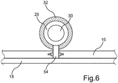
- Fig. 6 the storage of the push-off wall 14 is again shown schematically in a partially sectioned frontal view.
- the concentric arrangement of the sliding element 32, the second hydraulic cylinder tube 28 and the second hydraulic cylinder piston 30 can again be clearly seen.
- the bearing element 54 can be welded to both the second hydraulic cylinder tube 28 and the sliding floor 16, for example.
- other fastening options such as screw connections or the like, can also be used to connect the second hydraulic cylinder tube 28 to the sliding floor 16.
Landscapes
- Engineering & Computer Science (AREA)
- Mechanical Engineering (AREA)
- Transportation (AREA)
- Reciprocating Conveyors (AREA)
- Actuator (AREA)
- Agricultural Machines (AREA)
- Loading Or Unloading Of Vehicles (AREA)
Description
- Die Erfindung betrifft eine Abschiebevorrichtung der im Oberbegriff des Patentanspruchs 1 angegebenen Art. Des Weiteren betrifft die Erfindung noch einen Abschiebewagen mit einer Abschiebevorrichtung.
- Die
EP 1 609 668 A2 zeigt einen als Abschiebewagen ausgebildeten Anhänger mit einer Abschiebevorrichtung. Die Abschiebevorrichtung dient insbesondere zum Aufnehmen und zum Entladen von landwirtschaftlichem Transportgut. Die Abschiebevorrichtung umfasst einen Laderaum, welcher einen Ladeboden, zwei seitlich daran angrenzende Seitenwände und eine Abschiebwand aufweist. Die Abschiebewand ist dabei in Längsrichtung des Laderaums relativ zu einem Schiebeboden verschiebbar, der seinerseits in Längsrichtung des Laderaums relativ zum Ladeboden des Laderaums verschiebbar ist. Die Abschiebewand kann dabei mittels einer Gewindespindel relativ zum Schiebeboden verschoben werden, wobei der Schiebeboden wiederum mittels einer Zylinderkolbenanordnung relativ zum Ladeboden des Laderaums verschiebbar ist. Die Relativbeweglichkeit der Abschiebewand zum seinerseits verschiebbaren Schiebeboden wird dadurch ermöglicht, dass die Abschiebewand mittels Gleitelementen an einem Führungsprofil schlittenartig gelagert ist, welches die Gewindespindel umgibt. - Die
GB 2 036 687 A1 - Es ist die Aufgabe der vorliegenden Erfindung, eine Abschiebevorrichtung der eingangs genannten Art bereitzustellen, welche einen besonders einfachen Aufbau aufweist.
- Diese Aufgabe wird durch eine Abschiebevorrichtung mit den Merkmalen des Patentanspruchs 1 gelöst. Vorteilhafte Ausgestaltungen mit zweckmäßigen und nicht trivialen Weiterbildungen der Erfindung sind in den abhängigen Ansprüchen angegeben.
- Die erfindungsgemäße Abschiebevorrichtung, insbesondere für landwirtschaftliches Transportgut, umfasst einen Laderaum, welcher einen Ladeboden, zwei seitlich daran angrenzende Seitenwände und eine Abschiebwand aufweist. Die Abschiebewand ist dabei in Längsrichtung des Laderaums relativ zu einem Schiebeboden verschiebbar, der seinerseits in Längsrichtung des Laderaums relativ zum Ladeboden des Laderaums verschiebbar ist. Um einen besonders einfachen Aufbau der Abschiebevorrichtung zu realisieren, ist es erfindungsgemäß vorgesehen, dass die Abschiebevorrichtung eine erste Hydraulikzylinderanordnung aufweist, welche zumindest einen in einem ersten Hydraulikzylinderrohr bewegbaren ersten Hydraulikzylinderkolben umfasst. Ferner ist es erfindungsgemäß vorgesehen, dass die Abschiebevorrichtung eine zweite Hydraulikzylinderanordnung aufweist, welche zumindest einen in einem zweiten Hydraulikzylinderrohr beweglichen zweiten Hydraulikzylinderkolben umfasst. Es ist auch möglich, dass die erste und/oder die zweite Hydraulikzylinderanordnung mehrere Hydraulikzylinderrohre und Hydraulikzylinderkolben aufweist. Bei der ersten Hydraulikzylinderanordnung und/oder bei der zweiten Hydraulikzylinderanordnung kann es sich also auch um ein Zylinderpaket handeln. Die Abschiebewand ist erfindungsgemäß in Längsrichtung des Laderaums verschiebbar am zweiten Hydraulikzylinderrohr gelagert und mittels der ersten Hydraulikzylinderanordnung relativ zum Schiebeboden verschiebbar, der mittels der zweiten Hydraulikzylinderanordnung relativ zum Ladeboden des Laderaums verschiebbar ist. Vorzugsweise sind die Hydraulikzylinderrohre und die Hydraulikzylinderkolben parallel zum Ladeboden ausgerichtet, wobei die Haupterstreckungsrichtung der Hydraulikzylinderrohre und der Hydraulikzylinderkolben in Längsrichtung der Abschiebevorrichtung und somit auch in Längsrichtung des Laderaums verläuft.
- Mittels der beiden Hydraulikzylinderanordnungen ist es also möglich, die Abschiebwand zwischen einer eingefahrenen Beladeposition und einer ausgefahrenen Entladeposition hin und her zu verschieben. Die eingefahrene Beladeposition wird eingenommen, wenn beide Hydraulikzylinderkolben vollständig eingefahren worden sind, wobei die ausgefahrene Entladeposition eingenommen wird, wenn beide Hydraulikzylinderkolben vollständig ausgefahren worden sind. Vorzugsweise befindet sich die Abschiebewand in der ausgefahrenen Entladeposition im Bereich einer Vorderkante des Ladebodens des Laderaums, sodass im Laderaum aufgenommenes Transportgut mittels der Abschiebewand vom Ladeboden heruntergeschoben werden kann. In der eingefahrenen Beladeposition befindet sich hingegen die Abschiebewand vorzugsweise gegenüberliegend von der Vorderkante des Ladebodens im Bereich einer Hinterkante des Ladebodens, sodass in der Beladeposition der größtmöglich bereitstellbare Laderaum durch eine entsprechende Positionierung der Abschiebewand bereitgestellt wird.
- Um einen besonders einfachen Aufbau bei der Abschiebevorrichtung zu realisieren, ist es vorgesehen, dass das zweite Hydraulikzylinderrohr als Linearführung für die translatorische Bewegung der Abschiebewand dient. Im Gegensatz zu der in der
EP 1 609 668 A2 gezeigten Abschiebevorrichtung ist also kein separates Führungsprofil mehr notwendig, um die translatorische Relativbewegung der Abschiebewand gegenüber dem seinerseits verschiebbaren Schiebeboden zu realisieren. Da zusätzliche Führungsprofile bzw. Führungsschienen aufgrund der Linearführungsfunktion des zweiten Hydraulikzylinders eingespart werden können, kann entsprechend viel Gewicht bei der Abschiebevorrichtung eingespart werden. Aufgrund der verringerten Teileanzahl gestaltet sich auch der Fertigungsaufwand bei der erfindungsgemäßen Abschiebevorrichtung wesentlich günstiger als beim eingangs zitierten Stand der Technik. Darüber hinaus werden auch weniger bewegliche Hydraulikschläuche benötigt, wobei letztlich auch noch die Abschiebevorrichtung insgesamt optisch ansprechender gestaltet werden kann. Vorzugsweise ist die erste Hydraulikzylinderanordnung in Hochrichtung der Abschiebevorrichtung oberhalb von der zweiten Hydraulikzylinderanordnung angeordnet. - Eine vorteilhafte Ausführungsform der Erfindung sieht vor, dass das erste Hydraulikzylinderrohr am zweiten Hydraulikzylinderrohr und der erste Hydraulikzylinderkolben an der Abschiebewand befestigt ist. Vorzugsweise dient also das zweite Hydraulikzylinderrohr nicht nur als Linearführung für die translatorische Bewegung der Abschiebewand sondern zusätzlich auch noch zur Befestigung des ersten Hydraulikzylinderrohrs. Aufgrund dieser zusätzlichen Funktionsintegration im Hinblick auf das zweite Hydraulikzylinderrohr können nochmals Teile und somit auch Gewicht bei der Abschiebevorrichtung eingespart werden. Die erste Hydraulikzylinderanordnung stützt sich also vorzugsweise am zweiten Hydraulikzylinderrohr ab und kann somit durch Aus- und Einfahren des ersten Hydraulikzylinderkolbens die Abschiebewand relativ zum Abschiebeboden bewegen.
- Eine weitere vorteilhafte Ausführungsform der Erfindung sieht vor, dass der zweite Hydraulikzylinderkolben am Ladeboden des Laderaums und das zweite Hydraulikzylinderrohr am Schiebeboden befestigt ist. Die zweite Hydraulikzylinderanordnung stützt sich also am unbeweglichen Ladeboden ab und kann somit durch Aus- und Einfahren des zweiten Hydraulikzylinderkolbens den Abschiebeboden relativ zum Ladeboden bewegen. Da der zweite Hydraulikzylinderkolben am unbeweglichen Ladeboden befestigt ist, bewegt sich also bei der zweiten Hydraulikzylinderanordnung das zweite Hydraulikzylinderrohr relativ zum Ladeboden, wenn der zweite Hydraulikzylinderkolben aus- bzw. eingefahren wird. Beim Bewegen des Schiebebodens wird dann also zwangsläufig auch die Abschiebewand relativ zum Ladeboden und den Seitenwänden bewegt. Um eine besonders einfache Ansteuerung der beiden Hydraulikzylinderanordnungen zu realisieren, kann es dabei vorgesehen sein, dass diese gleichzeitig aus demselben Kreislauf mit einem Hydraulikmedium druckbeaufschlagt werden. Je nach auftretenden Bewegungswiderständen im Hinblick auf die Verschiebung der Abschiebewand und des Schiebebodens werden dann die jeweiligen Hydraulikzylinderkolben unter Umständen unterschiedlich schnell ausgefahren und eingefahren bis diese ihre jeweiligen Endlagen erreicht haben.
- In weiterer vorteilhafter Ausgestaltung der Erfindung ist es vorgesehen, dass stirnseitig an einem geschlossenen Ende des zweiten Hydraulikzylinderrohrs ein sich in radialer Richtung erstreckendes Lagerelement angebracht ist, unter dessen Vermittlung das zweite Hydraulikzylinderrohr am Schiebeboden befestigt ist. Beispielsweise kann das Lagerelement sowohl am zweiten Hydraulikzylinderrohr als auch am Schiebeboden angeschweißt sein. Andere Befestigungsmöglichkeiten des zweiten Hydraulikrohrs an dem Schiebeboden sind aber ebenfalls möglich.
- In weiterer vorteilhafter Ausgestaltung der Erfindung ist es vorgesehen, dass stirnseitig an einem freien Ende des zweiten Hydraulikzylinderkolbens ein sich in radialer Richtung erstreckendes Lagerelement angebracht ist, unter dessen Vermittlung der zweite Hydraulikzylinderkolben am Ladeboden des Laderaums befestigt ist. Das Lagerelement kann beispielsweise am Ladeboden und am freien Ende des zweiten Hydraulikzylinderkolbens angeschweißt oder auch anderweitig befestigt sein. In jedem Fall wird der zweite Hydraulikzylinderkolben vorzugsweise parallel zum Ladeboden ausgerichtet und entsprechend beabstandet, sodass der der zweite Hydraulikzylinderkolben beim Einfahren und Ausfahren nicht den Ladeboden berührt.
- Gemäß einer weiteren vorteilhaften Ausführungsform der Erfindung ist es vorgesehen, dass der erste Hydraulikzylinderkolben und der zweite Hydraulikzylinderkolben gegenläufig zueinander ausfahrbar angeordnet sind. Vorzugsweise weist der zweite Hydraulikzylinderkolben eine in axialer Richtung verlaufende Innenbohrung zur Versorgung der zweiten Hydraulikzylinderanordnung mit einer Hydraulikflüssigkeit auf. Durch die gegenläufige Ausfahrbarkeit der beiden Hydraulikzylinderkolben wird auf einfache Weise ermöglicht, das zweite Hydraulikzylinderrohr am ersten Hydraulikzylinderrohr zu befestigen und das zweite Hydraulikzylinderrohr als Linearführung für die Abschiebewand zu verwenden.
- Eine weitere vorteilhafte Ausführungsform der Erfindung sieht vor, dass das erste Hydraulikzylinderrohr und das zweite Hydraulikzylinderrohr an jeweiligen Längsenden aneinander befestigt sind, aus welchen jeweilige Hydraulikzylinderkolben ausfahrbar sind. Dies ist insbesondere dann sinnvoll, wenn die beiden Hydraulikzylinderkolben gegenläufig ausfahrbar angeordnet sind, da bei dieser Anordnung der maximale Hub durch Ein- und Ausfahren der jeweiligen Hydraulikzylinderkolben erzielt werden kann.
- In weiterer vorteilhafter Ausgestaltung der Erfindung ist es vorgesehen, dass die Abschiebewand mittels wenigstens einem Gleitelement, welches das zweite Hydraulikzylinderrohr zumindest teilweise außenumfangsseitig umschließt, am zweiten Hydraulikzylinderrohr gelagert ist. Vorzugsweise ist die Abschiebewand mittels eines weiteren Gleitelements, welches das zweite Hydraulikzylinderrohr ebenfalls zumindest teilweise außenumfangsseitig umschließt und vom anderen Gleitelement in axialer Richtung beabstandet ist, am zweiten Hydraulikzylinderrohr gelagert. Die beiden Gleitelemente dienen also als eine Art Schlitten, mittels welchem die Abschiebewand verschiebbar am zweiten Hydraulikzylinderrohr beweglich gelagert ist. Beispielsweise kann das zweite Hydraulikzylinderrohr dabei in radialer Richtung soweit von dem Schiebeboden entfernt angeordnet sein, dass die beiden Gleitelemente das zweite Hydraulikzylinderrohr vollständig umschließen können. In einem derartigen Fall kann eine besonders stabile Gleitlagerung der Abschiebewand am zweiten Hydraulikzylinderrohr realisiert werden.
- Der erfindungsgemäße Abschiebewagen umfasst die erfindungsgemäße Abschiebevorrichtung oder eine vorteilhafte Ausführungsform der erfindungsgemäßen Abschiebevorrichtung. Bei dem Abschiebewagen kann es sich beispielsweise um einen Anhänger handeln, welcher von einem Zugfahrzeug, wie beispielsweise einem Traktor oder auch von einem LKW gezogen werden kann. Alternativ ist es aber auch möglich, dass die Abschiebevorrichtung als Teil eines Containers, wie beispielsweise eines Isocontainers oder dergleichen realisiert wird.
- Weitere Vorteile, Merkmale und Einzelheiten der Erfindung ergeben sich aus der nachfolgenden Beschreibung eines bevorzugten Ausführungsbeispiels sowie anhand der Zeichnung. Die vorstehend in der Beschreibung genannten Merkmale und Merkmalskombinationen sowie die nachfolgend in der Figurenbeschreibung genannten und/oder in den Figuren alleine gezeigten Merkmale und Merkmalskombinationen sind nicht nur in der angegebenen Kombination sondern auch in Alleinstellung verwendbar, ohne den Rahmen der Erfindung zu verlassen.
- Die Zeichnung zeigt in:
- Fig. 1
- eine teiltransparente schematische Seitenansicht eines als Anhänger ausgebildeten Abschiebewagens mit einer Abschiebevorrichtung, welche einen Laderaum aufweist, der einen Ladeboden, zwei seitlich daran angrenzende Seitenwände und eine Abschiebewand umfasst, welche in Längsrichtung des Laderaums relativ zu einem Schiebeboden verschiebbar ist, der seinerseits in Längsrichtung des Laderaums relativ zum Ladeboden des Laderaums verschiebbar ist;
- Fig. 2
- eine Perspektivansicht der Abschiebevorrichtung, wobei die Abschiebewand an drei verschiedenen Positionen angeordnet dargestellt ist;
- Fig. 3
- eine teiltransparente Seitenansicht der Abschiebevorrichtung, wobei die Abschiebewand in einer vollständig eingefahrenen Beladeposition angeordnet ist;
- Fig. 4
- eine teiltransparente Seitenansicht der Abschiebevorrichtung, wobei die Abschiebewand in einer ausgefahrenen Entladeposition angeordnet ist, in welcher sich die Abschiebewand an einer Vorderkante des Ladebodens des Laderaums befindet;
- Fig. 5
- eine teilweise geschnittene Detailansicht der Lagerung der Abschiebewand; und in
- Fig. 6
- eine teilweise geschnittene Frontalansicht, in welcher erneut die Lagerung der Abschiebewand schematisch dargestellt ist.
- In den Figuren werden gleiche oder funktionsgleiche Elemente mit gleichen Bezugszeichen versehen.
- Ein als Anhänger ausgebildeter Abschiebewagen 10 ist in einer schematischen teiltransparenten Seitenansicht in
Fig. 1 gezeigt. Der Abschiebewagen 10 umfasst ein hier nur schematisch angedeutetes Fahrwerk 11, an bzw. auf welchem eine Abschiebevorrichtung 12 aufgenommen ist. Die Abschiebevorrichtung 12 umfasst eine Abschiebewand 14, welche relativ zu einem Schiebeboden 16 verschiebbar ist, der seinerseits relativ zu einem Ladeboden 18 verschiebbar ist. Zum Verschieben der Abschiebewand 14 umfasst die Abschiebevorrichtung 12 eine erste Hydraulikzylinderanordnung 20, welche einen in einem ersten Hydraulikzylinderrohr 22 beweglichen ersten Hydraulikzylinderkolben 24 aufweist. Zum Verschieben des Schiebebodens 16 umfasst die Abschiebevorrichtung 12 darüber hinaus noch eine zweite Hydraulikzylinderanordnung 26, welche einen in einem zweiten Hydraulikzylinderrohr 28 beweglichen zweiten Hydraulikzylinderkolben 30 umfasst. Die Abschiebewand 14 ist dabei mittels zweier Gleitelemente 32, 34 am zweiten Hydraulikzylinderrohr 28 gelagert. - In
Fig. 2 ist die Abschiebevorrichtung 12 ohne das Fahrwerk 11 in einer Perspektivansicht dargestellt. Die Abschiebwand 14 ist dabei in drei verschiedenen Positionen dargestellt, entgegen der vorliegenden Darstellung weist die Abschiebvorrichtung 12 also natürlich nur eine einzige Abschiebewand 14 auf. Die Abschiebevorrichtung 12 umfasst des Weiteren einen hier gut erkennbaren Laderaum 36, welcher durch den Ladeboden 18, zwei seitlich daran angrenzende Seitenwände 38 und die verschiebbare Abschiebewand 14 gebildet wird. Im Bereich einer Vorderkante 40 des Ladebodens 18 kann der Laderaum 36 zudem durch eine verschwenkbare Klappe 42 verschlossen werden. - Wie vorliegend zu erkennen, kann die Abschiebewand 14 also in Längsrichtung x des Laderaums 36 verschoben werden. Die Abschiebewand 14 kann dabei bis zu einer Entladeposition so weit nach vorne verschoben werden, bis die Abschiebewand 14 im Bereich der Vorderkante 40 des Ladebodens 18 angelangt ist. Dadurch kann mittels der Abschiebevorrichtung 12 im Laderaum 36 aufgenommenes Transportgut, beispielsweise landwirtschaftliches Schüttgut oder dergleichen, auf besonders einfache Weise vom Ladeboden 18 hinunterbefördert werden. Des Weiteren kann die Abschiebewand 14 auch so weit nach hinten verschoben werden, bis sich die Abschiebewand 14 im Bereich einer Hinterkante 44 des Ladebodens 18 befindet.
- In
Fig. 3 ist die Abschiebevorrichtung 12 in einer teiltransparenten Seitenansicht gezeigt, wobei die Abschiebewand 14 in ihrer Beladeposition angeordnet ist, sodass der Laderaum 36 maximiert ist. In dieser Positionierung der Abschiebewand 14 sind die beiden Hydraulikzylinderkolben 24, 30 vollständig in die jeweiligen Hydraulikzylinderrohre 22, 28 eingefahren, was auch der Grund dafür ist, dass in der vorliegenden Darstellung die Hydraulikzylinderkolben 24, 30 nicht sichtbar sind. - In
Fig. 4 ist die Abschiebewand 14 in ihrer Entladeposition gezeigt, in welcher die Abschiebewand 14 bis an die Vorderkante 40 des Ladebodens 18 bewegt worden ist. In dieser Stellung bzw. Positionierung der Abschiebewand 14 sind die beiden Hydraulikzylinderkolben 24, 30 vollständig ausgefahren. Der maximale Verfahrweg der Abschiebewand 14 ergibt sich also durch Addition der jeweiligen Hübe der Hydraulikzylinderanordnungen 20, 26. - Wie zu erkennen, ist das erste Hydraulikzylinderrohr 22 am zweiten Hydraulikzylinderrohr 28 befestigt. Das erste Hydraulikzylinderrohr 22 und das zweite Hydraulikzylinderrohr 28 sind dabei an jeweiligen Längsenden 46, 48 aneinander befestigt, aus welchen die jeweiligen Hydraulikzylinderkolben 24, 30 ausfahrbar sind. Wie zu erkennen sind dabei der erste Hydraulikzylinderkolben 24 und der zweite Hydraulikzylinderkolben 30 gegenläufig zueinander ausfahrbar angeordnet. Um die Ausfahr- und Einfahrbewegung der jeweiligen Hydraulikzylinderkolben 24, 30 nicht zu beeinträchtigen, sind die beiden Hydraulikzylinderrohre 22, 28 unter Vermittlung eines radialen Abstandshalters 50 aneinander befestigt. Dadurch sind die Hydraulikzylinderkolben 24, 30 in radialer Richtung, oder anders ausgedrückt in Hochrichtung der Abschiebevorrichtung 12, soweit von den jeweiligen Hydraulikzylinderrohren 22, 28 beabstandet, dass die Hydraulikzylinderkolben 24, 30 kollisionsfrei aus- und eingefahren werden können.
- Der erste Hydraulikzylinderkolben 24 ist wiederum an der Abschiebewand 14 befestigt. Die erste Hydraulikzylinderanordnung 20 stützt sich also am zweiten Hydraulikzylinderrohr 28 ab, und kann somit durch Aus- und Einfahren des ersten Hydraulikzylinderkolbens 24 die Abschiebewand 14 relativ zum Abschiebeboden 16 bewegen. Der zweite Hydraulikzylinderkolben 30 ist am unbeweglichen Ladeboden 18 befestigt, wobei das zweite Hydraulikzylinderrohr 28 am Schiebeboden 16 befestigt ist. Der zweite Hydraulikzylinderkolben 30 ist also zum Laderaum 36 bzw. zum unbeweglichen Ladeboden 18 nicht relativbeweglich. Stattdessen kann durch eine entsprechende Beaufschlagung mit einem Hydraulikmedium das zweite Hydraulikzylinderrohr 28 relativ zum unbeweglichen Ladeboden 18 des Laderaums 36 bewegt werden und dadurch den beweglichen Schiebeboden 16 relativ zum Ladeboden 18 bewegen. Da die Abschiebewand 14 am zweiten Hydraulikzylinderrohr 28 gelagert ist, wird die Abschiebewand 14 automatisch in Längsrichtung x des Laderaums 36 mitbewegt, sobald der zweite Hydraulikzylinderkolben 30 aus- bzw. eingefahren wird, in Folge dessen das zweite Hydraulikzylinderrohr 28 in Längsrichtung x bewegt wird.
- Stirnseitig an einem freien Ende des zweiten Hydraulikzylinderkolbens 30 ist ein sich in radialer Richtung von diesem erstreckendes Lagerelement 52 angebracht, unter dessen Vermittlung der zweite Hydraulikzylinderkolben 30 am Ladeboden 18 des Laderaums 36 befestigt ist. Das Lagerelement 52 trägt dazu bei, dass der zweite Hydraulikzylinderkolben 30 den Ladeboden 18 nicht berührt und somit kollisionsfrei ein- und ausgefahren werden kann.
- In
Fig. 5 ist die Lagerung der Abschiebewand 14 am zweiten Hydraulikzylinderrohr 28 in einer schematischen Seitenschnittansicht dargestellt. Hier sind nochmals gut die beiden Gleitelemente 32, 34 zu erkennen, welche das zweite Hydraulikzylinderrohr 28 zumindest teilweise außenumfangsseitig umschließen. Die beiden Gleitelemente 32, 34 sind dabei in axialer Richtung, also in Längsrichtung x, etwas voneinander beabstandet angeordnet, sodass die Abschiebewand 14 stabil gelagert ist und etwaige Kippmomente aufgrund der exzentrischen Kraftbeaufschlagung der Abschiebewand 14 aufgefangen werden können. - Stirnseitig an einem geschlossenen Ende des zweiten Hydraulikzylinderrohrs 28 ist ein sich in radialer Richtung erstreckendes Lagerelement 54 angebracht, unter dessen Vermittlung das zweite Hydraulikzylinderrohr 28 am Schiebeboden 16 befestigt ist. Durch das Lagerelement 54 kann das zweite Hydraulikzylinderrohr 28 so weit von dem Schiebeboden 16 beabstandet angeordnet werden, dass die Gleitelemente 32, 34 relativ entlang des zweiten Hydraulikzylinderrohrs 28 bewegt werden können ohne den Schiebeboden 16 zu berühren.
- In
Fig. 6 ist die Lagerung der Abschiebewand 14 in einer teilweise geschnittenen Frontalansicht nochmals schematisch dargestellt. In der vorliegenden Darstellung ist nochmals gut die konzentrische Anordnung des Gleitelements 32, des zweiten Hydraulikzylinderrohrs 28 und des zweiten Hydraulikzylinderkolbens 30 zu erkennen. Das Lagerelement 54 kann beispielsweise sowohl am zweiten Hydraulikzylinderrohr 28 als auch am Schiebeboden 16 angeschweißt sein. Es können aber auch andere Befestigungsmöglichkeiten, wie beispielsweise Verschraubungen oder dergleichen eingesetzt werden, um das zweite Hydraulikzylinderrohr 28 mit dem Schiebeboden 16 zu verbinden. -
- 10
- Abschiebewagen
- 11
- Fahrwerk
- 12
- Abschiebevorrichtung
- 14
- Abschiebewand
- 16
- Schiebeboden
- 18
- Ladeboden
- 20
- erste Hydraulikzylinderanordnung
- 22
- erstes Hydraulikzylinderrohr
- 24
- erster Hydraulikzylinderkolben
- 26
- zweite Hydraulikzylinderanordnung
- 28
- zweites Hydraulikzylinderrohr
- 30
- zweiter Hydraulikzylinderkolben
- 32
- Gleitelement
- 34
- Gleitelement
- 36
- Laderaum
- 38
- Seitenwand
- 40
- Vorderkante
- 42
- verschwenkbare Klappe
- 44
- Hinterkante
- 46
- Längsende
- 48
- Längsende
- 50
- Abstandshalter
- 52
- Lagerelement
- 54
- Lagerelement
- x
- Längsrichtung
Claims (10)
- Abschiebevorrichtung (12), insbesondere für landwirtschaftliches Transportgut, umfassend einen Laderaum (36), welcher einen Ladeboden (18), zwei seitlich daran angrenzende Seitenwände (38) und eine Abschiebewand (14) aufweist, welche in Längsrichtung (x) des Laderaums (36) relativ zu einem Schiebeboden (16) verschiebbar ist, der seinerseits in Längsrichtung (x) des Laderaums (36) relativ zum Ladeboden (18) des Laderaums (36) verschiebbar ist; wobei- die Abschiebevorrichtung (12) eine erste Hydraulikzylinderanordnung (20) aufweist, welche zumindest einen in einem ersten Hydraulikzylinderohr (22) beweglichen ersten Hydraulikzylinderkolben (24) umfasst;- die Abschiebevorrichtung (12) eine zweite Hydraulikzylinderanordnung (26) aufweist, welche zumindest einen in einem zweiten Hydraulikzylinderohr (28) beweglichen zweiten Hydraulikzylinderkolben (30) umfasst;
dadurch gekennzeichnet, dass- die Abschiebewand (14) in Längsrichtung (x) des Laderaums (36) verschiebbar am zweiten Hydraulikzylinderohr (28) gelagert und mittels der ersten Hydraulikzylinderanordnung (20) relativ zum Schiebeboden (16) verschiebbar ist, der mittels der zweiten Hydraulikzylinderanordnung (26) relativ zum Ladeboden (18) des Laderaums (36) verschiebbar ist. - Abschiebevorrichtung (12) nach Anspruch 1,
dadurch gekennzeichnet, dass
das erste Hydraulikzylinderohr (22) am zweiten Hydraulikzylinderohr (28) und der erste Hydraulikzylinderkolben (24) an der Abschiebewand (14) befestigt ist. - Abschiebevorrichtung (12) nach Anspruch 1 oder 2,
dadurch gekennzeichnet, dass
der zweite Hydraulikzylinderkolben (30) am Ladeboden (18) des Laderaums (36) und das zweite Hydraulikzylinderohr (28) am Schiebeboden (16) befestigt ist. - Abschiebevorrichtung (12) nach Anspruch 3,
dadurch gekennzeichnet, dass
stirnseitig an einem geschlossenen Ende des zweiten Hydraulikzylinderohrs (28) ein sich in radialer Richtung erstreckendes Lagerelement (54) angebracht ist, unter dessen Vermittlung das zweite Hydraulikzylinderohr (28) am Schiebeboden (16) befestigt ist. - Abschiebevorrichtung (12) nach Anspruch 3 oder 4,
dadurch gekennzeichnet, dass
stirnseitig an einem freien Ende des zweiten Hydraulikzylinderkolbens (30) ein sich in radialer Richtung erstreckendes Lagerelement (52) angebracht ist, unter dessen Vermittlung der zweite Hydraulikzylinderkolben (30) am Ladeboden (18) des Laderaums (36) befestigt ist. - Abschiebevorrichtung (12) nach einem der vorhergehenden Ansprüche,
dadurch gekennzeichnet, dass
der erste Hydraulikzylinderkolben (24) und der zweite Hydraulikzylinderkolben (30) gegenläufig zueinander ausfahrbar angeordnet sind. - Abschiebevorrichtung (12) nach einem der vorhergehenden Ansprüche,
dadurch gekennzeichnet, dass
das erste Hydraulikzylinderohr (22) und das zweite Hydraulikzylinderohr (28) an jeweiligen Längsenden (46, 48) aneinander befestigt sind, aus welchen die jeweiligen Hydraulikzylinderkolben (24, 30) ausfahrbar sind. - Abschiebevorrichtung (12) nach einem der vorhergehenden Ansprüche,
dadurch gekennzeichnet, dass
die Abschiebewand (14) mittels wenigstens einem Gleitelement (32), welches das zweite Hydraulikzylinderohr (28) zumindest teilweise außenumfangsseitig umschließt, am zweiten Hydraulikzylinderohr (28) gelagert ist. - Abschiebevorrichtung (12) nach Anspruch 8,
dadurch gekennzeichnet, dass
die Abschiebewand (14) mittels eines weiteren Gleitelements (34), welches das zweite Hydraulikzylinderohr (28) zumindest teilweise außenumfangsseitig umschließt und vom anderen Gleitelement (32) in axialer Richtung beabstandet ist, am zweiten Hydraulikzylinderohr (28) gelagert ist. - Abschiebewagen (10) mit einer Abschiebevorrichtung (12) nach einem der vorhergehenden Ansprüche.
Priority Applications (2)
| Application Number | Priority Date | Filing Date | Title |
|---|---|---|---|
| SI201730365T SI3463975T1 (sl) | 2016-06-01 | 2017-02-17 | Potisna naprava in potisna prikolica s potisno napravo |
| PL17705882T PL3463975T3 (pl) | 2016-06-01 | 2017-02-17 | Urządzenie zsuwające oraz wóz zsuwający z urządzeniem zsuwającym |
Applications Claiming Priority (2)
| Application Number | Priority Date | Filing Date | Title |
|---|---|---|---|
| DE102016110138.9A DE102016110138B4 (de) | 2016-06-01 | 2016-06-01 | Abschiebevorrichtung und Abschiebewagen mit einer Abschiebevorrichtung |
| PCT/EP2017/053635 WO2017207120A1 (de) | 2016-06-01 | 2017-02-17 | Abschiebevorrichtung und abschiebewagen mit einer abschiebevorrichtung |
Publications (2)
| Publication Number | Publication Date |
|---|---|
| EP3463975A1 EP3463975A1 (de) | 2019-04-10 |
| EP3463975B1 true EP3463975B1 (de) | 2020-07-15 |
Family
ID=58057141
Family Applications (1)
| Application Number | Title | Priority Date | Filing Date |
|---|---|---|---|
| EP17705882.3A Active EP3463975B1 (de) | 2016-06-01 | 2017-02-17 | Abschiebevorrichtung und abschiebewagen mit einer abschiebevorrichtung |
Country Status (14)
| Country | Link |
|---|---|
| US (1) | US11180066B2 (de) |
| EP (1) | EP3463975B1 (de) |
| JP (1) | JP6770099B2 (de) |
| CN (1) | CN109415010B (de) |
| DE (1) | DE102016110138B4 (de) |
| ES (1) | ES2811376T3 (de) |
| HU (1) | HUE051668T2 (de) |
| NZ (1) | NZ748528A (de) |
| PH (1) | PH12018502510A1 (de) |
| PL (1) | PL3463975T3 (de) |
| RU (1) | RU2710521C1 (de) |
| SI (1) | SI3463975T1 (de) |
| UA (1) | UA123225C2 (de) |
| WO (1) | WO2017207120A1 (de) |
Families Citing this family (1)
| Publication number | Priority date | Publication date | Assignee | Title |
|---|---|---|---|---|
| DE102021120329A1 (de) | 2021-08-04 | 2023-02-09 | Deere & Company | Einlagerung von Erntegut in einem Silo |
Family Cites Families (18)
| Publication number | Priority date | Publication date | Assignee | Title |
|---|---|---|---|---|
| US3815764A (en) * | 1972-06-21 | 1974-06-11 | East Coast Equipment Corp | Load body with load compacting and ejecting blade |
| US3998343A (en) * | 1974-12-30 | 1976-12-21 | Fors Vernen E | Cargo moving apparatus for trucks |
| US4220280A (en) * | 1978-12-04 | 1980-09-02 | Deere & Company | Manure spreader |
| JPS58183324A (ja) * | 1982-04-22 | 1983-10-26 | Shin Meiwa Ind Co Ltd | スライドダンプの排出装置 |
| FR2542715B1 (fr) * | 1983-03-16 | 1987-11-06 | Saphem | Dispositif de compactage, notamment du contenu d'une caisse de semi-remorque de grande capacite |
| DE3869981D1 (de) * | 1987-01-22 | 1992-05-21 | John Barber | Fahrzeuge fuer guttransport. |
| DE29818105U1 (de) * | 1998-10-09 | 1998-12-24 | Fliegl, Josef, 84513 Töging | Abschiebeanhänger |
| US20050105993A1 (en) * | 2003-02-25 | 2005-05-19 | Hagenbuch Leroy | Rear eject body for haulage units |
| FR2862294B1 (fr) * | 2003-11-17 | 2006-12-08 | Philippe Legrand | Dispositif de dechargement par un bloc poussant du contenu d'une benne agricole |
| DE202004009744U1 (de) | 2004-06-21 | 2004-08-19 | Fliegl, Josef | Baueinheit für einen Anhänger |
| US7744330B2 (en) * | 2008-06-13 | 2010-06-29 | Blue Tee Corporation | Container packer system and method |
| CN201793199U (zh) * | 2010-07-23 | 2011-04-13 | 柳州延龙汽车有限公司 | 推卸式垃圾车 |
| CN202703377U (zh) * | 2012-07-10 | 2013-01-30 | 现代农装科技股份有限公司 | 一种剪式结构运棉模车 |
| CN203331902U (zh) * | 2013-06-05 | 2013-12-11 | 中国重汽集团青岛重工有限公司 | 二级卸货液压驱动装置 |
| CN203528369U (zh) * | 2013-10-29 | 2014-04-09 | 福州顺通道路救援服务有限公司 | 一种新型的拖运专项清障作业车 |
| DE202014105316U1 (de) * | 2014-11-05 | 2014-11-27 | Fliegl Agrartechnik Gmbh | Schiebewandsystem, Laderaumaufbau und Fahrzeug |
| IES86687B2 (en) | 2015-01-16 | 2016-08-10 | Kennedy John | Ejector and compactor system |
| BR102015017218A2 (pt) * | 2015-07-17 | 2016-03-08 | Fabrício Mendes Beltrame | sistema de pisos deslizantes e paredes de empurre, aplicados em caixas de cargas de semirreboques rodoviários, para descarregamento horizontal por estágios |
-
2016
- 2016-06-01 DE DE102016110138.9A patent/DE102016110138B4/de not_active Expired - Fee Related
-
2017
- 2017-02-17 EP EP17705882.3A patent/EP3463975B1/de active Active
- 2017-02-17 SI SI201730365T patent/SI3463975T1/sl unknown
- 2017-02-17 NZ NZ748528A patent/NZ748528A/en unknown
- 2017-02-17 ES ES17705882T patent/ES2811376T3/es active Active
- 2017-02-17 WO PCT/EP2017/053635 patent/WO2017207120A1/de not_active Ceased
- 2017-02-17 UA UAA201811209A patent/UA123225C2/uk unknown
- 2017-02-17 US US16/304,996 patent/US11180066B2/en active Active
- 2017-02-17 PL PL17705882T patent/PL3463975T3/pl unknown
- 2017-02-17 CN CN201780042202.4A patent/CN109415010B/zh active Active
- 2017-02-17 RU RU2018146434A patent/RU2710521C1/ru active
- 2017-02-17 JP JP2018562114A patent/JP6770099B2/ja active Active
- 2017-02-17 HU HUE17705882A patent/HUE051668T2/hu unknown
-
2018
- 2018-11-28 PH PH12018502510A patent/PH12018502510A1/en unknown
Non-Patent Citations (1)
| Title |
|---|
| None * |
Also Published As
| Publication number | Publication date |
|---|---|
| JP6770099B2 (ja) | 2020-10-14 |
| NZ748528A (en) | 2020-07-31 |
| EP3463975A1 (de) | 2019-04-10 |
| US11180066B2 (en) | 2021-11-23 |
| PH12018502510A1 (en) | 2019-09-30 |
| HUE051668T2 (hu) | 2021-03-29 |
| JP2019518650A (ja) | 2019-07-04 |
| WO2017207120A1 (de) | 2017-12-07 |
| US20200215953A1 (en) | 2020-07-09 |
| RU2710521C1 (ru) | 2019-12-26 |
| CN109415010A (zh) | 2019-03-01 |
| UA123225C2 (uk) | 2021-03-03 |
| CN109415010B (zh) | 2021-06-29 |
| ES2811376T3 (es) | 2021-03-11 |
| DE102016110138B4 (de) | 2020-07-09 |
| PL3463975T3 (pl) | 2020-11-16 |
| SI3463975T1 (sl) | 2020-12-31 |
| DE102016110138A1 (de) | 2017-12-07 |
Similar Documents
| Publication | Publication Date | Title |
|---|---|---|
| DE3880958T2 (de) | Gabeleinheit fuer hubwagen. | |
| WO1998054081A1 (de) | Kran mit einem teleskopausleger | |
| DE2948715C2 (de) | Streuwagen für auszustreuendes Gut, insbesondere Dünger | |
| DE69102385T2 (de) | Montagevorrichtung für eine parallel zum Chassis eines Fahrzeuges ausfahrbare Ladebordwand. | |
| EP1162111B1 (de) | Ladebordwandsystem mit Schiebeeinheit | |
| DE2052565A1 (de) | Vorrichtung an, mit zwei m einen Rahmen ein und ausfahrbar angeordneten Gabelschenkeln versehener Hubgabel aus gerüsteten Gabelstaplern | |
| EP2953887B1 (de) | Vorrichtung zur aufnahme und zum transport von lasten | |
| DE102016110138B4 (de) | Abschiebevorrichtung und Abschiebewagen mit einer Abschiebevorrichtung | |
| DE202005012049U1 (de) | Teleskopierbarer Schiebeholm | |
| EP2614028B1 (de) | Vorrichtung zur aufnahme eines gabelträgerprofils | |
| EP3118058A1 (de) | Fahrzeugaufbau | |
| EP2138427B1 (de) | Lastaufnahmemittel zur Ein- und Auslagerung von Lasten an bzw. von Lagerplätzen einer Regalanordnung | |
| DE68905899T2 (de) | Gabelhubwagen mit vorschubmechanismus. | |
| EP0992396A2 (de) | Baueinheit für fahrbare Anhänger | |
| DE4105487A1 (de) | Gabelstapler | |
| DE102006042771B4 (de) | Fahrzeugrahmen und Verfahren zur Herstellung eines derartigen Fahrzeugrahmens | |
| EP2951118B1 (de) | Hubzylinder mit einer umlenkrollenvorrichtung für ein flurförderzeug | |
| EP1645462B1 (de) | Fahrzeug | |
| DE102021116218B4 (de) | Anbaugerät für ein Flurförderzeug | |
| EP3118057B1 (de) | System von gleitenden böden und schiebewänden, angewendet bei ladepritschen von strassen-sattelaufliegern zum horizontalen entladen in stufen | |
| DE29611565U1 (de) | Kraftfahrzeug mit Schüttgutmulde | |
| DE102022125668A1 (de) | Schubmaststapler | |
| DE202026100598U1 (de) | Staplerhalterung mit beweglichem Unterfahrschutz | |
| EP2072453B1 (de) | Abstützvorrichtung | |
| WO2016042147A1 (de) | Lastkraftwagen mit einer hubeinrichtung für container |
Legal Events
| Date | Code | Title | Description |
|---|---|---|---|
| STAA | Information on the status of an ep patent application or granted ep patent |
Free format text: STATUS: UNKNOWN |
|
| STAA | Information on the status of an ep patent application or granted ep patent |
Free format text: STATUS: THE INTERNATIONAL PUBLICATION HAS BEEN MADE |
|
| PUAI | Public reference made under article 153(3) epc to a published international application that has entered the european phase |
Free format text: ORIGINAL CODE: 0009012 |
|
| STAA | Information on the status of an ep patent application or granted ep patent |
Free format text: STATUS: REQUEST FOR EXAMINATION WAS MADE |
|
| 17P | Request for examination filed |
Effective date: 20181023 |
|
| AK | Designated contracting states |
Kind code of ref document: A1 Designated state(s): AL AT BE BG CH CY CZ DE DK EE ES FI FR GB GR HR HU IE IS IT LI LT LU LV MC MK MT NL NO PL PT RO RS SE SI SK SM TR |
|
| AX | Request for extension of the european patent |
Extension state: BA ME |
|
| DAV | Request for validation of the european patent (deleted) | ||
| DAX | Request for extension of the european patent (deleted) | ||
| GRAP | Despatch of communication of intention to grant a patent |
Free format text: ORIGINAL CODE: EPIDOSNIGR1 |
|
| STAA | Information on the status of an ep patent application or granted ep patent |
Free format text: STATUS: GRANT OF PATENT IS INTENDED |
|
| INTG | Intention to grant announced |
Effective date: 20200304 |
|
| GRAS | Grant fee paid |
Free format text: ORIGINAL CODE: EPIDOSNIGR3 |
|
| GRAA | (expected) grant |
Free format text: ORIGINAL CODE: 0009210 |
|
| STAA | Information on the status of an ep patent application or granted ep patent |
Free format text: STATUS: THE PATENT HAS BEEN GRANTED |
|
| AK | Designated contracting states |
Kind code of ref document: B1 Designated state(s): AL AT BE BG CH CY CZ DE DK EE ES FI FR GB GR HR HU IE IS IT LI LT LU LV MC MK MT NL NO PL PT RO RS SE SI SK SM TR |
|
| REG | Reference to a national code |
Ref country code: GB Ref legal event code: FG4D Free format text: NOT ENGLISH Ref country code: CH Ref legal event code: EP |
|
| REG | Reference to a national code |
Ref country code: IE Ref legal event code: FG4D Free format text: LANGUAGE OF EP DOCUMENT: GERMAN |
|
| REG | Reference to a national code |
Ref country code: DE Ref legal event code: R096 Ref document number: 502017006202 Country of ref document: DE |
|
| REG | Reference to a national code |
Ref country code: AT Ref legal event code: REF Ref document number: 1290666 Country of ref document: AT Kind code of ref document: T Effective date: 20200815 |
|
| REG | Reference to a national code |
Ref country code: CH Ref legal event code: NV Representative=s name: VALIPAT S.A. C/O BOVARD SA NEUCHATEL, CH |
|
| REG | Reference to a national code |
Ref country code: LT Ref legal event code: MG4D |
|
| REG | Reference to a national code |
Ref country code: NL Ref legal event code: MP Effective date: 20200715 |
|
| PG25 | Lapsed in a contracting state [announced via postgrant information from national office to epo] |
Ref country code: FI Free format text: LAPSE BECAUSE OF FAILURE TO SUBMIT A TRANSLATION OF THE DESCRIPTION OR TO PAY THE FEE WITHIN THE PRESCRIBED TIME-LIMIT Effective date: 20200715 Ref country code: GR Free format text: LAPSE BECAUSE OF FAILURE TO SUBMIT A TRANSLATION OF THE DESCRIPTION OR TO PAY THE FEE WITHIN THE PRESCRIBED TIME-LIMIT Effective date: 20201016 Ref country code: NO Free format text: LAPSE BECAUSE OF FAILURE TO SUBMIT A TRANSLATION OF THE DESCRIPTION OR TO PAY THE FEE WITHIN THE PRESCRIBED TIME-LIMIT Effective date: 20201015 Ref country code: SE Free format text: LAPSE BECAUSE OF FAILURE TO SUBMIT A TRANSLATION OF THE DESCRIPTION OR TO PAY THE FEE WITHIN THE PRESCRIBED TIME-LIMIT Effective date: 20200715 Ref country code: HR Free format text: LAPSE BECAUSE OF FAILURE TO SUBMIT A TRANSLATION OF THE DESCRIPTION OR TO PAY THE FEE WITHIN THE PRESCRIBED TIME-LIMIT Effective date: 20200715 Ref country code: LT Free format text: LAPSE BECAUSE OF FAILURE TO SUBMIT A TRANSLATION OF THE DESCRIPTION OR TO PAY THE FEE WITHIN THE PRESCRIBED TIME-LIMIT Effective date: 20200715 Ref country code: BG Free format text: LAPSE BECAUSE OF FAILURE TO SUBMIT A TRANSLATION OF THE DESCRIPTION OR TO PAY THE FEE WITHIN THE PRESCRIBED TIME-LIMIT Effective date: 20201015 Ref country code: PT Free format text: LAPSE BECAUSE OF FAILURE TO SUBMIT A TRANSLATION OF THE DESCRIPTION OR TO PAY THE FEE WITHIN THE PRESCRIBED TIME-LIMIT Effective date: 20201116 |
|
| PG25 | Lapsed in a contracting state [announced via postgrant information from national office to epo] |
Ref country code: IS Free format text: LAPSE BECAUSE OF FAILURE TO SUBMIT A TRANSLATION OF THE DESCRIPTION OR TO PAY THE FEE WITHIN THE PRESCRIBED TIME-LIMIT Effective date: 20201115 Ref country code: LV Free format text: LAPSE BECAUSE OF FAILURE TO SUBMIT A TRANSLATION OF THE DESCRIPTION OR TO PAY THE FEE WITHIN THE PRESCRIBED TIME-LIMIT Effective date: 20200715 Ref country code: RS Free format text: LAPSE BECAUSE OF FAILURE TO SUBMIT A TRANSLATION OF THE DESCRIPTION OR TO PAY THE FEE WITHIN THE PRESCRIBED TIME-LIMIT Effective date: 20200715 |
|
| REG | Reference to a national code |
Ref country code: ES Ref legal event code: FG2A Ref document number: 2811376 Country of ref document: ES Kind code of ref document: T3 Effective date: 20210311 |
|
| REG | Reference to a national code |
Ref country code: HU Ref legal event code: AG4A Ref document number: E051668 Country of ref document: HU |
|
| PG25 | Lapsed in a contracting state [announced via postgrant information from national office to epo] |
Ref country code: NL Free format text: LAPSE BECAUSE OF FAILURE TO SUBMIT A TRANSLATION OF THE DESCRIPTION OR TO PAY THE FEE WITHIN THE PRESCRIBED TIME-LIMIT Effective date: 20200715 |
|
| REG | Reference to a national code |
Ref country code: DE Ref legal event code: R097 Ref document number: 502017006202 Country of ref document: DE |
|
| PG25 | Lapsed in a contracting state [announced via postgrant information from national office to epo] |
Ref country code: DK Free format text: LAPSE BECAUSE OF FAILURE TO SUBMIT A TRANSLATION OF THE DESCRIPTION OR TO PAY THE FEE WITHIN THE PRESCRIBED TIME-LIMIT Effective date: 20200715 Ref country code: RO Free format text: LAPSE BECAUSE OF FAILURE TO SUBMIT A TRANSLATION OF THE DESCRIPTION OR TO PAY THE FEE WITHIN THE PRESCRIBED TIME-LIMIT Effective date: 20200715 Ref country code: IT Free format text: LAPSE BECAUSE OF FAILURE TO SUBMIT A TRANSLATION OF THE DESCRIPTION OR TO PAY THE FEE WITHIN THE PRESCRIBED TIME-LIMIT Effective date: 20200715 Ref country code: EE Free format text: LAPSE BECAUSE OF FAILURE TO SUBMIT A TRANSLATION OF THE DESCRIPTION OR TO PAY THE FEE WITHIN THE PRESCRIBED TIME-LIMIT Effective date: 20200715 Ref country code: SM Free format text: LAPSE BECAUSE OF FAILURE TO SUBMIT A TRANSLATION OF THE DESCRIPTION OR TO PAY THE FEE WITHIN THE PRESCRIBED TIME-LIMIT Effective date: 20200715 |
|
| PLBE | No opposition filed within time limit |
Free format text: ORIGINAL CODE: 0009261 |
|
| STAA | Information on the status of an ep patent application or granted ep patent |
Free format text: STATUS: NO OPPOSITION FILED WITHIN TIME LIMIT |
|
| PG25 | Lapsed in a contracting state [announced via postgrant information from national office to epo] |
Ref country code: AL Free format text: LAPSE BECAUSE OF FAILURE TO SUBMIT A TRANSLATION OF THE DESCRIPTION OR TO PAY THE FEE WITHIN THE PRESCRIBED TIME-LIMIT Effective date: 20200715 |
|
| 26N | No opposition filed |
Effective date: 20210416 |
|
| PG25 | Lapsed in a contracting state [announced via postgrant information from national office to epo] |
Ref country code: SK Free format text: LAPSE BECAUSE OF FAILURE TO SUBMIT A TRANSLATION OF THE DESCRIPTION OR TO PAY THE FEE WITHIN THE PRESCRIBED TIME-LIMIT Effective date: 20200715 |
|
| PG25 | Lapsed in a contracting state [announced via postgrant information from national office to epo] |
Ref country code: MC Free format text: LAPSE BECAUSE OF FAILURE TO SUBMIT A TRANSLATION OF THE DESCRIPTION OR TO PAY THE FEE WITHIN THE PRESCRIBED TIME-LIMIT Effective date: 20200715 |
|
| GBPC | Gb: european patent ceased through non-payment of renewal fee |
Effective date: 20210217 |
|
| PG25 | Lapsed in a contracting state [announced via postgrant information from national office to epo] |
Ref country code: LU Free format text: LAPSE BECAUSE OF NON-PAYMENT OF DUE FEES Effective date: 20210217 |
|
| PG25 | Lapsed in a contracting state [announced via postgrant information from national office to epo] |
Ref country code: GB Free format text: LAPSE BECAUSE OF NON-PAYMENT OF DUE FEES Effective date: 20210217 Ref country code: IE Free format text: LAPSE BECAUSE OF NON-PAYMENT OF DUE FEES Effective date: 20210217 |
|
| PG25 | Lapsed in a contracting state [announced via postgrant information from national office to epo] |
Ref country code: CY Free format text: LAPSE BECAUSE OF FAILURE TO SUBMIT A TRANSLATION OF THE DESCRIPTION OR TO PAY THE FEE WITHIN THE PRESCRIBED TIME-LIMIT Effective date: 20200715 |
|
| PG25 | Lapsed in a contracting state [announced via postgrant information from national office to epo] |
Ref country code: MK Free format text: LAPSE BECAUSE OF FAILURE TO SUBMIT A TRANSLATION OF THE DESCRIPTION OR TO PAY THE FEE WITHIN THE PRESCRIBED TIME-LIMIT Effective date: 20200715 |
|
| PG25 | Lapsed in a contracting state [announced via postgrant information from national office to epo] |
Ref country code: TR Free format text: LAPSE BECAUSE OF FAILURE TO SUBMIT A TRANSLATION OF THE DESCRIPTION OR TO PAY THE FEE WITHIN THE PRESCRIBED TIME-LIMIT Effective date: 20200715 |
|
| PG25 | Lapsed in a contracting state [announced via postgrant information from national office to epo] |
Ref country code: MT Free format text: LAPSE BECAUSE OF FAILURE TO SUBMIT A TRANSLATION OF THE DESCRIPTION OR TO PAY THE FEE WITHIN THE PRESCRIBED TIME-LIMIT Effective date: 20200715 |
|
| REG | Reference to a national code |
Ref country code: CH Ref legal event code: U11 Free format text: ST27 STATUS EVENT CODE: U-0-0-U10-U11 (AS PROVIDED BY THE NATIONAL OFFICE) Effective date: 20260301 |
|
| PGFP | Annual fee paid to national office [announced via postgrant information from national office to epo] |
Ref country code: HU Payment date: 20260213 Year of fee payment: 10 |
|
| PGFP | Annual fee paid to national office [announced via postgrant information from national office to epo] |
Ref country code: ES Payment date: 20260319 Year of fee payment: 10 |
|
| PGFP | Annual fee paid to national office [announced via postgrant information from national office to epo] |
Ref country code: DE Payment date: 20260217 Year of fee payment: 10 |
|
| PGFP | Annual fee paid to national office [announced via postgrant information from national office to epo] |
Ref country code: AT Payment date: 20260216 Year of fee payment: 10 |
|
| PGFP | Annual fee paid to national office [announced via postgrant information from national office to epo] |
Ref country code: BE Payment date: 20260218 Year of fee payment: 10 |
|
| PGFP | Annual fee paid to national office [announced via postgrant information from national office to epo] |
Ref country code: FR Payment date: 20260223 Year of fee payment: 10 |
|
| PGFP | Annual fee paid to national office [announced via postgrant information from national office to epo] |
Ref country code: CH Payment date: 20260301 Year of fee payment: 10 Ref country code: CZ Payment date: 20260204 Year of fee payment: 10 |
|
| PGFP | Annual fee paid to national office [announced via postgrant information from national office to epo] |
Ref country code: PL Payment date: 20260206 Year of fee payment: 10 |
|
| PGFP | Annual fee paid to national office [announced via postgrant information from national office to epo] |
Ref country code: SI Payment date: 20260212 Year of fee payment: 10 |