EP3462538A1 - Elektranten als antennenträger - Google Patents
Elektranten als antennenträger Download PDFInfo
- Publication number
- EP3462538A1 EP3462538A1 EP18192170.1A EP18192170A EP3462538A1 EP 3462538 A1 EP3462538 A1 EP 3462538A1 EP 18192170 A EP18192170 A EP 18192170A EP 3462538 A1 EP3462538 A1 EP 3462538A1
- Authority
- EP
- European Patent Office
- Prior art keywords
- antenna
- rail vehicle
- roof
- antenna arrangement
- arrangement according
- Prior art date
- Legal status (The legal status is an assumption and is not a legal conclusion. Google has not performed a legal analysis and makes no representation as to the accuracy of the status listed.)
- Granted
Links
Images


Classifications
-
- H—ELECTRICITY
- H01—ELECTRIC ELEMENTS
- H01Q—ANTENNAS, i.e. RADIO AERIALS
- H01Q1/00—Details of, or arrangements associated with, antennas
- H01Q1/27—Adaptation for use in or on movable bodies
- H01Q1/32—Adaptation for use in or on road or rail vehicles
-
- H—ELECTRICITY
- H01—ELECTRIC ELEMENTS
- H01Q—ANTENNAS, i.e. RADIO AERIALS
- H01Q1/00—Details of, or arrangements associated with, antennas
- H01Q1/27—Adaptation for use in or on movable bodies
- H01Q1/32—Adaptation for use in or on road or rail vehicles
- H01Q1/325—Adaptation for use in or on road or rail vehicles characterised by the location of the antenna on the vehicle
- H01Q1/3275—Adaptation for use in or on road or rail vehicles characterised by the location of the antenna on the vehicle mounted on a horizontal surface of the vehicle, e.g. on roof, hood, trunk
-
- H—ELECTRICITY
- H01—ELECTRIC ELEMENTS
- H01Q—ANTENNAS, i.e. RADIO AERIALS
- H01Q1/00—Details of, or arrangements associated with, antennas
- H01Q1/12—Supports; Mounting means
- H01Q1/1207—Supports; Mounting means for fastening a rigid aerial element
-
- B—PERFORMING OPERATIONS; TRANSPORTING
- B61—RAILWAYS
- B61D—BODY DETAILS OR KINDS OF RAILWAY VEHICLES
- B61D17/00—Construction details of vehicle bodies
- B61D17/04—Construction details of vehicle bodies with bodies of metal; with composite, e.g. metal and wood body structures
- B61D17/12—Roofs
-
- H—ELECTRICITY
- H01—ELECTRIC ELEMENTS
- H01Q—ANTENNAS, i.e. RADIO AERIALS
- H01Q1/00—Details of, or arrangements associated with, antennas
- H01Q1/12—Supports; Mounting means
- H01Q1/22—Supports; Mounting means by structural association with other equipment or articles
-
- H—ELECTRICITY
- H02—GENERATION; CONVERSION OR DISTRIBUTION OF ELECTRIC POWER
- H02G—INSTALLATION OF ELECTRIC CABLES OR LINES, OR OF COMBINED OPTICAL AND ELECTRIC CABLES OR LINES
- H02G3/00—Installations of electric cables or lines or protective tubing therefor in or on buildings, equivalent structures or vehicles
- H02G3/02—Details
- H02G3/08—Distribution boxes; Connection or junction boxes
-
- Y—GENERAL TAGGING OF NEW TECHNOLOGICAL DEVELOPMENTS; GENERAL TAGGING OF CROSS-SECTIONAL TECHNOLOGIES SPANNING OVER SEVERAL SECTIONS OF THE IPC; TECHNICAL SUBJECTS COVERED BY FORMER USPC CROSS-REFERENCE ART COLLECTIONS [XRACs] AND DIGESTS
- Y02—TECHNOLOGIES OR APPLICATIONS FOR MITIGATION OR ADAPTATION AGAINST CLIMATE CHANGE
- Y02T—CLIMATE CHANGE MITIGATION TECHNOLOGIES RELATED TO TRANSPORTATION
- Y02T10/00—Road transport of goods or passengers
- Y02T10/60—Other road transportation technologies with climate change mitigation effect
- Y02T10/70—Energy storage systems for electromobility, e.g. batteries
-
- Y—GENERAL TAGGING OF NEW TECHNOLOGICAL DEVELOPMENTS; GENERAL TAGGING OF CROSS-SECTIONAL TECHNOLOGIES SPANNING OVER SEVERAL SECTIONS OF THE IPC; TECHNICAL SUBJECTS COVERED BY FORMER USPC CROSS-REFERENCE ART COLLECTIONS [XRACs] AND DIGESTS
- Y02—TECHNOLOGIES OR APPLICATIONS FOR MITIGATION OR ADAPTATION AGAINST CLIMATE CHANGE
- Y02T—CLIMATE CHANGE MITIGATION TECHNOLOGIES RELATED TO TRANSPORTATION
- Y02T10/00—Road transport of goods or passengers
- Y02T10/60—Other road transportation technologies with climate change mitigation effect
- Y02T10/7072—Electromobility specific charging systems or methods for batteries, ultracapacitors, supercapacitors or double-layer capacitors
-
- Y—GENERAL TAGGING OF NEW TECHNOLOGICAL DEVELOPMENTS; GENERAL TAGGING OF CROSS-SECTIONAL TECHNOLOGIES SPANNING OVER SEVERAL SECTIONS OF THE IPC; TECHNICAL SUBJECTS COVERED BY FORMER USPC CROSS-REFERENCE ART COLLECTIONS [XRACs] AND DIGESTS
- Y02—TECHNOLOGIES OR APPLICATIONS FOR MITIGATION OR ADAPTATION AGAINST CLIMATE CHANGE
- Y02T—CLIMATE CHANGE MITIGATION TECHNOLOGIES RELATED TO TRANSPORTATION
- Y02T90/00—Enabling technologies or technologies with a potential or indirect contribution to GHG emissions mitigation
- Y02T90/10—Technologies relating to charging of electric vehicles
- Y02T90/12—Electric charging stations
Definitions
- the invention relates to an antenna arrangement for a roof module of a rail vehicle. Furthermore, the invention relates to a rail vehicle.
- Electrified rail vehicles include so-called head modules or roof modules, which have electrical lines that are used to supply various types of aggregates with electrical energy and for the transmission of electrical energy into the vehicle interior.
- the car-side lines are routed through openings in the driver's compartment rear wall in the head module. These breakthroughs are sealed by additional fire protection moldings or other fire protection materials.
- these cables are routed to holders on the E-interfaces on the E-cabinets or other locations.
- An improved possibility for cable laying is given by the use of electrons, which serve as interfaces for the electrical lines between the interior and the roof side.
- the car-side cables end on the inside in plugs, which are firmly mounted there.
- the roof-side cables can be connected to plugs of the electricians.
- Roof antennas for data transmission between a rail vehicle and the land side must be mounted on the rail vehicle in such a way that the radiation and reception of radio waves is not impeded by obstacles. Therefore, the antennas above the roof equipment must be mounted within the restriction. In addition, the necessary electrical interface must be waterproof.
- the cable feed must be made through roof openings in protective hoses over the roof to the antennas.
- the antennas are mounted on an antenna box or a metal plate.
- the protective tube is tightly connected to the antenna by means of a screw connection.
- additional components such as holders, mounting plates, antenna boxes and protective tubes, are required to install the antennas.
- the antenna arrangement according to the invention has an electrical device which is arranged on a roof of a rail vehicle.
- the antenna arrangement according to the invention comprises an antenna which is arranged on the electric and is fixedly connected thereto.
- the antenna serves to realize wireless communication between the rail vehicle and stationary data transmission systems, such as the Internet or radio telephone networks.
- stationary data transmission systems such as the Internet or radio telephone networks.
- an electrical connection between the antenna and an interior of the rail vehicle is made via the electrons.
- the installation effort of the antennas is reduced by the antenna arrangement according to the invention and the lines leading to the antenna can be shorter. Furthermore, space is saved on the roof of the rail vehicle and adjacent units are easier to dismantle.
- the rail vehicle according to the invention has an antenna arrangement according to the invention.
- the rail vehicle according to the invention shares the advantages of the antenna arrangement according to the invention
- the electrifier has an upper side and the antenna is arranged on the upper side of the electrifier.
- the antenna is arranged such that no or at least less obstacles are in the emission area and in the reception area, whereby an optimal reception and an optimal emission of signals can be achieved.
- an antenna radiation plate is arranged between the antenna and the electrant.
- the radiation of the antenna is limited to a hemisphere whose base circle is parallel to the upper side of the electric. In this area, the radiation is amplified, while the underlying areas, such as the passenger area is protected against electromagnetic radiation.
- FIG. 1 is a perspective view of a rail vehicle 3 shown obliquely from above.
- the rail vehicle 3 has on its roof 2 on a variety of technical installations, such as air conditioning on.
- two antennas 4a, 4b which are part of an antenna arrangement according to an embodiment of the invention, are arranged on the roof 2.
- the antennas 4a, 4b are mounted on electricians 1.
- Such an electromagnet 1 is shown farther to the right of the two antennas 4a, 4b.
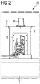
- FIG. 2 is a side view of an antenna assembly 10 illustrated according to an embodiment of the invention.
- the antenna assembly 10 includes an electrician 1 mounted on a car roof 2 of a rail vehicle.
- the electrifier 1 comprises laterally an interface 6 for electrical lines 7, in particular control lines for roof devices and lines of the car wiring.
- a Antennenabstrahlblech 5 is fixedly mounted and on the Antennenabstrahlblech 5 an antenna 4 is arranged.
- FIG. 3 an exploded view of an antenna assembly 10 is illustrated according to an embodiment of the invention.
- an antenna 4 with four screws 4c on a Antennenabstrahlblech 5 is fixed.
- the antenna radiant panel 5 is in turn fastened with a plurality of screws 5a on the upper side 9b of the electric 1.
- a seal 9a Between the Antennenabstrahlblech 5 and the top 9b of the electric 1 is a seal 9a, with the aid of a final ring of water in the electrons 1 can be avoided.
- the antenna line 8 thus extends vertically from the interior of the rail vehicle 3 up through the interior of the electric 1 and through the Antennenabstrahlblech 5 up to the antenna 4.
- the bottom 9c of the electric 1 is by means of screws 12 on a pedestal-like car body 11th fastened, wherein between the car body 11 and the bottom 9c of the electric 1, a further seal 9d is arranged.
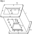
- FIG. 4 a housing of an electrician 1 is illustrated.
- the housing has a collar-like upper side 9b and a collar-like underside 9c extending parallel thereto.
- Part of the housing of the electrical 1 is also a recess 13, which the interface 6 for lines 7 (see FIG. 2 ), in particular control cables for rooftop equipment and wiring of the car wiring, receives.
Landscapes
- Engineering & Computer Science (AREA)
- Remote Sensing (AREA)
- Life Sciences & Earth Sciences (AREA)
- Wood Science & Technology (AREA)
- Mechanical Engineering (AREA)
- Support Of Aerials (AREA)
- Fittings On The Vehicle Exterior For Carrying Loads, And Devices For Holding Or Mounting Articles (AREA)
- Details Of Aerials (AREA)
Abstract
Description
- Die Erfindung betrifft eine Antennenanordnung für ein Dachmodul eines Schienenfahrzeugs. Weiterhin betrifft die Erfindung ein Schienenfahrzeug.
- Elektrifizierte Schienenfahrzeuge umfassen so genannte Kopfmodule oder Dachmodule, welche elektrische Leitungen aufweisen, die zur Versorgung von verschiedenen Arten von Aggregaten mit elektrischer Energie und zur Durchleitung der elektrischen Energie in das Fahrzeuginnere genutzt werden. Herkömmlich werden die wagenseitigen Leitungen durch Durchbrüche in der Fahrerraumrückwand in das Kopfmodul verlegt. Diese Durchbrüche werden durch zusätzliche Brandschutzformteile oder andere Brandschutzmaterialien abgedichtet. Im Kopfmodul werden diese Leitungen an Haltern zu den E-Schnittstellen auf den E-Schränken oder anderen Stellen verlegt. Eine verbesserte Möglichkeit zur Leitungsverlegung ist durch den Einsatz von Elektranten gegeben, die als Schnittstellen für die elektrischen Leitungen zwischen dem Innenraum und der Dachseite dienen. Die wagenseitigen Leitungen enden auf der Innenseite in Steckern, die dort fest montiert sind. Umgekehrt können auch die dachseitigen Kabel an Steckern der Elektranten angeschlossen werden. Diese modulare Bauweise hat den Vorteil, dass das Dachmodul getrennt von dem Innenbereich und der Innenverkabelung fertiggestellt werden kann.
- Dachantennen zur Datenübertragung zwischen einem Schienenfahrzeug und der Landseite müssen so auf dem Schienenfahrzeug montiert werden, dass die Abstrahlung und der Empfang von Radiowellen nicht durch Hindernisse beeinträchtigt wird. Daher müssen die Antennen oberhalb der Dachgeräte innerhalb der Einschränkung montiert werden. Außerdem muss die notwendige elektrische Schnittstelle wasserdicht ausgeführt werden.
- Bisher werden die Antennen auf separaten Haltern oder auf Geräten wie zum Beispiel einem HVAC-System (HVAC = Heating, Ventilation and Air Conditioning = Klimaanlage), befestigt. Die Leitungszuführung muss dabei durch Dachdurchbrüche in Schutzschläuchen über das Dach zu den Antennen erfolgen. In der Regel werden die Antennen auf einen Antennenkasten oder eine Metallplatte montiert. In beiden Fällen wird der Schutzschlauch mit Hilfe einer Verschraubung dicht mit der Antenne verbunden. Es werden also zusätzliche Bauteile, wie zum Beispiel Halter, Montagebleche, Antennenkästen und Schutzschläuche, benötigt, um die Antennen zu installieren.
- Es besteht mithin die Aufgabe, eine Anordnung der Antennen zu wählen, welche eine einfachere Montage zulässt und die Anzahl zusätzlicher Bauteile für die Montage reduziert.
- Diese Aufgabe wird durch eine Antennenanordnung gemäß Patentanspruch 1 und ein Schienenfahrzeug gemäß Patentanspruch 4 gelöst.
- Die erfindungsgemäße Antennenanordnung weist einen Elektranten, welcher auf einem Dach eines Schienenfahrzeugs angeordnet ist, auf. Zudem umfasst die erfindungsgemäße Antennenanordnung eine Antenne, welche an dem Elektranten angeordnet ist und mit diesem fest verbunden ist. Die Antenne dient dazu, eine drahtlose Kommunikation zwischen dem Schienenfahrzeug und stationären Datenübertragungssystemen, wie zum Beispiel dem Internet oder Funktelefonnetzen, zu realisieren. Dabei ist eine elektrische Verbindung zwischen der Antenne und einem Innenraum des Schienenfahrzeugs über den Elektranten hergestellt. Vorteilhaft ist durch die erfindungsgemäße Antennenanordnung der Montageaufwand der Antennen reduziert und die Leitungen, welche zur Antenne führen, können kürzer ausfallen. Weiterhin wird Platz auf dem Dach des Schienenfahrzeugs eingespart und benachbarte Einheiten sich leichter demontierbar.
- Das erfindungsgemäße Schienenfahrzeug weist eine erfindungsgemäße Antennenanordnung auf. Das erfindungsgemäße Schienenfahrzeug teilt die Vorteile der erfindungsgemäßen Antennenanordnung
- Die abhängigen Ansprüche sowie die nachfolgende Beschreibung enthalten jeweils besonders vorteilhafte Ausgestaltungen und Weiterbildungen der Erfindung. Weiterhin können im Rahmen der Erfindung auch die verschiedenen Merkmale unterschiedlicher Ausführungsbeispiele und Ansprüche auch zu neuen Ausführungsbeispielen kombiniert werden.
- In einer Ausgestaltung der erfindungsgemäßen Antennenanordnung weist der Elektrant eine Oberseite auf und die Antenne ist auf der Oberseite des Elektranten angeordnet. Vorteilhaft ist die Antenne derart angeordnet, dass keinerlei oder zumindest weniger Hindernisse im Abstrahlbereich und im Empfangsbereich liegen, wodurch ein optimaler Empfang und eine optimale Emission von Signalen erreicht werden kann.
- In einer Variante der erfindungsgemäßen Antennenanordnung ist zwischen der Antenne und dem Elektranten ein Antennenabstrahlblech angeordnet. Mit Hilfe des Antennenabstrahlblechs wird die Abstrahlung der Antenne auf eine Hemisphäre beschränkt, deren Basiskreis parallel zu der Oberseite des Elektranten liegt. In diesem Bereich wird die Abstrahlung verstärkt, während die darunter liegenden Bereiche, beispielsweise der Fahrgastbereich gegen elektromagnetische Strahlung geschützt wird.
- Die Erfindung wird im Folgenden unter Hinweis auf die beigefügten Figuren anhand von Ausführungsbeispielen noch einmal näher erläutert. Es zeigen:
-
FIG 1 eine schematische Darstellung eines Schienenfahrzeugs mit einer Mehrzahl von Elektranten, welche Teil einer Antennenanordnung gemäß einem Ausführungsbeispiel der Erfindung sind, -
FIG 2 eine Seitenansicht einer Antennenanordnung gemäß einem Ausführungsbeispiel der Erfindung, -
FIG 3 eine Explosionsansicht einer Antennenanordnung gemäß einem Ausführungsbeispiel der Erfindung, -
FIG 4 ein Gehäuse eines Elektranten für eine Antennenanordnung gemäß einem Ausführungsbeispiel der Erfindung. - In
FIG 1 ist eine perspektivische Ansicht auf ein Schienenfahrzeug 3 von schräg oben gezeigt. Das Schienenfahrzeug 3 weist auf seinem Dach 2 eine Vielzahl von technischen Installationen, wie zum Beispiel Klimaanlagen, auf. Weiterhin sind auf dem Dach 2 zwei Antennen 4a, 4b, welche Teil einer Antennenanordnung gemäß einem Ausführungsbeispiel der Erfindung sind, angeordnet. Die Antennen 4a, 4b sind auf Elektranten 1 montiert. Ein solcher Elektrant 1 ist weiter rechts von den beiden Antennen 4a, 4b gezeigt. - In
FIG 2 ist eine Seitenansicht einer Antennenanordnung 10 gemäß einem Ausführungsbeispiel der Erfindung veranschaulicht. Die Antennenanordnung 10 umfasst einen Elektranten 1, der auf einem Wagendach 2 eines Schienenfahrzeugs montiert ist. Der Elektrant 1 umfasst seitlich eine Schnittstelle 6 für elektrische Leitungen 7, insbesondere Steuerleitungen für Dachgeräte und Leitungen der Wagenverdrahtung. Auf der Oberseite des Elektranten 1 ist ein Antennenabstrahlblech 5 fest montiert und auf dem Antennenabstrahlblech 5 ist eine Antenne 4 angeordnet. - In
FIG 3 ist eine Explosionszeichnung einer Antennenanordnung 10 gemäß einem Ausführungsbeispiel der Erfindung veranschaulicht. Wie inFIG 3 zu erkennen ist, ist eine Antenne 4 mit vier Schrauben 4c auf einem Antennenabstrahlblech 5 befestigt. Das Antennenabstrahlblech 5 ist seinerseits mit einer Mehrzahl von Schrauben 5a auf der Oberseite 9b des Elektranten 1 befestigt. Zwischen dem Antennenabstrahlblech 5 und der Oberseite 9b des Elektranten 1 befindet sich eine Dichtung 9a, mit deren Hilfe ein Endringen von Wasser in den Elektranten 1 vermieden werden kann. Durch den Elektranten 1 verläuft vertikal eine Antennenleitung 8, die das Innere eines Schienenfahrzeugs 3 mit der Antenne 4 verbindet. Die Antennenleitung 8 verläuft also vertikal aus dem Innenraum des Schienenfahrzeugs 3 nach oben durch den Innenbereich des Elektranten 1 hindurch und durch das Antennenabstrahlblech 5 nach oben zu der Antenne 4. Die Unterseite 9c des Elektranten 1 ist mit Hilfe von Schrauben 12 auf einem sockelartigen Wagenkasten 11 befestigt, wobei zwischen dem Wagenkasten 11 und der Unterseite 9c des Elektranten 1 eine weitere Dichtung 9d angeordnet ist. - In
FIG 4 ist ein Gehäuse eines Elektranten 1 veranschaulicht. Das Gehäuse weist eine kragenartige Oberseite 9b und eine parallel dazu verlaufende kragenartige Unterseite 9c auf. Teil des Gehäuses des Elektranten 1 ist auch eine Aussparung 13, welche die Schnittstelle 6 für Leitungen 7 (sieheFIG 2 ), insbesondere Steuerleitungen für Dachgeräte und Leitungen der Wagenverdrahtung, aufnimmt. - Es wird abschließend noch einmal darauf hingewiesen, dass es sich bei der beschriebenen Antennenanordnung 10 lediglich um ein bevorzugtes Ausführungsbeispiel der Erfindung handelt und dass die Erfindung vom Fachmann variiert werden kann, ohne den Bereich der Erfindung zu verlassen, soweit er durch die Ansprüche vorgegeben ist. Es wird der Vollständigkeit halber auch darauf hingewiesen, dass die Verwendung der unbestimmten Artikel "ein" bzw. "eine" nicht ausschließt, dass die betreffenden Merkmale auch mehrfach vorhanden sein können.
Claims (4)
- Antennenanordnung (10), aufweisend:- einen Elektranten (1), welcher auf einem Dach (2) eines Schienenfahrzeugs (3) angeordnet ist,- eine Antenne (4), welche an dem Elektranten (1) angeordnet ist und mit diesem fest verbunden ist,wobei eine elektrische Verbindung (8) zwischen der Antenne (4) und einem Innenraum des Schienenfahrzeugs (3) über den Elektranten (1) hergestellt ist.
- Antennenanordnung (10) nach Anspruch 1,
wobei der Elektrant (1) eine Oberseite (9b) aufweist und die Antenne (4) auf der Oberseite (9b) des Elektranten (1) angeordnet ist. - Antennenanordnung (10) nach Anspruch 1 oder 2, wobei zwischen der Antenne (4) und dem Elektranten (1) ein Antennenabstrahlblech (5) angeordnet ist.
- Schienenfahrzeug (3), aufweisend eine Antennenanordnung (10) nach einem der vorstehenden Ansprüche.
Applications Claiming Priority (1)
| Application Number | Priority Date | Filing Date | Title |
|---|---|---|---|
| DE102017217426.9A DE102017217426B3 (de) | 2017-09-29 | 2017-09-29 | Elektranten als Antennenträger |
Publications (2)
| Publication Number | Publication Date |
|---|---|
| EP3462538A1 true EP3462538A1 (de) | 2019-04-03 |
| EP3462538B1 EP3462538B1 (de) | 2021-01-20 |
Family
ID=63490283
Family Applications (1)
| Application Number | Title | Priority Date | Filing Date |
|---|---|---|---|
| EP18192170.1A Active EP3462538B1 (de) | 2017-09-29 | 2018-09-03 | Elektranten als antennenträger |
Country Status (4)
| Country | Link |
|---|---|
| EP (1) | EP3462538B1 (de) |
| CN (1) | CN109599654B (de) |
| DE (1) | DE102017217426B3 (de) |
| RU (1) | RU2690093C1 (de) |
Citations (4)
| Publication number | Priority date | Publication date | Assignee | Title |
|---|---|---|---|---|
| JPH04130801A (ja) * | 1990-09-21 | 1992-05-01 | Sony Corp | 車両用受信アンテナ装置 |
| DE112010002603T5 (de) * | 2009-06-11 | 2014-08-07 | Electro-Motive Diesel Inc. | Modulare Antennenanordung für Lokomotiven |
| US9072771B1 (en) * | 2011-08-26 | 2015-07-07 | Sti-Co Industries, Inc. | Locomotive antenna arrays |
| DE102015203666A1 (de) * | 2015-03-02 | 2016-09-08 | Siemens Aktiengesellschaft | Fahrzeug mit Brandschutzeinrichtung |
Family Cites Families (15)
| Publication number | Priority date | Publication date | Assignee | Title |
|---|---|---|---|---|
| US6710749B2 (en) * | 2000-03-15 | 2004-03-23 | King Controls | Satellite locator system |
| JP2005043102A (ja) * | 2003-07-23 | 2005-02-17 | Murata Mfg Co Ltd | 車載用レーダ装置 |
| JP4064978B2 (ja) * | 2004-05-28 | 2008-03-19 | 株式会社デンソー | 車載アンテナの搭載構造 |
| JP2006013958A (ja) * | 2004-06-25 | 2006-01-12 | Alps Electric Co Ltd | 車載用アンテナ装置 |
| US7839348B2 (en) * | 2008-06-03 | 2010-11-23 | Gary Baker | Automatic satellite tracking system |
| CN201748561U (zh) * | 2010-08-18 | 2011-02-16 | 丰生微电机(上海)有限公司 | 基站智能节能换热机 |
| CN202885977U (zh) * | 2012-09-25 | 2013-04-17 | 广州科易光电技术有限公司 | 一种车载弓网检测系统的防尘机箱 |
| EP3011636B1 (de) * | 2013-06-21 | 2018-10-24 | Laird Technologies, Inc. | Mehrbandige mimo-fahrzeugantennenanordnungen |
| CN203739912U (zh) * | 2014-03-26 | 2014-07-30 | 广州科易光电技术有限公司 | 一种列车弓网在线巡检系统 |
| CN111048889B (zh) * | 2014-07-17 | 2025-02-11 | 胡贝尔和茹纳股份公司 | 天线装置 |
| CN204030365U (zh) * | 2014-08-29 | 2014-12-17 | 国网河南鄢陵县供电公司 | 降温防尘型配电箱 |
| CN104733830B (zh) * | 2015-03-12 | 2017-09-05 | 中车青岛四方机车车辆股份有限公司 | 一种轨道车辆及其车顶天线安装座 |
| CN205060759U (zh) * | 2015-09-30 | 2016-03-02 | 上海佩含保健食品有限公司 | 一种适用于中药生产线的冷链运输装置 |
| CN205768912U (zh) * | 2016-06-29 | 2016-12-07 | 台州中科通信技术有限公司 | 一种移动应急通信指挥车的车顶结构 |
| CN206161163U (zh) * | 2016-08-31 | 2017-05-10 | 广州科易光电技术有限公司 | 高速铁路车载接触网校验红外温度装置 |
-
2017
- 2017-09-29 DE DE102017217426.9A patent/DE102017217426B3/de active Active
-
2018
- 2018-09-03 EP EP18192170.1A patent/EP3462538B1/de active Active
- 2018-09-26 RU RU2018133948A patent/RU2690093C1/ru active
- 2018-09-27 CN CN201811129576.2A patent/CN109599654B/zh active Active
Patent Citations (4)
| Publication number | Priority date | Publication date | Assignee | Title |
|---|---|---|---|---|
| JPH04130801A (ja) * | 1990-09-21 | 1992-05-01 | Sony Corp | 車両用受信アンテナ装置 |
| DE112010002603T5 (de) * | 2009-06-11 | 2014-08-07 | Electro-Motive Diesel Inc. | Modulare Antennenanordung für Lokomotiven |
| US9072771B1 (en) * | 2011-08-26 | 2015-07-07 | Sti-Co Industries, Inc. | Locomotive antenna arrays |
| DE102015203666A1 (de) * | 2015-03-02 | 2016-09-08 | Siemens Aktiengesellschaft | Fahrzeug mit Brandschutzeinrichtung |
Also Published As
| Publication number | Publication date |
|---|---|
| RU2690093C1 (ru) | 2019-05-30 |
| CN109599654B (zh) | 2021-09-03 |
| CN109599654A (zh) | 2019-04-09 |
| EP3462538B1 (de) | 2021-01-20 |
| DE102017217426B3 (de) | 2018-10-31 |
Similar Documents
| Publication | Publication Date | Title |
|---|---|---|
| DE102018205914B4 (de) | Elektrischer Anschlusskasten und Kabelbaum | |
| DE10354284A1 (de) | Abgeschirmter Kabelbaum | |
| DE112015005781T5 (de) | Kraftfahrzeug-Stromversorgungsvorrichtung | |
| DE102006025176A1 (de) | Antennenmodul für ein Fahrzeug | |
| DE102015217243A1 (de) | Antennenmodul | |
| DE212011100212U1 (de) | Rahmen für einen modularen spannungsgeführten Wandler und lsolationsvorrichtung | |
| DE202015009331U1 (de) | Antennenanordnung und Stecker für eine Antennenanordnung | |
| DE102007050421A1 (de) | Mit Kabel ausgestatteter Verbinder | |
| DE102020210012A1 (de) | Haifischflossenantenne für Fahrzeug | |
| DE112007000951B4 (de) | Aufnahmegehäuse | |
| DE102006049604C5 (de) | Hochstromkabel für Fahrzeuge sowie Kabelkanal zum elektrisch isolierenden Aufnehmen eines solchen Hochstromkabels | |
| DE202014010470U1 (de) | Schienenfahrzeugwagen | |
| DE102017217426B3 (de) | Elektranten als Antennenträger | |
| EP2794381B1 (de) | Schaltvorrichtung für ein elektrisch angetriebenes fahrzeug und elektrofahrzeug | |
| DE102016201431A1 (de) | Außenelement und Kabelbaum | |
| EP1447878A1 (de) | Antenne für eine Funkzentralverriegelung | |
| EP3799238A1 (de) | Stromschienensystem | |
| DE1616794B1 (de) | Anlagengestell fuer Geraete der Hoechstfrequenztechnik,insbesondere der Richtfunktechnik | |
| EP0955206A2 (de) | Montagewand | |
| DE102016217165B4 (de) | Ausgestaltung einer Verlegung eines Kabelbaums | |
| DE102020124963B4 (de) | Fahrzeugschaltungselement | |
| DE102016111221B4 (de) | Strom- und/oder Datenschienenanordnung mit abgedichteten Abgangsknoten für ein Kraftfahrzeug | |
| DE102017100245A1 (de) | Reihenbausteinanordnung mit einem Energiebussystem | |
| EP1173910B1 (de) | Befestigungsadapter für befehls- bzw. meldegeräte | |
| DE102016216696A1 (de) | Kabelbaum |
Legal Events
| Date | Code | Title | Description |
|---|---|---|---|
| PUAI | Public reference made under article 153(3) epc to a published international application that has entered the european phase |
Free format text: ORIGINAL CODE: 0009012 |
|
| STAA | Information on the status of an ep patent application or granted ep patent |
Free format text: STATUS: THE APPLICATION HAS BEEN PUBLISHED |
|
| AK | Designated contracting states |
Kind code of ref document: A1 Designated state(s): AL AT BE BG CH CY CZ DE DK EE ES FI FR GB GR HR HU IE IS IT LI LT LU LV MC MK MT NL NO PL PT RO RS SE SI SK SM TR |
|
| AX | Request for extension of the european patent |
Extension state: BA ME |
|
| STAA | Information on the status of an ep patent application or granted ep patent |
Free format text: STATUS: REQUEST FOR EXAMINATION WAS MADE |
|
| STAA | Information on the status of an ep patent application or granted ep patent |
Free format text: STATUS: EXAMINATION IS IN PROGRESS |
|
| 17P | Request for examination filed |
Effective date: 20191004 |
|
| RBV | Designated contracting states (corrected) |
Designated state(s): AL AT BE BG CH CY CZ DE DK EE ES FI FR GB GR HR HU IE IS IT LI LT LU LV MC MK MT NL NO PL PT RO RS SE SI SK SM TR |
|
| 17Q | First examination report despatched |
Effective date: 20191031 |
|
| GRAP | Despatch of communication of intention to grant a patent |
Free format text: ORIGINAL CODE: EPIDOSNIGR1 |
|
| STAA | Information on the status of an ep patent application or granted ep patent |
Free format text: STATUS: GRANT OF PATENT IS INTENDED |
|
| RIC1 | Information provided on ipc code assigned before grant |
Ipc: B61D 17/12 20060101ALI20200828BHEP Ipc: H02G 3/08 20060101ALN20200828BHEP Ipc: H01Q 1/32 20060101AFI20200828BHEP |
|
| INTG | Intention to grant announced |
Effective date: 20200916 |
|
| GRAS | Grant fee paid |
Free format text: ORIGINAL CODE: EPIDOSNIGR3 |
|
| GRAA | (expected) grant |
Free format text: ORIGINAL CODE: 0009210 |
|
| STAA | Information on the status of an ep patent application or granted ep patent |
Free format text: STATUS: THE PATENT HAS BEEN GRANTED |
|
| AK | Designated contracting states |
Kind code of ref document: B1 Designated state(s): AL AT BE BG CH CY CZ DE DK EE ES FI FR GB GR HR HU IE IS IT LI LT LU LV MC MK MT NL NO PL PT RO RS SE SI SK SM TR |
|
| REG | Reference to a national code |
Ref country code: GB Ref legal event code: FG4D Free format text: NOT ENGLISH |
|
| REG | Reference to a national code |
Ref country code: CH Ref legal event code: EP |
|
| REG | Reference to a national code |
Ref country code: DE Ref legal event code: R096 Ref document number: 502018003706 Country of ref document: DE |
|
| REG | Reference to a national code |
Ref country code: AT Ref legal event code: REF Ref document number: 1357165 Country of ref document: AT Kind code of ref document: T Effective date: 20210215 Ref country code: CH Ref legal event code: NV Representative=s name: SIEMENS SCHWEIZ AG, CH |
|
| REG | Reference to a national code |
Ref country code: IE Ref legal event code: FG4D Free format text: LANGUAGE OF EP DOCUMENT: GERMAN |
|
| REG | Reference to a national code |
Ref country code: NL Ref legal event code: MP Effective date: 20210120 |
|
| REG | Reference to a national code |
Ref country code: LT Ref legal event code: MG9D |
|
| PG25 | Lapsed in a contracting state [announced via postgrant information from national office to epo] |
Ref country code: HR Free format text: LAPSE BECAUSE OF FAILURE TO SUBMIT A TRANSLATION OF THE DESCRIPTION OR TO PAY THE FEE WITHIN THE PRESCRIBED TIME-LIMIT Effective date: 20210120 Ref country code: FI Free format text: LAPSE BECAUSE OF FAILURE TO SUBMIT A TRANSLATION OF THE DESCRIPTION OR TO PAY THE FEE WITHIN THE PRESCRIBED TIME-LIMIT Effective date: 20210120 Ref country code: GR Free format text: LAPSE BECAUSE OF FAILURE TO SUBMIT A TRANSLATION OF THE DESCRIPTION OR TO PAY THE FEE WITHIN THE PRESCRIBED TIME-LIMIT Effective date: 20210421 Ref country code: BG Free format text: LAPSE BECAUSE OF FAILURE TO SUBMIT A TRANSLATION OF THE DESCRIPTION OR TO PAY THE FEE WITHIN THE PRESCRIBED TIME-LIMIT Effective date: 20210420 Ref country code: LT Free format text: LAPSE BECAUSE OF FAILURE TO SUBMIT A TRANSLATION OF THE DESCRIPTION OR TO PAY THE FEE WITHIN THE PRESCRIBED TIME-LIMIT Effective date: 20210120 Ref country code: NO Free format text: LAPSE BECAUSE OF FAILURE TO SUBMIT A TRANSLATION OF THE DESCRIPTION OR TO PAY THE FEE WITHIN THE PRESCRIBED TIME-LIMIT Effective date: 20210420 Ref country code: PT Free format text: LAPSE BECAUSE OF FAILURE TO SUBMIT A TRANSLATION OF THE DESCRIPTION OR TO PAY THE FEE WITHIN THE PRESCRIBED TIME-LIMIT Effective date: 20210520 |
|
| PG25 | Lapsed in a contracting state [announced via postgrant information from national office to epo] |
Ref country code: LV Free format text: LAPSE BECAUSE OF FAILURE TO SUBMIT A TRANSLATION OF THE DESCRIPTION OR TO PAY THE FEE WITHIN THE PRESCRIBED TIME-LIMIT Effective date: 20210120 Ref country code: RS Free format text: LAPSE BECAUSE OF FAILURE TO SUBMIT A TRANSLATION OF THE DESCRIPTION OR TO PAY THE FEE WITHIN THE PRESCRIBED TIME-LIMIT Effective date: 20210120 Ref country code: PL Free format text: LAPSE BECAUSE OF FAILURE TO SUBMIT A TRANSLATION OF THE DESCRIPTION OR TO PAY THE FEE WITHIN THE PRESCRIBED TIME-LIMIT Effective date: 20210120 Ref country code: SE Free format text: LAPSE BECAUSE OF FAILURE TO SUBMIT A TRANSLATION OF THE DESCRIPTION OR TO PAY THE FEE WITHIN THE PRESCRIBED TIME-LIMIT Effective date: 20210120 |
|
| PG25 | Lapsed in a contracting state [announced via postgrant information from national office to epo] |
Ref country code: IS Free format text: LAPSE BECAUSE OF FAILURE TO SUBMIT A TRANSLATION OF THE DESCRIPTION OR TO PAY THE FEE WITHIN THE PRESCRIBED TIME-LIMIT Effective date: 20210520 |
|
| REG | Reference to a national code |
Ref country code: DE Ref legal event code: R097 Ref document number: 502018003706 Country of ref document: DE |
|
| PG25 | Lapsed in a contracting state [announced via postgrant information from national office to epo] |
Ref country code: CZ Free format text: LAPSE BECAUSE OF FAILURE TO SUBMIT A TRANSLATION OF THE DESCRIPTION OR TO PAY THE FEE WITHIN THE PRESCRIBED TIME-LIMIT Effective date: 20210120 Ref country code: EE Free format text: LAPSE BECAUSE OF FAILURE TO SUBMIT A TRANSLATION OF THE DESCRIPTION OR TO PAY THE FEE WITHIN THE PRESCRIBED TIME-LIMIT Effective date: 20210120 Ref country code: SM Free format text: LAPSE BECAUSE OF FAILURE TO SUBMIT A TRANSLATION OF THE DESCRIPTION OR TO PAY THE FEE WITHIN THE PRESCRIBED TIME-LIMIT Effective date: 20210120 |
|
| PLBE | No opposition filed within time limit |
Free format text: ORIGINAL CODE: 0009261 |
|
| STAA | Information on the status of an ep patent application or granted ep patent |
Free format text: STATUS: NO OPPOSITION FILED WITHIN TIME LIMIT |
|
| PG25 | Lapsed in a contracting state [announced via postgrant information from national office to epo] |
Ref country code: DK Free format text: LAPSE BECAUSE OF FAILURE TO SUBMIT A TRANSLATION OF THE DESCRIPTION OR TO PAY THE FEE WITHIN THE PRESCRIBED TIME-LIMIT Effective date: 20210120 Ref country code: RO Free format text: LAPSE BECAUSE OF FAILURE TO SUBMIT A TRANSLATION OF THE DESCRIPTION OR TO PAY THE FEE WITHIN THE PRESCRIBED TIME-LIMIT Effective date: 20210120 Ref country code: SK Free format text: LAPSE BECAUSE OF FAILURE TO SUBMIT A TRANSLATION OF THE DESCRIPTION OR TO PAY THE FEE WITHIN THE PRESCRIBED TIME-LIMIT Effective date: 20210120 |
|
| 26N | No opposition filed |
Effective date: 20211021 |
|
| PG25 | Lapsed in a contracting state [announced via postgrant information from national office to epo] |
Ref country code: AL Free format text: LAPSE BECAUSE OF FAILURE TO SUBMIT A TRANSLATION OF THE DESCRIPTION OR TO PAY THE FEE WITHIN THE PRESCRIBED TIME-LIMIT Effective date: 20210120 Ref country code: ES Free format text: LAPSE BECAUSE OF FAILURE TO SUBMIT A TRANSLATION OF THE DESCRIPTION OR TO PAY THE FEE WITHIN THE PRESCRIBED TIME-LIMIT Effective date: 20210120 |
|
| PG25 | Lapsed in a contracting state [announced via postgrant information from national office to epo] |
Ref country code: SI Free format text: LAPSE BECAUSE OF FAILURE TO SUBMIT A TRANSLATION OF THE DESCRIPTION OR TO PAY THE FEE WITHIN THE PRESCRIBED TIME-LIMIT Effective date: 20210120 |
|
| PG25 | Lapsed in a contracting state [announced via postgrant information from national office to epo] |
Ref country code: IT Free format text: LAPSE BECAUSE OF FAILURE TO SUBMIT A TRANSLATION OF THE DESCRIPTION OR TO PAY THE FEE WITHIN THE PRESCRIBED TIME-LIMIT Effective date: 20210120 |
|
| REG | Reference to a national code |
Ref country code: BE Ref legal event code: MM Effective date: 20210930 |
|
| PG25 | Lapsed in a contracting state [announced via postgrant information from national office to epo] |
Ref country code: IS Free format text: LAPSE BECAUSE OF FAILURE TO SUBMIT A TRANSLATION OF THE DESCRIPTION OR TO PAY THE FEE WITHIN THE PRESCRIBED TIME-LIMIT Effective date: 20210520 Ref country code: MC Free format text: LAPSE BECAUSE OF FAILURE TO SUBMIT A TRANSLATION OF THE DESCRIPTION OR TO PAY THE FEE WITHIN THE PRESCRIBED TIME-LIMIT Effective date: 20210120 |
|
| PG25 | Lapsed in a contracting state [announced via postgrant information from national office to epo] |
Ref country code: LU Free format text: LAPSE BECAUSE OF NON-PAYMENT OF DUE FEES Effective date: 20210903 Ref country code: IE Free format text: LAPSE BECAUSE OF NON-PAYMENT OF DUE FEES Effective date: 20210903 Ref country code: BE Free format text: LAPSE BECAUSE OF NON-PAYMENT OF DUE FEES Effective date: 20210930 |
|
| PG25 | Lapsed in a contracting state [announced via postgrant information from national office to epo] |
Ref country code: NL Free format text: LAPSE BECAUSE OF NON-PAYMENT OF DUE FEES Effective date: 20210120 Ref country code: CY Free format text: LAPSE BECAUSE OF FAILURE TO SUBMIT A TRANSLATION OF THE DESCRIPTION OR TO PAY THE FEE WITHIN THE PRESCRIBED TIME-LIMIT Effective date: 20210120 |
|
| PG25 | Lapsed in a contracting state [announced via postgrant information from national office to epo] |
Ref country code: HU Free format text: LAPSE BECAUSE OF FAILURE TO SUBMIT A TRANSLATION OF THE DESCRIPTION OR TO PAY THE FEE WITHIN THE PRESCRIBED TIME-LIMIT; INVALID AB INITIO Effective date: 20180903 |
|
| PG25 | Lapsed in a contracting state [announced via postgrant information from national office to epo] |
Ref country code: MK Free format text: LAPSE BECAUSE OF FAILURE TO SUBMIT A TRANSLATION OF THE DESCRIPTION OR TO PAY THE FEE WITHIN THE PRESCRIBED TIME-LIMIT Effective date: 20210120 |
|
| PG25 | Lapsed in a contracting state [announced via postgrant information from national office to epo] |
Ref country code: TR Free format text: LAPSE BECAUSE OF FAILURE TO SUBMIT A TRANSLATION OF THE DESCRIPTION OR TO PAY THE FEE WITHIN THE PRESCRIBED TIME-LIMIT Effective date: 20210120 |
|
| PG25 | Lapsed in a contracting state [announced via postgrant information from national office to epo] |
Ref country code: MT Free format text: LAPSE BECAUSE OF FAILURE TO SUBMIT A TRANSLATION OF THE DESCRIPTION OR TO PAY THE FEE WITHIN THE PRESCRIBED TIME-LIMIT Effective date: 20210120 |
|
| REG | Reference to a national code |
Ref country code: DE Ref legal event code: R081 Ref document number: 502018003706 Country of ref document: DE Owner name: SIEMENS MOBILITY GMBH, DE Free format text: FORMER OWNER: SIEMENS MOBILITY GMBH, 81739 MUENCHEN, DE |
|
| PGFP | Annual fee paid to national office [announced via postgrant information from national office to epo] |
Ref country code: FR Payment date: 20250915 Year of fee payment: 8 Ref country code: AT Payment date: 20250818 Year of fee payment: 8 |
|
| REG | Reference to a national code |
Ref country code: CH Ref legal event code: U11 Free format text: ST27 STATUS EVENT CODE: U-0-0-U10-U11 (AS PROVIDED BY THE NATIONAL OFFICE) Effective date: 20251210 |
|
| PGFP | Annual fee paid to national office [announced via postgrant information from national office to epo] |
Ref country code: DE Payment date: 20251120 Year of fee payment: 8 |
|
| PGFP | Annual fee paid to national office [announced via postgrant information from national office to epo] |
Ref country code: GB Payment date: 20251002 Year of fee payment: 8 |
|
| PGFP | Annual fee paid to national office [announced via postgrant information from national office to epo] |
Ref country code: CH Payment date: 20251210 Year of fee payment: 8 |