EP3456970B1 - Kunstharzlager und spiralverdichter damit - Google Patents
Kunstharzlager und spiralverdichter damit Download PDFInfo
- Publication number
- EP3456970B1 EP3456970B1 EP18198600.1A EP18198600A EP3456970B1 EP 3456970 B1 EP3456970 B1 EP 3456970B1 EP 18198600 A EP18198600 A EP 18198600A EP 3456970 B1 EP3456970 B1 EP 3456970B1
- Authority
- EP
- European Patent Office
- Prior art keywords
- bearing
- thickness
- scroll
- journal bearing
- scroll compressor
- Prior art date
- Legal status (The legal status is an assumption and is not a legal conclusion. Google has not performed a legal analysis and makes no representation as to the accuracy of the status listed.)
- Active
Links
Images


Classifications
-
- F—MECHANICAL ENGINEERING; LIGHTING; HEATING; WEAPONS; BLASTING
- F04—POSITIVE - DISPLACEMENT MACHINES FOR LIQUIDS; PUMPS FOR LIQUIDS OR ELASTIC FLUIDS
- F04C—ROTARY-PISTON, OR OSCILLATING-PISTON, POSITIVE-DISPLACEMENT MACHINES FOR LIQUIDS; ROTARY-PISTON, OR OSCILLATING-PISTON, POSITIVE-DISPLACEMENT PUMPS
- F04C29/00—Component parts, details or accessories of pumps or pumping installations, not provided for in groups F04C18/00 - F04C28/00
- F04C29/02—Lubrication; Lubricant separation
-
- F—MECHANICAL ENGINEERING; LIGHTING; HEATING; WEAPONS; BLASTING
- F04—POSITIVE - DISPLACEMENT MACHINES FOR LIQUIDS; PUMPS FOR LIQUIDS OR ELASTIC FLUIDS
- F04C—ROTARY-PISTON, OR OSCILLATING-PISTON, POSITIVE-DISPLACEMENT MACHINES FOR LIQUIDS; ROTARY-PISTON, OR OSCILLATING-PISTON, POSITIVE-DISPLACEMENT PUMPS
- F04C18/00—Rotary-piston pumps specially adapted for elastic fluids
- F04C18/02—Rotary-piston pumps specially adapted for elastic fluids of arcuate-engagement type, i.e. with circular translatory movement of co-operating members, each member having the same number of teeth or tooth-equivalents
-
- F—MECHANICAL ENGINEERING; LIGHTING; HEATING; WEAPONS; BLASTING
- F04—POSITIVE - DISPLACEMENT MACHINES FOR LIQUIDS; PUMPS FOR LIQUIDS OR ELASTIC FLUIDS
- F04C—ROTARY-PISTON, OR OSCILLATING-PISTON, POSITIVE-DISPLACEMENT MACHINES FOR LIQUIDS; ROTARY-PISTON, OR OSCILLATING-PISTON, POSITIVE-DISPLACEMENT PUMPS
- F04C18/00—Rotary-piston pumps specially adapted for elastic fluids
- F04C18/02—Rotary-piston pumps specially adapted for elastic fluids of arcuate-engagement type, i.e. with circular translatory movement of co-operating members, each member having the same number of teeth or tooth-equivalents
- F04C18/0207—Rotary-piston pumps specially adapted for elastic fluids of arcuate-engagement type, i.e. with circular translatory movement of co-operating members, each member having the same number of teeth or tooth-equivalents both members having co-operating elements in spiral form
- F04C18/0215—Rotary-piston pumps specially adapted for elastic fluids of arcuate-engagement type, i.e. with circular translatory movement of co-operating members, each member having the same number of teeth or tooth-equivalents both members having co-operating elements in spiral form where only one member is moving
-
- F—MECHANICAL ENGINEERING; LIGHTING; HEATING; WEAPONS; BLASTING
- F04—POSITIVE - DISPLACEMENT MACHINES FOR LIQUIDS; PUMPS FOR LIQUIDS OR ELASTIC FLUIDS
- F04D—NON-POSITIVE-DISPLACEMENT PUMPS
- F04D29/00—Details, component parts, or accessories
- F04D29/04—Shafts or bearings, or assemblies thereof
-
- F—MECHANICAL ENGINEERING; LIGHTING; HEATING; WEAPONS; BLASTING
- F16—ENGINEERING ELEMENTS AND UNITS; GENERAL MEASURES FOR PRODUCING AND MAINTAINING EFFECTIVE FUNCTIONING OF MACHINES OR INSTALLATIONS; THERMAL INSULATION IN GENERAL
- F16C—SHAFTS; FLEXIBLE SHAFTS; ELEMENTS OR CRANKSHAFT MECHANISMS; ROTARY BODIES OTHER THAN GEARING ELEMENTS; BEARINGS
- F16C33/00—Parts of bearings; Special methods for making bearings or parts thereof
- F16C33/02—Parts of sliding-contact bearings
- F16C33/04—Brasses; Bushes; Linings
- F16C33/20—Sliding surface consisting mainly of plastics
- F16C33/201—Composition of the plastic
-
- F—MECHANICAL ENGINEERING; LIGHTING; HEATING; WEAPONS; BLASTING
- F04—POSITIVE - DISPLACEMENT MACHINES FOR LIQUIDS; PUMPS FOR LIQUIDS OR ELASTIC FLUIDS
- F04C—ROTARY-PISTON, OR OSCILLATING-PISTON, POSITIVE-DISPLACEMENT MACHINES FOR LIQUIDS; ROTARY-PISTON, OR OSCILLATING-PISTON, POSITIVE-DISPLACEMENT PUMPS
- F04C15/00—Component parts, details or accessories of machines, pumps or pumping installations, not provided for in groups F04C2/00 - F04C14/00
- F04C15/0057—Driving elements, brakes, couplings, transmission specially adapted for machines or pumps
- F04C15/0061—Means for transmitting movement from the prime mover to driven parts of the pump, e.g. clutches, couplings, transmissions
- F04C15/0073—Couplings between rotors and input or output shafts acting by interengaging or mating parts, i.e. positive coupling of rotor and shaft
-
- F—MECHANICAL ENGINEERING; LIGHTING; HEATING; WEAPONS; BLASTING
- F04—POSITIVE - DISPLACEMENT MACHINES FOR LIQUIDS; PUMPS FOR LIQUIDS OR ELASTIC FLUIDS
- F04C—ROTARY-PISTON, OR OSCILLATING-PISTON, POSITIVE-DISPLACEMENT MACHINES FOR LIQUIDS; ROTARY-PISTON, OR OSCILLATING-PISTON, POSITIVE-DISPLACEMENT PUMPS
- F04C2210/00—Fluid
- F04C2210/14—Lubricant
-
- F—MECHANICAL ENGINEERING; LIGHTING; HEATING; WEAPONS; BLASTING
- F04—POSITIVE - DISPLACEMENT MACHINES FOR LIQUIDS; PUMPS FOR LIQUIDS OR ELASTIC FLUIDS
- F04C—ROTARY-PISTON, OR OSCILLATING-PISTON, POSITIVE-DISPLACEMENT MACHINES FOR LIQUIDS; ROTARY-PISTON, OR OSCILLATING-PISTON, POSITIVE-DISPLACEMENT PUMPS
- F04C2230/00—Manufacture
- F04C2230/60—Assembly methods
-
- F—MECHANICAL ENGINEERING; LIGHTING; HEATING; WEAPONS; BLASTING
- F04—POSITIVE - DISPLACEMENT MACHINES FOR LIQUIDS; PUMPS FOR LIQUIDS OR ELASTIC FLUIDS
- F04C—ROTARY-PISTON, OR OSCILLATING-PISTON, POSITIVE-DISPLACEMENT MACHINES FOR LIQUIDS; ROTARY-PISTON, OR OSCILLATING-PISTON, POSITIVE-DISPLACEMENT PUMPS
- F04C2240/00—Components
- F04C2240/50—Bearings
-
- F—MECHANICAL ENGINEERING; LIGHTING; HEATING; WEAPONS; BLASTING
- F04—POSITIVE - DISPLACEMENT MACHINES FOR LIQUIDS; PUMPS FOR LIQUIDS OR ELASTIC FLUIDS
- F04C—ROTARY-PISTON, OR OSCILLATING-PISTON, POSITIVE-DISPLACEMENT MACHINES FOR LIQUIDS; ROTARY-PISTON, OR OSCILLATING-PISTON, POSITIVE-DISPLACEMENT PUMPS
- F04C2240/00—Components
- F04C2240/50—Bearings
- F04C2240/54—Hydrostatic or hydrodynamic bearing assemblies specially adapted for rotary positive displacement pumps or compressors
-
- F—MECHANICAL ENGINEERING; LIGHTING; HEATING; WEAPONS; BLASTING
- F04—POSITIVE - DISPLACEMENT MACHINES FOR LIQUIDS; PUMPS FOR LIQUIDS OR ELASTIC FLUIDS
- F04C—ROTARY-PISTON, OR OSCILLATING-PISTON, POSITIVE-DISPLACEMENT MACHINES FOR LIQUIDS; ROTARY-PISTON, OR OSCILLATING-PISTON, POSITIVE-DISPLACEMENT PUMPS
- F04C2240/00—Components
- F04C2240/60—Shafts
- F04C2240/603—Shafts with internal channels for fluid distribution, e.g. hollow shaft
-
- F—MECHANICAL ENGINEERING; LIGHTING; HEATING; WEAPONS; BLASTING
- F04—POSITIVE - DISPLACEMENT MACHINES FOR LIQUIDS; PUMPS FOR LIQUIDS OR ELASTIC FLUIDS
- F04C—ROTARY-PISTON, OR OSCILLATING-PISTON, POSITIVE-DISPLACEMENT MACHINES FOR LIQUIDS; ROTARY-PISTON, OR OSCILLATING-PISTON, POSITIVE-DISPLACEMENT PUMPS
- F04C23/00—Combinations of two or more pumps, each being of rotary-piston or oscillating-piston type, specially adapted for elastic fluids; Pumping installations specially adapted for elastic fluids; Multi-stage pumps specially adapted for elastic fluids
- F04C23/008—Hermetic pumps
-
- F—MECHANICAL ENGINEERING; LIGHTING; HEATING; WEAPONS; BLASTING
- F05—INDEXING SCHEMES RELATING TO ENGINES OR PUMPS IN VARIOUS SUBCLASSES OF CLASSES F01-F04
- F05C—INDEXING SCHEME RELATING TO MATERIALS, MATERIAL PROPERTIES OR MATERIAL CHARACTERISTICS FOR MACHINES, ENGINES OR PUMPS OTHER THAN NON-POSITIVE-DISPLACEMENT MACHINES OR ENGINES
- F05C2225/00—Synthetic polymers, e.g. plastics; Rubber
- F05C2225/12—Polyetheretherketones, e.g. PEEK
-
- F—MECHANICAL ENGINEERING; LIGHTING; HEATING; WEAPONS; BLASTING
- F05—INDEXING SCHEMES RELATING TO ENGINES OR PUMPS IN VARIOUS SUBCLASSES OF CLASSES F01-F04
- F05C—INDEXING SCHEME RELATING TO MATERIALS, MATERIAL PROPERTIES OR MATERIAL CHARACTERISTICS FOR MACHINES, ENGINES OR PUMPS OTHER THAN NON-POSITIVE-DISPLACEMENT MACHINES OR ENGINES
- F05C2251/00—Material properties
- F05C2251/04—Thermal properties
-
- F—MECHANICAL ENGINEERING; LIGHTING; HEATING; WEAPONS; BLASTING
- F16—ENGINEERING ELEMENTS AND UNITS; GENERAL MEASURES FOR PRODUCING AND MAINTAINING EFFECTIVE FUNCTIONING OF MACHINES OR INSTALLATIONS; THERMAL INSULATION IN GENERAL
- F16C—SHAFTS; FLEXIBLE SHAFTS; ELEMENTS OR CRANKSHAFT MECHANISMS; ROTARY BODIES OTHER THAN GEARING ELEMENTS; BEARINGS
- F16C2208/00—Plastics; Synthetic resins, e.g. rubbers
-
- F—MECHANICAL ENGINEERING; LIGHTING; HEATING; WEAPONS; BLASTING
- F16—ENGINEERING ELEMENTS AND UNITS; GENERAL MEASURES FOR PRODUCING AND MAINTAINING EFFECTIVE FUNCTIONING OF MACHINES OR INSTALLATIONS; THERMAL INSULATION IN GENERAL
- F16C—SHAFTS; FLEXIBLE SHAFTS; ELEMENTS OR CRANKSHAFT MECHANISMS; ROTARY BODIES OTHER THAN GEARING ELEMENTS; BEARINGS
- F16C2208/00—Plastics; Synthetic resins, e.g. rubbers
- F16C2208/20—Thermoplastic resins
- F16C2208/36—Polyarylene ether ketones [PAEK], e.g. PEK, PEEK
-
- F—MECHANICAL ENGINEERING; LIGHTING; HEATING; WEAPONS; BLASTING
- F16—ENGINEERING ELEMENTS AND UNITS; GENERAL MEASURES FOR PRODUCING AND MAINTAINING EFFECTIVE FUNCTIONING OF MACHINES OR INSTALLATIONS; THERMAL INSULATION IN GENERAL
- F16C—SHAFTS; FLEXIBLE SHAFTS; ELEMENTS OR CRANKSHAFT MECHANISMS; ROTARY BODIES OTHER THAN GEARING ELEMENTS; BEARINGS
- F16C2360/00—Engines or pumps
- F16C2360/42—Pumps with cylinders or pistons
Definitions
- the present disclosure relates to a synthetic resin bearing and a scroll compressor using the same, and more particularly, to a bearing interposed between a rotational shaft of a scroll compressor and an orbiting scroll to reduce friction loss, and a scroll compressor having the same.
- a scroll compressor is a compressor compressing a refrigerant by changing a volume of a compression chamber formed by a pair of scrolls facing each other.
- a scroll compressor In comparison to a reciprocating compressor or a rotary compressor, a scroll compressor has high efficiency, generates less vibration and noise, and is small and lightweight, and thus, it is commonly used in air-conditioners.
- FIG. 1 is a cross-sectional view schematically illustrating an example of a scroll compressor.
- the scroll compressor includes a main frame fixed within a casing (not shown) therein, and an orbiting scroll 20 is installed above the main frame 10 such that it is rotationally driven.
- a fixed scroll 30 is disposed above the orbiting scroll 20 and a rotational shaft 40 for rotationally driving the orbiting scroll 20 is installed within the main frame 10 and the orbiting scroll 20.
- the rotational shaft 40 passes through a shaft insertion hole 12 formed in the main frame 10 and is fixed in a state in which an end portion thereof is inserted into a boss portion 22 formed on the bottom of the orbiting scroll 20.
- a journal bearing in the form of a bush is inserted into the shaft insertion hole 12 and the boss portion 22.
- a polytetrafluoroethylene (PTFE)-based bearing formed by coating sintered particles or a magnetic lubricating resin for reinforcing a lubricating function on a surface of a support made of a steel material and a white metal-based bearing having lubricating characteristics reinforced by laminating an aluminum alloy on a surface of a support have been used as a journal bearing.
- PTFE polytetrafluoroethylene
- a bronze sintered layer and a functional surface containing Teflon may be formed or a white metal such as aluminum may be laminated to satisfy rigidity (stiffness), abrasion resistance, lubricating performance.
- WO 2012/020740 A1 describes a refrigerant compressor being provided with a compression mechanism part for interlocking a fixed scroll and a pivoting scroll and for compressing refrigerant, and a rotary shaft for driving the compressing mechanism part wherein either the engagement part for the rotary shaft and the compression mechanism part or a rotation support part for supporting the rotary shaft is provided with slide bearings.
- WO 2012/043332 A1 describes a high-precision composite plane bearing which has a synthetic resin bearing layer on a base of sintered metal to provide precision rotational torque with stability and which can be used as plain bearings for receiving a relatively large radial load or axial load, for example for receiving the rotational shafts of a room air conditioner compressor or a car air conditioner compressor.
- an aspect of the detailed description is to provide a synthetic resin bearing capable of reducing a size of a compressor, while providing a sufficient degree of lubricating performance and abrasion resistance.
- Another aspect of the detailed description is to provide a scroll compressor having the foregoing synthetic resin bearing.
- a synthetic resin bearing as a journal bearing is defined in claim 1.
- the thickness t1 is set to be smaller than 2 mm, and t ⁇ 1mm may be satisfied.
- the journal bearing may be press-fit to the orbiting scroll or the main frame so as to be fixed, and the thickness t may be set to be greater than a minimum thickness t2 with which the journal bearing is press-fit without plastic deformation.
- the thickness t of the journal bearing may satisfy 0.17mm ⁇ t ⁇ 1 mm.
- a scroll compressor is defined in claim 7.
- thickness with which a temperature in a contact surface between the rotational shaft and the journal bearing during an operation of the scroll compressor corresponds to a glass transition temperature is t1
- a minimum thickness with which the journal bearing is press-fit to the shaft insertion hole or the boss portion without plastic deformation is t2
- a thickness t of the journal bearing satisfies t2 ⁇ t ⁇ t1.
- the thickness t1 may be 1 mm.
- the thickness t2 may be 0.17 mm.
- the boss portion may be disposed to be coplanar with an orbiting wrap of the orbiting scroll.
- journal bearing is formed of a PEEK material
- abrasion resistance and lubricating performance equal to or more than those of the conventional PTFE-based bearing or white metal-based bearing having a support can be secured, while a thickness of the bearing can be reduced.
- a size of the compressor can be reduced and a degree of freedom of designing can be enhanced.
- journal bearing in determining a minimum thickness of the journal bearing, since the minimum thickness is determined in consideration of a plastic deformation during a press-fitting operation, the journal bearing can be easily and firmly coupled.
- FIG. 2 is an internal cross-sectional view illustrating an example of a scroll compressor employing an example of a synthetic resin bearing according to an embodiment of the present invention.
- the present inventive concept is not necessarily limited to the scroll compressor and, obviously, may be applied to any type of compressor using a bearing to reduce frictional resistance with respect to a rotational shaft.
- a scroll compressor 100 in a scroll compressor 100 according to an embodiment of the present invention, a main frame 120 and a subframe 130 are installed within an airtight container 110, a driving motor 140 as an electric unit is installed between the main frame 120 and the subframe 130, and a compression unit including a fixed scroll 150 and an orbiting scroll 160 are installed above the main frame 120 and coupled to the driving motor 140 to compress a refrigerant.
- the driving motor 140 includes a stator 141 around which a coil is wound, a rotor 142 rotatably inserted into the stator 141, and a rotational shaft 143 press-fit to the center of the rotor 142 to transmit rotatory power to a compression mechanism unit.
- the rotational shaft 143 has a driving pin portion 144 formed to be protruded from an upper end thereof such that it is eccentric with respect to a rotation center thereof.
- the compression mechanism unit includes the fixed scroll 150 fixed to an upper surface of the main frame 120, the orbiting scroll 160 mounted on the upper surface of the main frame 120 such that it is engaged with the fixed scroll 150, and an oldhamring 170 disposed between the orbiting scroll 160 and the main frame 120 to prevent rotation of the orbiting scroll 160.
- the fixed scroll 150 includes a fixed wrap 151 wound in a spiral manner to configure a compression chamber P together with an orbiting wrap 161, and the orbiting scroll 160 includes an orbiting wrap 161 wound in a spiral manner and engaged with a fixed wrap 151 to form the compression chamber P.
- a boss portion 162 is protruded from a lower surface of the orbiting scroll 160, namely, from the opposite side of the orbiting wrap 161, and coupled to the rotational shaft 143 to receive rotator power therefrom.
- a first bearing 163 is coupled to the boss portion 162 of the orbiting scroll 160 such that it slides in a radius direction of the driving pin portion 144 of the rotational shaft 143.
- An outer diameter of the first bearing 163 is substantially equal to an inner diameter of the boss portion 162 of the orbiting scroll 160, and the first bearing 163 serves to reduce frictional contact between the rotational shaft 143 and the orbiting scroll 160.
- a second bearing 122 is also installed within the main frame 120 to reduce frictional contact between the rotational shaft 143 and the main frame 120, and a third bearing 132 is installed within the subframe 130. Oil is supplied to the first to third bearings 122, 132, and 163 to allow for a smooth lubricating operation.
- the orbiting scroll 160 eccentrically coupled to the rotational shaft 143 makes a rotational movement (or an orbiting movement) along a predetermined trace, and as the compression chamber P formed between the orbiting scroll 160 and the fixed scroll 150 is continuously moved to the center of the rotational movement, a volume thereof is reduced to continuously suck, compress, and discharge a refrigerant.
- an appropriate amount of oil should be supplied thereto, and in this case, such oil is injected into and stored in a base 112 of the airtight container 110.
- the injected oil may be supplied to the interior of the compression unit and the first to third bearings through an oil flow path 180.
- Reference numeral 152 denotes a suction opening
- reference numeral 153 denotes a discharge opening
- reference letters SP denotes a suction pipe
- reference letters DP denotes discharge pipe.
- the first to third bearings are made of a PEEK material, and have an annular shape having an inner diameter corresponding to an outer circumferential surface of the rotational shaft 143, respectively.
- a lubricating and cooling operation is performed as oil stored in the base 112 of the airtight container 110 is supplied to the first to third bearings.
- a supply amount of oil is affected by operational conditions of the compressor and external variables, so it is not uniformly maintained.
- heat generated due to frictional contact between the rotational shaft 143 and the bearings is transmitted to the main frame 120, the orbiting scroll 160, or the subframe 130, so as to be cooled.
- FIG. 3 is a graph showing a temperature difference between the interior and exterior of a bearing over a thickness thereof, as obtained through experiment by the inventor of the present application. As shown, it can be seen that when a load applied to the bearing is 4,500N, a larger amount of frictional heat is generated, and thus, a temperature difference is increased.
- a PEEK material As an amorphous material, it has a glass transition temperature.
- an ambient temperature of the main frame is room temperature
- the lowest temperature of the bearing that may be cooled due to heat transmission to the main frame 120 may be assumed to be 25°C.
- the temperature difference should be maintained at below 127°C.
- a thickness of the bearing should be less than 1 mm.
- a thickness is based upon the premise that the PEEK material of the bearing has a thermal conductivity of 0.5 W/mk, so, in case of using a PEEK material having a higher heat transfer coefficient, a limit value of the thickness may be increased. For example, in a case in which a thermal conductivity is 1.8 W/mk, an upper limit of the bearing thickness may be increased to 2 mm.
- the bearing is press-fit to be fixed to the main frame 120, the subframe 130, and the orbiting scroll 160.
- a press-fit length is approximately 40 ⁇ m.
- the bearing is press-fit to have a press-fit length of 40 ⁇ m in consideration the fact that the main frame 120, the subframe 130, and the orbiting scroll 160 are made of iron and in consideration of the physical properties of the PEEK material, the PEEK material may be deformed by a maximum of about 33 ⁇ m.
- the first to third bearings has an annular shape, made of a PEEK material, and are formed to have a thickness ranging from 0,17 mm to 2 mm.
- the upper limit of the thickness may be differently set according to operational conditions of the compressor as mentioned above.
- the first to third bearings of the scroll compressor 100 according to an embodiment of the present invention were formed to have a thickness of 1 mm.
- the fabricated bearings were tested together with a bearing formed by coating a surface of a conventional copper-based back steel having a thickness of 2 mm with a Teflon material and a bearing made of an aluminum (Al) material.
- FIG. 4 shows the test results in which, it can be seen that, the bearing made of a Teflon material had abrasion of about 43 ⁇ m after the lapse of about 100 hours, the baring made of aluminum had abrasion of about 10 ⁇ m after the lapse of about 100 hours, and the bearing according to the embodiment had abrasion of about 6 ⁇ m after the lapse of about 100 hours.
- the bearing has a thickness of a half of that of the existing bearings, it has excellent abrasion resistance characteristics. Also, in consideration of abrasion versus thickness, the bearing may have a smaller thickness if cooling performance is secured. The reduced thickness may lead to a reduction in a size of the scroll compressor and may be utilized to provide a higher compression ratio over the same size. In addition, in the case of the scroll compressor, in order to prevent the orbiting scroll from retreating due to gas pressure, back pressure should be applied to a rear surface of the orbiting scroll.
- the bearing according to the embodiment is made of the same material overall, rather than coating a predetermined surface with a material having abrasion resistance characteristics, and thus, although it is abraded for the use of a long period of time, lubricating characteristics and abrasion resistance thereof are substantially uniformly maintained.
- the synthetic resin bearing according to an embodiment of the present invention may also be applied to a so-called 'shaft penetrating' scroll compressor in which a fixed scroll can double as a main frame, while omitting a main frame.
- the term 'shaft penetrating' is applied in consideration of the fact that a rotational shaft is inserted to penetrate through a disk of a fixed scroll.
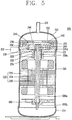
- FIG. 5 illustrates a second example of a scroll compressor employing an example of a synthetic resin bearing according to an embodiment of the present invention.
- the scroll compressor 200 includes an upper shell 212, a lower shell 214, and a casing 210.
- the upper shell 212 and the lower shell 214 are welded to the casing 210 to form an airtight space together with the casing 210.
- a discharge pipe 216 is installed on an upper portion of the upper shell 212.
- the discharge pipe 216 is a passage through which a compressed refrigerant is discharged to the outside, and an oil separator (not shown) for separating oil mixed in the discharged refrigerant may be connected to the discharge pipe 216.
- a suction pipe 218 is installed on a lateral surface of the casing 210.
- the suction pipe 218 is a passage through which a refrigerant to be compressed is introduced. In FIG. 5 , the suction pipe 218 is positioned in a boundary surface between the casing 210 and the upper shell 212, but a position thereof may be arbitrarily set.
- the lower shell 214 may also serve as an oil chamber for storing oil supplied to allow the compressor to be smoothly operated.
- a motor 220 as a driving unit is installed in a substantially central portion within the casing 210.
- the motor 220 includes a stator 222 fixed to an inner surface of the casing 210 and a rotor 224 positioned within the stator 222 and rotated according to an interaction with the stator 222.
- a rotational shaft 226 is disposed in the center of the rotor 224, and the rotor 224 and the rotational shaft 226 are rotated together.
- An oil flow path 226a is formed in a central portion of the rotational shaft 226 and extends in a length direction of the rotational shaft 226, and an oil pump 226b is installed in a lower end portion of the rotational shaft 226 to supply oil stored in the lower shell 214 upwardly.
- the oil pump 22b may be configured to have a recess having a spiral form within the oil flow path.
- the oil pump 22b may include an impeller, or a positive displacement pump may be installed as the oil pump.
- a enlarged diameter portion 226c is disposed in an upper end portion of the rotational shaft 226 such that it is insertedly positioned within a boss portion formed in the fixed scroll as described hereinafter.
- the enlarged diameter portion 226c is formed to have a diameter larger than those of other portions, and a pin portion 226d is formed in an end portion of the enlarged diameter portion 226c.
- An eccentric bearing 228 is inserted into the pin portion 226d.
- a fixed scroll 230 is installed in a boundary portion between the casing 210 and the upper shell 212.
- the fixed scroll 230 is press-fit to be fixed in a shrinkage fitting manner between the casing 210 and the upper shell 21 or may be coupled together with the casing 210 and the upper shell 212 through welding.
- a boss portion 232 is formed on a lower surface of the fixed scroll 230, in which the rotational shaft 226 is inserted.
- a through hole is formed on an upper surface (on the basis of FIG. 5 ) of the boss portion 232 to allow the pin portion 226d to penetrate therethrough. Accordingly, the pin portion 226d is protruded upwardly from a disk 234 of the fixed scroll 230 through the through hole.
- a first bearing 234 for reducing frictional contact with the rotational shaft 226 is installed on an inner surface of the boss portion 232.
- a fixed wrap 236 is formed on an upper surface of the disk 234 and enmeshed (or engaged) with an orbiting wrap as described hereinafter to form a compression chamber.
- a space portion accommodating an orbiting scroll 240 as described hereinafter is formed on an outer circumferential portion of the disk 234, and a side wall portion 38 is formed to be contiguous with an inner circumferential surface of the casing 210.
- the orbiting scroll 240 is installed above the fixed scroll 230.
- the orbiting scroll 240 includes a disk 242 having a substantially circular shape and an orbiting wrap 244 enmeshed with the fixed wrap 236.
- a rotational shaft coupling portion 246 having a substantially circular shape is formed in a central portion of the disk 242 to allow the eccentric bearing 228 is rotatably inserted and fixed therein.
- An outer circumferential portion of the rotational shaft coupling portion 246 is connected to the orbiting wrap, so it serves to form the compression chamber together with the fixed wrap during a compression process.
- the eccentric bearing 228 is inserted into the rotational shaft coupling portion 246, an end portion of the rotational shaft 226 is inserted through the disk of the fixed scroll 230, and the orbiting wrap, the fixed wrap, and the eccentric bearing 228 are installed to overlap in an lateral direction of the compressor.
- repulsive power of a refrigerant is applied to the fixed wrap and the orbiting wrap, and compressive force is applied between the rotational shaft support portion and the eccentric bearing as reaction force.
- repulsive power and compressive force of the refrigerant are applied to the same side on the basis of the disk, which are, thus, canceled out. Accordingly, the orbiting scroll may be prevented from tilting due to the action of the compressive force and repulsive power.
- a discharge hole may be formed on the disk 242 to allow a compressed refrigerant to be discharged into the casing 210.
- a position of the discharge hole may be set arbitrarily in consideration of a required discharge pressure, and the like.
- An oldhamring 250 is installed in an upper portion of the orbiting scroll 240 in order to prevent rotation of the orbiting scroll 240.
- a lower frame 260 is installed in a lower portion of the casing 210 to rotatably support the lower side of the rotational shaft 226, and an upper frame 270 is installed in an upper portion of the orbiting scroll 240 in order to support the orbiting scroll 240 and the oldhamring 250.
- a hold is formed in the center of the upper frame 270.
- the hole communicates with the discharge hole of the orbiting scroll 240 to discharge a compressed refrigerant to the upper shell 212.
- the eccentric bearing 228 and the first bearing 234 have the same shape and are formed of the same material as those of the scroll compressor according to the first embodiment of the present invention.
- the rotational shaft coupling portion is positioned in the central portion of the orbiting scroll 240, a space to be utilized as a compressive space in the disk of the orbiting scroll 240 can be significantly reduced.
- the shaft penetrating-type scroll compressor should be increased in size to obtain the same compression ratio, relative to an otherwise compressor, but according to an embodiment of the present invention, since the thickness of the bearing is reduced to half or less of that of the related art, an increase in the size of the scroll compressor can be minimized.
Landscapes
- Engineering & Computer Science (AREA)
- General Engineering & Computer Science (AREA)
- Mechanical Engineering (AREA)
- Rotary Pumps (AREA)
- Applications Or Details Of Rotary Compressors (AREA)
Claims (11)
- Kunstharzlager als ein Gleitlager (122, 132, 163, 228, 234), das an einer umlaufenden Spirale (160, 240) oder einem Hauptrahmen (120) befestigt ist und relativ bezüglich einer Drehwelle (143, 226) in einem Spiralverdichter (100, 200) gedreht wird,
dadurch gekennzeichnet, dass das Gleitlager (122, 132, 163, 228, 234) aus einem PEEK-Material besteht, das eine Wärmeleitfähigkeit von 0,5 W/mK bis 1,8 W/mK aufweist, und eine Dicke t des Gleitlagers (122, 132, 163, 228, 234) kleiner als eine Dicke t1 ist, und die Dicke t1 2 mm beträgt. - Kunstharzlager nach Anspruch 1, wobei das Gleitlager (122, 132, 163, 228, 234) während des Betriebs des Spiralverdichters (100, 200) einer Belastung von 2500 N oder mehr ausgesetzt ist.
- Kunstharzlager nach Anspruch 2, wobei t < 1 mm erfüllt ist.
- Kunstharzlager nach einem der Ansprüche 1 bis 3, wobei das Gleitlager (122, 132, 163, 228, 234) in die umlaufende Spirale (160, 240) oder den Hauptrahmen (120) eingepresst wird, um befestigt zu werden, und die Dicke t größer eine Minimaldicke t2 ist, mit der das Gleitlager (122, 132, 163, 228, 234) ohne plastische Verformung eingepresst wird.
- Kunstharzlager nach Anspruch 4, wobei, wenn die umlaufende Spirale (160, 240) oder der Hauptrahmen (120) aus Eisen bestehen, eine Einpresslänge 40 µm beträgt, und eine Maximaldehnung des PEEK-Material 20% beträgt und 0,17 mm < t erfüllt ist.
- Kunstharzlager nach einem der Ansprüche 1 bis 5, wobei die Dicke t des Gleitlagers (122, 132, 163, 228, 234) 0,17 mm < t < 1 mm erfüllt.
- Spiralverdichter (100, 200) mit:einem Gehäuse (110, 210);einem Hauptrahmen (120), der am Gehäuse befestigt ist und ein darin ausgebildetes Welleneinsatzloch aufweist;einer festen Spirale (150, 230), die am Gehäuse (110, 210) befestigt und über dem Hauptrahmen (120) angeordnet ist;einer umlaufende Spirale (160, 240), die zusammen mit der festen Spirale (150, 230) eine Verdichtungskammer (P) bildet und einen an einer unteren Fläche davon ausgebildeten Vorsprungsabschnitt (162, 232) aufweist;einer Drehachse (143, 226), die drehbar angetrieben wird und einen Endabschnitt aufweist, der im Vorsprungsabschnitt (162, 232) in einem Zustand einsatzbefestigt ist, in dem die Drehachse (143, 226) im Welleneinsatzloch einsatzangeordnet ist; undeinem Gleitlager (122, 132, 163, 228, 234), das fest in das Welleneinsatzloch und den Vorsprungsabschnitt (162, 232) eingepresst ist,dadurch gekennzeichnet, dass das Gleitlager (122, 132, 163, 228, 234) aus einem PEEK-Material gefertigt ist, das eine Wärmeleitfähigkeit von 0,5 W/mK bis 1,8 W/mK aufweist,eine Dicke t des Gleitlagers (122, 132, 163, 228, 234) t < t1 erfüllt, unddie Dicke t1 2 mm beträgt.
- Spiralverdichter (100, 200) nach Anspruch 7, wobei die Dicke t1 1 mm beträgt.
- Spiralverdichter (100, 200) nach Anspruch 7 oder 8, wobei, wenn eine Minimaldicke, mit der das Gleitlager (122, 132, 163, 228, 234) in das Welleneinsatzloch oder den Vorsprungsabschnitt (162, 232) ohne plastische Verformung eingepresst ist, t2 ist, eine Einpresslänge 40 µm beträgt und eine Maximaldehnung des PEEK-Material 20%, beträgt die Dicke t des Gleitlagers (122, 132, 163, 228, 234) t2 < t < t1 erfüllt, und die Dicke t2 0,17 mm beträgt.
- Spiralverdichter (100, 200) nach einem der Ansprüche 7 bis 9, wobei der Vorsprungsabschnitt (162, 232) so angeordnet ist, dass er mit einer umlaufenden Windung (161, 244) der umlaufenden Spirale (160, 240) komplanar ist.
- Spiralverdichter (100, 200) nach einem der Ansprüche 7 bis 10, wobei das Gleitlager (122, 132, 163, 228, 234) während des Betriebs des Spiralverdichters (100, 200) einer Belastung von 2500 N oder mehr ausgesetzt ist.
Applications Claiming Priority (2)
| Application Number | Priority Date | Filing Date | Title |
|---|---|---|---|
| KR1020120106072A KR101308753B1 (ko) | 2012-09-24 | 2012-09-24 | 합성수지제 베어링 및 이를 이용한 스크롤 압축기 |
| EP13185526.4A EP2711553B1 (de) | 2012-09-24 | 2013-09-23 | Spiralverdichter mit Kunstharzlager |
Related Parent Applications (2)
| Application Number | Title | Priority Date | Filing Date |
|---|---|---|---|
| EP13185526.4A Division-Into EP2711553B1 (de) | 2012-09-24 | 2013-09-23 | Spiralverdichter mit Kunstharzlager |
| EP13185526.4A Division EP2711553B1 (de) | 2012-09-24 | 2013-09-23 | Spiralverdichter mit Kunstharzlager |
Publications (2)
| Publication Number | Publication Date |
|---|---|
| EP3456970A1 EP3456970A1 (de) | 2019-03-20 |
| EP3456970B1 true EP3456970B1 (de) | 2020-05-13 |
Family
ID=49253115
Family Applications (2)
| Application Number | Title | Priority Date | Filing Date |
|---|---|---|---|
| EP18198600.1A Active EP3456970B1 (de) | 2012-09-24 | 2013-09-23 | Kunstharzlager und spiralverdichter damit |
| EP13185526.4A Active EP2711553B1 (de) | 2012-09-24 | 2013-09-23 | Spiralverdichter mit Kunstharzlager |
Family Applications After (1)
| Application Number | Title | Priority Date | Filing Date |
|---|---|---|---|
| EP13185526.4A Active EP2711553B1 (de) | 2012-09-24 | 2013-09-23 | Spiralverdichter mit Kunstharzlager |
Country Status (4)
| Country | Link |
|---|---|
| US (1) | US9217433B2 (de) |
| EP (2) | EP3456970B1 (de) |
| KR (1) | KR101308753B1 (de) |
| CN (1) | CN103671122B (de) |
Families Citing this family (9)
| Publication number | Priority date | Publication date | Assignee | Title |
|---|---|---|---|---|
| WO2019207617A1 (ja) * | 2018-04-23 | 2019-10-31 | 三菱電機株式会社 | スクロール圧縮機 |
| US10995753B2 (en) | 2018-05-17 | 2021-05-04 | Emerson Climate Technologies, Inc. | Compressor having capacity modulation assembly |
| US11655813B2 (en) | 2021-07-29 | 2023-05-23 | Emerson Climate Technologies, Inc. | Compressor modulation system with multi-way valve |
| US12259163B2 (en) | 2022-06-01 | 2025-03-25 | Copeland Lp | Climate-control system with thermal storage |
| US11846287B1 (en) | 2022-08-11 | 2023-12-19 | Copeland Lp | Scroll compressor with center hub |
| US11965507B1 (en) | 2022-12-15 | 2024-04-23 | Copeland Lp | Compressor and valve assembly |
| US12416308B2 (en) | 2022-12-28 | 2025-09-16 | Copeland Lp | Compressor with shutdown assembly |
| US12173708B1 (en) | 2023-12-07 | 2024-12-24 | Copeland Lp | Heat pump systems with capacity modulation |
| US12163523B1 (en) | 2023-12-15 | 2024-12-10 | Copeland Lp | Compressor and valve assembly |
Family Cites Families (15)
| Publication number | Priority date | Publication date | Assignee | Title |
|---|---|---|---|---|
| DE3343309C2 (de) | 1983-11-30 | 1989-09-21 | Glyco-Metall-Werke Daelen & Loos Gmbh, 6200 Wiesbaden | Schichtverbundwerkstoff |
| US5568983A (en) * | 1994-06-21 | 1996-10-29 | Fisher Controls International, Inc. | Peek bearing with trapped PTFE bearing liner |
| JP2000169697A (ja) * | 1998-12-08 | 2000-06-20 | Daido Metal Co Ltd | 複層軸受 |
| JP3679312B2 (ja) * | 2000-06-15 | 2005-08-03 | 大同メタル工業株式会社 | 複層摺動材料 |
| JP2002005050A (ja) | 2000-06-20 | 2002-01-09 | Fujitsu General Ltd | スクロール圧縮機 |
| JP2002005048A (ja) * | 2000-06-22 | 2002-01-09 | Hitachi Ltd | 樹脂金属複合軸受を用いたスクロール圧縮機 |
| JP2003003970A (ja) | 2001-06-20 | 2003-01-08 | Fujitsu General Ltd | スクロール圧縮機 |
| JP4485131B2 (ja) | 2003-02-17 | 2010-06-16 | 大豊工業株式会社 | すべり軸受 |
| JP3862669B2 (ja) | 2003-04-16 | 2006-12-27 | Thk株式会社 | 球面軸受の製造方法 |
| JP5339978B2 (ja) * | 2009-03-19 | 2013-11-13 | 大同メタル工業株式会社 | 冷凍機用圧縮機の軸受装置 |
| KR101667720B1 (ko) * | 2010-07-23 | 2016-10-19 | 엘지전자 주식회사 | 밀폐형 압축기 |
| JP5385873B2 (ja) * | 2010-08-11 | 2014-01-08 | 日立アプライアンス株式会社 | 冷媒圧縮機 |
| JP5635352B2 (ja) * | 2010-09-30 | 2014-12-03 | Ntn株式会社 | 複合滑り軸受 |
| JP2012122498A (ja) | 2010-12-06 | 2012-06-28 | Daido Metal Co Ltd | 摺動部材 |
| KR101059880B1 (ko) * | 2011-03-09 | 2011-08-29 | 엘지전자 주식회사 | 스크롤 압축기 |
-
2012
- 2012-09-24 KR KR1020120106072A patent/KR101308753B1/ko active Active
-
2013
- 2013-09-19 US US14/031,397 patent/US9217433B2/en active Active
- 2013-09-23 EP EP18198600.1A patent/EP3456970B1/de active Active
- 2013-09-23 EP EP13185526.4A patent/EP2711553B1/de active Active
- 2013-09-24 CN CN201310439405.0A patent/CN103671122B/zh active Active
Non-Patent Citations (1)
| Title |
|---|
| None * |
Also Published As
| Publication number | Publication date |
|---|---|
| EP2711553B1 (de) | 2018-11-21 |
| CN103671122B (zh) | 2016-02-24 |
| KR101308753B1 (ko) | 2013-09-12 |
| CN103671122A (zh) | 2014-03-26 |
| EP2711553A2 (de) | 2014-03-26 |
| US20140086777A1 (en) | 2014-03-27 |
| US9217433B2 (en) | 2015-12-22 |
| EP3456970A1 (de) | 2019-03-20 |
| EP2711553A3 (de) | 2017-06-14 |
Similar Documents
| Publication | Publication Date | Title |
|---|---|---|
| EP2711553B1 (de) | Spiralverdichter mit Kunstharzlager | |
| US9057365B2 (en) | Bush bearing fabricating method thereof and hermetic compressor having the same | |
| EP2390507B1 (de) | Shaft Lagerspiel für einen hermetischen Verdichter | |
| EP2711554B1 (de) | Spiralverdichter mit Lager | |
| JP4514493B2 (ja) | スクロール型流体機械 | |
| US9291164B2 (en) | Scroll compressor having a bush bearing provided on a boss of orbiting scroll | |
| JP2008261374A (ja) | 摺動部材およびそれを用いた流体機械 | |
| AU2006223991A1 (en) | Composition for sliding element, sliding element and fluid machine | |
| US8419286B2 (en) | Hermetic compressor | |
| JP6521048B2 (ja) | スクロール圧縮機 | |
| JP5963854B2 (ja) | 回転機械および冷凍サイクル機器 | |
| WO2015025416A1 (ja) | 回転機械及び冷凍サイクル機器 | |
| JP2008208812A (ja) | 密閉形圧縮機及び冷蔵庫 | |
| JP2005307902A (ja) | ベーンロータリ型真空ポンプ | |
| JP4032694B2 (ja) | スクロール圧縮機 | |
| JP7373939B2 (ja) | スクロール圧縮機 | |
| JP2018165507A (ja) | スクロール型圧縮機 | |
| JP2020007928A (ja) | スクロール圧縮機 | |
| JP2005133586A (ja) | 密閉型冷媒圧縮機 | |
| JPWO2017098567A1 (ja) | 圧縮機及び冷凍サイクル装置 | |
| JP2010053844A (ja) | スクロール式流体機械 | |
| JP2022043621A (ja) | 密閉型圧縮機 | |
| JP2008280846A (ja) | 密閉型冷媒圧縮機 | |
| JP2004052576A (ja) | スクロール圧縮機 | |
| JP2018017125A (ja) | 圧縮機 |
Legal Events
| Date | Code | Title | Description |
|---|---|---|---|
| PUAI | Public reference made under article 153(3) epc to a published international application that has entered the european phase |
Free format text: ORIGINAL CODE: 0009012 |
|
| STAA | Information on the status of an ep patent application or granted ep patent |
Free format text: STATUS: THE APPLICATION HAS BEEN PUBLISHED |
|
| AC | Divisional application: reference to earlier application |
Ref document number: 2711553 Country of ref document: EP Kind code of ref document: P |
|
| AK | Designated contracting states |
Kind code of ref document: A1 Designated state(s): AL AT BE BG CH CY CZ DE DK EE ES FI FR GB GR HR HU IE IS IT LI LT LU LV MC MK MT NL NO PL PT RO RS SE SI SK SM TR |
|
| STAA | Information on the status of an ep patent application or granted ep patent |
Free format text: STATUS: REQUEST FOR EXAMINATION WAS MADE |
|
| 17P | Request for examination filed |
Effective date: 20190919 |
|
| RBV | Designated contracting states (corrected) |
Designated state(s): AL AT BE BG CH CY CZ DE DK EE ES FI FR GB GR HR HU IE IS IT LI LT LU LV MC MK MT NL NO PL PT RO RS SE SI SK SM TR |
|
| GRAP | Despatch of communication of intention to grant a patent |
Free format text: ORIGINAL CODE: EPIDOSNIGR1 |
|
| STAA | Information on the status of an ep patent application or granted ep patent |
Free format text: STATUS: GRANT OF PATENT IS INTENDED |
|
| RIC1 | Information provided on ipc code assigned before grant |
Ipc: F04C 15/00 20060101AFI20191115BHEP Ipc: F04C 18/02 20060101ALI20191115BHEP Ipc: F04C 23/00 20060101ALN20191115BHEP Ipc: F04C 29/02 20060101ALN20191115BHEP Ipc: F16C 33/20 20060101ALI20191115BHEP |
|
| RIC1 | Information provided on ipc code assigned before grant |
Ipc: F04C 15/00 20060101AFI20191128BHEP Ipc: F04C 23/00 20060101ALN20191128BHEP Ipc: F04C 29/02 20060101ALN20191128BHEP Ipc: F16C 33/20 20060101ALI20191128BHEP Ipc: F04C 18/02 20060101ALI20191128BHEP |
|
| INTG | Intention to grant announced |
Effective date: 20191209 |
|
| GRAS | Grant fee paid |
Free format text: ORIGINAL CODE: EPIDOSNIGR3 |
|
| GRAA | (expected) grant |
Free format text: ORIGINAL CODE: 0009210 |
|
| STAA | Information on the status of an ep patent application or granted ep patent |
Free format text: STATUS: THE PATENT HAS BEEN GRANTED |
|
| AC | Divisional application: reference to earlier application |
Ref document number: 2711553 Country of ref document: EP Kind code of ref document: P |
|
| AK | Designated contracting states |
Kind code of ref document: B1 Designated state(s): AL AT BE BG CH CY CZ DE DK EE ES FI FR GB GR HR HU IE IS IT LI LT LU LV MC MK MT NL NO PL PT RO RS SE SI SK SM TR |
|
| REG | Reference to a national code |
Ref country code: GB Ref legal event code: FG4D |
|
| REG | Reference to a national code |
Ref country code: CH Ref legal event code: EP |
|
| REG | Reference to a national code |
Ref country code: DE Ref legal event code: R096 Ref document number: 602013069199 Country of ref document: DE |
|
| REG | Reference to a national code |
Ref country code: AT Ref legal event code: REF Ref document number: 1270650 Country of ref document: AT Kind code of ref document: T Effective date: 20200615 |
|
| REG | Reference to a national code |
Ref country code: LT Ref legal event code: MG4D |
|
| REG | Reference to a national code |
Ref country code: NL Ref legal event code: MP Effective date: 20200513 |
|
| PG25 | Lapsed in a contracting state [announced via postgrant information from national office to epo] |
Ref country code: SE Free format text: LAPSE BECAUSE OF FAILURE TO SUBMIT A TRANSLATION OF THE DESCRIPTION OR TO PAY THE FEE WITHIN THE PRESCRIBED TIME-LIMIT Effective date: 20200513 Ref country code: GR Free format text: LAPSE BECAUSE OF FAILURE TO SUBMIT A TRANSLATION OF THE DESCRIPTION OR TO PAY THE FEE WITHIN THE PRESCRIBED TIME-LIMIT Effective date: 20200814 Ref country code: LT Free format text: LAPSE BECAUSE OF FAILURE TO SUBMIT A TRANSLATION OF THE DESCRIPTION OR TO PAY THE FEE WITHIN THE PRESCRIBED TIME-LIMIT Effective date: 20200513 Ref country code: IS Free format text: LAPSE BECAUSE OF FAILURE TO SUBMIT A TRANSLATION OF THE DESCRIPTION OR TO PAY THE FEE WITHIN THE PRESCRIBED TIME-LIMIT Effective date: 20200913 Ref country code: FI Free format text: LAPSE BECAUSE OF FAILURE TO SUBMIT A TRANSLATION OF THE DESCRIPTION OR TO PAY THE FEE WITHIN THE PRESCRIBED TIME-LIMIT Effective date: 20200513 Ref country code: NO Free format text: LAPSE BECAUSE OF FAILURE TO SUBMIT A TRANSLATION OF THE DESCRIPTION OR TO PAY THE FEE WITHIN THE PRESCRIBED TIME-LIMIT Effective date: 20200813 Ref country code: PT Free format text: LAPSE BECAUSE OF FAILURE TO SUBMIT A TRANSLATION OF THE DESCRIPTION OR TO PAY THE FEE WITHIN THE PRESCRIBED TIME-LIMIT Effective date: 20200914 |
|
| PG25 | Lapsed in a contracting state [announced via postgrant information from national office to epo] |
Ref country code: HR Free format text: LAPSE BECAUSE OF FAILURE TO SUBMIT A TRANSLATION OF THE DESCRIPTION OR TO PAY THE FEE WITHIN THE PRESCRIBED TIME-LIMIT Effective date: 20200513 Ref country code: LV Free format text: LAPSE BECAUSE OF FAILURE TO SUBMIT A TRANSLATION OF THE DESCRIPTION OR TO PAY THE FEE WITHIN THE PRESCRIBED TIME-LIMIT Effective date: 20200513 Ref country code: BG Free format text: LAPSE BECAUSE OF FAILURE TO SUBMIT A TRANSLATION OF THE DESCRIPTION OR TO PAY THE FEE WITHIN THE PRESCRIBED TIME-LIMIT Effective date: 20200813 Ref country code: RS Free format text: LAPSE BECAUSE OF FAILURE TO SUBMIT A TRANSLATION OF THE DESCRIPTION OR TO PAY THE FEE WITHIN THE PRESCRIBED TIME-LIMIT Effective date: 20200513 |
|
| REG | Reference to a national code |
Ref country code: AT Ref legal event code: MK05 Ref document number: 1270650 Country of ref document: AT Kind code of ref document: T Effective date: 20200513 |
|
| PG25 | Lapsed in a contracting state [announced via postgrant information from national office to epo] |
Ref country code: AL Free format text: LAPSE BECAUSE OF FAILURE TO SUBMIT A TRANSLATION OF THE DESCRIPTION OR TO PAY THE FEE WITHIN THE PRESCRIBED TIME-LIMIT Effective date: 20200513 Ref country code: NL Free format text: LAPSE BECAUSE OF FAILURE TO SUBMIT A TRANSLATION OF THE DESCRIPTION OR TO PAY THE FEE WITHIN THE PRESCRIBED TIME-LIMIT Effective date: 20200513 |
|
| PG25 | Lapsed in a contracting state [announced via postgrant information from national office to epo] |
Ref country code: CZ Free format text: LAPSE BECAUSE OF FAILURE TO SUBMIT A TRANSLATION OF THE DESCRIPTION OR TO PAY THE FEE WITHIN THE PRESCRIBED TIME-LIMIT Effective date: 20200513 Ref country code: RO Free format text: LAPSE BECAUSE OF FAILURE TO SUBMIT A TRANSLATION OF THE DESCRIPTION OR TO PAY THE FEE WITHIN THE PRESCRIBED TIME-LIMIT Effective date: 20200513 Ref country code: ES Free format text: LAPSE BECAUSE OF FAILURE TO SUBMIT A TRANSLATION OF THE DESCRIPTION OR TO PAY THE FEE WITHIN THE PRESCRIBED TIME-LIMIT Effective date: 20200513 Ref country code: AT Free format text: LAPSE BECAUSE OF FAILURE TO SUBMIT A TRANSLATION OF THE DESCRIPTION OR TO PAY THE FEE WITHIN THE PRESCRIBED TIME-LIMIT Effective date: 20200513 Ref country code: EE Free format text: LAPSE BECAUSE OF FAILURE TO SUBMIT A TRANSLATION OF THE DESCRIPTION OR TO PAY THE FEE WITHIN THE PRESCRIBED TIME-LIMIT Effective date: 20200513 Ref country code: SM Free format text: LAPSE BECAUSE OF FAILURE TO SUBMIT A TRANSLATION OF THE DESCRIPTION OR TO PAY THE FEE WITHIN THE PRESCRIBED TIME-LIMIT Effective date: 20200513 Ref country code: IT Free format text: LAPSE BECAUSE OF FAILURE TO SUBMIT A TRANSLATION OF THE DESCRIPTION OR TO PAY THE FEE WITHIN THE PRESCRIBED TIME-LIMIT Effective date: 20200513 Ref country code: DK Free format text: LAPSE BECAUSE OF FAILURE TO SUBMIT A TRANSLATION OF THE DESCRIPTION OR TO PAY THE FEE WITHIN THE PRESCRIBED TIME-LIMIT Effective date: 20200513 |
|
| REG | Reference to a national code |
Ref country code: DE Ref legal event code: R097 Ref document number: 602013069199 Country of ref document: DE |
|
| PG25 | Lapsed in a contracting state [announced via postgrant information from national office to epo] |
Ref country code: SK Free format text: LAPSE BECAUSE OF FAILURE TO SUBMIT A TRANSLATION OF THE DESCRIPTION OR TO PAY THE FEE WITHIN THE PRESCRIBED TIME-LIMIT Effective date: 20200513 Ref country code: PL Free format text: LAPSE BECAUSE OF FAILURE TO SUBMIT A TRANSLATION OF THE DESCRIPTION OR TO PAY THE FEE WITHIN THE PRESCRIBED TIME-LIMIT Effective date: 20200513 |
|
| PLBE | No opposition filed within time limit |
Free format text: ORIGINAL CODE: 0009261 |
|
| STAA | Information on the status of an ep patent application or granted ep patent |
Free format text: STATUS: NO OPPOSITION FILED WITHIN TIME LIMIT |
|
| 26N | No opposition filed |
Effective date: 20210216 |
|
| REG | Reference to a national code |
Ref country code: CH Ref legal event code: PL |
|
| GBPC | Gb: european patent ceased through non-payment of renewal fee |
Effective date: 20200923 |
|
| PG25 | Lapsed in a contracting state [announced via postgrant information from national office to epo] |
Ref country code: SI Free format text: LAPSE BECAUSE OF FAILURE TO SUBMIT A TRANSLATION OF THE DESCRIPTION OR TO PAY THE FEE WITHIN THE PRESCRIBED TIME-LIMIT Effective date: 20200513 |
|
| REG | Reference to a national code |
Ref country code: BE Ref legal event code: MM Effective date: 20200930 |
|
| PG25 | Lapsed in a contracting state [announced via postgrant information from national office to epo] |
Ref country code: LU Free format text: LAPSE BECAUSE OF NON-PAYMENT OF DUE FEES Effective date: 20200923 |
|
| PG25 | Lapsed in a contracting state [announced via postgrant information from national office to epo] |
Ref country code: FR Free format text: LAPSE BECAUSE OF NON-PAYMENT OF DUE FEES Effective date: 20200930 |
|
| PG25 | Lapsed in a contracting state [announced via postgrant information from national office to epo] |
Ref country code: IE Free format text: LAPSE BECAUSE OF NON-PAYMENT OF DUE FEES Effective date: 20200923 Ref country code: CH Free format text: LAPSE BECAUSE OF NON-PAYMENT OF DUE FEES Effective date: 20200930 Ref country code: LI Free format text: LAPSE BECAUSE OF NON-PAYMENT OF DUE FEES Effective date: 20200930 Ref country code: GB Free format text: LAPSE BECAUSE OF NON-PAYMENT OF DUE FEES Effective date: 20200923 Ref country code: BE Free format text: LAPSE BECAUSE OF NON-PAYMENT OF DUE FEES Effective date: 20200930 |
|
| PG25 | Lapsed in a contracting state [announced via postgrant information from national office to epo] |
Ref country code: TR Free format text: LAPSE BECAUSE OF FAILURE TO SUBMIT A TRANSLATION OF THE DESCRIPTION OR TO PAY THE FEE WITHIN THE PRESCRIBED TIME-LIMIT Effective date: 20200513 Ref country code: MT Free format text: LAPSE BECAUSE OF FAILURE TO SUBMIT A TRANSLATION OF THE DESCRIPTION OR TO PAY THE FEE WITHIN THE PRESCRIBED TIME-LIMIT Effective date: 20200513 Ref country code: CY Free format text: LAPSE BECAUSE OF FAILURE TO SUBMIT A TRANSLATION OF THE DESCRIPTION OR TO PAY THE FEE WITHIN THE PRESCRIBED TIME-LIMIT Effective date: 20200513 |
|
| PG25 | Lapsed in a contracting state [announced via postgrant information from national office to epo] |
Ref country code: MK Free format text: LAPSE BECAUSE OF FAILURE TO SUBMIT A TRANSLATION OF THE DESCRIPTION OR TO PAY THE FEE WITHIN THE PRESCRIBED TIME-LIMIT Effective date: 20200513 Ref country code: MC Free format text: LAPSE BECAUSE OF FAILURE TO SUBMIT A TRANSLATION OF THE DESCRIPTION OR TO PAY THE FEE WITHIN THE PRESCRIBED TIME-LIMIT Effective date: 20200513 |
|
| PGFP | Annual fee paid to national office [announced via postgrant information from national office to epo] |
Ref country code: DE Payment date: 20250805 Year of fee payment: 13 |