EP3456397B1 - Stoffaustauschmaschine - Google Patents
Stoffaustauschmaschine Download PDFInfo
- Publication number
- EP3456397B1 EP3456397B1 EP18000606.6A EP18000606A EP3456397B1 EP 3456397 B1 EP3456397 B1 EP 3456397B1 EP 18000606 A EP18000606 A EP 18000606A EP 3456397 B1 EP3456397 B1 EP 3456397B1
- Authority
- EP
- European Patent Office
- Prior art keywords
- rotor
- channels
- tubes
- liquid
- gas
- Prior art date
- Legal status (The legal status is an assumption and is not a legal conclusion. Google has not performed a legal analysis and makes no representation as to the accuracy of the status listed.)
- Active
Links
Images

Classifications
-
- B—PERFORMING OPERATIONS; TRANSPORTING
- B01—PHYSICAL OR CHEMICAL PROCESSES OR APPARATUS IN GENERAL
- B01D—SEPARATION
- B01D3/00—Distillation or related exchange processes in which liquids are contacted with gaseous media, e.g. stripping
- B01D3/14—Fractional distillation or use of a fractionation or rectification column
- B01D3/30—Fractionating columns with movable parts or in which centrifugal movement is caused
-
- B—PERFORMING OPERATIONS; TRANSPORTING
- B01—PHYSICAL OR CHEMICAL PROCESSES OR APPARATUS IN GENERAL
- B01D—SEPARATION
- B01D3/00—Distillation or related exchange processes in which liquids are contacted with gaseous media, e.g. stripping
- B01D3/08—Distillation or related exchange processes in which liquids are contacted with gaseous media, e.g. stripping in rotating vessels; Atomisation on rotating discs
-
- B—PERFORMING OPERATIONS; TRANSPORTING
- B01—PHYSICAL OR CHEMICAL PROCESSES OR APPARATUS IN GENERAL
- B01F—MIXING, e.g. DISSOLVING, EMULSIFYING OR DISPERSING
- B01F23/00—Mixing according to the phases to be mixed, e.g. dispersing or emulsifying
- B01F23/20—Mixing gases with liquids
- B01F23/23—Mixing gases with liquids by introducing gases into liquid media, e.g. for producing aerated liquids
- B01F23/233—Mixing gases with liquids by introducing gases into liquid media, e.g. for producing aerated liquids using driven stirrers with completely immersed stirring elements
-
- B—PERFORMING OPERATIONS; TRANSPORTING
- B01—PHYSICAL OR CHEMICAL PROCESSES OR APPARATUS IN GENERAL
- B01J—CHEMICAL OR PHYSICAL PROCESSES, e.g. CATALYSIS OR COLLOID CHEMISTRY; THEIR RELEVANT APPARATUS
- B01J19/00—Chemical, physical or physico-chemical processes in general; Their relevant apparatus
- B01J19/18—Stationary reactors having moving elements inside
- B01J19/1806—Stationary reactors having moving elements inside resulting in a turbulent flow of the reactants, such as in centrifugal-type reactors, or having a high Reynolds-number
-
- B—PERFORMING OPERATIONS; TRANSPORTING
- B01—PHYSICAL OR CHEMICAL PROCESSES OR APPARATUS IN GENERAL
- B01J—CHEMICAL OR PHYSICAL PROCESSES, e.g. CATALYSIS OR COLLOID CHEMISTRY; THEIR RELEVANT APPARATUS
- B01J19/00—Chemical, physical or physico-chemical processes in general; Their relevant apparatus
- B01J19/28—Moving reactors, e.g. rotary drums
-
- B—PERFORMING OPERATIONS; TRANSPORTING
- B01—PHYSICAL OR CHEMICAL PROCESSES OR APPARATUS IN GENERAL
- B01J—CHEMICAL OR PHYSICAL PROCESSES, e.g. CATALYSIS OR COLLOID CHEMISTRY; THEIR RELEVANT APPARATUS
- B01J19/00—Chemical, physical or physico-chemical processes in general; Their relevant apparatus
- B01J19/30—Loose or shaped packing elements, e.g. Raschig rings or Berl saddles, for pouring into the apparatus for mass or heat transfer
-
- B—PERFORMING OPERATIONS; TRANSPORTING
- B01—PHYSICAL OR CHEMICAL PROCESSES OR APPARATUS IN GENERAL
- B01J—CHEMICAL OR PHYSICAL PROCESSES, e.g. CATALYSIS OR COLLOID CHEMISTRY; THEIR RELEVANT APPARATUS
- B01J19/00—Chemical, physical or physico-chemical processes in general; Their relevant apparatus
- B01J19/32—Packing elements in the form of grids or built-up elements for forming a unit or module inside the apparatus for mass or heat transfer
-
- B—PERFORMING OPERATIONS; TRANSPORTING
- B01—PHYSICAL OR CHEMICAL PROCESSES OR APPARATUS IN GENERAL
- B01F—MIXING, e.g. DISSOLVING, EMULSIFYING OR DISPERSING
- B01F23/00—Mixing according to the phases to be mixed, e.g. dispersing or emulsifying
- B01F23/20—Mixing gases with liquids
- B01F23/23—Mixing gases with liquids by introducing gases into liquid media, e.g. for producing aerated liquids
- B01F23/233—Mixing gases with liquids by introducing gases into liquid media, e.g. for producing aerated liquids using driven stirrers with completely immersed stirring elements
- B01F23/2335—Mixing gases with liquids by introducing gases into liquid media, e.g. for producing aerated liquids using driven stirrers with completely immersed stirring elements characterised by the direction of introduction of the gas relative to the stirrer
- B01F23/23353—Mixing gases with liquids by introducing gases into liquid media, e.g. for producing aerated liquids using driven stirrers with completely immersed stirring elements characterised by the direction of introduction of the gas relative to the stirrer the gas being sucked towards the rotating stirrer
-
- B—PERFORMING OPERATIONS; TRANSPORTING
- B01—PHYSICAL OR CHEMICAL PROCESSES OR APPARATUS IN GENERAL
- B01F—MIXING, e.g. DISSOLVING, EMULSIFYING OR DISPERSING
- B01F23/00—Mixing according to the phases to be mixed, e.g. dispersing or emulsifying
- B01F23/20—Mixing gases with liquids
- B01F23/23—Mixing gases with liquids by introducing gases into liquid media, e.g. for producing aerated liquids
- B01F23/233—Mixing gases with liquids by introducing gases into liquid media, e.g. for producing aerated liquids using driven stirrers with completely immersed stirring elements
- B01F23/2336—Mixing gases with liquids by introducing gases into liquid media, e.g. for producing aerated liquids using driven stirrers with completely immersed stirring elements characterised by the location of the place of introduction of the gas relative to the stirrer
- B01F23/23365—Mixing gases with liquids by introducing gases into liquid media, e.g. for producing aerated liquids using driven stirrers with completely immersed stirring elements characterised by the location of the place of introduction of the gas relative to the stirrer the gas being introduced at the radial periphery of the stirrer
-
- B—PERFORMING OPERATIONS; TRANSPORTING
- B01—PHYSICAL OR CHEMICAL PROCESSES OR APPARATUS IN GENERAL
- B01J—CHEMICAL OR PHYSICAL PROCESSES, e.g. CATALYSIS OR COLLOID CHEMISTRY; THEIR RELEVANT APPARATUS
- B01J2219/00—Chemical, physical or physico-chemical processes in general; Their relevant apparatus
- B01J2219/30—Details relating to random packing elements
- B01J2219/304—Composition or microstructure of the elements
- B01J2219/30483—Fibrous materials
-
- B—PERFORMING OPERATIONS; TRANSPORTING
- B01—PHYSICAL OR CHEMICAL PROCESSES OR APPARATUS IN GENERAL
- B01J—CHEMICAL OR PHYSICAL PROCESSES, e.g. CATALYSIS OR COLLOID CHEMISTRY; THEIR RELEVANT APPARATUS
- B01J2219/00—Chemical, physical or physico-chemical processes in general; Their relevant apparatus
- B01J2219/30—Details relating to random packing elements
- B01J2219/304—Composition or microstructure of the elements
- B01J2219/30491—Foam like materials
-
- B—PERFORMING OPERATIONS; TRANSPORTING
- B01—PHYSICAL OR CHEMICAL PROCESSES OR APPARATUS IN GENERAL
- B01J—CHEMICAL OR PHYSICAL PROCESSES, e.g. CATALYSIS OR COLLOID CHEMISTRY; THEIR RELEVANT APPARATUS
- B01J2219/00—Chemical, physical or physico-chemical processes in general; Their relevant apparatus
- B01J2219/32—Details relating to packing elements in the form of grids or built-up elements for forming a unit of module inside the apparatus for mass or heat transfer
- B01J2219/322—Basic shape of the elements
- B01J2219/32203—Sheets
-
- B—PERFORMING OPERATIONS; TRANSPORTING
- B01—PHYSICAL OR CHEMICAL PROCESSES OR APPARATUS IN GENERAL
- B01J—CHEMICAL OR PHYSICAL PROCESSES, e.g. CATALYSIS OR COLLOID CHEMISTRY; THEIR RELEVANT APPARATUS
- B01J2219/00—Chemical, physical or physico-chemical processes in general; Their relevant apparatus
- B01J2219/32—Details relating to packing elements in the form of grids or built-up elements for forming a unit of module inside the apparatus for mass or heat transfer
- B01J2219/324—Composition or microstructure of the elements
- B01J2219/32408—Metal
- B01J2219/32416—Metal fibrous
-
- B—PERFORMING OPERATIONS; TRANSPORTING
- B01—PHYSICAL OR CHEMICAL PROCESSES OR APPARATUS IN GENERAL
- B01J—CHEMICAL OR PHYSICAL PROCESSES, e.g. CATALYSIS OR COLLOID CHEMISTRY; THEIR RELEVANT APPARATUS
- B01J2219/00—Chemical, physical or physico-chemical processes in general; Their relevant apparatus
- B01J2219/32—Details relating to packing elements in the form of grids or built-up elements for forming a unit of module inside the apparatus for mass or heat transfer
- B01J2219/324—Composition or microstructure of the elements
- B01J2219/32441—Glass
-
- B—PERFORMING OPERATIONS; TRANSPORTING
- B01—PHYSICAL OR CHEMICAL PROCESSES OR APPARATUS IN GENERAL
- B01J—CHEMICAL OR PHYSICAL PROCESSES, e.g. CATALYSIS OR COLLOID CHEMISTRY; THEIR RELEVANT APPARATUS
- B01J2219/00—Chemical, physical or physico-chemical processes in general; Their relevant apparatus
- B01J2219/32—Details relating to packing elements in the form of grids or built-up elements for forming a unit of module inside the apparatus for mass or heat transfer
- B01J2219/324—Composition or microstructure of the elements
- B01J2219/32483—Plastics
-
- B—PERFORMING OPERATIONS; TRANSPORTING
- B01—PHYSICAL OR CHEMICAL PROCESSES OR APPARATUS IN GENERAL
- B01J—CHEMICAL OR PHYSICAL PROCESSES, e.g. CATALYSIS OR COLLOID CHEMISTRY; THEIR RELEVANT APPARATUS
- B01J2219/00—Chemical, physical or physico-chemical processes in general; Their relevant apparatus
- B01J2219/32—Details relating to packing elements in the form of grids or built-up elements for forming a unit of module inside the apparatus for mass or heat transfer
- B01J2219/324—Composition or microstructure of the elements
- B01J2219/32491—Woven or knitted materials
Definitions
- the invention relates to a device for effecting a mass transfer between a liquid and a gas within a rotor, wherein the liquid in the center of the rotor is abandoned and driven by the centrifugal force generated by the rotor rotation to the outside, and wherein the gas surrounds the rotor and through the Gas pressure is pressed by the rotor from outside to inside, against the liquid flow in the rotor.
- Mass transfer machines are known with a rotor having two side surfaces, wherein in the space between the two surfaces is a pack that drives centrally discontinued liquid at rotor rotation to the outside.
- the rotor is surrounded by a gas which flows through the rotor by the gas pressure against the liquid in order to effect a mass transfer between the liquid and the gas.
- the object of the invention is to provide a device of the type mentioned, in which the mass transfer and the mass transfer is substantially improved, with ease of manufacture and assembly.
- the rotor has a plurality of lying in the rotor plane channels in the form of tubes that begin in the rotor center and end in the cylindrical annular surface of the rotor outer circumference, wherein the tubes are each filled with a package, the contact surface between the Increased liquid and the gas, and that the rotor has two circular side surfaces to which the rotor rotational axis is perpendicular and which together form a gap in which the tubes are arranged.
- the packs in the tubular channels are woven, knitted, screen or grid-shaped.
- the particular tubular channels and in particular smooth or structured inlaid packings of metal in particular formed by structural plates or made of plastic or glass fiber.
- the inner ends of the channels or tubes form an inner coaxial space into which the liquid is fed. It is advantageous if the tubes / channels are arranged in the rotor in particular in the rotor center such that the liquid flows through the rotor only through the channels.
- the rotor preferably has one to thirty-two, preferably four to eight, channels, in particular tubes.
- the tubes / channels may expand continuously or stepwise outwardly. Further, the tubes / channels may be composed of individual separate sections.
- the mass transfer machine has a rotor 1, which has two mutually coaxial and parallel circular side surfaces 2, 3 or side windows of the same diameter, which form between them a narrow gap 4 of constant width. Both surfaces / discs 2, 3 are mounted vertically in a manner not shown on a central shaft and each have a central opening 5 on.
- the channels 7 form.
- the radial tubes begin with their inner end at the edge of the opening 5 and end with its outer end in the outer coaxial cylindrical annular surface 8 of the rotor 1.
- the inner ends of the tubes / channels form with the openings 5 an inner coaxial interior 9, in the the liquid will give up.
- the outer ends of the tubes 6 terminate in the outer cylindrical annular surface 8 of the rotor. In this case, it is ensured that the tubes 6 / the channels 7 are arranged in the rotor 1 in particular in the rotor center such that the liquid only flows through the channels through the rotor.
- All tubes 6 are filled with a pack, not shown, the object of which is to increase the contact surface between the discontinued in the interior 9 liquid with the externally acting gas in particular to effect a mass transfer optimal.
- the packs in the particular tubular channels 7 are woven, knitted, screen or grid-shaped.
- the in particular tubular channels 7 inlaid packages of metal, in particular of structural sheets or plastic or glass fiber.
- the channels 7 are formed by tubes 6 made of metal or plastic, which are arranged radially or obliquely in the rotor 1. In the two embodiments, eight tubes / channels are mounted between the discs / surfaces 2. The number can be between one pipe / channel and thirty-two.
- the tubes 6 / channels 7 expand continuously outwardly or in steps. Also, the tubes 6 / channels 7 can expand continuously or gradually outward. Further, the tubes / channels may be composed of individual separate sections.
- the rotor 1 with its tubes / channels made of metal and / or plastic, is mounted in a closed gasbeetzten chamber and driven by an electric motor.
Landscapes
- Chemical & Material Sciences (AREA)
- Chemical Kinetics & Catalysis (AREA)
- Organic Chemistry (AREA)
- Physics & Mathematics (AREA)
- Thermal Sciences (AREA)
- Physical Or Chemical Processes And Apparatus (AREA)
- Centrifugal Separators (AREA)
- Structures Of Non-Positive Displacement Pumps (AREA)
- Vaporization, Distillation, Condensation, Sublimation, And Cold Traps (AREA)
- Disintegrating Or Milling (AREA)
- Fish Paste Products (AREA)
- Confectionery (AREA)
- Separation Of Solids By Using Liquids Or Pneumatic Power (AREA)
Description
- Die Erfindung betrifft eine Vorrichtung zum Bewirken eines Stoffaustausches zwischen einer Flüssigkeit und einem Gas innerhalb eines Rotors, wobei die Flüssigkeit im Zentrum des Rotors aufgegeben und durch die von der Rotordrehung erzeugte Zentrifugalkraft nach außen getrieben wird, und wobei das Gas den Rotor umgibt und durch den Gasdruck durch den Rotor hindurch von außen nach innen gedrückt wird, entgegen der Flüssigkeitsströmung im Rotor.
- Aus der
WO 2015/101826 A1 undWO 2016/038480 A1 sind Stoffaustauschmaschinen bekannt mit einem Rotor, der zwei Seitenflächen aufweist, wobei im Zwischenraum zwischen den beiden Flächen sich eine Packung befindet, die bei Rotordrehung zentral aufgegebene Flüssigkeit nach außen treibt. Hierbei ist der Rotor von einem Gas umgeben, das durch den Gasdruck entgegen der Flüssigkeit durch den Rotor strömt, um einen Stoffaustausch zwischen der Flüssigkeit und dem Gas zu bewirken. - Dokumente
EP 0 089 128 A1 undUS 5 363 909 A offenbaren auch Stoffaustauschmaschinen mit einem Rotor. - Aufgabe der Erfindung ist es, eine Vorrichtung der eingangs genannten Art zu schaffen, bei der der Stoffaustausch und der Stofftransport wesentlich verbessert ist, bei einfacher Herstellung und Montage.
- Diese Aufgabe wird erfindungsgemäß dadurch gelöst, dass der Rotor mehrere in der Rotorebene liegende Kanäle in Form von Rohren aufweist, die im Rotorzentrum beginnen und in der zylindrischen Ringfläche des Rotoraußenumfangs enden, wobei die Rohre jeweils mit einer Packung gefüllt sind, die die Kontaktfläche zwischen der Flüssigkeit und dem Gas vergrößert, und dass der Rotor zwei kreisrunde Seitenflächen aufweist, zu denen die Rotorendrehachse lotrecht ist und die miteinander einen Zwischenraum bilden, in dem die Rohre angeordnet sind.
- Das Aufteilen der Rotorenpackung in einzelne Packungsbereiche innerhalb von radialen oder schrägen Kanälen innerhalb des Rotors ermöglicht einen besonders präzisen und effektiven Stoffaustausch bei einfacher Herstellung und Montage des Rotors.
- Hierzu ist es besonders vorteilhaft, wenn die in den insbesondere rohrförmigen Kanälen einliegenden Packungen gewebe-, gestricke-, sieb- oder gitterförmig sind. Hierbei bestehen die in den insbesondere rohrförmigen Kanälen und insbesondere glatt oder strukturiert einliegenden Packungen aus Metall insbesondere von Strukturblechen gebildet oder aus Kunststoff oder Glasfaser.
- Vorzugsweise wird vorgeschlagen, dass die inneren Enden der Kanäle oder Rohre einen inneren koaxialen Raum bilden, in den die Flüssigkeit aufgegeben wird. Hierbei ist von Vorteil, wenn die Rohre/die Kanäle im Rotor insbesondere im Rotorzentrum derart angeordnet sind, dass die Flüssigkeit nur durch die Kanäle durch den Rotor strömt.
- Vorzugsweise weist der Rotor ein bis zweiunddreißig, vorzugsweise vier bis acht Kanäle insbesondere Rohre auf.
- Auch können die Rohre/die Kanäle sich nach außen hin kontinuierlich oder stufenweise erweitern. Ferner können die Rohre/die Kanäle aus einzelnen separaten Abschnitten zusammengesetzt sein.
- Eine vorteilhafte Ausgestaltung des erfindungsgemäßen Rotors ist in den Zeichnungen perspektivisch dargestellt. Es zeigen
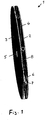
- Fig. 1
- den Rotor mit beiden Seitenflächen,
- Fig. 2
- den Rotor mit auf einer Seite abgenommener Seitenfläche.
- Die Stoffaustauschmaschine weist einen Rotor 1 auf, der zwei zueinander koaxiale und parallele kreisrunde Seitenflächen 2, 3 bzw. Seitenscheiben gleichen Durchmessers besitzt, die zwischen sich einen schmalen Zwischenraum 4 gleichbleibender Breite bilden. Beide Flächen/Scheiben 2, 3 sind in nicht dargestellter Weise auf einer mittigen Welle lotrecht befestigt und weisen jeweils eine mittige Öffnung 5 auf.
- Im Zwischenraum 4 zwischen den beiden Flächen/Scheiben 2, 3 sind mehrere Rohre 6 radial befestigt, die Kanäle 7 bilden. Die radialen Rohre beginnen mit ihrem inneren Ende am Rand der Öffnung 5 und enden mit ihrem äußeren Ende in der äußeren koaxialen zylindrischen Ringfläche 8 des Rotors 1. Die inneren Enden der Rohre/Kanäle bilden mit den Öffnungen 5 einen inneren koaxialen Innenraum 9, in den die Flüssigkeit aufgeben wird. Die äußeren Enden der Rohre 6 enden in der äußeren zylindrischen Ringfläche 8 des Rotors. Hierbei ist dafür gesorgt, dass die Rohre 6 /die Kanäle 7 im Rotor 1 insbesondere im Rotorzentrum derart angeordnet sind, dass die Flüssigkeit nur durch die Kanäle durch den Rotor strömt.
- Alle Rohre 6 sind mit einer nicht dargestellten Packung ausgefüllt, deren Aufgabe es ist, die Kontaktfläche zwischen der in den Innenraum 9 aufgegebenen Flüssigkeit mit dem von außen einwirkenden Gas zu vergrößern insbesondere um einen Stoffaustausch optimal zu bewirken. Vorzugsweise sind die in den insbesondere rohrförmigen Kanälen 7 einliegenden Packungen gewebe-, gestricke-, sieb- oder gitterförmig. Hierbei bestehen die in den insbesondere rohrförmigen Kanälen 7 einliegenden Packungen aus Metall insbesondere von Strukturblechen oder aus Kunststoff oder Glasfaser.
- Die Kanäle 7 sind von Rohren 6 aus Metall oder Kunststoff gebildet, die im Rotor 1 radial oder schräg angeordnet sind. In den zwei Ausführungsbeispielen sind acht Rohre/Kanäle zwischen den Scheiben/Flächen 2 befestigt. Die Anzahl kann zwischen einem Rohr/Kanal und zweiunddreißig liegen.
- In nicht dargestellten Ausführungen erweitern sich die Rohre 6 /die Kanäle 7 nach außen hin kontinuierlich oder stufenweise. Auch können die Rohre 6/Kanäle 7 sich nach außen kontinuierlich oder stufenweise erweitern. Ferner können die Rohre/Kanäle aus einzelnen separaten Abschnitten zusammengesetzt sein.
- In beiden Ausführungen besteht der Rotor 1 mit seinen Rohren/Kanälen aus Metall und/oder Kunststoff, ist in einer geschlossenen gasbeaufschlagten Kammer gelagert und von einem Elektromotor angetrieben.
Claims (9)
- Vorrichtung zum Bewirken eines Stoffaustausches zwischen einer Flüssigkeit und einem Gas innerhalb eines Rotors (1), wobei die Flüssigkeit im Zentrum des Rotors aufgegeben und durch die von der Rotordrehung erzeugte Zentrifugalkraft nach außen getrieben wird, und wobei das Gas den Rotor umgibt und durch den Gasdruck durch den Rotor hindurch von außen nach innen gedrückt wird entgegen der Flüssigkeitsströmung im Rotor, dadurch gekennzeichnet, dass der Rotor (1) mehrere in der Rotorebene liegende Kanäle (7) in Form von Rohren (6) aufweist, die im Rotorzentrum (9) beginnen und in der äußeren zylindrischen Ringfläche des Rotoraußenumfangs (8) enden, wobei die Rohre jeweils mit einer Packung gefüllt sind, die die Kontaktfläche zwischen der Flüssigkeit und dem Gas vergrößert, und dass der Rotor zwei kreisrunde Seitenflächen aufweist, zu denen die Rotorendrehachse lotrecht ist und die miteinander einen Zwischenraum bilden, in dem die Rohre angeordnet sind.
- Vorrichtung nach Anspruch 1, dadurch gekennzeichnet, dass die Rohre (6) aus Metall oder Kunststoff gebildet sind, die im Rotor (1) radial oder schräg angeordnet sind.
- Vorrichtung nach Anspruch 1 oder 2, dadurch gekennzeichnet, dass die in den insbesondere rohrförmigen Kanälen (7) einliegenden Packungen gewebe-, gestricke-, sieb- oder gitterförmig und insbesondere glatt oder strukturiert sind.
- Vorrichtung nach einem der vorherigen Ansprüche, dadurch gekennzeichnet, dass die in den insbesondere rohrförmigen Kanälen (7) einliegenden Packungen aus Metall insbesondere von Strukturblechen gebildet oder aus Kunststoff oder Glasfaser bestehen.
- Vorrichtung nach einem der vorherigen Ansprüche, dadurch gekennzeichnet, dass die inneren Enden der Kanäle (7) oder Rohre (6) einen inneren koaxialen Raum (9) bilden, in den die Flüssigkeit aufgegeben wird.
- Vorrichtung nach einem der vorherigen Ansprüche, dadurch gekennzeichnet, dass die Rohre (6)/die Kanäle (7) im Rotor (1) insbesondere im Rotorzentrum derart angeordnet sind, dass die Flüssigkeit nur durch die Kanäle durch den Rotor strömt.
- Vorrichtung nach einem der vorherigen Ansprüche, dadurch gekennzeichnet, dass der Rotor (1) ein bis zweiunddreißig, vorzugsweise vier bis acht Kanäle insbesondere Rohre (6) aufweist.
- Vorrichtung nach einem der vorherigen Ansprüche, dadurch gekennzeichnet, dass die Rohre (6)/die Kanäle (7) nach außen hin sich kontinuierlich oder stufenweise erweitern.
- Vorrichtung nach einem der vorherigen Ansprüche, dadurch gekennzeichnet, dass die Rohre (6)/die Kanäle (7) aus einzelnen separaten Abschnitten zusammengesetzt sind.
Applications Claiming Priority (1)
| Application Number | Priority Date | Filing Date | Title |
|---|---|---|---|
| DE102017008628.1A DE102017008628A1 (de) | 2017-09-14 | 2017-09-14 | Stoffaustauschmaschine |
Publications (2)
| Publication Number | Publication Date |
|---|---|
| EP3456397A1 EP3456397A1 (de) | 2019-03-20 |
| EP3456397B1 true EP3456397B1 (de) | 2019-11-13 |
Family
ID=63113309
Family Applications (1)
| Application Number | Title | Priority Date | Filing Date |
|---|---|---|---|
| EP18000606.6A Active EP3456397B1 (de) | 2017-09-14 | 2018-07-18 | Stoffaustauschmaschine |
Country Status (6)
| Country | Link |
|---|---|
| US (1) | US10702836B2 (de) |
| EP (1) | EP3456397B1 (de) |
| JP (1) | JP7186038B2 (de) |
| CN (1) | CN109499087B (de) |
| DE (1) | DE102017008628A1 (de) |
| TW (1) | TWI778104B (de) |
Families Citing this family (2)
| Publication number | Priority date | Publication date | Assignee | Title |
|---|---|---|---|---|
| CN113072984B (zh) * | 2021-04-21 | 2021-09-10 | 济南冶金化工设备有限公司 | 焦炉煤气超重力脱硫设备转子及设备 |
| CN114470837B (zh) * | 2022-01-25 | 2023-01-13 | 中船(邯郸)派瑞特种气体股份有限公司 | 一种高纯氘代氨电子气体制取用精馏提纯设备 |
Citations (2)
| Publication number | Priority date | Publication date | Assignee | Title |
|---|---|---|---|---|
| WO2015101826A1 (en) * | 2013-12-31 | 2015-07-09 | Hindustan Petroleum Corporation Ltd. | Rotating packed bed unit |
| WO2016038480A1 (en) * | 2014-09-09 | 2016-03-17 | Hindustan Petroleum Corporation Ltd. | Rotating packed bed assembly |
Family Cites Families (28)
| Publication number | Priority date | Publication date | Assignee | Title |
|---|---|---|---|---|
| GB265120A (en) * | 1926-01-26 | 1927-07-13 | Louise Theisen | Improvements in apparatus for producing pressure and suctional effects |
| GB757149A (en) * | 1953-06-29 | 1956-09-12 | Claes Wilhelm Pilo | Apparatus for the performance of an exchange of heat and/or soluble substances between two flowing media of different specific gravity |
| US2941872A (en) * | 1959-06-09 | 1960-06-21 | Pilo | Apparatus for intimate contacting of two fluid media having different specific weight |
| CH507197A (de) * | 1968-07-12 | 1971-05-15 | Agripat Sa | Verfahren zur Herstellung neuer Isothiocyanato-diphenylamine |
| JPS4843604Y1 (de) * | 1969-07-04 | 1973-12-17 | ||
| US3701513A (en) * | 1970-07-21 | 1972-10-31 | Shirley J Carter | Fuel feeding apparatus |
| US3991143A (en) * | 1973-07-12 | 1976-11-09 | Carter Shirley J | Apparatus for producing and delivering a combustible fuel mixture and improved nebulizer rotor |
| DE2862420D1 (en) | 1977-12-01 | 1984-07-26 | Ici Plc | Mass transfer apparatus and its use |
| ATE8341T1 (de) * | 1980-09-11 | 1984-07-15 | Imperial Chemical Industries Plc | Zentrifuge fuer gas-fluessigkeits-kontakt. |
| ATE21043T1 (de) * | 1981-10-26 | 1986-08-15 | Ici Plc | Gas-fluessigkeits-zentrifugalreaktor. |
| DE3268599D1 (en) * | 1981-11-24 | 1986-02-27 | Ici Plc | Contacting device |
| GB8304901D0 (en) * | 1982-03-12 | 1983-03-23 | Ici Plc | Displacing dissolved gas from water |
| USRE32562E (en) * | 1982-07-08 | 1987-12-15 | Union Carbide Corporation | Process and apparatus for mixing a gas and a liquid |
| US5363909A (en) * | 1991-11-27 | 1994-11-15 | Praxair Technology, Inc. | Compact contacting device |
| US6048513A (en) * | 1996-09-11 | 2000-04-11 | The Dow Chemical Company | Method for synthesis of hypohalous acid |
| EP0901844A3 (de) * | 1997-09-10 | 2000-11-15 | Steffen, Robertson & Kirsten Consulting Engineers (Proprietary) Limited | Verfahren und Vorrichtung zur Behandlung einer unreinen Flüssigkeit |
| CN1206022C (zh) * | 2003-03-06 | 2005-06-15 | 上海交通大学 | 具有管式转子结构的旋转床超重力场装置 |
| CN100462303C (zh) * | 2005-10-25 | 2009-02-18 | 湘潭大学 | 超细氢氧化铝的制备方法 |
| CN101869776A (zh) * | 2009-04-21 | 2010-10-27 | 薛碧 | 逆顺流多层强化传质旋转床超重力机 |
| TW201103622A (en) * | 2009-07-24 | 2011-02-01 | Hsien-Min Yang | Device for absorbing carbon dioxide in the air |
| CN201600343U (zh) * | 2010-02-10 | 2010-10-06 | 中北大学 | 一种在线测定旋转填料床停留时间分布的装置 |
| US8702071B2 (en) * | 2010-06-09 | 2014-04-22 | Chevron U.S.A. Inc. | Liquid distributor for a rotating packed bed |
| DE102010054516A1 (de) * | 2010-12-15 | 2012-06-21 | Johann-Marius Milosiu | Vereinfachte Zentrifuge mit zweifacher Raffinierung |
| ES2455591T3 (es) * | 2011-02-09 | 2014-04-16 | Alstom Technology Ltd | Lecho fijo giratorio |
| CN205055762U (zh) * | 2015-09-23 | 2016-03-02 | 中北大学 | 恒定通道式旋转填料床传质与反应设备 |
| US10519045B2 (en) * | 2016-07-15 | 2019-12-31 | Chevron U.S.A. Inc. | Systems and methods for deaerating seawater using a rotating packed bed device |
| CN106807319B (zh) * | 2017-03-21 | 2023-04-28 | 北京化工大学 | 微流道分子碰撞原位聚合纤维表面修饰装置及方法 |
| US11491441B2 (en) * | 2017-06-16 | 2022-11-08 | Chevron U.S.A. Inc. | Methods and systems for removing contaminants from flue gas on a ship or offshore floating vessel using a rotating packed bed device |
-
2017
- 2017-09-14 DE DE102017008628.1A patent/DE102017008628A1/de not_active Withdrawn
-
2018
- 2018-07-18 EP EP18000606.6A patent/EP3456397B1/de active Active
- 2018-07-25 TW TW107125765A patent/TWI778104B/zh active
- 2018-08-23 US US16/110,641 patent/US10702836B2/en active Active
- 2018-08-24 JP JP2018157118A patent/JP7186038B2/ja active Active
- 2018-09-06 CN CN201811034312.9A patent/CN109499087B/zh active Active
Patent Citations (2)
| Publication number | Priority date | Publication date | Assignee | Title |
|---|---|---|---|---|
| WO2015101826A1 (en) * | 2013-12-31 | 2015-07-09 | Hindustan Petroleum Corporation Ltd. | Rotating packed bed unit |
| WO2016038480A1 (en) * | 2014-09-09 | 2016-03-17 | Hindustan Petroleum Corporation Ltd. | Rotating packed bed assembly |
Also Published As
| Publication number | Publication date |
|---|---|
| JP7186038B2 (ja) | 2022-12-08 |
| CN109499087A (zh) | 2019-03-22 |
| TW201914674A (zh) | 2019-04-16 |
| JP2019051506A (ja) | 2019-04-04 |
| US10702836B2 (en) | 2020-07-07 |
| CN109499087B (zh) | 2021-12-21 |
| EP3456397A1 (de) | 2019-03-20 |
| TWI778104B (zh) | 2022-09-21 |
| DE102017008628A1 (de) | 2019-03-14 |
| US20190076795A1 (en) | 2019-03-14 |
Similar Documents
| Publication | Publication Date | Title |
|---|---|---|
| EP2680958B1 (de) | Dynamischer mischer | |
| DE2743563C2 (de) | Gasturbinen-Laufrad | |
| DE2836864A1 (de) | Reibungsturbine | |
| EP3490779B1 (de) | Filtriervorrichtung für eine kunststoffschmelze oder ein hochviskoses fluid | |
| DE10084327C2 (de) | Doppelscheibenrefiner für Papierrohstoff | |
| EP3456397B1 (de) | Stoffaustauschmaschine | |
| EP3023222B1 (de) | Extruder | |
| DE102020129478A1 (de) | Schneckennabe, Zentrifugenschnecke und Vollmantelschneckenzentrifuge | |
| DE102011084566B4 (de) | Verfahren zur herstellung eines trenntellers für einenzentrifugalseparator mit separationsplatte | |
| DE2357764A1 (de) | Rotor fuer stroemungsmaschine | |
| CH677009A5 (de) | ||
| DE2158518C3 (de) | Horizontale mehrstufige Zentrifugalpumpe | |
| DE19807957C2 (de) | Flüssigkeitsreibungsheizer | |
| EP2836630B1 (de) | Abtragwalze | |
| EP0008395B1 (de) | Einrichtung zum Abtrennen von Flüssigkeiten aus Suspensionen | |
| EP3446764B1 (de) | Stoffaustauschmaschine | |
| EP2002874A1 (de) | Filtervorrichtung | |
| EP0958907B1 (de) | Kreisscheibenförmiges Werkzeug mit Stossabsorptionsfähigkeit | |
| EP3579976B1 (de) | Zerkleinerungsvorrichtung | |
| DE1292949B (de) | Schwingungsdaempfer mit einer durch eine Fluessigkeit angekoppelten ringfoermigen Schwungmasse | |
| EP4058199B1 (de) | Trennteller, trenntellerpaket und zentrifuge mit dem trenntellerpaket sowie verfahren zur herstellung des trenntellers | |
| EP3762613B1 (de) | Vakuumpumpe | |
| DE3226420C2 (de) | Statische Mischvorrichtung zum Mischen von Gasen, Flüssigkeiten und Feststoffen in ein- oder mehrphasigen Systemen | |
| DE3327456C2 (de) | Laufrad für eine Durchströmturbine | |
| DE3209309C2 (de) |
Legal Events
| Date | Code | Title | Description |
|---|---|---|---|
| PUAI | Public reference made under article 153(3) epc to a published international application that has entered the european phase |
Free format text: ORIGINAL CODE: 0009012 |
|
| STAA | Information on the status of an ep patent application or granted ep patent |
Free format text: STATUS: THE APPLICATION HAS BEEN PUBLISHED |
|
| AK | Designated contracting states |
Kind code of ref document: A1 Designated state(s): AL AT BE BG CH CY CZ DE DK EE ES FI FR GB GR HR HU IE IS IT LI LT LU LV MC MK MT NL NO PL PT RO RS SE SI SK SM TR |
|
| AX | Request for extension of the european patent |
Extension state: BA ME |
|
| STAA | Information on the status of an ep patent application or granted ep patent |
Free format text: STATUS: REQUEST FOR EXAMINATION WAS MADE |
|
| 17P | Request for examination filed |
Effective date: 20190315 |
|
| RBV | Designated contracting states (corrected) |
Designated state(s): AL AT BE BG CH CY CZ DE DK EE ES FI FR GB GR HR HU IE IS IT LI LT LU LV MC MK MT NL NO PL PT RO RS SE SI SK SM TR |
|
| REG | Reference to a national code |
Ref country code: DE Ref legal event code: R079 Ref document number: 502018000347 Country of ref document: DE Free format text: PREVIOUS MAIN CLASS: B01D0003080000 Ipc: B01D0003300000 |
|
| GRAP | Despatch of communication of intention to grant a patent |
Free format text: ORIGINAL CODE: EPIDOSNIGR1 |
|
| STAA | Information on the status of an ep patent application or granted ep patent |
Free format text: STATUS: GRANT OF PATENT IS INTENDED |
|
| RIC1 | Information provided on ipc code assigned before grant |
Ipc: B01D 3/30 20060101AFI20190528BHEP Ipc: B01F 3/04 20060101ALI20190528BHEP Ipc: B01J 19/28 20060101ALI20190528BHEP Ipc: B01D 3/08 20060101ALI20190528BHEP Ipc: B01J 19/30 20060101ALI20190528BHEP Ipc: B01J 19/18 20060101ALI20190528BHEP Ipc: B01J 19/32 20060101ALI20190528BHEP |
|
| INTG | Intention to grant announced |
Effective date: 20190628 |
|
| GRAS | Grant fee paid |
Free format text: ORIGINAL CODE: EPIDOSNIGR3 |
|
| GRAA | (expected) grant |
Free format text: ORIGINAL CODE: 0009210 |
|
| STAA | Information on the status of an ep patent application or granted ep patent |
Free format text: STATUS: THE PATENT HAS BEEN GRANTED |
|
| AK | Designated contracting states |
Kind code of ref document: B1 Designated state(s): AL AT BE BG CH CY CZ DE DK EE ES FI FR GB GR HR HU IE IS IT LI LT LU LV MC MK MT NL NO PL PT RO RS SE SI SK SM TR |
|
| REG | Reference to a national code |
Ref country code: CH Ref legal event code: EP Ref country code: AT Ref legal event code: REF Ref document number: 1201072 Country of ref document: AT Kind code of ref document: T Effective date: 20191115 |
|
| REG | Reference to a national code |
Ref country code: CH Ref legal event code: PK Free format text: BERICHTIGUNGEN |
|
| REG | Reference to a national code |
Ref country code: DE Ref legal event code: R096 Ref document number: 502018000347 Country of ref document: DE |
|
| REG | Reference to a national code |
Ref country code: IE Ref legal event code: FG4D Free format text: LANGUAGE OF EP DOCUMENT: GERMAN |
|
| RIN2 | Information on inventor provided after grant (corrected) |
Inventor name: ZICH, EGON Inventor name: JANSEN, HELMUT Inventor name: SCHULZ, ROBIN Inventor name: HUGEN, THORSTEN ERIK ALEXANDER |
|
| REG | Reference to a national code |
Ref country code: NL Ref legal event code: FP |
|
| REG | Reference to a national code |
Ref country code: LT Ref legal event code: MG4D |
|
| PG25 | Lapsed in a contracting state [announced via postgrant information from national office to epo] |
Ref country code: PT Free format text: LAPSE BECAUSE OF FAILURE TO SUBMIT A TRANSLATION OF THE DESCRIPTION OR TO PAY THE FEE WITHIN THE PRESCRIBED TIME-LIMIT Effective date: 20200313 Ref country code: GR Free format text: LAPSE BECAUSE OF FAILURE TO SUBMIT A TRANSLATION OF THE DESCRIPTION OR TO PAY THE FEE WITHIN THE PRESCRIBED TIME-LIMIT Effective date: 20200214 Ref country code: NO Free format text: LAPSE BECAUSE OF FAILURE TO SUBMIT A TRANSLATION OF THE DESCRIPTION OR TO PAY THE FEE WITHIN THE PRESCRIBED TIME-LIMIT Effective date: 20200213 Ref country code: BG Free format text: LAPSE BECAUSE OF FAILURE TO SUBMIT A TRANSLATION OF THE DESCRIPTION OR TO PAY THE FEE WITHIN THE PRESCRIBED TIME-LIMIT Effective date: 20200213 Ref country code: LT Free format text: LAPSE BECAUSE OF FAILURE TO SUBMIT A TRANSLATION OF THE DESCRIPTION OR TO PAY THE FEE WITHIN THE PRESCRIBED TIME-LIMIT Effective date: 20191113 Ref country code: PL Free format text: LAPSE BECAUSE OF FAILURE TO SUBMIT A TRANSLATION OF THE DESCRIPTION OR TO PAY THE FEE WITHIN THE PRESCRIBED TIME-LIMIT Effective date: 20191113 Ref country code: SE Free format text: LAPSE BECAUSE OF FAILURE TO SUBMIT A TRANSLATION OF THE DESCRIPTION OR TO PAY THE FEE WITHIN THE PRESCRIBED TIME-LIMIT Effective date: 20191113 Ref country code: LV Free format text: LAPSE BECAUSE OF FAILURE TO SUBMIT A TRANSLATION OF THE DESCRIPTION OR TO PAY THE FEE WITHIN THE PRESCRIBED TIME-LIMIT Effective date: 20191113 Ref country code: FI Free format text: LAPSE BECAUSE OF FAILURE TO SUBMIT A TRANSLATION OF THE DESCRIPTION OR TO PAY THE FEE WITHIN THE PRESCRIBED TIME-LIMIT Effective date: 20191113 |
|
| PG25 | Lapsed in a contracting state [announced via postgrant information from national office to epo] |
Ref country code: RS Free format text: LAPSE BECAUSE OF FAILURE TO SUBMIT A TRANSLATION OF THE DESCRIPTION OR TO PAY THE FEE WITHIN THE PRESCRIBED TIME-LIMIT Effective date: 20191113 Ref country code: IS Free format text: LAPSE BECAUSE OF FAILURE TO SUBMIT A TRANSLATION OF THE DESCRIPTION OR TO PAY THE FEE WITHIN THE PRESCRIBED TIME-LIMIT Effective date: 20200313 Ref country code: HR Free format text: LAPSE BECAUSE OF FAILURE TO SUBMIT A TRANSLATION OF THE DESCRIPTION OR TO PAY THE FEE WITHIN THE PRESCRIBED TIME-LIMIT Effective date: 20191113 |
|
| PG25 | Lapsed in a contracting state [announced via postgrant information from national office to epo] |
Ref country code: AL Free format text: LAPSE BECAUSE OF FAILURE TO SUBMIT A TRANSLATION OF THE DESCRIPTION OR TO PAY THE FEE WITHIN THE PRESCRIBED TIME-LIMIT Effective date: 20191113 |
|
| PG25 | Lapsed in a contracting state [announced via postgrant information from national office to epo] |
Ref country code: ES Free format text: LAPSE BECAUSE OF FAILURE TO SUBMIT A TRANSLATION OF THE DESCRIPTION OR TO PAY THE FEE WITHIN THE PRESCRIBED TIME-LIMIT Effective date: 20191113 Ref country code: CZ Free format text: LAPSE BECAUSE OF FAILURE TO SUBMIT A TRANSLATION OF THE DESCRIPTION OR TO PAY THE FEE WITHIN THE PRESCRIBED TIME-LIMIT Effective date: 20191113 Ref country code: DK Free format text: LAPSE BECAUSE OF FAILURE TO SUBMIT A TRANSLATION OF THE DESCRIPTION OR TO PAY THE FEE WITHIN THE PRESCRIBED TIME-LIMIT Effective date: 20191113 Ref country code: RO Free format text: LAPSE BECAUSE OF FAILURE TO SUBMIT A TRANSLATION OF THE DESCRIPTION OR TO PAY THE FEE WITHIN THE PRESCRIBED TIME-LIMIT Effective date: 20191113 Ref country code: EE Free format text: LAPSE BECAUSE OF FAILURE TO SUBMIT A TRANSLATION OF THE DESCRIPTION OR TO PAY THE FEE WITHIN THE PRESCRIBED TIME-LIMIT Effective date: 20191113 |
|
| REG | Reference to a national code |
Ref country code: DE Ref legal event code: R097 Ref document number: 502018000347 Country of ref document: DE |
|
| PG25 | Lapsed in a contracting state [announced via postgrant information from national office to epo] |
Ref country code: SM Free format text: LAPSE BECAUSE OF FAILURE TO SUBMIT A TRANSLATION OF THE DESCRIPTION OR TO PAY THE FEE WITHIN THE PRESCRIBED TIME-LIMIT Effective date: 20191113 Ref country code: SK Free format text: LAPSE BECAUSE OF FAILURE TO SUBMIT A TRANSLATION OF THE DESCRIPTION OR TO PAY THE FEE WITHIN THE PRESCRIBED TIME-LIMIT Effective date: 20191113 |
|
| PLBE | No opposition filed within time limit |
Free format text: ORIGINAL CODE: 0009261 |
|
| STAA | Information on the status of an ep patent application or granted ep patent |
Free format text: STATUS: NO OPPOSITION FILED WITHIN TIME LIMIT |
|
| 26N | No opposition filed |
Effective date: 20200814 |
|
| PG25 | Lapsed in a contracting state [announced via postgrant information from national office to epo] |
Ref country code: SI Free format text: LAPSE BECAUSE OF FAILURE TO SUBMIT A TRANSLATION OF THE DESCRIPTION OR TO PAY THE FEE WITHIN THE PRESCRIBED TIME-LIMIT Effective date: 20191113 |
|
| PG25 | Lapsed in a contracting state [announced via postgrant information from national office to epo] |
Ref country code: IT Free format text: LAPSE BECAUSE OF FAILURE TO SUBMIT A TRANSLATION OF THE DESCRIPTION OR TO PAY THE FEE WITHIN THE PRESCRIBED TIME-LIMIT Effective date: 20191113 |
|
| PG25 | Lapsed in a contracting state [announced via postgrant information from national office to epo] |
Ref country code: MC Free format text: LAPSE BECAUSE OF FAILURE TO SUBMIT A TRANSLATION OF THE DESCRIPTION OR TO PAY THE FEE WITHIN THE PRESCRIBED TIME-LIMIT Effective date: 20191113 |
|
| PG25 | Lapsed in a contracting state [announced via postgrant information from national office to epo] |
Ref country code: LU Free format text: LAPSE BECAUSE OF NON-PAYMENT OF DUE FEES Effective date: 20200718 |
|
| PG25 | Lapsed in a contracting state [announced via postgrant information from national office to epo] |
Ref country code: IE Free format text: LAPSE BECAUSE OF NON-PAYMENT OF DUE FEES Effective date: 20200718 |
|
| REG | Reference to a national code |
Ref country code: CH Ref legal event code: PL |
|
| PG25 | Lapsed in a contracting state [announced via postgrant information from national office to epo] |
Ref country code: LI Free format text: LAPSE BECAUSE OF NON-PAYMENT OF DUE FEES Effective date: 20210731 Ref country code: CH Free format text: LAPSE BECAUSE OF NON-PAYMENT OF DUE FEES Effective date: 20210731 |
|
| PG25 | Lapsed in a contracting state [announced via postgrant information from national office to epo] |
Ref country code: TR Free format text: LAPSE BECAUSE OF FAILURE TO SUBMIT A TRANSLATION OF THE DESCRIPTION OR TO PAY THE FEE WITHIN THE PRESCRIBED TIME-LIMIT Effective date: 20191113 Ref country code: MT Free format text: LAPSE BECAUSE OF FAILURE TO SUBMIT A TRANSLATION OF THE DESCRIPTION OR TO PAY THE FEE WITHIN THE PRESCRIBED TIME-LIMIT Effective date: 20191113 Ref country code: CY Free format text: LAPSE BECAUSE OF FAILURE TO SUBMIT A TRANSLATION OF THE DESCRIPTION OR TO PAY THE FEE WITHIN THE PRESCRIBED TIME-LIMIT Effective date: 20191113 |
|
| PG25 | Lapsed in a contracting state [announced via postgrant information from national office to epo] |
Ref country code: MK Free format text: LAPSE BECAUSE OF FAILURE TO SUBMIT A TRANSLATION OF THE DESCRIPTION OR TO PAY THE FEE WITHIN THE PRESCRIBED TIME-LIMIT Effective date: 20191113 |
|
| REG | Reference to a national code |
Ref country code: AT Ref legal event code: MM01 Ref document number: 1201072 Country of ref document: AT Kind code of ref document: T Effective date: 20230718 |
|
| PG25 | Lapsed in a contracting state [announced via postgrant information from national office to epo] |
Ref country code: AT Free format text: LAPSE BECAUSE OF NON-PAYMENT OF DUE FEES Effective date: 20230718 |
|
| PG25 | Lapsed in a contracting state [announced via postgrant information from national office to epo] |
Ref country code: AT Free format text: LAPSE BECAUSE OF NON-PAYMENT OF DUE FEES Effective date: 20230718 |
|
| REG | Reference to a national code |
Ref country code: DE Ref legal event code: R081 Ref document number: 502018000347 Country of ref document: DE Owner name: KOCH ENGINEERED SOLUTIONS GMBH, DE Free format text: FORMER OWNER: JULIUS MONTZ GMBH, 40723 HILDEN, DE |
|
| PGFP | Annual fee paid to national office [announced via postgrant information from national office to epo] |
Ref country code: GB Payment date: 20250529 Year of fee payment: 8 |
|
| PGFP | Annual fee paid to national office [announced via postgrant information from national office to epo] |
Ref country code: NL Payment date: 20250613 Year of fee payment: 8 Ref country code: BE Payment date: 20250619 Year of fee payment: 8 |
|
| PGFP | Annual fee paid to national office [announced via postgrant information from national office to epo] |
Ref country code: FR Payment date: 20250610 Year of fee payment: 8 |
|
| PGFP | Annual fee paid to national office [announced via postgrant information from national office to epo] |
Ref country code: DE Payment date: 20250604 Year of fee payment: 8 |
|
| PGFP | Annual fee paid to national office [announced via postgrant information from national office to epo] |
Ref country code: AT Payment date: 20260410 Year of fee payment: 5 |