EP3455093B1 - Fahrzeug mit einem hinterradaufhängungssystem - Google Patents
Fahrzeug mit einem hinterradaufhängungssystem Download PDFInfo
- Publication number
- EP3455093B1 EP3455093B1 EP17796652.0A EP17796652A EP3455093B1 EP 3455093 B1 EP3455093 B1 EP 3455093B1 EP 17796652 A EP17796652 A EP 17796652A EP 3455093 B1 EP3455093 B1 EP 3455093B1
- Authority
- EP
- European Patent Office
- Prior art keywords
- vehicle
- knuckle
- suspension system
- control arm
- housing
- Prior art date
- Legal status (The legal status is an assumption and is not a legal conclusion. Google has not performed a legal analysis and makes no representation as to the accuracy of the status listed.)
- Active
Links
Images





Classifications
-
- B—PERFORMING OPERATIONS; TRANSPORTING
- B60—VEHICLES IN GENERAL
- B60G—VEHICLE SUSPENSION ARRANGEMENTS
- B60G11/00—Resilient suspensions characterised by arrangement, location or kind of springs
- B60G11/26—Resilient suspensions characterised by arrangement, location or kind of springs having fluid springs only, e.g. hydropneumatic springs
- B60G11/27—Resilient suspensions characterised by arrangement, location or kind of springs having fluid springs only, e.g. hydropneumatic springs wherein the fluid is a gas
-
- B—PERFORMING OPERATIONS; TRANSPORTING
- B60—VEHICLES IN GENERAL
- B60G—VEHICLE SUSPENSION ARRANGEMENTS
- B60G13/00—Resilient suspensions characterised by arrangement, location or type of vibration dampers
- B60G13/02—Resilient suspensions characterised by arrangement, location or type of vibration dampers having dampers dissipating energy, e.g. frictionally
- B60G13/06—Resilient suspensions characterised by arrangement, location or type of vibration dampers having dampers dissipating energy, e.g. frictionally of fluid type
- B60G13/10—Resilient suspensions characterised by arrangement, location or type of vibration dampers having dampers dissipating energy, e.g. frictionally of fluid type pneumatic
-
- B—PERFORMING OPERATIONS; TRANSPORTING
- B60—VEHICLES IN GENERAL
- B60G—VEHICLE SUSPENSION ARRANGEMENTS
- B60G3/00—Resilient suspensions for a single wheel
- B60G3/02—Resilient suspensions for a single wheel with a single pivoted arm
- B60G3/04—Resilient suspensions for a single wheel with a single pivoted arm the arm being essentially transverse to the longitudinal axis of the vehicle
- B60G3/06—Resilient suspensions for a single wheel with a single pivoted arm the arm being essentially transverse to the longitudinal axis of the vehicle the arm being rigid
-
- B—PERFORMING OPERATIONS; TRANSPORTING
- B60—VEHICLES IN GENERAL
- B60G—VEHICLE SUSPENSION ARRANGEMENTS
- B60G3/00—Resilient suspensions for a single wheel
- B60G3/18—Resilient suspensions for a single wheel with two or more pivoted arms, e.g. parallelogram
- B60G3/20—Resilient suspensions for a single wheel with two or more pivoted arms, e.g. parallelogram all arms being rigid
-
- B—PERFORMING OPERATIONS; TRANSPORTING
- B60—VEHICLES IN GENERAL
- B60G—VEHICLE SUSPENSION ARRANGEMENTS
- B60G7/00—Pivoted suspension arms; Accessories thereof
- B60G7/001—Suspension arms, e.g. constructional features
-
- B—PERFORMING OPERATIONS; TRANSPORTING
- B60—VEHICLES IN GENERAL
- B60J—WINDOWS, WINDSCREENS, NON-FIXED ROOFS, DOORS, OR SIMILAR DEVICES FOR VEHICLES; REMOVABLE EXTERNAL PROTECTIVE COVERINGS SPECIALLY ADAPTED FOR VEHICLES
- B60J1/00—Windows; Windscreens; Accessories therefor
- B60J1/008—Windows; Windscreens; Accessories therefor of special shape, e.g. beveled edges, holes for attachment, bent windows, peculiar curvatures such as when being integrally formed with roof, door, etc.
-
- B—PERFORMING OPERATIONS; TRANSPORTING
- B60—VEHICLES IN GENERAL
- B60J—WINDOWS, WINDSCREENS, NON-FIXED ROOFS, DOORS, OR SIMILAR DEVICES FOR VEHICLES; REMOVABLE EXTERNAL PROTECTIVE COVERINGS SPECIALLY ADAPTED FOR VEHICLES
- B60J1/00—Windows; Windscreens; Accessories therefor
- B60J1/02—Windows; Windscreens; Accessories therefor arranged at the vehicle front, e.g. structure of the glazing, mounting of the glazing
-
- B—PERFORMING OPERATIONS; TRANSPORTING
- B60—VEHICLES IN GENERAL
- B60K—ARRANGEMENT OR MOUNTING OF PROPULSION UNITS OR OF TRANSMISSIONS IN VEHICLES; ARRANGEMENT OR MOUNTING OF PLURAL DIVERSE PRIME-MOVERS IN VEHICLES; AUXILIARY DRIVES FOR VEHICLES; INSTRUMENTATION OR DASHBOARDS FOR VEHICLES; ARRANGEMENTS IN CONNECTION WITH COOLING, AIR INTAKE, GAS EXHAUST OR FUEL SUPPLY OF PROPULSION UNITS IN VEHICLES
- B60K1/00—Arrangement or mounting of electrical propulsion units
-
- B—PERFORMING OPERATIONS; TRANSPORTING
- B60—VEHICLES IN GENERAL
- B60K—ARRANGEMENT OR MOUNTING OF PROPULSION UNITS OR OF TRANSMISSIONS IN VEHICLES; ARRANGEMENT OR MOUNTING OF PLURAL DIVERSE PRIME-MOVERS IN VEHICLES; AUXILIARY DRIVES FOR VEHICLES; INSTRUMENTATION OR DASHBOARDS FOR VEHICLES; ARRANGEMENTS IN CONNECTION WITH COOLING, AIR INTAKE, GAS EXHAUST OR FUEL SUPPLY OF PROPULSION UNITS IN VEHICLES
- B60K1/00—Arrangement or mounting of electrical propulsion units
- B60K1/02—Arrangement or mounting of electrical propulsion units comprising more than one electric motor
-
- B—PERFORMING OPERATIONS; TRANSPORTING
- B60—VEHICLES IN GENERAL
- B60K—ARRANGEMENT OR MOUNTING OF PROPULSION UNITS OR OF TRANSMISSIONS IN VEHICLES; ARRANGEMENT OR MOUNTING OF PLURAL DIVERSE PRIME-MOVERS IN VEHICLES; AUXILIARY DRIVES FOR VEHICLES; INSTRUMENTATION OR DASHBOARDS FOR VEHICLES; ARRANGEMENTS IN CONNECTION WITH COOLING, AIR INTAKE, GAS EXHAUST OR FUEL SUPPLY OF PROPULSION UNITS IN VEHICLES
- B60K17/00—Arrangement or mounting of transmissions in vehicles
- B60K17/04—Arrangement or mounting of transmissions in vehicles characterised by arrangement, location or kind of gearing
- B60K17/043—Transmission unit disposed in on near the vehicle wheel, or between the differential gear unit and the wheel
-
- B—PERFORMING OPERATIONS; TRANSPORTING
- B60—VEHICLES IN GENERAL
- B60K—ARRANGEMENT OR MOUNTING OF PROPULSION UNITS OR OF TRANSMISSIONS IN VEHICLES; ARRANGEMENT OR MOUNTING OF PLURAL DIVERSE PRIME-MOVERS IN VEHICLES; AUXILIARY DRIVES FOR VEHICLES; INSTRUMENTATION OR DASHBOARDS FOR VEHICLES; ARRANGEMENTS IN CONNECTION WITH COOLING, AIR INTAKE, GAS EXHAUST OR FUEL SUPPLY OF PROPULSION UNITS IN VEHICLES
- B60K17/00—Arrangement or mounting of transmissions in vehicles
- B60K17/04—Arrangement or mounting of transmissions in vehicles characterised by arrangement, location or kind of gearing
- B60K17/06—Arrangement or mounting of transmissions in vehicles characterised by arrangement, location or kind of gearing of change-speed gearing
- B60K17/08—Arrangement or mounting of transmissions in vehicles characterised by arrangement, location or kind of gearing of change-speed gearing of mechanical type
-
- B—PERFORMING OPERATIONS; TRANSPORTING
- B60—VEHICLES IN GENERAL
- B60K—ARRANGEMENT OR MOUNTING OF PROPULSION UNITS OR OF TRANSMISSIONS IN VEHICLES; ARRANGEMENT OR MOUNTING OF PLURAL DIVERSE PRIME-MOVERS IN VEHICLES; AUXILIARY DRIVES FOR VEHICLES; INSTRUMENTATION OR DASHBOARDS FOR VEHICLES; ARRANGEMENTS IN CONNECTION WITH COOLING, AIR INTAKE, GAS EXHAUST OR FUEL SUPPLY OF PROPULSION UNITS IN VEHICLES
- B60K17/00—Arrangement or mounting of transmissions in vehicles
- B60K17/04—Arrangement or mounting of transmissions in vehicles characterised by arrangement, location or kind of gearing
- B60K17/14—Arrangement or mounting of transmissions in vehicles characterised by arrangement, location or kind of gearing the motor of fluid or electric gearing being disposed in, or adjacent to, traction wheel
- B60K17/145—Arrangement or mounting of transmissions in vehicles characterised by arrangement, location or kind of gearing the motor of fluid or electric gearing being disposed in, or adjacent to, traction wheel the electric gearing being disposed in or adjacent to traction wheel
-
- B—PERFORMING OPERATIONS; TRANSPORTING
- B60—VEHICLES IN GENERAL
- B60K—ARRANGEMENT OR MOUNTING OF PROPULSION UNITS OR OF TRANSMISSIONS IN VEHICLES; ARRANGEMENT OR MOUNTING OF PLURAL DIVERSE PRIME-MOVERS IN VEHICLES; AUXILIARY DRIVES FOR VEHICLES; INSTRUMENTATION OR DASHBOARDS FOR VEHICLES; ARRANGEMENTS IN CONNECTION WITH COOLING, AIR INTAKE, GAS EXHAUST OR FUEL SUPPLY OF PROPULSION UNITS IN VEHICLES
- B60K7/00—Disposition of motor in, or adjacent to, traction wheel
- B60K7/0007—Disposition of motor in, or adjacent to, traction wheel the motor being electric
-
- B—PERFORMING OPERATIONS; TRANSPORTING
- B62—LAND VEHICLES FOR TRAVELLING OTHERWISE THAN ON RAILS
- B62D—MOTOR VEHICLES; TRAILERS
- B62D35/00—Vehicle bodies characterised by streamlining
- B62D35/001—For commercial vehicles or tractor-trailer combinations, e.g. caravans
-
- F—MECHANICAL ENGINEERING; LIGHTING; HEATING; WEAPONS; BLASTING
- F16—ENGINEERING ELEMENTS AND UNITS; GENERAL MEASURES FOR PRODUCING AND MAINTAINING EFFECTIVE FUNCTIONING OF MACHINES OR INSTALLATIONS; THERMAL INSULATION IN GENERAL
- F16H—GEARING
- F16H3/00—Toothed gearings for conveying rotary motion with variable gear ratio or for reversing rotary motion
- F16H3/02—Toothed gearings for conveying rotary motion with variable gear ratio or for reversing rotary motion without gears having orbital motion
- F16H3/08—Toothed gearings for conveying rotary motion with variable gear ratio or for reversing rotary motion without gears having orbital motion exclusively or essentially with continuously meshing gears, that can be disengaged from their shafts
-
- F—MECHANICAL ENGINEERING; LIGHTING; HEATING; WEAPONS; BLASTING
- F16—ENGINEERING ELEMENTS AND UNITS; GENERAL MEASURES FOR PRODUCING AND MAINTAINING EFFECTIVE FUNCTIONING OF MACHINES OR INSTALLATIONS; THERMAL INSULATION IN GENERAL
- F16H—GEARING
- F16H57/00—General details of gearing
- F16H57/02—Gearboxes; Mounting gearing therein
- F16H57/025—Support of gearboxes, e.g. torque arms, or attachment to other devices
-
- F—MECHANICAL ENGINEERING; LIGHTING; HEATING; WEAPONS; BLASTING
- F16—ENGINEERING ELEMENTS AND UNITS; GENERAL MEASURES FOR PRODUCING AND MAINTAINING EFFECTIVE FUNCTIONING OF MACHINES OR INSTALLATIONS; THERMAL INSULATION IN GENERAL
- F16H—GEARING
- F16H57/00—General details of gearing
- F16H57/04—Features relating to lubrication or cooling or heating
- F16H57/042—Guidance of lubricant
- F16H57/0421—Guidance of lubricant on or within the casing, e.g. shields or baffles for collecting lubricant, tubes, pipes, grooves, channels or the like
- F16H57/0424—Lubricant guiding means in the wall of or integrated with the casing, e.g. grooves, channels, holes
-
- F—MECHANICAL ENGINEERING; LIGHTING; HEATING; WEAPONS; BLASTING
- F16—ENGINEERING ELEMENTS AND UNITS; GENERAL MEASURES FOR PRODUCING AND MAINTAINING EFFECTIVE FUNCTIONING OF MACHINES OR INSTALLATIONS; THERMAL INSULATION IN GENERAL
- F16H—GEARING
- F16H57/00—General details of gearing
- F16H57/04—Features relating to lubrication or cooling or heating
- F16H57/0467—Elements of gearings to be lubricated, cooled or heated
- F16H57/0476—Electric machines and gearing, i.e. joint lubrication or cooling or heating thereof
-
- B—PERFORMING OPERATIONS; TRANSPORTING
- B60—VEHICLES IN GENERAL
- B60G—VEHICLE SUSPENSION ARRANGEMENTS
- B60G2200/00—Indexing codes relating to suspension types
- B60G2200/10—Independent suspensions
- B60G2200/14—Independent suspensions with lateral arms
-
- B—PERFORMING OPERATIONS; TRANSPORTING
- B60—VEHICLES IN GENERAL
- B60G—VEHICLE SUSPENSION ARRANGEMENTS
- B60G2200/00—Indexing codes relating to suspension types
- B60G2200/10—Independent suspensions
- B60G2200/14—Independent suspensions with lateral arms
- B60G2200/144—Independent suspensions with lateral arms with two lateral arms forming a parallelogram
-
- B—PERFORMING OPERATIONS; TRANSPORTING
- B60—VEHICLES IN GENERAL
- B60G—VEHICLE SUSPENSION ARRANGEMENTS
- B60G2202/00—Indexing codes relating to the type of spring, damper or actuator
- B60G2202/10—Type of spring
- B60G2202/15—Fluid spring
- B60G2202/152—Pneumatic spring
- B60G2202/1524—Pneumatic spring with two air springs per wheel, arranged before and after the wheel axis
-
- B—PERFORMING OPERATIONS; TRANSPORTING
- B60—VEHICLES IN GENERAL
- B60G—VEHICLE SUSPENSION ARRANGEMENTS
- B60G2204/00—Indexing codes related to suspensions per se or to auxiliary parts
- B60G2204/40—Auxiliary suspension parts; Adjustment of suspensions
- B60G2204/419—Gears
- B60G2204/4191—Planetary or epicyclic gears
-
- B—PERFORMING OPERATIONS; TRANSPORTING
- B60—VEHICLES IN GENERAL
- B60G—VEHICLE SUSPENSION ARRANGEMENTS
- B60G2206/00—Indexing codes related to the manufacturing of suspensions: constructional features, the materials used, procedures or tools
- B60G2206/01—Constructional features of suspension elements, e.g. arms, dampers, springs
- B60G2206/011—Modular constructions
-
- B—PERFORMING OPERATIONS; TRANSPORTING
- B60—VEHICLES IN GENERAL
- B60G—VEHICLE SUSPENSION ARRANGEMENTS
- B60G2206/00—Indexing codes related to the manufacturing of suspensions: constructional features, the materials used, procedures or tools
- B60G2206/01—Constructional features of suspension elements, e.g. arms, dampers, springs
- B60G2206/011—Modular constructions
- B60G2206/0114—Independent suspensions on subframes
-
- B—PERFORMING OPERATIONS; TRANSPORTING
- B60—VEHICLES IN GENERAL
- B60G—VEHICLE SUSPENSION ARRANGEMENTS
- B60G2300/00—Indexing codes relating to the type of vehicle
- B60G2300/02—Trucks; Load vehicles
-
- B—PERFORMING OPERATIONS; TRANSPORTING
- B60—VEHICLES IN GENERAL
- B60G—VEHICLE SUSPENSION ARRANGEMENTS
- B60G2300/00—Indexing codes relating to the type of vehicle
- B60G2300/50—Electric vehicles; Hybrid vehicles
-
- B—PERFORMING OPERATIONS; TRANSPORTING
- B60—VEHICLES IN GENERAL
- B60K—ARRANGEMENT OR MOUNTING OF PROPULSION UNITS OR OF TRANSMISSIONS IN VEHICLES; ARRANGEMENT OR MOUNTING OF PLURAL DIVERSE PRIME-MOVERS IN VEHICLES; AUXILIARY DRIVES FOR VEHICLES; INSTRUMENTATION OR DASHBOARDS FOR VEHICLES; ARRANGEMENTS IN CONNECTION WITH COOLING, AIR INTAKE, GAS EXHAUST OR FUEL SUPPLY OF PROPULSION UNITS IN VEHICLES
- B60K1/00—Arrangement or mounting of electrical propulsion units
- B60K2001/001—Arrangement or mounting of electrical propulsion units one motor mounted on a propulsion axle for rotating right and left wheels of this axle
-
- B—PERFORMING OPERATIONS; TRANSPORTING
- B60—VEHICLES IN GENERAL
- B60K—ARRANGEMENT OR MOUNTING OF PROPULSION UNITS OR OF TRANSMISSIONS IN VEHICLES; ARRANGEMENT OR MOUNTING OF PLURAL DIVERSE PRIME-MOVERS IN VEHICLES; AUXILIARY DRIVES FOR VEHICLES; INSTRUMENTATION OR DASHBOARDS FOR VEHICLES; ARRANGEMENTS IN CONNECTION WITH COOLING, AIR INTAKE, GAS EXHAUST OR FUEL SUPPLY OF PROPULSION UNITS IN VEHICLES
- B60K7/00—Disposition of motor in, or adjacent to, traction wheel
- B60K2007/0038—Disposition of motor in, or adjacent to, traction wheel the motor moving together with the wheel axle
-
- B—PERFORMING OPERATIONS; TRANSPORTING
- B60—VEHICLES IN GENERAL
- B60K—ARRANGEMENT OR MOUNTING OF PROPULSION UNITS OR OF TRANSMISSIONS IN VEHICLES; ARRANGEMENT OR MOUNTING OF PLURAL DIVERSE PRIME-MOVERS IN VEHICLES; AUXILIARY DRIVES FOR VEHICLES; INSTRUMENTATION OR DASHBOARDS FOR VEHICLES; ARRANGEMENTS IN CONNECTION WITH COOLING, AIR INTAKE, GAS EXHAUST OR FUEL SUPPLY OF PROPULSION UNITS IN VEHICLES
- B60K7/00—Disposition of motor in, or adjacent to, traction wheel
- B60K2007/0046—Disposition of motor in, or adjacent to, traction wheel the motor moving together with the vehicle body, i.e. moving independently from the wheel axle
-
- B—PERFORMING OPERATIONS; TRANSPORTING
- B60—VEHICLES IN GENERAL
- B60K—ARRANGEMENT OR MOUNTING OF PROPULSION UNITS OR OF TRANSMISSIONS IN VEHICLES; ARRANGEMENT OR MOUNTING OF PLURAL DIVERSE PRIME-MOVERS IN VEHICLES; AUXILIARY DRIVES FOR VEHICLES; INSTRUMENTATION OR DASHBOARDS FOR VEHICLES; ARRANGEMENTS IN CONNECTION WITH COOLING, AIR INTAKE, GAS EXHAUST OR FUEL SUPPLY OF PROPULSION UNITS IN VEHICLES
- B60K7/00—Disposition of motor in, or adjacent to, traction wheel
- B60K2007/0061—Disposition of motor in, or adjacent to, traction wheel the motor axle being parallel to the wheel axle
-
- B—PERFORMING OPERATIONS; TRANSPORTING
- B60—VEHICLES IN GENERAL
- B60Y—INDEXING SCHEME RELATING TO ASPECTS CROSS-CUTTING VEHICLE TECHNOLOGY
- B60Y2200/00—Type of vehicle
- B60Y2200/10—Road Vehicles
- B60Y2200/14—Trucks; Load vehicles, Busses
-
- B—PERFORMING OPERATIONS; TRANSPORTING
- B60—VEHICLES IN GENERAL
- B60Y—INDEXING SCHEME RELATING TO ASPECTS CROSS-CUTTING VEHICLE TECHNOLOGY
- B60Y2400/00—Special features of vehicle units
- B60Y2400/30—Sensors
- B60Y2400/303—Speed sensors
- B60Y2400/3032—Wheel speed sensors
-
- B—PERFORMING OPERATIONS; TRANSPORTING
- B60—VEHICLES IN GENERAL
- B60Y—INDEXING SCHEME RELATING TO ASPECTS CROSS-CUTTING VEHICLE TECHNOLOGY
- B60Y2410/00—Constructional features of vehicle sub-units
- B60Y2410/10—Housings
-
- F—MECHANICAL ENGINEERING; LIGHTING; HEATING; WEAPONS; BLASTING
- F16—ENGINEERING ELEMENTS AND UNITS; GENERAL MEASURES FOR PRODUCING AND MAINTAINING EFFECTIVE FUNCTIONING OF MACHINES OR INSTALLATIONS; THERMAL INSULATION IN GENERAL
- F16H—GEARING
- F16H57/00—General details of gearing
- F16H57/02—Gearboxes; Mounting gearing therein
- F16H2057/02034—Gearboxes combined or connected with electric machines
Definitions
- the disclosure relates to a rear suspension system for use with a vehicle.
- the document EP3241692 describes embodiments of suspension modules for a vehicle.
- the vehicle includes a subframe, a wheel end assembly, and a brake subsystem.
- the suspension module connects the wheel end assembly to the subframe or a vehicle chassis.
- the suspension module includes a knuckle, a pedestal, an upper control arm, a lower control arm, one or more dampeners, a first air spring, and a second air spring.
- the document EP0931684 describes a wheel suspension built into the wheel housing of a vehicle.
- the wheel suspension has a wheel with a rim upon which a tire is mounted.
- the rim is attached with bolts to a flange on a wheel shaft.
- the wheel shaft is supported on bearings in a housing and extends from the housing with an end. At this end, a brake disc is fastened.
- In the housing there is an electric motor for the drive of the wheel.
- the electric motor has a stator that is fastened to the housing and a rotor that is fastened to a bush supported on bearings on the wheel shaft.
- the document JPH0664419 describes a wheel suspension system for an automobile, with arms whose tip ends are pivotally supported by a knuckle for supporting wheels at two positions.
- the knuckle includes a spindle that supports the wheel via a bearing and an upper arm that extends vertically from a base end of the spindle.
- a rear suspension system for a vehicle as per the claims.
- the rear suspension system includes a knuckle for supporting a rear wheel of the vehicle, and the knuckle defines an opening.
- the rear suspension system further includes two suspension devices configured to be connected to the vehicle and an upper portion of the knuckle, such that each suspension device is oriented along an upright axis when the rear suspension system is mounted on the vehicle.
- the rear suspension system includes a control arm having a first portion configured to be connected to the vehicle and a second portion configured to extend between the axes of the suspension devices and into the opening of the knuckle when the rear suspension system is mounted on the vehicle.
- a vehicle includes a vehicle support structure, first and second rear wheels that are each rotatable with respect to the vehicle support structure, and first and second independent rear suspension systems associated with the first and second rear wheels, respectively.
- Each rear suspension system includes a knuckle that supports one of the rear wheels, and the knuckle defines an opening.
- Each rear suspension system further includes two suspension devices connected to the vehicle support structure and an upper portion of the knuckle, such that each suspension device is oriented along an axis, and a control arm having a first portion supported by the vehicle support structure and a second portion that extends between the axes and into the opening of the knuckle.
- a rear suspension system for a vehicle having a rear wheel and tire.
- the rear suspension system includes a knuckle for supporting the rear wheel, wherein an upper portion of the knuckle defines an opening.
- the rear suspension system further includes an upper control arm and a lower control arm.
- the upper control arm has a first portion configured to be connected to the vehicle and a second portion configured to extend into the opening of the knuckle and be connected to the upper portion of the knuckle at a first connection location.
- the lower control arm has a first portion configured to be connected to the vehicle and a second portion configured to be connected to a lower portion of the knuckle at a second connection location such that the first and second connection locations are generally vertically aligned with each other, when viewed in a longitudinal direction of the vehicle, and positioned proximate the tire of the vehicle when the rear suspension system is mounted on the vehicle.
- the four rear wheels 14 each include a dual wheel pair (two wheels that rotate together).
- the rear wheels 14 each include a relatively larger wheel and associated tire (e.g., super single wheel and tire).
- each electric motor may be configured to produce any suitable horsepower (HP), such as 100 to 400 HP, in one embodiment each motor may be sized to produce 335 HP such that the truck 10, with six motors combined, may output about 2,000 HP and over 3,700 ft. lbs. of torque before gear reduction, and nearly 86,000 ft. lbs. of instant torque after gear reduction.
- the truck's six electric motors may produce superior horsepower, torque, acceleration, pulling and stopping power over other class 8 trucks currently on the road.
- the truck 10 may further include an independent suspension system, such as a short/long arm (SLA) suspension system, for each of the six wheels 14 as described below in further detail.
- SLA short/long arm
- most of the truck's heavy components may be arranged to sit at or below a frame rail of frame 16 of chassis or vehicle support structure 17, thereby lowering the center of gravity by several feet and improving anti-roll over capabilities. This may also be partially accomplished by removing the diesel engine and transmission associated with a typical class 8 truck, and manufacturing the cab 12 out of lighter, but stronger carbon fiber panels, for example. Benefits of removing the diesel engine may include a drastic reduction in greenhouse gas emissions, a larger and more aerodynamic cab and a significantly quieter ride. Furthermore, all an operator or driver may need to use to make the truck 10 go and stop may be an accelerator or electric pedal and brake pedal (no shifting or clutches). The truck's simplified operation may open up the long haul market to a whole new group of drivers.
- the truck's electric motors may be powered by any suitable energy storage system (ESS) 18, such as a rechargeable battery pack that may be charged in any suitable manner.
- the ESS 18 may include a liquid cooled 320 kWh, lithium-ion battery pack (over 30,000 lithium cells), which may be charged by an onboard turbine of a turbine assembly 20.
- the turbine may automatically charge the batteries of the ESS 18 when needed and eliminate the need to ever "plug-in.”
- the turbine may produce nearly 400 kW of clean energy, for example, which may provide ample battery power to allow the truck 10 to climb a 6% grade at maximum weight at 65 MPH.
- the truck's six electric motors may be configured to absorb the braking energy normally lost and deliver it back to the batteries, thereby increasing component life, miles per gallon, safety, and freight efficiencies while eliminating noisy engine brakes and reducing the potential for runaway trucks.
- the turbine of the truck 10 may be much cleaner and more efficient.
- the turbine may also be fuel agnostic, meaning it can run on gasoline, diesel or natural gas.
- the truck's control unit may provide dynamic control to each wheel 14. This may be referred to as "torque vectoring" and it is accomplished by controlling the speed and torque of each of the six wheels 14 independent of each other at any given moment.
- torque vectoring may allow for safer cornering, increased stopping power (e.g., doubled stopping power), improved traction, better tire wear and longer component life over current class 8 trucks.
- the cab 12 of the truck 10 may be significantly larger than a typical cab (e.g., 30% larger), yet may be more aerodynamic and have a lower coefficient of drag than the typical cab (e.g., the co-efficient of drag may be nearly 5% lower compared to current trucks on the market).
- the cab 12 may also include various comfort and/or convenience features, such as a sliding mid-entry door for improved access and safety, a full size refrigerator and freezer, electric climate controlled cabin, touch screen display (e.g., 15 inch touch screen display), 4G LTE internet, over the air software updates, panoramic windshield, sunroof, two full size beds, microwave and large screen television (e.g., 42 inch television). All of these features may be powered by the ESS 18, thereby alleviating the need to idle or run a separate generator.
- the truck's hardware and/or software may also be configured to provide compatibility with driverless vehicles in the future.
- Such technology may allow a single driver to "virtually" hitch and lead up to 5 driverless trucks 10 through a wireless vehicle network and self-driving technology. This technology could solve the driver shortage and increased freight costs facing the long haul transportation industry.
- the electric motors mentioned above are grouped in pairs and each pair is mounted in a common motor gearbox housing 24 along with an associated gear train 25 for each motor 22 to form a dual motor gearbox assembly or dual motor gearbox 26.
- Each motor 22 and associated gear train 25 may be referred to as a powertrain, drive assembly, or drive system 28.
- a single housing 24 encloses or receives two independent electric motors 22 and associated gear trains 25 that are capable of driving output wheels 14 on opposite sides of the housing 24 at independent speeds and/or directions.
- the housing 24 may be mounted on the frame 16 or other portion of the vehicle support structure 17, such as a subframe or suspension cradle that is attached to the frame 16.
- the above configuration of the dual motor gearbox 26 may provide a smaller overall volume for the electric powertrains by structurally supporting the bearings, gears, electric motor rotor and stator, and shifting mechanism components in a smaller package designed to fit between opposite wheels 14, and associated wheel hubs on which the wheels 14 are mounted, of the truck 10 as shown in Figure 2 .
- the package design and independent nature of the dual motor gearbox 26 eliminates the need for a differential and allows the output of the motors 22 to be directly coupled to the drive wheels 14 via half-shaft direct drive drive-shafts. By eliminating large drive-shafts and differentials, greater mechanical efficiency may be achieved, and the truck 10 may be made lighter.
- This design also permits full independent suspension at each axle without some of the weight and mechanical complexity that would be incurred when using a typical drive-shaft differential combination and adapting such a combination for independent suspension.
- Front and rear independent suspension systems according to the disclosure are explained below in detail under the headings "Front Independent Suspension Design” and “Rear Independent Suspension Design,” respectively.
- the two drive systems 28 of a particular motor gearbox 26 may be completely separate from each other with the exception of a forced fluid (e.g., oil) cooling and lubrication system and the structural nature of the housing 24, which are shared.
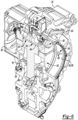
- the housing 24 may have an inlet 29 proximate a top of the housing 24 for receiving lubricant (e.g., oil), which may be distributed over components within the housing 24 and then collected at or near a bottom portion of the housing 24.
- the housing 24 may have various passages and openings machined or otherwise formed therein for routing lubricant to desired locations within the housing 24, as explained below in more detail.
- the lubricant may exit the housing 24 through one or more outlets 30 and then be routed through a cooling and filtration assembly 31 (shown in Figure 3 ), which may include a cooling unit and filter, before being returned to the housing 24 through suitable passages or conduits.
- lubricant may flow from the inlet 29 through a main passage 32 to first and second passage arrangements 34 and 36, respectively, that supply lubricant to first and second motor receptacles 38 and 40, respectively, which each receive a motor 22, and to first and second gear train receptacles 42 and 44 respectively, which each at least partially receive a gear train 25.
- the first and second motor receptacles 38 and 40, respectively, are located on first and second opposite sides, respectively, of a housing central wall 46, and the first and second gear train receptacles 42 and 44, respectively, may be at least partially located on opposite sides of the housing central wall 46.
- the second passage arrangement 36 will now be described in more detail, with the understanding that the first passage arrangement 34 may have the same or similar configuration, but with an inverse orientation, or partial inverse orientation, in a longitudinal direction (e.g., a rearwardly extending passage of the second passage arrangement 36 may correspond to a counterpart forwardly extending passage of the first passage arrangement 34).
- the second passage arrangement 36 may include multiple channels or passages formed in housing walls, and multiple openings in the housing walls that allow the passages to provide lubricant to one or both of the motors 22 in the motor receptacles 38 and 40, and one or both of the gear trains 25 in the gear train receptacles 42 and 44.
- the second passage arrangement 36 may include a lateral passage 48 that connects to a Y-shaped longitudinally extending manifold or passage 50.
- the Y-shaped passage 50 feeds a downwardly extending channel or passage 52 that communicates with the second gear train receptacle 44 through multiple openings formed in one or more housing walls.
- the Y-shaped passage 50 extends to another lateral passage 54, which communicates with the second motor receptacle 40 through one or more openings 56 formed in a curved housing wall 58 that at least partially defines the second motor receptacle 40.
- the Y-shaped passage 50 may also feed a V-shaped longitudinally extending passage or manifold 60, which communicates with the first gear train receptacle 42 located on the first side of the housing central wall 46 through one or more openings 62 formed in the housing central wall 46, as shown in Figure 8 .
- the V-shaped manifold 60 may be covered by a plate 64 as shown in Figure 4 .
- each passage arrangement 34, 36 is configured to supply lubricant on both sides of the housing central wall 46.
- each passage arrangement 34, 36 is configured to supply lubricant to one of the motors 22 and to at least a portion of each gear train 25.
- lubricant may be moved through each passage arrangement 34, 36 by pressure and/or gravity to lubricate and/or cool the motors 22 and associated gear trains 25.
- each of the gear trains 25 may include multiple gears that are configured to mesh together to transmit torque from a respective motor 22 to a respective wheel 14.
- each gear train 25 may be capable of running at multiple (e.g., two) speeds, and the gear trains 25 may have the components and capability to shift between gear ratios independent of each other.
- each gear train 25 may include a suitable shift mechanism 72 that is controlled by an electronic control unit, which may be driven by or otherwise in communication with a vehicle control unit (e.g, a computer).
- a vehicle control unit e.g, a computer
- Each of the above mentioned control units may include suitable hardware and/or software, such as one or more processors (e.g., one or more microprocessors, microcontrollers and/or programmable digital signal processors) in communication with, or configured to communicate with, one or more storage devices or media including computer readable program instructions that are executable by the one or more processors so that the control unit may perform particular algorithms represented by the functions and/or operations described herein.
- processors e.g., one or more microprocessors, microcontrollers and/or programmable digital signal processors
- Each control unit may also, or instead, include one or more application specific integrated circuits, programmable gate arrays or programmable array logic, programmable logic devices, or digital signal processors.
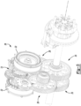
- FIG 9 shows first and second drive systems 28a and 28b, respectively, of a motor gearbox 26, with the housing 24 removed.
- the first drive system 28a includes first motor 22a and associated first gear train 25a
- the second drive system 28b includes second motor 22b and associated second gear train 25b.
- Each drive system 28a, 28b also includes suitable inputs or connections 73a, 73b for receiving electrical power (e.g., from the ESS 18) and/or control signals, and for providing the electrical power and/or control signals to the associated motor 22a, 22b and/or shift mechanisms 72.
- the gear trains 25a and 25b may be positioned at least partially between the motors 22a and 22b.
- the gear trains 25a and 25b are entirely disposed laterally between the motors 22a and 22b.
- staggered dividing line 74 approximately indicates general separation or division of the drive systems 28a and 28b.
- At least portions of the drive systems 28a, 28b may have generally inverse orientations in a longitudinal direction 75 of the truck 10 and with respect to a laterally extending, central plane 76 of the motor gearbox 26.
- at least a portion of one drive system 28a or 28b may have a generally inverse orientation with respect to at least a portion of the other drive system in the longitudinal direction 75 of the truck 10.
- the motors 22a and 22b may have generally inverse orientations with respect to each other in the longitudinal direction 75, and/or portions or all of the gear trains 25a and 25b may have generally inverse orientations with respect to each other in the longitudinal direction 75 (e.g., at least a portion of one gear train 25a may have a generally inverse orientation with respect to at least a corresponding portion of the other gear train 25b in the longitudinal direction 75).
- the motors 22a and 22b are offset with respect to each other in the longitudinal direction 75 and have generally inverse orientations with respect to each other, and multiple gears of the first gear train 25a each have a generally inverse orientation with respect to a corresponding gear of the second gear train 25b.
- motor axis or central axis 77a of motor 22a (e.g., the axis about which the rotor of motor 22a is rotatable) is located forward of central plane 76 by a distance d 1
- motor axis or central axis 77b of motor 22b (e.g., the axis about which the rotor of motor 22b is rotatable) is located rearward of central plane 76 by a distance d 2 .
- an intermediate gear 78a of gear train 25a is located forward of central plane 76, while a corresponding intermediate gear 78b of gear train 25b is located rearward of central plane 76 (e.g., the central plane 76 extends between the intermediate gears 78a and 78b).
- intermediate gear 78a is rotatable about a gear axis 79a that is located forward of the central plane 76 by a distance d 3
- intermediate gear 78b is rotatable about a gear axis 79b that is located rearward of the central plane 76 by a distance d 4 .
- distance d 1 is equal to distance d 2
- distance d 3 is equal to distance d 4
- Output gears 80a and 80b of the gear trains 25a and 25b may be aligned along the central plane 76, and may also be axially aligned so that the corresponding wheels 14 can be axially aligned. Therefore, the output gears 80a and 80b may be aligned with each other, while the other corresponding components of the drive systems 28a and 28b may be offset with respect to each other in the longitudinal direction 75. In some embodiments, corresponding components of the drive systems 28a and 28b may be offset with respect to each other, but spaced relative to the central plane 76 by different distances.
- some corresponding components of the gear trains 25a and 25b may be offset with respect to each other by greater distances in the longitudinal direction 75 than the motors 22a and 22b.
- the central axes 77a and 77b of the motors 22a and 22b are spaced apart by a first distance equal to the sum of d 1 and d 2
- the gear axes 79a and 79b of the intermediate gears 78a and 78b are spaced apart by a second distance equal to the sum of d 3 and d 4 , wherein the second distance is greater than the first distance.
- each drive system 28a and 28b is configured to independently drive a wheel 14 that is located on the same side of the truck 10 as the corresponding motor 22a, 22b when the motor gearbox 26 is mounted on the frame 16 or other portion of the vehicle support structure 17.
- the first drive system 28a is configured to drive a wheel 14 (not shown) positioned proximate motor 22a and to the left of motor 22a
- the second drive system 28b is configured to drive a wheel 14 (not shown) positioned proximate motor 22b and to the right of motor 22b.
- output gear 80a may be connected by a first drive shaft or drive half-shaft (not shown) to a wheel 14 located to the left of the motor 22a
- output gear 80b may be connected by a second drive shaft or drive half-shaft (not shown) to a wheel 14 located to the right of the motor 22b.
- the gear trains 25a and 25b may at least partially overlap each other in a lateral direction 81 of the truck 10 (e.g., at least a portion of the gear train 25a may overlap a least a portion of the gear train 25b) so that the lateral width of the overall motor gearbox 26 may be reduced.
- portions of the gear trains 25a and 25b may occupy a shared volume 82 within the housing 24.
- the intermediate gears 78a and 78b may at least partially laterally overlap each other. In the embodiment shown in Figure 9 , the intermediate gears 78a and 78b fully overlap each other so that they are aligned in the longitudinal direction 75.
- the motor gearbox 26 may have a compact design.
- a motor gearbox 26 according to the disclosure may be positioned at each axle of the truck 10.
- each gear train 25 and associated output wheel 14 can run at multiple (e.g., two) gear ratios.
- the output gear ratio for each drive wheel 14 can effectively be shifted independently of all other wheels 14.
- Figure 10 shows the first drive system 28a operating in a low gear mode or low gear ratio mode with arrows indicating direction of rotation of the rotor of the motor 22a and gears of the gear train 25a
- Figure 11 shows drive system 28a operating in a high gear mode or high gear ratio mode with arrows indicating direction of rotation of the rotor of the motor 22a and gears of the gear train 25a.
- the rotor of the motor 22a may also be rotated in an opposite direction to that shown in Figures 10 and 11 to thereby cause gears of the gear train 25a to rotate in opposite directions compared to the directions shown in Figures 10 and 11 .
- the gear train 25a may include a suitable shift mechanism 72 for shifting the gear train 25a between the gear ratio modes.
- the shift mechanism 72 may include a barrel cam 83 that is actuated by a rotary or linear actuator that may be located at least partially external to the motor gearbox 26 and controlled by the above-mentioned electronic control unit.
- the barrel cam 83 may be rotated or otherwise moved to cause one or more shift selector forks 84 to move linearly and thereby cause one or more dog gears 85, 86 to engage or disengage adjacent gears in order to shift the gear train 25a between the gear ratio modes.
- the dog gear 85 is in an engaged condition and the dog gear 86 is in a disengaged condition. Furthermore, in the low gear ratio mode, rotation of the rotor of motor 22a in a first direction causes input gear 87 to likewise rotate in the first direction, and the input gear 87 engages (e.g., meshes with) first intermediate or driven gear 88 and causes the first driven gear 88 to rotate in a second direction opposite the first direction. Because the dog gear 85 is in the engaged condition, the first driven gear 88 causes second intermediate or driven gear 89 to likewise rotate in the second direction.
- the second driven gear 89 engages (e.g., meshes with) third intermediate or driven gear 90 and causes the third driven gear 90 to rotate in the first direction
- the third driven gear 90 engages (e.g., meshes with) the intermediate gear 78a (which may also be referred to as a driven gear, e.g., fourth driven gear) and causes the intermediate gear 78a to rotate in the second direction.
- the intermediate gear 78a is coupled to a fifth intermediate or driven gear 91 such that rotation of the intermediate gear 78a in the second direction causes the fifth driven gear 91 to also rotate in the second direction.
- the fifth driven gear 91 engages (e.g., meshes with) the output gear 80a and causes the output gear to rotate in the first direction.
- the dog gear 85 is in a disengaged condition and the dog gear 86 is in an engaged condition. Furthermore, in the high gear ratio mode, rotation of the rotor of motor 22a in the first direction causes the input gear 87 to likewise rotate in the first direction. Because the dog gear 86 is in the engaged condition, the input gear 87 causes sixth intermediate or driven gear 92 to likewise rotate in the first direction.
- the sixth driven gear 92 engages (e.g., meshes with) the intermediate gear 78a (e.g., fourth driven gear) and causes the intermediate gear 78a to rotate in the second direction.
- the intermediate gear 78a causes the fifth driven gear 91 to also rotate in the second direction as explained above, and the fifth driven gear 91 engages (e.g., meshes with) the output gear 80a and causes the output gear to rotate in the first direction.
- vehicle shifting events can be staggered among the independent gear trains around the vehicle. For example, where there are three motor gearboxes 26 (one per axle) and six independent motors 22 (one per output wheel 14 or dual wheel pair), the staggered shifting would allow one of these six gear trains 25 to be shifted at a time and then sequentially through the other gear trains. This means that instead of a total loss of power during shifting, there would only be a 1/6th reduction in power at any given time during the shift event. As a result, there is constant power, although slightly reduced, as the truck 10 shifts. Furthermore, with the above configuration, a shifting event can be controlled to be efficient and smooth, without the driver feeling it happen.
- Vehicle electronic stability control may also be performed by braking or reducing power to wheels 14 to prevent slipping and improve traction.
- ECS Vehicle electronic stability control
- Independent motor 22 to wheel 14 coupling as a result of this design also allows independent regenerative braking or deceleration of the wheels 14.
- the motor gearboxes 26 could be controlled to provide regenerative braking and deceleration at or near the friction limit of the tires of the truck 10. This may be possible by using wheel speed and direction sensors that are embedded in each motor gearbox 26 and sense the speed and/or direction of a gear in each gear train 25 that is directly coupled to a particular wheel 14.
- each drive system 28a, 28b of a motor gearbox 26 may include a primary gear speed and direction sensor 93 positioned proximate the associated intermediate gear 78a, 78b (e.g., proximate an outer circumference of the intermediate gear and oriented generally transverse to the associated axis), as well as a secondary gear speed sensor 94 that may be positioned on a side of the associated intermediate gear 78a, 78b.
- the truck 10 further includes front independent suspension systems 95 designed around the front motor gearbox 26 and drive half-shafts intended to drive the front wheels 14 of the vehicle 10.
- Typical Class 8 trucks do not have front wheel drive, so a unique design was developed to allow driving, steering and independent suspension.
- the front suspension systems 95 may be designed to accommodate an air brake system (e.g., air disc brake system) that is used for braking the front wheels 14.
- the front suspension system 95 for one of the front wheels 14 is shown in Figures 12-13B , with the understanding that the truck 10 may include the same or similar front suspension at the other front wheel 14.
- adding front wheel drive capability adds complexity due to the number of moving components vying for the same space near the front wheel 14.
- Such components may include air brake system components (e.g., an air brake chamber 96 and brake caliper assembly 97 that is actuated by the air brake chamber 96), a steering arm or link 98 of a steering system for steering the front wheel, front suspension system components (e.g., upper and lower independent suspension control arms 99 and 100, respectively) and a drive half-shaft 102 and corresponding constant velocity (CV) joint, for example.
- air brake system components e.g., an air brake chamber 96 and brake caliper assembly 97 that is actuated by the air brake chamber 96
- a steering arm or link 98 of a steering system for steering the front wheel e.g., upper and lower independent suspension control arms 99 and 100, respectively
- CV constant velocity
- a custom front support member or knuckle 104 was developed for the front suspension system 95.
- the knuckle 104 rotatably supports the front wheel 14 and associated hub, and may serve as a direct or indirect connection or support area for various components (e.g., the knuckle 104 may be configured to support various components).
- the steering arm 98 may be pivotally connected to the knuckle 104 in any suitable manner, such as with a knuckle mount that includes a pivot member (e.g., pivot ball) and a pivot bearing (e.g., pivot socket).
- control arms 99 and 100 of the front suspension system 95 may each be pivotably connected to the knuckle 104 in any suitable manner, such as with knuckle mounts that each include a pivot member (e.g., pivot ball) and a pivot bearing (e.g., pivot socket).
- the air brake chamber 96 may be mounted on the knuckle 104 or on the brake caliper assembly 97, which may be mounted on the knuckle 104.
- the air brake chamber 96 may be mounted rearward of a center (e.g., rotation axis 105) of the front wheel 14 and associated hub, and proximate or outwardly of an outer circumference of the front wheel 14, to avoid contact with the drive half-shaft 102 and CV boot 106 (which covers the CV joint), steering arm 98, and suspension control arms 99 and 100 during all steering and suspension operational situations (e.g., through full suspension travel and full steering travel of the front wheel 14).
- a center e.g., rotation axis 105
- CV boot 106 which covers the CV joint
- steering arm 98 which covers the CV joint
- suspension control arms 99 and 100 during all steering and suspension operational situations (e.g., through full suspension travel and full steering travel of the front wheel 14).
- the air brake chamber 96 may also be mounted above the rotation axis 105 of the front wheel 14 and associated hub. Likewise, the air brake chamber 96 may be mounted rearward of a vertical plane 107 that passes through the rotation axis 105 and a top portion of the front wheel 14, such that the air brake chamber 96 is mounted rearward of a top-center of the front wheel 14. For example, the air brake chamber 96 may be mounted rearward of the vertical plane 107 such that a center point of the air brake chamber 96 is positioned at an angle in the range 10° to 90° (more particularly 30° to 75°) relative to the vertical plane 107 and axis 105.
- the front suspension system 95 further includes a unique support member or yoke mount 108 for attaching a suspension device, such as a gas (e.g., air) spring and damper assembly 109, to the lower control arm 100.
- a suspension device such as a gas (e.g., air) spring and damper assembly 109
- the spring and damper assembly or spring-damper assembly 109 may include a gas spring 110 (e.g., air spring) and a damper 112 axially aligned with and positioned beneath the gas spring 110.
- the yoke mount 108 includes first and second legs 113 and 114, respectively, that are configured to receive the drive half-shaft 102 therebetween so that the spring-damper assembly 109 may be positioned over the drive half-shaft 102 (e.g., axis of the drive half-shaft 102).
- the drive half-shaft 102 e.g., axis of the drive half-shaft 102
- the drive half-shaft 102 may be aligned with a yoke mount axis and spring-damper assembly axis in order to keep the drive half-shaft 102 and spring-damper assembly 109 in their ideal alignment, as shown in Figure 13B .
- first leg 113 of the yoke mount 108 may also be configured to extend between the drive half-shaft 102 and the steering arm 98. While the yoke mount 108 may be connected to the spring-damper assembly 109 in any suitable manner, in the embodiment shown in Figures 13A and 13B , the first and second legs 113 and 114 are fixedly connected to the spring-damper assembly 109 at first and second spaced apart locations, respectively. Furthermore, the spring 110 may be connected to the frame 16 or other portion of the vehicle support structure 17 (e.g., subframe or suspension cradle).
- vehicle support structure 17 e.g., subframe or suspension cradle
- the above-mentioned suspension device may be any suitable suspension device, such as a linear or non-linear dynamic suspension member.
- the suspension device may include a coil spring, a magnetic suspension member and/or an electromagnetic suspension member.
- the front suspension systems 95 are also configured to fit around the front motor gearbox 26, which is centered within the suspension cradle. This makes it possible to have independent front suspensions while also being able to directly drive left and right front wheels 14 independently using the electric dual motor gearbox 26 located in between the front wheels 14.
- inboard ends of the control arms 99, 100 may be pivotally connected to the vehicle support structure 17 (e.g., suspension cradle or frame 16) proximate the motor gearbox 26 and the center of the truck 10.
- the housing 24 of the front motor gearbox 26 may be connected to at least one of the control arms 99 and 100 of one or both of the front suspension systems 95.
- front motor gearbox 26' includes an enlarged housing 24' to which the control arms 99 and 100 of right and left front suspension systems 95 are connected.
- each of the right and left sides of an upper portion of the housing 24' has two upper, laterally projecting portions 116 to which a particular upper control arm 99 is pivotally connected.
- the housing 24' includes an enlarged lower portion 118, and each of the right and left sides of the lower portion 118 has two lower, laterally projecting portions 120 to which a particular lower control arm 100 is pivotally connected.
- the housing 24' may be connected to vehicle support structure 17' (e.g., front suspension cradle or frame 16) and may be made of a suitable material, such as metal (e.g, aluminum), carbon-reinforced plastic or other composite material, etc., so that the housing 24' may support the above components. With such a configuration, portions of the front suspension cradle may be omitted, so that the overall vehicle weight may be reduced.
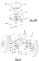
- the front suspension cradle may be integrally formed with the housing 24' (e.g., molded together), as shown in Figure 14 , to further reduce vehicle weight, or the suspension cradle may be formed separately from the housing 24' and attached to the housing 24'.
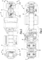
- the truck 10 further includes rear independent suspension systems 122 and associated cradles that are configured to provide independent suspension at each rear wheel 14, while also allowing direct independent driving of the rear wheels 14 using a dual motor gearbox 26 located between the wheels 14 at each of two rear axle locations.
- the rear suspension systems 122 may also be configured to enable accurate alignment (e.g., coaxial alignment) of drive half-shafts 102r connected to each rear motor gearbox 26, so that the output gears 80 of each rear motor gearbox 26 may be coaxially aligned with corresponding rear wheels 14 when the drive half-shafts 102r are positioned in a horizontal orientation. With such a configuration, the rear suspension systems 122 may provide improved suspension travel and feel.
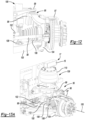
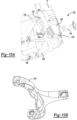
- the rear suspension system 122 for one of the rear wheels 14 is shown in Figures 15A-16 , with the understanding that the truck 10 may include the same or similar rear suspension at each rear wheel 14.
- the rear suspension system 122 includes upper and lower control arms 124 and 126, respectively, that may be configured to have inboard pivot points or axes located as close to the center of the truck 10 as possible (around an associated motor gearbox 26) to allow the most accurate suspension travel from full jounce to rebound (i.e., full up and down movement).
- the control arms 124 and 126 may also be configured to have outboard pivot points or axes as close to an associated rear tire as possible.
- each suspension device may comprise any suitable suspension device, such as a linear or non-linear dynamic suspension member.
- each suspension device may comprise a coil spring, a magnetic suspension member and/or an electromagnetic suspension member.
- the upper control arm 124 includes a first or inboard portion having two arms, and a second or outboard portion formed as a single arm. Inboard ends of the upper control arm 124 are each pivotally attached to the vehicle support structure 17 (e.g., suspension cradle or frame 16), such as with a cradle mount 132 (e.g., pivot member or rod and pivot bearing), at a location around the exterior of the motor gearbox 26 and proximate the center of the truck 10.
- the outboard portion of the upper control arm 124 may pass between two air springs 128 and/or between the associated upright axes 130 of the air springs 128.
- the outboard portion of the upper control arm 124 is centered between the upright axes 130 of the air springs 128.
- the outboard portion of the upper control arm 124 extends into an opening 134 in a rear support member or knuckle 136, to which the two air springs 128 are mounted.
- the outboard portion further includes a single wheel side end or outboard end that may be pivotally connected to the knuckle 136, such as with a knuckle mount 138 (e.g., pivot member or rod and pivot bearing), at a location proximate an outboard side of the knuckle 136 (e.g., as close to a corresponding rear wheel as possible).
- a knuckle mount 138 e.g., pivot member or rod and pivot bearing
- the outboard end of the upper control arm 124 is pivotally connected to an outboard face of the knuckle 136.
- the outboard end of the upper control arm 124 may be pivotally connected to the knuckle 136 with a knuckle mount 138 including a pivot member, such as a pivot rod, that is fixedly received in a channel or notch formed in the outboard face of the knuckle 136 and about which the upper control arm 124 is pivotable.
- the lower control arm 126 includes an inboard portion having two inboard ends that are each pivotally attached to the vehicle support structure 17 (e.g., suspension cradle or frame 16), such as with a cradle mount 140 (e.g., pivot member or rod and pivot bearing), at a location beneath the motor gearbox 26.
- the cradle mounts 140 of the lower control arm 126 are located closer to the center of the truck 10 than the cradle mounts 132 of the upper control arm 124. Such a configuration may provide improved suspension response, while also providing improved suspension travel.
- the knuckle 136 is also configured to rotatably support a rear wheel 14 (e.g., dual wheel pair).
- the knuckle 136 may be attached to a wheel spindle 144 that supports a rear wheel 14 (e.g., the wheel spindle 144 may be attached to a hub on which the rear wheel 14 is mounted).
- the configuration of the knuckle 136 enables two air springs 128, or other suspension devices, to be mounted to a top of the knuckle (e.g., the upper portion 145) and further allows the second portion of the upper control arm 124 to pass through a majority or all of the knuckle 136 to the outside or outboard face of the knuckle 136.
- the second portion of the upper control arm 124 may be aligned with a central vertical axis of the knuckle 136 and an axis of the wheel 14 and associated hub.
- the rear suspension system 122 may further include one or more shock absorbers or dampers 150 connected between the lower control arm 126 and the vehicle support structure 17, such as the suspension cradle or frame 16.
- the damper 150 is positioned rearward of the air springs 128 and knuckle 136.
- the rear suspension system 122 may handle significant loads, while maintaining a low profile.
- the air springs 128 may cooperate to effectively handle large loads, yet each air spring 128 may be sized to fit between the frame rail of the frame 16 and an associated rear tire.
- the upper control arm 124 and knuckle 136 may cooperate to keep loads centered on the associated rear drive half-shaft 102r.
- connection locations (e.g., pivot point or pivot axis locations) of the outboard portions of the control arms 124 and 126 with the knuckle 136 may be generally vertically aligned with each other, when viewed in the longitudinal direction 75 of the truck 10. In other words, connection locations of the outboard portions of the control arms 124 and 126 with the knuckle 136 may fall generally within a vertical plane 154 that is oriented in the longitudinal direction 75 of the truck 10.
- the outboard side mount 138 of the upper control arm 124 may be vertically aligned with the outboard side mounts 142 of the lower control arm 126, when viewed in the longitudinal direction 75, such that the outboard side mount 138 of the upper control arm 124 and the outboard side mounts 142 of the lower control arm 126 are located in the vertical plane 154.
- the tire 152 and associated wheel 14 may be able to maintain close to a vertical orientation with respect to a road surface through the full travel range of the rear suspension system 122.
- the rear suspension system 122 may provide improved tracking of the tire 152.
- Figure 18 shows the inboard portions or ends of the upper and lower control arms 124 and 126, respectively, pivotally connected to the vehicle support structure 17 (e.g., suspension cradle or frame 16) proximate the center of the truck 10 and motor gearbox 26.
- vehicle support structure 17 e.g., suspension cradle or frame 16
- inboard portions or ends of one or both of the control arms 124 and 126 of each rear suspension system 122 for a particular rear axle may be pivotally connected to the housing 24 of the associated motor gearbox 26.
- motor gearbox 26" includes an enlarged housing 24" to which the control arms 124 and 126 of aligned rear suspension systems 122 are connected.
- each of the right and left sides of an upper portion of the housing 24" has two upper, laterally projecting portions 156 to which a particular upper control arm 124 is pivotally connected.
- the housing 24" includes an elongated lower portion 158 to which the lower control arms 126 are pivotally connected.
- the housing 24" may be connected to vehicle support structure 17" (e.g., suspension cradle or frame 16) and may be made of a suitable material, such as metal (e.g, aluminum), carbon-reinforced plastic or other composite material, etc., so that the housing 24" may support the above components. With such a configuration, portions of the suspension cradle may be omitted, so that the overall vehicle weight may be reduced.
- the suspension cradle may be integrally formed with the housing 24" (e.g., molded together) to further reduce vehicle weight, or the suspension cradle may be formed separately from the housing 24" and attached to the housing 24".
Landscapes
- Engineering & Computer Science (AREA)
- Mechanical Engineering (AREA)
- Chemical & Material Sciences (AREA)
- Combustion & Propulsion (AREA)
- Transportation (AREA)
- General Engineering & Computer Science (AREA)
- Arrangement Or Mounting Of Propulsion Units For Vehicles (AREA)
- Body Structure For Vehicles (AREA)
- Vehicle Body Suspensions (AREA)
- Gear Transmission (AREA)
- General Details Of Gearings (AREA)
- Connection Of Motors, Electrical Generators, Mechanical Devices, And The Like (AREA)
Claims (15)
- Fahrzeug (10) mit:einer Fahrzeugtragstruktur (17);einem ersten und einem zweiten Hinterrad (14), die jeweils in Bezug auf die Fahrzeugtragstruktur (17) drehbar sind;einem ersten und einem zweiten unabhängigen Hinterradaufhängungssystem (122), die jeweils dem ersten und dem zweiten Hinterrad (14) zugeordnet sind;dadurch gekennzeichnet, dass das Fahrzeug (10) ferner eine Doppelmotor-Getriebe-Baugruppe (26) umfasst, die zwei unabhängige Elektromotoren (22) zum Antreiben jeweils eines der Hinterräder (14), zugehörige Getriebezüge (25) für die Motoren (22) und ein Gehäuse (24; 24'), das die Motoren (22) und die Getriebezüge (25) aufnimmt, umfasst;wobei jedes Hinterradaufhängungssystem (122) umfasst:einen Achsschenkel (136), der eines der Hinterräder (14) trägt, wobei der Achsschenkel (136) eine Öffnung definiert, die sich seitlich durch den Achsschenkel (136) erstreckt;zwei Aufhängungsvorrichtungen (128), die mit der Fahrzeugtragstruktur (17) und einem oberen Abschnitt des Achsschenkels (136) verbunden sind, so dass jede Aufhängungsvorrichtung (128) entlang einer aufrechten Achse ausgerichtet ist; undeinen oberen Steuerarm (124) mit einem von der Fahrzeugtragstruktur (17) getragenen ersten Abschnitt und einem zweiten Abschnitt, der sich zwischen den Achsen der Aufhängungsvorrichtungen (128) und direkt in die Öffnung des Achsschenkels (136) erstreckt, wobei der zweite Abschnitt des Steuerarms (124) schwenkbar mit einer seitlich orientierten Außenfläche des Achsschenkels (104; 136) verbunden ist.
- Fahrzeug nach Anspruch 1, bei dem jede Aufhängungsvorrichtung (128) ein Gasfederelement (109) umfasst.
- Fahrzeug nach Anspruch 2, bei dem jedes Gasfederelement (109) eine Luftdruckfeder (110) umfasst.
- Fahrzeug (10) nach Anspruch 1, bei dem für jedes Hinterradaufhängungssystem der zweite Abschnitt des Steuerarms (124) sich zwischen den Aufhängungsvorrichtungen (128) erstreckt.
- Fahrzeug (10) nach Anspruch 1, bei dem das Gehäuse (24; 24') der Motor-Getriebe-Baugruppe (26) mit der Fahrzeugtragstruktur (17) verbunden ist und der erste Abschnitt des Steuerarms (124) jedes Hinterradaufhängungssystems mit dem Gehäuse (24; 24') verbunden ist.
- Fahrzeug (10) nach Anspruch 1, bei dem für jedes Hinterradaufhängungssystem der zweite Abschnitt des Steuerarms (124) über ein Schwenkelement (132) mit dem Achsschenkel (136) verbunden ist.
- Fahrzeug (10) nach Anspruch 6, bei dem für jedes Hinterradaufhängungssystem der Achsschenkel (136) eine in der Außenfläche ausgebildete Kerbe aufweist und die Kerbe das Schwenkelement (132) aufnimmt.
- Fahrzeug (10) nach Anspruch 1, bei dem der Steuerarm (124) jedes Hinterradaufhängungssystems ein oberer Steuerarm (124) ist und jedes Hinterradaufhängungssystem ferner einen unteren Steuerarm (126) mit einem von der Fahrzeugtragstruktur (17) getragenen ersten Abschnitt und einem mit einem unteren Ende des Achsschenkels (104; 136) verbundenen zweiten Abschnitt umfasst, so dass bei jedem Hinterradaufhängungssystem die Verbindungsstellen der zweiten Abschnitte der Steuerarme (124; 126) mit dem Achsschenkel (104; 136) in Längsrichtung (75) des Fahrzeugs (10) betrachtet im Allgemeinen vertikal zueinander ausgerichtet sind und in der Nähe eines am Hinterrad (14) montierten Reifens (152) positioniert sind.
- Fahrzeug (10) nach Anspruch 8, bei dem für jedes Hinterradaufhängungssystem der untere und/oder der obere Steuerarm (124; 126) an dem Gehäuse (24; 24') angebracht ist/sind.
- Fahrzeug (10) nach Anspruch 8, das ferner für jedes Hinterradaufhängungssystem ein Dämpfungselement (112) umfasst, das mit dem unteren Steuerarm (126) und der Fahrzeugtragstruktur (17) verbunden ist.
- Fahrzeug (10) nach Anspruch 1, bei dem für jedes Hinterradaufhängungssystem der Steuerarm (124) an dem Gehäuse (24; 24') angebracht ist.
- Fahrzeug (10) nach Anspruch 1, bei dem für jedes Hinterradaufhängungssystem der zweite Abschnitt des Steuerarms (124) über ein vom Steuerarm getrenntes Befestigungselement (108) schwenkbar mit dem Achsschenkel (104; 136) verbunden ist.
- Fahrzeug (10) nach Anspruch 1, bei dem für jedes Hinterradaufhängungssystem der Achsschenkel (136) mehrere miteinander verbundene Teile umfasst.
- Fahrzeug (10) nach Anspruch 1, bei dem die zwei Elektromotoren (22) und die zugehörigen Getriebezüge (25) von dem Gehäuse (24; 24') umschlossen sind.
- Fahrzeug (10) nach Anspruch 14, bei dem die Elektromotoren (22) in Längsrichtung (75) des Fahrzeugs (10) gegeneinander versetzt sind.
Applications Claiming Priority (4)
| Application Number | Priority Date | Filing Date | Title |
|---|---|---|---|
| US201662391745P | 2016-05-09 | 2016-05-09 | |
| US15/357,350 US10207751B2 (en) | 2016-05-09 | 2016-11-21 | Motor gearbox assembly |
| US15/366,472 US10336379B2 (en) | 2016-05-09 | 2016-12-01 | Vehicle rear suspension system |
| PCT/US2017/031653 WO2017196778A1 (en) | 2016-05-09 | 2017-05-09 | Vehicle rear suspension system |
Publications (3)
| Publication Number | Publication Date |
|---|---|
| EP3455093A1 EP3455093A1 (de) | 2019-03-20 |
| EP3455093A4 EP3455093A4 (de) | 2020-01-01 |
| EP3455093B1 true EP3455093B1 (de) | 2024-10-16 |
Family
ID=60242501
Family Applications (2)
| Application Number | Title | Priority Date | Filing Date |
|---|---|---|---|
| EP17796591.0A Active EP3455096B1 (de) | 2016-05-09 | 2017-05-04 | Motorgetriebeanordnung |
| EP17796652.0A Active EP3455093B1 (de) | 2016-05-09 | 2017-05-09 | Fahrzeug mit einem hinterradaufhängungssystem |
Family Applications Before (1)
| Application Number | Title | Priority Date | Filing Date |
|---|---|---|---|
| EP17796591.0A Active EP3455096B1 (de) | 2016-05-09 | 2017-05-04 | Motorgetriebeanordnung |
Country Status (8)
| Country | Link |
|---|---|
| US (7) | US10207751B2 (de) |
| EP (2) | EP3455096B1 (de) |
| JP (2) | JP7253383B2 (de) |
| KR (2) | KR102351557B1 (de) |
| AU (3) | AU2017262563A1 (de) |
| CA (3) | CA3023437C (de) |
| MX (3) | MX2018013506A (de) |
| WO (4) | WO2017196633A1 (de) |
Families Citing this family (60)
| Publication number | Priority date | Publication date | Assignee | Title |
|---|---|---|---|---|
| US20140175782A1 (en) | 2012-10-19 | 2014-06-26 | Agility Fuel Systems, Inc. | Systems and methods for mounting a fuel system |
| US10207751B2 (en) | 2016-05-09 | 2019-02-19 | Nikola Motor Company Llc | Motor gearbox assembly |
| US10981609B2 (en) * | 2015-12-30 | 2021-04-20 | Nikola Corporation | Systems, methods, and devices for an automobile door or window |
| US11001129B2 (en) | 2015-12-30 | 2021-05-11 | Nikola Corporation | Cargo door for semi-truck |
| US10435075B2 (en) | 2016-05-06 | 2019-10-08 | Arvinmeritor Technology, Llc | Suspension module having a subframe assembly |
| US10266025B2 (en) | 2016-05-06 | 2019-04-23 | Arvinmeritor Technology, Llc | Suspension module having an air spring pedestal |
| USD832745S1 (en) * | 2016-09-19 | 2018-11-06 | Iveco S.P.A. | Vehicle |
| USD826098S1 (en) * | 2016-09-19 | 2018-08-21 | Iveco S.P.A. | Vehicle |
| US10527130B2 (en) * | 2016-09-30 | 2020-01-07 | Grant Shirley | Gear lift box assembly |
| US10703178B2 (en) * | 2016-11-07 | 2020-07-07 | Ford Global Technologies, Llc | Windshield wrapped vehicle pillar |
| CN108263205B (zh) * | 2016-12-30 | 2020-02-07 | 比亚迪股份有限公司 | 锁止装置、动力总成、动力传动系统及车辆 |
| DE102018202950A1 (de) * | 2017-03-06 | 2018-10-25 | Nabtesco Corporation | Drehzahlminderer, antriebsrad und wagen |
| USD826817S1 (en) * | 2017-04-10 | 2018-08-28 | Volvo Lastvagnar Ab | Body part for vehicle |
| US10272899B2 (en) * | 2017-08-01 | 2019-04-30 | Proterra Inc. | Controlling the powertrain of a vehicle |
| EP3667876B1 (de) * | 2017-11-17 | 2022-11-23 | Aisin Corporation | Fahrzeugantriebsvorrichtung |
| EP3539810A1 (de) * | 2018-03-13 | 2019-09-18 | FCA Italy S.p.A. | Elektrofahrzeug mit modularem aufbau |
| DE202018103672U1 (de) * | 2018-06-27 | 2019-09-30 | Hofer-Pdc Gmbh | Bauraumanordnung eines Kfz-Antriebsstrangs, insbesondere mit zwei Elektromotoren |
| WO2020041630A1 (en) | 2018-08-24 | 2020-02-27 | Hexagon Purus North America Holdings Inc. | Battery system for heavy duty vehicles |
| US10787073B2 (en) * | 2018-12-11 | 2020-09-29 | Ford Global Technologies, Llc | Electric drive unit for vehicle with clockable gearbox |
| IT201800021025A1 (it) * | 2018-12-24 | 2020-06-24 | Fpt Ind Spa | Sistema di trazione elettrica modulare |
| US10589788B1 (en) | 2019-01-29 | 2020-03-17 | Nikola Motor Company Llc | Vehicle frame arrangement |
| US10926596B2 (en) | 2019-02-28 | 2021-02-23 | Arvinmeritor Technology, Llc | Suspension system |
| US10913321B2 (en) * | 2019-03-04 | 2021-02-09 | Arvinmeritor Technology, Llc | Suspension system |
| US10814917B2 (en) | 2019-03-04 | 2020-10-27 | Arvinmeritor Technology, Llc | Assembly having a skid plate module |
| EP3956163A4 (de) | 2019-04-19 | 2023-01-18 | Hexagon Purus North America Holdings Inc. | Montage von elektrischen frontend-zubehörteilen |
| MX2021012601A (es) | 2019-04-19 | 2022-01-18 | Hexagon Purus North America Holdings Inc | Sistema de motopropulsion eléctrico para vehículos pesados. |
| US12195119B2 (en) * | 2019-09-14 | 2025-01-14 | Robby Gordon | Modular front drivetrain assembly |
| US11958535B2 (en) * | 2019-09-14 | 2024-04-16 | Robby Gordon | Modular front drivetrain assembly |
| EP4011719B1 (de) * | 2019-11-14 | 2024-10-30 | Aisin Corporation | Fahrzeugantriebsvorrichtung |
| CA3161967C (en) | 2019-11-26 | 2025-05-13 | Hexagon Purus North America Holdings Inc. | POWER DISTRIBUTION FOR ELECTRIC VEHICLES AND MOTOR CONTROL MODULE |
| DE202019107168U1 (de) * | 2019-12-20 | 2021-03-23 | Spicer Gelenkwellenbau Gmbh | Antriebsstrang für ein Fahrzeug |
| CN110979149B (zh) * | 2019-12-31 | 2021-04-23 | 长沙凯瑞重工机械有限公司 | 一种动力系统及应用该动力系统的抱罐车 |
| JP7348092B2 (ja) * | 2020-01-27 | 2023-09-20 | ダイムラー トラック エージー | 電動トラック用の駆動装置 |
| JP7348093B2 (ja) | 2020-01-27 | 2023-09-20 | ダイムラー トラック エージー | 電動トラック用の駆動装置 |
| JP7283406B2 (ja) * | 2020-01-31 | 2023-05-30 | トヨタ自動車株式会社 | 車両 |
| CN115176077A (zh) * | 2020-02-26 | 2022-10-11 | 清焰发动机公司 | 燃料不可知的压燃式发动机 |
| WO2021175560A1 (en) * | 2020-03-03 | 2021-09-10 | Volvo Truck Corporation | Vehicle with crash impact absorbing arrangement |
| IT202000006940A1 (it) | 2020-04-02 | 2021-10-02 | Brist Axle Systems S R L | Sospensione indipendente |
| CN111660724A (zh) * | 2020-06-10 | 2020-09-15 | 安徽爱瑞特新能源专用汽车股份有限公司 | 一种无人驾驶扫地车用前桥减震装置 |
| US11926207B2 (en) | 2020-10-09 | 2024-03-12 | Hexagon Purus North America Holdings Inc. | Battery and auxiliary components for vehicle trailer |
| CA3205080A1 (en) | 2020-12-11 | 2022-06-16 | Hexagon Purus North America Holdings Inc. | Trailer hookup breakaway mitigation systems and methods |
| CN112477686A (zh) | 2020-12-15 | 2021-03-12 | 浙江吉利控股集团有限公司 | 一种无中间传动轴的换电式运载车辆 |
| DE102022100114A1 (de) * | 2021-01-05 | 2022-07-07 | Dana Heavy Vehicle Systems Group, Llc | Kabinenisolationssystem |
| GB202102372D0 (en) * | 2021-02-19 | 2021-04-07 | Hughes Thomas | Independent electric drive for low floor vehicles |
| US11371588B1 (en) * | 2021-02-22 | 2022-06-28 | Arvinmeritor Technology, Llc | Axle assembly having a barrel cam |
| US20220297779A1 (en) * | 2021-03-22 | 2022-09-22 | Robby Gordon | Front structural bulkhead for vehicle chassis |
| US11807056B2 (en) * | 2021-04-16 | 2023-11-07 | Rivian Ip Holdings, Llc | Break-away tow hook |
| US12559175B1 (en) | 2021-05-12 | 2026-02-24 | Jason M. Klein | Combination front axle/turntable with independent electric driven wheel ends |
| EP4180256A1 (de) * | 2021-11-10 | 2023-05-17 | Blue Technologies BV | Automobil und verfahren zum betreiben eines automobils |
| EP4426574A4 (de) * | 2021-12-03 | 2026-01-21 | Omni Powertrain Tech Llc | Zweiganggetriebe |
| WO2023211528A1 (en) * | 2022-02-10 | 2023-11-02 | Robby Gordon | Modular front drivetrain assembly |
| US12320417B2 (en) | 2022-03-08 | 2025-06-03 | Fca Us Llc | Vehicle electric drive module with thermal management system |
| USD1042271S1 (en) * | 2022-11-30 | 2024-09-17 | Hyzon Motors USA Inc. | Semi-truck front windshield |
| USD1107068S1 (en) * | 2024-06-04 | 2025-12-23 | Ningbo Science Full Motor Company Limited | Geared motor |
| USD1107069S1 (en) * | 2024-06-04 | 2025-12-23 | Ningbo Science Full Motor Company Limited | Geared motor |
| USD1107067S1 (en) * | 2024-06-04 | 2025-12-23 | Ningbo Science Full Motor Company Limited | Geared motor |
| USD1118695S1 (en) * | 2024-06-04 | 2026-03-17 | Ningbo Science Full Motor Company Limited | Geared motor |
| USD1115860S1 (en) * | 2024-09-13 | 2026-03-03 | Ningbo Science Full Motor Company Limited | Geared motor |
| USD1114844S1 (en) * | 2024-09-13 | 2026-02-24 | Ningbo Science Full Motor Company Limited | Geared motor |
| USD1114845S1 (en) * | 2024-09-13 | 2026-02-24 | Ningbo Science Full Motor Company Limited | Geared motor |
Family Cites Families (111)
| Publication number | Priority date | Publication date | Assignee | Title |
|---|---|---|---|---|
| US2626180A (en) * | 1950-07-05 | 1953-01-20 | Jackie L Thompson | Automotive vehicle body construction |
| US2866651A (en) | 1956-06-29 | 1958-12-30 | Charles L Powell | Vehicle wheel suspension means |
| DE1057469B (de) | 1956-09-19 | 1959-05-14 | Daimler Benz Ag | Luftfederung, insbesondere fuer Schwerlast-kraftwagen od. dgl. |
| US2971772A (en) | 1959-03-18 | 1961-02-14 | Fruehauf Trailer Co | Wheel suspension and cantilever spring bracing therefor for trailer |
| US3007716A (en) | 1960-08-18 | 1961-11-07 | Youngstown Steel Car Corp | Air cell supported road vehicle frame |
| US3477738A (en) | 1968-01-16 | 1969-11-11 | Gen Motors Corp | Auxiliary road wheel assembly |
| US3770312A (en) * | 1971-12-23 | 1973-11-06 | Sparton Management Services In | Pickup truck cab with retractable or removable rear window |
| US4174855A (en) | 1977-01-13 | 1979-11-20 | Turner Quick-Lift Corporation | Wheeled vehicle axle suspension system |
| USD254060S (en) * | 1977-11-10 | 1980-01-29 | Charlene Spellins | Truck cab |
| JPS54131210A (en) | 1978-04-03 | 1979-10-12 | Kawasaki Heavy Ind Ltd | Device for suspending guide track car |
| DE2918605A1 (de) | 1979-05-09 | 1980-11-13 | Daimler Benz Ag | Einzelradaufhaengung mittels uebereinander angeordneter fuehrungslenker |
| DE3136305A1 (de) | 1981-09-12 | 1983-03-24 | Hermann Dr.-Ing. 7412 Eningen Klaue | Antriebsachse fuer schwere kraftwagen |
| USD291872S (en) * | 1984-12-10 | 1987-09-15 | Paccar Inc. | Cab-over-engine truck cab |
| USD291674S (en) * | 1985-05-21 | 1987-09-01 | Pegasus Truck Cab Conversions, Inc. | Truck cab |
| DE3734212A1 (de) | 1986-12-10 | 1989-04-20 | Sterki Ag | Achse |
| US4813704A (en) | 1988-06-20 | 1989-03-21 | Chrysler Motors Corporation | Dual strut wheel suspension |
| DE68917057T2 (de) * | 1988-08-29 | 1994-11-17 | Suzuki Motor Co | Kraftfahrzeug mit Schiebetüren. |
| US4867468A (en) * | 1988-09-15 | 1989-09-19 | Paccar Inc | Decking technique for delivering a plurality of trucks and for towing generally |
| US4932716A (en) * | 1988-09-15 | 1990-06-12 | Paccar Inc. | Highway truck-tractor |
| JPH02306828A (ja) * | 1989-05-19 | 1990-12-20 | Toyota Central Res & Dev Lab Inc | 自動車用両輪独立駆動装置 |
| JP3196121B2 (ja) * | 1991-11-28 | 2001-08-06 | 株式会社東京アールアンドデー | 電気自動車 |
| US5396968A (en) * | 1992-03-18 | 1995-03-14 | Aisin Aw Co., Ltd. | Drive mechanism for electric car |
| JP3122728B2 (ja) | 1992-04-28 | 2001-01-09 | 本田技研工業株式会社 | 自動車の車輪懸架装置 |
| GB2271384B (en) * | 1992-10-06 | 1996-06-19 | Soley Antonio Codina | Improvements in and relating to sliding doors |
| USD357436S (en) * | 1993-10-28 | 1995-04-18 | Moar John R | Truck tractor |
| US5413462A (en) | 1994-03-08 | 1995-05-09 | Reliance Electric Industrial Co. | Mechanical power transmission system having improved lubricant circulation apparatus |
| DE4421425C1 (de) | 1994-06-18 | 1995-08-10 | Fichtel & Sachs Ag | Elektrisches Antriebsaggregat für ein Fahrzeug |
| NL1000342C2 (nl) | 1995-05-11 | 1996-11-12 | Weweler Nv | Luchtveersysteem. |
| US5833298A (en) * | 1996-03-28 | 1998-11-10 | Min; Aung | Tiltable full vision automobile windshield |
| DE19619321C2 (de) | 1996-05-14 | 1998-07-09 | Voith Turbo Kg | Verfahren zum Betrieb eines Fahrzeugs mit mehreren elektrischen Antriebsmaschinen |
| FR2749223B1 (fr) * | 1996-05-29 | 1998-07-31 | Gec Alsthom Transport Sa | Essieu motorise a roues independantes en rotation |
| FR2752778B1 (fr) | 1996-08-27 | 1998-10-09 | Smh Management Services Ag | Groupe de traction tandem a reducteurs et vehicule a traction electrique ou hybride comportant un tel groupe |
| JPH10324126A (ja) | 1997-05-26 | 1998-12-08 | Isuzu Motors Ltd | 車両用サスペンション装置 |
| AU8071498A (en) | 1997-10-31 | 1999-05-24 | Constant Velocity | Independent rear suspension system |
| NL1008060C2 (nl) | 1998-01-19 | 1999-07-20 | Stichting Platform Hoogwaardig | Voertuig, in het bijzonder een elektrisch aangedreven voertuig. |
| DE19860230A1 (de) | 1998-12-24 | 2000-02-17 | Daimler Chrysler Ag | Mehrachsiges Kraftfahrzeug, insbesondere Nutzfahrzeug |
| JP4093515B2 (ja) * | 1999-05-12 | 2008-06-04 | 本田技研工業株式会社 | 前後輪駆動車両 |
| SE516470C2 (sv) | 1999-09-29 | 2002-01-15 | Scania Cv Ab | Framaxelanordning för ett tungt fordon |
| WO2001051300A1 (en) | 2000-01-11 | 2001-07-19 | Bridgestone/Firestone, Inc. | Pneumatic suspension system for vehicles |
| US6840525B1 (en) | 2000-03-14 | 2005-01-11 | Meritor Heavy Vehicle Systems Limited | Air spring and pedestal |
| US6428027B1 (en) | 2000-05-22 | 2002-08-06 | The Boler Company | Front axle air suspension |
| US6866295B2 (en) | 2000-12-28 | 2005-03-15 | Dana Corporation | Modular cast independent front suspension subframe |
| US6695351B2 (en) | 2001-05-02 | 2004-02-24 | Meritor Heavy Vehicle Technology, Llc | Internal bulkhead for spring seat reinforcement |
| US6659526B2 (en) * | 2001-05-25 | 2003-12-09 | Integrated Vision, Inc. | Canopy and visor windshield for a mobility vehicle |
| US6743135B2 (en) * | 2001-09-28 | 2004-06-01 | General Motors Corporation | Modularly-constructed vehicular transmissions |
| US20030098564A1 (en) | 2001-11-29 | 2003-05-29 | Vandenberg Ervin | Independent suspension system for light and medium duty vehicles |
| US6752410B2 (en) | 2001-12-28 | 2004-06-22 | Meritor Heavy Vehicle Technology, Llc | Independent suspension for low profile vehicles |
| US6698313B2 (en) * | 2002-01-15 | 2004-03-02 | Fairway Golf Cars, Llc | Dual motor gear drive unit |
| US7484744B2 (en) | 2002-02-01 | 2009-02-03 | Saf-Holland, Inc. | Trailing arm suspension with optimized I-beam |
| US6820707B1 (en) * | 2002-06-03 | 2004-11-23 | The Ohio State University Research Foundation | Two motor electric axle |
| US20040150142A1 (en) | 2003-02-05 | 2004-08-05 | Warinner Derek K. | Steering beam axle air spring suspension |
| WO2004106110A1 (en) | 2003-06-03 | 2004-12-09 | Gemco Mobile Systems B.V. | Wheel suspension and vehicle |
| US6886647B1 (en) | 2003-06-17 | 2005-05-03 | Bruce Gotta | Dual motor axle-driven generator system for electric vehicles |
| JP2005104215A (ja) * | 2003-09-29 | 2005-04-21 | Nissan Motor Co Ltd | 車両用駆動装置 |
| JP4489551B2 (ja) * | 2004-09-30 | 2010-06-23 | 本田技研工業株式会社 | 車両のボディー構造 |
| BRPI0405014A (pt) | 2004-11-16 | 2006-06-27 | Jorge Antonio Rodrigues Claro | suspensão para veìculos |
| US7472914B2 (en) | 2005-02-28 | 2009-01-06 | Anderson Brian K | Suspension system |
| US20060208447A1 (en) | 2005-03-21 | 2006-09-21 | Arvinmeritor Technology, Llc | Independent suspension for a drive axle |
| DE102005019489A1 (de) * | 2005-04-27 | 2006-11-09 | Krauss-Maffei Wegmann Gmbh & Co. Kg | Allradangetriebenes Kraftfahrzeug |
| US8029008B2 (en) | 2005-04-27 | 2011-10-04 | Hendrickson Usa, L.L.C. | Vehicle suspensions having leaf springs and alternative clamp groups |
| US7819411B2 (en) | 2005-05-20 | 2010-10-26 | Arvinmeritor Technology, Llc | Six link independent suspension for a drive axle |
| JP4479672B2 (ja) * | 2006-02-15 | 2010-06-09 | 三菱自動車工業株式会社 | モータ付車両のリヤリジットサスペンション装置 |
| US20100025131A1 (en) | 2006-04-03 | 2010-02-04 | Bluwav Systems, Llc | Electric propulsion system |
| US7384357B2 (en) | 2006-05-05 | 2008-06-10 | Ford Global Technologies, Llc | Speed reduction gear train with planetary differential for electric motor axle drive |
| DE102006044151A1 (de) | 2006-09-15 | 2008-03-27 | Thyssenkrupp Automotive Ag | Einzelradaufhängung vom Doppelquerlenker-Typ |
| JP2008183956A (ja) * | 2007-01-29 | 2008-08-14 | Mazda Motor Corp | 車両用駆動装置の配設構造 |
| US7793954B2 (en) | 2007-06-22 | 2010-09-14 | Radar Industries, Inc. | Suspension system for a vehicle |
| US20090014223A1 (en) | 2007-07-09 | 2009-01-15 | Jones Robert M | Differential for a lightweight vehicle |
| US7971890B2 (en) | 2007-07-16 | 2011-07-05 | Reyco Granning, Llc | Independent suspension assembly |
| JP4980825B2 (ja) | 2007-08-28 | 2012-07-18 | 日立オートモティブシステムズ株式会社 | ステアリング装置 |
| JP5117960B2 (ja) * | 2008-08-22 | 2013-01-16 | アイシン・エィ・ダブリュ株式会社 | 車両用駆動装置 |
| US20100117318A1 (en) | 2008-11-12 | 2010-05-13 | Lockheed Martin Corporation | Trailer single air spring damper suspension |
| JP2010215030A (ja) * | 2009-03-13 | 2010-09-30 | Bridgestone Corp | アップライト保持構造 |
| US8485543B2 (en) | 2009-04-29 | 2013-07-16 | Reyco Granning, Llc | Independent suspension and steering assembly |
| DE102009033531A1 (de) * | 2009-07-10 | 2011-01-20 | Dr. Ing. H.C. F. Porsche Aktiengesellschaft | Antriebsvorrichtung für ein Kraftfahrzeug mit einer elektrische Maschinen aufweisenden Portalachse |
| US8402878B2 (en) | 2009-10-01 | 2013-03-26 | Oshkosh Corporation | Axle assembly |
| DE102009052595A1 (de) | 2009-11-10 | 2011-05-12 | GM Global Technology Operations LLC, Detroit | Schmiersystem für ein Fahrzeuggetriebe |
| US20110114398A1 (en) * | 2009-11-17 | 2011-05-19 | Bianco James S | Battery Power System for Plug In Hybrid Tractor Trailers |
| US20110232984A1 (en) * | 2010-02-13 | 2011-09-29 | Charles Richard Wurm | Independent axle drive |
| USD626890S1 (en) * | 2010-04-19 | 2010-11-09 | Codrin-Gruie Cantemir | Truck |
| JP5414636B2 (ja) | 2010-08-24 | 2014-02-12 | 本田技研工業株式会社 | 車両用駆動装置 |
| GB201015371D0 (en) * | 2010-09-14 | 2010-10-27 | Optinose As | Nasal delivery |
| DE102010043901A1 (de) | 2010-11-15 | 2012-05-16 | Bayerische Motoren Werke Aktiengesellschaft | Elektrisch angetriebene Achse eines zweispurigen Fahrzeugs |
| DE202011002194U1 (de) | 2011-01-31 | 2011-04-21 | Ludwig, Andreas | Antriebsmodul für Kraftfahrzeuge mit Elektroantrieb |
| US9102205B2 (en) | 2011-02-01 | 2015-08-11 | Polaris Industries Inc. | All terrain vehicle |
| US9266423B2 (en) * | 2011-06-07 | 2016-02-23 | Honda Motor Co., Ltd. | Vehicle driving device |
| DE102011084858A1 (de) | 2011-10-20 | 2013-04-25 | Schaeffler Technologies AG & Co. KG | Radselektiver elektrischer Antrieb mit Reichweitenverlängerung und Freilaufverkupplung |
| EP2794276B1 (de) | 2011-12-21 | 2018-07-25 | Hewlett-Packard Development Company, L.P. | Flüssigkeitsspender |
| US8579308B2 (en) | 2012-02-23 | 2013-11-12 | Arvinmeritor Technology, Llc | Suspension module for a vehicle and a method of manufacture |
| CN203093671U (zh) | 2012-12-27 | 2013-07-31 | 上海瑞尔实业有限公司 | 单宽胎驱动桥用独立悬架 |
| US8960341B2 (en) | 2012-12-27 | 2015-02-24 | Magna E-Car Systems Of America, Inc. | Continuously variable electric drive module for electric vehicles |
| EP2991889B1 (de) | 2013-04-29 | 2018-11-14 | Volvo Truck Corporation | Fahrwerkskomponente für eine schwerlastfahrzeug-rahmenstruktur sowie lastkraftwagen oder traktor mit solch einer fahrwerkskomponente |
| US9050875B2 (en) | 2013-05-03 | 2015-06-09 | Ridewell Corporation | Trailing arm yoke suspension with brake actuator clearance |
| DE102014204461B4 (de) | 2013-05-14 | 2018-10-31 | Ford Global Technologies, Llc | Verfahren zur Verbesserung des Geradeauslaufs eines Fahrzeugs |
| JP6236223B2 (ja) * | 2013-05-27 | 2017-11-22 | 日本発條株式会社 | 車両懸架装置支持構造 |
| US9221496B2 (en) | 2013-06-12 | 2015-12-29 | Arvinmeritor Technology, Llc | Suspension module having a skidplate |
| MY188847A (en) | 2013-12-02 | 2022-01-09 | Honda Motor Co Ltd | Vehicle |
| CN106163848A (zh) | 2014-01-21 | 2016-11-23 | 互动的全电动汽车有限责任公司 | 电力推动车辆 |
| JP2015163494A (ja) * | 2014-02-28 | 2015-09-10 | 住友重機械工業株式会社 | 自走式車両 |
| CN203937513U (zh) | 2014-03-24 | 2014-11-12 | 乐荣工业股份有限公司 | 电动车辆传动系统 |
| DE102014209130A1 (de) | 2014-05-14 | 2015-11-19 | Engineering Center Steyr Gmbh & Co. Kg | Fahrgestell für Nutzfahrzeuge |
| NL2013397B1 (nl) | 2014-09-01 | 2016-09-26 | Broshuis B V | Onafhankelijke wielophanging met luchtvering voor een oplegger en opleggers daarmee uitgerust. |
| MX381710B (es) | 2014-09-16 | 2025-03-13 | Hendrickson Usa Llc | Placa de torsion mejorada para vehiculos de uso pesado. |
| CN204399316U (zh) | 2014-12-16 | 2015-06-17 | 江麓机电集团有限公司 | 一体式双电机独立驱动复合调速装置 |
| JP2016180492A (ja) * | 2015-03-25 | 2016-10-13 | Ntn株式会社 | 2モータ車両駆動装置 |
| US10207751B2 (en) | 2016-05-09 | 2019-02-19 | Nikola Motor Company Llc | Motor gearbox assembly |
| US10435075B2 (en) | 2016-05-06 | 2019-10-08 | Arvinmeritor Technology, Llc | Suspension module having a subframe assembly |
| US10266025B2 (en) | 2016-05-06 | 2019-04-23 | Arvinmeritor Technology, Llc | Suspension module having an air spring pedestal |
| USD814979S1 (en) | 2016-06-06 | 2018-04-10 | Axletech International Ip Holdings, Llc | Suspension axle |
| USD826098S1 (en) * | 2016-09-19 | 2018-08-21 | Iveco S.P.A. | Vehicle |
| US10093356B2 (en) | 2017-02-21 | 2018-10-09 | Arvinmeritor Technology, Llc | Suspension system |
-
2016
- 2016-11-21 US US15/357,350 patent/US10207751B2/en active Active
- 2016-12-01 US US15/366,472 patent/US10336379B2/en active Active
- 2016-12-01 US US15/366,452 patent/US10589797B2/en active Active
-
2017
- 2017-05-04 AU AU2017262563A patent/AU2017262563A1/en not_active Abandoned
- 2017-05-04 CA CA3023437A patent/CA3023437C/en active Active
- 2017-05-04 KR KR1020187035199A patent/KR102351557B1/ko active Active
- 2017-05-04 EP EP17796591.0A patent/EP3455096B1/de active Active
- 2017-05-04 MX MX2018013506A patent/MX2018013506A/es unknown
- 2017-05-04 JP JP2018559363A patent/JP7253383B2/ja active Active
- 2017-05-04 WO PCT/US2017/031056 patent/WO2017196633A1/en not_active Ceased
- 2017-05-09 WO PCT/US2017/031651 patent/WO2017196776A1/en not_active Ceased
- 2017-05-09 JP JP2018559281A patent/JP6931006B2/ja active Active
- 2017-05-09 AU AU2017264758A patent/AU2017264758B2/en active Active
- 2017-05-09 KR KR1020187035200A patent/KR102335136B1/ko active Active
- 2017-05-09 EP EP17796652.0A patent/EP3455093B1/de active Active
- 2017-05-09 WO PCT/US2017/031653 patent/WO2017196778A1/en not_active Ceased
- 2017-05-09 AU AU2017262659A patent/AU2017262659A1/en not_active Abandoned
- 2017-05-09 WO PCT/US2017/031840 patent/WO2017196906A1/en not_active Ceased
- 2017-05-09 CA CA3024311A patent/CA3024311C/en active Active
- 2017-05-09 US US15/591,095 patent/US20180001942A1/en not_active Abandoned
- 2017-05-09 MX MX2018013776A patent/MX378272B/es unknown
- 2017-05-09 MX MX2018013718A patent/MX381373B/es unknown
- 2017-05-09 CA CA3023440A patent/CA3023440C/en active Active
-
2018
- 2018-11-19 US US16/195,012 patent/US10752300B2/en active Active
-
2019
- 2019-04-11 US US16/381,434 patent/US10654530B2/en active Active
-
2020
- 2020-04-14 US US16/847,983 patent/US20200255071A1/en not_active Abandoned
Also Published As
Similar Documents
| Publication | Publication Date | Title |
|---|---|---|
| US10752300B2 (en) | Motor gearbox assembly | |
| US11970053B2 (en) | Axle assembly for low floor vehicle | |
| US20240116351A1 (en) | Retrofittable improvements for automobiles | |
| US9440671B2 (en) | Vehicle | |
| Jneid et al. | In-wheel-motor electric vehicles and their associated drivetrains | |
| US11618281B2 (en) | Axle assembly | |
| EP4452680A1 (de) | Elektrisch angetriebenes fahrzeug und antriebsstrang | |
| CN101203399B (zh) | 车辆 | |
| KR102111472B1 (ko) | 전기 자동차용 감속기 | |
| US20230202561A1 (en) | Independent wheel shiftable wheel drives | |
| US20130139626A1 (en) | Power-economizing, integral electric vehicle drive mechanism with independent rear suspension for an electric vehicle with a multi-speed transmission capable of multiplying the torque of the electric motor at low speeds | |
| CN114506184A (zh) | 车辆及其驱动桥装置 | |
| CN120270008A (zh) | 一种高集成混动分布式电驱动总成及车辆 | |
| Fritz | Low-Height Differential Concepts for EVs | |
| CN112208670A (zh) | 用于菱形结构电车的前后驱动机构 |
Legal Events
| Date | Code | Title | Description |
|---|---|---|---|
| STAA | Information on the status of an ep patent application or granted ep patent |
Free format text: STATUS: THE INTERNATIONAL PUBLICATION HAS BEEN MADE |
|
| PUAI | Public reference made under article 153(3) epc to a published international application that has entered the european phase |
Free format text: ORIGINAL CODE: 0009012 |
|
| STAA | Information on the status of an ep patent application or granted ep patent |
Free format text: STATUS: REQUEST FOR EXAMINATION WAS MADE |
|
| 17P | Request for examination filed |
Effective date: 20181206 |
|
| AK | Designated contracting states |
Kind code of ref document: A1 Designated state(s): AL AT BE BG CH CY CZ DE DK EE ES FI FR GB GR HR HU IE IS IT LI LT LU LV MC MK MT NL NO PL PT RO RS SE SI SK SM TR |
|
| AX | Request for extension of the european patent |
Extension state: BA ME |
|
| DAV | Request for validation of the european patent (deleted) | ||
| DAX | Request for extension of the european patent (deleted) | ||
| A4 | Supplementary search report drawn up and despatched |
Effective date: 20191202 |
|
| RIC1 | Information provided on ipc code assigned before grant |
Ipc: B60K 1/00 20060101ALI20191126BHEP Ipc: B60G 7/00 20060101ALI20191126BHEP Ipc: B60G 11/00 20060101ALI20191126BHEP Ipc: B60G 3/20 20060101ALI20191126BHEP Ipc: B60G 11/27 20060101ALI20191126BHEP Ipc: B60G 3/00 20060101ALI20191126BHEP Ipc: B60G 3/18 20060101AFI20191126BHEP Ipc: B60G 11/26 20060101ALI20191126BHEP Ipc: B60K 17/08 20060101ALI20191126BHEP Ipc: B62D 35/00 20060101ALI20191126BHEP Ipc: B60K 7/00 20060101ALI20191126BHEP Ipc: B60K 17/14 20060101ALI20191126BHEP Ipc: B60K 17/00 20060101ALI20191126BHEP Ipc: B60G 13/10 20060101ALI20191126BHEP |
|
| RAP1 | Party data changed (applicant data changed or rights of an application transferred) |
Owner name: ARVINMERITOR TECHNOLOGY, LLC Owner name: NIKOLA CORPORATION |
|
| STAA | Information on the status of an ep patent application or granted ep patent |
Free format text: STATUS: EXAMINATION IS IN PROGRESS |
|
| 17Q | First examination report despatched |
Effective date: 20220104 |
|
| GRAP | Despatch of communication of intention to grant a patent |
Free format text: ORIGINAL CODE: EPIDOSNIGR1 |
|
| STAA | Information on the status of an ep patent application or granted ep patent |
Free format text: STATUS: GRANT OF PATENT IS INTENDED |
|
| INTG | Intention to grant announced |
Effective date: 20240607 |
|
| GRAS | Grant fee paid |
Free format text: ORIGINAL CODE: EPIDOSNIGR3 |
|
| GRAA | (expected) grant |
Free format text: ORIGINAL CODE: 0009210 |
|
| STAA | Information on the status of an ep patent application or granted ep patent |
Free format text: STATUS: THE PATENT HAS BEEN GRANTED |
|
| AK | Designated contracting states |
Kind code of ref document: B1 Designated state(s): AL AT BE BG CH CY CZ DE DK EE ES FI FR GB GR HR HU IE IS IT LI LT LU LV MC MK MT NL NO PL PT RO RS SE SI SK SM TR |
|
| P01 | Opt-out of the competence of the unified patent court (upc) registered |
Free format text: CASE NUMBER: APP_51182/2024 Effective date: 20240910 |
|
| REG | Reference to a national code |
Ref country code: GB Ref legal event code: FG4D |
|
| REG | Reference to a national code |
Ref country code: CH Ref legal event code: EP |
|
| REG | Reference to a national code |
Ref country code: IE Ref legal event code: FG4D |
|
| REG | Reference to a national code |
Ref country code: DE Ref legal event code: R096 Ref document number: 602017085542 Country of ref document: DE |
|
| REG | Reference to a national code |
Ref country code: LT Ref legal event code: MG9D |
|
| REG | Reference to a national code |
Ref country code: NL Ref legal event code: MP Effective date: 20241016 |
|
| REG | Reference to a national code |
Ref country code: AT Ref legal event code: MK05 Ref document number: 1732665 Country of ref document: AT Kind code of ref document: T Effective date: 20241016 |
|
| PG25 | Lapsed in a contracting state [announced via postgrant information from national office to epo] |
Ref country code: NL Free format text: LAPSE BECAUSE OF FAILURE TO SUBMIT A TRANSLATION OF THE DESCRIPTION OR TO PAY THE FEE WITHIN THE PRESCRIBED TIME-LIMIT Effective date: 20241016 |
|
| PG25 | Lapsed in a contracting state [announced via postgrant information from national office to epo] |
Ref country code: NL Free format text: LAPSE BECAUSE OF FAILURE TO SUBMIT A TRANSLATION OF THE DESCRIPTION OR TO PAY THE FEE WITHIN THE PRESCRIBED TIME-LIMIT Effective date: 20241016 |
|
| PG25 | Lapsed in a contracting state [announced via postgrant information from national office to epo] |
Ref country code: IS Free format text: LAPSE BECAUSE OF FAILURE TO SUBMIT A TRANSLATION OF THE DESCRIPTION OR TO PAY THE FEE WITHIN THE PRESCRIBED TIME-LIMIT Effective date: 20250216 Ref country code: PT Free format text: LAPSE BECAUSE OF FAILURE TO SUBMIT A TRANSLATION OF THE DESCRIPTION OR TO PAY THE FEE WITHIN THE PRESCRIBED TIME-LIMIT Effective date: 20250217 Ref country code: HR Free format text: LAPSE BECAUSE OF FAILURE TO SUBMIT A TRANSLATION OF THE DESCRIPTION OR TO PAY THE FEE WITHIN THE PRESCRIBED TIME-LIMIT Effective date: 20241016 |
|
| PG25 | Lapsed in a contracting state [announced via postgrant information from national office to epo] |
Ref country code: FI Free format text: LAPSE BECAUSE OF FAILURE TO SUBMIT A TRANSLATION OF THE DESCRIPTION OR TO PAY THE FEE WITHIN THE PRESCRIBED TIME-LIMIT Effective date: 20241016 |
|
| PG25 | Lapsed in a contracting state [announced via postgrant information from national office to epo] |
Ref country code: BG Free format text: LAPSE BECAUSE OF FAILURE TO SUBMIT A TRANSLATION OF THE DESCRIPTION OR TO PAY THE FEE WITHIN THE PRESCRIBED TIME-LIMIT Effective date: 20241016 |
|
| PG25 | Lapsed in a contracting state [announced via postgrant information from national office to epo] |
Ref country code: ES Free format text: LAPSE BECAUSE OF FAILURE TO SUBMIT A TRANSLATION OF THE DESCRIPTION OR TO PAY THE FEE WITHIN THE PRESCRIBED TIME-LIMIT Effective date: 20241016 |
|
| PG25 | Lapsed in a contracting state [announced via postgrant information from national office to epo] |
Ref country code: NO Free format text: LAPSE BECAUSE OF FAILURE TO SUBMIT A TRANSLATION OF THE DESCRIPTION OR TO PAY THE FEE WITHIN THE PRESCRIBED TIME-LIMIT Effective date: 20250116 |
|
| PG25 | Lapsed in a contracting state [announced via postgrant information from national office to epo] |
Ref country code: LV Free format text: LAPSE BECAUSE OF FAILURE TO SUBMIT A TRANSLATION OF THE DESCRIPTION OR TO PAY THE FEE WITHIN THE PRESCRIBED TIME-LIMIT Effective date: 20241016 Ref country code: GR Free format text: LAPSE BECAUSE OF FAILURE TO SUBMIT A TRANSLATION OF THE DESCRIPTION OR TO PAY THE FEE WITHIN THE PRESCRIBED TIME-LIMIT Effective date: 20250117 Ref country code: AT Free format text: LAPSE BECAUSE OF FAILURE TO SUBMIT A TRANSLATION OF THE DESCRIPTION OR TO PAY THE FEE WITHIN THE PRESCRIBED TIME-LIMIT Effective date: 20241016 |
|
| PG25 | Lapsed in a contracting state [announced via postgrant information from national office to epo] |
Ref country code: PL Free format text: LAPSE BECAUSE OF FAILURE TO SUBMIT A TRANSLATION OF THE DESCRIPTION OR TO PAY THE FEE WITHIN THE PRESCRIBED TIME-LIMIT Effective date: 20241016 |
|
| PG25 | Lapsed in a contracting state [announced via postgrant information from national office to epo] |
Ref country code: RS Free format text: LAPSE BECAUSE OF FAILURE TO SUBMIT A TRANSLATION OF THE DESCRIPTION OR TO PAY THE FEE WITHIN THE PRESCRIBED TIME-LIMIT Effective date: 20250116 |
|
| PG25 | Lapsed in a contracting state [announced via postgrant information from national office to epo] |
Ref country code: SM Free format text: LAPSE BECAUSE OF FAILURE TO SUBMIT A TRANSLATION OF THE DESCRIPTION OR TO PAY THE FEE WITHIN THE PRESCRIBED TIME-LIMIT Effective date: 20241016 |
|
| PGFP | Annual fee paid to national office [announced via postgrant information from national office to epo] |
Ref country code: DE Payment date: 20250529 Year of fee payment: 9 |
|
| PG25 | Lapsed in a contracting state [announced via postgrant information from national office to epo] |
Ref country code: DK Free format text: LAPSE BECAUSE OF FAILURE TO SUBMIT A TRANSLATION OF THE DESCRIPTION OR TO PAY THE FEE WITHIN THE PRESCRIBED TIME-LIMIT Effective date: 20241016 |
|
| PGFP | Annual fee paid to national office [announced via postgrant information from national office to epo] |
Ref country code: GB Payment date: 20250527 Year of fee payment: 9 |
|
| REG | Reference to a national code |
Ref country code: DE Ref legal event code: R097 Ref document number: 602017085542 Country of ref document: DE |
|
| PG25 | Lapsed in a contracting state [announced via postgrant information from national office to epo] |
Ref country code: EE Free format text: LAPSE BECAUSE OF FAILURE TO SUBMIT A TRANSLATION OF THE DESCRIPTION OR TO PAY THE FEE WITHIN THE PRESCRIBED TIME-LIMIT Effective date: 20241016 |
|
| PGFP | Annual fee paid to national office [announced via postgrant information from national office to epo] |
Ref country code: FR Payment date: 20250526 Year of fee payment: 9 |
|
| PG25 | Lapsed in a contracting state [announced via postgrant information from national office to epo] |
Ref country code: RO Free format text: LAPSE BECAUSE OF FAILURE TO SUBMIT A TRANSLATION OF THE DESCRIPTION OR TO PAY THE FEE WITHIN THE PRESCRIBED TIME-LIMIT Effective date: 20241016 |
|
| PG25 | Lapsed in a contracting state [announced via postgrant information from national office to epo] |
Ref country code: SK Free format text: LAPSE BECAUSE OF FAILURE TO SUBMIT A TRANSLATION OF THE DESCRIPTION OR TO PAY THE FEE WITHIN THE PRESCRIBED TIME-LIMIT Effective date: 20241016 |
|
| PG25 | Lapsed in a contracting state [announced via postgrant information from national office to epo] |
Ref country code: CZ Free format text: LAPSE BECAUSE OF FAILURE TO SUBMIT A TRANSLATION OF THE DESCRIPTION OR TO PAY THE FEE WITHIN THE PRESCRIBED TIME-LIMIT Effective date: 20241016 |
|
| PG25 | Lapsed in a contracting state [announced via postgrant information from national office to epo] |
Ref country code: IT Free format text: LAPSE BECAUSE OF FAILURE TO SUBMIT A TRANSLATION OF THE DESCRIPTION OR TO PAY THE FEE WITHIN THE PRESCRIBED TIME-LIMIT Effective date: 20241016 |
|
| PLBE | No opposition filed within time limit |
Free format text: ORIGINAL CODE: 0009261 |
|
| STAA | Information on the status of an ep patent application or granted ep patent |
Free format text: STATUS: NO OPPOSITION FILED WITHIN TIME LIMIT |
|
| PG25 | Lapsed in a contracting state [announced via postgrant information from national office to epo] |
Ref country code: SE Free format text: LAPSE BECAUSE OF FAILURE TO SUBMIT A TRANSLATION OF THE DESCRIPTION OR TO PAY THE FEE WITHIN THE PRESCRIBED TIME-LIMIT Effective date: 20241016 |
|
| 26N | No opposition filed |
Effective date: 20250717 |
|
| REG | Reference to a national code |
Ref country code: CH Ref legal event code: H13 Free format text: ST27 STATUS EVENT CODE: U-0-0-H10-H13 (AS PROVIDED BY THE NATIONAL OFFICE) Effective date: 20251223 |
|
| PG25 | Lapsed in a contracting state [announced via postgrant information from national office to epo] |
Ref country code: LU Free format text: LAPSE BECAUSE OF NON-PAYMENT OF DUE FEES Effective date: 20250509 |
|
| PG25 | Lapsed in a contracting state [announced via postgrant information from national office to epo] |
Ref country code: CH Free format text: LAPSE BECAUSE OF NON-PAYMENT OF DUE FEES Effective date: 20250531 |
|
| REG | Reference to a national code |
Ref country code: BE Ref legal event code: MM Effective date: 20250531 |
|
| PG25 | Lapsed in a contracting state [announced via postgrant information from national office to epo] |
Ref country code: MC Free format text: LAPSE BECAUSE OF FAILURE TO SUBMIT A TRANSLATION OF THE DESCRIPTION OR TO PAY THE FEE WITHIN THE PRESCRIBED TIME-LIMIT Effective date: 20241016 |
|
| PG25 | Lapsed in a contracting state [announced via postgrant information from national office to epo] |
Ref country code: IE Free format text: LAPSE BECAUSE OF NON-PAYMENT OF DUE FEES Effective date: 20250509 |
|
| PG25 | Lapsed in a contracting state [announced via postgrant information from national office to epo] |
Ref country code: BE Free format text: LAPSE BECAUSE OF NON-PAYMENT OF DUE FEES Effective date: 20250531 |