EP3454401B1 - Véhicule automobile pourvu d'un système de refroidissement - Google Patents
Véhicule automobile pourvu d'un système de refroidissement Download PDFInfo
- Publication number
- EP3454401B1 EP3454401B1 EP18191416.9A EP18191416A EP3454401B1 EP 3454401 B1 EP3454401 B1 EP 3454401B1 EP 18191416 A EP18191416 A EP 18191416A EP 3454401 B1 EP3454401 B1 EP 3454401B1
- Authority
- EP
- European Patent Office
- Prior art keywords
- coolant
- circuit
- heat exchanger
- motor vehicle
- traction battery
- Prior art date
- Legal status (The legal status is an assumption and is not a legal conclusion. Google has not performed a legal analysis and makes no representation as to the accuracy of the status listed.)
- Active
Links
- 238000001816 cooling Methods 0.000 title claims description 91
- 239000002826 coolant Substances 0.000 claims description 224
- 239000003507 refrigerant Substances 0.000 claims description 37
- 238000010438 heat treatment Methods 0.000 claims description 21
- 238000004378 air conditioning Methods 0.000 claims description 15
- 238000000034 method Methods 0.000 claims description 6
- 230000001419 dependent effect Effects 0.000 claims description 2
- 239000003570 air Substances 0.000 description 16
- 239000002918 waste heat Substances 0.000 description 6
- 230000000694 effects Effects 0.000 description 5
- 239000007788 liquid Substances 0.000 description 3
- 239000012080 ambient air Substances 0.000 description 2
- 238000002485 combustion reaction Methods 0.000 description 2
- 238000005057 refrigeration Methods 0.000 description 2
- 238000011144 upstream manufacturing Methods 0.000 description 2
- 238000001704 evaporation Methods 0.000 description 1
- 230000001939 inductive effect Effects 0.000 description 1
- 238000000926 separation method Methods 0.000 description 1
Images


Classifications
-
- B—PERFORMING OPERATIONS; TRANSPORTING
- B60—VEHICLES IN GENERAL
- B60H—ARRANGEMENTS OF HEATING, COOLING, VENTILATING OR OTHER AIR-TREATING DEVICES SPECIALLY ADAPTED FOR PASSENGER OR GOODS SPACES OF VEHICLES
- B60H1/00—Heating, cooling or ventilating [HVAC] devices
- B60H1/00271—HVAC devices specially adapted for particular vehicle parts or components and being connected to the vehicle HVAC unit
-
- B—PERFORMING OPERATIONS; TRANSPORTING
- B60—VEHICLES IN GENERAL
- B60K—ARRANGEMENT OR MOUNTING OF PROPULSION UNITS OR OF TRANSMISSIONS IN VEHICLES; ARRANGEMENT OR MOUNTING OF PLURAL DIVERSE PRIME-MOVERS IN VEHICLES; AUXILIARY DRIVES FOR VEHICLES; INSTRUMENTATION OR DASHBOARDS FOR VEHICLES; ARRANGEMENTS IN CONNECTION WITH COOLING, AIR INTAKE, GAS EXHAUST OR FUEL SUPPLY OF PROPULSION UNITS IN VEHICLES
- B60K11/00—Arrangement in connection with cooling of propulsion units
- B60K11/02—Arrangement in connection with cooling of propulsion units with liquid cooling
-
- B—PERFORMING OPERATIONS; TRANSPORTING
- B60—VEHICLES IN GENERAL
- B60H—ARRANGEMENTS OF HEATING, COOLING, VENTILATING OR OTHER AIR-TREATING DEVICES SPECIALLY ADAPTED FOR PASSENGER OR GOODS SPACES OF VEHICLES
- B60H1/00—Heating, cooling or ventilating [HVAC] devices
- B60H1/00271—HVAC devices specially adapted for particular vehicle parts or components and being connected to the vehicle HVAC unit
- B60H1/00278—HVAC devices specially adapted for particular vehicle parts or components and being connected to the vehicle HVAC unit for the battery
-
- B—PERFORMING OPERATIONS; TRANSPORTING
- B60—VEHICLES IN GENERAL
- B60H—ARRANGEMENTS OF HEATING, COOLING, VENTILATING OR OTHER AIR-TREATING DEVICES SPECIALLY ADAPTED FOR PASSENGER OR GOODS SPACES OF VEHICLES
- B60H1/00—Heating, cooling or ventilating [HVAC] devices
- B60H1/00357—Air-conditioning arrangements specially adapted for particular vehicles
- B60H1/00385—Air-conditioning arrangements specially adapted for particular vehicles for vehicles having an electrical drive, e.g. hybrid or fuel cell
- B60H1/00392—Air-conditioning arrangements specially adapted for particular vehicles for vehicles having an electrical drive, e.g. hybrid or fuel cell for electric vehicles having only electric drive means
-
- B—PERFORMING OPERATIONS; TRANSPORTING
- B60—VEHICLES IN GENERAL
- B60H—ARRANGEMENTS OF HEATING, COOLING, VENTILATING OR OTHER AIR-TREATING DEVICES SPECIALLY ADAPTED FOR PASSENGER OR GOODS SPACES OF VEHICLES
- B60H1/00—Heating, cooling or ventilating [HVAC] devices
- B60H1/32—Cooling devices
- B60H1/3204—Cooling devices using compression
- B60H1/3228—Cooling devices using compression characterised by refrigerant circuit configurations
- B60H1/32281—Cooling devices using compression characterised by refrigerant circuit configurations comprising a single secondary circuit, e.g. at evaporator or condenser side
-
- B—PERFORMING OPERATIONS; TRANSPORTING
- B60—VEHICLES IN GENERAL
- B60L—PROPULSION OF ELECTRICALLY-PROPELLED VEHICLES; SUPPLYING ELECTRIC POWER FOR AUXILIARY EQUIPMENT OF ELECTRICALLY-PROPELLED VEHICLES; ELECTRODYNAMIC BRAKE SYSTEMS FOR VEHICLES IN GENERAL; MAGNETIC SUSPENSION OR LEVITATION FOR VEHICLES; MONITORING OPERATING VARIABLES OF ELECTRICALLY-PROPELLED VEHICLES; ELECTRIC SAFETY DEVICES FOR ELECTRICALLY-PROPELLED VEHICLES
- B60L58/00—Methods or circuit arrangements for monitoring or controlling batteries or fuel cells, specially adapted for electric vehicles
- B60L58/10—Methods or circuit arrangements for monitoring or controlling batteries or fuel cells, specially adapted for electric vehicles for monitoring or controlling batteries
- B60L58/24—Methods or circuit arrangements for monitoring or controlling batteries or fuel cells, specially adapted for electric vehicles for monitoring or controlling batteries for controlling the temperature of batteries
- B60L58/26—Methods or circuit arrangements for monitoring or controlling batteries or fuel cells, specially adapted for electric vehicles for monitoring or controlling batteries for controlling the temperature of batteries by cooling
-
- H—ELECTRICITY
- H01—ELECTRIC ELEMENTS
- H01M—PROCESSES OR MEANS, e.g. BATTERIES, FOR THE DIRECT CONVERSION OF CHEMICAL ENERGY INTO ELECTRICAL ENERGY
- H01M10/00—Secondary cells; Manufacture thereof
- H01M10/60—Heating or cooling; Temperature control
- H01M10/61—Types of temperature control
- H01M10/613—Cooling or keeping cold
-
- H—ELECTRICITY
- H01—ELECTRIC ELEMENTS
- H01M—PROCESSES OR MEANS, e.g. BATTERIES, FOR THE DIRECT CONVERSION OF CHEMICAL ENERGY INTO ELECTRICAL ENERGY
- H01M10/00—Secondary cells; Manufacture thereof
- H01M10/60—Heating or cooling; Temperature control
- H01M10/62—Heating or cooling; Temperature control specially adapted for specific applications
- H01M10/625—Vehicles
-
- H—ELECTRICITY
- H01—ELECTRIC ELEMENTS
- H01M—PROCESSES OR MEANS, e.g. BATTERIES, FOR THE DIRECT CONVERSION OF CHEMICAL ENERGY INTO ELECTRICAL ENERGY
- H01M10/00—Secondary cells; Manufacture thereof
- H01M10/60—Heating or cooling; Temperature control
- H01M10/65—Means for temperature control structurally associated with the cells
- H01M10/656—Means for temperature control structurally associated with the cells characterised by the type of heat-exchange fluid
- H01M10/6567—Liquids
- H01M10/6568—Liquids characterised by flow circuits, e.g. loops, located externally to the cells or cell casings
-
- H—ELECTRICITY
- H01—ELECTRIC ELEMENTS
- H01M—PROCESSES OR MEANS, e.g. BATTERIES, FOR THE DIRECT CONVERSION OF CHEMICAL ENERGY INTO ELECTRICAL ENERGY
- H01M10/00—Secondary cells; Manufacture thereof
- H01M10/60—Heating or cooling; Temperature control
- H01M10/66—Heat-exchange relationships between the cells and other systems, e.g. central heating systems or fuel cells
- H01M10/663—Heat-exchange relationships between the cells and other systems, e.g. central heating systems or fuel cells the system being an air-conditioner or an engine
-
- B—PERFORMING OPERATIONS; TRANSPORTING
- B60—VEHICLES IN GENERAL
- B60H—ARRANGEMENTS OF HEATING, COOLING, VENTILATING OR OTHER AIR-TREATING DEVICES SPECIALLY ADAPTED FOR PASSENGER OR GOODS SPACES OF VEHICLES
- B60H1/00—Heating, cooling or ventilating [HVAC] devices
- B60H1/00271—HVAC devices specially adapted for particular vehicle parts or components and being connected to the vehicle HVAC unit
- B60H2001/00307—Component temperature regulation using a liquid flow
-
- H—ELECTRICITY
- H01—ELECTRIC ELEMENTS
- H01M—PROCESSES OR MEANS, e.g. BATTERIES, FOR THE DIRECT CONVERSION OF CHEMICAL ENERGY INTO ELECTRICAL ENERGY
- H01M2220/00—Batteries for particular applications
- H01M2220/20—Batteries in motive systems, e.g. vehicle, ship, plane
-
- Y—GENERAL TAGGING OF NEW TECHNOLOGICAL DEVELOPMENTS; GENERAL TAGGING OF CROSS-SECTIONAL TECHNOLOGIES SPANNING OVER SEVERAL SECTIONS OF THE IPC; TECHNICAL SUBJECTS COVERED BY FORMER USPC CROSS-REFERENCE ART COLLECTIONS [XRACs] AND DIGESTS
- Y02—TECHNOLOGIES OR APPLICATIONS FOR MITIGATION OR ADAPTATION AGAINST CLIMATE CHANGE
- Y02E—REDUCTION OF GREENHOUSE GAS [GHG] EMISSIONS, RELATED TO ENERGY GENERATION, TRANSMISSION OR DISTRIBUTION
- Y02E60/00—Enabling technologies; Technologies with a potential or indirect contribution to GHG emissions mitigation
- Y02E60/10—Energy storage using batteries
Definitions
- the invention relates to an electric motor vehicle, i.e. a motor vehicle having an electric traction motor, with a cooling system.
- the cooling system of an electric motor vehicle differs considerably from a cooling system of a motor vehicle driven exclusively by an internal combustion engine. This applies not only because in such an electric motor vehicle, if necessary additionally, components of the electric traction system, in particular the electric traction motor and a traction battery provided for supplying this traction motor with electrical energy, must be cooled, but in particular also because these components of the electric Traction system often different temperature levels must be maintained by means of the cooling system. For example, it may be necessary for an intended operating temperature range for the traction battery to be significantly below the intended operating temperature range for the electric traction motor, which may require it to be cooled by separate coolant flows with different coolant temperatures.
- Cooling systems for electric vehicles are, for example, from the DE 10 2007 004 979 A1 , the DE 10 2012 024 080 A1 , the DE 10 2015 101 186 A1 , the DE 10 2015 208 862 A1 , the DE 10 2015 220 623 A1 , the DE 10 2012 108 043 A1 and the US 2016/107505 A1 known.
- the cooling systems disclosed therein are functionally restricted or designed to be relatively complex.
- the invention was based on the object of specifying a cooling system for an electric motor vehicle which has a structure that is as simple as possible.
- an electric motor vehicle which has a cooling system that has at least one electric traction motor (or one or more cooling channels thereof), an ambient heat exchanger, a bypass to the ambient heat exchanger, a traction battery (or one or more cooling channels thereof), preferably an electrical one Coolant heating device, a coolant-refrigerant heat exchanger of an air conditioner, a first coolant pump and a second coolant pump, which are directly or indirectly connected to one another in a fluid-conducting manner via coolant lines and a distribution system.
- a cooling system that has at least one electric traction motor (or one or more cooling channels thereof), an ambient heat exchanger, a bypass to the ambient heat exchanger, a traction battery (or one or more cooling channels thereof), preferably an electrical one Coolant heating device, a coolant-refrigerant heat exchanger of an air conditioner, a first coolant pump and a second coolant pump, which are directly or indirectly connected to one another in a fluid-conducting manner via coolant lines and a distribution system.
- Ambient heat exchanger is understood to mean a heat exchanger in which the coolant of the cooling system can be cooled by a transfer of thermal energy to ambient air that flows through and / or around the heat exchanger.
- air conditioner is understood to mean a device by means of which air that is to be supplied to an interior of the motor vehicle can be tempered, which can require both heating and cooling of the air.
- the air conditioning unit can preferably be designed in the form of a cycle device for performing a thermodynamic cycle and for this purpose at least one compressor for compressing the then gaseous refrigerant, a condenser for liquefying the previously gaseous refrigerant with the release of thermal energy, a throttle for in a refrigerant-receiving circuit system Reduction of the pressure of the then liquid refrigerant and an evaporator for evaporating the previously liquid refrigerant while absorbing thermal energy are integrated.
- such a cycle device of the air conditioner can also include a pump for conveying the refrigerant within the cycle system.
- the air-conditioning device also includes a preferably electrical auxiliary heater, the thermal energy of which can be transferred directly or indirectly, i.e. via the refrigerant, to the air to be supplied to the interior of the motor vehicle.
- the coolant-refrigerant heat exchanger integrated into the cooling system is the evaporator of the cycle device.
- the fluid-conducting connection between the named components of a motor vehicle according to the invention is provided in such a way that, in a first functional position of the distribution system, August 5, 2019 on the one hand (in particular liquid) coolant can be conveyed by means of the first coolant pump in a first coolant circuit comprising the traction motor, the bypass to the ambient heat exchanger and the coolant-refrigerant heat exchanger.
- thermal energy that is transferred in the coolant-refrigerant heat exchanger from the coolant flowing through the first coolant cooling circuit to a refrigerant of the air conditioning unit can be used to heat an interior of the motor vehicle.
- either an auxiliary heater of the air conditioning unit can become superfluous or the heating power to be applied by it to heat the air to be supplied to the interior of the motor vehicle can be kept low, which on the one hand enables the auxiliary heater to be relatively small and therefore easy and inexpensive to dimension, as well as to convert it into thermal energy to keep the energy to be supplied low.
- this can have a particularly advantageous effect on the electrical range of the motor vehicle.
- the air-conditioning device that at least includes a cycle device, it can be provided that it is operated as a heat pump in the first functional position of the distribution system, so that the waste heat of the first coolant circuit, together with, in particular, from the compressor, into the refrigerant energy introduced (overpressure) is transferred as useful heat in the condenser to the air provided for temperature control of the interior of the motor vehicle. Since the thermal energy (waste heat) absorbed by the coolant when it flows through the first coolant circuit is to be used as exclusively as possible for heating the interior of the motor vehicle, it is provided that the first coolant circuit integrates the bypass to the ambient heat exchanger, so that the coolant is at least partially and preferably is completely routed through this bypass. The ambient heat exchanger itself can therefore preferably not be integrated into the first coolant circuit and therefore also cannot be flowed through by the coolant.
- coolant can be conveyed by means of the second coolant pump in a second coolant circuit (preferably exclusively in addition to the second coolant pump) comprising the traction battery and the coolant heating device, which is separate from the first coolant circuit.
- a second coolant circuit preferably exclusively in addition to the second coolant pump
- the coolant heating device which is separate from the first coolant circuit.
- An operation of the motor vehicle or the cooling system based on the first functional position of the distribution system can be useful in particular directly or shortly after a cold start of the motor vehicle, ie start-up after the components of the motor vehicle have essentially completely cooled down to ambient temperature, with relatively low ambient temperatures at the same time in order to achieve the fastest possible and energetically advantageous heating of both the interior of the motor vehicle and the traction battery.
- a "separation" of different cooling circuits of the cooling system of a motor vehicle according to the invention is understood according to the invention to mean that there is no relevant exchange of coolant between them during operation of the cooling system, i.e. when coolant is conveyed by means of the coolant pumps.
- a second functional position of the distribution system in which, on the one hand, coolant can be conveyed by means of the first coolant pump in a third coolant circuit comprising the traction motor and the ambient heat exchanger, and coolant by means of the second coolant pump in a fourth comprising the traction battery and the coolant-refrigerant heat exchanger Coolant circuit, which is separate from the third coolant circuit, can be conveyed.
- thermal energy that is transferred in the coolant-refrigerant heat exchanger from the coolant flowing through the fourth coolant cooling circuit to the coolant of the air conditioning unit can be used to cool the traction battery, ie it an active cooling of the traction battery via the coolant circulating in the fourth coolant circuit by means of the air-conditioning device is then provided.
- the air-conditioning device that at least includes a cycle device, it can accordingly be provided that it is operated as a refrigeration machine in the second functional position of the distribution system.
- waste heat which is transferred from the components integrated in the third coolant circuit, in particular the traction motor, to the coolant circulating therein, is then at least partially, preferably, into the coolant circulation discharge fully integrated ambient heat exchanger from the cooling system or the motor vehicle.
- An operation of the motor vehicle or the cooling system based on the second functional position of the distribution system can in particular be provided after all components integrated in the cooling system, for which a cooling effect is to be achieved at least temporarily by means of the cooling system, each have reached a defined operating temperature range.
- the second functional position of the distribution system is only set if the temperature of the coolant upstream of the traction battery is above a defined limit temperature or a defined limit temperature range, for example between 25 ° C and 35 ° C, the specific limit temperature can vary within this range, in particular depending on the load with which the traction motor is operated.
- the active cooling of the traction battery by means of the air conditioner can then ensure a sufficient cooling effect for the traction battery.
- a particularly simple and therefore advantageous interconnection of the components of the cooling system of a motor vehicle according to the invention can be implemented if a main circuit integrating at least the traction motor, the combination of ambient heat exchanger and associated bypass, the traction battery, the first coolant pump and the second coolant pump in series is provided. Furthermore, there is then a first short-circuit line integrating the coolant heating device, which bridges a section of the main circuit that integrates the traction battery and the second coolant pump, as well as a second short-circuit line integrating the coolant-refrigerant heat exchanger, one the traction battery, the second coolant pump and the branches to the first Short-circuit line integrating section of the main circuit bridged, provided.
- a distribution device of the is also required in at least one branch of the main circuit to the first short-circuit line and / or to the second short-circuit line Integrated distribution system.
- the distribution device can preferably be designed in the form of a valve that can be actively controlled by means of a control device of the motor vehicle, in particular in the form of a switching valve and / or a 3/2-way valve.
- coolant is by means of the first coolant pump in a (possibly exclusively) the traction motor and the bypass to the ambient heat exchanger comprising fifth coolant circuit can be conveyed. Furthermore, it should then be possible to convey coolant by means of the second coolant pump in the second coolant circuit, which is separate from the fifth coolant circuit. Accordingly, it can be provided that an operation of the cooling system based on the third functional position of the distribution system differs from that based on the first functional position in that no waste heat from the cooling system should be used to heat the interior of the motor vehicle.
- a cooling system can advantageously comprise a third short-circuit line that bridges a section of the main circuit that (preferably exclusively) bridges the traction battery, the second coolant pump, the branches to the first short-circuit line and the branches to the second short-circuit line.
- a distribution device of the distribution system can furthermore preferably be integrated in at least one branch to the third short-circuit line.
- This distribution device can also preferably be designed in the form of a valve that can be actively controlled by means of a control device of the motor vehicle, in particular in the form of a switching valve and / or a 3/2-way valve.
- flow through the second short-circuit line comprising the coolant-refrigerant heat exchanger is also possible instead of the third short-circuit line that may then not be present, without thermal energy, which might be transferred to a small extent from the coolant to the refrigerant, for heating purposes the air to be supplied to the interior of the motor vehicle would be used, for example by then not operating a cycle device of the air conditioner.
- An operation of the motor vehicle or the cooling system based on the third functional position of the distribution system can be useful in particular directly or shortly after a cold start of the motor vehicle and at relatively low ambient temperatures, because the traction battery is then heated by means of the coolant heating device via the coolant conveyed separately in the second coolant circuit makes sense.
- a use of waste heat from the fifth coolant circuit for heating the air to be supplied to the interior of the motor vehicle, which is not provided according to the third functional position, can be due in particular to the fact that the coolant flowing through the fifth coolant circuit should first be heated immediately after a cold start before using this coolant a sufficient and as constant as possible heat transfer to the refrigerant in the coolant-refrigerant heat exchanger (according to an operation based on the first functional position of the distribution system) can take place. It can be provided that, after a cold start of the motor vehicle, the cooling system is initially operated based on the third functional position before a switch is made to operation based on the first functional position. However, direct operation of the cooling system based on the first functional position after a cold start of the motor vehicle is also possible.
- coolant in a fourth functional position of the distribution system, can be conveyed by means of the first coolant pump and the second coolant pump in a sixth coolant circuit comprising the traction motor, the ambient heat exchanger and the traction battery. Accordingly, it can be provided that all components to be cooled are integrated into a common, namely the sixth, coolant circuit and consequently let the same coolant flow through them. This can be particularly useful if this coolant has a temperature that is still sufficiently low for an existing cooling power requirement of the traction battery or can be kept sufficiently low due to the flow through the ambient heat exchanger.
- a switchover of an operation of the cooling system based on the fourth functional position to an operation of the Cooling system based on the second functional position can be necessary in particular if the temperature of the coolant upstream of the traction battery is above a limit value or a limit temperature range, for example between 25 ° C and 35 ° C, the specific limit temperature within this range, in particular depending on the load , with which the traction motor is operated, can vary, and therefore no sufficient cooling capacity for the traction battery can be achieved by means of the ambient heat exchanger and the coolant flowing through the sixth coolant circuit.
- coolant in a fifth functional position of the distribution system, can be conveyed by means of the first coolant pump and the second coolant pump in a seventh coolant circuit comprising the traction motor, the bypass to the ambient heat exchanger and the traction battery.
- An operation of the cooling system based on the fifth functional position of the distribution system can therefore differ from that based on the fourth functional position only in that the bypass to the ambient heat exchanger (mainly or completely) is flowed through by the coolant.
- An operation of the cooling system based on this fifth functional position can be useful, for example, if the traction battery already has a cooling capacity requirement and at the same time the traction motor has not yet reached its intended operating temperature range, so that thermal energy that flows through (the cooling channels) of the traction battery is transferred to the coolant flowing through the seventh coolant circuit passes over, can be used to warm up the traction motor and / or other components that are also integrated in this seventh coolant circuit.
- the electric motor vehicle according to the invention is also preferably an electric vehicle in which the drive power to be applied to move the motor vehicle is generated exclusively by the electric traction motor and possibly by one or more further electric traction motors.
- the electric motor vehicle can be a hybrid vehicle which, in addition to at least one / the electric traction motor, also has an internal combustion engine which is also provided at least at times to generate drive power for the motor vehicle.
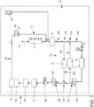
- the Figs. 1 to 5 show in greatly simplified representations a motor vehicle 1 according to the invention with a cooling system 2.
- the cooling system 2 comprises, as components to be integrated, an electric traction motor 3, an ambient heat exchanger 4, a DC-DC converter 5, a second electric coolant pump 6, a traction battery 7, a electric coolant heating device 8, a coolant-refrigerant heat exchanger 9 of an air conditioning device (otherwise not shown), a first electric coolant pump 10, a first charger 11 for charging the traction battery 7, which is based on inductive energy transfer, a second charger 12 for charging the traction battery 7 , in which an electrically conductive connection with an electrical energy source is to be established by means of a plug connection, as well as power electronics 13 assigned to traction motor 3, which can in particular include a pulse-controlled inverter.
- thermostatic valve 16 which can be designed, for example, in the form of a purely passive valve operated by means of an expansion element, includes. Furthermore, a bypass 17 to the ambient heat exchanger 4 is provided, the flow of coolant being controlled via the ambient heat exchanger 4 and / or the bypass 17 by means of the thermostatic valve 16. For example, it can be provided that the thermostatic valve 16 begins to open at a temperature of the coolant applied to it (and thus of its expansion element) of approx. 15 ° C and is fully open at a temperature of approx. 25 ° C.
- the entire volume flow of the coolant arriving at the thermostatic valve 16 is accordingly via the bypass 17 and at a temperature above approx. 25 ° C completely via the ambient heat exchanger 4 guided.
- the cooling system also has an expansion tank 18 in a known manner.
- the interconnection of the components by means of the coolant lines and the two switching valves 14, 15 is selected in such a way that the traction motor 3, the combination of ambient heat exchanger 4 and associated bypass 17, the DC-DC converter 5, the second coolant pump 6, the traction battery 3, the first coolant pump 10, the first charger 11, the second charger 12 and the power electronics 13 are integrated in series into a main circuit of the cooling system and consequently the same coolant would flow through one after the other in a coolant circuit corresponding to the main circuit. Furthermore, the interconnection is selected such that the traction motor 3, the DC-DC converter 5 and the chargers 11, 12 always when at least the first coolant pump 10 is in operation would flow through jointly (in series). For the sake of simplicity, these components of the cooling system are also referred to below as high-temperature cooling components.
- the coolant heating device 8 is integrated in a first short-circuit line 19 which bridges a section of the main circuit comprising the traction battery 7 and the second coolant pump 6.
- the coolant-refrigerant heat exchanger 9 is integrated in a second short-circuit line 20, which bridges a section of the main circuit that integrates the traction battery 7, the second coolant pump 6 and the branches 21 to the first short-circuit line 19.
- a third short-circuit line 22 is provided, which bridges a section of the main circuit integrating the traction battery 7, the second coolant pump 6, the branches 21 to the first short-circuit line 19 and the branches 23 to the second short-circuit line 20.
- a first (14) of the switching valves 14, 15 of the distribution system is integrated into the branch 21 of the main circuit to the first short-circuit line 19, which is located downstream with respect to the conveying direction provided for the second coolant pump 6.
- coolant coming from the traction battery 7 is either guided further along the main circuit or into the first short-circuit line 19.
- the second (15) of the switching valves 14, 15 of the distribution system is integrated into the branch 24 of the main circuit to the third short-circuit line 22, which is located on the suction side of the first coolant pump 10.
- coolant coming from the DC-DC converter 5 is either guided further along the main circuit or into the third short-circuit line 22.
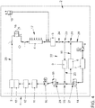
- Figs. 1 to 5 show the same cooling system in different operating modes, which are based on different functional positions of the distribution system or the switching valves 14, 15 and the thermostatic valve 16. Those coolant lines (including the bypass 17) through which the relevant volume flows of the coolant are routed in the respective operating modes are shown with thicker lines compared to those coolant lines for which this does not apply.
- the Fig. 1 shows an operation of the cooling system based on a third functional position of the distribution system.
- coolant is conveyed by means of the first coolant pump 10 in a fifth coolant circuit comprising (exclusively) the high-temperature cooling components and the bypass 17 to the ambient heat exchanger 4.
- coolant is supplied by means of the second coolant pump 6 in the second coolant circuit 26, which is separate from the fifth coolant circuit 25 and which exclusively includes the traction battery 7 and the Coolant heating device 8 comprises, promoted.
- Such an operation of the cooling system is provided after a cold start of the motor vehicle 1 at relatively low ambient and therefore also cell temperatures (e.g.
- the cooling system can be operated based on a first functional position according to FIG Fig. 2 be switched. Alternatively, however, it is also possible to operate the cooling system based on the first functional position directly after a cold start of the motor vehicle 1 at relatively low ambient and therefore also cell temperatures.
- the operation based on the first functional position according to Fig. 2 differs from that according to the Fig. 1 only to the effect that the coolant that was previously circulated in the fifth coolant circuit 25 no longer flows through the third short-circuit line 22 as a result of switching over the second switching valve 15 but through the second short-circuit line 20 comprising the coolant-refrigerant heat exchanger 9 and thus within a first coolant circuit 27 circulates.
- the sufficiently heated coolant that flows in this first coolant circuit 27 is then used to transfer thermal energy in the coolant-refrigerant heat exchanger 9 to a refrigerant of a cycle device of the air conditioning unit, which can be operated as a heat pump to convert air, which is to be fed to an interior of the motor vehicle 1 to be heated as well as possible.
- coolant is conveyed by means of the two coolant pumps 6, 10 in a seventh coolant circuit 28 corresponding to the main circuit when the bypass is activated.
- a relatively small, but not insignificant amount of Coolant flow via the second short-circuit line 26 and the coolant-refrigerant heat exchanger 9 integrated therein.
- the air conditioning unit can be deactivated during such an operation of the cooling system, there is then no or only an insignificant transfer of thermal energy from the coolant to the refrigerant of the air conditioning unit.
- Such an operation of the cooling system can be based on an operation based on the first functional position according to FIG Fig.
- An operation of the cooling system based on the fifth functional position of the distribution system according to FIG Fig. 3 an operation based on a fourth functional position according to FIG Fig. 4 connect.
- All of the components to be cooled, which are integrated into the cooling system, are then cooled by means of the same coolant, which is guided serially through these components when flowing through a corresponding sixth coolant circuit 29, and the thermal energy transferred to the coolant is, if not partially is used by operating the air conditioner to heat the interior of the motor vehicle, released as waste heat via the ambient heat exchanger 4 to the ambient air.
- An operation of the cooling system based on the fourth functional position according to FIG Fig. 4 can, depending on the power requirement on the traction motor 3 and thus also on the traction battery 7 as well as depending on the ambient temperature, be provided permanently or as a normal operating mode after the components of the cooling system to be cooled have reached their respective intended operating temperature ranges.
- the cooling performance that can be achieved during operation based on the fourth functional position according to Fig. 4 is achievable for the traction battery 7, at a relatively high ambient temperature and / or with a relatively high cooling power requirement on the traction motor and the traction battery, at least temporarily not be sufficient to maintain the upper limit of the operating temperature range provided for the traction battery 7.
- coolant is conveyed by means of the first coolant pump 10 in a third coolant circuit 30 comprising the high-temperature cooling components and the ambient heat exchanger 4 in addition to the first coolant pump 15, and also coolant by means of the second coolant pump 14 in a traction battery 7 and the coolant-refrigerant heat exchanger 9 comprising fourth coolant circuit 31, which is separate from the third coolant circuit 30, promoted.
- the air conditioner comprising the coolant-refrigerant heat exchanger 9 is operated at the same time as a refrigeration machine and thereby generates a particularly high cooling capacity for cooling the traction battery 7.
Claims (9)
- Véhicule automobile (1) pourvu d'un système de refroidissement, comprenant- un moteur de traction électrique (3),- un échangeur de chaleur ambiante (4),- une batterie de traction (7),- un dispositif de chauffage de produit réfrigérant (8),- un échangeur de chaleur de liquide de refroidissement/ fluide frigorigène (9) d'un climatiseur,- une première pompe à liquide de refroidissement (10), et- une deuxième pompe à liquide de refroidissement (6),qui sont ou peuvent être reliés les uns aux autres directement ou indirectement par des conduites de liquide de refroidissement et un système de distribution,
caractérisé en ce que le système de refroidissement comprend une dérivation (17) vers l'échangeur de chaleur ambiante (4), et en ce que- dans une première position fonctionnelle du système de distribution,- du liquide de refroidissement peut être débité au moyen de la première pompe à liquide de refroidissement (10) dans un premier circuit de liquide de refroidissement (27) comprenant le moteur de traction (3), la dérivation (17) vers l'échangeur de chaleur ambiante (4) et l'échangeur de chaleur à liquide de refroidissement/ fluide frigorigène (9), et- du liquide de refroidissement peut être débité au moyen de la deuxième pompe à liquide de refroidissement (6) dans un deuxième circuit de liquide de refroidissement (26) comprenant la batterie de traction (7) et le dispositif de chauffage de liquide de refroidissement (8) et qui est séparé du premier circuit de liquide de refroidissement (27), et- dans une deuxième position fonctionnelle du système de distribution,- du liquide de refroidissement peut être débité au moyen de la première pompe à liquide de refroidissement (10) dans un troisième circuit de liquide de refroidissement (30) comprenant le moteur de traction (3) et l'échangeur de chaleur ambiante (4), et- du liquide de refroidissement peut être débité au moyen de la deuxième pompe à liquide de refroidissement (6) dans un quatrième circuit de liquide de refroidissement (31) comprenant la batterie de traction (7) et l'échangeur de chaleur à liquide de refroidissement/ fluide frigorigène (9) et qui est séparé du troisième circuit de liquide de refroidissement (30). - Véhicule automobile (1) selon la revendication 1, caractérisé en ce que dans une troisième position fonctionnelle du système de distribution,- du liquide de refroidissement peut être débité au moyen de la première pompe à liquide de refroidissement (10) dans un cinquième circuit de liquide de refroidissement (25) comprenant le moteur de traction (3) et la dérivation (17) vers l'échangeur de chaleur ambiante (4), et- liquide de refroidissement peut être débité au moyen de la deuxième pompe à liquide de refroidissement (6) dans le deuxième circuit de liquide de refroidissement (26) qui est séparé du cinquième circuit de liquide de refroidissement (25).
- Véhicule automobile (1) selon la revendication 1 ou 2, caractérisé en ce que dans une quatrième position fonctionnelle du système de distribution, du liquide de refroidissement peut être débité au moyen de la première pompe à liquide de refroidissement (10) et de la deuxième pompe à liquide de refroidissement (6) dans un sixième circuit de liquide de refroidissement (29) comprenant le moteur de traction (3), l'échangeur de chaleur ambiante (4) et la batterie de traction (7).
- Véhicule automobile (1) selon l'une quelconque des revendications précédentes, caractérisé en ce que dans une cinquième position fonctionnelle du système de distribution, du liquide de refroidissement peut être débité au moyen de la première pompe à liquide de refroidissement (10) et de la deuxième pompe à liquide de refroidissement (6) dans un septième circuit de liquide de refroidissement (28) comprenant le moteur de traction (3), la dérivation (17) vers l'échangeur de chaleur ambiante (4) et la batterie de traction (7).
- Véhicule automobile (1) selon l'une quelconque des revendications précédentes, caractérisé par- un circuit principal intégrant en série le moteur de traction (3), la combinaison de l'échangeur de chaleur ambiante (4) et de la dérivation (17) associée, la batterie de traction (7), la première pompe à liquide de refroidissement (10) et la deuxième pompe à liquide de refroidissement (6), et- une première conduite de court-circuit (19) intégrant le dispositif de chauffage de liquide de refroidissement (8) et qui court-circuite une partie du circuit principal intégrant la batterie de traction (7) et la deuxième pompe à liquide de refroidissement (6), et- une deuxième conduite de court-circuit (20) intégrant l'échangeur de chaleur à liquide de refroidissement/ fluide frigorigène (9) et qui court-circuite une partie du circuit principal intégrant la batterie de traction (7), la deuxième pompe à liquide de refroidissement (6) ainsi que les branchements (21) vers la première conduite de court-circuit (19),un premier dispositif de distribution du système de distribution étant intégré dans au moins un branchement (21, 23) vers la première conduite de court-circuit (19) et/ou vers la deuxième conduite de court-circuit (20).
- Véhicule automobile (1) selon la revendication 2 ou l'une des revendications dépendant de la revendication 2 et selon la revendication 5, caractérisé par une troisième conduite de court-circuit (22) qui court-circuite une partie du circuit principal intégrant la batterie de traction (7), la deuxième pompe à liquide de refroidissement (6), les branchements (21) vers la première conduite de court-circuit (19) et les branchements (23) vers la deuxième conduite de court-circuit (20).
- Véhicule automobile (1) selon la revendication 6, caractérisé en ce qu'un deuxième dispositif de distribution du système de distribution est intégré dans au moins un branchement (24) vers la troisième conduite de court-circuit (22).
- Véhicule automobile (1) selon l'une quelconque des revendications précédentes, caractérisé par une configuration sous forme de véhicule électrique.
- Procédé d'exploitation d'un véhicule automobile (1) selon l'une quelconque des revendications précédentes, caractérisé en ce que- dans la première position fonctionnelle du système de distribution, de l'énergie thermique qui passe dans l'échangeur de chaleur à liquide de refroidissement/ fluide frigorigène (9) du liquide de refroidissement s'écoulant par le premier circuit de refroidissement de liquide de refroidissement (27) à un fluide frigorigène du climatiseur, est utilisée pour chauffer un habitacle du véhicule automobile (1), et/ou- dans une deuxième position fonctionnelle du système de distribution, de l'énergie thermique qui passe dans l'échangeur de chaleur de liquide de refroidissement/ fluide frigorigène (9) du liquide de refroidissement s'écoulant par le quatrième circuit de refroidissement de liquide de refroidissement (31) au fluide frigorigène du climatiseur, est utilisée pour refroidir la batterie de traction (7).
Applications Claiming Priority (1)
| Application Number | Priority Date | Filing Date | Title |
|---|---|---|---|
| DE102017120615.9A DE102017120615A1 (de) | 2017-09-07 | 2017-09-07 | Kraftfahrzeug mit einem Kühlsystem |
Publications (2)
| Publication Number | Publication Date |
|---|---|
| EP3454401A1 EP3454401A1 (fr) | 2019-03-13 |
| EP3454401B1 true EP3454401B1 (fr) | 2021-05-19 |
Family
ID=63449221
Family Applications (1)
| Application Number | Title | Priority Date | Filing Date |
|---|---|---|---|
| EP18191416.9A Active EP3454401B1 (fr) | 2017-09-07 | 2018-08-29 | Véhicule automobile pourvu d'un système de refroidissement |
Country Status (4)
| Country | Link |
|---|---|
| US (1) | US10773586B2 (fr) |
| EP (1) | EP3454401B1 (fr) |
| CN (1) | CN109466272B (fr) |
| DE (1) | DE102017120615A1 (fr) |
Families Citing this family (26)
| Publication number | Priority date | Publication date | Assignee | Title |
|---|---|---|---|---|
| GB2555475B (en) * | 2016-10-31 | 2019-12-18 | Williams Advanced Engineering Ltd | A heating and cooling system for an electric vehicle |
| US11001250B2 (en) * | 2018-03-01 | 2021-05-11 | Cummins Inc. | Waste heat recovery hybrid power drive |
| DE102018218474A1 (de) * | 2018-10-29 | 2020-04-30 | Robert Bosch Gmbh | Heiz- oder Kühlmittelkreislauf für ein Elektrofahrzeug |
| JP7251229B2 (ja) * | 2019-03-13 | 2023-04-04 | トヨタ自動車株式会社 | 車載温調装置 |
| DE102019107194A1 (de) * | 2019-03-20 | 2020-09-24 | Bayerische Motoren Werke Aktiengesellschaft | Steuerungssystem für ein Wärmesystem sowie Verfahren zum Betrieb eines Wärmesystems |
| DE102019107191A1 (de) * | 2019-03-20 | 2020-09-24 | Bayerische Motoren Werke Aktiengesellschaft | Wärmesystem für ein Elektro- oder Hybridfahrzeug, Elektro- oder Hybridfahrzeug, Verfahren zum Betrieb eines Wärmesystems |
| CN110165336A (zh) * | 2019-04-12 | 2019-08-23 | 汉腾汽车有限公司 | 一种电动汽车动力电池温控装置 |
| DE102019210029A1 (de) * | 2019-07-08 | 2021-01-14 | Volkswagen Aktiengesellschaft | Kühlkreislauf |
| DE102019210030A1 (de) * | 2019-07-08 | 2021-01-14 | Volkswagen Aktiengesellschaft | Verfahren zur Regelung eines Volumenstroms |
| DE102019210967A1 (de) * | 2019-07-24 | 2021-01-28 | Volkswagen Aktiengesellschaft | Kühlkreislauf |
| JP7115452B2 (ja) * | 2019-09-30 | 2022-08-09 | トヨタ自動車株式会社 | 冷却システム |
| WO2021087620A1 (fr) * | 2019-11-07 | 2021-05-14 | Taiga Motors, Inc. | Système de gestion thermique pour véhicule électrique |
| DE102019130803B4 (de) | 2019-11-14 | 2021-09-16 | Bayerische Motoren Werke Aktiengesellschaft | Verfahren zum Wärmemanagement eines Kraftfahrzeugs |
| CN113054261A (zh) * | 2019-12-26 | 2021-06-29 | 奥动新能源汽车科技有限公司 | 冷却组件及包括其的充换电站、储能站 |
| DE102020101159A1 (de) | 2020-01-20 | 2021-07-22 | Volkswagen Aktiengesellschaft | Elektrisches Kraftfahrzeug mit Kühlmittelkühler und zugeordneter Widerstandsheizvorrichtung |
| SE544141C2 (en) * | 2020-03-23 | 2022-01-11 | Scania Cv Ab | A temperature control system, a vehicle provided therewith and a method for controlling the operation thereof |
| DE102020204555A1 (de) | 2020-04-08 | 2021-10-14 | Denso Corporation | Kühlkreislauf mit mehreren Kühltemperaturen für Kraftfahrzeuge und ein Verfahren zum Betrieb eines solchen Kühlkreislaufs |
| DE102020206529A1 (de) * | 2020-05-26 | 2021-12-02 | Ford Global Technologies, Llc | System zum Kühlen einer Batterie eines Kraftfahrzeugs, sowie Kraftfahrzeug |
| KR20220007758A (ko) * | 2020-07-09 | 2022-01-19 | 현대자동차주식회사 | 차량 전력계통의 열관리 시스템 |
| CN112151906A (zh) * | 2020-08-31 | 2020-12-29 | 珠海格力电器股份有限公司 | 一种电池的冷却方法、装置及系统 |
| CN116458042A (zh) * | 2020-11-20 | 2023-07-18 | 尼得科株式会社 | 调温装置 |
| WO2022185561A1 (fr) * | 2021-03-03 | 2022-09-09 | 日本電産株式会社 | Dispositif de régulation de température |
| KR20220152604A (ko) * | 2021-05-10 | 2022-11-17 | 현대자동차주식회사 | 차량의 열관리 시스템 |
| JP2022190760A (ja) * | 2021-06-15 | 2022-12-27 | トヨタ自動車株式会社 | 熱管理システム |
| CN113442701A (zh) * | 2021-06-29 | 2021-09-28 | 东风汽车集团股份有限公司 | 一种适用于电动汽车的液冷控制方法及系统 |
| DE102022122765A1 (de) * | 2022-09-08 | 2024-03-14 | Bayerische Motoren Werke Aktiengesellschaft | Verfahren zum Betreiben eines Kraftfahrzeugs und Kraftfahrzeug |
Family Cites Families (23)
| Publication number | Priority date | Publication date | Assignee | Title |
|---|---|---|---|---|
| US7287581B2 (en) * | 2003-12-18 | 2007-10-30 | General Motors Corporation | Full function vehicle HVAC/PTC thermal system |
| DE102007004979A1 (de) | 2007-02-01 | 2008-08-07 | Daimler Ag | Vorrichtung zur Kühlung einer Hybridfahrzeugbatterie |
| DE102009042774A1 (de) * | 2009-09-25 | 2011-03-31 | Behr Gmbh & Co. Kg | System für ein Kraftfahrzeug zum Erwärmen und/oder Kühlen einer Batterie und eines Kraftfahrzeuginnenraumes |
| DE102009059240B4 (de) * | 2009-12-21 | 2013-08-01 | Webasto Ag | Kraftfahrzeug-Kühlsystem |
| US8997503B2 (en) * | 2010-01-15 | 2015-04-07 | Mitsubishi Heavy Industries, Ltd. | Vehicle air-conditioning system and operation control method therefor |
| DE102010042195A1 (de) * | 2010-10-08 | 2012-04-12 | Robert Bosch Gmbh | Klimatisierungsvorrichtung und Verfahren zum Klimatisieren eines Innenraums und/oder mindestens eines Bauteils eines Elektrofahrzeuges |
| US20120168138A1 (en) * | 2010-12-30 | 2012-07-05 | Hyundai Motor Company | Integrated pump, coolant flow control and heat exchange device |
| DE102013105747B4 (de) * | 2012-07-18 | 2022-06-09 | Hanon Systems | Vorrichtungen zur Wärmeverteilung in einem Kraftfahrzeug |
| DE102012108043A1 (de) * | 2012-08-30 | 2014-05-15 | Dr. Ing. H.C. F. Porsche Aktiengesellschaft | Temperierungsanordnung |
| CN102941791B (zh) * | 2012-11-08 | 2014-12-03 | 上海汽车集团股份有限公司 | 电动车综合热循环系统 |
| DE102012024080A1 (de) | 2012-12-07 | 2014-03-20 | Daimler Ag | Fahrzeug mit Elektromotor |
| US10046617B2 (en) * | 2013-02-01 | 2018-08-14 | Ford Global Technologies, Llc | Electric vehicle multi-loop thermal management system |
| DE102013019687B3 (de) * | 2013-11-26 | 2015-03-26 | Audi Ag | Kühlsystem für ein Hybridfahrzeug aufweisend zumindest eine elektrische Antriebsmaschine und zumindest eine Verbrennungskraftmaschine und Verfahren zu dessen Regelung |
| US9914338B2 (en) * | 2014-03-06 | 2018-03-13 | GM Global Technology Operations LLC | Thermal management system for a vehicle |
| US10211493B2 (en) | 2014-05-16 | 2019-02-19 | Ford Global Technologies, Llc | Thermal management system for an electrified vehicle |
| US20160023532A1 (en) * | 2014-07-25 | 2016-01-28 | Atieva, Inc. | EV Integrated Temperature Control System |
| FR3024961B1 (fr) * | 2014-08-19 | 2016-08-12 | Renault Sa | "dispositif de regulation thermique d'une batterie comportant un evaporateur de refroidissement de la batterie et un radiateur de chauffage de la batterie" |
| US9758010B2 (en) * | 2014-10-21 | 2017-09-12 | Atieva, Inc. | EV multi mode thermal management system |
| DE102015101186B4 (de) | 2015-01-28 | 2024-04-18 | Dr. Ing. H.C. F. Porsche Aktiengesellschaft | Klimakreislauf für ein elektrisch antreibbares Kraftfahrzeug, sowie Verfahren zum Vorheizen einer Traktionsbatterie eines elektrisch antreibbaren Kraftfahrzeugs |
| US20160344075A1 (en) * | 2015-05-20 | 2016-11-24 | Ford Global Technologies, Llc | Thermal Management System for a Vehicle |
| DE102015220623B4 (de) | 2015-10-22 | 2022-01-27 | Bayerische Motoren Werke Aktiengesellschaft | Wärmesystem für ein Elektro- oder Hybridfahrzeug |
| KR101855759B1 (ko) * | 2015-12-08 | 2018-05-09 | 현대자동차 주식회사 | 차량용 배터리 냉각 시스템 |
| CN106585414B (zh) | 2016-12-27 | 2018-01-19 | 上海思致汽车工程技术有限公司 | 一种智能化多回路电动汽车冷却系统 |
-
2017
- 2017-09-07 DE DE102017120615.9A patent/DE102017120615A1/de active Pending
-
2018
- 2018-08-29 EP EP18191416.9A patent/EP3454401B1/fr active Active
- 2018-09-06 CN CN201811036071.1A patent/CN109466272B/zh active Active
- 2018-09-07 US US16/124,640 patent/US10773586B2/en active Active
Non-Patent Citations (1)
| Title |
|---|
| None * |
Also Published As
| Publication number | Publication date |
|---|---|
| CN109466272A (zh) | 2019-03-15 |
| EP3454401A1 (fr) | 2019-03-13 |
| US20190070951A1 (en) | 2019-03-07 |
| DE102017120615A1 (de) | 2019-03-07 |
| US10773586B2 (en) | 2020-09-15 |
| CN109466272B (zh) | 2022-06-03 |
Similar Documents
| Publication | Publication Date | Title |
|---|---|---|
| EP3454401B1 (fr) | Véhicule automobile pourvu d'un système de refroidissement | |
| DE102015220623B4 (de) | Wärmesystem für ein Elektro- oder Hybridfahrzeug | |
| WO2019096696A1 (fr) | Système de refroidissement pour véhicule automobile et véhicule automobile muni dudit système de refroidissement | |
| DE102019132688A1 (de) | Wärmemanagementsystem für ein Kraftfahrzeug und Verfahren zum Wärmemanagement eines Kraftfahrzeugs | |
| DE102009060860A1 (de) | Klimatisierungssystem für ein Fahrzeug sowie Verfahren zum Temperieren | |
| DE102014116350A1 (de) | Klimakreislauf für ein Hybridkraftfahrzeug sowie Verfahren zum Vorheizen einer Kraftfahrzeugbatterie eines Hybridkraftfahrzeugs | |
| DE102013206630A1 (de) | Kühl- und Heizsystem für ein Elektro- oder Hybrid-Fahrzeug sowie Verfahren zum Betreiben eines derartigen Kühl- und Heizsystems | |
| DE102020107111A1 (de) | Wärmepumpenanordnung für Fahrzeuge mit einem Fahrzeugkabinenheizkreislauf und einem Batterieheizkreislauf | |
| WO2014086443A1 (fr) | Véhicule à moteur électrique | |
| DE102020117471B4 (de) | Wärmepumpenanordnung mit indirekter Batterieerwärmung für batteriebetriebene Kraftfahrzeuge und Verfahren zum Betreiben einer Wärmepumpenanordnung | |
| DE102016203045A1 (de) | Temperiereinrichtung zum Temperieren eines Innenraums eines Fahrzeugs sowie Verfahren zum Betreiben einer solchen Temperiereinrichtung | |
| WO2017092853A1 (fr) | Agencement de piles à combustible, procédé pour faire fonctionner un tel agencement de piles à combustible et utilisation d'un tel agencement de piles à combustible | |
| WO2014037216A1 (fr) | Procédé de conditionnement thermique d'un moteur à combustion interne et/ou de l'habitacle d'un véhicule et véhicule correspondant | |
| DE102021127770A1 (de) | Thermomanagementsystem für ein Kraftfahrzeug und Kraftfahrzeug mit einem solchen | |
| DE102020130911B3 (de) | Kältemittelkreislauf für eine Fahrzeugklimaanlage | |
| DE102017201686B4 (de) | Verfahren zum Betreiben einer Kälteanlage eines Fahrzeugs | |
| DE102019132816A1 (de) | Wärmemanagementsystem für ein Kraftfahrzeug und Kraftfahrzeug mit einem solchen | |
| WO2014154326A1 (fr) | Système de climatisation pour véhicule | |
| DE102019120229A1 (de) | Wärmemanagementsystem für ein Kraftfahrzeug, Verfahren zum Wärmemanagement eines Kraftfahrzeugs und Kraftfahrzeug mit einem Wärmemanagementsystem | |
| DE102018205345B4 (de) | Elektromotor mit Flüssigkeitskühlung und Verwendung eines derartigen Elektromotors | |
| EP3015674B1 (fr) | Moteur à combustion interne suralimenté et procédé de fonctionnement correspondant | |
| DE102018205393A1 (de) | Temperierungssystem für eine Batterie | |
| DE102009005638B4 (de) | Fahrzeugtemperiersystem, insbesondere zur thermischen Behandlung der in einen Fahrzeuginnenraum einzuleitenden Luft | |
| EP2986460B1 (fr) | Installation de pompe à chaleur pour véhicule et procédé de fonctionnement d'une installation de pompe à chaleur correspondante | |
| EP4059747A1 (fr) | Système de gestion thermique pour un véhicule automobile doté d'un système de thermorégulation et d'un système de transfert séparé de ceux-ci |
Legal Events
| Date | Code | Title | Description |
|---|---|---|---|
| PUAI | Public reference made under article 153(3) epc to a published international application that has entered the european phase |
Free format text: ORIGINAL CODE: 0009012 |
|
| STAA | Information on the status of an ep patent application or granted ep patent |
Free format text: STATUS: THE APPLICATION HAS BEEN PUBLISHED |
|
| AK | Designated contracting states |
Kind code of ref document: A1 Designated state(s): AL AT BE BG CH CY CZ DE DK EE ES FI FR GB GR HR HU IE IS IT LI LT LU LV MC MK MT NL NO PL PT RO RS SE SI SK SM TR |
|
| AX | Request for extension of the european patent |
Extension state: BA ME |
|
| STAA | Information on the status of an ep patent application or granted ep patent |
Free format text: STATUS: REQUEST FOR EXAMINATION WAS MADE |
|
| 17P | Request for examination filed |
Effective date: 20190913 |
|
| RBV | Designated contracting states (corrected) |
Designated state(s): AL AT BE BG CH CY CZ DE DK EE ES FI FR GB GR HR HU IE IS IT LI LT LU LV MC MK MT NL NO PL PT RO RS SE SI SK SM TR |
|
| GRAP | Despatch of communication of intention to grant a patent |
Free format text: ORIGINAL CODE: EPIDOSNIGR1 |
|
| STAA | Information on the status of an ep patent application or granted ep patent |
Free format text: STATUS: GRANT OF PATENT IS INTENDED |
|
| GRAJ | Information related to disapproval of communication of intention to grant by the applicant or resumption of examination proceedings by the epo deleted |
Free format text: ORIGINAL CODE: EPIDOSDIGR1 |
|
| STAA | Information on the status of an ep patent application or granted ep patent |
Free format text: STATUS: REQUEST FOR EXAMINATION WAS MADE |
|
| GRAP | Despatch of communication of intention to grant a patent |
Free format text: ORIGINAL CODE: EPIDOSNIGR1 |
|
| STAA | Information on the status of an ep patent application or granted ep patent |
Free format text: STATUS: GRANT OF PATENT IS INTENDED |
|
| INTG | Intention to grant announced |
Effective date: 20210202 |
|
| INTC | Intention to grant announced (deleted) | ||
| INTG | Intention to grant announced |
Effective date: 20210303 |
|
| RIN1 | Information on inventor provided before grant (corrected) |
Inventor name: SCHULZE, TOBIAS Inventor name: LUCKE, STEFAN Inventor name: STELZNER, ROBERT Inventor name: REUTERS, ULF |
|
| GRAS | Grant fee paid |
Free format text: ORIGINAL CODE: EPIDOSNIGR3 |
|
| GRAA | (expected) grant |
Free format text: ORIGINAL CODE: 0009210 |
|
| STAA | Information on the status of an ep patent application or granted ep patent |
Free format text: STATUS: THE PATENT HAS BEEN GRANTED |
|
| AK | Designated contracting states |
Kind code of ref document: B1 Designated state(s): AL AT BE BG CH CY CZ DE DK EE ES FI FR GB GR HR HU IE IS IT LI LT LU LV MC MK MT NL NO PL PT RO RS SE SI SK SM TR |
|
| REG | Reference to a national code |
Ref country code: GB Ref legal event code: FG4D Free format text: NOT ENGLISH |
|
| REG | Reference to a national code |
Ref country code: CH Ref legal event code: EP |
|
| REG | Reference to a national code |
Ref country code: DE Ref legal event code: R096 Ref document number: 502018005298 Country of ref document: DE |
|
| REG | Reference to a national code |
Ref country code: AT Ref legal event code: REF Ref document number: 1394862 Country of ref document: AT Kind code of ref document: T Effective date: 20210615 |
|
| REG | Reference to a national code |
Ref country code: IE Ref legal event code: FG4D Free format text: LANGUAGE OF EP DOCUMENT: GERMAN |
|
| REG | Reference to a national code |
Ref country code: LT Ref legal event code: MG9D |
|
| REG | Reference to a national code |
Ref country code: NL Ref legal event code: MP Effective date: 20210519 |
|
| PG25 | Lapsed in a contracting state [announced via postgrant information from national office to epo] |
Ref country code: FI Free format text: LAPSE BECAUSE OF FAILURE TO SUBMIT A TRANSLATION OF THE DESCRIPTION OR TO PAY THE FEE WITHIN THE PRESCRIBED TIME-LIMIT Effective date: 20210519 Ref country code: HR Free format text: LAPSE BECAUSE OF FAILURE TO SUBMIT A TRANSLATION OF THE DESCRIPTION OR TO PAY THE FEE WITHIN THE PRESCRIBED TIME-LIMIT Effective date: 20210519 Ref country code: LT Free format text: LAPSE BECAUSE OF FAILURE TO SUBMIT A TRANSLATION OF THE DESCRIPTION OR TO PAY THE FEE WITHIN THE PRESCRIBED TIME-LIMIT Effective date: 20210519 Ref country code: BG Free format text: LAPSE BECAUSE OF FAILURE TO SUBMIT A TRANSLATION OF THE DESCRIPTION OR TO PAY THE FEE WITHIN THE PRESCRIBED TIME-LIMIT Effective date: 20210819 |
|
| PG25 | Lapsed in a contracting state [announced via postgrant information from national office to epo] |
Ref country code: IS Free format text: LAPSE BECAUSE OF FAILURE TO SUBMIT A TRANSLATION OF THE DESCRIPTION OR TO PAY THE FEE WITHIN THE PRESCRIBED TIME-LIMIT Effective date: 20210919 Ref country code: GR Free format text: LAPSE BECAUSE OF FAILURE TO SUBMIT A TRANSLATION OF THE DESCRIPTION OR TO PAY THE FEE WITHIN THE PRESCRIBED TIME-LIMIT Effective date: 20210820 Ref country code: RS Free format text: LAPSE BECAUSE OF FAILURE TO SUBMIT A TRANSLATION OF THE DESCRIPTION OR TO PAY THE FEE WITHIN THE PRESCRIBED TIME-LIMIT Effective date: 20210519 Ref country code: SE Free format text: LAPSE BECAUSE OF FAILURE TO SUBMIT A TRANSLATION OF THE DESCRIPTION OR TO PAY THE FEE WITHIN THE PRESCRIBED TIME-LIMIT Effective date: 20210519 Ref country code: NO Free format text: LAPSE BECAUSE OF FAILURE TO SUBMIT A TRANSLATION OF THE DESCRIPTION OR TO PAY THE FEE WITHIN THE PRESCRIBED TIME-LIMIT Effective date: 20210819 Ref country code: PL Free format text: LAPSE BECAUSE OF FAILURE TO SUBMIT A TRANSLATION OF THE DESCRIPTION OR TO PAY THE FEE WITHIN THE PRESCRIBED TIME-LIMIT Effective date: 20210519 Ref country code: PT Free format text: LAPSE BECAUSE OF FAILURE TO SUBMIT A TRANSLATION OF THE DESCRIPTION OR TO PAY THE FEE WITHIN THE PRESCRIBED TIME-LIMIT Effective date: 20210920 Ref country code: LV Free format text: LAPSE BECAUSE OF FAILURE TO SUBMIT A TRANSLATION OF THE DESCRIPTION OR TO PAY THE FEE WITHIN THE PRESCRIBED TIME-LIMIT Effective date: 20210519 |
|
| PG25 | Lapsed in a contracting state [announced via postgrant information from national office to epo] |
Ref country code: NL Free format text: LAPSE BECAUSE OF FAILURE TO SUBMIT A TRANSLATION OF THE DESCRIPTION OR TO PAY THE FEE WITHIN THE PRESCRIBED TIME-LIMIT Effective date: 20210519 |
|
| PG25 | Lapsed in a contracting state [announced via postgrant information from national office to epo] |
Ref country code: SM Free format text: LAPSE BECAUSE OF FAILURE TO SUBMIT A TRANSLATION OF THE DESCRIPTION OR TO PAY THE FEE WITHIN THE PRESCRIBED TIME-LIMIT Effective date: 20210519 Ref country code: SK Free format text: LAPSE BECAUSE OF FAILURE TO SUBMIT A TRANSLATION OF THE DESCRIPTION OR TO PAY THE FEE WITHIN THE PRESCRIBED TIME-LIMIT Effective date: 20210519 Ref country code: EE Free format text: LAPSE BECAUSE OF FAILURE TO SUBMIT A TRANSLATION OF THE DESCRIPTION OR TO PAY THE FEE WITHIN THE PRESCRIBED TIME-LIMIT Effective date: 20210519 Ref country code: ES Free format text: LAPSE BECAUSE OF FAILURE TO SUBMIT A TRANSLATION OF THE DESCRIPTION OR TO PAY THE FEE WITHIN THE PRESCRIBED TIME-LIMIT Effective date: 20210519 Ref country code: RO Free format text: LAPSE BECAUSE OF FAILURE TO SUBMIT A TRANSLATION OF THE DESCRIPTION OR TO PAY THE FEE WITHIN THE PRESCRIBED TIME-LIMIT Effective date: 20210519 Ref country code: CZ Free format text: LAPSE BECAUSE OF FAILURE TO SUBMIT A TRANSLATION OF THE DESCRIPTION OR TO PAY THE FEE WITHIN THE PRESCRIBED TIME-LIMIT Effective date: 20210519 Ref country code: DK Free format text: LAPSE BECAUSE OF FAILURE TO SUBMIT A TRANSLATION OF THE DESCRIPTION OR TO PAY THE FEE WITHIN THE PRESCRIBED TIME-LIMIT Effective date: 20210519 |
|
| REG | Reference to a national code |
Ref country code: DE Ref legal event code: R097 Ref document number: 502018005298 Country of ref document: DE |
|
| PLBE | No opposition filed within time limit |
Free format text: ORIGINAL CODE: 0009261 |
|
| STAA | Information on the status of an ep patent application or granted ep patent |
Free format text: STATUS: NO OPPOSITION FILED WITHIN TIME LIMIT |
|
| REG | Reference to a national code |
Ref country code: CH Ref legal event code: PL |
|
| PG25 | Lapsed in a contracting state [announced via postgrant information from national office to epo] |
Ref country code: MC Free format text: LAPSE BECAUSE OF FAILURE TO SUBMIT A TRANSLATION OF THE DESCRIPTION OR TO PAY THE FEE WITHIN THE PRESCRIBED TIME-LIMIT Effective date: 20210519 |
|
| REG | Reference to a national code |
Ref country code: BE Ref legal event code: MM Effective date: 20210831 |
|
| 26N | No opposition filed |
Effective date: 20220222 |
|
| PG25 | Lapsed in a contracting state [announced via postgrant information from national office to epo] |
Ref country code: LI Free format text: LAPSE BECAUSE OF NON-PAYMENT OF DUE FEES Effective date: 20210831 Ref country code: CH Free format text: LAPSE BECAUSE OF NON-PAYMENT OF DUE FEES Effective date: 20210831 |
|
| PG25 | Lapsed in a contracting state [announced via postgrant information from national office to epo] |
Ref country code: IS Free format text: LAPSE BECAUSE OF FAILURE TO SUBMIT A TRANSLATION OF THE DESCRIPTION OR TO PAY THE FEE WITHIN THE PRESCRIBED TIME-LIMIT Effective date: 20210919 Ref country code: LU Free format text: LAPSE BECAUSE OF NON-PAYMENT OF DUE FEES Effective date: 20210829 Ref country code: AL Free format text: LAPSE BECAUSE OF FAILURE TO SUBMIT A TRANSLATION OF THE DESCRIPTION OR TO PAY THE FEE WITHIN THE PRESCRIBED TIME-LIMIT Effective date: 20210519 |
|
| PG25 | Lapsed in a contracting state [announced via postgrant information from national office to epo] |
Ref country code: IT Free format text: LAPSE BECAUSE OF FAILURE TO SUBMIT A TRANSLATION OF THE DESCRIPTION OR TO PAY THE FEE WITHIN THE PRESCRIBED TIME-LIMIT Effective date: 20210519 Ref country code: IE Free format text: LAPSE BECAUSE OF NON-PAYMENT OF DUE FEES Effective date: 20210829 Ref country code: BE Free format text: LAPSE BECAUSE OF NON-PAYMENT OF DUE FEES Effective date: 20210831 |
|
| P01 | Opt-out of the competence of the unified patent court (upc) registered |
Effective date: 20230523 |
|
| PG25 | Lapsed in a contracting state [announced via postgrant information from national office to epo] |
Ref country code: CY Free format text: LAPSE BECAUSE OF FAILURE TO SUBMIT A TRANSLATION OF THE DESCRIPTION OR TO PAY THE FEE WITHIN THE PRESCRIBED TIME-LIMIT Effective date: 20210519 |
|
| PG25 | Lapsed in a contracting state [announced via postgrant information from national office to epo] |
Ref country code: HU Free format text: LAPSE BECAUSE OF FAILURE TO SUBMIT A TRANSLATION OF THE DESCRIPTION OR TO PAY THE FEE WITHIN THE PRESCRIBED TIME-LIMIT; INVALID AB INITIO Effective date: 20180829 |
|
| PGFP | Annual fee paid to national office [announced via postgrant information from national office to epo] |
Ref country code: GB Payment date: 20230822 Year of fee payment: 6 |
|
| PGFP | Annual fee paid to national office [announced via postgrant information from national office to epo] |
Ref country code: FR Payment date: 20230824 Year of fee payment: 6 Ref country code: DE Payment date: 20230831 Year of fee payment: 6 |