US11001250B2 - Waste heat recovery hybrid power drive - Google Patents
Waste heat recovery hybrid power drive Download PDFInfo
- Publication number
- US11001250B2 US11001250B2 US15/909,578 US201815909578A US11001250B2 US 11001250 B2 US11001250 B2 US 11001250B2 US 201815909578 A US201815909578 A US 201815909578A US 11001250 B2 US11001250 B2 US 11001250B2
- Authority
- US
- United States
- Prior art keywords
- motor
- whr
- generator
- drive shaft
- output shaft
- Prior art date
- Legal status (The legal status is an assumption and is not a legal conclusion. Google has not performed a legal analysis and makes no representation as to the accuracy of the status listed.)
- Active, expires
Links
Images


Classifications
-
- F—MECHANICAL ENGINEERING; LIGHTING; HEATING; WEAPONS; BLASTING
- F01—MACHINES OR ENGINES IN GENERAL; ENGINE PLANTS IN GENERAL; STEAM ENGINES
- F01N—GAS-FLOW SILENCERS OR EXHAUST APPARATUS FOR MACHINES OR ENGINES IN GENERAL; GAS-FLOW SILENCERS OR EXHAUST APPARATUS FOR INTERNAL-COMBUSTION ENGINES
- F01N5/00—Exhaust or silencing apparatus combined or associated with devices profiting by exhaust energy
- F01N5/02—Exhaust or silencing apparatus combined or associated with devices profiting by exhaust energy the devices using heat
-
- B—PERFORMING OPERATIONS; TRANSPORTING
- B60—VEHICLES IN GENERAL
- B60W—CONJOINT CONTROL OF VEHICLE SUB-UNITS OF DIFFERENT TYPE OR DIFFERENT FUNCTION; CONTROL SYSTEMS SPECIALLY ADAPTED FOR HYBRID VEHICLES; ROAD VEHICLE DRIVE CONTROL SYSTEMS FOR PURPOSES NOT RELATED TO THE CONTROL OF A PARTICULAR SUB-UNIT
- B60W20/00—Control systems specially adapted for hybrid vehicles
- B60W20/10—Controlling the power contribution of each of the prime movers to meet required power demand
- B60W20/13—Controlling the power contribution of each of the prime movers to meet required power demand in order to stay within battery power input or output limits; in order to prevent overcharging or battery depletion
- B60W20/14—Controlling the power contribution of each of the prime movers to meet required power demand in order to stay within battery power input or output limits; in order to prevent overcharging or battery depletion in conjunction with braking regeneration
-
- B—PERFORMING OPERATIONS; TRANSPORTING
- B60—VEHICLES IN GENERAL
- B60K—ARRANGEMENT OR MOUNTING OF PROPULSION UNITS OR OF TRANSMISSIONS IN VEHICLES; ARRANGEMENT OR MOUNTING OF PLURAL DIVERSE PRIME-MOVERS IN VEHICLES; AUXILIARY DRIVES FOR VEHICLES; INSTRUMENTATION OR DASHBOARDS FOR VEHICLES; ARRANGEMENTS IN CONNECTION WITH COOLING, AIR INTAKE, GAS EXHAUST OR FUEL SUPPLY OF PROPULSION UNITS IN VEHICLES
- B60K6/00—Arrangement or mounting of plural diverse prime-movers for mutual or common propulsion, e.g. hybrid propulsion systems comprising electric motors and internal combustion engines
- B60K6/20—Arrangement or mounting of plural diverse prime-movers for mutual or common propulsion, e.g. hybrid propulsion systems comprising electric motors and internal combustion engines the prime-movers consisting of electric motors and internal combustion engines, e.g. HEVs
- B60K6/22—Arrangement or mounting of plural diverse prime-movers for mutual or common propulsion, e.g. hybrid propulsion systems comprising electric motors and internal combustion engines the prime-movers consisting of electric motors and internal combustion engines, e.g. HEVs characterised by apparatus, components or means specially adapted for HEVs
- B60K6/26—Arrangement or mounting of plural diverse prime-movers for mutual or common propulsion, e.g. hybrid propulsion systems comprising electric motors and internal combustion engines the prime-movers consisting of electric motors and internal combustion engines, e.g. HEVs characterised by apparatus, components or means specially adapted for HEVs characterised by the motors or the generators
-
- B—PERFORMING OPERATIONS; TRANSPORTING
- B60—VEHICLES IN GENERAL
- B60K—ARRANGEMENT OR MOUNTING OF PROPULSION UNITS OR OF TRANSMISSIONS IN VEHICLES; ARRANGEMENT OR MOUNTING OF PLURAL DIVERSE PRIME-MOVERS IN VEHICLES; AUXILIARY DRIVES FOR VEHICLES; INSTRUMENTATION OR DASHBOARDS FOR VEHICLES; ARRANGEMENTS IN CONNECTION WITH COOLING, AIR INTAKE, GAS EXHAUST OR FUEL SUPPLY OF PROPULSION UNITS IN VEHICLES
- B60K6/00—Arrangement or mounting of plural diverse prime-movers for mutual or common propulsion, e.g. hybrid propulsion systems comprising electric motors and internal combustion engines
- B60K6/20—Arrangement or mounting of plural diverse prime-movers for mutual or common propulsion, e.g. hybrid propulsion systems comprising electric motors and internal combustion engines the prime-movers consisting of electric motors and internal combustion engines, e.g. HEVs
- B60K6/42—Arrangement or mounting of plural diverse prime-movers for mutual or common propulsion, e.g. hybrid propulsion systems comprising electric motors and internal combustion engines the prime-movers consisting of electric motors and internal combustion engines, e.g. HEVs characterised by the architecture of the hybrid electric vehicle
- B60K6/44—Series-parallel type
-
- B—PERFORMING OPERATIONS; TRANSPORTING
- B60—VEHICLES IN GENERAL
- B60K—ARRANGEMENT OR MOUNTING OF PROPULSION UNITS OR OF TRANSMISSIONS IN VEHICLES; ARRANGEMENT OR MOUNTING OF PLURAL DIVERSE PRIME-MOVERS IN VEHICLES; AUXILIARY DRIVES FOR VEHICLES; INSTRUMENTATION OR DASHBOARDS FOR VEHICLES; ARRANGEMENTS IN CONNECTION WITH COOLING, AIR INTAKE, GAS EXHAUST OR FUEL SUPPLY OF PROPULSION UNITS IN VEHICLES
- B60K6/00—Arrangement or mounting of plural diverse prime-movers for mutual or common propulsion, e.g. hybrid propulsion systems comprising electric motors and internal combustion engines
- B60K6/20—Arrangement or mounting of plural diverse prime-movers for mutual or common propulsion, e.g. hybrid propulsion systems comprising electric motors and internal combustion engines the prime-movers consisting of electric motors and internal combustion engines, e.g. HEVs
- B60K6/42—Arrangement or mounting of plural diverse prime-movers for mutual or common propulsion, e.g. hybrid propulsion systems comprising electric motors and internal combustion engines the prime-movers consisting of electric motors and internal combustion engines, e.g. HEVs characterised by the architecture of the hybrid electric vehicle
- B60K6/48—Parallel type
-
- B—PERFORMING OPERATIONS; TRANSPORTING
- B60—VEHICLES IN GENERAL
- B60W—CONJOINT CONTROL OF VEHICLE SUB-UNITS OF DIFFERENT TYPE OR DIFFERENT FUNCTION; CONTROL SYSTEMS SPECIALLY ADAPTED FOR HYBRID VEHICLES; ROAD VEHICLE DRIVE CONTROL SYSTEMS FOR PURPOSES NOT RELATED TO THE CONTROL OF A PARTICULAR SUB-UNIT
- B60W30/00—Purposes of road vehicle drive control systems not related to the control of a particular sub-unit, e.g. of systems using conjoint control of vehicle sub-units
- B60W30/18—Propelling the vehicle
- B60W30/18009—Propelling the vehicle related to particular drive situations
- B60W30/18109—Braking
- B60W30/18127—Regenerative braking
-
- F—MECHANICAL ENGINEERING; LIGHTING; HEATING; WEAPONS; BLASTING
- F01—MACHINES OR ENGINES IN GENERAL; ENGINE PLANTS IN GENERAL; STEAM ENGINES
- F01N—GAS-FLOW SILENCERS OR EXHAUST APPARATUS FOR MACHINES OR ENGINES IN GENERAL; GAS-FLOW SILENCERS OR EXHAUST APPARATUS FOR INTERNAL-COMBUSTION ENGINES
- F01N3/00—Exhaust or silencing apparatus having means for purifying, rendering innocuous, or otherwise treating exhaust
- F01N3/02—Exhaust or silencing apparatus having means for purifying, rendering innocuous, or otherwise treating exhaust for cooling, or for removing solid constituents of, exhaust
- F01N3/0205—Exhaust or silencing apparatus having means for purifying, rendering innocuous, or otherwise treating exhaust for cooling, or for removing solid constituents of, exhaust using heat exchangers
-
- F—MECHANICAL ENGINEERING; LIGHTING; HEATING; WEAPONS; BLASTING
- F01—MACHINES OR ENGINES IN GENERAL; ENGINE PLANTS IN GENERAL; STEAM ENGINES
- F01N—GAS-FLOW SILENCERS OR EXHAUST APPARATUS FOR MACHINES OR ENGINES IN GENERAL; GAS-FLOW SILENCERS OR EXHAUST APPARATUS FOR INTERNAL-COMBUSTION ENGINES
- F01N5/00—Exhaust or silencing apparatus combined or associated with devices profiting by exhaust energy
- F01N5/04—Exhaust or silencing apparatus combined or associated with devices profiting by exhaust energy the devices using kinetic energy
-
- B—PERFORMING OPERATIONS; TRANSPORTING
- B60—VEHICLES IN GENERAL
- B60K—ARRANGEMENT OR MOUNTING OF PROPULSION UNITS OR OF TRANSMISSIONS IN VEHICLES; ARRANGEMENT OR MOUNTING OF PLURAL DIVERSE PRIME-MOVERS IN VEHICLES; AUXILIARY DRIVES FOR VEHICLES; INSTRUMENTATION OR DASHBOARDS FOR VEHICLES; ARRANGEMENTS IN CONNECTION WITH COOLING, AIR INTAKE, GAS EXHAUST OR FUEL SUPPLY OF PROPULSION UNITS IN VEHICLES
- B60K25/00—Auxiliary drives
-
- F—MECHANICAL ENGINEERING; LIGHTING; HEATING; WEAPONS; BLASTING
- F01—MACHINES OR ENGINES IN GENERAL; ENGINE PLANTS IN GENERAL; STEAM ENGINES
- F01N—GAS-FLOW SILENCERS OR EXHAUST APPARATUS FOR MACHINES OR ENGINES IN GENERAL; GAS-FLOW SILENCERS OR EXHAUST APPARATUS FOR INTERNAL-COMBUSTION ENGINES
- F01N2590/00—Exhaust or silencing apparatus adapted to particular use, e.g. for military applications, airplanes, submarines
- F01N2590/11—Exhaust or silencing apparatus adapted to particular use, e.g. for military applications, airplanes, submarines for hybrid vehicles
-
- Y—GENERAL TAGGING OF NEW TECHNOLOGICAL DEVELOPMENTS; GENERAL TAGGING OF CROSS-SECTIONAL TECHNOLOGIES SPANNING OVER SEVERAL SECTIONS OF THE IPC; TECHNICAL SUBJECTS COVERED BY FORMER USPC CROSS-REFERENCE ART COLLECTIONS [XRACs] AND DIGESTS
- Y02—TECHNOLOGIES OR APPLICATIONS FOR MITIGATION OR ADAPTATION AGAINST CLIMATE CHANGE
- Y02T—CLIMATE CHANGE MITIGATION TECHNOLOGIES RELATED TO TRANSPORTATION
- Y02T10/00—Road transport of goods or passengers
- Y02T10/10—Internal combustion engine [ICE] based vehicles
- Y02T10/12—Improving ICE efficiencies
-
- Y—GENERAL TAGGING OF NEW TECHNOLOGICAL DEVELOPMENTS; GENERAL TAGGING OF CROSS-SECTIONAL TECHNOLOGIES SPANNING OVER SEVERAL SECTIONS OF THE IPC; TECHNICAL SUBJECTS COVERED BY FORMER USPC CROSS-REFERENCE ART COLLECTIONS [XRACs] AND DIGESTS
- Y02—TECHNOLOGIES OR APPLICATIONS FOR MITIGATION OR ADAPTATION AGAINST CLIMATE CHANGE
- Y02T—CLIMATE CHANGE MITIGATION TECHNOLOGIES RELATED TO TRANSPORTATION
- Y02T10/00—Road transport of goods or passengers
- Y02T10/60—Other road transportation technologies with climate change mitigation effect
- Y02T10/62—Hybrid vehicles
Definitions
- a WHR system may recovers heat energy that would otherwise be lost from an internal combustion engine.
- the more waste heat energy extracted by a WHR system the greater the potential efficiency of the engine.
- the extracted heat energy may be repurposed to, e.g., supplement the power output from the internal combustion engine thereby increasing the efficiency of the system.
- WHR hybrid power drive system includes a WHR power unit, a motor/generator, and a mechanical linkage.
- the WHR power unit is structured to convert thermal energy into rotation of a WHR drive shaft.
- the motor/generator is structured to selectively operate as a motor or a generator, the motor/generator having a motor/generator drive shaft.
- the mechanical linkage is coupled to the WHR drive shaft, the motor generator drive shaft, and an output shaft, and is structured to selectively link the output shaft to one of the WHR drive shaft and the motor/generator drive shaft independently of the other of the WHR drive shaft and the motor/generator drive shaft.
- the motor/generator is structured to operate as the generator to convert rotation of the motor/generator drive shaft into electrical energy. In one or more implementations, the motor/generator is structured to operate as a motor to convert electrical energy received from an electrical power source into rotation of the motor/generator drive shaft.
- the mechanical linkage is structured to couple the WHR drive shaft to the output shaft to transfer power between the WHR power unit and the output shaft. In one or more implementations, the mechanical linkage is structured to couple the motor/generator drive shaft to the output shaft to transfer power between the motor/generator and the output shaft. In one or more implementations, the mechanical linkage includes at least one clutch.
- the mechanical linkage is further structured to link the WHR drive shaft to the motor/generator drive shaft. In one or more implementations, the mechanical linkage is further structured to transfer power from the output shaft simultaneously and proportionally to both the WHR drive shaft and the motor/generator drive shaft.
- a method comprises providing a WHR hybrid power drive system including a WHR power unit structured to convert thermal energy into rotation of a WHR drive shaft, a motor/generator structured to selectively operate as a motor or a generator, the motor/generator having a motor/generator drive shaft, and a mechanical linkage coupled to the WHR drive shaft, the motor/generator drive shaft, and an output shaft.
- the method further includes controlling the mechanical linkage to link the output shaft to the WHR drive shaft, thereby causing the rotation of the WHR drive shaft to be transferred to a rotation of the output shaft.
- the method also includes controlling the mechanical linkage to delink the output shaft from the WHR drive shaft.
- the method additionally includes controlling the mechanical linkage to link the output shaft to the motor/generator drive shaft, thereby causing a rotation of the output shaft to be transferred to a rotation of the motor/generator drive shaft.
- the method further includes controlling the mechanical linkage to delink the output shaft from the motor/generator drive shaft, and controlling the mechanical linkage to link the WHR drive shaft to the motor/generator drive shaft, thereby allowing power transfer between the WHR drive shaft and the motor/generator drive shaft.
- the method further includes detecting that the vehicle is braking prior to controlling the mechanical linkage to delink the output shaft from the WHR drive shaft and controlling the mechanical linkage to link the output shaft to the motor/generator drive shaft.
- the method also includes operating the motor/generator as a generator, thereby converting mechanical energy from the output shaft into electrical energy to charge a battery.
- FIG. 2 shows a flow diagram of an example process for controlling a WHR hybrid power system, according to an embodiment of the present disclosure.
- the WHR systems can recover thermal or other forms of energy that would otherwise be dissipated and lost to the environment, and help convert the energy into usable electrical or mechanical energy.
- the WHR systems can absorb heat generated by various components such as, for example, the engine or the exhaust.
- the WHR system can use the absorbed heat to impart motion to a heated working fluid, which, in turn, can drive or rotate a driving shaft.
- the driving shaft can be coupled to a final drive (such as, for example, wheels) or can be coupled to a drive shaft of a motor/generator that can convert the imparted torque into electrical energy.
- the WHR system can provide the electrical energy for charging a battery, which, in turn, can provide power to one or more electrical motors that drive the vehicle.
- the WHR system and the motor/generator are connected in series. That is, the WHR system drives the same shaft as the motor/generator, and the power generated by the WHR system is passed through the motor/generator before being provided to the drive shaft.
- This series connection can restrict the speed of the WHR system to the same speed as the motor/generator.
- the WHR system can include a mechanical linkage that can disengage the WHR system and the motor/generator. In such an approach, any one of the WHR system and the motor/generator can drive the engine of the vehicle independently of the other.
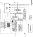
- FIG. 1 shows an example WHR hybrid power drive system 100 .
- the WHR hybrid power drive system 100 includes a WHR-motor/generator hybrid power drive (“WHR-MG drive”) 101 , a controller 102 , a heat exchanger 122 , a condenser 104 , a battery system 110 , and a motor 150 .
- the WHR hybrid power drive system 100 can be utilized in a vehicle, such as a hybrid vehicle. In such a hybrid vehicle, power to the output shaft of the vehicle can be provided by an engine 140 , or an electrical motor, such as the motor 150 .
- the WHR-MG drive 101 can recover thermal energy and convert the recovered thermal energy into electrical or mechanical energy. The electrical or mechanical energy can be provided to drive the vehicle.
- the WHR-MG drive 101 can include a WHR power unit 106 , which includes an expander 124 and a feed pump 126 .
- the WHR-MG drive 101 also includes a motor/generator 108 , and a mechanical linkage 116 .
- the WHR-MG drive 101 may optionally include a first decoupling device 118 , a second decoupling device 114 , a third decoupling device 120 , and auxiliary devices 112 .
- the expander 124 and the feed pump 126 are in fluid communication with the heat exchanger 122 and the condenser 104 .
- the expander 124 , the condenser 104 , the feed pump 126 , and the heat exchanger 122 form a Rankine cycle waste heat recovery system or an organic Rankine cycle if the working fluid is an organic high molecular mass fluid with a liquid-vapor phase change that is lower than the water-steam phase change.
- Rankine cycle working fluids organic and inorganic
- examples of Rankine cycle working fluids, organic and inorganic include GenetronTM R-245fa or SolsticeTM R1233zd(E) from Honeywell, TherminolTM, Dowtherm JTM from Dow Chemical Co., Fluorinol® from American Nickeloid, toluene, dodecane, isododecane, methylundecane, neopentane, neopentane, octane, water/methanol mixtures, or steam.
- the expander 124 is positioned downstream of the heat exchanger 122 , and receives a working fluid that has absorbed heat energy in the heat exchanger 122 .
- the heat exchanger 122 provides heat transfer from one or more heat sources in the vehicle to the working fluid.
- the heat sources can include, for example, exhaust gas produced by the engine 140 , heat generated at the brake-pads/rotors, and heat produced by the motor 150 or the engine 140 .
- the expander 124 can include a turbine, a piston, a screw, and the like, and can convert the motion of the working fluid into rotational motion of a WHR-MG drive shaft 130 .
- the condenser 104 is coupled downstream of the expander 124 , and provides cooling to the working fluid provided by the expander 124 .
- the output of the condenser 104 is coupled to the feed pump 126 , which, when activated, circulates the working fluid within the working fluid circuit.
- the feed pump 126 can be provided power from several sources.
- the feed pump 126 can be coupled to the WHR-MG drive shaft 130 , which is driven by the expander 124 .
- the feed pump 126 can be coupled to an output shaft 128 via the mechanical linkage 116 when the vehicle is running.
- the feed pump 126 can be driven by the motor/generator 108 also via the mechanical linkage 116 .
- the feed pump 126 could be coupled to a battery that provides power to operate the feed pump 126 .
- the motor/generator 108 can operate as a motor or a generator. When operating as a motor, the motor/generator 108 converts electrical energy received from the battery system 110 into rotational motion of a motor/generator drive shaft 132 . When operating as a generator, the motor/generator 108 converts rotational motion of the motor/generator drive shaft 132 into electrical energy, which is provided to the battery system 110 .
- the battery system 110 can provide power to a motor 150 , which can be coupled to the output shaft 128 , or another drive shaft, such as the final drive shaft, to provide motion to the vehicle.
- the WHR-MG drive 101 is coupled to the mechanical linkage 116 via the WHR-MG drive shaft 130 .
- the rotational energy imparted onto the WHR-MG drive shaft 130 by the expander 124 can drive the mechanical linkage 116 , which can include a clutch, or a similar device, that can selectively engage and disengage the WHR-MG drive shaft 130 from the output shaft 128 of the vehicle.
- the mechanical linkage 116 can selectively engage and disengage the output shaft 128 from the motor/generator drive shaft 132 , which is coupled to the motor/generator.
- the mechanical linkage 116 can independently couple any one of the WHR-MG drive shaft 130 and the motor/generator drive shaft 132 to the output shaft 128 .
- the mechanical linkage 116 can also couple the WHR-MG drive shaft 130 to the motor/generator drive shaft 132 , and decouple both these drive shafts from the output shaft 128 . This allows power transfer between the WHR power unit 106 and the motor/generator 108 .
- the feed pump 126 can be driven by the motor/generator drive shaft 132 . This can also allow pre-charging of the heat exchanger 122 with the working fluid.
- the WHR-MG drive 101 can optionally include the first decoupling device 118 , the second decoupling device 114 , and a third decoupling device 120 .
- the first decoupling device 118 is positioned between the WHR power unit 106 and the mechanical linkage 116
- the second decoupling device 114 is positioned between the mechanical linkage and the output shaft 128
- the third decoupling device 120 is positioned between the motor/generator 108 and the mechanical linkage 116 .
- the first, second, and third decoupling devices 118 , 114 , and 120 can be variable speed decoupling devices such as a planetary gear arrangement with a clutch, or a variable speed traction drive with traction fluid, or belt drive arrangement with movable sheaves, which can create a variable turning ratio.
- the decoupling devices can allow variable speed rotation of the shafts coupled thereto.
- the first decoupling device 118 can be configured to allow the WHR-MG drive shaft 130 to rotate at a speed that is different from a shaft coupling the first decoupling device to the mechanical linkage 116 .
- the second decoupling device 114 can be configured to allow the output shaft to rotate at a speed that is different from that of the shaft coupling the second decoupling device 114 to the mechanical linkage 116 .
- the third decoupling device 120 can be configured to allow the motor/generator drive shaft 132 to rotate at a speed that is different from that of a shaft coupling the third decoupling device 120 to the mechanical linkage 116 .
- Including the first, second, and the third decoupling devices 118 , 114 , and 120 can allow the WHR-MG drive shaft 130 , the output shaft 128 , and the motor/generator drive shaft 132 to rotate at different speeds. This can be beneficial in operating both the WHR power unit 106 and the motor/generator 108 at their respective and different optimal speeds.
- the WHR-MG drive 101 can optionally also include auxiliary devices 112 such as pumps and motors.
- the auxiliary devices 112 can be coupled to the mechanical linkage 116 , and can include pumps or motors that can provide lubrication and cooling to the WHR-MG drive 101 .
- the one or more auxiliary devices 112 can be coupled to the mechanical linkage 116 to receive power to pump or circulate lubricant and coolant to various components of the WHR-MG drive 101 such as the WHR power unit 106 , the motor/generator 108 , the mechanical linkage 116 , the optional first, second, and third decoupling devices 118 , 114 , and 120 .
- the controller 102 controls the operation of the WHR hybrid power drive system 100 .
- the controller 102 can include a processor, a microcontroller, an application specific integrated circuit, a field programmable program logic (FPGA), or any other circuit. While not shown, the controller can include or be coupled to a volatile memory, a non-volatile memory, data storage, input-output interface circuits, and user interface circuits.
- the controller 102 can be coupled to one or more sensors in the WHR hybrid power drive system 100 and one or more actuators and switches that can control the operation or change the configuration of one or more components of the system 100 .
- the controller 102 controls the operation of the WHR-MG drive 101 during startup of the vehicle.
- the WHR power unit 106 may not produce any power before the vehicle is running and generating heat. In such instances, the WHR power unit 106 may not be able to sustain the working fluid circuit.
- the controller 102 can provide external mechanical or electrical power to the WHR power unit 106 to operate the feed pump 126 .
- the controller 102 controls the motor/generator 108 to operate as a motor by drawing power from the battery system 110 and rotating the motor/generator drive shaft 132 .
- the controller 102 also controls the mechanical linkage 116 to mechanically link the motor/generator drive shaft 132 to the WHR-MG drive shaft 130 , which is coupled to the feed pump 126 .
- the mechanical energy generated by the motor/generator 108 is transferred to the feed pump 126 , which causes the working fluid to circulate in the working fluid circuit.
- the controller 102 can control the mechanical linkage 116 to instead couple the output shaft 128 to the WHR-MG drive shaft 130 , thereby transferring the mechanical power from the rotating output shaft 128 to the feed pump 126 .
- the controller 102 can initiate providing electric power to the feed pump 126 via a battery circuit (such as the battery system 110 ) to start the feed pump 126 .
- the controller 102 can maintain providing power to the WHR-MG drive shaft 130 until the WHR power unit 106 is self-sustaining.
- the WHR power unit 106 is able to convert thermal energy into mechanical energy (by the expander 124 ), that is sufficient to operate the feed pump 126 .
- the controller 102 disengages any electrical power provided to the feed pump 126 and engages the WHR-MG drive shaft 130 to the output shaft 128 or to the motor/generator drive shaft 132 , to transfer power generated by the WHR power unit 106 .
- the controller 102 can configure the mechanical linkage 116 such that the power generated by the WHR power unit 106 could be provided to either the output shaft 128 or to the motor/generator 108 .
- the controller 102 controls the mechanical linkage 116 to couple the WHR-MG drive shaft 130 to the output shaft 128 .
- the controller 102 controls the mechanical linkage 116 to couple the WHR-MG drive shaft 130 to the motor/generator drive shaft 132 , and controls the motor/generator 108 to operate as a generator.
- the motor/generator 108 converts the mechanical power generated by the WHR power unit 106 into electrical energy, which is provided to the battery system 110 .
- the controller 102 when the controller 102 detects the application of the brake, the controller 102 controls the mechanical linkage 116 to couple the output shaft 128 to the motor/generator drive shaft 132 .
- the controller 102 controls the mechanical linkage 116 to couple the output shaft 128 to the motor/generator drive shaft 132 .
- power that may have otherwise been lost during braking is converted into electrical energy to charge the battery system 110 .
- the controller 102 can control these decoupling devices such that the motor/generator 108 and the WHR power unit 106 can operate at optimal speeds. For example, when transferring power between the WHR power unit 106 and the output shaft 128 , the controller 102 controls one or both of the first decoupling device 118 and the second decoupling device 114 such that the speeds of rotations of the WHR-MG drive shaft 130 is different from the speed of rotation of the output shaft 128 . In particular, the controller 102 ensures that the speed of the WHR-MG drive shaft 130 is maintained at the optimal speed.
- the controller 102 controls one or both of the second decoupling device 114 and the third decoupling device 120 such that the speeds of rotation of the WHR-MG drive shaft 130 and the output shaft 128 are different. In particular, the controller 102 ensures that the speed of the motor/generator drive shaft 132 is maintained at the optimal speed.
- the controller 102 also can transfer power between the WHR power unit 106 and the motor/generator 108 .
- the controller 102 can control the first decoupling device 118 , the mechanical linkage 116 and the third decoupling device 120 to transfer power between the WHR-MG drive shaft 130 and the motor/generator drive shaft 132 .
- the controller 102 can configure the first decoupling device 118 and the third decoupling device 120 such that the optimal speeds of the WHR-MG drive shaft 130 and the motor/generator drive shaft 132 can be maintained.
- the controller 102 also can facilitate simultaneous transfer of power from one of the WHR-MG drive shaft 130 , the motor/generator drive shaft 132 , and the output shaft 128 to the other two of the WHR-MG drive shaft 130 , the motor/generator drive shaft 132 , and the output shaft 128 .
- the controller 102 can control the mechanical linkage 116 such that the power is transferred simultaneously and proportionally.
- the controller 102 can control the mechanical linkage 116 to transfer a portion of the power from the WHR-MG drive shaft 130 to the output shaft 128 and another portion to the motor/generator drive shaft 132 .
- the WHR-MG drive shaft 130 can simultaneously provide power to the engine and charge the battery system 110 .
- the controller 102 can control the mechanical linkage 116 to transfer power from the motor/generator drive shaft 132 simultaneously and proportionally to both the WHR-MG drive shaft 130 and to the output shaft 128 .
- the controller 102 can control the mechanical linkage 116 to transfer power from the output shaft 128 simultaneously and proportionally to both the WHR-MG drive shaft 130 and to the motor/generator drive shaft 132 .
- FIG. 2 shows a flow diagram of an example process 200 for controlling a WHR hybrid power system.
- the process 200 includes providing a waste heat recovery (WHR) hybrid power drive system comprising: a WHR power unit, a motor/generator, and a mechanical linkage coupled to a WHR drive shaft, a motor/generator drive shaft, and a output shaft ( 202 ).
- WHR waste heat recovery
- FIG. 1 shows a WHR-MG drive 101 that includes a WHR power unit 106 , a motor/generator 108 , and a mechanical linkage 116 .
- the WHR power unit 106 is structured to convert thermal energy, obtained from the heat exchanger 122 , into mechanical energy that manifests as rotation of the WHR-MG drive shaft 130 .
- the motor/generator 108 is structured to operate as a motor or a generator and includes a motor/generator drive shaft.
- the mechanical linkage 116 can link or delink the output shaft 128 from the WHR-MG drive shaft 130 or the motor/generator drive shaft 132 .
- the process 200 further includes controlling the mechanical linkage to link the output shaft to the WHR drive shaft, thereby causing the rotation of the WHR drive shaft to be transferred to a rotation of the output shaft ( 204 ). At least one example of this operation is discussed above in relation to FIG. 1 .
- the controller 102 can control the mechanical linkage 116 to couple the WHR-MG drive shaft 130 to the output shaft 128 .
- the controller 102 can control the mechanical linkage 116 when power is to be transferred from the WHR power unit 106 to the output shaft 128 .
- the process 200 also includes controlling the mechanical linkage to delink the output shaft from the WHR drive shaft ( 206 ). At least one example of this operation is discussed above in relation to FIG. 1 .
- the controller 102 can determine that the power from the output shaft 128 is transferred to the battery system 110 . Therefore, the controller 102 can control the mechanical linkage 116 to delink the output shaft 128 from the WHR-MG drive shaft 130 .
- the process 200 further includes controlling the mechanical linkage to link the output shaft to the motor/generator drive shaft, thereby causing a rotation of the output shaft to be transferred to a rotation of the motor/generator drive shaft ( 208 ).
- the controller 102 after controlling the mechanical linkage 116 to delink the output shaft 128 from the WHR-MG drive shaft 130 , can control the mechanical linkage 116 to link the output shaft 128 to the motor/generator drive shaft 132 . Therefore, the rotation of the output shaft 128 will be transferred to the rotation of the motor/generator drive shaft 132 .
- the controller 102 also can control the motor/generator 108 to operate as a generator, thereby causing the mechanical energy provided to the motor/generator 108 by the rotation of the motor/generator drive shaft 132 into electrical energy, which can be provided to the battery system 110 .
- the term “coupled” means the joining of two members directly or indirectly to one another. Such joining may be stationary or moveable in nature. Such joining may be achieved with the two members or the two members and any additional intermediate members being integrally formed as a single unitary body with one another or with the two members or the two members and any additional intermediate members being attached to one another. Such joining may be permanent in nature or may be removable or releasable in nature.
- inventive embodiments are presented by way of example only and that, within the scope of the appended claims and equivalents thereto, inventive embodiments may be practiced otherwise than as specifically described and claimed.
- inventive embodiments of the present disclosure are directed to each individual feature, system, article, material, kit, and/or method described herein.
- the technology described herein may be embodied as a method, of which at least one example has been provided.
- the acts performed as part of the method may be ordered in any suitable way unless otherwise specifically noted. Accordingly, embodiments may be constructed in which acts are performed in an order different than illustrated, which may include performing some acts simultaneously, even though shown as sequential acts in illustrative embodiments.
Landscapes
- Engineering & Computer Science (AREA)
- Mechanical Engineering (AREA)
- Chemical & Material Sciences (AREA)
- Combustion & Propulsion (AREA)
- Transportation (AREA)
- General Engineering & Computer Science (AREA)
- Automation & Control Theory (AREA)
- Electric Propulsion And Braking For Vehicles (AREA)
Abstract
Description
Claims (11)
Priority Applications (2)
| Application Number | Priority Date | Filing Date | Title |
|---|---|---|---|
| US15/909,578 US11001250B2 (en) | 2018-03-01 | 2018-03-01 | Waste heat recovery hybrid power drive |
| US17/229,438 US11820359B2 (en) | 2018-03-01 | 2021-04-13 | Waste heat recovery hybrid power drive |
Applications Claiming Priority (1)
| Application Number | Priority Date | Filing Date | Title |
|---|---|---|---|
| US15/909,578 US11001250B2 (en) | 2018-03-01 | 2018-03-01 | Waste heat recovery hybrid power drive |
Related Child Applications (1)
| Application Number | Title | Priority Date | Filing Date |
|---|---|---|---|
| US17/229,438 Division US11820359B2 (en) | 2018-03-01 | 2021-04-13 | Waste heat recovery hybrid power drive |
Publications (2)
| Publication Number | Publication Date |
|---|---|
| US20190270442A1 US20190270442A1 (en) | 2019-09-05 |
| US11001250B2 true US11001250B2 (en) | 2021-05-11 |
Family
ID=67768437
Family Applications (2)
| Application Number | Title | Priority Date | Filing Date |
|---|---|---|---|
| US15/909,578 Active 2039-06-23 US11001250B2 (en) | 2018-03-01 | 2018-03-01 | Waste heat recovery hybrid power drive |
| US17/229,438 Active 2038-05-04 US11820359B2 (en) | 2018-03-01 | 2021-04-13 | Waste heat recovery hybrid power drive |
Family Applications After (1)
| Application Number | Title | Priority Date | Filing Date |
|---|---|---|---|
| US17/229,438 Active 2038-05-04 US11820359B2 (en) | 2018-03-01 | 2021-04-13 | Waste heat recovery hybrid power drive |
Country Status (1)
| Country | Link |
|---|---|
| US (2) | US11001250B2 (en) |
Cited By (2)
| Publication number | Priority date | Publication date | Assignee | Title |
|---|---|---|---|---|
| US20210300328A1 (en) * | 2018-03-01 | 2021-09-30 | Cummins Inc. | Waste heat recovery hybrid power drive |
| US20240034165A1 (en) * | 2022-07-27 | 2024-02-01 | Saudi Arabian Oil Company | Methods of charging a hybrid vehicle battery |
Families Citing this family (1)
| Publication number | Priority date | Publication date | Assignee | Title |
|---|---|---|---|---|
| WO2019168927A1 (en) * | 2018-03-01 | 2019-09-06 | Cummins Inc. | Waste heat recovery hybrid power drive |
Citations (23)
| Publication number | Priority date | Publication date | Assignee | Title |
|---|---|---|---|---|
| US4148192A (en) * | 1977-11-23 | 1979-04-10 | Cummings Troy A | Internal combustion electric power hybrid power plant |
| US6450283B1 (en) | 2000-11-27 | 2002-09-17 | Michael Blake Taggett | Waste heat conversion system |
| US7056251B2 (en) * | 2000-10-10 | 2006-06-06 | Honda Giken Kogyo Kabushiki Kaisha | Hybrid vehicle |
| US7520133B2 (en) * | 2002-12-19 | 2009-04-21 | Bayerische Motoren Werke Aktiengesellschaft | Thermodynamic engine |
| US8141360B1 (en) * | 2005-10-18 | 2012-03-27 | Florida Turbine Technologies, Inc. | Hybrid gas turbine and internal combustion engine |
| US20130056992A1 (en) | 2010-03-24 | 2013-03-07 | Sanden Corporation | Waste heat utilization system for internal combustion engine, and motor-generator device for use in the system |
| US8739531B2 (en) * | 2009-01-13 | 2014-06-03 | Avl Powertrain Engineering, Inc. | Hybrid power plant with waste heat recovery system |
| US8881523B2 (en) * | 2008-08-26 | 2014-11-11 | Sanden Corporation | Waste heat utilization device for internal combustion engine |
| WO2015197087A1 (en) | 2014-06-26 | 2015-12-30 | Volvo Truck Corporation | Internal combustion engine system with heat recovery |
| US9470115B2 (en) * | 2010-08-11 | 2016-10-18 | Cummins Intellectual Property, Inc. | Split radiator design for heat rejection optimization for a waste heat recovery system |
| US20160326914A1 (en) | 2015-05-05 | 2016-11-10 | Cummins, Inc. | Waste heat recovery hybrid power drive |
| US20170058745A1 (en) | 2015-08-24 | 2017-03-02 | Hyundai Motor Company | Recovered energy transfer apparatus of waste heat recovery system |
| US9777602B2 (en) * | 2007-03-02 | 2017-10-03 | Victor Juchymenko | Supplementary thermal energy transfer in thermal energy recovery systems |
| US9810129B2 (en) * | 2016-03-08 | 2017-11-07 | Toyota Motor Engineering & Manufacturing North America, Inc. | Integrated waste heat recovery and motor assisted turbocharger system |
| US9862262B2 (en) * | 2015-07-30 | 2018-01-09 | Ford Global Technologies, Llc | Hybrid vehicle powertrain |
| US10174714B2 (en) * | 2015-07-25 | 2019-01-08 | Man Truck & Bus Ag | Apparatus and method for combined electrical and mechanical utilization of the energy of an expansion machine |
| US10279676B2 (en) * | 2017-03-07 | 2019-05-07 | Toyota Motor Engineering & Manufacturing North America, Inc. | Hybrid vehicle with in wheel motor and rankine cycle system |
| US10427528B2 (en) * | 2015-05-13 | 2019-10-01 | Mahle International Gmbh | Vehicle |
| US10787935B2 (en) * | 2014-12-05 | 2020-09-29 | Scania Cv Ab | Cooling arrangement for a WHR-system |
| US10815931B2 (en) * | 2017-12-14 | 2020-10-27 | Cummins Inc. | Waste heat recovery system with low temperature heat exchanger |
| US10830121B2 (en) * | 2016-01-15 | 2020-11-10 | Scania Cv Ab | Cooling system for a combustion engine and a WHR system |
| US10871098B2 (en) * | 2015-08-06 | 2020-12-22 | Samsung Heavy Ind. Co., Ltd. | Thermoelectric generation apparatus, heat generation apparatus for fuel storage tanks, and waste heat recovery system |
| US10876497B2 (en) * | 2017-08-18 | 2020-12-29 | Rolls-Royce North American Technologies Inc. | Method for fast thermalization and thermal management operation optimization |
Family Cites Families (16)
| Publication number | Priority date | Publication date | Assignee | Title |
|---|---|---|---|---|
| US6931850B2 (en) * | 2003-09-10 | 2005-08-23 | The Regents Of The Univesity Of California | Exhaust gas driven generation of electric power and altitude compensation in vehicles including hybrid electric vehicles |
| US20060046894A1 (en) * | 2004-08-09 | 2006-03-02 | Kyle Ronald L | Hybrid vehicle with exhaust powered turbo generator |
| JP2012187961A (en) * | 2011-03-09 | 2012-10-04 | Ygk:Kk | Hybrid vehicle |
| US9500124B2 (en) * | 2014-11-13 | 2016-11-22 | Caterpillar Inc. | Hybrid powertrain and method for operating same |
| CN107849945B (en) * | 2015-04-24 | 2020-02-14 | 诺沃皮尼奥内技术股份有限公司 | Compressor driven by ORC waste heat recovery unit and control method |
| RU2699204C1 (en) * | 2015-11-09 | 2019-09-03 | Ниссан Мотор Ко., Лтд. | Braking/driving force control method and brake/driving force control device |
| ITUB20160955A1 (en) * | 2016-02-22 | 2017-08-22 | Nuovo Pignone Tecnologie Srl | CYCLE IN CASCAME OF RECOVERY OF CASCAME THERMAL AND METHOD |
| US10094246B2 (en) * | 2016-11-01 | 2018-10-09 | Ford Global Technologies, Llc | Waste heat recovery for power generation and engine warm up |
| JP6760488B2 (en) * | 2017-04-04 | 2020-09-23 | 日産自動車株式会社 | Vehicle control method and vehicle control device |
| DE102017120615A1 (en) * | 2017-09-07 | 2019-03-07 | Volkswagen Aktiengesellschaft | Motor vehicle with a cooling system |
| JP6919720B2 (en) * | 2017-12-15 | 2021-08-18 | 日産自動車株式会社 | Hybrid vehicle control method and control device |
| DE102017011844A1 (en) * | 2017-12-21 | 2019-06-27 | Daimler Ag | Arrangement for converting thermal energy from heat loss of an internal combustion engine |
| DE102018202919A1 (en) * | 2018-02-27 | 2019-11-14 | Robert Bosch Gmbh | Control circuit for waste heat recovery systems |
| US11001250B2 (en) * | 2018-03-01 | 2021-05-11 | Cummins Inc. | Waste heat recovery hybrid power drive |
| DE102019100503A1 (en) * | 2019-01-10 | 2020-07-16 | Bayerische Motoren Werke Aktiengesellschaft | Control unit and method for operating a hybrid drive with a double clutch transmission |
| WO2020190344A2 (en) * | 2019-03-18 | 2020-09-24 | United Technologies Advanced Projects Inc. | Architectures for hybrid-electric propulsion |
-
2018
- 2018-03-01 US US15/909,578 patent/US11001250B2/en active Active
-
2021
- 2021-04-13 US US17/229,438 patent/US11820359B2/en active Active
Patent Citations (24)
| Publication number | Priority date | Publication date | Assignee | Title |
|---|---|---|---|---|
| US4148192A (en) * | 1977-11-23 | 1979-04-10 | Cummings Troy A | Internal combustion electric power hybrid power plant |
| US7056251B2 (en) * | 2000-10-10 | 2006-06-06 | Honda Giken Kogyo Kabushiki Kaisha | Hybrid vehicle |
| US6450283B1 (en) | 2000-11-27 | 2002-09-17 | Michael Blake Taggett | Waste heat conversion system |
| US7520133B2 (en) * | 2002-12-19 | 2009-04-21 | Bayerische Motoren Werke Aktiengesellschaft | Thermodynamic engine |
| US8141360B1 (en) * | 2005-10-18 | 2012-03-27 | Florida Turbine Technologies, Inc. | Hybrid gas turbine and internal combustion engine |
| US9777602B2 (en) * | 2007-03-02 | 2017-10-03 | Victor Juchymenko | Supplementary thermal energy transfer in thermal energy recovery systems |
| US8881523B2 (en) * | 2008-08-26 | 2014-11-11 | Sanden Corporation | Waste heat utilization device for internal combustion engine |
| US8739531B2 (en) * | 2009-01-13 | 2014-06-03 | Avl Powertrain Engineering, Inc. | Hybrid power plant with waste heat recovery system |
| US20130056992A1 (en) | 2010-03-24 | 2013-03-07 | Sanden Corporation | Waste heat utilization system for internal combustion engine, and motor-generator device for use in the system |
| US9470115B2 (en) * | 2010-08-11 | 2016-10-18 | Cummins Intellectual Property, Inc. | Split radiator design for heat rejection optimization for a waste heat recovery system |
| WO2015197087A1 (en) | 2014-06-26 | 2015-12-30 | Volvo Truck Corporation | Internal combustion engine system with heat recovery |
| US10787935B2 (en) * | 2014-12-05 | 2020-09-29 | Scania Cv Ab | Cooling arrangement for a WHR-system |
| US20160326914A1 (en) | 2015-05-05 | 2016-11-10 | Cummins, Inc. | Waste heat recovery hybrid power drive |
| US10427528B2 (en) * | 2015-05-13 | 2019-10-01 | Mahle International Gmbh | Vehicle |
| US10174714B2 (en) * | 2015-07-25 | 2019-01-08 | Man Truck & Bus Ag | Apparatus and method for combined electrical and mechanical utilization of the energy of an expansion machine |
| US9862262B2 (en) * | 2015-07-30 | 2018-01-09 | Ford Global Technologies, Llc | Hybrid vehicle powertrain |
| US10871098B2 (en) * | 2015-08-06 | 2020-12-22 | Samsung Heavy Ind. Co., Ltd. | Thermoelectric generation apparatus, heat generation apparatus for fuel storage tanks, and waste heat recovery system |
| US9835072B2 (en) * | 2015-08-24 | 2017-12-05 | Hyundai Motor Company | Recovered energy transfer apparatus of waste heat recovery system |
| US20170058745A1 (en) | 2015-08-24 | 2017-03-02 | Hyundai Motor Company | Recovered energy transfer apparatus of waste heat recovery system |
| US10830121B2 (en) * | 2016-01-15 | 2020-11-10 | Scania Cv Ab | Cooling system for a combustion engine and a WHR system |
| US9810129B2 (en) * | 2016-03-08 | 2017-11-07 | Toyota Motor Engineering & Manufacturing North America, Inc. | Integrated waste heat recovery and motor assisted turbocharger system |
| US10279676B2 (en) * | 2017-03-07 | 2019-05-07 | Toyota Motor Engineering & Manufacturing North America, Inc. | Hybrid vehicle with in wheel motor and rankine cycle system |
| US10876497B2 (en) * | 2017-08-18 | 2020-12-29 | Rolls-Royce North American Technologies Inc. | Method for fast thermalization and thermal management operation optimization |
| US10815931B2 (en) * | 2017-12-14 | 2020-10-27 | Cummins Inc. | Waste heat recovery system with low temperature heat exchanger |
Cited By (3)
| Publication number | Priority date | Publication date | Assignee | Title |
|---|---|---|---|---|
| US20210300328A1 (en) * | 2018-03-01 | 2021-09-30 | Cummins Inc. | Waste heat recovery hybrid power drive |
| US11820359B2 (en) * | 2018-03-01 | 2023-11-21 | Cummins Inc. | Waste heat recovery hybrid power drive |
| US20240034165A1 (en) * | 2022-07-27 | 2024-02-01 | Saudi Arabian Oil Company | Methods of charging a hybrid vehicle battery |
Also Published As
| Publication number | Publication date |
|---|---|
| US20210300328A1 (en) | 2021-09-30 |
| US20190270442A1 (en) | 2019-09-05 |
| US11820359B2 (en) | 2023-11-21 |
Similar Documents
| Publication | Publication Date | Title |
|---|---|---|
| US11820359B2 (en) | Waste heat recovery hybrid power drive | |
| US9890664B2 (en) | Integrated power, cooling, and heating apparatus utilizing waste heat recovery | |
| US9810129B2 (en) | Integrated waste heat recovery and motor assisted turbocharger system | |
| JP6275656B2 (en) | Waste heat utilization equipment for automobiles | |
| KR102423941B1 (en) | Waste heat recovery system | |
| US7637108B1 (en) | Power compounder | |
| US20080092540A1 (en) | Engine apparatus with heat recovery system and relative heat recovery method | |
| WO2011058832A1 (en) | Engine waste heat recovery power-generating turbo system and reciprocating engine system provided therewith | |
| US20100192574A1 (en) | Power compounder | |
| US5636509A (en) | Flywheel engine improvements | |
| US20140352301A1 (en) | Motor vehicle with a couplable waste heat recovery system | |
| CN106164419A (en) | ORC system electromotor close down after stress management | |
| JP2015511673A (en) | Flywheel mechanical energy derived from engine exhaust heat | |
| JP6236085B2 (en) | Supercharger for an internal combustion engine | |
| US12157369B2 (en) | Transmission-mounted combined energy recovery drive | |
| US11833902B2 (en) | Waste heat recovery hybrid power drive | |
| US9835072B2 (en) | Recovered energy transfer apparatus of waste heat recovery system | |
| CN106351766B (en) | Recovered energy transmission device of waste heat recovery system | |
| CN108868925B (en) | Expansion device for recovering waste heat and waste heat recovery system including the same | |
| US12040689B2 (en) | Electric vehicle with energy recovery system | |
| KR101966466B1 (en) | Turbine generating device and System of recycling exhaust heat from internal combustion engine having the same | |
| Narula et al. | Waste heat recovery hybrid power drive | |
| WO2017096280A2 (en) | Oil free organic rankine cycle roots expander | |
| KR101578482B1 (en) | Electro Water Pump for Co-generation System | |
| CN105291808A (en) | Hybrid power transmission integration system and control method thereof |
Legal Events
| Date | Code | Title | Description |
|---|---|---|---|
| FEPP | Fee payment procedure |
Free format text: ENTITY STATUS SET TO UNDISCOUNTED (ORIGINAL EVENT CODE: BIG.); ENTITY STATUS OF PATENT OWNER: LARGE ENTITY |
|
| AS | Assignment |
Owner name: UNITED STATES DEPARTMENT OF ENERGY, DISTRICT OF CO Free format text: CONFIRMATORY LICENSE;ASSIGNOR:CUMMINS, INC. D/B/A CUMMINS TECHNICAL CENTER;REEL/FRAME:047479/0952 Effective date: 20180416 Owner name: UNITED STATES DEPARTMENT OF ENERGY, DISTRICT OF COLUMBIA Free format text: CONFIRMATORY LICENSE;ASSIGNOR:CUMMINS, INC. D/B/A CUMMINS TECHNICAL CENTER;REEL/FRAME:047479/0952 Effective date: 20180416 |
|
| STPP | Information on status: patent application and granting procedure in general |
Free format text: NON FINAL ACTION MAILED |
|
| STPP | Information on status: patent application and granting procedure in general |
Free format text: RESPONSE TO NON-FINAL OFFICE ACTION ENTERED AND FORWARDED TO EXAMINER |
|
| STPP | Information on status: patent application and granting procedure in general |
Free format text: RESPONSE TO NON-FINAL OFFICE ACTION ENTERED AND FORWARDED TO EXAMINER |
|
| STPP | Information on status: patent application and granting procedure in general |
Free format text: NOTICE OF ALLOWANCE MAILED -- APPLICATION RECEIVED IN OFFICE OF PUBLICATIONS |
|
| STPP | Information on status: patent application and granting procedure in general |
Free format text: PUBLICATIONS -- ISSUE FEE PAYMENT RECEIVED |
|
| STPP | Information on status: patent application and granting procedure in general |
Free format text: PUBLICATIONS -- ISSUE FEE PAYMENT VERIFIED |
|
| AS | Assignment |
Owner name: CUMMINS INC., INDIANA Free format text: ASSIGNMENT OF ASSIGNORS INTEREST;ASSIGNORS:NARULA, MANIK;ERNST, TIMOTHY C.;RUTH, MICHAEL J.;AND OTHERS;SIGNING DATES FROM 20180305 TO 20180406;REEL/FRAME:055887/0270 |
|
| STCF | Information on status: patent grant |
Free format text: PATENTED CASE |
|
| MAFP | Maintenance fee payment |
Free format text: PAYMENT OF MAINTENANCE FEE, 4TH YEAR, LARGE ENTITY (ORIGINAL EVENT CODE: M1551); ENTITY STATUS OF PATENT OWNER: LARGE ENTITY Year of fee payment: 4 |