EP3453101B1 - Verfahren zur herstellung eines polgehäuses - Google Patents
Verfahren zur herstellung eines polgehäuses Download PDFInfo
- Publication number
- EP3453101B1 EP3453101B1 EP17721558.9A EP17721558A EP3453101B1 EP 3453101 B1 EP3453101 B1 EP 3453101B1 EP 17721558 A EP17721558 A EP 17721558A EP 3453101 B1 EP3453101 B1 EP 3453101B1
- Authority
- EP
- European Patent Office
- Prior art keywords
- tube
- pole
- jacket
- cover
- fed
- Prior art date
- Legal status (The legal status is an assumption and is not a legal conclusion. Google has not performed a legal analysis and makes no representation as to the accuracy of the status listed.)
- Active
Links
Images


Classifications
-
- H—ELECTRICITY
- H02—GENERATION; CONVERSION OR DISTRIBUTION OF ELECTRIC POWER
- H02K—DYNAMO-ELECTRIC MACHINES
- H02K15/00—Processes or apparatus specially adapted for manufacturing, assembling, maintaining or repairing of dynamo-electric machines
- H02K15/02—Processes or apparatus specially adapted for manufacturing, assembling, maintaining or repairing of dynamo-electric machines of stator or rotor bodies
- H02K15/03—Processes or apparatus specially adapted for manufacturing, assembling, maintaining or repairing of dynamo-electric machines of stator or rotor bodies having permanent magnets
-
- H—ELECTRICITY
- H02—GENERATION; CONVERSION OR DISTRIBUTION OF ELECTRIC POWER
- H02K—DYNAMO-ELECTRIC MACHINES
- H02K15/00—Processes or apparatus specially adapted for manufacturing, assembling, maintaining or repairing of dynamo-electric machines
- H02K15/14—Casings; Enclosures; Supports
-
- H—ELECTRICITY
- H02—GENERATION; CONVERSION OR DISTRIBUTION OF ELECTRIC POWER
- H02K—DYNAMO-ELECTRIC MACHINES
- H02K5/00—Casings; Enclosures; Supports
- H02K5/04—Casings or enclosures characterised by the shape, form or construction thereof
-
- H—ELECTRICITY
- H02—GENERATION; CONVERSION OR DISTRIBUTION OF ELECTRIC POWER
- H02K—DYNAMO-ELECTRIC MACHINES
- H02K5/00—Casings; Enclosures; Supports
- H02K5/04—Casings or enclosures characterised by the shape, form or construction thereof
- H02K5/10—Casings or enclosures characterised by the shape, form or construction thereof with arrangements for protection from ingress, e.g. water or fingers
-
- H—ELECTRICITY
- H02—GENERATION; CONVERSION OR DISTRIBUTION OF ELECTRIC POWER
- H02K—DYNAMO-ELECTRIC MACHINES
- H02K15/00—Processes or apparatus specially adapted for manufacturing, assembling, maintaining or repairing of dynamo-electric machines
- H02K15/06—Embedding prefabricated windings in the machines
- H02K15/062—Windings in slots; Salient pole windings
Definitions
- the invention relates to a method for producing a pole housing for an electric motor.
- the invention also relates to a pole housing produced by such a method and an electric motor equipped with such a pole housing.
- Electric motors in particular compact motors, often have what is known as a pole housing, in which permanent magnets, which form the stator of the electric motor, and the rotor (rotor or armature) are inserted on the inside wall.
- Pole housings are often manufactured using the so-called deep-drawing process.
- the pole housing can also be manufactured in classic tube production, in which a tube is shaped into the later pole tube shape, for example by stress-relieving annealing and repeated tube drawing.
- the pipe can then be cut to length in a special machine, for example.
- the end faces of the pipe are then ground.
- the pipe is galvanized as bulk material to protect it from corrosion. Disadvantages here are in particular the relatively large number of individual manufacturing steps, subsequent galvanizing and the costly semi-finished product in the form of the tube.
- a method for producing a pipe is known in which the pipe is formed from a substantially flat metal sheet. The longitudinal edges of the sheet are connected to one another by positively interlocking elements.
- From the DE 100 23 313 A1 discloses a method for fastening a stator in a housing, in which the housing is made from a sheet metal strip by means of bending.
- the end edges of the sheet metal strip that touch each other after the bending process interlock to form a joint gap, the internal diameter of the housing being greater than the external diameter of the stator.
- WO 2012/113432 A3 describes a method for producing a gas- and liquid-tight pole housing.
- a tube jacket surface made from a pre-galvanized sheet metal material is joined to a pole tube by means of a material-locking laser welding process.
- a bearing plate is firmly bonded to an end face of the pole tube.
- the DE 10 2011 012 317 A1 discloses a method for producing a gas- and liquid-tight pole housing. According to the known method, a tube jacket surface made from a pre-galvanized sheet metal material is joined to a cylindrical pole tube by means of a material-locking laser welding process.
- the U.S. 5,426,337 A describes a pole housing for an electric motor, which is made from a rectangular sheet metal material.
- the sheet metal material is formed into a cylindrical pipe casing, the pipe longitudinal or end edges of the pipe casing running in the longitudinal direction of the pipe being provided with curved shaped contours.
- the mutually facing ones grip Form contours of the pipe longitudinal edges form-fitting into one another.
- a cover is then attached to the end of the pole tube by means of crimping.
- the invention is based on the object of specifying a method which is particularly suitable for producing a pole housing.
- the method is intended to enable the pole housing to be produced in a simple, time-saving and cost-effective manner.
- the invention is also based on the object of specifying a pole housing produced by such a method and an electric motor provided with such a pole housing.
- a pipe jacket surface consisting of a sheet metal material is first provided.
- the preferably pre-galvanized sheet metal material is unrolled and straightened, for example, from a sheet metal roll (sheet metal coil) and fed to a punching device for cutting off the approximately rectangular pipe jacket.
- the pipe jacket made of the galvanized sheet material is then shaped into a cylindrical pole tube in such a way that the pipe longitudinal or end edges of the pipe jacket (jacket longitudinal edges) which run in the longitudinal direction of the pipe face one another. Thereafter, these longitudinal edges of the pipe jacket surface are connected to one another to form a circumferentially closed pole pipe.
- a cover is attached to an end of the pipe in a form-fitting and / or force-fitting manner. This means that no additional welding equipment is required the fastening of the lid is required, which saves tool costs. This is advantageously carried over to the production costs of the pole housing.
- the cover which serves in particular as a position shield of the pole housing for an electric motor, is preferably provided as a prefabricated part. This enables the provision of a wide variety of bearing caps, while this flexibility is not given with a deep-drawn pole housing.
- the tube jacket is first fed to a bending device for preforming (rolling, bending, clinching) into an approximately round or cylindrical shape and then to a calibration device for creating the circular shape of the cylindrical pole tube.
- the desired inner and outer diameter of the pole tube can be set in the calibration device. This ensures a particularly high level of manufacturing accuracy, which is advantageously transferred with regard to the production of large numbers of the pole housing.
- the longitudinal edges of the pipe jacket are closed on the circumference in a next process step Pole tube connected to one another by a material bond.
- the pipe jacket bent in a rotationally symmetrical manner e.g. cylindrical with or without a beveled inlet
- a welding device which integrally connects the longitudinal edges of the galvanized pipe jacket with one another by means of a laser weld seam.
- a laser weld seam ensures a reliable and, in particular, fluid-impermeable joint edge connection. This is also preferably material-saving due to the overlapping of the longitudinal edges of the casing avoided as a result.
- Another advantage of the laser-welded end edge connection is the comparatively low, concentrated energy input into the pole tube and thus less thermal distortion. As a result, much closer tolerances of the pole tube can be produced and adhered to quickly and easily.
- connection is also not made selectively, as in the case of crimping, but rather uniformly along the longitudinal edges of the pole tube.
- the laser weld seam prevents geometric and structural unevenness and ensures the production of a pole tube that is particularly impermeable to liquids and gases.
- the pole tube welded on the jacket side is fed in a subsequent process step to a punching and / or bending device for bending a number of fastening tabs distributed around the circumference of a tube end.
- a punching and / or bending device for bending a number of fastening tabs distributed around the circumference of a tube end.
- These can be screw tabs or eyelets and / or brush crimping hooks.
- the fastening tabs are arranged on the end of the tube opposite the cover.
- the cover is fastened to the pole tube by plastic deformation of the tube end, in particular by means of caulking or crimping. This ensures particularly simple and inexpensive manufacture of the pole housing.
- connection or the fastening point between the cover and the pole tube is impermeable to fluid, so that a fluid-tight pole housing is provided.
- a preferably circumferential, stepped contour with a radial bearing surface for supporting the cover and with an axial annular wall section is introduced on the inner wall side.
- the stepped contour which is produced, for example, by means of a cutting or forming process, ensures that the cover is precisely positioned on the pole tube during assembly of the pole housing.
- the pole tube is fed to a stamp device for producing the step contour.
- the stamping device then impresses the step contour on the tube end on the cover side by means of a forming process. A particularly simple production of the step contour is thereby achieved.
- the axial annular wall section is deformed radially inward while holding the cover.
- the cover is first inserted into the stepped contour of the tube end.
- the axial height of the annular wall section is preferably greater than the axial height of the cover, so that the annular wall section at least partially protrudes beyond the cover when it is seated.
- This protruding area of the annular wall section is then reshaped radially inward, in particular bent or stamped, in particular by means of caulking or crimping.
- the cover is overlapped at least in sections by the bent-over annular wall section, so that an operationally reliable and fluid-tight mounting of the cover on the pole tube is ensured.
- the pole housing produced according to the method described above has particularly low production costs. This is carried over particularly advantageously to applications in the automotive industry, since the required high numbers of pieces can thus be produced particularly easily and inexpensively.
- a pre-galvanized sheet metal material is used compared to conventional methods, which is processed in a stamping and bending machine.
- the tube jacket surfaces (blanks) are first unrolled from the sheet metal coil, punched and bent (clinched) into a tube with a round cross-section in a forming station.
- the laser welding creates a solid and liquid-impermeable connection of the longitudinal edges of the jacket.
- the cover as a bearing plate is attached to the pole tube in a form-fitting and / or force-fitting manner by means of caulking or crimping the stepped contour.
- the cover as a bearing plate is attached to the pole tube in a form-fitting and / or force-fitting manner by means of caulking or crimping the stepped contour.
- the pole housing produced from a pre-galvanized material by a stamping and bending process is therefore particularly suitable for an electric motor which is provided, for example, as an actuator for an adjustment part of a motor vehicle.
- the pole tube 2 shown is made from a preferably galvanized sheet steel.
- the pipe jacket surface or the pipe jacket 4 of the pole tube 2 forms two opposite jacket longitudinal edges 6 running in the pipe longitudinal direction L, which are guided against one another, with a radial pipe gap 8 running axially between the two mangling longitudinal edges 6 of the pipe jacket 4.
- the pipe gap 8 and thus the longitudinal edges 6 facing one another are connected to one another in a materially bonded and liquid and / or gas-impermeable manner to form the circumferentially closed pole tube 2.
- One of the end faces or tube ends 12 a of the pole tube 2 is closed with a (bearing) cover 14.
- This serves as a bearing plate to provide a bearing that accommodates the shaft of an electric motor or its rotor.
- This provides a pole housing 16 of the electric motor that is closed at least on one side in a simple and flexible manner.
- permanent magnets can be attached beforehand as the stator of the electric motor.
- the electric motor can be used in particular as a compact actuator for an adjustment part of a motor vehicle, for example for a seat adjustment or a window lifter.
- Fig. 1 schematically illustrates the process sequence for the production of pole housings 16 from a galvanized material.
- the starting point is a sheet metal roll (sheet metal coil) 18 with a sheet metal already pre-galvanized and rolled up in several layers with a sheet thickness of, for example, 1.0 mm to 3.0 mm.
- the sheet metal coil 18 is unwound and continuously straightened in a first process step in a straightening apparatus 20, the respectively straightened sheet metal section always being part of the quasi-endless sheet metal strip of the sheet metal roll 18.
- the bandwidth of the sheet metal roller 18 essentially corresponds to the later pole tube length.
- the size of the required pipe jacket 4 is cut to length from the sheet metal roll 18 by means of a punching device 22.
- the sheet metal sections produced in this way already correspond to the sheet metal or tube shells 4 of the later pole tubes 2.
- the sheet metal jacket 4 or the sheet metal piece cut to length is then bent at least roughly into the later cylindrical shape in a bending device 24.
- the punching device 22 and the bending device 24 are suitably part of a combined bending and punching machine.
- an automatic straightener or a calibration device 26 is used to precisely shape the sheet metal jackets 4 into the ideal, circular cylindrical shape.
- the pipe contour is calibrated, that is, the inside and outside diameter, of the later pole tube 2 to the practically optimal round shape.
- laser welding takes place by means of a welding device 28 along the aligned longitudinal longitudinal edges 6 of the pipe jacket 4 from the sheet metal jacket bent in a rotationally symmetrical manner (e.g. cylindrical with or without a beveled inlet).
- a welding device 28 along the aligned longitudinal longitudinal edges 6 of the pipe jacket 4 from the sheet metal jacket bent in a rotationally symmetrical manner (e.g. cylindrical with or without a beveled inlet).
- the raw jacket 4 is kept in its calibrated, cylindrical ideal shape by corresponding supporting forces F acting at several points on the raw jacket 4.
- screw-on points are formed, again by means of an automatic bending or bending / punching machine not shown in detail and / or brush crimping hooks on the end face (tube end) 12b of the welded pole tube 2 opposite the end face 12a, in that corresponding fastening tabs 30 or the like are bent from the circumferential surface 4 at exposed points.
- a stepped contour 32 is introduced into the tube end 12a, that is, on the end face of the pole tube 2 opposite the fastening tabs 30.
- the pole tube 2 is placed in a stamping device 34 which, for example, can also be part of the automatic bending and punching device comprising the bending device 24 and punching device 22.
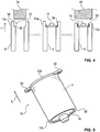
- the stepped contour 32 is stamped into the inner wall of the pipe end 12a by the stamping device 32, forming a radial bearing surface 36 and an axial annular wall section 38 ( Fig. 4 Left).
- the bearing cover 14 is placed on the support surface 36 so that it is essentially completely seated within the annular wall section 38. Finally, the bearing cover 14 is fastened to the pole tube 2 by a crimping device 40.
- the areas of the annular wall section 38 protruding from the bearing cover 14 are reshaped radially inward ( Fig. 4 right).
- the reshaped (bent, stamped) annular wall section 38 ′ thus overlaps the bearing cover 14 at least in sections. This results in a fluid-tight fastening of the bearing cover 14 on the pole tube 2.
- the end shield 14 is provided here, for example, as a finished part or a semi-finished product.
Landscapes
- Engineering & Computer Science (AREA)
- Power Engineering (AREA)
- Manufacturing & Machinery (AREA)
- Manufacture Of Motors, Generators (AREA)
- Laser Beam Processing (AREA)
- Iron Core Of Rotating Electric Machines (AREA)
- Bending Of Plates, Rods, And Pipes (AREA)
- Motor Or Generator Frames (AREA)
Description
- Die Erfindung betrifft ein Verfahren zur Herstellung eines Polgehäuses für einen Elektromotor. Die Erfindung betrifft weiterhin ein nach einem derartigen Verfahren hergestelltes Polgehäuse sowie einen mit einem solchen Polgehäuse ausgestatteten Elektromotor.
- Elektromotoren, insbesondere Kompaktmotoren, weisen häufig ein sogenanntes Polgehäuse auf, in welches innenwandseitig Permanentmagnete, die den Stator des Elektromotors bilden, und der Rotor (Läufer oder Anker) eingesetzt sind.
- Polgehäuse werden häufig im sogenannten Tiefziehverfahren hergestellt. Das Polgehäuse kann auch in der klassischen Rohrfertigung hergestellt werden, bei welcher ein Rohr beispielsweise durch Spannungsarmglühen und mehrmaliges Rohrziehen in die spätere Polrohrform geformt wird. Hiernach kann das Rohr zum Beispiel in einer Sondermaschine abgelängt werden. Anschließend werden die Stirnflächen des Rohres geschliffen. Abschließend wird das Rohr zum Schutz vor Korrosion als Schüttgut verzinkt. Nachteilig sind hierbei insbesondere die relativ große Anzahl von einzelnen Herstellungsschritten, das nachträgliche Verzinken und das kostenintensive Halbzeug in Form des Rohres.
- Aus der
DE 103 21 863 A1 ist ein Verfahren zur Herstellung eines Rohres bekannt, bei dem das Rohr aus einem im Wesentlichen ebenen metallischen Blech geformt wird. Dabei sind die Längskanten des Bleches durch formschlüssig ineinandergreifende Elemente miteinander verbunden. - Aus der
DE 100 23 313 A1 ist ein Verfahren zum Befestigen eines Stators in einem Gehäuse offenbart, bei dem das Gehäuse aus einem Blechstreifen mittels Biegen hergestellt ist. Die im Anschluss an den Biegevorgang sich berührenden Endkanten des Blechstreifens greifen unter Bildung eines Fügespaltes ineinander, wobei der Innendurchmesser des Gehäuses größer als der Außendurchmesser des Stators sein soll. - Derartige mechanische Fügeverbindungen verursachen in der Regel verfahrensbedingte, geometrische und konstruktive Unebenheiten. Beim Vercrimpen oder Bördeln werden die ineinandergreifenden Elemente durch plastische Verformung miteinander verbunden, so dass Grate entstehen. Diese erfordern eine zusätzliche Nachbearbeitung. Eine solche Verbindung bietet in der Regel keinen ausreichenden Schutz vor eindringender Flüssigkeit.
- In der
WO 2012/113432 A3 ist ein Verfahren zur Herstellung eines gas- und flüssigkeitsdichten Polgehäuses beschrieben. Hierzu wird eine aus einem vorverzinkten Blechmaterial hergestellte Rohrmantelfläche mittels eines stoffschlüssigen Laserverschweißens zu einem Polrohr gefügt. Anschließend wird ein Lagerschild in einem zweiten Verfahrensschritt an einer Stirnseite des Polrohrs stoffschlüssig angebunden. - Die
DE 10 2011 012 317 A1 offenbart ein Verfahren zur Herstellung eines gas- und flüssigkeitsdichten Polgehäuses. Gemäß dem bekannten Verfahren wird eine aus einem vorverzinkten Blechmaterial hergestellte Rohrmantelfläche mittels eines stoffschlüssigen Laserverschweißens zu einem zylinderförmigen Polrohr gefügt. - Die
US 5,426,337 A beschreibt ein Polgehäuse für einen Elektromotor, welches aus einem rechteckigen Blechmaterial gefertigt ist. das Blechmaterial wird zu einem zylindrischen Rohrmantel geformt, wobei die in Rohrlängsrichtung verlaufenden Rohrlängs- oder Endkanten des Rohrmantels mit gebogenen Formkonturen versehen ist. Im Fügezustand des Rohrmantels greifen die einander zugewandten Formkonturen der Rohrlängskanten formschlüssig ineinander. Anschließend wird ein Deckel mittels Crimpens stirnseitig an dem Polrohr befestigt. - Der Erfindung liegt die Aufgabe zugrunde, ein zur Herstellung eines Polgehäuses besonders geeignetes Verfahren anzugeben. Das Verfahren soll insbesondere eine einfache, zeitsparende und kostengünstige Herstellung des Polgehäuses ermöglichen. Der Erfindung liegt weiterhin die Aufgabe zugrunde, ein nach einem derartigen Verfahren hergestelltes Polgehäuse sowie einen mit einem solchen Polgehäuse versehenen Elektromotor anzugeben.
- Bezüglich des Verfahrens wird die genannte Aufgabe mit den Merkmalen des Anspruchs 1 und bezüglich des Polgehäuses mit den Merkmalen des Anspruchs 7 sowie bezüglich des Elektromotors mit den Merkmalen des Anspruchs 8 erfindungsgemäß gelöst. Vorteilhafte Ausgestaltungen und Weiterbildungen sind Gegenstand der jeweiligen Unteransprüche.
- Verfahrensgemäß wird zunächst eine Rohrmantelfläche aus einem Blechmaterial bestehende Rohrmantelfläche bereitgestellt. Zur Bereitstellung der nachfolgend als Rohrmantel bezeichneten Rohrmantelfläche wird das vorzugsweise vorverzinkte Blechmaterial beispielsweise von einer Blechrolle (Blechcoil) abgerollt und gerichtet sowie einer Stanzeinrichtung zum Abtrennen des etwa rechteckförmigen Rohrmantels zugeführt.
- Der Rohrmantel aus dem verzinkten Blechmaterial wird anschließend derart zu einem zylinderförmigen Polrohr geformt, dass die in Rohrlängsrichtung verlaufenden Rohrlängs- oder Endkanten des Rohrmantels (Mantellängskanten) einander zugewandt sind. Hernach werden diese Mantellängskanten der Rohrmantelfläche unter Bildung eines umfangsseitig geschlossenen Polrohres miteinander verbunden.
- Abschließend wird ein Deckel an einem stirnseitigen Rohrende form- und/oder kraftschlüssig befestigt. Dadurch wird keine zusätzliche Schweißeinrichtung für das Befestigen des Deckels benötigt, wodurch Werkzeugkosten eingespart werden. Dies überträgt sich vorteilhaft auf die Herstellungskosten des Polgehäuses.
- Durch die Verwendung eines Rohrmaterials aus einem bereits vorverzinkten Blechmaterial, dass zu einem zylinderförmigen Polrohr geformt und dessen Mantellängskanten anschließend miteinander stoffschlüssig verbunden werden, wird die Anzahl der benötigten Prozessschritte vorteilhaft reduziert, da sowohl ein nachträgliches Verzinken entfällt als auch nachträgliche Bearbeitungen eingespart werden. Somit sind eine schnellere Herstellung und damit eine höhere Ausbringungsmenge möglich als bei bisherigen Verfahren. Ferner werden die Kosten vorteilhaft gesenkt, da insbesondere die benötigten Werkzeugkosten bei der Anbringung des Deckels verringert sind. Daraus resultiert eine allgemeine Reduzierung der Stückkosten gegenüber nach herkömmlichen Verfahren hergestellten Pohlgehäusen. Insbesondere für die Automobilindustrie werden Polgehäuse in großen Stückzahlen benötigt, so dass eine kostengünstige und qualitativ hochwertige Fertigung wünschenswert ist.
- Der Deckel, der insbesondere als ein Lageschild des Polgehäuses für einen Elektromotor dient, wird vorzugsweise als Fertigteil bereitgestellt. Dies ermöglicht die Bereitstellung verschiedenster Lagerdeckel, während diese Flexibilität bei einem tiefgezogenen Pohlgehäuse nicht gegeben ist.
- In einer geeigneten Weiterbildung wird der Rohrmantel zunächst einer Biegeeinrichtung zur Vorformung (Rollen, Biegen, Clinchen) in eine annähernd runde bzw. zylindrische Form und anschließend einer Kalibriereinrichtung zur Erstellung der kreisrunden Form des zylindrischen Polrohrs zugeführt. In der Kalibriereinrichtung sind die gewünschten Innen- und Außendurchmesser des Polrohrs einstellbar. Dadurch ist eine besonders hohe Fertigungsgenauigkeit sichergestellt, was sich vorteilhaft im Hinblick auf eine Herstellung hoher Stückzahlen des Polgehäuses überträgt.
- In einer geeigneten Ausbildung werden in einem nächsten Verfahrensschritt die Mantellängskanten des Rohrmantels zur Bildung eines umfangsseitig geschlossenen Polrohres miteinander stoffschlüssig verbunden. Hierzu wird der rotationssymmetrisch (z. B. zylinderförmig mit oder ohne Einlaufschräge) gebogene Rohrmantel geeigneterweise einer Schweißeinrichtung zugeführt, welche die Mantellängskanten des verzinkten Rohrmantels mittels einer Laserschweißnaht stoffschlüssig miteinander verbindet. Eine solche Verbindung mittels einer Laserschweißnaht gewährleistet erfahrungsgemäß eine zuverlässige und insbesondere fluidundurchlässige Stoßkantenverbindung. Diese ist aufgrund der dadurch vermiedenen Überlappung der Mantellängskanten darüber hinaus vorzugsweise auch materialsparend.
- Ein weiterer Vorteil der lasergeschweißten Endkantenverbindung ist der vergleichsweise geringe, konzentrierte Energieeintrag in das Polrohr und somit ein geringerer thermisch bedingter Verzug. Dadurch können wesentlich engere Toleranzen des Polrohres schnell und einfach hergestellt und eingehalten werden.
- Weiterhin erlaubt diese Weiterbildung des Verfahrens besonders kostengünstig eine stoffschlüssige Verbindung mit hoher Druckfestigkeit unter Beibehaltung der Oberflächenbeschaffenheit, insbesondere des Korrosionsschutzes durch die Verzinkung, ohne Nachbearbeitungen zu erfordern. So hat sich herausgestellt, dass im Zuge des Laserschweißens verzinktes Material im Bereich der Endkantenverbindung aufschmilzt und das aufgeschmolzene verzinkte Material bzw. das hiermit versetzte Schweißmaterial auch die Schweißnaht verzinkt und damit deren Korrosionsschutz bewirkt. Dies ist auf den gezielten thermischen Energieeintrag in den vergleichsweise schmalen Verbindungsbereich zwischen den beiden aneinander geführten Mantellängskanten zurückzuführen.
- Auch erfolgt die Verbindung nicht punktuell wie bei einem Vercrimpen, sondern gleichmäßig entlang der Mantellängskanten des Polrohres. Somit werden durch die Laserschweißnaht geometrische und konstruktive Unebenheiten vermieden und die Herstellung eines besonders flüssigkeits- und gasundurchlässigen Polrohrs sichergestellt.
- In einer zweckmäßigen Ausgestaltung wird das mantelseitig geschweißte Polrohr in einem anschließenden Verfahrensschritt einer Stanz- und/oder Biegeeinrichtung zur Abkröpfung einer Anzahl von an einem stirnseitigen Rohrende umfangsseitig verteilten Befestigungslaschen zugeführt. Hierbei kann es sich um Schraublaschen oder -ösen und/oder um Bürsten-Verkrimpungshaken handeln. Die Befestigungslaschen sind hierbei an dem dem Deckel gegenüberliegenden stirnseitigen Rohrende angeordnet.
- In einer bevorzugten Ausführung des Verfahrens wird der Deckel durch eine plastische Verformung des Rohrendes, insbesondere mittels Verstemmen oder Crimpen, an dem Polrohr befestigt. Dadurch ist eine besonders einfache und kostengünstige Herstellung des Polgehäuses gewährleistet.
- Die Verbindung beziehungsweise die Befestigungsstelle zwischen dem Deckel und dem Polrohr ist fluidundurchlässig, sodass ein fluiddichtes Polgehäuse bereitgestellt ist.
- Am Rohrende wird innenwandseitig eine, vorzugsweise umlaufende, Stufenkontur mit einer radialen Auflagefläche zur Abstützung des Deckels und mit einem axialen Ringwandabschnitt eingebracht. Die beispielsweise mittels eines spanenden oder umformungstechnischen Verfahrens erzeugte Stufenkontur stellt während der Montage des Polgehäuses eine exakte Positionierung des Deckels am Polrohr sicher.
- In einer geeigneten Weiterbildung wird das Polrohr zur Herstellung der Stufenkontur einer Stempeleinrichtung zugeführt. Anschließend prägt die Stempeleinrichtung die Stufenkontur an dem deckelseitigen Rohrende mittels eines Umformungsprozesses ein. Dadurch ist eine besonders einfache Herstellung der Stufenkontur realisiert.
- Der axiale Ringwandabschnitt wird unter Halterung des Deckels radial einwärts umgeformt. Mit anderen Worten wird zur Befestigung des Deckels am Polrohr der Deckel zunächst in die Stufenkontur des Rohrendes eingesetzt. Die axiale Höhe des Ringwandabschnitts ist hierbei vorzugsweise größer als die axiale Höhe des Deckels, sodass der Ringwandabschnitt zumindest teilweise den Deckel im einsitzenden Zustand überragt. Dieser überstehende Bereich des Ringwandabschnitts wird anschließend, insbesondere mittels Verstemmen oder Crimpen, radial einwärts umgeformt, insbesondere umgebogen oder verprägt. Dadurch wird der Deckel von dem umgebogenen Ringwandabschnitt zumindest abschnittsweise übergriffen, sodass eine betriebssichere und fluiddichte Halterung des Deckels am Polrohr gewährleistet ist.
- Das gemäß dem vorstehend beschriebenen Verfahren hergestellte Polgehäuse weist besonders niedrige Herstellungskosten auf. Dies überträgt sich insbesondere vorteilhaft auf Anwendungen in der Automobilindustrie, da die benötigten hohen Stückzahlen somit besonders einfach und kostengünstig herstellbar sind. Vor diesem Hintergrund wird gegenüber herkömmlichen Verfahren ein vorverzinktes Blechmaterial verwendet, welches in einem Stanz-Biegeautomaten verarbeitet wird. Hierzu werden zunächst die Rohrmantelflächen (Platinen) vom Blechcoil abgerollt, gestanzt und in einer Umformstation zu einem Rohr runden Querschnitt gebogen (geclincht). Im Anschluss an eine Kalibrierung des Rohraußen- und Rohrinnendurchmessers erfolgt durch das Laserschweißen eine feste und flüssigkeitsundurchlässige Verbindung der Mantellängskanten. Hernach wird der Deckel als Lagerschild form- und/oder kraftschlüssig mittels Verstemmen oder Crimpen der Stufenkontur fluiddicht am Polrohr befestigt. Bei einem derartigen Polgehäuse ist im Wesentlichen keine Nachbearbeitung erforderlich, zumindest jedoch ist die Anzahl von Nachbearbeitungsvorgängen erheblich reduziert.
- Das aus einem vorverzinkten Material durch ein Stanz-Biege-Verfahren hergestellte Polgehäuse eignet sich daher besonders für einen Elektromotor, der beispielsweise als Stellantrieb für ein Verstellteil eines Kraftfahrzeugs vorgesehen ist.
- Nachfolgend ist ein Ausführungsbeispiel der Erfindung anhand einer Zeichnung näher erläutert. Darin zeigen:
- Fig. 1
- schematisch den Verfahrensablauf zur Herstellung eines Pohlgehäuses aus einem Blechmaterial,
- Fig. 2
- perspektivisch ein nach dem Verfahren hergestelltes Polrohr mit einer Längsschweißnaht,
- Fig. 3
- das Polrohr gemäß
Fig. 2 nach erfolgter Laschenabbiegung und Einbringung einer Stufenkontur, - Fig. 4
- schematisch den Prozessablauf zum Einbringen der Stufenkontur und Befestigen eines Deckels am Polrohr, und
- Fig. 5
- das Polrohr gemäß
Fig. 2 nach erfolgter Deckelbefestigung. - Einander entsprechende Teile sind in allen Figuren mit den gleichen Bezugszeichen versehen.
- Das in den
Fig. 2 bis 5 dargestellte Polrohr 2 ist aus einem vorzugsweise verzinkten Stahlblech gefertigt. Die Rohrmantelfläche beziehungsweise der Rohrmantel 4 des Polrohres 2 bildet zwei gegenüberliegende, in Rohrlängsrichtung L verlaufende Mantellängskanten 6, die gegeneinander geführt sind, wobei axial zwischen den beiden Mangellängskanten 6 des Rohrmantels 4 ein radialer Rohrspalt 8 verläuft. Durch eine axial verlaufende Laserschweißnaht 10 sind der Rohrspalt 8 und damit die einander zugewandten Mantellängskanten 6 stoffschlüssig und flüssigkeits- und/oder gasundurchlässig miteinander zu dem umfangsseitig geschlossenen Polrohr 2 verbunden. - Eine der Stirnseiten oder Rohrenden 12a des Polrohres 2 ist mit einem (Lager-) Deckel 14 verschlossen. Dieser dient als Lagerschild zur Bereitstellung eines die Welle eines Elektromotors bzw. dessen Rotors aufnehmenden Lagers. Hierdurch ist in einfacher sowie flexibler Art und Weise ein zumindest einseitig geschlossenes Polgehäuse 16 des Elektromotors bereitgestellt. An der Innenseite des dadurch hergestellten Polgehäuses 16 können zuvor Permanentmagnete als Stator des Elektromotors angebracht werden. Der Elektromotor ist insbesondere als kompakter Stellantrieb für ein Verstellteil eines Kraftfahrzeugs, beispielsweise für eine Sitzverstellung oder einen Fensterheber, einsetzbar.
-
Fig. 1 veranschaulicht schematisch den Verfahrensablauf zur Herstellung von Pohlgehäusen 16 aus einem verzinkten Material. Ausgangspunkt ist eine Blechrolle (Blechcoil) 18 mit einem mehrlagig aufgerollten bereits vorverzinken Blech mit einer Blechdicke von beispielsweise 1,0mm bis 3,0mm. Das Blechcoil 18 wird abgewickelt und in einem ersten Verfahrensschritt in einem Richtapparat 20 kontinuierlich gerichtet, wobei der jeweils gerichtete Blechabschnitt stets Teil des quasi endlosen Blechbandes der Blechrolle 18 ist. Die Bandbreite der Blechrolle 18 entspricht im Wesentlichen der späteren Polrohrlänge. - Im nächsten Verfahrensschritt wird die Größe des benötigten Rohrmantels 4 von der Blechrolle 18 mittels einer Stanzeinrichtung 22 abgelängt. Die dabei erzeugten Blechabschnitte entsprechen bereits den Blech- oder Rohrmänteln 4 der späteren Polrohre 2. Anschließend wird der jeweils abgelängte Blechmantel 4 beziehungsweise das Blechstück in einer Biegeeinrichtung 24 zumindest grob zur späteren Zylinderform gebogen. Die Stanzeinrichtung 22 und die Biegeeinrichtung 24 sind geeigneterweise Bestandteil eines kombinierten Biege- und Stanzautomaten.
- Im folgenden Verfahrensschritt erfolgt mittels eines Richtautomaten beziehungsweise mittels einer Kalibriereinrichtung 26 die präzise Formung der Blechmäntel 4 in die ideale, kreisförmige Zylinderform. Hier erfolgt ein Kalibrieren der Rohrkontur, das bedeutet der Innen- und Außendurchmesser, des späteren Polrohres 2 zur praktisch optimalen Rundform.
- Im nächsten Verfahrensschritt erfolgt mittels einer Schweißeinrichtung 28 das Laserschweißen entlang der miteinander fluchtenden axialen Mantellängskanten 6 des Rohrmantels 4 aus dem rotationssymmetrisch (z. B. zylinderförmig mit oder ohne Einlaufschräge) gebogenen Blechmantel. Vor und während des Schweißvorgangs wird der Rohmantel 4 in dessen kalibrierter, zylindrischer Idealform gehalten, indem an mehreren Stellen des Rohmantels 4 entsprechende Stützkräfte F angreifen.
- Im folgenden Verfahrensschritt erfolgt, wiederum mittels eines nicht näher gezeigten Biege- oder Biege-/Stanzautomaten, das Ausbilden von Anschraubpunkten und/oder Bürsten-Verkrimpungshaken an der der Stirnseite 12a gegenüberliegenden Stirnseite (Rohrende) 12b des geschweißten Polrohres 2, indem entsprechende Befestigungslaschen 30 oder dergleichen von der Mantelfläche 4 umfangsseitig an exponierten Stellen abgebogen werden.
- Zur Befestigung des Lagerdeckels beziehungsweise Lagerschildes 14 wird - wie beispielsweise auch in der
Fig. 4 dargestellt - zunächst eine Stufenkontur 32 in das Rohrende 12a, das bedeutet an der den Befestigungslaschen 30 gegenüberliegenden Stirnseite des Polrohrs 2, eingebracht. Hierzu wird das Polrohr 2 in eine Stempeleinrichtung 34 eingelegt, welche beispielsweise auch Teil des die Biegeeinrichtung 24 und Stanzeinrichtung 22 umfassenden Biege- und Stanzautomaten sein kann. Durch die Stempeleinrichtung 32 wird die Stufenkontur 32 unter Ausbildung einer radialen Auflagefläche 36 und eines axialen Ringwandabschnitts 38 in die Innenwand des Rohrendes 12a eingeprägt (Fig. 4 links). - In einem weiteren Verfahrensschritt (
Fig. 4 mittig) wird der Lagerdeckel 14 auf die Auflagefläche 36 aufgesetzt, sodass er im Wesentlichen vollständig innerhalb des Ringwandabschnitts 38 einsitzt. Abschließend wird der Lagerdeckel 14 durch eine Crimpvorrichtung 40 am Polrohr 2 befestigt. Hierzu werden die dem Lagerdeckel 14 überstehenden Bereiche des Ringwandabschnitts 38 radial einwärts umgeformt (Fig. 4 rechts). Der umgeformte (umgebogene, verprägte) Ringwandabschnitt 38' übergreift somit zumindest abschnittsweise den Lagerdeckel 14. Dadurch ist eine fluiddichte Befestigung des Lagerdeckels 14 am Polrohr 2 realisiert. Das Lagerschild 14 wird hierbei beispielsweise als Fertigteil oder Halbzeug bereitgestellt. - Die Erfindung ist nicht auf das vorstehend beschriebene Ausführungsbeispiel beschränkt. Vielmehr können auch andere Varianten der Erfindung von dem Fachmann hieraus abgeleitet werden, ohne den Gegenstand der Erfindung zu verlassen. Insbesondere sind ferner alle im Zusammenhang mit dem Ausführungsbeispiel beschriebenen Einzelmerkmale auch auf andere Weise miteinander kombinierbar, ohne den Gegenstand der Erfindung zu verlassen.
-
- 2
- Polrohr
- 4
- Rohrmantel/Rohrmantelfläche/Blechmantel
- 6
- Mantellängskante
- 8
- Rohrspalt
- 10
- Laserschweißnaht
- 12a, 12b
- Stirnseite/Rohrende
- 14
- Deckel/Lagerdeckel/Lagerschild
- 16
- Polgehäuse
- 18
- Blechrolle/Blechcoil
- 20
- Richtapparat
- 22
- Stanzeinrichtung
- 24
- Biegeeinrichtung
- 26
- Richtautomat/Kalibriereinrichtung
- 28
- Schweißeinrichtung
- 30
- Befestigungslaschen
- 32
- Stufenkontur
- 34
- Stempeleinrichtung
- 36
- Auflagefläche
- 38, 38'
- Ringwandabschnitt
- 40
- Crimpvorrichtung
- L
- Rohrlängsrichtung
- F
- Stützkräfte
Claims (8)
- Verfahren zur Herstellung eines Polgehäuses (16) für einen Elektromotor,- bei welchem eine Rohrmantelfläche (4) aus einem Blechmaterial bereitgestellt wird,- bei welchem die Rohrmantelfläche (4) aus dem Blechmaterial zu einem zylinderförmigen Polrohr (2) derart geformt wird, dass die in Rohrlängsrichtung (L) verlaufenden Mantellängskanten (6) der Rohrmantelfläche (4) einander zugewandt sind, und- bei welchem die Mantellängskanten (6) der Rohrmantelfläche (4) unter Bildung eines geschlossenen Polrohres (2) miteinander verbunden werden, wobei ein bereitgestellter Deckel (14) als Lagerschild an einem stirnseitigen Rohrende (12a) des Polrohres (2) form- und/oder kraftschlüssig befestigt wird, wobei am Rohrende (12a) innenwandseitig eine umlaufende Stufenkontur (32) mit einer radial erstreckenden Auflagefläche (36) zur Abstützung des Deckels (14) und mit einem axial erstreckenden Ringwandabschnitt (38) eingebracht wird, dadurch gekennzeichnet, dass der axiale Ringwandabschnitt (38) unter Halterung des Deckels (14) umlaufend radial einwärts umgeformt wird, wobei eine fluidundurchlässige Verbindung zwischen dem Deckel (14) und dem Polrohr (2) gebildet wird.
- Verfahren nach Anspruch 1,
dadurch gekennzeichnet,
dass der Rohrmantel (4) einer Biegeeinrichtung (24) zur Vorformung in eine zumindest annähernd runde Form und anschließend einer Kalibriereinrichtung (26) zur Erstellung der kreisrunden Form des zylindrischen Polrohrs (2) zugeführt wird. - Verfahren nach Anspruch 1 oder 2,
dadurch gekennzeichnet,
dass der geformte Rohrmantel (4) einer Schweißeinrichtung (28) zugeführt und die Mantellängskanten (6) des Rohrmantels (4) durch eine Laserschweißnaht (10) stoffschlüssig miteinander verbunden werden. - Verfahren nach einem der Ansprüche 1 bis 3,
dadurch gekennzeichnet,
dass das umfangsseitig geschlossene Polrohr (2) einer Stanz- und/oder Biegeeinrichtung zur Ausbildung einer Anzahl von an einem stirnseitigen Rohrende (12b) umfangsseitig verteilt angeordneten Befestigungslaschen (30) zugeführt wird. - Verfahren nach einem der Ansprüche 1 bis 4,
dadurch gekennzeichnet,
dass der Deckel (14) durch eine plastische Verformung des Rohrendes (12a) an dem Polrohr (2) befestigt wird. - Verfahren nach einem der Ansprüche 1 bis 5,
dadurch gekennzeichnet,
dass das Polrohr (2) einer Stempeleinrichtung (34) zugeführt und die Stufenkontur (32) an dem Rohrende (12a) eingeprägt wird. - Polgehäuse (16) für einen Elektromotor, das aus einem Blechmaterial, gemäß dem Verfahren nach einem der Ansprüche 1 bis 6, hergestellt ist.
- Elektromotor mit einem Polgehäuse (16) nach Anspruch 7.
Priority Applications (1)
| Application Number | Priority Date | Filing Date | Title |
|---|---|---|---|
| PL17721558T PL3453101T3 (pl) | 2016-05-04 | 2017-04-20 | Sposób wytwarzania obudowy bieguna |
Applications Claiming Priority (2)
| Application Number | Priority Date | Filing Date | Title |
|---|---|---|---|
| DE102016207808 | 2016-05-04 | ||
| PCT/EP2017/059433 WO2017190963A1 (de) | 2016-05-04 | 2017-04-20 | Verfahren zur herstellung eines polgehäuses |
Publications (2)
| Publication Number | Publication Date |
|---|---|
| EP3453101A1 EP3453101A1 (de) | 2019-03-13 |
| EP3453101B1 true EP3453101B1 (de) | 2021-01-13 |
Family
ID=58671591
Family Applications (1)
| Application Number | Title | Priority Date | Filing Date |
|---|---|---|---|
| EP17721558.9A Active EP3453101B1 (de) | 2016-05-04 | 2017-04-20 | Verfahren zur herstellung eines polgehäuses |
Country Status (7)
| Country | Link |
|---|---|
| US (1) | US10784754B2 (de) |
| EP (1) | EP3453101B1 (de) |
| JP (1) | JP2019520030A (de) |
| CN (2) | CN109075651A (de) |
| MX (1) | MX382182B (de) |
| PL (1) | PL3453101T3 (de) |
| WO (1) | WO2017190963A1 (de) |
Families Citing this family (3)
| Publication number | Priority date | Publication date | Assignee | Title |
|---|---|---|---|---|
| DE102020207511A1 (de) | 2020-04-24 | 2021-10-28 | Brose Fahrzeugteile Se & Co. Kommanditgesellschaft, Bamberg | Verfahren zur Befestigung eines Permanentmagneten |
| DE102021202597B3 (de) * | 2021-03-17 | 2022-09-08 | Brose Fahrzeugteile SE & Co. Kommanditgesellschaft, Coburg | Verfahren zur Herstellung eines Batteriegehäuses einer Batterie |
| DE102021208196A1 (de) * | 2021-07-29 | 2023-02-02 | Robert Bosch Gesellschaft mit beschränkter Haftung | Statoranordnung und Verfahren zum Herstellen einer Statoranordnung |
Family Cites Families (24)
| Publication number | Priority date | Publication date | Assignee | Title |
|---|---|---|---|---|
| DE2411621A1 (de) * | 1974-03-11 | 1975-09-18 | Rau Swf Autozubehoer | Motorgehaeuse |
| JPS603650Y2 (ja) * | 1975-05-29 | 1985-02-01 | ソニー株式会社 | 小型モ−タケ−ス |
| JPH04112640A (ja) * | 1990-08-31 | 1992-04-14 | Jidosha Denki Kogyo Co Ltd | 小型モータ |
| FR2666461B1 (fr) * | 1990-08-31 | 1999-04-16 | Jidosha Denki Kogyo Kk | Structure d'enveloppe de moteur electrique de petites dimensions |
| DE4211869C2 (de) * | 1992-04-08 | 1994-03-10 | Voit Willy Gmbh & Co | Verfahren zum Herstellen eines topfförmigen Gehäuses |
| JP2828842B2 (ja) * | 1992-09-01 | 1998-11-25 | 三洋電機株式会社 | 低温ショーケースの送風機 |
| DE19808550C1 (de) * | 1998-02-28 | 1999-07-29 | Bosch Gmbh Robert | Elektromotor |
| DE10023313A1 (de) | 2000-05-15 | 2001-12-13 | Voit Willy Gmbh & Co | Verfahren zum Befestigen eines Stators in einem Gehäuse |
| CN2428908Y (zh) * | 2000-06-23 | 2001-05-02 | 中山市大洋电机公司 | 一种电机外壳 |
| GB0104212D0 (en) * | 2001-02-21 | 2001-04-11 | Johnson Electric Sa | Motor casing |
| DE10252622A1 (de) | 2002-11-11 | 2004-05-27 | Continental Teves Ag & Co. Ohg | Motor-Pumpen-Aggregat |
| DE10321863A1 (de) | 2003-05-14 | 2004-12-30 | Willy Voit Gmbh & Co. Stanz- Und Metallwerk | Rohr, Verfahren zur Herstellung eines Rohrs und Verwendung eines Rohrs |
| DE102005039288A1 (de) * | 2005-08-19 | 2007-02-22 | Robert Bosch Gmbh | Verfahren zur Herstellung eines festen Gehäuses |
| US7986065B2 (en) * | 2008-06-04 | 2011-07-26 | Robert Bosch Gmbh | Sealed rolled pole housing for an electric motor |
| DE102008054037B4 (de) * | 2008-10-30 | 2013-05-16 | Bühler Motor GmbH | Geräuscharme Kreiselpumpe |
| CN101420146A (zh) * | 2008-11-13 | 2009-04-29 | 杭州顿力长三角高新技术成果转化中心有限公司 | 外转子防水电机及防水方法 |
| CN102136773A (zh) * | 2010-01-22 | 2011-07-27 | 天津市松正电动科技有限公司 | 一种防水电机端盖 |
| DE102011004149B4 (de) * | 2011-02-15 | 2021-03-25 | Bühler Motor GmbH | Stator eines Klauenpolmotors |
| DE102011012317A1 (de) * | 2011-02-25 | 2012-08-30 | Brose Fahrzeugteile GmbH & Co. Kommanditgesellschaft, Würzburg | Verfahren zur Herstellung eines Polgehäuses |
| DE102011081043A1 (de) * | 2011-08-16 | 2013-02-21 | Robert Bosch Gmbh | Getriebe-Antriebseinrichtung |
| DE102011085985A1 (de) * | 2011-11-09 | 2013-05-16 | Robert Bosch Gmbh | Elektromotorbaugruppe |
| CN102820749A (zh) * | 2012-08-17 | 2012-12-12 | 绍兴金创意塑化电器有限公司 | 一种汽车玻璃升降器的电机外壳制造工艺 |
| CN204408065U (zh) * | 2014-12-23 | 2015-06-17 | 博世汽车部件(长沙)有限公司 | 电机 |
| CN204633505U (zh) * | 2015-04-29 | 2015-09-09 | 南京胜捷电机制造有限公司 | 一种板材、卷圆模和电机机壳 |
-
2017
- 2017-04-20 JP JP2019510750A patent/JP2019520030A/ja active Pending
- 2017-04-20 WO PCT/EP2017/059433 patent/WO2017190963A1/de not_active Ceased
- 2017-04-20 CN CN201780026832.2A patent/CN109075651A/zh active Pending
- 2017-04-20 EP EP17721558.9A patent/EP3453101B1/de active Active
- 2017-04-20 CN CN201911147392.3A patent/CN111211633A/zh active Pending
- 2017-04-20 PL PL17721558T patent/PL3453101T3/pl unknown
- 2017-04-20 MX MX2018013391A patent/MX382182B/es unknown
-
2018
- 2018-11-05 US US16/180,216 patent/US10784754B2/en active Active
Non-Patent Citations (1)
| Title |
|---|
| None * |
Also Published As
| Publication number | Publication date |
|---|---|
| MX2018013391A (es) | 2019-07-01 |
| US20190074752A1 (en) | 2019-03-07 |
| BR112018071765A2 (pt) | 2019-02-19 |
| WO2017190963A1 (de) | 2017-11-09 |
| PL3453101T3 (pl) | 2021-09-20 |
| JP2019520030A (ja) | 2019-07-11 |
| EP3453101A1 (de) | 2019-03-13 |
| CN109075651A (zh) | 2018-12-21 |
| CN111211633A (zh) | 2020-05-29 |
| US10784754B2 (en) | 2020-09-22 |
| MX382182B (es) | 2025-03-13 |
Similar Documents
| Publication | Publication Date | Title |
|---|---|---|
| DE60304084T2 (de) | Verfahren zum elektromagnetischen Umformen eines metallischen Bauteils | |
| EP3066749B1 (de) | Elektrische maschine mit einem befestigungsflansch | |
| EP3453101A1 (de) | Verfahren zur herstellung eines polgehäuses | |
| DE102018210174A1 (de) | Verfahren zur Herstellung eines Trägers und eines Leiter- oder Kastenrahmens | |
| WO2012113432A2 (de) | Verfahren zur herstellung eines polgehäuses | |
| DE102007039922B4 (de) | Herstellungsverfahren für einen bei einer dynamoelektrischen Maschine verwendeten Stator | |
| EP1851450B1 (de) | Gleitlagerbuchse, verwendung und herstellung einer gleitlagerbuchse | |
| DE10347253B4 (de) | Verfahren zur Herstellung eines Lagerträgers zur Aufnahme wenigstens eines Lagers | |
| WO2013004352A1 (de) | Verfahren zur herstellung einer abgasanlage sowie abgasanlage | |
| DE102015100261A1 (de) | Träger für ein Kraftfahrzeug und Herstellungsverfahren für einen Träger für ein Kraftfahrzeug | |
| EP2446173B1 (de) | Geschweisstes bauteil, insbesondere planetenradträger, verfahren zur herstellung des bauteils und vorrichtung zur durchführung des verfahrens | |
| DE102015200169B3 (de) | Kraftfahrzeugdach, sowie Verfahren zur Herstellung eines Kraftfahrzeugdachs | |
| EP3054182B1 (de) | Verfahren zur herstellung einer fügeverbindung zwischen einem gelenkgehäuse und einem anbindungsbauteil, sowie verfahrensgemäss hergestelltes fahrwerkbauteil | |
| EP2977119B1 (de) | Verfahren zum herstellen eines torsionsprofils aus einer platine sowie torsionsprofil | |
| EP1382518A1 (de) | Karosserie-Blechbauteil und Verfahren zu seiner Herstellung | |
| EP3129171B1 (de) | Verfahren zum herstellen eines trommelbodens für eine wäschetrommel eines haushaltsgeräts, wäschetrommel und haushaltsgerät | |
| DE102011085985A1 (de) | Elektromotorbaugruppe | |
| DE102017203566A1 (de) | Kupplungshohlrad-baugruppe und verfahren zum bauen derselben | |
| DE102009031581A1 (de) | Beschlag-Adapter-Anordnung für einen Fahrzeugsitz | |
| EP1797974A2 (de) | Verfahren zur Herstellung eines Querträgers, insbesondere für ein Kraftfahrzeug | |
| EP3807564B1 (de) | Profilschelle | |
| DE19805798C2 (de) | Herstellungsverfahren für ein ringförmiges Element eines Drehmomentwandlers | |
| DE102021202597B3 (de) | Verfahren zur Herstellung eines Batteriegehäuses einer Batterie | |
| EP1156577B1 (de) | Verfahren zum Befestigen eines Stators in einem Gehäuse | |
| EP2678923B1 (de) | Rückschluss, insbesondere für eine elektrische maschine und verfahren zur herstellung eines rückschlusses für einen rotor oder stator einer elektrischen maschine |
Legal Events
| Date | Code | Title | Description |
|---|---|---|---|
| STAA | Information on the status of an ep patent application or granted ep patent |
Free format text: STATUS: UNKNOWN |
|
| STAA | Information on the status of an ep patent application or granted ep patent |
Free format text: STATUS: THE INTERNATIONAL PUBLICATION HAS BEEN MADE |
|
| PUAI | Public reference made under article 153(3) epc to a published international application that has entered the european phase |
Free format text: ORIGINAL CODE: 0009012 |
|
| STAA | Information on the status of an ep patent application or granted ep patent |
Free format text: STATUS: REQUEST FOR EXAMINATION WAS MADE |
|
| 17P | Request for examination filed |
Effective date: 20181204 |
|
| AK | Designated contracting states |
Kind code of ref document: A1 Designated state(s): AL AT BE BG CH CY CZ DE DK EE ES FI FR GB GR HR HU IE IS IT LI LT LU LV MC MK MT NL NO PL PT RO RS SE SI SK SM TR |
|
| AX | Request for extension of the european patent |
Extension state: BA ME |
|
| DAV | Request for validation of the european patent (deleted) | ||
| DAX | Request for extension of the european patent (deleted) | ||
| STAA | Information on the status of an ep patent application or granted ep patent |
Free format text: STATUS: EXAMINATION IS IN PROGRESS |
|
| 17Q | First examination report despatched |
Effective date: 20191115 |
|
| RAP1 | Party data changed (applicant data changed or rights of an application transferred) |
Owner name: BROSE FAHRZEUGTEILE SE & CO. KOMMANDITGESELLSCHAFT, WUERZBURG Owner name: SCHUERHOLZ GMBH&CO. KG STANZTECHNIK |
|
| GRAP | Despatch of communication of intention to grant a patent |
Free format text: ORIGINAL CODE: EPIDOSNIGR1 |
|
| STAA | Information on the status of an ep patent application or granted ep patent |
Free format text: STATUS: GRANT OF PATENT IS INTENDED |
|
| INTG | Intention to grant announced |
Effective date: 20200827 |
|
| GRAS | Grant fee paid |
Free format text: ORIGINAL CODE: EPIDOSNIGR3 |
|
| GRAA | (expected) grant |
Free format text: ORIGINAL CODE: 0009210 |
|
| STAA | Information on the status of an ep patent application or granted ep patent |
Free format text: STATUS: THE PATENT HAS BEEN GRANTED |
|
| AK | Designated contracting states |
Kind code of ref document: B1 Designated state(s): AL AT BE BG CH CY CZ DE DK EE ES FI FR GB GR HR HU IE IS IT LI LT LU LV MC MK MT NL NO PL PT RO RS SE SI SK SM TR |
|
| REG | Reference to a national code |
Ref country code: GB Ref legal event code: FG4D Free format text: NOT ENGLISH |
|
| REG | Reference to a national code |
Ref country code: CH Ref legal event code: EP |
|
| REG | Reference to a national code |
Ref country code: IE Ref legal event code: FG4D Free format text: LANGUAGE OF EP DOCUMENT: GERMAN |
|
| REG | Reference to a national code |
Ref country code: DE Ref legal event code: R096 Ref document number: 502017009053 Country of ref document: DE |
|
| REG | Reference to a national code |
Ref country code: AT Ref legal event code: REF Ref document number: 1355285 Country of ref document: AT Kind code of ref document: T Effective date: 20210215 |
|
| REG | Reference to a national code |
Ref country code: NL Ref legal event code: MP Effective date: 20210113 |
|
| REG | Reference to a national code |
Ref country code: LT Ref legal event code: MG9D |
|
| PG25 | Lapsed in a contracting state [announced via postgrant information from national office to epo] |
Ref country code: PT Free format text: LAPSE BECAUSE OF FAILURE TO SUBMIT A TRANSLATION OF THE DESCRIPTION OR TO PAY THE FEE WITHIN THE PRESCRIBED TIME-LIMIT Effective date: 20210513 Ref country code: NO Free format text: LAPSE BECAUSE OF FAILURE TO SUBMIT A TRANSLATION OF THE DESCRIPTION OR TO PAY THE FEE WITHIN THE PRESCRIBED TIME-LIMIT Effective date: 20210413 Ref country code: HR Free format text: LAPSE BECAUSE OF FAILURE TO SUBMIT A TRANSLATION OF THE DESCRIPTION OR TO PAY THE FEE WITHIN THE PRESCRIBED TIME-LIMIT Effective date: 20210113 Ref country code: FI Free format text: LAPSE BECAUSE OF FAILURE TO SUBMIT A TRANSLATION OF THE DESCRIPTION OR TO PAY THE FEE WITHIN THE PRESCRIBED TIME-LIMIT Effective date: 20210113 Ref country code: GR Free format text: LAPSE BECAUSE OF FAILURE TO SUBMIT A TRANSLATION OF THE DESCRIPTION OR TO PAY THE FEE WITHIN THE PRESCRIBED TIME-LIMIT Effective date: 20210414 Ref country code: LT Free format text: LAPSE BECAUSE OF FAILURE TO SUBMIT A TRANSLATION OF THE DESCRIPTION OR TO PAY THE FEE WITHIN THE PRESCRIBED TIME-LIMIT Effective date: 20210113 Ref country code: BG Free format text: LAPSE BECAUSE OF FAILURE TO SUBMIT A TRANSLATION OF THE DESCRIPTION OR TO PAY THE FEE WITHIN THE PRESCRIBED TIME-LIMIT Effective date: 20210413 |
|
| PG25 | Lapsed in a contracting state [announced via postgrant information from national office to epo] |
Ref country code: LV Free format text: LAPSE BECAUSE OF FAILURE TO SUBMIT A TRANSLATION OF THE DESCRIPTION OR TO PAY THE FEE WITHIN THE PRESCRIBED TIME-LIMIT Effective date: 20210113 Ref country code: RS Free format text: LAPSE BECAUSE OF FAILURE TO SUBMIT A TRANSLATION OF THE DESCRIPTION OR TO PAY THE FEE WITHIN THE PRESCRIBED TIME-LIMIT Effective date: 20210113 Ref country code: SE Free format text: LAPSE BECAUSE OF FAILURE TO SUBMIT A TRANSLATION OF THE DESCRIPTION OR TO PAY THE FEE WITHIN THE PRESCRIBED TIME-LIMIT Effective date: 20210113 |
|
| PG25 | Lapsed in a contracting state [announced via postgrant information from national office to epo] |
Ref country code: IS Free format text: LAPSE BECAUSE OF FAILURE TO SUBMIT A TRANSLATION OF THE DESCRIPTION OR TO PAY THE FEE WITHIN THE PRESCRIBED TIME-LIMIT Effective date: 20210513 |
|
| REG | Reference to a national code |
Ref country code: DE Ref legal event code: R097 Ref document number: 502017009053 Country of ref document: DE |
|
| PG25 | Lapsed in a contracting state [announced via postgrant information from national office to epo] |
Ref country code: EE Free format text: LAPSE BECAUSE OF FAILURE TO SUBMIT A TRANSLATION OF THE DESCRIPTION OR TO PAY THE FEE WITHIN THE PRESCRIBED TIME-LIMIT Effective date: 20210113 Ref country code: CZ Free format text: LAPSE BECAUSE OF FAILURE TO SUBMIT A TRANSLATION OF THE DESCRIPTION OR TO PAY THE FEE WITHIN THE PRESCRIBED TIME-LIMIT Effective date: 20210113 Ref country code: SM Free format text: LAPSE BECAUSE OF FAILURE TO SUBMIT A TRANSLATION OF THE DESCRIPTION OR TO PAY THE FEE WITHIN THE PRESCRIBED TIME-LIMIT Effective date: 20210113 |
|
| PLBE | No opposition filed within time limit |
Free format text: ORIGINAL CODE: 0009261 |
|
| STAA | Information on the status of an ep patent application or granted ep patent |
Free format text: STATUS: NO OPPOSITION FILED WITHIN TIME LIMIT |
|
| PG25 | Lapsed in a contracting state [announced via postgrant information from national office to epo] |
Ref country code: SK Free format text: LAPSE BECAUSE OF FAILURE TO SUBMIT A TRANSLATION OF THE DESCRIPTION OR TO PAY THE FEE WITHIN THE PRESCRIBED TIME-LIMIT Effective date: 20210113 Ref country code: DK Free format text: LAPSE BECAUSE OF FAILURE TO SUBMIT A TRANSLATION OF THE DESCRIPTION OR TO PAY THE FEE WITHIN THE PRESCRIBED TIME-LIMIT Effective date: 20210113 Ref country code: RO Free format text: LAPSE BECAUSE OF FAILURE TO SUBMIT A TRANSLATION OF THE DESCRIPTION OR TO PAY THE FEE WITHIN THE PRESCRIBED TIME-LIMIT Effective date: 20210113 Ref country code: MC Free format text: LAPSE BECAUSE OF FAILURE TO SUBMIT A TRANSLATION OF THE DESCRIPTION OR TO PAY THE FEE WITHIN THE PRESCRIBED TIME-LIMIT Effective date: 20210113 |
|
| 26N | No opposition filed |
Effective date: 20211014 |
|
| PG25 | Lapsed in a contracting state [announced via postgrant information from national office to epo] |
Ref country code: LU Free format text: LAPSE BECAUSE OF NON-PAYMENT OF DUE FEES Effective date: 20210420 |
|
| REG | Reference to a national code |
Ref country code: BE Ref legal event code: MM Effective date: 20210430 |
|
| PG25 | Lapsed in a contracting state [announced via postgrant information from national office to epo] |
Ref country code: ES Free format text: LAPSE BECAUSE OF FAILURE TO SUBMIT A TRANSLATION OF THE DESCRIPTION OR TO PAY THE FEE WITHIN THE PRESCRIBED TIME-LIMIT Effective date: 20210113 Ref country code: LI Free format text: LAPSE BECAUSE OF NON-PAYMENT OF DUE FEES Effective date: 20210430 Ref country code: CH Free format text: LAPSE BECAUSE OF NON-PAYMENT OF DUE FEES Effective date: 20210430 Ref country code: AL Free format text: LAPSE BECAUSE OF FAILURE TO SUBMIT A TRANSLATION OF THE DESCRIPTION OR TO PAY THE FEE WITHIN THE PRESCRIBED TIME-LIMIT Effective date: 20210113 |
|
| PG25 | Lapsed in a contracting state [announced via postgrant information from national office to epo] |
Ref country code: SI Free format text: LAPSE BECAUSE OF FAILURE TO SUBMIT A TRANSLATION OF THE DESCRIPTION OR TO PAY THE FEE WITHIN THE PRESCRIBED TIME-LIMIT Effective date: 20210113 |
|
| PG25 | Lapsed in a contracting state [announced via postgrant information from national office to epo] |
Ref country code: IE Free format text: LAPSE BECAUSE OF NON-PAYMENT OF DUE FEES Effective date: 20210420 |
|
| PG25 | Lapsed in a contracting state [announced via postgrant information from national office to epo] |
Ref country code: IS Free format text: LAPSE BECAUSE OF FAILURE TO SUBMIT A TRANSLATION OF THE DESCRIPTION OR TO PAY THE FEE WITHIN THE PRESCRIBED TIME-LIMIT Effective date: 20210513 |
|
| PG25 | Lapsed in a contracting state [announced via postgrant information from national office to epo] |
Ref country code: BE Free format text: LAPSE BECAUSE OF NON-PAYMENT OF DUE FEES Effective date: 20210430 |
|
| REG | Reference to a national code |
Ref country code: DE Ref legal event code: R081 Ref document number: 502017009053 Country of ref document: DE Owner name: SCHUERHOLZ GMBH & CO. KG STANZTECHNIK, DE Free format text: FORMER OWNERS: BROSE FAHRZEUGTEILE SE & CO. KOMMANDITGESELLSCHAFT, WUERZBURG, 97076 WUERZBURG, DE; SCHUERHOLZ GMBH & CO. KG STANZTECHNIK, 58840 PLETTENBERG, DE Ref country code: DE Ref legal event code: R081 Ref document number: 502017009053 Country of ref document: DE Owner name: BROSE FAHRZEUGTEILE SE & CO. KOMMANDITGESELLSC, DE Free format text: FORMER OWNERS: BROSE FAHRZEUGTEILE SE & CO. KOMMANDITGESELLSCHAFT, WUERZBURG, 97076 WUERZBURG, DE; SCHUERHOLZ GMBH & CO. KG STANZTECHNIK, 58840 PLETTENBERG, DE |
|
| REG | Reference to a national code |
Ref country code: AT Ref legal event code: MM01 Ref document number: 1355285 Country of ref document: AT Kind code of ref document: T Effective date: 20220420 |
|
| PG25 | Lapsed in a contracting state [announced via postgrant information from national office to epo] |
Ref country code: NL Free format text: LAPSE BECAUSE OF NON-PAYMENT OF DUE FEES Effective date: 20210113 Ref country code: CY Free format text: LAPSE BECAUSE OF FAILURE TO SUBMIT A TRANSLATION OF THE DESCRIPTION OR TO PAY THE FEE WITHIN THE PRESCRIBED TIME-LIMIT Effective date: 20210113 |
|
| PG25 | Lapsed in a contracting state [announced via postgrant information from national office to epo] |
Ref country code: HU Free format text: LAPSE BECAUSE OF FAILURE TO SUBMIT A TRANSLATION OF THE DESCRIPTION OR TO PAY THE FEE WITHIN THE PRESCRIBED TIME-LIMIT; INVALID AB INITIO Effective date: 20170420 Ref country code: AT Free format text: LAPSE BECAUSE OF NON-PAYMENT OF DUE FEES Effective date: 20220420 |
|
| PG25 | Lapsed in a contracting state [announced via postgrant information from national office to epo] |
Ref country code: MK Free format text: LAPSE BECAUSE OF FAILURE TO SUBMIT A TRANSLATION OF THE DESCRIPTION OR TO PAY THE FEE WITHIN THE PRESCRIBED TIME-LIMIT Effective date: 20210113 |
|
| PGFP | Annual fee paid to national office [announced via postgrant information from national office to epo] |
Ref country code: GB Payment date: 20240423 Year of fee payment: 8 |
|
| PG25 | Lapsed in a contracting state [announced via postgrant information from national office to epo] |
Ref country code: MT Free format text: LAPSE BECAUSE OF FAILURE TO SUBMIT A TRANSLATION OF THE DESCRIPTION OR TO PAY THE FEE WITHIN THE PRESCRIBED TIME-LIMIT Effective date: 20210113 |
|
| PGFP | Annual fee paid to national office [announced via postgrant information from national office to epo] |
Ref country code: PL Payment date: 20250411 Year of fee payment: 9 Ref country code: DE Payment date: 20250429 Year of fee payment: 9 |
|
| PGFP | Annual fee paid to national office [announced via postgrant information from national office to epo] |
Ref country code: IT Payment date: 20250430 Year of fee payment: 9 |
|
| PGFP | Annual fee paid to national office [announced via postgrant information from national office to epo] |
Ref country code: FR Payment date: 20250422 Year of fee payment: 9 |
|
| PG25 | Lapsed in a contracting state [announced via postgrant information from national office to epo] |
Ref country code: TR Free format text: LAPSE BECAUSE OF FAILURE TO SUBMIT A TRANSLATION OF THE DESCRIPTION OR TO PAY THE FEE WITHIN THE PRESCRIBED TIME-LIMIT Effective date: 20210113 |
|
| GBPC | Gb: european patent ceased through non-payment of renewal fee |
Effective date: 20250420 |
|
| PG25 | Lapsed in a contracting state [announced via postgrant information from national office to epo] |
Ref country code: GB Free format text: LAPSE BECAUSE OF NON-PAYMENT OF DUE FEES Effective date: 20250420 |