EP3452425B1 - Anlage und verfahren zur herstellung eines bindemittels - Google Patents
Anlage und verfahren zur herstellung eines bindemittels Download PDFInfo
- Publication number
- EP3452425B1 EP3452425B1 EP17709934.8A EP17709934A EP3452425B1 EP 3452425 B1 EP3452425 B1 EP 3452425B1 EP 17709934 A EP17709934 A EP 17709934A EP 3452425 B1 EP3452425 B1 EP 3452425B1
- Authority
- EP
- European Patent Office
- Prior art keywords
- cooler
- coarse
- fine
- cooling
- gas
- Prior art date
- Legal status (The legal status is an assumption and is not a legal conclusion. Google has not performed a legal analysis and makes no representation as to the accuracy of the status listed.)
- Not-in-force
Links
Images

Classifications
-
- F—MECHANICAL ENGINEERING; LIGHTING; HEATING; WEAPONS; BLASTING
- F27—FURNACES; KILNS; OVENS; RETORTS
- F27D—DETAILS OR ACCESSORIES OF FURNACES, KILNS, OVENS OR RETORTS, IN SO FAR AS THEY ARE OF KINDS OCCURRING IN MORE THAN ONE KIND OF FURNACE
- F27D15/00—Handling or treating discharged material; Supports or receiving chambers therefor
- F27D15/02—Cooling
- F27D15/0206—Cooling with means to convey the charge
- F27D15/0213—Cooling with means to convey the charge comprising a cooling grate
-
- C—CHEMISTRY; METALLURGY
- C04—CEMENTS; CONCRETE; ARTIFICIAL STONE; CERAMICS; REFRACTORIES
- C04B—LIME, MAGNESIA; SLAG; CEMENTS; COMPOSITIONS THEREOF, e.g. MORTARS, CONCRETE OR LIKE BUILDING MATERIALS; ARTIFICIAL STONE; CERAMICS; REFRACTORIES; TREATMENT OF NATURAL STONE
- C04B7/00—Hydraulic cements
- C04B7/36—Manufacture of hydraulic cements in general
- C04B7/43—Heat treatment, e.g. precalcining, burning, melting; Cooling
- C04B7/47—Cooling ; Waste heat management
-
- C—CHEMISTRY; METALLURGY
- C04—CEMENTS; CONCRETE; ARTIFICIAL STONE; CERAMICS; REFRACTORIES
- C04B—LIME, MAGNESIA; SLAG; CEMENTS; COMPOSITIONS THEREOF, e.g. MORTARS, CONCRETE OR LIKE BUILDING MATERIALS; ARTIFICIAL STONE; CERAMICS; REFRACTORIES; TREATMENT OF NATURAL STONE
- C04B7/00—Hydraulic cements
- C04B7/36—Manufacture of hydraulic cements in general
- C04B7/48—Clinker treatment
- C04B7/52—Grinding ; After-treatment of ground cement
- C04B7/527—Grinding ; After-treatment of ground cement obtaining cements characterised by fineness, e.g. by multi-modal particle size distribution
-
- F—MECHANICAL ENGINEERING; LIGHTING; HEATING; WEAPONS; BLASTING
- F27—FURNACES; KILNS; OVENS; RETORTS
- F27D—DETAILS OR ACCESSORIES OF FURNACES, KILNS, OVENS OR RETORTS, IN SO FAR AS THEY ARE OF KINDS OCCURRING IN MORE THAN ONE KIND OF FURNACE
- F27D17/00—Arrangements for using waste heat; Arrangements for using, or disposing of, waste gases
- F27D17/20—Arrangements for treatment or cleaning of waste gases
- F27D17/22—Arrangements for treatment or cleaning of waste gases for removing solid constituents
- F27D17/25—Arrangements for treatment or cleaning of waste gases for removing solid constituents using cyclones
-
- F—MECHANICAL ENGINEERING; LIGHTING; HEATING; WEAPONS; BLASTING
- F27—FURNACES; KILNS; OVENS; RETORTS
- F27D—DETAILS OR ACCESSORIES OF FURNACES, KILNS, OVENS OR RETORTS, IN SO FAR AS THEY ARE OF KINDS OCCURRING IN MORE THAN ONE KIND OF FURNACE
- F27D17/00—Arrangements for using waste heat; Arrangements for using, or disposing of, waste gases
- F27D17/10—Arrangements for using waste heat
-
- Y—GENERAL TAGGING OF NEW TECHNOLOGICAL DEVELOPMENTS; GENERAL TAGGING OF CROSS-SECTIONAL TECHNOLOGIES SPANNING OVER SEVERAL SECTIONS OF THE IPC; TECHNICAL SUBJECTS COVERED BY FORMER USPC CROSS-REFERENCE ART COLLECTIONS [XRACs] AND DIGESTS
- Y02—TECHNOLOGIES OR APPLICATIONS FOR MITIGATION OR ADAPTATION AGAINST CLIMATE CHANGE
- Y02P—CLIMATE CHANGE MITIGATION TECHNOLOGIES IN THE PRODUCTION OR PROCESSING OF GOODS
- Y02P40/00—Technologies relating to the processing of minerals
- Y02P40/10—Production of cement, e.g. improving or optimising the production methods; Cement grinding
- Y02P40/121—Energy efficiency measures, e.g. improving or optimising the production methods
Definitions
- the invention relates to a plant and a method for producing a binder, in particular cement.
- Cooling devices are usually used in cement plants to cool the fired cement clinker emerging from the furnace.
- grate coolers are used.
- Such a grate cooler is in the DE 100 18 142 B4 disclosed.
- the EP 0 678 487 A2 discloses a plant for the production of white cement with a grate cooler.
- a grate cooler of a plant for the production of alkali-free cements is known.
- the coarser and finer pieces, coarse and fine material fall together on the cooler surface.
- the fine material cools down faster than the coarse material and requires a shorter dwell time in the clinker cooler.
- Floating and / or at least partially fluidizing the fine material means that the fine material has a considerably longer dwell time in the cooler than would be necessary to cool the fine material.
- a system for producing a binder, in particular cement comprises an oven for the thermal treatment of a material and a cooling device downstream of the oven in the direction of flow of the material for cooling the material.
- the cooling device has a classifying device for classifying the material into at least two grain sizes, coarse material and fine material, the classifying device being followed by a coarse material cooler for cooling the coarse material and a fine material cooler for cooling the fine material.
- the kiln is, for example, a rotary kiln in which the material is fired into cement clinker and heated to a temperature of around 1450 ° C.
- a preheater is connected upstream of the furnace, the material in the preheater being heated in countercurrent by the furnace exhaust gas.
- the preheater has a plurality of cyclone stages and, for example, a calciner area in which the material is deacidified with the addition of heat.
- the classifying device is, for example, a gas flow classifier, the material being acted upon by a gas flow, so that the fine material, in particular airworthy material, is separated from the, in particular, non-airworthy coarse material.
- the classifying device comprises a vertical pipe in which the material is acted upon in countercurrent with a gas flow, so that the heavier coarse material leaves the pipe against the gas flow and the fine material with the gas flow.
- the classification device can also comprise a dynamic or a static classifier, in which the material is classified into at least two grain sizes.
- the classifying device separates the material with a separating cut of approximately 0.1 mm to 5 mm, preferably 0.5 mm to 1 mm, so that the coarse material has a grain size that is larger than 5 mm, preferably larger than 0.5 to 1 mm, in particular larger than 0 , 1 mm.
- the fine material has a grain size which is less than 5 mm, preferably less than 0.5 to 1 mm, in particular less than 0.1 mm.
- the fine material cooler downstream of the classification device and the coarse material cooler are connected in parallel to one another, so that the cooling of the fine material and the coarse material takes place separately from one another.
- the fine material cooler and the coarse material cooler are two separate cooling units, whereby the fine material and the coarse material can be cooled to different temperatures using different cooling methods.
- Such separate cooling of the fine and coarse goods offers the advantage that the coarse and fine goods are cooled more efficiently.
- the coarse material without the fine material deposited between the coarse-grained material, has a higher porosity, so that when the air flows through the coarse material, the coarse material is cooled more efficiently.
- the coarse material without the fine material represents a lower resistance to the air flow, which results in a lower pressure loss and a lower electrical energy consumption.
- the cooling of the fine material separately from the coarse material also has the advantage of a much shorter dwell time of the fine material in the gas stream compared to the cooling of the coarse material.
- the cooling device has a cooler upstream of the classification device for cooling the material.
- the entire material, both coarse and fine goods, is cooled in the cooler.
- the cooler is a grate cooler, in particular a sliding grate cooler, with the flow of cooling air flowing through the material lying on a grate. Cooling the material before the classification device has the advantage that the fine material cooler and the coarse material cooler can be dimensioned smaller for subsequent cooling of the material.
- the fine material cooler comprises a fluidized bed cooler and / or a cyclone cooler.
- the bulk material is cooled in an at least one-stage fluidized bed cooler by being flown by a fluidization gas and being brought into a state that lies above the fluidization point and below the pneumatic transport. The speed required for this depends on the particle size distribution, material shape, material density or bed porosity and other properties of the material.
- a fluidized bed cooler preferably comprises a housing, a flow-through base through which a gaseous fluidization and cooling medium flows, means for supplying and removing bulk material, means for supplying and removing one or more gas flows.
- the means for supplying and removing solid and gas streams have closure, control and regulating elements.
- Indirect heat exchangers through which a coolant flows can expediently be integrated or connected in the fluidized bed cooler.
- the coolant can be part of a device for heat recovery.
- the fluidized bed cooler for dust separation can also be integrated with one or more so-called swirl tubes, the purpose of which is to improve dust separation from the gas phase.
- the fine material cooler can comprise a one-stage or multi-stage cooling in the fluidized state or in the entrained flow, a gaseous coolant being conducted in one or more stages in the cross-counterflow.
- a cyclone cooler comprises at least one cyclone into which the fine material carried in the gas stream is passed.
- the fine material is separated from the gas stream in the cyclone cooler, one or more cyclones connected in series being used.
- the fine material cooler is supplied in particular with the gas flow from the classifying device, which is preferably fed back to the classifying device after exiting the fine material cooler.
- the coarse material cooler comprises a fixed bed cooler which can be operated in particular in cross-flow or counterflow.
- a fixed-bed cooler which is operated in particular in cross-flow, is in particular a grate cooler, in particular a sliding grate cooler, with the flow of cooling air flowing through the material lying on a grate.
- the classification device has at least one gas inlet for admitting a gas flow into the classification device.
- the gas inlet is arranged in such a way that the gas flow flows through the material.
- the gas stream preferably flows transversely or counter to the direction of flow of the material.
- the gas flow is designed such that, in contrast to the coarse material, the fine material is moved with the gas flow, as a result of which the fine material is separated from the coarse material.
- the classifying device has at least one gas outlet for removing the fine material in the gas stream from the classifying device.
- the fine material carried with the gas flow is removed from the gas extraction from the classification device.
- the gas exhaust has a fan for extracting the fine material.
- the fine material is preferably separated from the gas stream and the gas stream in particular is returned to the gas inlet.
- the classifying device has guiding elements between the gas inlet and the gas outlet for guiding the material and / or the gas flow.
- the guide elements are, for example, plates which are arranged at an angle to the direction of flow of the gas stream with the fine material.
- the guide elements are prism-shaped and have an essentially triangular cross section.
- the cooling device preferably has a comminution device, in particular a crusher, upstream of the classifying device, the guide elements being arranged, in particular following the comminution device, in such a way that the material emerging from the crusher hits the guide elements.
- the guide elements are optionally arranged such that the speed of the gas flow in the gas flow direction downstream of the guide elements is increased.
- the speed is increased in such a way that the fine material is separated from the coarse material in the classifying device between the gas inlet and the gas outlet.
- this enables a reduction in the volume flow and, on the other hand, a relatively precise alignment of the flow by means of the guide elements is possible, so that it is oriented opposite or transverse to the flow direction of the material.
- the classifying device between the gas inlet and the gas outlet of gaseous media can be flowed through, in particular perforated plates, such as perforated plates or plates provided with gaps, which have an angle of attack relative to the direction of flow of the gas.
- the means have an angle of attack to the horizontal which lies above the angle of repose of the material, that is to say above 33-35 ° in the case of cement clinker.
- a plurality of means are provided, which preferably each extend between two adjacent guide elements.
- the means in particular perforated plates, such as perforated plates, are preferably arranged in connection with a comminution device, so that the material comminuted by the comminution device falls onto the flowable means.
- they are designed such that at least the coarse material cannot fall through the means.
- the material is diverted through the means at an angle to the horizontal, so that the material is guided through a gap formed between the means and an adjacent guide element.
- the gas stream flows against the material, as a result of which the fine material is separated from the coarse material.
- the means together with the guide elements, disagglomerate the material in the classifying device, which further simplifies the classifying.
- the gas flow is locally accelerated by the means and the gaps formed between the means and the guide elements, so that the classification can be carried out with less energy.
- the shredding device upstream of the classification device in particular the crusher, is arranged between the gas inlet and the gas outlet.
- the fine material is separated from the coarse material in the crusher and represents a particularly space-saving, compact solution.
- the plant has a shredding device downstream of the classification device for shredding the coarse material.
- the comminution device comprises, in particular, a crusher or a grinding device and a classifying device connected downstream of the grinding device or integrated in the latter.
- the grinding device is preferably connected to the coarse material cooler in such a way that material is guided from the coarse material cooler into the grinding device and the classifying device is connected to the fine material cooler in such a way that material is directed from the classifying material cooler into the classifying device.
- the invention further comprises a method for producing a binder, in particular cement, comprising at least the following steps: thermal treatment of material in an oven and cooling of the material in a cooling device, the cooling device comprising a classifying device and the material in the classifying device in at least two Grain sizes, coarse and fine goods are classified. After classifying, the coarse material is cooled in a coarse material cooler and the fine material in a fine material cooler.
- the classification is carried out in particular by means of a gas stream, so that the fine material is separated from the coarse material.
- the speed of the gas flow is preferably increased by means of the guide elements.
- the material is at least partially crushed in a comminution device, such as a crusher, for example.
- a comminution device such as a crusher, for example.
- the coarse material is comminuted in a comminution device, in particular a grinding device or a crusher and / or the fine material is fed in a screening device downstream of the comminution device, the comminuted coarse material and / or the fine material in finished goods and coarse material is separated and the coarse material is comminuted together with the coarse material in the grinding device.
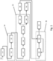
- Fig. 1 shows a flow diagram of a method for producing cement.
- the raw material 10 is first comminuted in a comminution device 12, for example a mill, such as a roller mill, a vertical roller mill or a ball mill.
- the material is then subjected to a thermal treatment 14.
- the thermal treatment comprises heating the material in a preheater 16 and a furnace 18 connected downstream of the preheater, the material in the preheater being heated in countercurrent by the furnace exhaust gas.
- the preheater has a plurality of in Fig. 1 Cyclone stages, not shown, and, for example, a calciner area in which the material is deacidified with the addition of heat.
- the material is thermally treated at maximum temperatures between 1000 ° C and 1450 ° C, so that hydraulically active mineral phases are formed and then cooled in a cooling device 20.
- the cooling device 20 comprises a cooler 22, a crusher 24, a classification device 26, as well as a coarse material cooler 28 and a fine material cooler 30 arranged parallel to it.
- the material in particular the cement clinker, is fed into the cooler 22 promoted.
- the cooler 22 is, for example, a moving grate cooler, a drum cooler, a shaft cooler or a fluidized bed cooler.
- the crusher is, for example, a roller crusher, hammer crusher or a cone crusher, the material having a maximum grain size of about 50 mm after being crushed.
- the material comminuted in the crusher 24 is then fed to a classification device 26, in which the material is classified into two grain sizes, fine material and coarse material.
- the separating cut of the classifying device takes place in particular at 0.1 mm to 5 mm, preferably 0.5 mm to 1 mm, so that the coarse material has a grain size that is larger than 5 mm, preferably larger than 0.5 to 1 mm, in particular larger than 0.1 mm.
- the fine material has a grain size which is less than 5 mm, preferably less than 0.5 to 1 mm, in particular less than 0.1 mm.
- the classification device 26 is, for example, a gas flow classifier in which the material is subjected to a gas flow, so that in particular the airborne fine material is separated from the in particular non-airworthy coarse material.
- the material in a vertical pipeline is charged with a gas stream in countercurrent, the heavier coarse material leaving the pipeline against the gas stream and the fine material with the gas stream.
- the classification device 26 is also conceivable to design the classification device 26 as a dynamic or static classifier. Further configurations of the classification device 26 are with reference to FIG Figures 2 to 5 described.
- the coarse material leaving the classification device 26 is fed to the coarse material cooler 28, which is connected downstream of the classification device 26.
- the coarse material cooler 28 comprises, for example, a fluidized bed cooler or a fixed bed cooler, such as a moving grate cooler through which cooling air flows.
- the fine material leaving the classifying device 26 is fed to the fine material cooler 30 downstream of the classifying device.
- the fine material cooler 30 is arranged parallel to the coarse material cooler 28 and comprises, for example, a fluidized bed cooler or one or more cyclone coolers connected in series. A combination of a fluidized bed cooler and one or more cyclone coolers is also possible.
- the coarse material and the fine material are each further cooled in the coarse material cooler 28 and the fine material cooler 30.
- the cooled coarse material is conveyed to a grinding device 38 by means of a coarse material conveying device 32.
- the grinding device comprises, for example, a ball mill or a vertical roller mill in which the cooled coarse material is comminuted.
- the grinding device 38 is followed by a viewing device 40.
- the classifying device 40 is, for example, a static or a dynamic classifier or a combination of these.
- the cooled fine material is fed to the classifying device 40 by means of a fine material conveying device, it also being conceivable for the coarse and fine material to be brought together and a common task on the mill.
- the viewing device 40 the material, in particular the fine material and the grinder 38 crushed coarse material, in finished product 42 and coarse visible material.
- the sifting device 40 is integrated into the mill 38, the coarse material to be sifted through the sifting device 40 being fed into the mill 38 for further comminution.
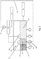
- Fig. 2 shows an embodiment of a classification device 26 in a section of a plant for producing cement, the same reference numerals for the Fig. 1 corresponding components were used.
- the system has a cooling device 20, which comprises, for example, a fluidized bed cooler or a moving grate cooler and on which material for cooling represented by the hatched areas rests. The material is moved in the cooling device 20 in the conveying direction, the conveying direction in Fig. 2 runs from left to right.
- the cooling device 20 has a cooler 22 which removes the material, in particular that from the furnace 18 Fig. 1 leaked cement clinker, cools.
- the material lying in the cooler 22 for cooling comprises both coarse material and fine material and is flowed through by cooling air transversely to the conveying direction from bottom to top.
- the cooling device 20 comprises a plurality of fans 54 of different outputs, which guide cooling air to a plurality of gas inlets, so that the gas flow flows through the material.
- the cooler 22 is followed by the classifying device 26, in which the material in the cooling device 20 is flowed through by a gas stream entering the classifying device 26 through the gas inlet 64, which gas flow has a higher flow rate than the gas flow that the material in the cooler 22 flows through.
- the increased flow velocity of the gas stream ensures that the fine material is captured by the gas stream and is transported with it out of the cooling device.
- the system also has a gas vent 56, 58, wherein in Fig. 2 two gas vents 56, 58 are shown as examples.
- the gas vent 56, 58 is arranged above the classifying device 26, so that the classifying device 26 is arranged between a gas inlet 64 and the gas vent 56, 58.
- the gas exhaust 56, 58 comprises, for example, a fan 52, by means of which the fine material is extracted from the cooling device 60 through the gas exhaust 56, 58.
- a coarse material cooler 28 connects to the classifying device 26 in the conveying direction of the material to be cooled.
- the coarse material 48 is cooled to a temperature of less than 100 ° C. and then leaves the cooling device 20.
- the fine material is transported through the gas outlet 56, 58 to a fine material cooler 30, in which the fine material is cooled to a temperature of less than 100 ° C.
- the fine material cooler 30 comprises at least one cyclone or fluidized bed cooler, in which the fine material 46 is separated from the gas flow.
- the gas flow is conducted via a line 50 to the gas inlet 64 of the classification area 26.
- Classifying the material before it is completely cooled offers the advantage that the separate cooling of the fine material and the coarse material saves the electrical energy required for cooling.
- the cooling of the fine material requires a much shorter dwell time compared to the cooling of the coarse material.
- cooling of the coarse material is made considerably easier by a gas flow if the fine material located between the coarse grains has been separated from the coarse material because a heat transfer of the heat of the coarse material to the gas stream is considerably simplified.
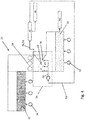
- Fig. 3 shows an embodiment of a classification device 26 in a section of a plant for producing cement, the same reference numerals for the Fig. 1 and 2nd corresponding components were used.
- the system has a crusher 24, which is arranged downstream of the cooler 22 for cooling the unclassified material, so that the material after cooling in the cooler 22 is fed into the crusher 24.
- the crusher 24 is, for example, a roller crusher with three crushing rollers.
- the classifying device 26 is arranged below the crusher 24, so that the material comminuted by the crusher 24 reaches the classifying device 26 due to gravity.
- the classifying device 26 furthermore has a gas inlet 64 and a gas outlet 56, 58 arranged above it, the gas outlet 56, 58 being arranged below the crusher 24.
- a plurality of guide elements 66 are arranged between the gas inlet 64 and the gas outlet 56, 58 Fig. 3 have, for example, a triangular cross section.
- the guide elements 66 are arranged such that the flow velocity of the gas flow exiting the gas inlet 64 through the guide elements 66 is increased.
- the guide elements 66 are in the Essentially arranged at a level relative to each other, gas passages being formed between two guide elements 66.
- the guide elements 66 are arranged relative to one another in such a way that the gas passages widen in the direction of flow of the gas flow, from the gas inlet 64 to the gas outlet 56, 58, so that the gas flow is locally accelerated.
- the coarse material cooler is arranged below the classifying device 26, so that the coarse material classified in the classifying device 26 falls onto the coarse material cooler 28 due to gravity and is cooled by the latter.
- the fine material is transported by means of the gas flow of the classification device 26 to the gas outlet 56, 58 and the fine material cooler 30 and cooled by the latter.
- the fine material cooler 30 comprises a cyclone cooler, so that the gas flow is separated from the fine material and the gas flow is fed via line 50 to the gas inlet 64 of the classification device 64.
- one is in the line 50 in the Figures 2 to 5
- Dedusting device not shown, arranged for dedusting the gas flow.
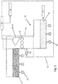
- Fig. 4 shows an embodiment of a classification device 26 in a section of a plant for producing cement, the plant essentially being the plant of FIG Fig. 3 corresponds.
- the classification device 26 of the Fig. 4 differs from Fig. 3 a plurality of guide elements 68, which are arranged offset from one another at at least two different height levels. Examples are in Fig. 4 three guide elements 68 are shown, each of which has an essentially triangular cross section.
- a plurality of perforated plates 70 are arranged between the gas inlet 64 and the gas outlet 56, 58. Six perforated plates 70 are shown as examples, each extending between at least two adjacent guide elements 68 and forming an angle to the horizontal of approximately 45 °.
- the material falling from the crusher into the classification device 26 is discharged through the perforated plates at an angle to the horizontal and to the direction of fall, so that the material is guided through a gap formed between the perforated plates 68 and a guide element 68 adjacent thereto.
- the perforated plates 70 flow onto the material from below when sliding over the perforated plate, as a result of which the fine material is separated from the coarse material.
- the plurality of perforated plates 70 and guide elements 68 also effect a deagglomeration of the material in the classification device 26, which further simplifies the classification.
- the gas flow through the perforated plates 70 and the gaps formed between the perforated plates and the guide elements 68 is locally accelerated, so that the classification can be carried out with less energy expenditure.
- Fig. 5 shows an embodiment of a classification device 26 in a section of a plant for producing cement, the plant essentially being the plant of FIG Fig. 3 and 4th corresponds with the difference that no guide elements and perforated plates are provided. Furthermore, the gas vent 56, 58 is arranged above the crusher 24, so that the gas flow from the gas inlet 64 flows through the crushing gap formed between the crushing rollers and reaches the gas vent 56, 58. The gas flow is accelerated locally, in particular within the sieve and crushing gap, the separation of the fine material from the coarse material taking place at least partially in the crushing gap.
Landscapes
- Engineering & Computer Science (AREA)
- Chemical & Material Sciences (AREA)
- Ceramic Engineering (AREA)
- Organic Chemistry (AREA)
- General Engineering & Computer Science (AREA)
- Materials Engineering (AREA)
- Structural Engineering (AREA)
- Mechanical Engineering (AREA)
- Thermal Sciences (AREA)
- Physics & Mathematics (AREA)
- Environmental & Geological Engineering (AREA)
- Combined Means For Separation Of Solids (AREA)
- Curing Cements, Concrete, And Artificial Stone (AREA)
Applications Claiming Priority (2)
| Application Number | Priority Date | Filing Date | Title |
|---|---|---|---|
| DE102016207720.1A DE102016207720A1 (de) | 2016-05-04 | 2016-05-04 | Verfahren und Anlage zur Herstellung von Zement |
| PCT/EP2017/055024 WO2017190866A1 (de) | 2016-05-04 | 2017-03-03 | Anlage und verfahren zur herstellung eines bindemittels |
Publications (2)
| Publication Number | Publication Date |
|---|---|
| EP3452425A1 EP3452425A1 (de) | 2019-03-13 |
| EP3452425B1 true EP3452425B1 (de) | 2020-04-29 |
Family
ID=58261648
Family Applications (2)
| Application Number | Title | Priority Date | Filing Date |
|---|---|---|---|
| EP17709934.8A Not-in-force EP3452425B1 (de) | 2016-05-04 | 2017-03-03 | Anlage und verfahren zur herstellung eines bindemittels |
| EP17709405.9A Not-in-force EP3452424B1 (de) | 2016-05-04 | 2017-03-03 | Verfahren und anlage zur herstellung von zement |
Family Applications After (1)
| Application Number | Title | Priority Date | Filing Date |
|---|---|---|---|
| EP17709405.9A Not-in-force EP3452424B1 (de) | 2016-05-04 | 2017-03-03 | Verfahren und anlage zur herstellung von zement |
Country Status (4)
| Country | Link |
|---|---|
| EP (2) | EP3452425B1 (da) |
| DE (1) | DE102016207720A1 (da) |
| DK (2) | DK3452425T3 (da) |
| WO (2) | WO2017190865A1 (da) |
Families Citing this family (6)
| Publication number | Priority date | Publication date | Assignee | Title |
|---|---|---|---|---|
| BE1027677B1 (de) * | 2019-10-14 | 2021-05-10 | Thyssenkrupp Ind Solutions Ag | Verfahren und Kühler zum Kühlen von Schüttgut, insbesondere Zementklinker |
| WO2021074059A1 (de) * | 2019-10-14 | 2021-04-22 | Thyssenkrupp Industrial Solutions Ag | Kühler zum kühlen von schüttgut |
| BE1027678B1 (de) * | 2019-10-14 | 2021-05-12 | Thyssenkrupp Ind Solutions Ag | Kühler zum Kühlen von Schüttgut |
| BE1027665B1 (de) * | 2019-10-14 | 2021-05-10 | Thyssenkrupp Ind Solutions Ag | Verfahren und Kühler zum Kühlen von Schüttgut, insbesondere Zementklinker |
| BE1027669B1 (de) * | 2019-10-14 | 2021-05-12 | Thyssenkrupp Ind Solutions Ag | Verfahren und Kühler zum Kühlen von Schüttgut, insbesondere Zementklinker |
| WO2021074055A1 (de) | 2019-10-14 | 2021-04-22 | Thyssenkrupp Industrial Solutions Ag | Kühler und verfahren zum kühlen von schüttgut |
Family Cites Families (10)
| Publication number | Priority date | Publication date | Assignee | Title |
|---|---|---|---|---|
| CH355073A (de) | 1955-09-23 | 1961-06-15 | Dyckerhoff Zementwerke Ag | Verfahren zur Herstellung von Weisszement |
| DE1099436B (de) * | 1959-07-18 | 1961-02-09 | Heidelberg Portland Zement | Verfahren zur Herstellung von Zement, insbesondere Weisszement |
| DE1209040B (de) * | 1964-06-19 | 1966-01-13 | Kloeckner Humboldt Deutz Ag | Verfahren zur Gewinnung eines im wesentlichen alkalifreien Ofenaustrages beim Brennen von schwerfluechtige Alkalien enthaltenden Mineralien |
| DE3521587C1 (de) * | 1985-06-15 | 1989-02-02 | O & K Orenstein & Koppel Ag, 1000 Berlin | Verfahren und Anlage zur Herstellung von weißem Zement |
| JPH068195B2 (ja) * | 1985-10-11 | 1994-02-02 | 日本セメント株式会社 | 白色セメントの製造方法 |
| DE4320025A1 (de) * | 1993-06-17 | 1994-12-22 | Krupp Polysius Ag | Mahlanlage und Verfahren zum Mahlen und Sichten von sprödem Mahlgut |
| DE4414292A1 (de) * | 1994-04-23 | 1995-10-26 | Krupp Foerdertechnik Gmbh | Verfahren und Anlage zur Kühlung von Weißzementklinker |
| DE10018142B4 (de) | 2000-04-12 | 2011-01-20 | Polysius Ag | Kühler und Verfahren zum Kühlen von heißem Schüttgut |
| DE102006026234A1 (de) * | 2006-06-06 | 2007-12-13 | Polysius Ag | Vorrichtung und Verfahren zum Kühlen von Schüttgut |
| TR201809521T4 (tr) * | 2014-07-28 | 2018-07-23 | Heidelbergcement Ag | Çimento klinkeri öğütme yöntemi. |
-
2016
- 2016-05-04 DE DE102016207720.1A patent/DE102016207720A1/de not_active Ceased
-
2017
- 2017-03-03 WO PCT/EP2017/055018 patent/WO2017190865A1/de not_active Ceased
- 2017-03-03 DK DK17709934.8T patent/DK3452425T3/da active
- 2017-03-03 EP EP17709934.8A patent/EP3452425B1/de not_active Not-in-force
- 2017-03-03 EP EP17709405.9A patent/EP3452424B1/de not_active Not-in-force
- 2017-03-03 WO PCT/EP2017/055024 patent/WO2017190866A1/de not_active Ceased
- 2017-03-03 DK DK17709405.9T patent/DK3452424T3/da active
Non-Patent Citations (1)
| Title |
|---|
| None * |
Also Published As
| Publication number | Publication date |
|---|---|
| WO2017190866A1 (de) | 2017-11-09 |
| DE102016207720A1 (de) | 2017-11-09 |
| EP3452424B1 (de) | 2020-04-29 |
| DK3452425T3 (da) | 2020-08-03 |
| WO2017190865A1 (de) | 2017-11-09 |
| DK3452424T3 (da) | 2020-08-03 |
| EP3452425A1 (de) | 2019-03-13 |
| EP3452424A1 (de) | 2019-03-13 |
Similar Documents
| Publication | Publication Date | Title |
|---|---|---|
| EP3452425B1 (de) | Anlage und verfahren zur herstellung eines bindemittels | |
| DE102011055762B4 (de) | Vorrichtung zum Sichten von körnigem Gut und Mahlanlage | |
| DE102014005748B3 (de) | Verfahren und Vorrichtung zum Kühlen und Zerkleinern von heißem Zementklinker | |
| DE102005040519B4 (de) | Verfahren und Vorrichtung zur Vermahlung von heißem und feuchtem Rohmaterial | |
| EP1254873A2 (de) | Verfahren und Anlage zur Herstellung von Zementklinker | |
| DE102006026234A1 (de) | Vorrichtung und Verfahren zum Kühlen von Schüttgut | |
| EP0707187B1 (de) | Anlage zur thermischen Behandlung von mehlförmigen Rohmaterialien | |
| DE2307165A1 (de) | Verfahren und vorrichtung zur direkten kuehlung von feinkoernigem bis grobkoernigem gut mittels kuehlluft | |
| EP0678487A2 (de) | Verfahren und Anlage zur Kühlung von Weisszementklinker | |
| EP3096101B1 (de) | Kühlvorrichtung zum kühlen von schüttgut | |
| DE19502108A1 (de) | Verfahren und Vorrichtung zur Kühlbehandlung von heißem, inhomogenem Schüttgut | |
| DE19726523A1 (de) | Kreislaufmahleinrichtung mit Hochdruck-Walzenpresse und Sichter | |
| WO2008119733A2 (de) | Verfahren zur trocknung feuchter biomasse | |
| EP1287304B1 (de) | Verfahren und anlage zur trocknung von schlamm | |
| DE2338225A1 (de) | Anlage zum kuehlen eines koernigen materials, insbesondere von zementklinker | |
| DE202012003687U1 (de) | Indurationsmaschine mit Vorkühlzone | |
| EP1090686A1 (de) | Mahlanlage | |
| DE102020204519A1 (de) | Verfahren und Vorrichtung zur Herstellung von Zementklinker | |
| EP0013871A1 (de) | Verfahren und Vorrichtung zum Abkühlen von gebranntem Material, wie Sinter oder Pellets | |
| EP1065184A1 (de) | Anlage zur Herstellung von Zementklinker | |
| DE3815763A1 (de) | Verfahren und anlage zur trocknung feuchter materialien wie z. b. zementrohstoffe mittels eines gasstromes | |
| BE1030236B1 (de) | Vorrichtung zur thermischen Behandlung von mineralischem Material mit der Neigung zur Staubbildung | |
| EP3244989B1 (de) | Verfahren zur reduzierung von stickoxiden im abgas einer flugstrombehandlungsanlage | |
| DE202013005996U1 (de) | Klinkerkühler mit Gitterrost zur Separation von großen Klinkerbrocken | |
| BE1028193B1 (de) | Verfahren und Vorrichtung zur Herstellung von Zementklinker |
Legal Events
| Date | Code | Title | Description |
|---|---|---|---|
| STAA | Information on the status of an ep patent application or granted ep patent |
Free format text: STATUS: UNKNOWN |
|
| STAA | Information on the status of an ep patent application or granted ep patent |
Free format text: STATUS: THE INTERNATIONAL PUBLICATION HAS BEEN MADE |
|
| PUAI | Public reference made under article 153(3) epc to a published international application that has entered the european phase |
Free format text: ORIGINAL CODE: 0009012 |
|
| STAA | Information on the status of an ep patent application or granted ep patent |
Free format text: STATUS: REQUEST FOR EXAMINATION WAS MADE |
|
| 17P | Request for examination filed |
Effective date: 20181204 |
|
| AK | Designated contracting states |
Kind code of ref document: A1 Designated state(s): AL AT BE BG CH CY CZ DE DK EE ES FI FR GB GR HR HU IE IS IT LI LT LU LV MC MK MT NL NO PL PT RO RS SE SI SK SM TR |
|
| AX | Request for extension of the european patent |
Extension state: BA ME |
|
| DAV | Request for validation of the european patent (deleted) | ||
| DAX | Request for extension of the european patent (deleted) | ||
| GRAP | Despatch of communication of intention to grant a patent |
Free format text: ORIGINAL CODE: EPIDOSNIGR1 |
|
| STAA | Information on the status of an ep patent application or granted ep patent |
Free format text: STATUS: GRANT OF PATENT IS INTENDED |
|
| RAP1 | Party data changed (applicant data changed or rights of an application transferred) |
Owner name: THYSSENKRUPP INDUSTRIAL SOLUTIONS AG Owner name: THYSSENKRUPP AG |
|
| INTG | Intention to grant announced |
Effective date: 20200103 |
|
| GRAS | Grant fee paid |
Free format text: ORIGINAL CODE: EPIDOSNIGR3 |
|
| GRAA | (expected) grant |
Free format text: ORIGINAL CODE: 0009210 |
|
| STAA | Information on the status of an ep patent application or granted ep patent |
Free format text: STATUS: THE PATENT HAS BEEN GRANTED |
|
| AK | Designated contracting states |
Kind code of ref document: B1 Designated state(s): AL AT BE BG CH CY CZ DE DK EE ES FI FR GB GR HR HU IE IS IT LI LT LU LV MC MK MT NL NO PL PT RO RS SE SI SK SM TR |
|
| REG | Reference to a national code |
Ref country code: GB Ref legal event code: FG4D Free format text: NOT ENGLISH |
|
| REG | Reference to a national code |
Ref country code: CH Ref legal event code: EP |
|
| REG | Reference to a national code |
Ref country code: DE Ref legal event code: R096 Ref document number: 502017004999 Country of ref document: DE |
|
| REG | Reference to a national code |
Ref country code: AT Ref legal event code: REF Ref document number: 1263055 Country of ref document: AT Kind code of ref document: T Effective date: 20200515 |
|
| REG | Reference to a national code |
Ref country code: IE Ref legal event code: FG4D Free format text: LANGUAGE OF EP DOCUMENT: GERMAN |
|
| REG | Reference to a national code |
Ref country code: DK Ref legal event code: T3 Effective date: 20200731 |
|
| REG | Reference to a national code |
Ref country code: NL Ref legal event code: MP Effective date: 20200429 |
|
| REG | Reference to a national code |
Ref country code: LT Ref legal event code: MG4D |
|
| PG25 | Lapsed in a contracting state [announced via postgrant information from national office to epo] |
Ref country code: GR Free format text: LAPSE BECAUSE OF FAILURE TO SUBMIT A TRANSLATION OF THE DESCRIPTION OR TO PAY THE FEE WITHIN THE PRESCRIBED TIME-LIMIT Effective date: 20200730 Ref country code: PT Free format text: LAPSE BECAUSE OF FAILURE TO SUBMIT A TRANSLATION OF THE DESCRIPTION OR TO PAY THE FEE WITHIN THE PRESCRIBED TIME-LIMIT Effective date: 20200831 Ref country code: IS Free format text: LAPSE BECAUSE OF FAILURE TO SUBMIT A TRANSLATION OF THE DESCRIPTION OR TO PAY THE FEE WITHIN THE PRESCRIBED TIME-LIMIT Effective date: 20200829 Ref country code: NO Free format text: LAPSE BECAUSE OF FAILURE TO SUBMIT A TRANSLATION OF THE DESCRIPTION OR TO PAY THE FEE WITHIN THE PRESCRIBED TIME-LIMIT Effective date: 20200729 Ref country code: SE Free format text: LAPSE BECAUSE OF FAILURE TO SUBMIT A TRANSLATION OF THE DESCRIPTION OR TO PAY THE FEE WITHIN THE PRESCRIBED TIME-LIMIT Effective date: 20200429 Ref country code: FI Free format text: LAPSE BECAUSE OF FAILURE TO SUBMIT A TRANSLATION OF THE DESCRIPTION OR TO PAY THE FEE WITHIN THE PRESCRIBED TIME-LIMIT Effective date: 20200429 Ref country code: LT Free format text: LAPSE BECAUSE OF FAILURE TO SUBMIT A TRANSLATION OF THE DESCRIPTION OR TO PAY THE FEE WITHIN THE PRESCRIBED TIME-LIMIT Effective date: 20200429 |
|
| PG25 | Lapsed in a contracting state [announced via postgrant information from national office to epo] |
Ref country code: RS Free format text: LAPSE BECAUSE OF FAILURE TO SUBMIT A TRANSLATION OF THE DESCRIPTION OR TO PAY THE FEE WITHIN THE PRESCRIBED TIME-LIMIT Effective date: 20200429 Ref country code: LV Free format text: LAPSE BECAUSE OF FAILURE TO SUBMIT A TRANSLATION OF THE DESCRIPTION OR TO PAY THE FEE WITHIN THE PRESCRIBED TIME-LIMIT Effective date: 20200429 Ref country code: BG Free format text: LAPSE BECAUSE OF FAILURE TO SUBMIT A TRANSLATION OF THE DESCRIPTION OR TO PAY THE FEE WITHIN THE PRESCRIBED TIME-LIMIT Effective date: 20200729 Ref country code: HR Free format text: LAPSE BECAUSE OF FAILURE TO SUBMIT A TRANSLATION OF THE DESCRIPTION OR TO PAY THE FEE WITHIN THE PRESCRIBED TIME-LIMIT Effective date: 20200429 |
|
| PG25 | Lapsed in a contracting state [announced via postgrant information from national office to epo] |
Ref country code: NL Free format text: LAPSE BECAUSE OF FAILURE TO SUBMIT A TRANSLATION OF THE DESCRIPTION OR TO PAY THE FEE WITHIN THE PRESCRIBED TIME-LIMIT Effective date: 20200429 Ref country code: AL Free format text: LAPSE BECAUSE OF FAILURE TO SUBMIT A TRANSLATION OF THE DESCRIPTION OR TO PAY THE FEE WITHIN THE PRESCRIBED TIME-LIMIT Effective date: 20200429 |
|
| PG25 | Lapsed in a contracting state [announced via postgrant information from national office to epo] |
Ref country code: IT Free format text: LAPSE BECAUSE OF FAILURE TO SUBMIT A TRANSLATION OF THE DESCRIPTION OR TO PAY THE FEE WITHIN THE PRESCRIBED TIME-LIMIT Effective date: 20200429 Ref country code: SM Free format text: LAPSE BECAUSE OF FAILURE TO SUBMIT A TRANSLATION OF THE DESCRIPTION OR TO PAY THE FEE WITHIN THE PRESCRIBED TIME-LIMIT Effective date: 20200429 Ref country code: EE Free format text: LAPSE BECAUSE OF FAILURE TO SUBMIT A TRANSLATION OF THE DESCRIPTION OR TO PAY THE FEE WITHIN THE PRESCRIBED TIME-LIMIT Effective date: 20200429 Ref country code: ES Free format text: LAPSE BECAUSE OF FAILURE TO SUBMIT A TRANSLATION OF THE DESCRIPTION OR TO PAY THE FEE WITHIN THE PRESCRIBED TIME-LIMIT Effective date: 20200429 Ref country code: RO Free format text: LAPSE BECAUSE OF FAILURE TO SUBMIT A TRANSLATION OF THE DESCRIPTION OR TO PAY THE FEE WITHIN THE PRESCRIBED TIME-LIMIT Effective date: 20200429 Ref country code: CZ Free format text: LAPSE BECAUSE OF FAILURE TO SUBMIT A TRANSLATION OF THE DESCRIPTION OR TO PAY THE FEE WITHIN THE PRESCRIBED TIME-LIMIT Effective date: 20200429 |
|
| REG | Reference to a national code |
Ref country code: DE Ref legal event code: R097 Ref document number: 502017004999 Country of ref document: DE |
|
| PG25 | Lapsed in a contracting state [announced via postgrant information from national office to epo] |
Ref country code: SK Free format text: LAPSE BECAUSE OF FAILURE TO SUBMIT A TRANSLATION OF THE DESCRIPTION OR TO PAY THE FEE WITHIN THE PRESCRIBED TIME-LIMIT Effective date: 20200429 Ref country code: PL Free format text: LAPSE BECAUSE OF FAILURE TO SUBMIT A TRANSLATION OF THE DESCRIPTION OR TO PAY THE FEE WITHIN THE PRESCRIBED TIME-LIMIT Effective date: 20200429 |
|
| PLBE | No opposition filed within time limit |
Free format text: ORIGINAL CODE: 0009261 |
|
| STAA | Information on the status of an ep patent application or granted ep patent |
Free format text: STATUS: NO OPPOSITION FILED WITHIN TIME LIMIT |
|
| 26N | No opposition filed |
Effective date: 20210201 |
|
| PG25 | Lapsed in a contracting state [announced via postgrant information from national office to epo] |
Ref country code: SI Free format text: LAPSE BECAUSE OF FAILURE TO SUBMIT A TRANSLATION OF THE DESCRIPTION OR TO PAY THE FEE WITHIN THE PRESCRIBED TIME-LIMIT Effective date: 20200429 |
|
| PG25 | Lapsed in a contracting state [announced via postgrant information from national office to epo] |
Ref country code: MC Free format text: LAPSE BECAUSE OF FAILURE TO SUBMIT A TRANSLATION OF THE DESCRIPTION OR TO PAY THE FEE WITHIN THE PRESCRIBED TIME-LIMIT Effective date: 20200429 |
|
| REG | Reference to a national code |
Ref country code: CH Ref legal event code: PL |
|
| GBPC | Gb: european patent ceased through non-payment of renewal fee |
Effective date: 20210303 |
|
| REG | Reference to a national code |
Ref country code: BE Ref legal event code: MM Effective date: 20210331 |
|
| PG25 | Lapsed in a contracting state [announced via postgrant information from national office to epo] |
Ref country code: IE Free format text: LAPSE BECAUSE OF NON-PAYMENT OF DUE FEES Effective date: 20210303 Ref country code: GB Free format text: LAPSE BECAUSE OF NON-PAYMENT OF DUE FEES Effective date: 20210303 Ref country code: FR Free format text: LAPSE BECAUSE OF NON-PAYMENT OF DUE FEES Effective date: 20210331 Ref country code: CH Free format text: LAPSE BECAUSE OF NON-PAYMENT OF DUE FEES Effective date: 20210331 Ref country code: LI Free format text: LAPSE BECAUSE OF NON-PAYMENT OF DUE FEES Effective date: 20210331 Ref country code: LU Free format text: LAPSE BECAUSE OF NON-PAYMENT OF DUE FEES Effective date: 20210303 |
|
| PG25 | Lapsed in a contracting state [announced via postgrant information from national office to epo] |
Ref country code: BE Free format text: LAPSE BECAUSE OF NON-PAYMENT OF DUE FEES Effective date: 20210331 |
|
| REG | Reference to a national code |
Ref country code: AT Ref legal event code: MM01 Ref document number: 1263055 Country of ref document: AT Kind code of ref document: T Effective date: 20220303 |
|
| PG25 | Lapsed in a contracting state [announced via postgrant information from national office to epo] |
Ref country code: CY Free format text: LAPSE BECAUSE OF FAILURE TO SUBMIT A TRANSLATION OF THE DESCRIPTION OR TO PAY THE FEE WITHIN THE PRESCRIBED TIME-LIMIT Effective date: 20200429 |
|
| PG25 | Lapsed in a contracting state [announced via postgrant information from national office to epo] |
Ref country code: HU Free format text: LAPSE BECAUSE OF FAILURE TO SUBMIT A TRANSLATION OF THE DESCRIPTION OR TO PAY THE FEE WITHIN THE PRESCRIBED TIME-LIMIT; INVALID AB INITIO Effective date: 20170303 Ref country code: AT Free format text: LAPSE BECAUSE OF NON-PAYMENT OF DUE FEES Effective date: 20220303 |
|
| REG | Reference to a national code |
Ref country code: DE Ref legal event code: R081 Ref document number: 502017004999 Country of ref document: DE Owner name: THYSSENKRUPP POLYSIUS GMBH, DE Free format text: FORMER OWNERS: THYSSENKRUPP AG, 45143 ESSEN, DE; THYSSENKRUPP INDUSTRIAL SOLUTIONS AG, 45143 ESSEN, DE Ref country code: DE Ref legal event code: R081 Ref document number: 502017004999 Country of ref document: DE Owner name: THYSSENKRUPP AG, DE Free format text: FORMER OWNERS: THYSSENKRUPP AG, 45143 ESSEN, DE; THYSSENKRUPP INDUSTRIAL SOLUTIONS AG, 45143 ESSEN, DE |
|
| PG25 | Lapsed in a contracting state [announced via postgrant information from national office to epo] |
Ref country code: MK Free format text: LAPSE BECAUSE OF FAILURE TO SUBMIT A TRANSLATION OF THE DESCRIPTION OR TO PAY THE FEE WITHIN THE PRESCRIBED TIME-LIMIT Effective date: 20200429 |
|
| PGFP | Annual fee paid to national office [announced via postgrant information from national office to epo] |
Ref country code: DE Payment date: 20240320 Year of fee payment: 8 |
|
| PGFP | Annual fee paid to national office [announced via postgrant information from national office to epo] |
Ref country code: DK Payment date: 20240326 Year of fee payment: 8 |
|
| PG25 | Lapsed in a contracting state [announced via postgrant information from national office to epo] |
Ref country code: MT Free format text: LAPSE BECAUSE OF FAILURE TO SUBMIT A TRANSLATION OF THE DESCRIPTION OR TO PAY THE FEE WITHIN THE PRESCRIBED TIME-LIMIT Effective date: 20200429 |
|
| REG | Reference to a national code |
Ref country code: DE Ref legal event code: R119 Ref document number: 502017004999 Country of ref document: DE |
|
| REG | Reference to a national code |
Ref country code: DK Ref legal event code: EBP Effective date: 20250331 |
|
| PG25 | Lapsed in a contracting state [announced via postgrant information from national office to epo] |
Ref country code: TR Free format text: LAPSE BECAUSE OF FAILURE TO SUBMIT A TRANSLATION OF THE DESCRIPTION OR TO PAY THE FEE WITHIN THE PRESCRIBED TIME-LIMIT Effective date: 20200429 |
|
| PG25 | Lapsed in a contracting state [announced via postgrant information from national office to epo] |
Ref country code: DE Free format text: LAPSE BECAUSE OF NON-PAYMENT OF DUE FEES Effective date: 20251001 |