EP3449225B1 - Erkennung von flüssigkeitspegeln mithilfe eines spannungsvergleichers - Google Patents
Erkennung von flüssigkeitspegeln mithilfe eines spannungsvergleichers Download PDFInfo
- Publication number
- EP3449225B1 EP3449225B1 EP16900743.2A EP16900743A EP3449225B1 EP 3449225 B1 EP3449225 B1 EP 3449225B1 EP 16900743 A EP16900743 A EP 16900743A EP 3449225 B1 EP3449225 B1 EP 3449225B1
- Authority
- EP
- European Patent Office
- Prior art keywords
- sensing
- die
- location
- fluid
- voltage
- Prior art date
- Legal status (The legal status is an assumption and is not a legal conclusion. Google has not performed a legal analysis and makes no representation as to the accuracy of the status listed.)
- Active
Links
- 239000012530 fluid Substances 0.000 title claims description 212
- 238000010438 heat treatment Methods 0.000 claims description 72
- 238000007639 printing Methods 0.000 claims description 62
- 230000007704 transition Effects 0.000 claims description 21
- 229910021420 polycrystalline silicon Inorganic materials 0.000 claims description 2
- 238000000034 method Methods 0.000 description 58
- 238000012360 testing method Methods 0.000 description 51
- 230000008569 process Effects 0.000 description 50
- 238000005259 measurement Methods 0.000 description 31
- 239000003570 air Substances 0.000 description 20
- 238000001816 cooling Methods 0.000 description 20
- 230000000875 corresponding effect Effects 0.000 description 17
- 239000000758 substrate Substances 0.000 description 11
- 230000004044 response Effects 0.000 description 10
- 238000004891 communication Methods 0.000 description 8
- 238000010586 diagram Methods 0.000 description 8
- 239000007788 liquid Substances 0.000 description 8
- 239000003795 chemical substances by application Substances 0.000 description 7
- XUIMIQQOPSSXEZ-UHFFFAOYSA-N Silicon Chemical compound [Si] XUIMIQQOPSSXEZ-UHFFFAOYSA-N 0.000 description 6
- 230000008859 change Effects 0.000 description 6
- 238000004519 manufacturing process Methods 0.000 description 6
- 238000002161 passivation Methods 0.000 description 6
- 229910052710 silicon Inorganic materials 0.000 description 6
- 239000010703 silicon Substances 0.000 description 6
- 238000010146 3D printing Methods 0.000 description 2
- BOTDANWDWHJENH-UHFFFAOYSA-N Tetraethyl orthosilicate Chemical compound CCO[Si](OCC)(OCC)OCC BOTDANWDWHJENH-UHFFFAOYSA-N 0.000 description 2
- 230000009471 action Effects 0.000 description 2
- 230000005540 biological transmission Effects 0.000 description 2
- 230000003139 buffering effect Effects 0.000 description 2
- 230000000977 initiatory effect Effects 0.000 description 2
- 238000012423 maintenance Methods 0.000 description 2
- 239000000463 material Substances 0.000 description 2
- BASFCYQUMIYNBI-UHFFFAOYSA-N platinum Chemical compound [Pt] BASFCYQUMIYNBI-UHFFFAOYSA-N 0.000 description 2
- 230000001902 propagating effect Effects 0.000 description 2
- XLYOFNOQVPJJNP-UHFFFAOYSA-N water Substances O XLYOFNOQVPJJNP-UHFFFAOYSA-N 0.000 description 2
- 230000006978 adaptation Effects 0.000 description 1
- 239000012080 ambient air Substances 0.000 description 1
- 230000001413 cellular effect Effects 0.000 description 1
- 238000010276 construction Methods 0.000 description 1
- 230000001276 controlling effect Effects 0.000 description 1
- 230000002596 correlated effect Effects 0.000 description 1
- 230000001419 dependent effect Effects 0.000 description 1
- 238000010304 firing Methods 0.000 description 1
- 230000006870 function Effects 0.000 description 1
- 238000007641 inkjet printing Methods 0.000 description 1
- 239000004973 liquid crystal related substance Substances 0.000 description 1
- 238000012986 modification Methods 0.000 description 1
- 230000004048 modification Effects 0.000 description 1
- 230000000737 periodic effect Effects 0.000 description 1
- 229910052697 platinum Inorganic materials 0.000 description 1
- 230000002028 premature Effects 0.000 description 1
- 238000012545 processing Methods 0.000 description 1
- 238000010845 search algorithm Methods 0.000 description 1
- HBMJWWWQQXIZIP-UHFFFAOYSA-N silicon carbide Chemical compound [Si+]#[C-] HBMJWWWQQXIZIP-UHFFFAOYSA-N 0.000 description 1
- 229910010271 silicon carbide Inorganic materials 0.000 description 1
- 230000001360 synchronised effect Effects 0.000 description 1
Images


Classifications
-
- G—PHYSICS
- G01—MEASURING; TESTING
- G01F—MEASURING VOLUME, VOLUME FLOW, MASS FLOW OR LIQUID LEVEL; METERING BY VOLUME
- G01F23/00—Indicating or measuring liquid level or level of fluent solid material, e.g. indicating in terms of volume or indicating by means of an alarm
- G01F23/22—Indicating or measuring liquid level or level of fluent solid material, e.g. indicating in terms of volume or indicating by means of an alarm by measuring physical variables, other than linear dimensions, pressure or weight, dependent on the level to be measured, e.g. by difference of heat transfer of steam or water
- G01F23/24—Indicating or measuring liquid level or level of fluent solid material, e.g. indicating in terms of volume or indicating by means of an alarm by measuring physical variables, other than linear dimensions, pressure or weight, dependent on the level to be measured, e.g. by difference of heat transfer of steam or water by measuring variations of resistance of resistors due to contact with conductor fluid
- G01F23/241—Indicating or measuring liquid level or level of fluent solid material, e.g. indicating in terms of volume or indicating by means of an alarm by measuring physical variables, other than linear dimensions, pressure or weight, dependent on the level to be measured, e.g. by difference of heat transfer of steam or water by measuring variations of resistance of resistors due to contact with conductor fluid for discrete levels
- G01F23/242—Mounting arrangements for electrodes
-
- G—PHYSICS
- G01—MEASURING; TESTING
- G01F—MEASURING VOLUME, VOLUME FLOW, MASS FLOW OR LIQUID LEVEL; METERING BY VOLUME
- G01F23/00—Indicating or measuring liquid level or level of fluent solid material, e.g. indicating in terms of volume or indicating by means of an alarm
- G01F23/22—Indicating or measuring liquid level or level of fluent solid material, e.g. indicating in terms of volume or indicating by means of an alarm by measuring physical variables, other than linear dimensions, pressure or weight, dependent on the level to be measured, e.g. by difference of heat transfer of steam or water
- G01F23/24—Indicating or measuring liquid level or level of fluent solid material, e.g. indicating in terms of volume or indicating by means of an alarm by measuring physical variables, other than linear dimensions, pressure or weight, dependent on the level to be measured, e.g. by difference of heat transfer of steam or water by measuring variations of resistance of resistors due to contact with conductor fluid
- G01F23/246—Indicating or measuring liquid level or level of fluent solid material, e.g. indicating in terms of volume or indicating by means of an alarm by measuring physical variables, other than linear dimensions, pressure or weight, dependent on the level to be measured, e.g. by difference of heat transfer of steam or water by measuring variations of resistance of resistors due to contact with conductor fluid thermal devices
- G01F23/247—Indicating or measuring liquid level or level of fluent solid material, e.g. indicating in terms of volume or indicating by means of an alarm by measuring physical variables, other than linear dimensions, pressure or weight, dependent on the level to be measured, e.g. by difference of heat transfer of steam or water by measuring variations of resistance of resistors due to contact with conductor fluid thermal devices for discrete levels
- G01F23/248—Constructional details; Mounting of probes
-
- B—PERFORMING OPERATIONS; TRANSPORTING
- B41—PRINTING; LINING MACHINES; TYPEWRITERS; STAMPS
- B41J—TYPEWRITERS; SELECTIVE PRINTING MECHANISMS, i.e. MECHANISMS PRINTING OTHERWISE THAN FROM A FORME; CORRECTION OF TYPOGRAPHICAL ERRORS
- B41J2/00—Typewriters or selective printing mechanisms characterised by the printing or marking process for which they are designed
- B41J2/005—Typewriters or selective printing mechanisms characterised by the printing or marking process for which they are designed characterised by bringing liquid or particles selectively into contact with a printing material
- B41J2/01—Ink jet
- B41J2/17—Ink jet characterised by ink handling
- B41J2/175—Ink supply systems ; Circuit parts therefor
- B41J2/17503—Ink cartridges
- B41J2/17526—Electrical contacts to the cartridge
-
- G—PHYSICS
- G01—MEASURING; TESTING
- G01F—MEASURING VOLUME, VOLUME FLOW, MASS FLOW OR LIQUID LEVEL; METERING BY VOLUME
- G01F23/00—Indicating or measuring liquid level or level of fluent solid material, e.g. indicating in terms of volume or indicating by means of an alarm
- G01F23/22—Indicating or measuring liquid level or level of fluent solid material, e.g. indicating in terms of volume or indicating by means of an alarm by measuring physical variables, other than linear dimensions, pressure or weight, dependent on the level to be measured, e.g. by difference of heat transfer of steam or water
- G01F23/24—Indicating or measuring liquid level or level of fluent solid material, e.g. indicating in terms of volume or indicating by means of an alarm by measuring physical variables, other than linear dimensions, pressure or weight, dependent on the level to be measured, e.g. by difference of heat transfer of steam or water by measuring variations of resistance of resistors due to contact with conductor fluid
- G01F23/246—Indicating or measuring liquid level or level of fluent solid material, e.g. indicating in terms of volume or indicating by means of an alarm by measuring physical variables, other than linear dimensions, pressure or weight, dependent on the level to be measured, e.g. by difference of heat transfer of steam or water by measuring variations of resistance of resistors due to contact with conductor fluid thermal devices
- G01F23/247—Indicating or measuring liquid level or level of fluent solid material, e.g. indicating in terms of volume or indicating by means of an alarm by measuring physical variables, other than linear dimensions, pressure or weight, dependent on the level to be measured, e.g. by difference of heat transfer of steam or water by measuring variations of resistance of resistors due to contact with conductor fluid thermal devices for discrete levels
Definitions
- Inkjet printing devices include print heads having a number of nozzles.
- the nozzles are used to eject fluid (e.g., ink) onto a substrate to form an image.
- the nozzles are generally arranged to include at least one column or array such that a properly sequenced ejection of fluid from nozzles may cause characters, symbols, and/or other graphics or images to be printed on the substrate as the print head and the substrate are moved relative to each other.
- Some print heads include integrated fluid level sensors to sense a level of the fluid in the print head. For example, known print heads may use electrodes to determine fluid levels by measuring the resistance of the fluid on the electrodes.
- US 4,129,848 A describes a platinum film resistor device which may be used as a heating element and sensor to determine the level of liquid within a tank.
- WO 2017/184147 A1 which constitutes prior art pursuant to Art. 54(3) EPC, discloses a liquid level sensing device for a printing device comprising a plurality of heaters and temperature sensors arranged on an elongated carrier strip.
- EP 1,384,586 B1 describes an apparatus for detecting a liquid or the amount of a liquid in a container with a plurality of electrodes on a substrate.
- a printing cartridge may include electrical contacts and a fluid container.
- the printing cartridge interfaces with at least one print head through a carriage cradle of a printer to facilitate printing.
- the printing cartridge may include at least one print head housed together in a replaceable device such as an integrated printing cartridge.
- the fluid container may store one color of ink. Also, a number of fluid containers may each store a different color of ink. In other examples, such as when used in 3D printing, the fluid container may store a fusing agent or a detailing agent (e.g., water).
- the printing cartridge may be removed, replaced and/or refilled. Electrical contacts carry electrical signals to and from a controller, for example, to control fluid drop generators in the print heads to eject fluid drops through nozzles and to make fluid level measurements.
- Some known printing cartridges utilize a silicon die as a sensing device to make fluid level measurements. However, in many instances silicon is relatively expensive.
- Some known printing cartridges utilize electrodes embedded in a die to measure fluid level by measuring the resistance of the fluid on the electrodes.
- the controller may control the print heads for ejection of fluid drops from nozzles, for example, by defining a pattern of ejected fluid drops that form characters, symbols and/or other graphics or images on a print medium.
- the pattern of ejected fluid drops may be determined by print job commands and/or command parameters from a data source.
- the level of fluid available in the fluid container may be determined for a number of reasons - for example, to determine an appropriate time for replacement of the cartridge and to avoid premature replacement of the cartridge.
- a sensing die is provided to the cartridge to measure the level of fluid available in the fluid container.
- the sensing die uses a comparator to convert a temperature decay rate at a sensing location in the sensing die into a time-based signal that can be used to sense the presence of fluid near the sensing location.
- the sensing die includes a plurality of heating elements and sensing elements associated with respective fluid levels in the fluid container.
- a heating event is initiated on the sensing die.
- an electrical interface provided to the cartridge may cause a particular heating element to emit a heat pulse.
- a sensing element positioned at or near the sensing location converts the temperature at the sensing location into a sensed voltage. As the temperature at the sensing location decays over time (e.g., after the heating event is stopped), the value of the sensed voltage also decays. The rate at which the temperature and the sensed voltage decays varies based on the type of fluid that borders the sensing element and/or the heating element. For example, a liquid such as ink will thermally conduct heat at a faster rate relative to air.
- a comparator positioned on the sensing die compares the sensed voltage to a voltage threshold and outputs a digital signal indicating which is larger.
- the comparator is an analog-to-digital converter. For example, when the sensed voltage satisfies the voltage threshold (e.g., the value of the sensed voltage is greater than or equal to the voltage threshold), an output of the comparator flips from a first state (e.g., a logical high value indicative of when the sensed voltage satisfies the voltage threshold) to a second state (e.g., a logical low value indicative of when the sensed voltage does not satisfy the voltage threshold).
- a first state e.g., a logical high value indicative of when the sensed voltage satisfies the voltage threshold
- a second state e.g., a logical low value indicative of when the sensed voltage does not satisfy the voltage threshold
- the time it takes for the output of the comparator to flip from the first state to the second state may be used to determine whether the sensing location is bordered by air or a liquid and used to sense the presence of fluid near the sensing location of the cartridge.
- the temperature decay rate varies based on the contents of the fluid container.
- the contents of the fluid container may be all ink (e.g., a filled ink container), ink and air (e.g., a partially-filled ink container), just air (e.g., an empty ink container), or an agent (e.g., a 3D printing agent).
- the temperature decay rate at each sensing location may change with the level of fluid in the fluid container and provides an indication of the level of fluid in the fluid container.
- the on-die controller communicates the level of fluid in the fluid container via digital signals.
- the sensing die includes a plurality of sensing locations.
- the granularity of the fluid level measurement depends on the number of sensing locations in the sensing die. For example, if a sensing die includes five, evenly-spaced sensing locations, the fluid level measurements are provided in twenty percent intervals.
- a sensing location includes a heating element to heat the sensing die at the sensing location and a sensing element to convert the temperature of the sensing die at or substantially near (e.g., within ten micrometers) the sensing location into a voltage.
- Each heating element/sensing element pair is coupled to an element manager to control which heating element/sensing element pair is active at a time.
- the element manager is a multiplexer.
- the output of the comparator is provided to the electrical interface, which records flipping times for a plurality of sensing locations.
- the electrical interface may compare the recorded flipping times to determine when the liquid in the fluid container transitions from a first fluid (e.g., air) to a second fluid (e.g., ink).
- the sensing die is provided a counter.
- the output of the comparator is provided to the counter, which counts a number of clock periods before the comparator output transitions from the first state to the second state.
- the threshold voltage applied by the comparator is a fixed value.
- the comparator may compare the sensed voltage to a four volt threshold.
- a first flipping time (or a first range of times) may be associated with air and a second flipping time (or a second range of times) may be associated with ink.
- the threshold voltage applied by the comparator may be a variable that is sent for different heating events.
- the same flipping time (or range of times) may correspond to air for a first threshold voltage and may correspond to link for a second threshold voltage.
- the present claimed invention includes a sensing die having a plurality of sensing locations and a voltage comparator according to claim 1.
- the sensing die of the present claimed invention when used in a fluid level sensing apparatus reduces the size of the fluid level sensing apparatus integrated with a fluid container, thereby saving cost.
- the fluid level sensing apparatus also facilitate a simple communication protocol that reduces silicon area and cost.
- the present subject matter not part of the claimed invention describes communicating between the printer and the sensing die via digital signals, which are relatively more immune to electronic noise than analog signals.
- timing information e.g., temperature decay rates
- the circuitry on the sensing die facilitates as many sensing locations as fluid levels to be detected.
- the sensing die may include 100 sensing locations to provide fluid level measurements in one percent increments, may include 20 sensing locations to provide fluid level measurements in five percent increments, etc.
- Each sensing location is associated with a heating element that provides (e.g., emits) a heat pulse to the sensing location, a sensing element that converts the temperature into a voltage and an element manager to select when the sensing location is active (e.g., the heating pulse is applied and the sensing element outputs a sensed voltage).
- FIG. 1 is a block diagram of an example printing system 100 that can be used to implement the teachings of this disclosure.
- the example printing system 100 of FIG. 1 includes an example printer 105, example carriage cradles 110 and example printing cartridges 135.
- the printer 105 is an inkjet printer (e.g., a thermal inkjet printer, a piezo inkjet printer, a continuous inkjet printer, etc.).
- the printer 105 is a 3D printer used to print three-dimensional objects.
- the example printer 105 of FIG. 1 includes at least one carriage cradle 110 to receive and exchange at least one corresponding printing cartridge 135.
- the carriage cradles 110 are arranged to establish a fluidic interface between the printing cartridges 135 and a print head 115 via a fluid supply 120.
- the example printer 105 of FIG. 1 includes four carriage cradles 110. However, other implementations may use any other number of carriage cradles 110.
- the print head 115 is a page-wide array print head. However, other types of print heads, such as a scanning print head, may be used, alone or in combination with the aforedescribed print heads.
- a substrate 160 e.g., paper
- the printer 105 may move the carriage cradle 110 over the substrate 160.
- the printer 105 is provided with a controller 125 including a memory 130.
- the controller 125 may retrieve and execute executable code from the memory 130.
- the controller 125 may execute executable code to cause a power supply unit to provide power to the example print head 115.
- the memory 130 may include a variety of information such as an identifier of the printer 105, an identifier of printing cartridges 135 that may be used with the printer 105, calibration data, error information, etc.
- the example printing cartridges 135 of FIG. 1 include a fluid container 140, a memory chip 145 and an electrical interface 150.
- the carriage cradles 110 are arranged to connect the fluid containers 140 to the print head 115 through the fluid supply 120.
- each printing cartridge 135 may include a different fluid in the respective fluid containers 140.
- the fluid in each fluid container 140 may include ink of a specific color (e.g., a cyan color, a magenta color, a yellow color, a black color and/or gray color, etc.).
- the fluid in each fluid container 140 may be an agent such as a fusing agent or a detailing agent (e.g., water).
- a fusing agent e.g., water
- a detailing agent e.g., water
- the memory chip 145 of the printing cartridges 135 may include a variety of information such as an identifier of the type of printing cartridge 135, an identification of the kind of fluid contained in the fluid container 140, calibration data, error information and/or other data.
- the memory chip 145 includes information indicating when the respective printing cartridge 135 should receive maintenance.
- the printer 105 can take appropriate action based on the information contained in the memory chip 145, such as altering printing routines to maintain image quality.
- the controller 125 may retrieve data from the electrical interface(s) 150.
- the controller 125 may request the electrical interface(s) 150 provide cartridge characteristics such as product characteristics, fluid quantity characteristics, fluid type characteristics, etc.
- the printing cartridges 135 may include an integrated print head.
- the print head 115, the fluid supply 120 and the fluid container 140 may be housed together in a replaceable device such as an integrated printing cartridge.
- the print head 115 and the fluid container 140 may be positioned in separate housing (sometimes referred to as an "individual ink container").
- the printing cartridges 135 are provided with a sensing die 155 according to the claimed invention.
- the sensing die 155 includes a plurality of sensing locations to detect presence of fluids within the fluid container 140 and to communicate the fluid levels (e.g., to the controller 125 and/or the electrical interface 155).
- the sensing die 155 facilitates sensing fluid level information upon receipt of a fluid level measurement request.
- a fluid level request is received at the sensing die (e.g., from the controller 125 and/or the electrical interface 150)
- a sensing location on the sensing die 155 is selected and a heat pulse is emitted by the corresponding heating element (e.g., a resistor).
- the sensing die 155 heats-up at the sensing location.
- a cooling period begins and the temperature at the sensing location begins to cool.
- the sensing element e.g., a sensor such as a diode, a resistor, etc.
- the sensing element converts the temperature into a sensed voltage, which is provided to a voltage comparator included in the sensing die 155.
- the voltage comparator compares the sensed voltage to a threshold voltage and outputs a first value (e.g., a logical high value) when the sensed voltage satisfies the threshold voltage, and the voltage comparator outputs a second value (e.g., a logical low value) when the sensed voltage does not satisfy the threshold voltage.
- the electrical interface 150 monitors the output of the voltage comparator and determines a temperature decay rate based on when the cooling period was initiated and when the output of the comparator changed from the first value to the second value. The electrical interface 150 and/or the controller 125 may then transmit a heat pulse to another sensing location until temperature delay rates for at least a portion of the sensing locations are determined.
- the electrical interface 150 and/or the controller 125 identifies the sensing location where presence of a fluid (e.g., ink) transitions from present to not present and, therefore, the level of fluid in the fluid container 140.
- a fluid e.g., ink
- FIG. 2 is a block diagram of an example printing cartridge 135 that can be used with the example printing system 100 of FIG. 1 .
- the printing cartridge 135 includes the example fluid container 140, the example electrical interface 150, example fluidic interfaces 205, 210 and the example sensing die 155 including a plurality of sensing locations 215.
- the example fluidic interfaces 205, 210 establish a fluidic connection with the printer 105 ( FIG. 1 ).
- the first fluidic interface 205 may be a seal ring (e.g., a socket) to receive a fluid pen extending from the carriage cradle 110 ( FIG. 1 ).
- the first fluidic interface 205 may guide a print fluid, such as ink, from the fluid container 140 to the carriage cradle 110.
- the printing system 100 prints by retrieving the first fluid (e.g., a print fluid) from the ink container 140 via the first fluidic interface 205.
- the second fluidic interface 210 may facilitate transporting a gas, such as air, to and from the fluid container 140, for example, to implement pressure control inside the fluid container 140.
- the gas may be ambient air.
- the second fluid interface 210 may be connected to a pressure bag located within the fluid container 140.
- the printing cartridge 135 includes the example sensing die 155.
- the sensing die 155 is made of silicon and is in contact with the fluid container 140 from the top to the bottom of the fluid container 140.
- the example sensing die 155 includes a plurality of sensing locations 215 to sense fluid levels within the fluid container 140 and to communicate the fluid levels, for example, to the controller 125 of FIG. 1 .
- the example sensing locations 215 include a heating element to emit a heat pulse and a sensing element positioned at or near the heating element to convert a temperature to a sensed voltage.
- the sensing locations 215 also include an element manager to control when the respective sensing location 215 is active. For example, the element manager controls which heating element emits a heat pulse and the sensed voltage that is recorded to detect presence of fluid in the fluid container 140.
- a passivation layer between the sensing die 155 and the fluid container 140 may prevent contact between the sensing locations 215 and the fluid being sensed.
- the passivation layer protects the heating elements and the sensing elements associated with each sensing location 215 from damage that may occur from corrosive contact with the fluid (e.g., ink) being sensed.
- the passivation layer may include silicon carbide and/or tetraethyl orthosilicate (TEOS). However, other materials for forming the passivation layer may be used, alone or in combination with the aforedescribed materials.
- the sensing die 155 may omit the passivation layer.
- a voltage comparator provided to the sensing die 155 compares the sensed voltage to a threshold voltage and the flipping time (e.g., the interval measured between when the heat pulse is emitted and when the sensed voltage does not satisfy the threshold voltage) is used to detect the presence of fluid at the sensing location.
- the output of the voltage comparator is transmitted from the sensing die 155 to the electrical interface 150 and/or the controller 125.
- the output of the voltage comparator is converted to a digital code representative of the flipping time and then transmitted from the sensing die 155 to the electrical interface 150 and/or the controller 125.
- the electrical interface 150 may process the fluid level information prior to transmitting the information to the controller 125. For example, the electrical interface 150 may generate a signal based on the flipping times provided by the sensing die 155. The electrical interface 150 may communicate the signal to the controller 125 via an electrical connection established with the printer 105 through the carriage cradle 110.
- the number of sensing locations 215 included in the sensing die 155 varies based on the desired granularity of the fluid level measurements. For example, one hundred sensing locations 215 may be positioned in the sensing die 155 so that each sensing location 215 corresponds to one percent fluid-filled increments. However, other implementations may use any other number of sensing locations 215.
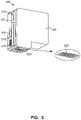
- FIG. 3 is a block diagram of another example printing cartridge 300 that can be used with the example printing system 100 of FIG. 1 .
- the printing cartridge 300 is an integrated printing cartridge including the fluid container 140 and an example print head 305.
- the example printing cartridge 300 also includes an example flexible cable 310, example conductive pads 315, example nozzles 320, the example memory chip 145 and the example sensing die 155 of FIGS. 1 and/or 2 including a plurality of sensing locations 215.
- the example flexible cable 310 is coupled to the sides of the printing cartridge 300 and includes traces that couple the example memory chip 145, the example print head 305, the example conductive pads 315 and the example sensing die 155.
- the example printing cartridge 300 may be installed in the carriage cradle 110 of, for example, the example printer 105 of FIG. 1 .
- the example conductive pads 315 are pressed against corresponding electrical contacts in the carriage cradle 110 to enable the example printer 105 to communicate with and/or control the electrical functions of the printing cartridge 300.
- the example conductive pads 315 enable the printer 105 to access and/or write to the example memory chip 145.
- the memory chip 145 of the illustrated example may include a variety of information such as an identifier of the type of printing cartridge, an identification of the kind of fluid contained in the fluid container, calibration data, error information and/or other data.
- the memory chip 145 includes information indicating when the printing cartridge 300 should receive maintenance.
- the printer 105 can take appropriate action based on the information contained in the memory chip 145, such as altering printing routines to maintain image quality.
- the example printer 105 moves the cradle carriage 110 containing the printing cartridge 300 over the substrate 160.
- the example printer 105 sends electrical signals to the printing cartridge 300 via electrical contacts in the carriage cradle 110.
- the electrical signals pass through the conductive pads 315 of the printing cartridge 300 and are routed through the flexible cable 310 to the print head 305 to energize individual heating elements (e.g., resistors) within the die print head.
- the electrical signal passes through one of the heating elements to create a rapidly expanding vapor bubble of fluid that forces a small droplet of fluid out of a firing chamber within the print head 305 and through the corresponding nozzle 320 onto the surface of the substrate 160 to form an image on the surface of the substrate 160.
- the printing cartridge 300 includes the example sensing die 155.
- the example sensing die 155 includes the plurality of sensing locations 215 to facilitate measuring fluid levels within the fluid container 140.
- the example sensing locations 215 facilitate measuring fluid levels by emitting a heat pulse at a selected sensing location 215 and generating a sensed voltage based on the temperature of the sensing die 155 at the sensing location 215.
- a comparator provided to the sensing die 155 outputs time-based information representative of a temperature decay rate for the sensing location 215.
- the rate at which the temperature decays at the sensing location 215 depends on the type of fluid that borders the sensing location 215. For example, a liquid such as ink will thermally conduct heat at a faster rate relative to air.
- the sensing die 155 then transmits the time-based information to the controller 125 via the flexible cable 310.
- the sensing die 155 may include a counter to generate a digital code based on the time-based information.
- the sensing die 155 may transmit the digital code to the controller 125 via the flexible cable 310.
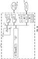
- FIG. 4 is a block diagram of an example implementation of the sensing die 155 according to the claimed invention.
- the sensing die 155 is in contact with the fluid container 140 and in communication with the electrical interface 150 via a bus 405.
- the bus 405 is an Inter-Integrated Circuit (I2C) bus.
- I2C Inter-Integrated Circuit
- other techniques for communicating information between the electrical interface 150 and the sensing die 155 may be used, alone or in combination with the aforedescribed communication interfaces.
- the fluid container 140 includes an example empty space section 410 and an example fluid-filled section 415.
- the sensing die 155 facilitates measuring fluid levels of the fluid container 140 by initiating a heating event at a sensing location 215 and determining a rate at which heat dissipates at the sensing location 215 (e.g., by providing time-based information representative of a temperature decay rate).
- the temperature decay rate at the sensing location 215 depends on the type of fluid in thermal contact with the sensing location 215.
- ink acts as a heat sink.
- the temperature decay rate at a location in thermal contact with air is relatively slower than the temperature decay rate at a location in thermal contact with ink.
- the example sensing die 155 includes five example sensing locations 215a, 215b, 215c, 215d, 215e, an example on-die controller 420 and an example voltage comparator 425.
- the sensing locations collectively referred to as sensing locations 215, enable measuring fluid level in the fluid container 140.
- a first fluid e.g., air
- a second fluid e.g., ink
- the fluid container 140 may be determined to be forty percent filled with ink.
- the granularity of the fluid level measurement depends on the number of sensing locations 215 in the sensing die 155.
- the sensing locations 215 include a heating element 430 to heat the sensing die 155 at the corresponding location and a sensing element 435 to generate a sensed voltage 440 corresponding to the temperature of the sensing die 155 at the corresponding location 215.
- the heating element 430 and the sensing element 435 are positioned so that heat emitted by the heating element 430 may be sensed by the corresponding sensing element 435.
- the heating element 430 emits a heat pulse having a duration of 200-250 microseconds with a power of at least 50 milliwatts.
- the heating element 430 is an electrical resistor.
- other devices for emitting a heat pulse may be used, alone or in combination with the aforedescribed devices.
- the heating element 430 may be implemented by a poly-silicon resistor driven by a MOSFET circuit.
- the example sensing elements 435 of FIG. 4 detect temperature (e.g., emitted by the heating element 430) and generate a sensed voltage 440 corresponding to the detected temperature.
- the sensing elements 435 are implemented using a diode (e.g., a P-N junction diode).
- a diode e.g., a P-N junction diode
- other devices for generating a voltage based on a detected temperature may be used, alone or in combination with the aforedescribed devices.
- each sensing location 215 is individually selectable under the control of a corresponding element manager 445.
- the third element manager 445c enables a heat pulse to pass and the third heating element 430c emits the heat pulse to heat the surrounding area.
- the third element manager 445c also enables the sensed voltage generated by the third sensing element 435c to pass to the example voltage comparator 425.
- the on-die controller 420 controls which sensing location 215 is tested. For example, the on-die controller 420 may select the third sensing location 215c to test and transmit a select signal 450 to activate the third element manager 445c corresponding to the selected sensing location 215c.
- the on-die controller 420 of FIG. 5 also generates a heat pulse to transmit to the selected sensing location 215c via a heat pulse line 455.
- the electrical interface 150 instructs the on-die controller 420 which sensing location 215 to test.
- the electrical interface 150 instructs the on-die controller 420 to sequentially test the sensing locations 215.
- the on-die controller 420 may sequentially actuate (e.g., activate) the element managers 445 in order from top to bottom (e.g., from the first sensing location 215a to the fifth sensing location 215e) or from bottom to top (e.g., from the fifth sensing location 215e to the first sensing location 215a).
- the electrical interface 150 may instruct the on-die controller 420 to test a portion of the sensing locations 215.
- the electrical interface 150 may use a priori search algorithm to identify which sensing locations 215 to test in an effort to reduce the total time and/or the total number of sensing locations 215 that are tested.
- the electrical interface 150 may access a memory (e.g., the example memory chip 145) to obtain information regarding the last sensed fluid level within the fluid container 140 and then actuate (e.g., activate) the sensing locations 215 from nearer to further from the sensing location 215 associated with the last sensed fluid level.
- the electrical interface 150 may use the last sensed fluid level to predict a current fluid level (e.g., based on how many pages were printed since the last measurement) and then actuate the sensing locations 215 near the predicted current fluid level before the sensing locations 215 that are further from the predicted current fluid level.
- a current fluid level e.g., based on how many pages were printed since the last measurement
- other techniques for selecting which sensing locations 215 and/or how many sensing locations 215 to test may be used, alone or in combination with the aforedescribed techniques.
- the voltage comparator 425 is a device that compares the sensed voltage 440 generated by a sensing element 435 to a threshold voltage 460.
- the voltage comparator 425 generates a comparator output 465 representative of whether the sensed voltage satisfies the threshold voltage 460.
- the voltage comparator 425 may generate a first value (e.g., a logical high value) when the sensed voltage is greater than or equal to the threshold voltage 460, and the voltage comparator 425 may generate a second value (e.g., a logical low value) when the sensed voltage is less than the threshold voltage 460.
- the example voltage comparator 425 provides the comparator output 465 to the electrical interface 150.
- the voltage comparator 425 provides the comparator output 465 to the electrical interface 150 via a sensing line.
- the voltage comparator 425 provides the comparator output 465 to the electrical interface 150 via the bus 405.
- the comparator output 465 is time-based information representative of whether the sensed voltage 440 satisfies the threshold voltage 460.
- the electrical interface 150 translates (e.g., maps, interprets, etc.) the time-based information (e.g., the comparator output 465) provided by the voltage comparator 425 to a temperature decay rate.
- the electrical interface 150 may include a timer to determine the duration of the flipping time based on when the instruction to test the sensing location 215 was provided to the on-die controller 420 and when the comparator output 465 flipped from the first state to the second state.
- the electrical interface 150 may start the timer at the end of the heat pulse (e.g., when a cooling period begins).
- the electrical interface 150 monitors the temperature decay rate for at least a portion of the sensing locations 215 and determines a location of transition from a first fluid (e.g., air) to a second fluid (e.g., ink).
- a first fluid e.g., air
- a second fluid e.g., ink
- the temperature decay rate associated with the first, second and third sensing locations 215a, 215b, 215c may be relatively larger compared to the temperature decay rate associated with the fourth and fifth sensing locations 215d, 215e.
- the sensing location 215 associated with the transition location corresponds to the fluid level in the fluid container 140.
- the electrical interface 150 may determine that the fluid level in the fluid container 140 is between forty and sixty percent filled with ink.
- the electrical interface 150 may enhance the resolution of the fluid level measurement based on further processing of the temperature decay rate. For example, while the temperature decay rate at the third sensing location 215c may be within a range of rates associated with bordering air, the temperature decay rate may also indicate that ink is relatively near the third sensing location 215c (e.g., the fluid container 140 is fifty percent filled).
- the electrical interface 150 and/or the on-die controller 420 provides the threshold voltage 460 to the voltage comparator 425.
- the threshold voltage 460 is a fixed value.
- the temperature decay rate for each sensing location 215 that is tested is based on a comparison of the corresponding sensed voltage 440 and the fixed threshold voltage 460.
- the threshold voltage 460 is a variable that is provided for each heating event. For example, when initiating a heating event, the electrical interface 150 may identify the sensing location 215 to test and the threshold voltage 460 value to use. By varying the threshold voltage 460, the time-based information provided by the sensing die 155 (e.g., the comparator output 465) is not directly correlated to a fluid level. For example, a first flipping time may be associated with presence of air for a first threshold voltage and the first flipping time may be associated with presence of ink for a second threshold voltage.
- the information communicated between the electrical interface 150 and the sensing die 155 may be encrypted.
- the electrical interface 150 may encrypt information identifying which sensing location 215 to test and/or which threshold voltage 460 to use when comparing the sensed voltages 440 provided by the sensing elements 435.
- the sensing die 155 and/or the on-die controller 420 may include an encryption handler (e.g., a trusted platform module (TPM)) to decrypt encrypted information received from the electrical interface 150 and/or to encrypt information transmitted to the electrical interface 150.
- TPM trusted platform module
- the electrical interface 150 may obfuscate the time-based information by randomizing the order in which the sensing locations 215 are tested. In some implementations, the electrical interface 150 may repeat testing a sensing location 215. In some such implementations, the electrical interface 150 may use the same threshold voltage when repeating the testing or may use different threshold voltages for the different tests.
- each sensing location 215 included in the sensing die 155 includes a heating element 430 that emits a heat pulse to raise the temperature of the sensing die 155 at a specific location (e.g., the selected sensing location 215).
- the sensing die 155 may include a relatively larger heating element that emits a heat pulse to heat the entire sensing die 155.
- the sensing locations 215 may include the sensing element 435 and the element manager 445 to control when the sensed voltage generated by the sensing element 435 is provided to the voltage comparator 425.
- the electrical interface 150 initiates fluid level measurement by providing a sensing location 215 to test to the on-die controller 420 via the bus 405.
- the electrical interface 150 may initiate fluid level measurement in response to a command from a user (e.g., via a fluid level measurement control on the printer 105, via a fluid level measurement control in a graphical interface, etc.), in response to a page count (e.g., after every one page printed, after every ten pages printed, etc.), etc.
- the electrical interface 150 may encrypt the information regarding the selected sensing location 215c prior to communicating the information to the sensing die 155.
- the selected sensing location 215c may be selected in an ordered sequence, may be selected randomly, may be a repeat test, etc.
- the on-die controller 420 initiates a heating event for the selected sensing location 215c by generating and transmitting a heat pulse via the heat pulse line 455.
- the on-die controller 420 also selects the third element manager 445c associated with the selected sensing location 215c.
- the third element manager 445c allows the heat pulse to pass through to the third heating element 430c, which emits the heat pulse.
- the third sensing element 435c converts the temperature of the sensing die 155 at the third sensing location 215c to a sensed voltage 440, which the third element manager 445c allows to pass to the voltage comparator 425.
- the voltage comparator 425 compares the value of the sensed voltage 440 to the threshold voltage 460.
- the voltage comparator 425 is an analog-to-digital converter that compares the sensed voltage 440 to the threshold voltage 460 and outputs a first value (e.g., a logical high value) when the sensed voltage 440 satisfies the threshold voltage 460, and outputs a second value (e.g., a logical low value) when the sensed voltage 440 does not satisfy the threshold voltage 460.
- the threshold voltage 460 is a fixed value.
- the threshold voltage 460 varies and is provided by the electrical interface 150 for each heating event.
- variable threshold voltage 460 value may be encrypted when transmitted to the sensing die 155.
- the sensing die 155 and/or the on-die controller 420 may include an encryption chip (e.g., a TPM) to decrypt the information related to the sensing location 215 to be tested and/or the threshold voltage 460 to be used by the voltage comparator 425.
- an encryption chip e.g., a TPM
- the output of the comparison performed by the voltage comparator 425 represents time-based information and may be used to determine a temperature decay rate at the selected sensing location 215c.
- the voltage comparator 425 compares the sensed voltage 440 to the threshold voltage 460 and outputs a first value (e.g., a logical high value) when the sensed voltage 440 satisfies the threshold voltage 460 (e.g., is greater than or equal to the threshold voltage 460), and outputs a second value (e.g., a logical low value) when the sensed voltage does not satisfy the threshold voltage 460 (e.g., is less than the threshold voltage 460).
- the comparator output 465 is provided to the electrical interface 150 via the bus 405.
- the comparator output 465 is provided to the electrical interface 150 via a sense line.
- the electrical interface 150 monitors the comparator output 465 and records a flip time representative of a time interval between when the heat pulse was emitted and when the comparator output 465 switched from the first value (e.g., a logical high value) to the second value (e.g., a logical low value).
- the duration of the flip times correspond to a temperature decay rate.
- the electrical interface 150 is able to identify a location of transitions from a first fluid (e.g., air) to a second fluid (e.g., ink).
- the sensing location 215 associated with the transition location corresponds to the fluid level in the fluid container 140.
- the sensing die 155 responds to requests for fluid level measurements from the electrical interface 150. In some examples, the sensing die 155 may respond to requests for fluid level measurements from the controller 125. For example, if a printing cartridge does not include an electrical interface, the sensing die 155 may receive requests to sense fluid levels from the controller 125.
- FIG. 5 is a block diagram of another example implementation of the sensing die 155 of FIGS. 1 , 2 and/or 3, according to an example implementation of the present subject matter.
- the electrical interface 150 communicates with the sensing die 155 and/or the on-die controller 420 via the bus 405.
- the electrical interface 150 instructs the on-die controller 420 which sensing location 215 to test.
- the example on-die controller 420 selects the example element manager 445 associated with the selected sensing location 215 (e.g., the third sensing location 215c).
- the third element manager 445c allows a heat pulse, transmitted via the example heat pulse line 455, to pass to the third heating element 430c, which then emits the heat pulse to heat the sensing die 155 at and/or near the third sensing location 215c.
- the third example sensing element 435c detects the temperature and converts the temperature at the third sensing location 215c to a sensed voltage 440, which the third element manager 445c allows to pass to the example voltage comparator 425.
- the voltage comparator 425 of FIG. 5 compares the sensed voltage 440 provided by the third sensing element 435c to the threshold voltage 460.
- the electrical interface 150 provides a variable threshold voltage 460 to the example voltage comparator 425.
- the example voltage comparator 425 outputs a first value when the sensed voltage 440 satisfies the threshold voltage 460 (e.g., the sensed voltage 440 is greater than or equal to the threshold voltage 460) and outputs a second value when the sensed voltage 440 does not satisfy the threshold voltage 460 (e.g., the sensed voltage 440 is less than the threshold voltage 460).
- the sensing die 155 is provided an example clock 505 and an example counter 510.
- the example clock 505 provides a periodic clock signal to the counter 510.
- the counter 510 converts the time-based information 465 output by the voltage comparator 425 to a digital code 515 based on the clock signal provided clock 505.
- the counter 510 may count the number of rising-edge clock signals received from the clock 505 while the comparator output 465 indicates that the sensed voltage 440 satisfies the threshold voltage 460 (e.g., the comparator output 465 is a logical high value).
- the digital code 515 represents the number of rising-edge clock signals counted by the counter 510 and is provided to the on-die controller 420 to transmit to the electrical interface 150.
- the on-die controller 420 and/or the sensing die 155 includes an encryption chip (e.g., a TPM chip) to encrypt the digital code 515 prior to transmitting to the electrical interface 150.
- the electrical interface 150 translates (e.g., maps, interprets, etc.) the digital code 515 (e.g., the comparator output 465) provided by the counter 510 to a temperature decay rate.
- the clock 505 is implemented by a ring oscillator. However, other techniques for implementing a clock may be used, alone or in combination with the aforedescribed ring oscillator.
- the counter 510 is connected to a clock signal controlled by the electrical interface 150.
- the counter 510 starts counting the number of clock cycles at the end of the heat pulse (e.g., when the cooling period begins). In other implementations, the counter 510 starts counting the number of clock cycles at the start of the heat pulse. In some implementations, the counter 510 stops counting when the comparator output 465 indicates that the sensed voltage 440 fails to satisfy the threshold voltage 460 (e.g., is less than the threshold voltage 460). For example, the counter 510 may start counting the number of clock cycles when the heat pulse ends and stop counting when the comparator output 465 flips from the first state (e.g., a logical high value) to the second state (e.g., a logical low value). In some such implementations, the counter 510 converts the time-based information output from the voltage comparator 425 to the digital code 515.
- the first state e.g., a logical high value
- the second state e.g., a logical low value
- the counter 510 is reset and starts counting at the end of the heat pulse emitted by the heating element 430. In some implementations, the counter 510 is not reset between tests. For example, the counter 510 may count thirty clock cycles before the comparator output 465 flips to the second state during a first test and transit the digital code 515 representative of the thirty clock cycles to the on-die controller 420. When the second test starts, the counter 510 may continue counting from thirty clock cycles and output a digital code 515 representative of the new count. For example, if the counter 510 counted twenty clock cycles during the second test, the counter 510 may output a digital code 515 representative of fifty clock cycles. In some such implementations, the electrical interface 150 may maintain a record of the received digital codes 515 and adjust the clock cycle counts accordingly.
- the counter 510 is enabled and disabled based on the value of the comparator output 465. For example, when the sensed voltage 440 satisfies the threshold voltage 460, the comparator output 465 transitions from the second value (e.g., a logical low value) to the first value (e.g., a logical high value) and the counter 510 begins counting the number of clock cycles before the comparator output 465 transitions from the first value to the second value.
- the second value e.g., a logical low value
- the first value e.g., a logical high value
- FIG. 13 is a block diagram of an example implementation of the element managers 445 of FIGS. 4 and/or 5, according to an example implementation of the present subject matter.
- each sensing location 215 is provided the element manager 445 to control which heating element 430 and sensing element 435 is active at a time.
- the element manager 445 controls which heating element 430 emits the heat pulse provided by the on-die controller 420.
- the element manager 445 also controls which sensed voltage 440 is provided to the voltage comparator 425.
- the example element manager 445 includes an example pulse controller 1305, an example current amplifier 1310 and an example multiplexer 1315.
- the example pulse controller 1305 controls when the heat pulse transmitted by the on-die controller 420 is provided to the heating element 430. For example, when the select signal 450 is a logical high value and a heat pulse is transmitted via the heat pulse line 455, the pulse controller 1305 enables the heat pulse to pass and the heating element 430 to emit the heat pulse. Otherwise, if the select signal 450 is a logical low value and/or there is no heat pulse transmitted on the heat pulse line 455, no heat pulse is provided to the heating element 430 for emitting.
- the pulse controller 1305 may be implemented by a logical AND gate. However, other techniques for controlling the heat pulse may be used, alone or in combination with the aforedescribed pulse controller.
- the example element manager 445 includes the current amplifier 1310 to increase (e.g., "drive") the current output by the pulse controller 1305.
- the current amplifier 1310 may be included with the pulse controller 1305. In other implementations, the current amplifier 1310 may be omitted from the element manager 445.
- the example element manager 445 includes the multiplexer 1315 to control which value to output (e.g., to an adjacent element manager 445 and/or to the voltage comparator 425.
- the multiplexer 1315 is a 2-to-1 multiplexer that forwards the sensed voltage 440 when the select signal 450 is a logical high value and forwards an output from an adjacent element manager 445 when the select signal 450 is a logical low value.
- the multiplexer 1315 when the select signal 450 is a logical high value, the multiplexer 1315 enables the sensed voltage 440 generated by the sensing element 435c to pass to the element manager 445 of the second sensed location 215b.
- the multiplexer 1315 forwards the output of the element manager 445 of the fourth sensing location 215c, which may be a sensed voltage 440 generated by an adjacent sensing element (e.g., the fourth sensing element 435d or the fifth sensing element 435e).
- the output of the element manager 445 of the fourth sensing location 215c which may be a sensed voltage 440 generated by an adjacent sensing element (e.g., the fourth sensing element 435d or the fifth sensing element 435e).
- an adjacent sensing element e.g., the fourth sensing element 435d or the fifth sensing element 435e
- FIG. 6 illustrates a sensing sequence 600 with respect to a heat pulse signal, sensed voltage, and comparator outputs when a fluid (e.g., ink) is present and when the fluid is not present.
- the threshold voltage 460 is a fixed value.
- a heat pulse signal is transmitted to a sensing location 215 on the sensing die 155.
- the on-die controller 420 may select the third element manager 445c associated with the third sensing location 215c and transmit the heat pulse via the heat pulse line 455.
- the third element manager 445c allows the heat pulse to pass to the corresponding heating element 430c, which then emits the heat pulse to heat the sensing die 155 at the sensing location 215c.
- the heat pulse has a power of 50 milliwatts and a duration 200 - 250 microseconds.
- the temperature at the third sensing location 215c increases. Accordingly, the sensed voltage 440 generated by the third sensing element 435c corresponding to the third sensing location 215c also increases. Furthermore, when the sensed voltage 440 is greater than the threshold voltage 460, the comparator outputs the first value (e.g., a logical high value).
- the heating event ends and a cooling period at the sensing location 215c begins.
- the temperature at the third sensing location 215c begins to decay at time T1.
- the rate of the temperature decay rate depends on the type of fluid the third sensing element 435c is proximal.
- an example temperature decay rate 605 measured at the third sensing location 215c when the sensing location 215c is proximate to ink is relatively fast when compared to an example temperate decay rate 610 measured at the third sensing location 215c when the sensing location 215c is not proximate to ink (e.g., is proximal to air).
- the sensed voltage 440 at the third sensing location 215c fails to satisfy the threshold voltage 460 when ink is proximal to the third sensing location 215c.
- the duration between when the cooling period begins at time T1 and the comparator output 465 flips from the logical high value to the logical low value at time T2 is referred to as an ink-based flipping time 615.
- the sensed voltage 440 at the third sensing location 215c fails to satisfy the threshold voltage 460 when ink is not proximate to the third sensing location 215c.
- the duration between when the cooling period begins at time T1 and the comparator output 465 flips from the logical high value to the logical low value at time T3 is referred to as an air-based flipping time 620.
- the electrical interface 150 is able to determine the location where the presence of ink is proximate and then not proximate.
- the ink-based flipping time 615 may represent the time-based information provided to the electrical interface 150 regarding the fourth and fifth sensing locations 215d, 215e.
- the air-based flipping time 620 may represent the time-based information provided to the electrical interface 150 regarding the first, second and third sensing locations 215a, 215b, 215c.
- a propagation delay may occur between when the heat pulse is emitted at time T0, when the cooling period begins at time T1, and/or when the comparator output 465 transitions from the logical high value to the logical low value at time T2 and time T3.
- FIG. 7 illustrates a sensing sequence 700 with respect to location/threshold information, sensed voltage, and comparator outputs based on the threshold voltages and whether ink is proximate to the sensing location of interest.
- the sensing sequence 700 includes a series of heating events initiated at least at four sensing locations 215. Each of the four heating events included in the sensing sequence 700 is associated with a variable threshold voltage 460.
- the location/threshold information identifies the sensing location 215 to test and the threshold voltage 460 that the voltage comparator 425 is to use. In the illustrated sequence, the sensing location 215 is randomized and the threshold voltage 460 varies based on the particular heating event.
- the sensed voltage illustrates the temperature decay rate for the selected sensing location 215 compared to the applied threshold voltage 460.
- the comparator output illustrates the output of the voltage comparator 425 based on a comparison of the sensed voltage 440 and the threshold voltage 460 and the flipping time when the comparator output 465 flips from a logical high value to a logical low value.
- the electrical interface 150 provides location/threshold information associated with a first test, which indicates that the third sensing location 215c is to be tested and a four volt threshold voltage is to be applied by the voltage comparator 425.
- a heating event is initiated (e.g., at heat pulse is emitted) at the third sensing location 215c and the temperature (and the sensed voltage) at the third sensing location 215c increases due to the heat pulse.
- the heat pulse ends and the sensed voltage 440 detected by the example third sensing element 435c begins to decay as the cooling period begins.
- the voltage comparator 425 compares the sensed voltage 440 to the threshold voltage 460 (e.g., four volts) and outputs a logical high value when the sensed voltage 440 is greater than or equal to the threshold voltage and outputs a logical low value when the sensed voltage 440 is less than the threshold voltage.
- the comparator output 465 flips from the first state (e.g., the logical high state) to the second state (e.g., the logical low state).
- the comparator output 465 is provided to the electrical interface 150, which converts the time-based information into a duration (e.g., a value representative of a first flipping time 705).
- the electrical interface 150 provides location/threshold information associated with a second test, which indicates that the fifth sensing location 215e is to be tested and a one volt threshold voltage is to be applied by the voltage comparator 425.
- a heating event is initiated (e.g., at heat pulse is emitted) at the fifth sensing location 215e and the temperature (and the sensed voltage) at the fifth sensing location 215e increases due to the heat pulse.
- the heat pulse ends and the sensed voltage 440 detected by the example fifth sensing element 435e begins to decay as the cooling period begins.
- the voltage comparator 425 compares the sensed voltage 440 to the threshold voltage 460 (e.g., one volt) and outputs a logical high value when the sensed voltage 440 is greater than or equal to the threshold voltage and outputs a logical low value when the sensed voltage 440 is less than the threshold voltage.
- the comparator output 465 flips from the first state (e.g., the logical high state) to the second state (e.g., the logical low state).
- the comparator output 465 is provided to the electrical interface 150, which converts the time-based information into a duration (e.g., a value representative of a second flipping time 710).
- the electrical interface 150 provides location/threshold information associated with a third test, which indicates that the fourth sensing location 215e is to be tested and a three volt threshold voltage is to be applied by the voltage comparator 425.
- a heating event is initiated (e.g., at heat pulse is emitted) at the fourth sensing location 215d and the temperature (and the sensed voltage) at the fourth sensing location 215d increases due to the heat pulse.
- the heat pulse ends and the sensed voltage 440 detected by the example fourth sensing element 435d begins to decay as the cooling period begins.
- the voltage comparator 425 compares the sensed voltage 440 to the threshold voltage 460 (e.g., three volt) and outputs a logical high value when the sensed voltage 440 is greater than or equal to the threshold voltage and outputs a logical low value when the sensed voltage 440 is less than the threshold voltage.
- the comparator output 465 flips from the first state (e.g., the logical high state) to the second state (e.g., the logical low state).
- the comparator output 465 is provided to the electrical interface 150, which converts the time-based information into a duration (e.g., a value representative of a third flipping time 715).
- the electrical interface 150 provides location/threshold information associated with a fourth test, which indicates that the third sensing location 215c is to be tested, again, and a two volt threshold voltage is to be applied by the voltage comparator 425.
- a heating event is initiated (e.g., at heat pulse is emitted) at the third sensing location 215c and the temperature (and the sensed voltage) at the third sensing location 215c increases due to the heat pulse.
- the heat pulse ends and the sensed voltage 440 detected by the example third sensing element 435c begins to decay as the cooling period begins.
- the voltage comparator 425 compares the sensed voltage 440 to the threshold voltage 460 (e.g., two volts) and outputs a logical high value when the sensed voltage 440 is greater than or equal to the threshold voltage and outputs a logical low value when the sensed voltage 440 is less than the threshold voltage.
- the comparator output 465 flips from the first state (e.g., the logical high state) to the second state (e.g., the logical low state).
- the comparator output 465 is provided to the electrical interface 150, which converts the time-based information into a duration (e.g., a value representative of a fourth flipping time 705).
- the first test e.g., initiated at time T0
- the fourth test e.g., initiated at time T9
- the order in which the sensing locations are tested is randomized. Randomizing the order of the sensing locations 215 that are tested and repeating at least one of the sensing locations 215 while measuring fluid levels may be useful for obfuscating the time-based information provided by the sensing die 155 to the electrical interface 150.
- the threshold voltage 460 applied during each test is different.
- the threshold voltage 460 applied by the voltage comparator 425 is four volts and during the fourth test, the threshold voltage applied by the voltage comparator 425 is two volts.
- the duration of the first flipping time 705 and the fourth flipping time 720 is different.
- the temperature decay rate is similar during the first test and the fourth test and, thus, the time it takes for the voltage to stop satisfying the first threshold voltage 460 (e.g., the sensed voltage is greater than or equal to four volts) is relatively less time than the time it takes for the sensed voltage to stop satisfying the fourth threshold voltage 460 (e.g., the sensed voltage is greater than or equal to two volts). Accordingly, the fourth flipping time 720 is longer than the first flipping time 705. Without knowing which sensing location 215 is being tested and what the threshold voltage 460 is applied to the test, the flipping times cannot be reliably mapped to a fluid level measurement, thereby increasing security when transmitting fluid level information.
- the first threshold voltage 460 e.g., the sensed voltage is greater than or equal to four volts
- the fourth threshold voltage 460 e.g., the sensed voltage is greater than or equal to two volts
- FIG. 8 illustrates a sensing sequence 800 with respect to a heat pulse signal, sensed voltage, and clock cycles counted when a fluid (e.g., ink) is present and when the fluid is not present.
- the threshold voltage 460 is a fixed value.
- a heat pulse signal is transmitted to a sensing location 215 on the sensing die 155.
- the on-die controller 420 may select the third element manager 445c associated with the third sensing location 215c and transmit the heat pulse via the heat pulse line 455.
- the third element manager 445c allows the heat pulse to pass to the corresponding heating element 430c, which then emits the heat pulse to heat the sensing die 155 at the sensing location 215c.
- the heat pulse has a power of 50 milliwatts and a duration 200 - 250 microseconds.
- the temperature at the third sensing location 215c increases. Accordingly, the sensed voltage 440 generated by the third sensing element 435c corresponding to the third sensing location 215c also increases. Furthermore, when the sensed voltage 440 is greater than the threshold voltage 460, the comparator outputs the first value (e.g., a logical high value). In the illustrated sequence 800, when the voltage comparator 425 outputs the logical high value, the example counter 510 begins counting a number of clock cycles before the comparator output 465 transitions from the logical high value to the logical low value.
- the first value e.g., a logical high value
- the heating event ends and the cooling period at the third sensing location 215c begins.
- the temperature at the third sensing location 215c begins to decay at time T1.
- the rate of the temperature decay rate depends on the type of fluid the third sensing element 435c is proximal.
- an example temperature decay rate 805 measured at the third sensing location 215c when the sensing location 215c is proximate to ink is relatively fast when compared to an example temperate decay rate 810 measured at the third sensing location 215c when the sensing location 215c is not proximate to ink (e.g., is proximal to air).
- the sensed voltage 440 at the third sensing location 215c fails to satisfy the threshold voltage 460 when ink is proximal to the third sensing location 215c.
- the counter 510 stops counting. In the illustrated sequence, the counter 510 counts four clock cycles during a first flipping time 815.
- the sensed voltage 440 at the third sensing location 215c fails to satisfy the threshold voltage 460 when ink is not proximate to the third sensing location 215c.
- the counter 510 stops counting. In the illustrated sequence, the counter 510 counts twenty clock cycles during a second flipping time 820.
- the number of clock cycles counted by the counter 510 during a flipping time depends on the period during which the comparator output 465 stays in the logical high state and based on characteristics of the clock 505. For example, the number of clock cycles that are counted during the second flipping time 820 may be higher when the clock 505 has a relatively higher frequency than when the clock 505 has a lower frequency.
- a propagation delay may occur between when the heat pulse is emitted at time T0, when the cooling period begins at time T1, and/or when the counter 510 stops counting clock cycles due to the comparator output 465 transitions from the logical high value to the logical low value at time T2 and time T3.
- FIGS. 1-5 and/or 13 While an example manner of implementing the printing system 100 is illustrated in FIGS. 1-5 and/or 13, in some examples, at least one of the elements, processes and/or devices illustrated in FIGS. 1-5 and/or 13 may be combined, divided, re-arranged, omitted, eliminated and/or implemented in any other way. Further, the example controller 125, the example memory 130, the example memory chip 145, the example electrical interface 150, the example on-die controller 420, the example voltage comparator 425, the example element managers 445, the example clock 505, the example counter 510, the example pulse controller 1305, the example current amplifier 1310, the example multiplexer 1315 and/or, more generally, the example printing system 100 of FIGS.
- 1-5 and/or 13 can be implemented by a circuit(s), a programmable processor(s), an application specific integrated circuit(s) (ASIC(s)), a programmable logic device(s) (PLD(s)), a field programmable gate array(s) (FPGA(s)) and/or a field programmable logic device(s) (FPLD(s)), etc.
- ASIC application specific integrated circuit
- PLD programmable logic device
- FPGA field programmable gate array
- FPLD field programmable logic device
- At least one of the example controller 125, the example memory 130, the example memory chip 145, the example electrical interface 150, the example on-die controller 420, the example element managers 445, the example clock 505, the example counter 510, the example pulse controller 1305, the example current amplifier 1310 and/or the example multiplexer 1315 is hereby expressly defined to include a tangible computer readable storage device or storage disc such as a memory, DVD, CD, Blu-ray, etc. storing the software and/or firmware.
- the example printing system 100 of FIGS. 1-5 and/or 13 may include an element(s), process(es) and/or devices in addition to, or instead of, those illustrated and/or may include more than one of any or all of the illustrated elements, processes and devices.
- FIGS. 9 , 10 and/or 11 Flowcharts representative of example machine readable instructions for implementing the printing system 100 of FIGS. 1-5 and/or 13 are shown in FIGS. 9 , 10 and/or 11, said flowcharts not part of the claimed invention.
- the machine readable instructions comprise a program for execution by a processor such as the processor 1212 shown in the example processor platform 1200 discussed below in connection with FIG. 12 .
- the programs may be implemented in software stored on a tangible computer readable storage medium such as a CD-ROM, a floppy disk, a hard drive, a digital versatile disk (DVD), a Blu-ray disk, or a memory associated with the processor 1212, but the entire program and/or parts thereof can alternatively be executed by a device other than the processor 1212 and/or implemented in firmware or dedicated hardware.
- a tangible computer readable storage medium such as a CD-ROM, a floppy disk, a hard drive, a digital versatile disk (DVD), a Blu-ray disk, or a memory associated with the processor 1212
- DVD digital versatile disk
- Blu-ray disk a memory associated with the processor 1212
- the entire program and/or parts thereof can alternatively be executed by a device other than the processor 1212 and/or implemented in firmware or dedicated hardware.
- FIGS. 9 , 10 and/or 11 many other methods of implementing the example printing system 100 may also be used. For example, the order of execution of the blocks may be changed, and
- FIGS. 9 , 10 and/or 11 may be implemented using coded instructions (e.g., computer and/or machine readable instructions) stored on a tangible computer readable storage medium such as a hard disk drive, a flash memory, a read-only memory (ROM), a compact disk (CD), a digital versatile disk (DVD), a cache, a random-access memory (RAM) and/or any other storage device or storage disk in which information is stored for any duration (e.g., for extended time periods, permanently, for brief instances, for temporarily buffering, and/or for caching of the information).
- coded instructions e.g., computer and/or machine readable instructions
- a tangible computer readable storage medium such as a hard disk drive, a flash memory, a read-only memory (ROM), a compact disk (CD), a digital versatile disk (DVD), a cache, a random-access memory (RAM) and/or any other storage device or storage disk in which information is stored for any duration (e.g., for extended time periods, permanently
- tangible computer readable storage medium is expressly defined to include any type of computer readable storage device and/or storage disk and to exclude propagating signals and to exclude transmission media.
- tangible computer readable storage medium and “tangible machine readable storage medium” are used interchangeably. The example processes of FIGS.
- non-transitory computer and/or machine readable medium such as a hard disk drive, a flash memory, a read-only memory, a compact disk, a digital versatile disk, a cache, a random-access memory and/or any other storage device or storage disk in which information is stored for any duration (e.g., for extended time periods, permanently, for brief instances, for temporarily buffering, and/or for caching of the information).
- a non-transitory computer readable medium is expressly defined to include any type of computer readable storage device and/or storage disk and to exclude propagating signals and to exclude transmission media.
- the process 900 of FIG. 9 begins at block 902 by determining whether a fluid level read request was received.
- the electrical interface 150 may receive a fluid level read request in response to a command from a user, in response to a page count, etc.
- the process 900 of FIG. 9 transmits a heat pulse to a selected sensing location 215 on the sensing die 155.
- the electrical interface 150 may provide a sensing location (e.g., the third sensing location 215c) to the on-die controller 420, which then selects the third sensing location 215c by enabling the third element manager 445c.
- the third element manager 445c allows the heat pulse to pass to the third heating element 430c and the third heating element 430 emits the heat pulse to heat the third sensing location 215c.
- the heat pulse has a duration of 200-250 microseconds and a power of 50 milliwatts.
- the heat pulse ends and a cooling period begins.
- the third sensing element 435c associated with the third sensing location detects the temperature of the sensing die 155 proximate to the third sensing location 215c and generates a sensed voltage 440 based on the detected temperature.
- the example voltage comparator 425 compares the sensed voltage 440 to the threshold voltage 460.
- the electrical interface 150 provides a fixed value to the voltage comparator 425. If, at block 914, the voltage comparator 425 determines that that sensed voltage 440 satisfies the threshold voltage 460 (e.g., the sensed voltage 440 is greater than or equal to the threshold voltage 460), then control returns to block 912 to compare the sensed voltage 440 to the threshold voltage 460.
- the process 900 determines whether there is another sensing location 215 to test.
- the electrical interface 150 may test a portion of the sensing locations 215 and/or all of the sensing locations 215 included in the sensing die 155. If, at block 918, the process 900 determines that there is another sensing location 215 to test, then control returns to block 904 to transmit a heat pulse to the selected sensing location 215.
- the process 900 determines a fluid level measurement based on the recorded flipping times.
- the electrical interface 150 may process the recorded flipping times and identify a location where the presence of a fluid (e.g., ink) transitions from proximate to not proximate based on a change in the recorded flipping times.
- the process 900 FIG. 9 determines whether to continue making fluid level measurements. If, at block 922, the process 900 of FIG. 9 determines to continue making fluid level measurements, control returns to block 902 to determine whether a fluid level read request was received. Otherwise, the example process 900 of FIG. 9 ends.
- the process 1000 of FIG. 10 begins at block 1002 by determining whether a fluid level read request was received.
- the electrical interface 150 may receive a fluid level read request in response to a command from a user, in response to a page count, etc.
- the process 1000 of FIG. 10 transmits location information identifying a location to test and threshold information identifying a threshold voltage to apply.
- the electrical interface 150 may instruct the on-die controller 420 to test the third sensing location 215c and that the voltage comparator 425 is to use a four volt threshold voltage 460 when comparing the sensed voltage 400.
- the location information and/or the threshold information is encrypted by the electrical interface 150 prior to transmitting to the on-die controller 420 and/or the sensing die 155.
- the process 1000 of FIG. 10 emits a heat pulse at the selected sensing location and heats the sensing die 155 at the third sensing location 215c.
- the heat pulse has a duration of 200-250 microseconds and a power of 50 milliwatts.
- the heat pulse ends and a cooling period begins.
- the third sensing element 435c associated with the third sensing location 215c detects the temperature of the sensing die 155 proximate to the third sensing location 215c and generates a sensed voltage 440 based on the detected temperature.
- the example voltage comparator 425 compares the sensed voltage 440 to the threshold voltage 460. If, at block 1014, the voltage comparator 425 determines that that sensed voltage 440 satisfies the threshold voltage 460 (e.g., the sensed voltage 440 is greater than or equal to four volts), then control returns to block 1012 to compare the sensed voltage 440 to the threshold voltage 460.
- the process 1000 determines whether there is another sensing location 215 to test.
- the electrical interface 150 may test a portion of the sensing locations 215 and/or all of the sensing locations 215 included in the sensing die 155. If, at block 1018, the process 1000 determines that there is another sensing location 215 to test, then control returns to block 1004 to transmit a heat pulse to the selected sensing location 215. In some implementations, the process 1000 obfuscates the sensing locations 215 being tested by randomizing the order that the sensing locations 215 are tested, repeating testing of at least one sensing location 215, etc.
- the process 1000 determines a fluid level measurement based on the recorded flipping times and the applied threshold voltages.
- the electrical interface 150 may process the recorded flipping times and identify a location where the presence of a fluid (e.g., ink) transitions from proximate to not proximate based on a change in the recorded flipping times.
- the process 1000 FIG. 10 determines whether to continue making fluid level measurements. If, at block 1022, the process 1000 of FIG. 10 determines to continue making fluid level measurements, control returns to block 1002 to determine whether a fluid level read request was received. Otherwise, the example process 1000 of FIG. 10 ends.
- the process 1100 of FIG. 11 begins at block 1102 by determining whether a fluid level read request was received.
- the electrical interface 150 may receive a fluid level read request in response to a command from a user, in response to a page count, etc.
- the process 1100 of FIG. 11 transmits a heat pulse to a selected sensing location 215 on the sensing die 155.
- the electrical interface 150 may provide a sensing location (e.g., the third sensing location 215c) to the on-die controller 420, which then selects the third sensing location 215c by enabling the third element manager 445c.
- the process 1100 of FIG. 11 resets the counter 510. In some implementations, the process 1100 may not reset the counter 510.
- the heat pulse ends and a cooling period begins.
- the example counter 510 begins counting clock cycles at the start of the cooling period.
- the third sensing element 435c associated with the third sensing location 215c detects the temperature of the sensing die 155 proximate to the third sensing location 215c and generates a sensed voltage 440 based on the detected temperature.
- the example voltage comparator 425 compares the sensed voltage 440 to the threshold voltage 460.
- the electrical interface 150 provides a fixed value to the voltage comparator 425. In some implementations, the electrical interface 150 varies the value of the threshold voltage 460 for different tests.
- the voltage comparator 425 determines that that sensed voltage 440 satisfies the threshold voltage 460 (e.g., the sensed voltage 440 is greater than or equal to the threshold voltage 460), then control returns to block 1112 to compare the sensed voltage 440 to the threshold voltage 460.
- the process 1100 of FIG. 11 stops counting clock cycles.
- the example counter 510 may stop counting clock cycles when the comparator output 465 transitions from the logical high value to the logical low value.
- the process 1100 encrypts the example digital code 515 representative of the number of clock cycles counted by the counter 510.
- the counter 510 may output the digital code 515 to the on-die controller 420, which may include an encryption chip (e.g., a TPM chip) to encrypt the digital code 515.
- the process 1100 outputs the encrypted digital code 515 from the sensing die 155 to the electrical interface 150.
- the process 1100 determines whether there is another sensing location 215 to test. For example, the electrical interface 150 may test a portion of the sensing locations 215 and/or all of the sensing locations 215 included in the sensing die 155. If, at block 1122, the process 1100 determines that there is another sensing location 215 to test, then control returns to block 1104 to transmit a heat pulse to the selected sensing location 215.
- the process 1100 determines a fluid level measurement based on the recorded flipping times (e.g., the encrypted digital codes 515).
- the electrical interface 150 may process the recorded flipping times and identify a location where the presence of a fluid (e.g., ink) transitions from proximate to not proximate based on a change in the recorded flipping times.
- the process 1100 FIG. 11 determines whether to continue making fluid level measurements. If, at block 1126, the process 1100 of FIG. 11 determines to continue making fluid level measurements, control returns to block 1102 to determine whether a fluid level read request was received. Otherwise, the example process 1100 of FIG. 11 ends.
- FIG. 12 is a block diagram of an example processor platform 1200 not part of the claimed invention capable of executing machine-readable instructions to implement the processes of FIGS. 9 , 10 and/or 11 and/or the printing system 100 of FIGS. 1-5 and/or 13.
- the processor platform 1200 can be, for example, a server, a personal computer, or any other type of computing device.
- the processor platform 1200 of the illustrated example includes a processor 1212.
- the processor 1212 of the illustrated example is hardware.
- the processor 1212 can be implemented by at least one of integrated circuits, logic circuits, microprocessors or controllers from any desired manufacturer.
- the processor 1212 of the illustrated example includes a local memory 1213 (e.g., a cache).
- the processor 1212 of the illustrated example is in communication with a main memory including a volatile memory 1214 and a non-volatile memory 1216 via a bus 1218.
- the volatile memory 1214 may be implemented by Synchronous Dynamic Random Access Memory (SDRAM), Dynamic Random Access Memory (DRAM), RAMBUS Dynamic Random Access Memory (RDRAM) and/or any other type of random access memory device.
- the non-volatile memory 1216 may be implemented by flash memory and/or any other desired type of memory device. Access to the main memory 1214, 1216 is controlled by a memory controller.
- the main memory may include the volatile memory 814 alone.
- the main memory may include the non-volatile memory 816 alone.
- the processor platform 1200 of the illustrated example also includes an interface circuit 1220.
- the interface circuit 1220 may be implemented by any type of interface standard, such as an Ethernet interface, a universal serial bus (USB), and/or a PCI express interface.
- At least one input device 1222 is connected to the interface circuit 1220.
- the input device(s) 1222 permit(s) a user to enter data and commands into the processor 1212.
- the input device(s) can be implemented by, for example, an audio sensor, a microphone, a camera (still or video), a keyboard, a button, a mouse, a touchscreen, a track-pad, a trackball, isopoint and/or a voice recognition system.
- At least one output device 1224 is also connected to the interface circuit 1220 of the illustrated example.
- the output devices 1224 can be implemented, for example, by display devices (e.g., a light emitting diode (LED), an organic light emitting diode (OLED), a liquid crystal display, a cathode ray tube display (CRT), a touchscreen, a tactile output device, a printer and/or speakers).
- the interface circuit 1220 of the illustrated example thus, may include a graphics driver card, a graphics driver chip or a graphics driver processor.
- the interface circuit 1220 of the illustrated example may also include a communication device such as a transmitter, a receiver, a transceiver, a modem and/or network interface card to facilitate exchange of data with external machines (e.g., computing devices of any kind) via a network 1226 (e.g., an Ethernet connection, a digital subscriber line (DSL), a telephone line, coaxial cable, a cellular telephone system, etc.).
- a communication device such as a transmitter, a receiver, a transceiver, a modem and/or network interface card to facilitate exchange of data with external machines (e.g., computing devices of any kind) via a network 1226 (e.g., an Ethernet connection, a digital subscriber line (DSL), a telephone line, coaxial cable, a cellular telephone system, etc.).
- DSL digital subscriber line
- the processor platform 1200 of the illustrated example may also include at least one mass storage device 1228 for storing software and/or data.
- mass storage devices 1228 include floppy disk drives, hard drive disks, compact disk drives, Blu-ray disk drives, RAID systems, and digital versatile disk (DVD) drives.
- Coded instructions 1232 to implement the processes of FIGS. 9 , 10 and/or 11 may be stored in the mass storage device 1228, in the volatile memory 1214, in the non-volatile memory 1216, and/or on a removable tangible computer readable storage medium such as a CD or DVD.
- fluid level information is sensed at a plurality of sensing locations included in a sensing die.
- the sensing die is integrated with a fluid container and extends from the top of the fluid container to the bottom of the fluid container, or a portion of the fluid container.
- a heating event is initiated at a selected sensing location and a heat pulse is emitted by a heating element.
- a sensing element positioned at or near the sensing location detects the temperature of the sensing die and converts the temperature into a sensed voltage.
- a voltage comparator compares the sensed voltage to a threshold voltage and generates a continuous output indicative of whether the sensed voltage satisfies the threshold voltage.
- the continuous output generated by the voltage comparator is time-based information representing of a duration that the sensed voltage satisfies the threshold voltage.
- the threshold voltage is a fixed value that is applied to each tested sensing location.
- the threshold voltage is a variable that may change from one heating event to the next heating event.
- Information from the sensing die is transmitted to the electrical interface, which then processes the received information to determine a location where presence of a fluid (e.g., ink) transitions from present to not present.
- the information received form the sensing die is time-based information.
- the electrical interface may monitor the comparator output and record when the comparator output flips from a logical high state to a logical low state.
- the sensing die may include a counter to convert the time-based information output by the voltage comparator to a digital code representative of a number of clock cycles that the output of the voltage comparator stayed in the logical high state before flipping to the logical low state.
- the disclosed apparatus and articles of manufacture save print head cost. Furthermore, the disclosed apparatus and articles of manufacture provide a simple communication protocol that reduces silicon area and costs associated with embedding silicon. The disclosed apparatus and articles of manufacture also preserve the sensing elements and the heating elements via a passivation layer that protects the heating elements and the sensing elements associated with each sensing location 215 from damage that may occur from corrosive contact with the fluid (e.g., ink) being sensed.
- the fluid e.g., ink
Claims (15)
- Erfassungschip (155), der Folgendes umfasst:eine Vielzahl von Erfassungsstellen (215a-e) in thermischem Kontakt mit einem Fluidbehälter (140); undeinen Spannungskomparator (425), um zeitbasierte Informationen durch ein Vergleichen einer erfassten Spannung (440), die an einer ausgewählten Erfassungsstelle (215c) der Vielzahl von Erfassungsstellen (215a-e) erzeugt wird, mit einer Schwellenspannung (460) auszugeben, wobei die zeitbasierten Informationen darstellend sind, ob ein Fluid an der ausgewählten Erfassungsstelle (215c) vorhanden ist.
- Erfassungschip (155) nach Anspruch 1, wobei die ausgewählte Erfassungsstelle (215c) ein Erfassungselement (435c) einschließt, um eine Temperatur festzustellen und die erfasste Spannung (440) basierend auf der festgestellten Temperatur zu erzeugen.
- Erfassungschip (155) nach Anspruch 2, wobei das Erfassungselement (435c) eine P-N-Flächendiode ist.
- Erfassungschip (155) nach Anspruch 1, wobei die ausgewählte Erfassungsstelle (215c) ein Heizelement (430c) einschließt, um einen Heizimpuls auszusenden, um den Erfassungschip (155) an der ausgewählten Erfassungsstelle (215c) zu erhitzen.
- Erfassungschip (155) nach Anspruch 4, wobei das Heizelement (430c) ein Polysilizium-Widerstand ist.
- Erfassungschip (155) nach Anspruch 1, wobei der Erfassungschip (155) ein Heizelement und eine Vielzahl von Erfassungselementen (435a-e) einschließt, die durch den Erfassungschip (155) positioniert sind, wobei die Position jedes Erfassungselements (435a-e) einem Fluidstand zugeordnet ist.
- Erfassungschip (155) nach Anspruch 1, der ferner einen Elementverwalter (445a-e) einschließt, um zu steuern, wann die ausgewählte Erfassungsstelle (215c) betätigt wird.
- Erfassungschip (155) nach Anspruch 7, wobei der Elementverwalter (445a-e) zu Folgendem dient:Weiterleiten eines Heizimpulses an ein Heizelement (430a-e) um auszusenden, wenn der Elementverwalter (445a-e) ausgewählt wird; undWeiterleiten der erfassten Spannung (440) von der ausgewählten Erfassungsstelle (215c) an den Spannungskomparator (425).
- Erfassungschip (155) nach Anspruch 8, wobei die erfasste Spannung (440) eine erste erfasste Spannung ist, wobei der Elementverwalter (445a-e) zu Folgendem dient:
Weiterleiten einer zweiten erfassten Spannung von einem angrenzenden Elementverwalter (445a-e), wenn der Elementverwalter (445a-e) nicht ausgewählt ist. - Erfassungschip (155) nach einem der vorstehenden Ansprüche, wobei:
jede der Erfassungsstellen (215a-e) einem Fluidstand in dem Fluidbehälter (140) zugeordnet ist, wobei die Vielzahl von Erfassungsstellen (215a-e) dazu dienen, ein Vorhandensein eines Fluids innerhalb des Fluidbehälters (140) bei dem jeweiligen Fluidstand wahlweise festzustellen. - Erfassungschip (155) nach einem der vorstehenden Ansprüche, wobei eine Dauer, die den zeitbasierten Informationen zugeordnet ist, einer Temperaturabfallrate entspricht.
- Erfassungschip (155) nach Anspruch 10, der ferner eine On-Chip-Steuerung (420) einschließt, um einen Heizimpuls an die ausgewählte Erfassungsstelle (215c) zu übermitteln, um zu bewirken, dass die ausgewählte Erfassungsstelle (215c) das Vorhandensein des Fluids feststellt.
- Erfassungschip (155) nach einem der vorstehenden Ansprüche, der ferner eine elektrische Schnittstelle (150) einschließt, um:eine Ausgabe (465) von dem Spannungskomparator (425) auf eine Temperaturabfallrate abzubilden; undeine Übergangsstelle basierend auf der Temperaturabfallrate zu identifizieren, wobei die Übergangsstelle für einen Fluidstand des Fluidbehälters (140) darstellend ist.
- Erfassungschip (155) nach einem der vorstehenden Ansprüche, wobei die Schwellenspannung (460) ein fester Wert ist.
- Druckpatrone (135, 300), die Folgendes umfasst:einen Fluidbehälter (140); undeinen Erfassungschip (155) nach einem der vorstehenden Ansprüche.
Applications Claiming Priority (1)
| Application Number | Priority Date | Filing Date | Title |
|---|---|---|---|
| PCT/US2016/030254 WO2017189010A1 (en) | 2016-04-29 | 2016-04-29 | Detecting fluid levels using a voltage comparator |
Publications (3)
| Publication Number | Publication Date |
|---|---|
| EP3449225A1 EP3449225A1 (de) | 2019-03-06 |
| EP3449225A4 EP3449225A4 (de) | 2019-12-04 |
| EP3449225B1 true EP3449225B1 (de) | 2022-09-07 |
Family
ID=60159922
Family Applications (1)
| Application Number | Title | Priority Date | Filing Date |
|---|---|---|---|
| EP16900743.2A Active EP3449225B1 (de) | 2016-04-29 | 2016-04-29 | Erkennung von flüssigkeitspegeln mithilfe eines spannungsvergleichers |
Country Status (4)
| Country | Link |
|---|---|
| US (1) | US10837818B2 (de) |
| EP (1) | EP3449225B1 (de) |
| CN (1) | CN109073441A (de) |
| WO (1) | WO2017189010A1 (de) |
Families Citing this family (17)
| Publication number | Priority date | Publication date | Assignee | Title |
|---|---|---|---|---|
| US11338586B2 (en) | 2018-12-03 | 2022-05-24 | Hewlett-Packard Development Company, L.P. | Logic circuitry |
| CN113165391A (zh) | 2018-12-03 | 2021-07-23 | 惠普发展公司,有限责任合伙企业 | 逻辑电路 |
| WO2020117396A1 (en) * | 2018-12-03 | 2020-06-11 | Hewlett-Packard Development Company, L.P. | Logic circuitry package |
| JP6995252B1 (ja) | 2018-12-03 | 2022-02-09 | ヒューレット-パッカード デベロップメント カンパニー エル.ピー. | 論理回路 |
| EP4235494A3 (de) | 2018-12-03 | 2023-09-20 | Hewlett-Packard Development Company, L.P. | Logische schaltung |
| WO2021080607A1 (en) | 2019-10-25 | 2021-04-29 | Hewlett-Packard Development Company, L.P. | Logic circuitry package |
| KR20210087978A (ko) * | 2018-12-03 | 2021-07-13 | 휴렛-팩커드 디벨롭먼트 컴퍼니, 엘.피. | 로직 회로 |
| AU2018452257B2 (en) | 2018-12-03 | 2022-12-01 | Hewlett-Packard Development Company, L.P. | Logic circuitry |
| ES2830401T3 (es) | 2018-12-03 | 2021-06-03 | Hewlett Packard Development Co | Circuitos lógicos |
| BR112021010672A2 (pt) | 2018-12-03 | 2021-08-24 | Hewlett-Packard Development Company, L.P. | Circuitos lógicos |
| PL3681723T3 (pl) | 2018-12-03 | 2021-11-22 | Hewlett-Packard Development Company, L.P. | Obwód logiczny |
| US10894423B2 (en) | 2018-12-03 | 2021-01-19 | Hewlett-Packard Development Company, L.P. | Logic circuitry |
| US20210213746A1 (en) * | 2018-12-03 | 2021-07-15 | Hewlett-Packard Development Company, L.P. | Logic circuitry package |
| WO2020204946A1 (en) * | 2019-04-05 | 2020-10-08 | Hewlett-Packard Development Company, L.P. | Print material level sensing |
| CN111854888B (zh) * | 2020-07-25 | 2021-07-02 | 珠海格力电器股份有限公司 | 水位检测方法、装置、存储介质及水壶 |
| CN112721455B (zh) * | 2020-12-23 | 2022-01-21 | 珠海艾派克微电子有限公司 | 液位感测方法、耗材验证方法、装置及打印盒 |
| CN113043750B (zh) * | 2021-02-23 | 2022-08-02 | 珠海艾派克微电子有限公司 | 液位感测装置及方法、耗材验证方法及打印盒 |
Citations (1)
| Publication number | Priority date | Publication date | Assignee | Title |
|---|---|---|---|---|
| EP1384586B1 (de) * | 2002-07-24 | 2005-04-13 | Sony Corporation | Verfahren und Vorrichtung zum Feststellen und zur Mengenbestimmung von Flüssigkeit |
Family Cites Families (26)
| Publication number | Priority date | Publication date | Assignee | Title |
|---|---|---|---|---|
| US4129848A (en) * | 1975-09-03 | 1978-12-12 | Raytheon Company | Platinum film resistor device |
| US4326199A (en) * | 1980-08-11 | 1982-04-20 | Texas Instruments Incorporated | Autoreferencing liquid level sensing apparatus and method |
| FR2552876B1 (fr) * | 1983-09-29 | 1985-10-25 | Commissariat Energie Atomique | Systeme thermique de mesure de niveau de liquide |
| EP0452141A3 (en) | 1990-04-12 | 1992-05-06 | De Beers Industrial Diamond Division (Proprietary) Limited | The determination of a characteristic of a medium |
| EP0674157B1 (de) * | 1994-03-24 | 2000-04-12 | Volkswagen Aktiengesellschaft | Verfahren zur Erkennung mindestens einer physikalischen Messgrösse |
| US5689288A (en) | 1994-06-17 | 1997-11-18 | Tektronix, Inc. | Ink level sensor |
| US6154229A (en) | 1997-10-28 | 2000-11-28 | Hewlett-Packard Company | Thermal ink jet print head and printer temperature control apparatus and method |
| US6705694B1 (en) | 1999-02-19 | 2004-03-16 | Hewlett-Packard Development Company, Lp. | High performance printing system and protocol |
| US6626513B2 (en) | 2001-07-18 | 2003-09-30 | Lexmark International, Inc. | Ink detection circuit and sensor for an ink jet printer |
| US6966222B2 (en) * | 2003-12-08 | 2005-11-22 | Hewlett-Packard Development Company, L.P. | Methods and apparatus for media level measurement |
| US7549718B2 (en) | 2004-05-27 | 2009-06-23 | Silverbrook Research Pty Ltd | Printhead module having operation controllable on basis of thermal sensors |
| SG171439A1 (en) | 2008-12-08 | 2011-07-28 | Hewlett Packard Development Co | Fluid ejection device |
| US8562091B2 (en) * | 2010-03-09 | 2013-10-22 | Xerox Corporation | Apparatus and method for detecting ink in a reservoir using an overdriven thermistor and an electrical conductor extending from the thermistor |
| IT1401525B1 (it) * | 2010-08-13 | 2013-07-26 | Isanik S R L | Dispositivo sensore per misurare il flusso e/o il livello di un fluido o di una sostanza presente in un contenitore. |
| WO2012044299A1 (en) * | 2010-09-30 | 2012-04-05 | Hewlett-Packard Development Company, L.P. | Thermal sensing fluid ejection assembly and method |
| KR101856279B1 (ko) | 2011-06-27 | 2018-05-09 | 휴렛-팩커드 디벨롭먼트 컴퍼니, 엘.피. | 잉크 레벨 센서 및 관련 방법 |
| KR20140048159A (ko) | 2011-06-29 | 2014-04-23 | 휴렛-팩커드 디벨롭먼트 컴퍼니, 엘.피. | 압전 인쇄헤드 트레이스 레이아웃 |
| US8690296B2 (en) | 2012-01-27 | 2014-04-08 | Eastman Kodak Company | Inkjet printhead with multi-layer mounting substrate |
| US9357881B2 (en) * | 2012-03-31 | 2016-06-07 | Pitco Frialator, Inc. | Oil level detection system for deep fat fryer |
| US8608283B1 (en) * | 2012-06-27 | 2013-12-17 | Eastman Kodak Company | Nozzle array configuration for printhead die |
| WO2014054180A1 (ja) * | 2012-10-05 | 2014-04-10 | 三菱電機株式会社 | 液面検知装置 |
| KR101964494B1 (ko) * | 2012-11-30 | 2019-04-01 | 휴렛-팩커드 디벨롭먼트 컴퍼니, 엘.피. | 집적형 잉크 레벨 센서를 구비한 유체 분출 디바이스 |
| JP6011514B2 (ja) * | 2013-10-30 | 2016-10-19 | 株式会社デンソー | 液面高さ検出計 |
| DK3505877T3 (da) * | 2016-04-21 | 2020-11-16 | Hewlett Packard Development Co | Blækniveauregistrering |
| WO2017189011A1 (en) * | 2016-04-29 | 2017-11-02 | Hewlett-Packard Development Company, L.P. | Detecting fluid levels using a variable threshold voltage |
| EP3436276A4 (de) * | 2016-04-29 | 2019-11-13 | Hewlett-Packard Development Company, L.P. | Erkennung von flüssigkeitspegeln mithilfe eines zählers |
-
2016
- 2016-04-29 US US16/094,121 patent/US10837818B2/en active Active
- 2016-04-29 WO PCT/US2016/030254 patent/WO2017189010A1/en active Application Filing
- 2016-04-29 EP EP16900743.2A patent/EP3449225B1/de active Active
- 2016-04-29 CN CN201680085107.8A patent/CN109073441A/zh active Pending
Patent Citations (1)
| Publication number | Priority date | Publication date | Assignee | Title |
|---|---|---|---|---|
| EP1384586B1 (de) * | 2002-07-24 | 2005-04-13 | Sony Corporation | Verfahren und Vorrichtung zum Feststellen und zur Mengenbestimmung von Flüssigkeit |
Also Published As
| Publication number | Publication date |
|---|---|
| WO2017189010A1 (en) | 2017-11-02 |
| EP3449225A4 (de) | 2019-12-04 |
| US10837818B2 (en) | 2020-11-17 |
| EP3449225A1 (de) | 2019-03-06 |
| CN109073441A (zh) | 2018-12-21 |
| US20190137316A1 (en) | 2019-05-09 |
Similar Documents
| Publication | Publication Date | Title |
|---|---|---|
| EP3436275B1 (de) | Erfassen von flüssigkeitspegeln unter verwendung einer variablen schwellenspannung | |
| EP3449225B1 (de) | Erkennung von flüssigkeitspegeln mithilfe eines spannungsvergleichers | |
| US10933648B2 (en) | Detecting fluid levels using a counter | |
| CN108778754B (zh) | 打印设备和用于检测流体液面的方法 | |
| EP3448688B1 (de) | Druckvorrichtung und verfahren zur detektion von fluidständen | |
| TWI596016B (zh) | 管理列印頭噴嘴狀態之技術 | |
| US11513993B2 (en) | Logic circuitry | |
| EP2720873B1 (de) | Verfahren und anordnung zum nachweis von flüssigkeiten | |
| JP2007331354A5 (de) | ||
| CN111183036B (zh) | 用于可更换的打印机组件的集成电路设备 | |
| JPS6292850A (ja) | インクジエツト記録装置 | |
| US10955299B2 (en) | Fluid ejection dies including strain gauge sensors | |
| JP6853366B2 (ja) | プリンタにおける流体の再循環 | |
| JP2003285451A (ja) | インクジェット式プリンタ | |
| JP2022072858A (ja) | 記録装置および検出方法 | |
| JP2017222066A (ja) | 液体吐出装置および液体吐出方法 | |
| JP2019171672A (ja) | 記録装置及び吐出状態の判定方法 | |
| KR20140102507A (ko) | 잉크레벨 감지장치 | |
| JP2007030228A (ja) | インクジェット記録装置およびインクジェット記録方法 | |
| JP2011230369A (ja) | インク収納容器の気泡有無検知装置及びインク収納容器の気泡有無検知方法 |
Legal Events
| Date | Code | Title | Description |
|---|---|---|---|
| STAA | Information on the status of an ep patent application or granted ep patent |
Free format text: STATUS: THE INTERNATIONAL PUBLICATION HAS BEEN MADE |
|
| PUAI | Public reference made under article 153(3) epc to a published international application that has entered the european phase |
Free format text: ORIGINAL CODE: 0009012 |
|
| STAA | Information on the status of an ep patent application or granted ep patent |
Free format text: STATUS: REQUEST FOR EXAMINATION WAS MADE |
|
| 17P | Request for examination filed |
Effective date: 20181025 |
|
| AK | Designated contracting states |
Kind code of ref document: A1 Designated state(s): AL AT BE BG CH CY CZ DE DK EE ES FI FR GB GR HR HU IE IS IT LI LT LU LV MC MK MT NL NO PL PT RO RS SE SI SK SM TR |
|
| AX | Request for extension of the european patent |
Extension state: BA ME |
|
| STAA | Information on the status of an ep patent application or granted ep patent |
Free format text: STATUS: REQUEST FOR EXAMINATION WAS MADE |
|
| RAP1 | Party data changed (applicant data changed or rights of an application transferred) |
Owner name: HEWLETT-PACKARD DEVELOPMENT COMPANY, L.P. |
|
| DAV | Request for validation of the european patent (deleted) | ||
| DAX | Request for extension of the european patent (deleted) | ||
| REG | Reference to a national code |
Ref country code: DE Ref legal event code: R079 Ref document number: 602016074917 Country of ref document: DE Free format text: PREVIOUS MAIN CLASS: G01F0023220000 Ipc: G01F0023240000 |
|
| A4 | Supplementary search report drawn up and despatched |
Effective date: 20191105 |
|
| RIC1 | Information provided on ipc code assigned before grant |
Ipc: G01F 23/24 20060101AFI20191029BHEP Ipc: G01K 13/00 20060101ALI20191029BHEP Ipc: G01F 23/22 20060101ALI20191029BHEP |
|
| GRAP | Despatch of communication of intention to grant a patent |
Free format text: ORIGINAL CODE: EPIDOSNIGR1 |
|
| STAA | Information on the status of an ep patent application or granted ep patent |
Free format text: STATUS: GRANT OF PATENT IS INTENDED |
|
| INTG | Intention to grant announced |
Effective date: 20220602 |
|
| GRAS | Grant fee paid |
Free format text: ORIGINAL CODE: EPIDOSNIGR3 |
|
| GRAA | (expected) grant |
Free format text: ORIGINAL CODE: 0009210 |
|
| STAA | Information on the status of an ep patent application or granted ep patent |
Free format text: STATUS: THE PATENT HAS BEEN GRANTED |
|
| AK | Designated contracting states |
Kind code of ref document: B1 Designated state(s): AL AT BE BG CH CY CZ DE DK EE ES FI FR GB GR HR HU IE IS IT LI LT LU LV MC MK MT NL NO PL PT RO RS SE SI SK SM TR |
|
| REG | Reference to a national code |
Ref country code: GB Ref legal event code: FG4D |
|
| REG | Reference to a national code |
Ref country code: CH Ref legal event code: EP Ref country code: AT Ref legal event code: REF Ref document number: 1517413 Country of ref document: AT Kind code of ref document: T Effective date: 20220915 |
|
| REG | Reference to a national code |
Ref country code: DE Ref legal event code: R096 Ref document number: 602016074917 Country of ref document: DE |
|
| REG | Reference to a national code |
Ref country code: IE Ref legal event code: FG4D |
|
| REG | Reference to a national code |
Ref country code: LT Ref legal event code: MG9D |
|
| REG | Reference to a national code |
Ref country code: NL Ref legal event code: MP Effective date: 20220907 |
|
| PG25 | Lapsed in a contracting state [announced via postgrant information from national office to epo] |
Ref country code: SE Free format text: LAPSE BECAUSE OF FAILURE TO SUBMIT A TRANSLATION OF THE DESCRIPTION OR TO PAY THE FEE WITHIN THE PRESCRIBED TIME-LIMIT Effective date: 20220907 Ref country code: RS Free format text: LAPSE BECAUSE OF FAILURE TO SUBMIT A TRANSLATION OF THE DESCRIPTION OR TO PAY THE FEE WITHIN THE PRESCRIBED TIME-LIMIT Effective date: 20220907 Ref country code: NO Free format text: LAPSE BECAUSE OF FAILURE TO SUBMIT A TRANSLATION OF THE DESCRIPTION OR TO PAY THE FEE WITHIN THE PRESCRIBED TIME-LIMIT Effective date: 20221207 Ref country code: LV Free format text: LAPSE BECAUSE OF FAILURE TO SUBMIT A TRANSLATION OF THE DESCRIPTION OR TO PAY THE FEE WITHIN THE PRESCRIBED TIME-LIMIT Effective date: 20220907 Ref country code: LT Free format text: LAPSE BECAUSE OF FAILURE TO SUBMIT A TRANSLATION OF THE DESCRIPTION OR TO PAY THE FEE WITHIN THE PRESCRIBED TIME-LIMIT Effective date: 20220907 Ref country code: FI Free format text: LAPSE BECAUSE OF FAILURE TO SUBMIT A TRANSLATION OF THE DESCRIPTION OR TO PAY THE FEE WITHIN THE PRESCRIBED TIME-LIMIT Effective date: 20220907 |
|
| REG | Reference to a national code |
Ref country code: AT Ref legal event code: MK05 Ref document number: 1517413 Country of ref document: AT Kind code of ref document: T Effective date: 20220907 |
|
| PG25 | Lapsed in a contracting state [announced via postgrant information from national office to epo] |
Ref country code: HR Free format text: LAPSE BECAUSE OF FAILURE TO SUBMIT A TRANSLATION OF THE DESCRIPTION OR TO PAY THE FEE WITHIN THE PRESCRIBED TIME-LIMIT Effective date: 20220907 Ref country code: GR Free format text: LAPSE BECAUSE OF FAILURE TO SUBMIT A TRANSLATION OF THE DESCRIPTION OR TO PAY THE FEE WITHIN THE PRESCRIBED TIME-LIMIT Effective date: 20221208 |
|
| PG25 | Lapsed in a contracting state [announced via postgrant information from national office to epo] |
Ref country code: SM Free format text: LAPSE BECAUSE OF FAILURE TO SUBMIT A TRANSLATION OF THE DESCRIPTION OR TO PAY THE FEE WITHIN THE PRESCRIBED TIME-LIMIT Effective date: 20220907 Ref country code: RO Free format text: LAPSE BECAUSE OF FAILURE TO SUBMIT A TRANSLATION OF THE DESCRIPTION OR TO PAY THE FEE WITHIN THE PRESCRIBED TIME-LIMIT Effective date: 20220907 Ref country code: PT Free format text: LAPSE BECAUSE OF FAILURE TO SUBMIT A TRANSLATION OF THE DESCRIPTION OR TO PAY THE FEE WITHIN THE PRESCRIBED TIME-LIMIT Effective date: 20230109 Ref country code: ES Free format text: LAPSE BECAUSE OF FAILURE TO SUBMIT A TRANSLATION OF THE DESCRIPTION OR TO PAY THE FEE WITHIN THE PRESCRIBED TIME-LIMIT Effective date: 20220907 Ref country code: CZ Free format text: LAPSE BECAUSE OF FAILURE TO SUBMIT A TRANSLATION OF THE DESCRIPTION OR TO PAY THE FEE WITHIN THE PRESCRIBED TIME-LIMIT Effective date: 20220907 Ref country code: AT Free format text: LAPSE BECAUSE OF FAILURE TO SUBMIT A TRANSLATION OF THE DESCRIPTION OR TO PAY THE FEE WITHIN THE PRESCRIBED TIME-LIMIT Effective date: 20220907 |
|
| PGFP | Annual fee paid to national office [announced via postgrant information from national office to epo] |
Ref country code: FR Payment date: 20230321 Year of fee payment: 8 |
|
| PG25 | Lapsed in a contracting state [announced via postgrant information from national office to epo] |
Ref country code: SK Free format text: LAPSE BECAUSE OF FAILURE TO SUBMIT A TRANSLATION OF THE DESCRIPTION OR TO PAY THE FEE WITHIN THE PRESCRIBED TIME-LIMIT Effective date: 20220907 Ref country code: PL Free format text: LAPSE BECAUSE OF FAILURE TO SUBMIT A TRANSLATION OF THE DESCRIPTION OR TO PAY THE FEE WITHIN THE PRESCRIBED TIME-LIMIT Effective date: 20220907 Ref country code: IS Free format text: LAPSE BECAUSE OF FAILURE TO SUBMIT A TRANSLATION OF THE DESCRIPTION OR TO PAY THE FEE WITHIN THE PRESCRIBED TIME-LIMIT Effective date: 20230107 Ref country code: EE Free format text: LAPSE BECAUSE OF FAILURE TO SUBMIT A TRANSLATION OF THE DESCRIPTION OR TO PAY THE FEE WITHIN THE PRESCRIBED TIME-LIMIT Effective date: 20220907 |
|
| PGFP | Annual fee paid to national office [announced via postgrant information from national office to epo] |
Ref country code: GB Payment date: 20230321 Year of fee payment: 8 |
|
| REG | Reference to a national code |
Ref country code: DE Ref legal event code: R097 Ref document number: 602016074917 Country of ref document: DE |
|
| PG25 | Lapsed in a contracting state [announced via postgrant information from national office to epo] |
Ref country code: NL Free format text: LAPSE BECAUSE OF FAILURE TO SUBMIT A TRANSLATION OF THE DESCRIPTION OR TO PAY THE FEE WITHIN THE PRESCRIBED TIME-LIMIT Effective date: 20220907 Ref country code: AL Free format text: LAPSE BECAUSE OF FAILURE TO SUBMIT A TRANSLATION OF THE DESCRIPTION OR TO PAY THE FEE WITHIN THE PRESCRIBED TIME-LIMIT Effective date: 20220907 |
|
| PLBE | No opposition filed within time limit |
Free format text: ORIGINAL CODE: 0009261 |
|
| STAA | Information on the status of an ep patent application or granted ep patent |
Free format text: STATUS: NO OPPOSITION FILED WITHIN TIME LIMIT |
|
| PG25 | Lapsed in a contracting state [announced via postgrant information from national office to epo] |
Ref country code: DK Free format text: LAPSE BECAUSE OF FAILURE TO SUBMIT A TRANSLATION OF THE DESCRIPTION OR TO PAY THE FEE WITHIN THE PRESCRIBED TIME-LIMIT Effective date: 20220907 |
|
| PGFP | Annual fee paid to national office [announced via postgrant information from national office to epo] |
Ref country code: DE Payment date: 20230321 Year of fee payment: 8 |
|
| 26N | No opposition filed |
Effective date: 20230608 |
|
| PG25 | Lapsed in a contracting state [announced via postgrant information from national office to epo] |
Ref country code: SI Free format text: LAPSE BECAUSE OF FAILURE TO SUBMIT A TRANSLATION OF THE DESCRIPTION OR TO PAY THE FEE WITHIN THE PRESCRIBED TIME-LIMIT Effective date: 20220907 |
|
| REG | Reference to a national code |
Ref country code: CH Ref legal event code: PL |
|
| PG25 | Lapsed in a contracting state [announced via postgrant information from national office to epo] |
Ref country code: LU Free format text: LAPSE BECAUSE OF NON-PAYMENT OF DUE FEES Effective date: 20230429 |
|
| REG | Reference to a national code |
Ref country code: BE Ref legal event code: MM Effective date: 20230430 |
|
| PG25 | Lapsed in a contracting state [announced via postgrant information from national office to epo] |
Ref country code: MC Free format text: LAPSE BECAUSE OF FAILURE TO SUBMIT A TRANSLATION OF THE DESCRIPTION OR TO PAY THE FEE WITHIN THE PRESCRIBED TIME-LIMIT Effective date: 20220907 |
|
| PG25 | Lapsed in a contracting state [announced via postgrant information from national office to epo] |
Ref country code: MC Free format text: LAPSE BECAUSE OF FAILURE TO SUBMIT A TRANSLATION OF THE DESCRIPTION OR TO PAY THE FEE WITHIN THE PRESCRIBED TIME-LIMIT Effective date: 20220907 Ref country code: LI Free format text: LAPSE BECAUSE OF NON-PAYMENT OF DUE FEES Effective date: 20230430 Ref country code: CH Free format text: LAPSE BECAUSE OF NON-PAYMENT OF DUE FEES Effective date: 20230430 |
|
| REG | Reference to a national code |
Ref country code: IE Ref legal event code: MM4A |
|
| PG25 | Lapsed in a contracting state [announced via postgrant information from national office to epo] |
Ref country code: BE Free format text: LAPSE BECAUSE OF NON-PAYMENT OF DUE FEES Effective date: 20230430 |