EP3448646B1 - Verbessertes verfahren zur herstellung von halteelementen - Google Patents
Verbessertes verfahren zur herstellung von halteelementen Download PDFInfo
- Publication number
- EP3448646B1 EP3448646B1 EP17725684.9A EP17725684A EP3448646B1 EP 3448646 B1 EP3448646 B1 EP 3448646B1 EP 17725684 A EP17725684 A EP 17725684A EP 3448646 B1 EP3448646 B1 EP 3448646B1
- Authority
- EP
- European Patent Office
- Prior art keywords
- base
- face
- molding
- forming
- tape
- Prior art date
- Legal status (The legal status is an assumption and is not a legal conclusion. Google has not performed a legal analysis and makes no representation as to the accuracy of the status listed.)
- Active
Links
Images


Classifications
-
- B—PERFORMING OPERATIONS; TRANSPORTING
- B32—LAYERED PRODUCTS
- B32B—LAYERED PRODUCTS, i.e. PRODUCTS BUILT-UP OF STRATA OF FLAT OR NON-FLAT, e.g. CELLULAR OR HONEYCOMB, FORM
- B32B37/00—Methods or apparatus for laminating, e.g. by curing or by ultrasonic bonding
- B32B37/04—Methods or apparatus for laminating, e.g. by curing or by ultrasonic bonding characterised by the partial melting of at least one layer
-
- B—PERFORMING OPERATIONS; TRANSPORTING
- B29—WORKING OF PLASTICS; WORKING OF SUBSTANCES IN A PLASTIC STATE IN GENERAL
- B29C—SHAPING OR JOINING OF PLASTICS; SHAPING OF MATERIAL IN A PLASTIC STATE, NOT OTHERWISE PROVIDED FOR; AFTER-TREATMENT OF THE SHAPED PRODUCTS, e.g. REPAIRING
- B29C43/00—Compression moulding, i.e. applying external pressure to flow the moulding material; Apparatus therefor
- B29C43/22—Compression moulding, i.e. applying external pressure to flow the moulding material; Apparatus therefor of articles of indefinite length
- B29C43/222—Compression moulding, i.e. applying external pressure to flow the moulding material; Apparatus therefor of articles of indefinite length characterised by the shape of the surface
-
- A—HUMAN NECESSITIES
- A44—HABERDASHERY; JEWELLERY
- A44B—BUTTONS, PINS, BUCKLES, SLIDE FASTENERS, OR THE LIKE
- A44B18/00—Fasteners of the touch-and-close type; Making such fasteners
-
- A—HUMAN NECESSITIES
- A44—HABERDASHERY; JEWELLERY
- A44B—BUTTONS, PINS, BUCKLES, SLIDE FASTENERS, OR THE LIKE
- A44B18/00—Fasteners of the touch-and-close type; Making such fasteners
- A44B18/0046—Fasteners made integrally of plastics
- A44B18/0049—Fasteners made integrally of plastics obtained by moulding processes
-
- A—HUMAN NECESSITIES
- A44—HABERDASHERY; JEWELLERY
- A44B—BUTTONS, PINS, BUCKLES, SLIDE FASTENERS, OR THE LIKE
- A44B18/00—Fasteners of the touch-and-close type; Making such fasteners
- A44B18/0046—Fasteners made integrally of plastics
- A44B18/0061—Male or hook elements
- A44B18/0065—Male or hook elements of a mushroom type
-
- A—HUMAN NECESSITIES
- A44—HABERDASHERY; JEWELLERY
- A44B—BUTTONS, PINS, BUCKLES, SLIDE FASTENERS, OR THE LIKE
- A44B18/00—Fasteners of the touch-and-close type; Making such fasteners
- A44B18/0069—Details
-
- B—PERFORMING OPERATIONS; TRANSPORTING
- B29—WORKING OF PLASTICS; WORKING OF SUBSTANCES IN A PLASTIC STATE IN GENERAL
- B29C—SHAPING OR JOINING OF PLASTICS; SHAPING OF MATERIAL IN A PLASTIC STATE, NOT OTHERWISE PROVIDED FOR; AFTER-TREATMENT OF THE SHAPED PRODUCTS, e.g. REPAIRING
- B29C33/00—Moulds or cores; Details thereof or accessories therefor
- B29C33/10—Moulds or cores; Details thereof or accessories therefor with incorporated venting means
-
- B—PERFORMING OPERATIONS; TRANSPORTING
- B29—WORKING OF PLASTICS; WORKING OF SUBSTANCES IN A PLASTIC STATE IN GENERAL
- B29C—SHAPING OR JOINING OF PLASTICS; SHAPING OF MATERIAL IN A PLASTIC STATE, NOT OTHERWISE PROVIDED FOR; AFTER-TREATMENT OF THE SHAPED PRODUCTS, e.g. REPAIRING
- B29C41/00—Shaping by coating a mould, core or other substrate, i.e. by depositing material and stripping-off the shaped article; Apparatus therefor
- B29C41/24—Shaping by coating a mould, core or other substrate, i.e. by depositing material and stripping-off the shaped article; Apparatus therefor for making articles of indefinite length
- B29C41/28—Shaping by coating a mould, core or other substrate, i.e. by depositing material and stripping-off the shaped article; Apparatus therefor for making articles of indefinite length by depositing flowable material on an endless belt
-
- B—PERFORMING OPERATIONS; TRANSPORTING
- B29—WORKING OF PLASTICS; WORKING OF SUBSTANCES IN A PLASTIC STATE IN GENERAL
- B29C—SHAPING OR JOINING OF PLASTICS; SHAPING OF MATERIAL IN A PLASTIC STATE, NOT OTHERWISE PROVIDED FOR; AFTER-TREATMENT OF THE SHAPED PRODUCTS, e.g. REPAIRING
- B29C41/00—Shaping by coating a mould, core or other substrate, i.e. by depositing material and stripping-off the shaped article; Apparatus therefor
- B29C41/24—Shaping by coating a mould, core or other substrate, i.e. by depositing material and stripping-off the shaped article; Apparatus therefor for making articles of indefinite length
- B29C41/30—Shaping by coating a mould, core or other substrate, i.e. by depositing material and stripping-off the shaped article; Apparatus therefor for making articles of indefinite length incorporating preformed parts or layers, e.g. moulding around inserts or for coating articles
-
- B—PERFORMING OPERATIONS; TRANSPORTING
- B29—WORKING OF PLASTICS; WORKING OF SUBSTANCES IN A PLASTIC STATE IN GENERAL
- B29C—SHAPING OR JOINING OF PLASTICS; SHAPING OF MATERIAL IN A PLASTIC STATE, NOT OTHERWISE PROVIDED FOR; AFTER-TREATMENT OF THE SHAPED PRODUCTS, e.g. REPAIRING
- B29C41/00—Shaping by coating a mould, core or other substrate, i.e. by depositing material and stripping-off the shaped article; Apparatus therefor
- B29C41/24—Shaping by coating a mould, core or other substrate, i.e. by depositing material and stripping-off the shaped article; Apparatus therefor for making articles of indefinite length
- B29C41/32—Making multilayered or multicoloured articles
-
- B—PERFORMING OPERATIONS; TRANSPORTING
- B29—WORKING OF PLASTICS; WORKING OF SUBSTANCES IN A PLASTIC STATE IN GENERAL
- B29C—SHAPING OR JOINING OF PLASTICS; SHAPING OF MATERIAL IN A PLASTIC STATE, NOT OTHERWISE PROVIDED FOR; AFTER-TREATMENT OF THE SHAPED PRODUCTS, e.g. REPAIRING
- B29C41/00—Shaping by coating a mould, core or other substrate, i.e. by depositing material and stripping-off the shaped article; Apparatus therefor
- B29C41/34—Component parts, details or accessories; Auxiliary operations
- B29C41/38—Moulds, cores or other substrates
-
- B—PERFORMING OPERATIONS; TRANSPORTING
- B29—WORKING OF PLASTICS; WORKING OF SUBSTANCES IN A PLASTIC STATE IN GENERAL
- B29C—SHAPING OR JOINING OF PLASTICS; SHAPING OF MATERIAL IN A PLASTIC STATE, NOT OTHERWISE PROVIDED FOR; AFTER-TREATMENT OF THE SHAPED PRODUCTS, e.g. REPAIRING
- B29C41/00—Shaping by coating a mould, core or other substrate, i.e. by depositing material and stripping-off the shaped article; Apparatus therefor
- B29C41/34—Component parts, details or accessories; Auxiliary operations
- B29C41/42—Removing articles from moulds, cores or other substrates
- B29C41/44—Articles of indefinite length
-
- B—PERFORMING OPERATIONS; TRANSPORTING
- B29—WORKING OF PLASTICS; WORKING OF SUBSTANCES IN A PLASTIC STATE IN GENERAL
- B29C—SHAPING OR JOINING OF PLASTICS; SHAPING OF MATERIAL IN A PLASTIC STATE, NOT OTHERWISE PROVIDED FOR; AFTER-TREATMENT OF THE SHAPED PRODUCTS, e.g. REPAIRING
- B29C43/00—Compression moulding, i.e. applying external pressure to flow the moulding material; Apparatus therefor
- B29C43/02—Compression moulding, i.e. applying external pressure to flow the moulding material; Apparatus therefor of articles of definite length, i.e. discrete articles
- B29C43/14—Compression moulding, i.e. applying external pressure to flow the moulding material; Apparatus therefor of articles of definite length, i.e. discrete articles in several steps
-
- B—PERFORMING OPERATIONS; TRANSPORTING
- B29—WORKING OF PLASTICS; WORKING OF SUBSTANCES IN A PLASTIC STATE IN GENERAL
- B29C—SHAPING OR JOINING OF PLASTICS; SHAPING OF MATERIAL IN A PLASTIC STATE, NOT OTHERWISE PROVIDED FOR; AFTER-TREATMENT OF THE SHAPED PRODUCTS, e.g. REPAIRING
- B29C43/00—Compression moulding, i.e. applying external pressure to flow the moulding material; Apparatus therefor
- B29C43/22—Compression moulding, i.e. applying external pressure to flow the moulding material; Apparatus therefor of articles of indefinite length
- B29C43/28—Compression moulding, i.e. applying external pressure to flow the moulding material; Apparatus therefor of articles of indefinite length incorporating preformed parts or layers, e.g. compression moulding around inserts or for coating articles
-
- B—PERFORMING OPERATIONS; TRANSPORTING
- B29—WORKING OF PLASTICS; WORKING OF SUBSTANCES IN A PLASTIC STATE IN GENERAL
- B29C—SHAPING OR JOINING OF PLASTICS; SHAPING OF MATERIAL IN A PLASTIC STATE, NOT OTHERWISE PROVIDED FOR; AFTER-TREATMENT OF THE SHAPED PRODUCTS, e.g. REPAIRING
- B29C43/00—Compression moulding, i.e. applying external pressure to flow the moulding material; Apparatus therefor
- B29C43/32—Component parts, details or accessories; Auxiliary operations
- B29C43/44—Compression means for making articles of indefinite length
- B29C43/46—Rollers
-
- B—PERFORMING OPERATIONS; TRANSPORTING
- B29—WORKING OF PLASTICS; WORKING OF SUBSTANCES IN A PLASTIC STATE IN GENERAL
- B29C—SHAPING OR JOINING OF PLASTICS; SHAPING OF MATERIAL IN A PLASTIC STATE, NOT OTHERWISE PROVIDED FOR; AFTER-TREATMENT OF THE SHAPED PRODUCTS, e.g. REPAIRING
- B29C43/00—Compression moulding, i.e. applying external pressure to flow the moulding material; Apparatus therefor
- B29C43/32—Component parts, details or accessories; Auxiliary operations
- B29C43/52—Heating or cooling
-
- B—PERFORMING OPERATIONS; TRANSPORTING
- B29—WORKING OF PLASTICS; WORKING OF SUBSTANCES IN A PLASTIC STATE IN GENERAL
- B29C—SHAPING OR JOINING OF PLASTICS; SHAPING OF MATERIAL IN A PLASTIC STATE, NOT OTHERWISE PROVIDED FOR; AFTER-TREATMENT OF THE SHAPED PRODUCTS, e.g. REPAIRING
- B29C48/00—Extrusion moulding, i.e. expressing the moulding material through a die or nozzle which imparts the desired form; Apparatus therefor
- B29C48/001—Combinations of extrusion moulding with other shaping operations
- B29C48/002—Combinations of extrusion moulding with other shaping operations combined with surface shaping
-
- B—PERFORMING OPERATIONS; TRANSPORTING
- B29—WORKING OF PLASTICS; WORKING OF SUBSTANCES IN A PLASTIC STATE IN GENERAL
- B29C—SHAPING OR JOINING OF PLASTICS; SHAPING OF MATERIAL IN A PLASTIC STATE, NOT OTHERWISE PROVIDED FOR; AFTER-TREATMENT OF THE SHAPED PRODUCTS, e.g. REPAIRING
- B29C48/00—Extrusion moulding, i.e. expressing the moulding material through a die or nozzle which imparts the desired form; Apparatus therefor
- B29C48/16—Articles comprising two or more components, e.g. co-extruded layers
- B29C48/18—Articles comprising two or more components, e.g. co-extruded layers the components being layers
- B29C48/19—Articles comprising two or more components, e.g. co-extruded layers the components being layers the layers being joined at their edges
-
- B—PERFORMING OPERATIONS; TRANSPORTING
- B29—WORKING OF PLASTICS; WORKING OF SUBSTANCES IN A PLASTIC STATE IN GENERAL
- B29C—SHAPING OR JOINING OF PLASTICS; SHAPING OF MATERIAL IN A PLASTIC STATE, NOT OTHERWISE PROVIDED FOR; AFTER-TREATMENT OF THE SHAPED PRODUCTS, e.g. REPAIRING
- B29C53/00—Shaping by bending, folding, twisting, straightening or flattening; Apparatus therefor
-
- B—PERFORMING OPERATIONS; TRANSPORTING
- B29—WORKING OF PLASTICS; WORKING OF SUBSTANCES IN A PLASTIC STATE IN GENERAL
- B29C—SHAPING OR JOINING OF PLASTICS; SHAPING OF MATERIAL IN A PLASTIC STATE, NOT OTHERWISE PROVIDED FOR; AFTER-TREATMENT OF THE SHAPED PRODUCTS, e.g. REPAIRING
- B29C59/00—Surface shaping of articles, e.g. embossing; Apparatus therefor
- B29C59/02—Surface shaping of articles, e.g. embossing; Apparatus therefor by mechanical means, e.g. pressing
- B29C59/022—Surface shaping of articles, e.g. embossing; Apparatus therefor by mechanical means, e.g. pressing characterised by the disposition or the configuration, e.g. dimensions, of the embossments or the shaping tools therefor
- B29C59/025—Fibrous surfaces with piles or similar fibres substantially perpendicular to the surface
-
- B—PERFORMING OPERATIONS; TRANSPORTING
- B32—LAYERED PRODUCTS
- B32B—LAYERED PRODUCTS, i.e. PRODUCTS BUILT-UP OF STRATA OF FLAT OR NON-FLAT, e.g. CELLULAR OR HONEYCOMB, FORM
- B32B25/00—Layered products comprising a layer of natural or synthetic rubber
- B32B25/04—Layered products comprising a layer of natural or synthetic rubber comprising rubber as the main or only constituent of a layer, which is next to another layer of the same or of a different material
- B32B25/08—Layered products comprising a layer of natural or synthetic rubber comprising rubber as the main or only constituent of a layer, which is next to another layer of the same or of a different material of synthetic resin
-
- B—PERFORMING OPERATIONS; TRANSPORTING
- B32—LAYERED PRODUCTS
- B32B—LAYERED PRODUCTS, i.e. PRODUCTS BUILT-UP OF STRATA OF FLAT OR NON-FLAT, e.g. CELLULAR OR HONEYCOMB, FORM
- B32B25/00—Layered products comprising a layer of natural or synthetic rubber
- B32B25/10—Layered products comprising a layer of natural or synthetic rubber next to a fibrous or filamentary layer
-
- B—PERFORMING OPERATIONS; TRANSPORTING
- B32—LAYERED PRODUCTS
- B32B—LAYERED PRODUCTS, i.e. PRODUCTS BUILT-UP OF STRATA OF FLAT OR NON-FLAT, e.g. CELLULAR OR HONEYCOMB, FORM
- B32B25/00—Layered products comprising a layer of natural or synthetic rubber
- B32B25/14—Layered products comprising a layer of natural or synthetic rubber comprising synthetic rubber copolymers
-
- B—PERFORMING OPERATIONS; TRANSPORTING
- B32—LAYERED PRODUCTS
- B32B—LAYERED PRODUCTS, i.e. PRODUCTS BUILT-UP OF STRATA OF FLAT OR NON-FLAT, e.g. CELLULAR OR HONEYCOMB, FORM
- B32B25/00—Layered products comprising a layer of natural or synthetic rubber
- B32B25/16—Layered products comprising a layer of natural or synthetic rubber comprising polydienes homopolymers or poly-halodienes homopolymers
-
- B—PERFORMING OPERATIONS; TRANSPORTING
- B32—LAYERED PRODUCTS
- B32B—LAYERED PRODUCTS, i.e. PRODUCTS BUILT-UP OF STRATA OF FLAT OR NON-FLAT, e.g. CELLULAR OR HONEYCOMB, FORM
- B32B27/00—Layered products comprising a layer of synthetic resin
- B32B27/06—Layered products comprising a layer of synthetic resin as the main or only constituent of a layer, which is next to another layer of the same or of a different material
- B32B27/08—Layered products comprising a layer of synthetic resin as the main or only constituent of a layer, which is next to another layer of the same or of a different material of synthetic resin
-
- B—PERFORMING OPERATIONS; TRANSPORTING
- B32—LAYERED PRODUCTS
- B32B—LAYERED PRODUCTS, i.e. PRODUCTS BUILT-UP OF STRATA OF FLAT OR NON-FLAT, e.g. CELLULAR OR HONEYCOMB, FORM
- B32B27/00—Layered products comprising a layer of synthetic resin
- B32B27/12—Layered products comprising a layer of synthetic resin next to a fibrous or filamentary layer
-
- B—PERFORMING OPERATIONS; TRANSPORTING
- B32—LAYERED PRODUCTS
- B32B—LAYERED PRODUCTS, i.e. PRODUCTS BUILT-UP OF STRATA OF FLAT OR NON-FLAT, e.g. CELLULAR OR HONEYCOMB, FORM
- B32B27/00—Layered products comprising a layer of synthetic resin
- B32B27/28—Layered products comprising a layer of synthetic resin comprising synthetic resins not wholly covered by any one of the sub-groups B32B27/30 - B32B27/42
-
- B—PERFORMING OPERATIONS; TRANSPORTING
- B32—LAYERED PRODUCTS
- B32B—LAYERED PRODUCTS, i.e. PRODUCTS BUILT-UP OF STRATA OF FLAT OR NON-FLAT, e.g. CELLULAR OR HONEYCOMB, FORM
- B32B27/00—Layered products comprising a layer of synthetic resin
- B32B27/30—Layered products comprising a layer of synthetic resin comprising vinyl (co)polymers; comprising acrylic (co)polymers
- B32B27/302—Layered products comprising a layer of synthetic resin comprising vinyl (co)polymers; comprising acrylic (co)polymers comprising aromatic vinyl (co)polymers, e.g. styrenic (co)polymers
-
- B—PERFORMING OPERATIONS; TRANSPORTING
- B32—LAYERED PRODUCTS
- B32B—LAYERED PRODUCTS, i.e. PRODUCTS BUILT-UP OF STRATA OF FLAT OR NON-FLAT, e.g. CELLULAR OR HONEYCOMB, FORM
- B32B27/00—Layered products comprising a layer of synthetic resin
- B32B27/30—Layered products comprising a layer of synthetic resin comprising vinyl (co)polymers; comprising acrylic (co)polymers
- B32B27/306—Layered products comprising a layer of synthetic resin comprising vinyl (co)polymers; comprising acrylic (co)polymers comprising vinyl acetate or vinyl alcohol (co)polymers
-
- B—PERFORMING OPERATIONS; TRANSPORTING
- B32—LAYERED PRODUCTS
- B32B—LAYERED PRODUCTS, i.e. PRODUCTS BUILT-UP OF STRATA OF FLAT OR NON-FLAT, e.g. CELLULAR OR HONEYCOMB, FORM
- B32B27/00—Layered products comprising a layer of synthetic resin
- B32B27/32—Layered products comprising a layer of synthetic resin comprising polyolefins
- B32B27/327—Layered products comprising a layer of synthetic resin comprising polyolefins comprising polyolefins obtained by a metallocene or single-site catalyst
-
- B—PERFORMING OPERATIONS; TRANSPORTING
- B32—LAYERED PRODUCTS
- B32B—LAYERED PRODUCTS, i.e. PRODUCTS BUILT-UP OF STRATA OF FLAT OR NON-FLAT, e.g. CELLULAR OR HONEYCOMB, FORM
- B32B27/00—Layered products comprising a layer of synthetic resin
- B32B27/34—Layered products comprising a layer of synthetic resin comprising polyamides
-
- B—PERFORMING OPERATIONS; TRANSPORTING
- B32—LAYERED PRODUCTS
- B32B—LAYERED PRODUCTS, i.e. PRODUCTS BUILT-UP OF STRATA OF FLAT OR NON-FLAT, e.g. CELLULAR OR HONEYCOMB, FORM
- B32B3/00—Layered products comprising a layer with external or internal discontinuities or unevennesses, or a layer of non-planar shape; Layered products comprising a layer having particular features of form
- B32B3/02—Layered products comprising a layer with external or internal discontinuities or unevennesses, or a layer of non-planar shape; Layered products comprising a layer having particular features of form characterised by features of form at particular places, e.g. in edge regions
- B32B3/06—Layered products comprising a layer with external or internal discontinuities or unevennesses, or a layer of non-planar shape; Layered products comprising a layer having particular features of form characterised by features of form at particular places, e.g. in edge regions for securing layers together; for attaching the product to another member, e.g. to a support, or to another product, e.g. groove/tongue, interlocking
-
- B—PERFORMING OPERATIONS; TRANSPORTING
- B32—LAYERED PRODUCTS
- B32B—LAYERED PRODUCTS, i.e. PRODUCTS BUILT-UP OF STRATA OF FLAT OR NON-FLAT, e.g. CELLULAR OR HONEYCOMB, FORM
- B32B3/00—Layered products comprising a layer with external or internal discontinuities or unevennesses, or a layer of non-planar shape; Layered products comprising a layer having particular features of form
- B32B3/10—Layered products comprising a layer with external or internal discontinuities or unevennesses, or a layer of non-planar shape; Layered products comprising a layer having particular features of form characterised by a discontinuous layer, i.e. formed of separate pieces of material
- B32B3/18—Layered products comprising a layer with external or internal discontinuities or unevennesses, or a layer of non-planar shape; Layered products comprising a layer having particular features of form characterised by a discontinuous layer, i.e. formed of separate pieces of material characterised by an internal layer formed of separate pieces of material which are juxtaposed side-by-side
- B32B3/20—Layered products comprising a layer with external or internal discontinuities or unevennesses, or a layer of non-planar shape; Layered products comprising a layer having particular features of form characterised by a discontinuous layer, i.e. formed of separate pieces of material characterised by an internal layer formed of separate pieces of material which are juxtaposed side-by-side of hollow pieces, e.g. tubes; of pieces with channels or cavities
-
- B—PERFORMING OPERATIONS; TRANSPORTING
- B32—LAYERED PRODUCTS
- B32B—LAYERED PRODUCTS, i.e. PRODUCTS BUILT-UP OF STRATA OF FLAT OR NON-FLAT, e.g. CELLULAR OR HONEYCOMB, FORM
- B32B3/00—Layered products comprising a layer with external or internal discontinuities or unevennesses, or a layer of non-planar shape; Layered products comprising a layer having particular features of form
- B32B3/26—Layered products comprising a layer with external or internal discontinuities or unevennesses, or a layer of non-planar shape; Layered products comprising a layer having particular features of form characterised by a particular shape of the outline of the cross-section of a continuous layer; characterised by a layer with cavities or internal voids ; characterised by an apertured layer
- B32B3/30—Layered products comprising a layer with external or internal discontinuities or unevennesses, or a layer of non-planar shape; Layered products comprising a layer having particular features of form characterised by a particular shape of the outline of the cross-section of a continuous layer; characterised by a layer with cavities or internal voids ; characterised by an apertured layer characterised by a layer formed with recesses or projections, e.g. hollows, grooves, protuberances, ribs
-
- B—PERFORMING OPERATIONS; TRANSPORTING
- B32—LAYERED PRODUCTS
- B32B—LAYERED PRODUCTS, i.e. PRODUCTS BUILT-UP OF STRATA OF FLAT OR NON-FLAT, e.g. CELLULAR OR HONEYCOMB, FORM
- B32B37/00—Methods or apparatus for laminating, e.g. by curing or by ultrasonic bonding
- B32B37/14—Methods or apparatus for laminating, e.g. by curing or by ultrasonic bonding characterised by the properties of the layers
- B32B37/15—Methods or apparatus for laminating, e.g. by curing or by ultrasonic bonding characterised by the properties of the layers with at least one layer being manufactured and immediately laminated before reaching its stable state, e.g. in which a layer is extruded and laminated while in semi-molten state
-
- B—PERFORMING OPERATIONS; TRANSPORTING
- B32—LAYERED PRODUCTS
- B32B—LAYERED PRODUCTS, i.e. PRODUCTS BUILT-UP OF STRATA OF FLAT OR NON-FLAT, e.g. CELLULAR OR HONEYCOMB, FORM
- B32B5/00—Layered products characterised by the non- homogeneity or physical structure, i.e. comprising a fibrous, filamentary, particulate or foam layer; Layered products characterised by having a layer differing constitutionally or physically in different parts
- B32B5/02—Layered products characterised by the non- homogeneity or physical structure, i.e. comprising a fibrous, filamentary, particulate or foam layer; Layered products characterised by having a layer differing constitutionally or physically in different parts characterised by structural features of a fibrous or filamentary layer
- B32B5/022—Non-woven fabric
-
- B—PERFORMING OPERATIONS; TRANSPORTING
- B32—LAYERED PRODUCTS
- B32B—LAYERED PRODUCTS, i.e. PRODUCTS BUILT-UP OF STRATA OF FLAT OR NON-FLAT, e.g. CELLULAR OR HONEYCOMB, FORM
- B32B5/00—Layered products characterised by the non- homogeneity or physical structure, i.e. comprising a fibrous, filamentary, particulate or foam layer; Layered products characterised by having a layer differing constitutionally or physically in different parts
- B32B5/02—Layered products characterised by the non- homogeneity or physical structure, i.e. comprising a fibrous, filamentary, particulate or foam layer; Layered products characterised by having a layer differing constitutionally or physically in different parts characterised by structural features of a fibrous or filamentary layer
- B32B5/024—Woven fabric
-
- B—PERFORMING OPERATIONS; TRANSPORTING
- B32—LAYERED PRODUCTS
- B32B—LAYERED PRODUCTS, i.e. PRODUCTS BUILT-UP OF STRATA OF FLAT OR NON-FLAT, e.g. CELLULAR OR HONEYCOMB, FORM
- B32B5/00—Layered products characterised by the non- homogeneity or physical structure, i.e. comprising a fibrous, filamentary, particulate or foam layer; Layered products characterised by having a layer differing constitutionally or physically in different parts
- B32B5/02—Layered products characterised by the non- homogeneity or physical structure, i.e. comprising a fibrous, filamentary, particulate or foam layer; Layered products characterised by having a layer differing constitutionally or physically in different parts characterised by structural features of a fibrous or filamentary layer
- B32B5/026—Knitted fabric
-
- B—PERFORMING OPERATIONS; TRANSPORTING
- B32—LAYERED PRODUCTS
- B32B—LAYERED PRODUCTS, i.e. PRODUCTS BUILT-UP OF STRATA OF FLAT OR NON-FLAT, e.g. CELLULAR OR HONEYCOMB, FORM
- B32B5/00—Layered products characterised by the non- homogeneity or physical structure, i.e. comprising a fibrous, filamentary, particulate or foam layer; Layered products characterised by having a layer differing constitutionally or physically in different parts
- B32B5/22—Layered products characterised by the non- homogeneity or physical structure, i.e. comprising a fibrous, filamentary, particulate or foam layer; Layered products characterised by having a layer differing constitutionally or physically in different parts characterised by the presence of two or more layers which are next to each other and are fibrous, filamentary, formed of particles or foamed
- B32B5/24—Layered products characterised by the non- homogeneity or physical structure, i.e. comprising a fibrous, filamentary, particulate or foam layer; Layered products characterised by having a layer differing constitutionally or physically in different parts characterised by the presence of two or more layers which are next to each other and are fibrous, filamentary, formed of particles or foamed one layer being a fibrous or filamentary layer
- B32B5/26—Layered products characterised by the non- homogeneity or physical structure, i.e. comprising a fibrous, filamentary, particulate or foam layer; Layered products characterised by having a layer differing constitutionally or physically in different parts characterised by the presence of two or more layers which are next to each other and are fibrous, filamentary, formed of particles or foamed one layer being a fibrous or filamentary layer another layer next to it also being fibrous or filamentary
-
- B—PERFORMING OPERATIONS; TRANSPORTING
- B32—LAYERED PRODUCTS
- B32B—LAYERED PRODUCTS, i.e. PRODUCTS BUILT-UP OF STRATA OF FLAT OR NON-FLAT, e.g. CELLULAR OR HONEYCOMB, FORM
- B32B7/00—Layered products characterised by the relation between layers; Layered products characterised by the relative orientation of features between layers, or by the relative values of a measurable parameter between layers, i.e. products comprising layers having different physical, chemical or physicochemical properties; Layered products characterised by the interconnection of layers
- B32B7/04—Interconnection of layers
- B32B7/12—Interconnection of layers using interposed adhesives or interposed materials with bonding properties
-
- B—PERFORMING OPERATIONS; TRANSPORTING
- B29—WORKING OF PLASTICS; WORKING OF SUBSTANCES IN A PLASTIC STATE IN GENERAL
- B29C—SHAPING OR JOINING OF PLASTICS; SHAPING OF MATERIAL IN A PLASTIC STATE, NOT OTHERWISE PROVIDED FOR; AFTER-TREATMENT OF THE SHAPED PRODUCTS, e.g. REPAIRING
- B29C43/00—Compression moulding, i.e. applying external pressure to flow the moulding material; Apparatus therefor
- B29C43/32—Component parts, details or accessories; Auxiliary operations
- B29C43/44—Compression means for making articles of indefinite length
- B29C43/46—Rollers
- B29C2043/461—Rollers the rollers having specific surface features
-
- B—PERFORMING OPERATIONS; TRANSPORTING
- B29—WORKING OF PLASTICS; WORKING OF SUBSTANCES IN A PLASTIC STATE IN GENERAL
- B29C—SHAPING OR JOINING OF PLASTICS; SHAPING OF MATERIAL IN A PLASTIC STATE, NOT OTHERWISE PROVIDED FOR; AFTER-TREATMENT OF THE SHAPED PRODUCTS, e.g. REPAIRING
- B29C43/00—Compression moulding, i.e. applying external pressure to flow the moulding material; Apparatus therefor
- B29C43/32—Component parts, details or accessories; Auxiliary operations
- B29C43/44—Compression means for making articles of indefinite length
- B29C43/48—Endless belts
- B29C2043/486—Endless belts cooperating with rollers or drums
-
- B—PERFORMING OPERATIONS; TRANSPORTING
- B29—WORKING OF PLASTICS; WORKING OF SUBSTANCES IN A PLASTIC STATE IN GENERAL
- B29C—SHAPING OR JOINING OF PLASTICS; SHAPING OF MATERIAL IN A PLASTIC STATE, NOT OTHERWISE PROVIDED FOR; AFTER-TREATMENT OF THE SHAPED PRODUCTS, e.g. REPAIRING
- B29C2791/00—Shaping characteristics in general
- B29C2791/001—Shaping in several steps
-
- B—PERFORMING OPERATIONS; TRANSPORTING
- B29—WORKING OF PLASTICS; WORKING OF SUBSTANCES IN A PLASTIC STATE IN GENERAL
- B29C—SHAPING OR JOINING OF PLASTICS; SHAPING OF MATERIAL IN A PLASTIC STATE, NOT OTHERWISE PROVIDED FOR; AFTER-TREATMENT OF THE SHAPED PRODUCTS, e.g. REPAIRING
- B29C43/00—Compression moulding, i.e. applying external pressure to flow the moulding material; Apparatus therefor
- B29C43/02—Compression moulding, i.e. applying external pressure to flow the moulding material; Apparatus therefor of articles of definite length, i.e. discrete articles
- B29C43/18—Compression moulding, i.e. applying external pressure to flow the moulding material; Apparatus therefor of articles of definite length, i.e. discrete articles incorporating preformed parts or layers, e.g. compression moulding around inserts or for coating articles
-
- B—PERFORMING OPERATIONS; TRANSPORTING
- B29—WORKING OF PLASTICS; WORKING OF SUBSTANCES IN A PLASTIC STATE IN GENERAL
- B29C—SHAPING OR JOINING OF PLASTICS; SHAPING OF MATERIAL IN A PLASTIC STATE, NOT OTHERWISE PROVIDED FOR; AFTER-TREATMENT OF THE SHAPED PRODUCTS, e.g. REPAIRING
- B29C43/00—Compression moulding, i.e. applying external pressure to flow the moulding material; Apparatus therefor
- B29C43/02—Compression moulding, i.e. applying external pressure to flow the moulding material; Apparatus therefor of articles of definite length, i.e. discrete articles
- B29C43/20—Making multilayered or multicoloured articles
-
- B—PERFORMING OPERATIONS; TRANSPORTING
- B29—WORKING OF PLASTICS; WORKING OF SUBSTANCES IN A PLASTIC STATE IN GENERAL
- B29C—SHAPING OR JOINING OF PLASTICS; SHAPING OF MATERIAL IN A PLASTIC STATE, NOT OTHERWISE PROVIDED FOR; AFTER-TREATMENT OF THE SHAPED PRODUCTS, e.g. REPAIRING
- B29C43/00—Compression moulding, i.e. applying external pressure to flow the moulding material; Apparatus therefor
- B29C43/32—Component parts, details or accessories; Auxiliary operations
- B29C43/44—Compression means for making articles of indefinite length
- B29C43/48—Endless belts
-
- B—PERFORMING OPERATIONS; TRANSPORTING
- B29—WORKING OF PLASTICS; WORKING OF SUBSTANCES IN A PLASTIC STATE IN GENERAL
- B29C—SHAPING OR JOINING OF PLASTICS; SHAPING OF MATERIAL IN A PLASTIC STATE, NOT OTHERWISE PROVIDED FOR; AFTER-TREATMENT OF THE SHAPED PRODUCTS, e.g. REPAIRING
- B29C43/00—Compression moulding, i.e. applying external pressure to flow the moulding material; Apparatus therefor
- B29C43/32—Component parts, details or accessories; Auxiliary operations
- B29C43/50—Removing moulded articles
-
- B—PERFORMING OPERATIONS; TRANSPORTING
- B29—WORKING OF PLASTICS; WORKING OF SUBSTANCES IN A PLASTIC STATE IN GENERAL
- B29K—INDEXING SCHEME ASSOCIATED WITH SUBCLASSES B29B, B29C OR B29D, RELATING TO MOULDING MATERIALS OR TO MATERIALS FOR MOULDS, REINFORCEMENTS, FILLERS OR PREFORMED PARTS, e.g. INSERTS
- B29K2023/00—Use of polyalkenes or derivatives thereof as moulding material
- B29K2023/10—Polymers of propylene
- B29K2023/12—PP, i.e. polypropylene
-
- B—PERFORMING OPERATIONS; TRANSPORTING
- B29—WORKING OF PLASTICS; WORKING OF SUBSTANCES IN A PLASTIC STATE IN GENERAL
- B29K—INDEXING SCHEME ASSOCIATED WITH SUBCLASSES B29B, B29C OR B29D, RELATING TO MOULDING MATERIALS OR TO MATERIALS FOR MOULDS, REINFORCEMENTS, FILLERS OR PREFORMED PARTS, e.g. INSERTS
- B29K2101/00—Use of unspecified macromolecular compounds as moulding material
- B29K2101/12—Thermoplastic materials
-
- B—PERFORMING OPERATIONS; TRANSPORTING
- B29—WORKING OF PLASTICS; WORKING OF SUBSTANCES IN A PLASTIC STATE IN GENERAL
- B29K—INDEXING SCHEME ASSOCIATED WITH SUBCLASSES B29B, B29C OR B29D, RELATING TO MOULDING MATERIALS OR TO MATERIALS FOR MOULDS, REINFORCEMENTS, FILLERS OR PREFORMED PARTS, e.g. INSERTS
- B29K2713/00—Use of textile products or fabrics for preformed parts, e.g. for inserts
-
- B—PERFORMING OPERATIONS; TRANSPORTING
- B29—WORKING OF PLASTICS; WORKING OF SUBSTANCES IN A PLASTIC STATE IN GENERAL
- B29L—INDEXING SCHEME ASSOCIATED WITH SUBCLASS B29C, RELATING TO PARTICULAR ARTICLES
- B29L2031/00—Other particular articles
- B29L2031/727—Fastening elements
- B29L2031/729—Hook and loop-type fasteners
-
- B—PERFORMING OPERATIONS; TRANSPORTING
- B32—LAYERED PRODUCTS
- B32B—LAYERED PRODUCTS, i.e. PRODUCTS BUILT-UP OF STRATA OF FLAT OR NON-FLAT, e.g. CELLULAR OR HONEYCOMB, FORM
- B32B37/00—Methods or apparatus for laminating, e.g. by curing or by ultrasonic bonding
- B32B2037/0092—Methods or apparatus for laminating, e.g. by curing or by ultrasonic bonding in which absence of adhesives is explicitly presented as an advantage
-
- B—PERFORMING OPERATIONS; TRANSPORTING
- B32—LAYERED PRODUCTS
- B32B—LAYERED PRODUCTS, i.e. PRODUCTS BUILT-UP OF STRATA OF FLAT OR NON-FLAT, e.g. CELLULAR OR HONEYCOMB, FORM
- B32B2250/00—Layers arrangement
- B32B2250/03—3 layers
-
- B—PERFORMING OPERATIONS; TRANSPORTING
- B32—LAYERED PRODUCTS
- B32B—LAYERED PRODUCTS, i.e. PRODUCTS BUILT-UP OF STRATA OF FLAT OR NON-FLAT, e.g. CELLULAR OR HONEYCOMB, FORM
- B32B2250/00—Layers arrangement
- B32B2250/40—Symmetrical or sandwich layers, e.g. ABA, ABCBA, ABCCBA
-
- B—PERFORMING OPERATIONS; TRANSPORTING
- B32—LAYERED PRODUCTS
- B32B—LAYERED PRODUCTS, i.e. PRODUCTS BUILT-UP OF STRATA OF FLAT OR NON-FLAT, e.g. CELLULAR OR HONEYCOMB, FORM
- B32B2262/00—Composition or structural features of fibres which form a fibrous or filamentary layer or are present as additives
- B32B2262/02—Synthetic macromolecular fibres
- B32B2262/0207—Elastomeric fibres
- B32B2262/0215—Thermoplastic elastomer fibers
-
- B—PERFORMING OPERATIONS; TRANSPORTING
- B32—LAYERED PRODUCTS
- B32B—LAYERED PRODUCTS, i.e. PRODUCTS BUILT-UP OF STRATA OF FLAT OR NON-FLAT, e.g. CELLULAR OR HONEYCOMB, FORM
- B32B2262/00—Composition or structural features of fibres which form a fibrous or filamentary layer or are present as additives
- B32B2262/02—Synthetic macromolecular fibres
- B32B2262/0223—Vinyl resin fibres
- B32B2262/023—Aromatic vinyl resin, e.g. styrenic (co)polymers
-
- B—PERFORMING OPERATIONS; TRANSPORTING
- B32—LAYERED PRODUCTS
- B32B—LAYERED PRODUCTS, i.e. PRODUCTS BUILT-UP OF STRATA OF FLAT OR NON-FLAT, e.g. CELLULAR OR HONEYCOMB, FORM
- B32B2262/00—Composition or structural features of fibres which form a fibrous or filamentary layer or are present as additives
- B32B2262/02—Synthetic macromolecular fibres
- B32B2262/0253—Polyolefin fibres
-
- B—PERFORMING OPERATIONS; TRANSPORTING
- B32—LAYERED PRODUCTS
- B32B—LAYERED PRODUCTS, i.e. PRODUCTS BUILT-UP OF STRATA OF FLAT OR NON-FLAT, e.g. CELLULAR OR HONEYCOMB, FORM
- B32B2262/00—Composition or structural features of fibres which form a fibrous or filamentary layer or are present as additives
- B32B2262/02—Synthetic macromolecular fibres
- B32B2262/0261—Polyamide fibres
-
- B—PERFORMING OPERATIONS; TRANSPORTING
- B32—LAYERED PRODUCTS
- B32B—LAYERED PRODUCTS, i.e. PRODUCTS BUILT-UP OF STRATA OF FLAT OR NON-FLAT, e.g. CELLULAR OR HONEYCOMB, FORM
- B32B2262/00—Composition or structural features of fibres which form a fibrous or filamentary layer or are present as additives
- B32B2262/02—Synthetic macromolecular fibres
- B32B2262/0276—Polyester fibres
- B32B2262/0284—Polyethylene terephthalate [PET] or polybutylene terephthalate [PBT]
-
- B—PERFORMING OPERATIONS; TRANSPORTING
- B32—LAYERED PRODUCTS
- B32B—LAYERED PRODUCTS, i.e. PRODUCTS BUILT-UP OF STRATA OF FLAT OR NON-FLAT, e.g. CELLULAR OR HONEYCOMB, FORM
- B32B2262/00—Composition or structural features of fibres which form a fibrous or filamentary layer or are present as additives
- B32B2262/02—Synthetic macromolecular fibres
- B32B2262/0292—Polyurethane fibres
-
- B—PERFORMING OPERATIONS; TRANSPORTING
- B32—LAYERED PRODUCTS
- B32B—LAYERED PRODUCTS, i.e. PRODUCTS BUILT-UP OF STRATA OF FLAT OR NON-FLAT, e.g. CELLULAR OR HONEYCOMB, FORM
- B32B2262/00—Composition or structural features of fibres which form a fibrous or filamentary layer or are present as additives
- B32B2262/04—Cellulosic plastic fibres, e.g. rayon
-
- B—PERFORMING OPERATIONS; TRANSPORTING
- B32—LAYERED PRODUCTS
- B32B—LAYERED PRODUCTS, i.e. PRODUCTS BUILT-UP OF STRATA OF FLAT OR NON-FLAT, e.g. CELLULAR OR HONEYCOMB, FORM
- B32B2262/00—Composition or structural features of fibres which form a fibrous or filamentary layer or are present as additives
- B32B2262/06—Vegetal fibres
- B32B2262/062—Cellulose fibres, e.g. cotton
- B32B2262/065—Lignocellulosic fibres, e.g. jute, sisal, hemp, flax, bamboo
-
- B—PERFORMING OPERATIONS; TRANSPORTING
- B32—LAYERED PRODUCTS
- B32B—LAYERED PRODUCTS, i.e. PRODUCTS BUILT-UP OF STRATA OF FLAT OR NON-FLAT, e.g. CELLULAR OR HONEYCOMB, FORM
- B32B2307/00—Properties of the layers or laminate
- B32B2307/70—Other properties
- B32B2307/718—Weight, e.g. weight per square meter
-
- B—PERFORMING OPERATIONS; TRANSPORTING
- B32—LAYERED PRODUCTS
- B32B—LAYERED PRODUCTS, i.e. PRODUCTS BUILT-UP OF STRATA OF FLAT OR NON-FLAT, e.g. CELLULAR OR HONEYCOMB, FORM
- B32B2307/00—Properties of the layers or laminate
- B32B2307/70—Other properties
- B32B2307/732—Dimensional properties
-
- B—PERFORMING OPERATIONS; TRANSPORTING
- B32—LAYERED PRODUCTS
- B32B—LAYERED PRODUCTS, i.e. PRODUCTS BUILT-UP OF STRATA OF FLAT OR NON-FLAT, e.g. CELLULAR OR HONEYCOMB, FORM
- B32B2309/00—Parameters for the laminating or treatment process; Apparatus details
- B32B2309/02—Temperature
-
- B—PERFORMING OPERATIONS; TRANSPORTING
- B32—LAYERED PRODUCTS
- B32B—LAYERED PRODUCTS, i.e. PRODUCTS BUILT-UP OF STRATA OF FLAT OR NON-FLAT, e.g. CELLULAR OR HONEYCOMB, FORM
- B32B2367/00—Polyesters, e.g. PET, i.e. polyethylene terephthalate
-
- B—PERFORMING OPERATIONS; TRANSPORTING
- B32—LAYERED PRODUCTS
- B32B—LAYERED PRODUCTS, i.e. PRODUCTS BUILT-UP OF STRATA OF FLAT OR NON-FLAT, e.g. CELLULAR OR HONEYCOMB, FORM
- B32B2435/00—Closures, end caps, stoppers
-
- B—PERFORMING OPERATIONS; TRANSPORTING
- B32—LAYERED PRODUCTS
- B32B—LAYERED PRODUCTS, i.e. PRODUCTS BUILT-UP OF STRATA OF FLAT OR NON-FLAT, e.g. CELLULAR OR HONEYCOMB, FORM
- B32B27/00—Layered products comprising a layer of synthetic resin
- B32B27/36—Layered products comprising a layer of synthetic resin comprising polyesters
-
- B—PERFORMING OPERATIONS; TRANSPORTING
- B32—LAYERED PRODUCTS
- B32B—LAYERED PRODUCTS, i.e. PRODUCTS BUILT-UP OF STRATA OF FLAT OR NON-FLAT, e.g. CELLULAR OR HONEYCOMB, FORM
- B32B37/00—Methods or apparatus for laminating, e.g. by curing or by ultrasonic bonding
- B32B37/0046—Methods or apparatus for laminating, e.g. by curing or by ultrasonic bonding characterised by constructional aspects of the apparatus
- B32B37/0053—Constructional details of laminating machines comprising rollers; Constructional features of the rollers
-
- B—PERFORMING OPERATIONS; TRANSPORTING
- B32—LAYERED PRODUCTS
- B32B—LAYERED PRODUCTS, i.e. PRODUCTS BUILT-UP OF STRATA OF FLAT OR NON-FLAT, e.g. CELLULAR OR HONEYCOMB, FORM
- B32B37/00—Methods or apparatus for laminating, e.g. by curing or by ultrasonic bonding
- B32B37/14—Methods or apparatus for laminating, e.g. by curing or by ultrasonic bonding characterised by the properties of the layers
- B32B37/16—Methods or apparatus for laminating, e.g. by curing or by ultrasonic bonding characterised by the properties of the layers with all layers existing as coherent layers before laminating
- B32B37/20—Methods or apparatus for laminating, e.g. by curing or by ultrasonic bonding characterised by the properties of the layers with all layers existing as coherent layers before laminating involving the assembly of continuous webs only
-
- B—PERFORMING OPERATIONS; TRANSPORTING
- B32—LAYERED PRODUCTS
- B32B—LAYERED PRODUCTS, i.e. PRODUCTS BUILT-UP OF STRATA OF FLAT OR NON-FLAT, e.g. CELLULAR OR HONEYCOMB, FORM
- B32B5/00—Layered products characterised by the non- homogeneity or physical structure, i.e. comprising a fibrous, filamentary, particulate or foam layer; Layered products characterised by having a layer differing constitutionally or physically in different parts
- B32B5/22—Layered products characterised by the non- homogeneity or physical structure, i.e. comprising a fibrous, filamentary, particulate or foam layer; Layered products characterised by having a layer differing constitutionally or physically in different parts characterised by the presence of two or more layers which are next to each other and are fibrous, filamentary, formed of particles or foamed
Definitions
- This disclosure relates to the field of closure systems, and more specifically relates to hook closure systems as well as the associated manufacturing processes.
- the conventional methods and equipment for producing closure systems comprising self-gripping elements such as hooks conventionally use means for extruding plastic material according to a continuous profile, then cutting the latter and deforming it according to the profile. longitudinal direction in order to form the hooks.
- These successive steps involve in particular several heating and cooling steps during the process, which leads to a complexification and a consequent increase in the dimensions of the equipment necessary for manufacture.
- each cooling step contributes to increasing the occupation time of the device, which is penalizing.
- the need to cool the material between the various stages of the process and therefore between the various stations of the installation causes the production line to slow down.
- the stations and cutting steps lead to a consequent increase in the dimensions of the apparatus, making its installation very complex.
- the various manufacturing processes are commonly limited in terms of the shape of the retaining elements, the shape of the retaining elements being for example determined by structural elements of the associated equipment. that cannot be easily modified by the user without requiring a substantial modification of the equipment.
- the document WO 2014/064843 presents another example of a known device. This presentation thus aims to respond to these various issues.
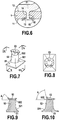
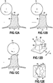
- the head of the retaining elements comprises a hooking portion extending radially relative to the upper end of the rod, said rib extending at least partially over the hooking portion.
- the head of the retaining elements comprises two hooking portions extending radially with respect to the upper end of the rod, each of said hooking portions comprising a rib, said hooking portions extending from on either side of the stem. The head can then include a rib extending continuously between the two hooking portions.
- the head further comprises a transverse rib, extending between two opposite ends of the head on either side of an axis extending in the longitudinal direction and passing through the rod and / or the head. , typically through the middle of the shank and / or the head, the transverse rib extending above the upper end of the shank.
- the at least one hooking portion comprises a free end inclined towards the base.
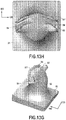
- the upper face of the head of the retaining elements comprises two distinct ribs extending at least partially over the same hooking portion.
- each of the ribs extends only over a portion of the periphery of the head, in particular the cumulative length of the ribs of a considered retention element is between 5% and 95% of the length of the periphery of the head of the retaining element considered, more particularly between 30% and 85% of the length of the periphery of the head of the retaining element considered.
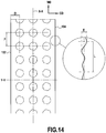
- said base comprises two edges in the longitudinal direction, and in which one of said edges has mounts and valleys, the maximum difference between mounts and valleys in a direction transverse to the longitudinal direction being less than 1mm over a length in the longitudinal direction corresponding to 3 consecutive mounts.
- the width of the base is between 1mm and 500mm, more particularly between 3mm and 100mm.
- the retaining elements have a height of between 5 to 5,000 micrometers, more particularly between 5 and 2,000 micrometers, or even more particularly between 20 and 800 micrometers, the height being measured in a direction perpendicular to the upper face. from the base.
- the rod of the retaining elements has rotational symmetry about an axis perpendicular to the upper face of the base.
- each rib of the head extends in a direction substantially transverse (namely plus or minus 30 °) to said longitudinal direction of the base.
- the retaining elements have an asymmetric geometry with respect to a plane transverse to the longitudinal direction of the base. According to one example, the retaining elements have symmetry with respect to a plane extending in a longitudinal direction of the base and passing through the axis of the rod of the retaining elements.
- This rib is arranged so as to reinforce the head of the hook, in particular the hooking portions, to facilitate the insertion and / or the passage of the fibers or filaments under the head allowing their retention.
- the height of the rib (measured in a direction perpendicular to the plane of the base) is typically between 0.005mm and 0.1mm, preferably between 0.01mm and 0.08mm.
- rib is understood to mean a longitudinal portion which extends, in its height, from the surface of the head in a direction substantially opposite to the base.
- This rib has a length (measured substantially in the longitudinal direction) greater than its width (measured substantially in the transverse direction). More particularly, the ratio of the width to the length of the rib is strictly less than 1. In other words, the rib protrudes from the top surface of the hook so that the top surface of the hook is not. flat.
- each attachment portion extends in a direction substantially perpendicular to the longitudinal direction of the base.
- each rib has, in top view of the hook, a V-shape whose angle between the two branches of the inverted V-shape (or U or C) is between 90 ° and 180 °, more particularly between 110 ° and 170 °, or more precisely between 140 ° and 150 °.
- the tip of the inverted V shape is typically located forward of the hook in the longitudinal direction.
- the length of at least one rib in a direction transverse to the longitudinal direction of the base is greater than the diameter of the rod in a direction perpendicular to the longitudinal direction of the base.
- said edges have, in sectional view in a direction transverse to the longitudinal direction, a portion of rounded shape.
- said maximum difference between the mountains and the valleys in a direction transverse to the longitudinal direction and over a length in the longitudinal direction corresponding to 3 consecutive mountains said maximum difference is between 0.001 mm and 1.0 mm, more particularly between 0.001 mm and 0.5 mm, even more particularly between 0.001 mm and 0.1 mm.
- the 3 consecutive mounts are over a distance less than the distance corresponding to 15 no hooks, preferably less than a distance of 25.0 mm.
- the width of the base measured in a direction transverse to the longitudinal direction is between 1 mm and 500 mm, more particularly between 3 mm and 100 mm.
- the retaining elements have a height of between 5 and 5000 micrometers, or alternatively between 5 and 2000 micrometers, or more particularly between 20 and 800 micrometers, or even more particularly between 100 and 500 micrometers, the height being measured according to a direction perpendicular to the upper face of the base.
- the rod of the retaining elements has rotational symmetry about an axis perpendicular to the upper face of the base.
- the retaining elements are each formed of a rod surmounted by a head, the rod comprising a lower end connected to the base, and an upper end opposite the lower end, the head surmounting the upper end. of the rod, and comprising a lower face oriented towards the base, and an upper face opposite the lower face, and in which the upper face of the head of the retaining elements comprises a rib.
- the retaining elements have an asymmetric geometry with respect to a direction transverse to the longitudinal direction of the base.
- the retaining elements have symmetry with respect to a plane extending in a longitudinal direction of the base and passing through the axis of the rod of the retaining elements.
- the base of the tape is thus free from an extra thickness extending continuously along its edges, and typically has a substantially constant thickness from edge to edge.
- a substantially constant thickness is meant a variation of less than 15% of the thickness.
- the base of the tape may be free from a non-functional extra thickness (or the sole function of which would be to improve the regularity of the edges of the tape), which is advantageous in terms of production insofar as a extra thickness leads to overconsumption of material and increases the occupancy time of the molds.
- the device further comprises a layer of nonwoven material secured to the lower face of the base and / or to the upper face of the base, and in which portions of fibers and / or filaments of the layer of material nonwoven are encapsulated in the base.
- the device further comprises a plastic film or an elastic film or a composite film secured to the lower face of the base, the surface of the film in contact with the lower face of the base being greater than the projection of the surface of the base. film on a plane defined by the underside of the base.
- said drive means comprise at least one roller.
- Said roller is typically configured to apply non-uniformly against the underside of the base, so as to provide a non-uniform bond between the base and the substrate.
- This third aspect also relates to a retaining device, comprising a plastic tape extending in the longitudinal direction comprising a base having a lower face and an upper face, and comprising a plurality of retaining elements extending from said. upper face, and a substrate secured to the underside of the base, characterized in that the substrate penetrates the base beyond a mean plane defined by the underside of the base of the tape.
- the substrate is a layer of nonwoven material, and in which portions of fibers and / or filaments of the layer of nonwoven material are encapsulated in the base.
- the substrate is a plastic film, an elastic film or a composite film, and in which the surface of the film in contact with the lower face of the base is greater than the projection of the surface of the film on a plane defined by the face. lower part of the base.
- a forming step is carried out in which the demolded strip is introduced into a forming device so as to modify the shape of the head of the second preforms by forming.
- the forming device comprises at least two rotating elements, said rotating elements each having distinct speeds with respect to the driving speed of the strip.
- the molding material is polypropylene, and in which during the forming step, at least one forming element of the forming device is maintained at a temperature between 75 and 165 ° C, in particular substantially equal at 120 ° C, or alternatively substantially equal to 140 ° C, or more precisely substantially equal to 150 ° C.
- the step of removing the tape and the first preforms from the mold causes a change in the height of the head and / or of the rod, and / or a change in width of the head and / or of the rod.
- the forming device comprises an element at ambient temperature (or at an unregulated temperature), and at least one element at a temperature strictly between the temperature of deflection under load (HDT Heat Deflection Temperature) and the temperature of melting of the molding material.
- the forming step carries out at least one deformation of a part of the head of each of the second preforms, said at least one deformation tending for each preform, to deform one of the ends of the head of the preform so forming a rib on the upper face of the head of the preform.
- the air gap between the material distribution means and the molding strip is between 10 micrometers and 700 micrometers, more particularly between 10 and 500 micrometers, or more. precisely between 50 and 100 micrometers.
- the step of distributing the molding material is carried out so that the molding material is distributed when the internal face of the molding strip bears against a roller driving the molding strip.
- the step of distributing the molding material is carried out through a nonwoven web placed on the molding strip, said nonwoven web comprising recessed areas allowing passage of the molding material.
- the molding material is then typically polypropylene or a formulation based on polypropylene, and the step of dispensing the molding material is typically carried out at a pressure of between 10 and 100 bars, or alternatively between 30 and 50 bars, and at a temperature between 150 and 300 ° C.
- the molding strip is then typically driven at a displacement speed of between 1 and 500 m / min, more particularly between 5 and 250 m / min.
- the demolding step is carried out when the base of the tape is at a temperature below the melting temperature of the molding material, or below the temperature of deflection under load of the molding material.
- the step of distributing the molding material is carried out so as to form a ribbon extending in a longitudinal direction comprising a base having two edges in the longitudinal direction, one of the edges having hills and valleys. , wherein the maximum deviation between mounts and valleys in a direction transverse to the longitudinal direction is less than 1.0 mm over a length in the longitudinal direction corresponding to 3 consecutive mounts.
- a layer of nonwoven material is applied against the lower face of the base before solidification of said lower face of the base, so as to at least partially penetrate portions of fibers and / or filaments of the layer of non-woven material in the base.
- the layer of nonwoven material is then typically at room temperature (or at an unregulated temperature), and the temperature of the base results only from the 'tape forming step.
- the underside of the base is typically at a temperature below its melting point.
- the apparatus further comprises a forming device, configured so as to modify the head of the preforms by forming.
- the apparatus further comprises means for driving a layer of nonwoven material, adapted to apply a nonwoven material against the underside of the base of the tape of retaining elements downstream of the means of material distribution.
- this apparatus further comprises a forming device, configured so as to modify the head of the preforms by forming.
- the forming device comprises at least two rotating elements, one of said rotating elements comprising heating means or temperature deregulation means configured to maintain it at a temperature strictly between the temperature of deflection under load and the temperature. melting of the molding material.
- the head may be heated prior to the forming step so that it is at a temperature between the temperature of deflection under load of the molding material and the melting temperature of the molding material.
- the forming device comprising an element rotating at a temperature, for example, below the load deflection temperature of the molding material.
- said rotating elements of the forming device each have distinct speeds relative to the molding device.
- the forming means are configured so as to produce at least one fold of the head of the preforms. More particularly, said at least one fold tends to fold at least one end of the head of the preform towards a central portion of the head of the preform.
- the forming device comprises a rotating element configured so as to operate at ambient temperature or at an unregulated temperature, and at least one rotating element comprising heating means adapted so that said at least one rotating element operates at a temperature. temperature strictly between the temperature of deflection under load and the melting temperature of the molding material.
- the rotating elements of the forming device are configured so as to be rotated at distinct rotational speeds, the rotating element having the lowest temperature has a distinct relative speed with respect to the rotating element (s).
- the cavities of the molding strips extend in a cavity direction substantially perpendicular to the external face of the molding strip, and each define a rod and a head each having rotational symmetry around said cavity direction. , the head having a dimension greater than the maximum dimension of the rod measured radially with respect to the direction of the cavity.
- the material distribution means is configured so as to distribute the molding material at a point of the molding strip when the internal face of the molding strip bears against a roller of the driving means in rotation.
- the air gap between the material distribution means and the molding strip is between 10 microns and 700 microns, more particularly between 20 and 500 microns, or more precisely between 50 and 100 microns.
- the means for driving the molding strip in rotation comprise at least two rollers each having a diameter between 10 and 10,000 times the thickness of the molding strip, in particular between 50 and 5,000 times the thickness. of the molding strip, for example between 100 and 250 mm.
- the apparatus further comprises means for applying a strip of nonwoven and / or woven and / or knitted material on the molding strip upstream of the material distribution means.
- the cavities of the molding strip open out.
- the apparatus further comprises a scraping device arranged on the internal face of the molding strip, downstream of the material distribution means.
- the molding strip comprises an internal rubber strip forming its internal face, the ends of the cavities of the molding strip being formed in said internal rubber strip.
- the first preforms are plastically deformed so as to obtain second preforms whose shape differs from the first preforms, said second preforms then being deformed by the forming device.
- the forming device comprises at least two rotating elements, said rotating elements each having different speeds relative to the strip.
- the molding material is polypropylene, and in which during the forming step, at least one forming element of the forming device is maintained at a temperature between 75 and 165 ° C, in particular around 120 ° C.
- the step of removing the tape and the first preforms from the mold causes a change in the height of the head and / or of the rod, and / or a change in width of the head and / or of the rod.
- the forming device comprises an element at ambient temperature or at an unregulated temperature, and at least one element at a temperature strictly between the temperature of deflection under load (HDT Heat Deflection Temperature) and the melting temperature of the molding material.
- the forming step carries out at least one deformation of a part of the head of each of the second preforms, said at least one deformation tending for each preform, to deform one of the ends of the head of the preform so forming a rib on the upper face of the head of the preform.
- the step of distributing the molding material is carried out so that the molding material is distributed when the internal face of the molding strip bears against a roller driving the molding strip.
- the step of distributing the molding material is carried out through a nonwoven web placed on the molding strip, said nonwoven web comprising recessed areas allowing passage of the molding material.
- the air gap between the material distribution means and the molding strip is between 10 micrometers and 700 micrometers, more particularly between 10 and 500 micrometers, or more. precisely between 50 and 100 micrometers.
- the molding material is then typically polypropylene, and the step of dispensing the molding material is typically carried out at a pressure between 10 and 100 bars, or alternatively between 30 and 50 bars, and at a temperature between 150 and 300 ° C.
- the molding strip is then typically driven at a displacement speed of between 1 and 500 m / min, more particularly between 5 and 250 m / min.
- the demolding step is carried out when the base of the tape is at a temperature below the melting temperature of the molding material, or below the temperature of deflection under load of the molding material.
- the step of distributing the molding material is carried out so as to form a ribbon extending in a longitudinal direction comprising a base having two edges in the longitudinal direction, one of the edges having hills and valleys. , wherein the maximum deviation between mounts and valleys in a direction transverse to the longitudinal direction is less than 1.0 mm over a length in the longitudinal direction corresponding to 3 consecutive mounts.
- a layer of nonwoven material is applied against the lower face of the base before solidification of said lower face of the base, so as to at least partially penetrate portions of fibers and / or filaments of the layer of non-woven material in the base.
- the layer of nonwoven material is at room temperature or at an unregulated temperature, and the temperature of the base results only from the 'tape forming step.
- the lower face of the base is at a temperature below its melting point.
- the molding strip and the mold release means are configured so that the release of the strip of preforms causes deformation of the first preforms so as to form second preforms whose shape differs from the first preforms.
- the apparatus further comprises means for driving a layer of nonwoven material, adapted to apply a nonwoven material against the underside of the base of the tape of retaining elements downstream of the means of material distribution.
- the apparatus further comprises a forming device, configured so as to modify the head of the preforms by forming.
- the forming device comprises at least two rotating elements, one of said rotating elements comprising heating means configured to maintain it at a temperature strictly between the temperature of deflection under load and the melting temperature of the material of molding.
- said rotating elements of the forming device each have distinct speeds relative to the molding device.
- the forming means are configured so as to produce at least one fold of the head of the preforms, said at least one fold tending to fold at least one end of the head of the preform towards a central portion of the head of the preform. the preform.
- the forming device comprises a rotating element configured so as to operate at ambient temperature or at an unregulated temperature, and at least one rotating element comprising heating means adapted so that said at least one rotating element operates at a temperature. temperature strictly between the temperature of deflection under load and the melting temperature of the molding material.
- the rotating elements of the forming device are configured so as to be rotated at different rotational speeds.
- the cavities of the molding strips extend in a cavity direction substantially perpendicular to the outer surface of the molding strip, and each define a rod and a head each having rotational symmetry around said cavity direction. , the head having a dimension greater than the maximum dimension of the rod measured radially with respect to the direction of the cavity.
- the material distribution means is configured so as to inject molding material at a point of the molding strip when the internal face of the molding strip bears against a roller of the driving means in rotation.
- the air gap between the material distribution means and the molding strip is between 10 microns and 700 microns, more particularly between 20 and 500 microns, or more precisely between 50 and 100 microns.
- the means for driving the molding strip in rotation comprise at least two rollers each having a diameter between 10 and 10,000 times the thickness of the molding strip, in particular between 50 and 5,000 times the thickness. of the molding strip, for example between 100 and 250 mm.
- the apparatus further comprises means for applying a strip of nonwoven material to the molding strip upstream of the material distribution means.
- the cavities of the molding strip open out.
- the apparatus further comprises a scraping device arranged on the internal face of the molding strip, downstream of the material distribution means.
- the molding strip comprises an internal rubber strip forming its internal face, the ends of the cavities of the molding strip being formed in said internal rubber strip.
- the film, the base and the retaining elements are formed integrally by successive and / or simultaneous extrusions.
- the transition between the elastic film and the base of the tape, on the side of the upper face and / or of the lower face is continuous.
- the plastic tape and the elastic film forming an intermediate layer comprising a lower face and an upper face, said device further comprising a layer of nonwoven secured to at least part of the lower face of the intermediate layer.
- the joining is then typically carried out by partial encapsulation in said intermediate layer. Partial encapsulation is typically carried out in the elastic film of said intermediate layer.
- the partial encapsulation is typically carried out in the plastic tape of said intermediate layer.
- the device further comprises a nonwoven layer secured to the upper face of the intermediate layer.
- the nonwoven layer is then typically secured to the upper face of the intermediate layer by means of glue.
- at least one of the lower face and / or the upper face of the intermediate layer has elements projecting from said face, which projecting elements are distinct from the retaining elements.
- the protruding elements typically form pins.
- the base of the plastic tape has a thickness of between 10 micrometers and 700 micrometers, the thickness being the distance between the upper face and the lower face
- the retaining elements are each formed of a rod and a head, the rod comprising a lower end connected to the base, and an upper end opposite the lower end, the head surmounting the upper end of the rod, and comprising a lower face oriented towards the base, and an upper face opposite to the lower face, and wherein the upper face of the head of the retaining elements comprises a rib.
- the nonwoven is activated. The activation of the nonwoven can be prior to the lamination or else the laminate is activated over its entire width.
- the elastic film is formed in the extension of the tape.
- a step of applying a layer of nonwoven against the lower face of the intermediate layer before solidification of said lower face of the intermediate layer is carried out, so as to make at least partially penetrate portions of fibers and / or filaments of the nonwoven layer into the intermediate layer.
- the layer of nonwoven material is then typically at room temperature or at an unregulated temperature, and the temperature of the lower face of the intermediate layer results solely from the step of producing the intermediate layer.
- the method comprises a step of applying a layer of nonwoven material against the upper face of the intermediate layer.
- the nonwoven layer is then typically bonded, typically via an adhesive, to the upper face of the intermediate layer.
- a support layer is positioned on at least part of the molding device.
- the method comprises a preliminary step of activating the layer (s) of nonwoven material.
- a molding strip having an internal face and an external face, and comprising a plurality of cavities, each cavity defining a rod extending from the external face towards the internal face, and comprising an end forming a head extending from the end of the rod towards the internal face of the molding strip
- the molding strip is positioned on rotational drive means comprising for example at least two rollers, the internal face of the molding strip being placed in abutment against the drive means, the distribution of material then being carried out by a material distribution means arranged opposite the molding strip so as to define an air gap between the material distribution means and the molding strip, the material distribution being carried out so as to filling said air gap and the cavities with molding material to form a ribbon comprising a base the thickness of which is defined by the air gap, and first preforms protruding from said base comprising a rod and a head, the first preforms being formed by the plastic material in the cavities of the molding strip, and in which the distribution of material is followed by a demoul
- a forming step is typically carried out in which the demolded tape is introduced into a forming device so as to modify the shape of the head of the second preforms by forming.
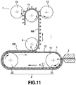
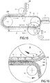
- the figure 1 shows schematically an example of an apparatus for producing a retaining device with hooks.
- the apparatus as shown comprises a molding strip 1 positioned on rotational drive means 2 here comprising two rollers 21 and 22, a material distribution means 3 adapted to perform an injection of molding material, for example plastic, and / or elastic.
- the assembly formed by the molding strip 1 and the rotary drive means 2 thus forms a molding device.
- the illustrated example comprising two rollers 21 and 22 is not limiting, the number and arrangement of the roller (s) may vary in particular in order to adapt to the length of the molding strip 1 and to the different stations of the. equipment. One could for example use three rolls or even one so that the molding strip is arranged on the periphery of the single roll.
- only one of the two rollers can be driven in rotation by motorized means, for example the roller 21, the other roller 22 being free, that is to say without motorized means, and driven in rotation via the molding strip. , itself driven by the roller 21.
- the molding strip 1 as presented comprises an internal face 11 and an external face 12, the internal face 11 being in contact with the means for driving in rotation 2.
- the material distribution means 3 is arranged so as to inject molding material on the outer face 12 of the molding strip 1. More precisely, the material distribution means 3 is arranged opposite the molding strip 1, spaced from the molding strip 1 so as to define an air gap e indicated on the figure 1 .
- the reference A indicates the limit of the material injected on the external face 12 of the molding strip 1, corresponding to the rear face of the material injected on the molding strip 1 with respect to the direction of movement of the molding strip 1 .
- the molding strip 1 is provided with a plurality of cavities allowing the hooks of the hook retaining device to be made.
- the cavities 13 are each formed so as to define a rod 14 extending from the external face 12 towards the internal face 11 of the molding strip 1 and a head 15 extending between the rod 14 and the internal face 11 of the mold. molding strip 1.
- the heads 15 of the cavities 13 open out onto the internal face 11 of the molding strip 1.
- the cavities 13 therefore pass through.
- the cavities 13 can also be blind, and therefore not open out from the internal face 11 of the molding strip 1.
- the portions of the cavities 13 forming the rods 14 typically extend in a direction perpendicular to the external face 12 of the molding strip 1.
- the portions of the cavities 13 forming the rods 14 typically have a geometry of rotation about a perpendicular axis. to the outer face 12 of the molding strip 1, or a geometry having a plane of symmetry extending in a direction parallel to the direction of travel of the molding strip 1 and / or in a direction perpendicular to the direction of travel of the molding tape 1.
- the portions of the cavities 13 forming the rods 14 have, for example, a generally frustoconical or cylindrical shape of rotation about an axis perpendicular to the outer face 12 of the molding strip 1, and having a rounding at the junction with the face outer 12 of the molding strip 1.
- the portions of the cavities 13 forming the heads 15 typically extend radially or transversely with respect to an axis perpendicular to the outer face 12 of the molding strip 1, and may have rotational symmetry about this axis perpendicular to the outer face 12 of the molding strip 1.
- the portions of the cavities 13 forming the heads 15 typically have a substantially frustoconical or hexahedral shape.
- the portions of the cavities 13 forming the heads 15 may be linear or curved, for example to form portions curved towards the internal face 11 or towards the external face 12 of the molding strip 1 extending from the portions of the cavities 13 forming the rods 14.
- the portions of the cavities 13 forming the heads 15 may have a constant or variable thickness.
- the portions of the cavities 13 forming the heads 15 extend radially around the portions of the cavities 13 forming the rods 14, and have the general shape of a disc, as can be seen in particular on the figure. figure 2 which we will present later.
- the molding strip 1 may have on its internal face 11 or on its external face 12 a particular texturing such as grooves, network of grooves or passage network forming a vent or spikes, or be substantially smooth.
- the molding strip 1 can be formed by a superposition of several strips, and is therefore not necessarily one-piece or one-piece.
- the material distribution means 3 is typically arranged so as to perform the injection of molding material into the molding strip 1 in a section of the molding strip 1 where the latter bears against a drive roller, in in this case the drive roller 21 in the example shown in figure 1 .
- the drive roller then forms a bottom for the cavities 13.
- the material distribution means 3 can then comprise a base arranged on the other. side of the molding strip 1, so that the internal face 11 of the molding strip 1 bears against the base when the material injection is carried out, the base then forming a bottom for the cavities 13 of the molding strip. molding 1.
- the molding strip 1 typically has a thickness of between 5 and 5000 micrometers, or alternatively between 5 and 2000 micrometers, or more precisely between 20 and 800 micrometers, or alternatively between 100 and 500 micrometers.
- the molding strip may have, in the longitudinal direction, a length of between 0.5 and 5 m.
- the molding strip may have, in the transverse direction, a width of between 5 and 3000 mm.
- the rollers 21 and 22 typically each have a diameter of between 10 and 10,000 times the thickness of the molding strip 1, or alternatively between 50 and 5,000 times the thickness of the molding strip 1, more precisely a diameter of between 50 and 750 millimeters, or more particularly a diameter of between 100 and 300 millimeters.
- a molding strip 1 associated with drive means 2 compared to the use of conventional forming means such as rollers in which mold cavities are directly produced is advantageous for several reasons.
- the use of a molding strip is particularly advantageous in terms of modularity.
- the molding strip can in fact be easily removed and replaced from the drive means, unlike a solid roller for which the dismantling and reassembly operations are particularly complex to perform. Such an advantage is observed particularly when the two rollers 21 and 22 are fixed to a frame on one and the same side, leaving the end of the other side free to introduce / remove the molding strip.
- a means for guiding the molding strip can also be used in order to facilitate its introduction and / or removal.
- a molding strip is greatly simplified compared to the production of a roll comprising molding cavities.
- Such rollers are in fact typically produced by stacking successive slices, therefore requiring multiple machining operations and causing significant stresses during assembly and at each change of reference of the hooks and have a significant mass requiring the maintenance of these. rollers by their two ends, which consequently complicates their replacement.
- the use of a molding strip coupled to drive means makes it possible to produce a molding device having a considerable length while maintaining simple manufacture and installation, in particular when one of the rollers is mounted to move in translation so as to modify the center distance between the rollers and thus make it possible to adjust the tension of the molding strip.
- the figure 2 shows the molding material once injected into the molding strip 1.
- the figure shows figure 2 a side view (in section) of the material in the cavities 13 of the molding strip 1.
- the molding material enters the molding strip so as to fill the cavity 13, thus forming a rod and head blank for hooks.
- a layer of molding material is also deposited on the outer face 12 of the molding strip 1 so as to form a base for the retainer, the thickness of this layer of molding material being determined by the air gap e between the material distribution means 3 and the molding strip 1.
- the air gap e typically has a thickness of between 10 and 700 micrometers, or typically between 10 and 500 micrometers, or alternatively between 20 and 100 micrometers.
- the cavities 13 of the molding strip 1 pass through.
- the apparatus can then comprise an element such as a doctor blade 4 positioned so as to scrape the internal face 11 of the molding strip 1 in order to remove the excess molding material if necessary.
- injection is meant the action of shaping a molten molding material, for example, dispensing, supplying, molding, injecting, extruding.
- the injection of molding material into the molding strip 1 by the material distribution means 3 therefore makes it possible to form a base 51 and a plurality of elements or preforms each comprising a rod 52 and a head 53, the assembly thus forming a tape 100.
- the elements comprising the rods 52 and the heads 53 are typically first preforms which will then be subjected to a forming step for the production of the hooks.
- a longitudinal direction is defined with respect to the direction of movement of the tape 100, this longitudinal direction being parallel to the direction of movement of the tape 100.
- This longitudinal direction is commonly referred to as “machine direction” or “machine direction” or “MD”. according to the name in English.
- the longitudinal direction is denoted by the axis MD in the figures.
- the base 51 has an upper face 511 and a lower face 512 which are typically substantially parallel, the upper face 511 being the face provided with hooks and / or preforms.
- the base 51 typically has a thickness of between 10 and 700 micrometers, or typically between 20 and 500 micrometers, or alternatively between 50 and 100 micrometers.
- the base 51 typically has a width of between 1 and 3000 millimeters, or more precisely between 2 and 400 millimeters, or alternatively between 3 and 100 millimeters, the width of the base 51 being measured according to the direction transverse to the longitudinal direction, for example in a direction parallel to the outer face 12 of the molding strip 1.
- the figures 3, 4 and 5 illustrate three views of the hook preforms thus formed by injection of material into the molding strip 1, respectively in perspective view, in top view and in sectional view. It will be understood that these are representations of the molding material within the cavities 13, each shown isolated from the molding strip 1 in order to detail the shape thereof.
- the hook preforms thus formed here the first preforms, have a rod 52 of generally cylindrical or conical shape surmounted by a head 53.
- a rod 52 of generally cylindrical or conical shape surmounted by a head 53.
- the head 53 extends from the upper end 522 of the rod 52.
- the head 53 has the shape of a hexagon, the edges of which form arcs of a circle.
- the head 53 therefore comprises a plurality of portions extending radially from the upper end 522 of the rod 52.
- Several other shapes of head 53 can be envisaged; the example illustrated is only intended to illustrate one embodiment.
- the head 53 may in particular have a hexagonal shape.
- the apparatus as presented and the associated method allow operation at high tape forming speeds.
- conventional production lines for making hook retainers operate at reduced forming speeds, these low forming speeds being compensated by the widening of the formed strip.
- This limitation in terms of formation rate results in particular from the time required for the solidification of the injected material.
- the installation and the method as presented make it possible, on the contrary, to form a ribbon with a high forming speed, for example greater than 20 meters per minute, or even greater than 40, 60, 80, 100, 120 or 150 meters per minute. , or between 1 and 500 meters per minute, or alternatively between 5 and 250 meters per minute.
- the method presented does not in fact require complete cooling of the injected material for the formation of the hooks, and moreover, the use of a low thermal inertia molding strip which can have through cavities makes it possible to considerably improve the speed. solidification of the tape.
- the injection of molding material by the material distribution means 3 can be carried out through a sheet of non-woven material placed on the outer face 12 of the molding strip 1.
- a web of nonwoven material is then placed on the outer face 12 of the molding strip 1 upstream of the material distribution means 3.
- This web of nonwoven material may have recessed areas facilitating the passage of the molding material, and also areas preventing the passage of molding material.
- Such an embodiment thus makes it possible to obtain a tape having a layer of nonwoven material on its upper face, that is to say on its face having the retaining elements, that is to say the hooks.
- the injection of the molding material directly onto the sheet of nonwoven material then makes it possible to ensure a strong cohesion of the nonwoven material with the base 51.
- a pattern can be defined for the distribution of the hooks.
- the substrate in the calibrated zone typically exhibits an air permeability greater than 2000 l / m2 / sec, more particularly, greater than 4000 l / m2 / sec in the area where the hooks pass.
- This permeability characteristic is either intrinsic to the substrate, or related to the substrate by treatment, drilling, punching, needling, suction, embossing or the like.
- the substrate can be a nonwoven material, for example a printed nonwoven material.
- the permeability of the substrate is for example measured according to the ISO 9237 STANDARD of 1995 with a pressure of 200Pa and circular specimens of 20 cm 2 .
- the basis weight of this nonwoven material is typically between 2 g / m 2 and 45 g / m 2 .
- the permeability may be less than 15,000 l / m 2 / sec, or even less than 7,500 l / m 2 / sec.
- the nonwoven material used is typically a nonwoven with a thickness between 0.10 and 0.8 mm, in particular between 0.20 and 0.60 mm.
- the thickness of the nonwoven material is measured for example according to standard NF EN ISO 9073-2 of 1997 using method A for normal nonwovens with a pressure of 0.5 kPa and for a period of 10 s.
- the nonwoven material may also locally have low mechanical strength or intrinsically low mechanical strength so that the nonwoven material is perforated by the molding material when making the hooks or preforms.
- the material distribution means 3 can be adapted to distribute simultaneously or successively at least two distinct materials, thus making it possible to define two zones made of two distinct materials in the strip 100. More precisely, the material distribution means 3 can be adapted to simultaneously inject a molding material such as polypropylene for the formation of the base 51 and the hooks, and of an elastic material making it possible to form an elastic profile in the extension base 51.
- the molding strip 1 can then have shapes suitable for the different zones of the strip 100, for example have a portion provided with cavities 13 for the formation of preforms or hooks corresponding to the portion into which the molding material is injected, and a portion not having such cavities 13 corresponding to the portion where the elastic material is injected.
- the figure 6 schematically shows the release of the tape 100 formed previously.
- the portions of the cavities 13 forming the rods 14 and the heads 15 are thus dimensioned so as to allow the heads 53 to pass through the portions of the cavities 13 forming the rods 14 in order to perform demolding.
- the demolding therefore causes a deformation of the heads 53, which is shown schematically on the figure 6 .
- This deformation can be elastic and / or plastic in nature, and can therefore lead to a modification of the heads 53 and of the rods 52 in the event of plastic deformation, or the heads 53 and rods 52 can return to their initial shape after demoulding in the event of deformation.
- elastic The nature of the deformation depends in particular on the material used, but also on the geometry of the heads 53 and of the rods 52.
- demolding is typically carried out in a zone in which the molding strip is not in contact with one of the rollers 21 and 22.
- a deformation of the head 53 is shown diagrammatically which passes from a generally planar shape to a corolla shape, the portions of which extending radially or transversely from the upper end 522 of the rod 52 therefore pass from a substantially planar configuration to an inclined configuration in a direction opposite to the base 51.
- the perimeter of the free end of the head 53 typically remains unchanged.
- the figure 7 is a perspective view of a portion of tape 100 thus removed from the mold
- the figure 8 is a top view
- the figures 9 and 10 are two sectional views along two perpendicular planes marked on the figure 7 .
- the head 53 after demoulding has an asymmetric shape; the orientation of the force during demolding in fact causes distinct deformations on the different portions of the head 53. As shown in FIG.
- the portion of the head 53 positioned at the front (relative to the direction of travel of the molding strip 1) of the preform is here more raised than the portion of the head 53 positioned at the rear (relative to the direction advance of the molding strip 1) of the preform, that is to say that the inclination of the portion of the head 53 positioned at the front of the preform has been changed by an angle greater than the angle of which the inclination of the portion of the head 53 positioned at the rear of the preform has been modified.
- the head 53 can be made so as to have a symmetrical shape after demolding. This deformation of the head 53 causes the formation of a flared collar around a central portion of the head 53.
- This collar has variations in thickness, for example a thickness which becomes thinner as it moves away from the rod 52. Compared to the rod 52, the distal end of the collar has a thickness less than the proximal end of the collar. These variations in thickness make the mechanical action of the folding easier and reduce the thermal inertia necessary for its deformation in a subsequent step, for example during the folding and / or forming which is described below. More particularly, at least a portion of the flange thus formed has in section view an angle A of at least 15 ° between the mean axis of the portion in question of said flange and a plane parallel to that of the base 51. More particularly, this angle is greater than 35 °, even more particularly greater than 45 °.
- the angle A as shown is substantially equal to 55 ° and on the figure 10 , the angle A is substantially equal to 80 °. Due to the formation of the collar, the maximum dimension of the head of the first preform measured in a plane parallel to the plane of the base 51 (which is referred to as the width of the head) is reduced from 10% to 150% , or else from 25% to 100% relative to the head width of the second preform and / or the diameter of the rod of the second preform.
- the height of the head of the second preform is increased from 5% to 100%, or even from 12% to 50% relative to the height of the head of the first preform, the height being measured in a plane perpendicular to the plane of the base 51.
- the width of the head is reduced from 0.05mm to 0.2mm for a diameter of the rod of the order of 0.2mm, the diameter of the rod of the first and second preform being substantially identical.
- the height of the head is increased from 0.025mm to 0.1mm for a diameter of the rod of the order of 0.2mm, the diameter of the rod of the first and second preform being substantially identical.
- the step of injecting the molding material into the molding strip 1 forms first preforms for the hooks each comprising a rod 52 and a head 53 (as shown for example in the figures 2 to 5 ), and that these first preforms are then plastically deformed during demolding so as to form second preforms whose shape differs from the first preforms, as shown for example on the figures 6 to 10 .
- plastic deformation is meant a residual or remanent deformation after elongation and relaxation.
- demolding is carried out by means of a demolding roller 6, typically configured so as to separate the base 51 of the tape 100 from the molding strip 1 under the effect of the tension of the tape and of its change in direction.
- the mold release roller can be equipped with a suction means and / or a surface with a high coefficient of friction, such as for example a rubber coating in order to improve the drive and limit slippage.
- This release roller can be motorized and have a tangential speed slightly greater than that of the strip.
- the separation between the tape 100 and the molding strip 1 is marked in the figures by the reference C, this point corresponding for example to the level from which the base 51 of the strip 100 is no longer in contact with the molding strip 1. Provision can be made for the molding strip 1 to embed on the mold release roller 6, that is to say that the mold release roller 6 forms a lever in the molding strip 1 to facilitate the release of the preforms and / or hooks. .
- the first or second preforms can then be adapted to perform a function of retaining means, or conversely not to have such properties.
- Demolding is typically carried out when the base 51 of the tape 100 is at a temperature below the melting temperature of the molding material, or below the temperature of deflection under load of the molding material, for example when the internal face 11 of the molding material.
- molding strip 1 is at a temperature of the order of 45 ° C and the upper face 511 of the base 51 is at a temperature of the order of 75 ° C.
- the deflection temperature under load is commonly referred to by its designation in English as “Heat Deflection Temperature” or “HDT”.
- the demolding step can be followed by a forming step, in which the second preforms are modified in particular at their head 53.
- the apparatus shown in figure 11 is similar to the one already shown on the figure 1 , but also comprises a forming device 7 positioned downstream of the mold release roller 6.
- the forming device 7 as presented comprises a drive roller 71 and two forming rollers 72 and 73.
- the driving roller 71 has the function of guiding and driving the tape 100.
- the forming rollers 72 and 73 have the function of performing a forming action on the rods 52 and / or the heads 53 of the preforms obtained from the demolding. .
- the forming device 7 comprises two forming rollers 72 and 73, making it possible to carry out two successive forming steps that described below.
- the forming device 7 is not limited to such an embodiment, and can comprise a variable number of rollers or more generally of forming means in order to carry out the desired forming steps.
- the forming device 7 can be configured so as to perform only a single deformation, and then only include a single forming roll.
- the forming rollers 72 and 73 are configured to exert a mechanical and / or thermal force on the heads 53 as well as on the rods 52 of the preforms, so as to cause a plastic deformation in order to give a final shape to the hooks.
- the tape 100 is driven by the driving roller 71 of the forming device 7.
- the forming rollers 72 and 73 are arranged so as to each define a passage between the forming roller in question and the driving roller 71 allowing the passage of the tape 100.
- These passages between the drive roller 71 and the forming rollers 72 and 73 are dimensioned so as to have a dimension less than the height of the strip 100, or where appropriate the height of the strip 100 and of the substrate, so as to that the forming rollers 72 and 73 exert a force on the preforms.
- the two forming rollers 72 and 73 will allow two successive stages of deformation of the preforms to be carried out.
- the forming rollers 72 and 73 are each rotated at speeds of rotation distinct from that of the drive roll 71, and therefore also distinct from the running speed of the tape 100.
- the first forming roll 72 has a tangential speed lower than that of the drive roll 71, for example between 5 and 200% lower than that of the drive roll.
- the second forming roller 73 typically has a tangential speed greater than that of the roller drive 71, for example 5 and 200% greater than that of the drive roller 71, or alternatively between 10% and 80% greater than that of the drive roller 71.
- the forming rolls 72 and 73 are each typically maintained at a predetermined temperature depending on the molding material, for example between 75 and 165 ° C or more particularly substantially equal to 120 ° C for a tape formed from polypropylene, while that the drive roller 71 is maintained at room temperature or at an unregulated temperature or at a temperature below the temperature of deflection under load, for example below 65 ° C.
- the figures 12a to 12e thus illustrate the deformation of a preform after action of the first forming roller 72.
- the direction of rotation of the forming roller 72 and the direction of travel of the tape 100 are illustrated diagrammatically by arrows.
- the preform as considered is that presented previously with reference to figures 7 to 10 .
- the forming roll 72 crushes and deforms a portion of the head 53.
- the forming roll 72 comes into contact with a portion of the various portions of the head 53 extending from the upper end 522 of the rod 52, and brings them back towards the central region of the head 53.
- This deformation of the preform causes a partial softening of the portion brought back towards the central region of the head 53 with the material of the central region of the head 53, and also the formation of a substantially planar inclined region on one face of the head 53.
- the figure 12c schematically shows the preform after the action of the forming roller 72.
- the figures 12d and 12e present two other views, respectively in perspective and in top view of such a preform thus deformed.
- the forming roller 72 has produced a deformation on a front of the preform, here the front of the preform with respect to the direction of travel.
- This deformation leads to the formation of a rib extending in a direction substantially transverse to the longitudinal direction of the strip 100.
- the deformation action exerted by the forming roller 72 causes a return of a portion of the head 53 of the preform corresponding to the front of the preform according to the direction of travel, but this deformation action causes a flattening of the portions of the preform.
- head of the preform 53 extending in the direction transverse to the direction of travel, thus forming fins extending on either side of the rod 52 in the direction transverse to the direction of travel of the tape 100. These fins define hooking portions 54 of the head 53, extending radially beyond the rod 52 of the preform, from the upper end 522 of the rod 52.
- the deformation produced by the forming roller 72 forms a first rib 81 extending at least partially over the hooking portions 54. More generally, the deformation produced by the forming roller 72 causes the formation of a hooking portion 54 and of a rib extending at least partially over the hooking portion 54. The rib thus formed extends over the upper face of the head 53, thus providing a mechanical reinforcement of the head 53.
- the forming can then result in the formation of a single rib extending continuously between the hooking portions 54, or several disjointed ribs each extending to the less partially on one or more of the attachment portions 54.
- a second deformation can be achieved by the forming roll 73.
- the figures 13a to 13j schematically show the deformation of the preform by the forming roll 73, and the shape of the resulting hook. We now speak of a hook once the preforms have been subjected to these forming steps.
- the figures 13a and 13b represent the deformation of the preform by the forming roll 73.
- the forming roll 73 is configured to come into contact with a front portion of the preform with respect to its direction of movement, and deform the head 53 of the preform.
- the parameters of temperature and speed of rotation of the forming roll 73 cause the material of the head 53 of the preform to adhere, making it possible to straighten a part of the head 53 protruding from the rod 52.
- the forming roll 73 has an identical direction of rotation with respect to the forming roll 72 described above, and has a tangential speed greater than the tangential speed of the drive roll 71 .
- the forming roller 73 deforms the head 53 of the preform so as to cause the material of the head 53 towards the front of the preform (relative to its direction of movement). Therefore, the forming roll 72 performs a first deformation of the preform tending to bring the material back from the front of the preform towards the central part of the head 53, while the forming roll 73 performs a second deformation of the preform. preform tending to bring the material towards the front of the preform.
- the first rib 81 formed previously is therefore brought back towards the front of the preform, and extends beyond the rod 52 of the preform.
- the first rib thus modified is identified by the reference 81 ′ in the figures. For the sake of readability, reference will be made throughout the text to the first rib by the reference 81.
- a second substantially transverse rib 82 is formed, also extending between two transverse ends of the hook, here formed by the hooking portions 54.
- the hook thus formed comprises a first rib 81 resulting both from the action of the first forming roll 72 and from the action of the second forming roll 73, and a second rib 82 resulting from the action of the second forming roll. forming 73.
- These two ribs 81 and 82 each extend between two opposite ends of the hook in the transverse direction, that is to say between the two hooking portions 54 in the example shown.
- the first rib 81 extends substantially along the front face of the hooking portions 54
- the second rib 82 extends substantially along the rear face of the hooking portions 54.
- the hooking portions 54 thus typically comprise two distinct ribs extending at least partially over the hooking portion considered.
- the hooking portions 54 and the first and second ribs 81 and 82 thus define transverse ends of the hooks having a substantially U shape with a substantially planar base and the two ribs of which extend in a substantially perpendicular direction.
- the ribs 81 and 82 therefore make it possible to produce a mechanical reinforcement of the hooking portions 54, the latter being configured so as to cooperate with complementary elements such as other hooks or loops in order to form a retaining system.
- the term “mechanical reinforcement” is understood here to mean the fact that the hook is less able to deform, under the action of the same force, with such a rib or such ribs, than a similar hook without such a. rib.
- the hooking portions 54 can extend substantially radially relative to the rod 51, or have a free end inclined towards the base 51 as visible for example on the figures 13e , 13i or 13d , which improves the retaining properties of the hook.
- the rib (s) 81 and 82 each extend over only a part of the head 53.
- the ribs thus typically extend over only a part of the periphery of the head 53.
- the ribs typically have a cumulative length of between. between 5 and 95% of the length of the periphery of the head 53, or more precisely between 30 and 70% of the length of the periphery of the head 53.
- the periphery of the head 53 is here considered to be the radial periphery of the head 53 after the step of forming the hooks or during its formation in the molding strip 1.
- At least one of the ribs 81 and 82 here typically has a length greater than the diameter of the rod 52, the diameter being measured in a direction transverse to the longitudinal direction.
- the ribs 81 and 82 have, in top view of the hook, each in the general shape of an inverted V (or U or C) comprising two branches forming an angle, this angle typically being between 90 ° and 180 °, or more precisely between 110 ° and 170 °, or alternatively between 140 ° and 150 °, or else substantially equal to 145 °.
- the two branches of the general V-shape of the rib here converge towards the front of the hook.
- This embodiment is illustrative only, and the general V-shape can be reversed so that the rib converges towards the rear of the hook, for example by modifying the speed parameters of the forming device 7.
- the tip of the inverted V shape, or where appropriate the top of the U or C, may be forward in the longitudinal direction.
- the ribs 81 and 82 typically exhibit symmetry with respect to a plane extending in a longitudinal direction of the base 51, passing through a central axis of the rod 52 of the retaining elements.
- the hooks thus formed typically have a height of between 5 to 5000 micrometers, or alternatively between 5 and 2000 micrometers, or more particularly between 20 and 800 micrometers, or even more particularly between 100 and 500 micrometers, the height being measured in a perpendicular direction. to the upper face 511 of the base 51.
- the head 53 can be heated prior to the forming step so that it is at a temperature between the temperature of deflection under load of the molding material and the melting temperature of the molding material, the forming device. 7 comprising an element rotating at a temperature, for example, lower than the load deflection temperature of the molding material.
- the hook has a substantially planar inclined region on the face of the head arranged at the rear of the hook (relative to the direction of travel of the molding strip 1).
- Another aspect of the device as presented relates to the evenness of the ribbon thus produced.
- the injection of molding material by the material distribution means 3 in fact makes it possible to obtain a tape having edges in the longitudinal direction that are substantially straight as soon as the tape is produced, without requiring an additional cutting step.
- tape 100 As described above in top view, which tape comprises a base and here preforms or hooks.
- the tape 100 is shown provided with preforms as already described in particular with reference to figures 7 to 10 .
- This figure schematically shows the tape 100 obtained following the injection of material into the molding tape 1, this tape therefore extending in a longitudinal direction identified by an axis XX on the figure 14 .
- the longitudinal direction identified by the axis XX is here parallel to the machine direction, that is to say the direction of drive of the tape 100.
- Two edges 102 and 104 are defined for this tape 100 each extending in the longitudinal direction, these two edges 102 and 104 defining the two ends of the tape 100 in a transverse direction perpendicular to the longitudinal direction.
- the hooks or preforms are generally arranged near the edges 102 and 104.
- the hooks or preforms are typically arranged at a distance D from the edges 102 and 104 of between 2 and 3 pitches P of hooks, typically equal to 2 or 3 pitches P of hooks, the distance D being measured in the transverse direction with respect to the longitudinal direction materialized by the axis XX on the figure 14 .
- the pitch P between two hooks corresponds to the distance between two successive hooks in the longitudinal direction.
- the hooks or preforms are arranged in columns extending in the longitudinal direction materialized by the axis XX, these columns being repeated identically in the transverse direction.
- the hooks or preforms can also be arranged in a staggered or “honeycomb” arrangement, for example by shifting the columns of hooks or preforms in the longitudinal direction.
- each of the edges 102 and 104 has a succession of mountains and valleys, said succession extending in the longitudinal direction and said mountains and valleys extending in a plane parallel to that formed by the base 51, these mountains and valleys translating slight irregularities in the distribution of molding material for forming the tape 100, it being understood that a perfectly straight edge is not industrially feasible.
- Valleys are understood to be the regions of edges 102 and 104 protruding inwardly from tape 100 while mounts are understood to be regions of edges 102 and 104 protruding outwardly from tape 100.
- the regularity of the edges edges 102 and 104 can therefore be assessed using these successive mountains and valleys.
- the edges 102 and 104 have, in sectional view in a direction transverse to the longitudinal direction, a portion of rounded shape. More particularly, the rounded shape is oriented to the lateral exterior of the base. This rounded shape is carried out during the formation of the base. In other words, this rounded shape was not obtained by cutting.
- edges 102 and 104 of the tape such that for a length L in the longitudinal direction corresponding to three consecutive mountains, the maximum distance E between the mountains and the valleys according to a direction transverse to the longitudinal direction is less than 3.0 mm, or more precisely less than 2.0 mm, or even more precisely less than 1.0 mm, or even between 0.001mm and 1.0mm, more particularly between 0.001 mm and 0.5mm, even more particularly between 0.001mm and 0.1mm.
- Such a definition is also applicable for a length corresponding to three consecutive valleys; the maximum difference between mountains and valleys in a direction transverse to the longitudinal direction is less than 3.0 mm, or more precisely less than 2.0 mm, or even more precisely less than 1.0 mm, or even included between 0.001mm and 1.0mm, more particularly between 0.001mm and 0.5mm, even more particularly between 0.001mm and 0.1mm.
- the 3 consecutive mountains or valleys are typically over a distance less than the distance corresponding to 15 pitches of hooks, preferably less than a distance of 25 mm.
- edges 102 and 104 that can thus be qualified as “straight” is advantageous in that it makes it possible to dispense with a subsequent step of rectifying the edges, for example via a cutting step, of cutting. such straight edges being perceived by the user as a sign of product quality.
- the apparatus and the method employed make it possible to obtain such straight edges without requiring the formation of longitudinal excess thicknesses at the edge of the tape, such excess thicknesses not having any functional interest.
- the base 51 of the tape 100 can thus be free from an extra thickness extending continuously along its edges, and typically has a substantially constant thickness from one edge to the other. More generally, it is understood that the base 51 of the tape may be free from a non-functional extra thickness (the sole function of which would be to improve the regularity of the edges of the tape), which is advantageous in terms of production insofar as the Thicknesses lead to overconsumption of material and increase the occupancy time of the molds.
- the straight edges are obtained via the injection of the molding material by the material distribution means 3.
- the subsequent demolding and forming steps keep these straight edges as described above, in insofar as these steps do not entail the application of forces on the edges of the base 51 of the tape 100.
- the tape 100 thus obtained at the end of these various steps therefore has a straight edge as defined above.
- the interface between the two materials is then typically produced so as to have a straight demarcation, as described above. with reference to the edges of the base 51 of the tape 100.
- each material is injected by the material distribution means 3 so as to form straight edges at both ends cross sections of the strip of material thus formed. Consequently, the junction between the two materials is a junction between two straight edges as defined above, and therefore has a profile which is qualified as straight according to the definition established above.
- the dispensing means may, for example, comprise two injection or extrusion nozzles.
- the apparatus presented above and the associated method can also have means and a step of associating a substrate with the tape.
- Such an association of a substrate on a tape comprising gripping elements is typically achieved by means of an adhesive, or by fusing the base or the substrate, as mentioned previously.
- the proposed equipment may include substrate driving means, suitable for providing a supply of substrate and for applying the substrate against the lower face 512 of the base. 51 of the tape 100 downstream of the material distribution means 3.
- the apparatus as presented comprises substrate driving means 9, here constituted by two rollers 91 and 92, configured to provide a supply of substrate 200 downstream of the material distribution means 3.
- the substrate 200 is typically a layer of nonwoven material, a plastic film, an elastic film or a composite film, or even a set of fibers and / or filaments consolidated thermally.
- the substrate 200 is for example a sheet of fibers and / or filaments. In the example shown on figures 15 and 16 , the substrate is shown as a layer of non-woven material.
- nonwoven a product obtained at the end of the formation of a web of fibers and / or filaments which have been consolidated. Consolidation can be mechanical, chemical or thermal and results in the presence of bond between fibers and / or filaments. This consolidation can be direct, that is to say made directly between the fibers and / or filaments by welding, or it can be indirect, that is to say through an intermediate layer between the fibers. and / or the filaments, for example a layer of glue or a layer of binder.
- nonwoven refers to a sliver or web-like structure of fibers and / or filaments which are interwoven in a non-uniform, irregular or random manner. A nonwoven can have a single layer structure or a multiple layer structure.
- a nonwoven can also be joined with another material to form a laminate.
- a nonwoven can be made from different synthetic and / or natural materials.
- Exemplary natural materials are cellulose fibers, such as cotton, jute, linen and the like, and can also include re-processed cellulose fibers, such as rayon or viscose.
- Natural fibers for a nonwoven material can be prepared using various methods such as carding.
- Exemplary synthetic materials include, but are not limited to, synthetic thermoplastic polymers, which are known to form fibers which include, but are not limited to polyolefins, for example polyethylene, polypropylene, polybutylene and similar; polyamide, for example polyamide 6, polyamide 6.6, polyamide 10, polyamide 12 and the like; polyesters, for example polyethylene terephthalates, polybutylene terephthalates, polylactic acids and the like, polycarbonates, polystyrenes, thermoplastic elastomers, vinyl polymers, polyurethanes and mixtures and co-polymers thereof.
- synthetic thermoplastic polymers which are known to form fibers which include, but are not limited to polyolefins, for example polyethylene, polypropylene, polybutylene and similar; polyamide, for example polyamide 6, polyamide 6.6, polyamide 10, polyamide 12 and the like; polyesters, for example polyethylene terephthalates, polybutylene terephthalates, polylactic acids and the like, polycarbonates, polys
- the nonwoven can be a nonwoven of the Spunbond, Spunmelt, thermo-bonded carded, SMS, SMMS, SS, SSS, SSMMS, SSMMMS, Air through or other type.
- the substrate is not limited to a nonwoven, and may more generally be a nonwoven, a woven material, a knitted material, or a combination of several of these materials.
- the substrate driving means 9 are configured to supply the apparatus with substrate 200, and apply this substrate 200 against the lower face 512 of the base 51 of the strip 100 downstream of the material distribution means 3.
- the substrate driving means 9 are configured so that this application is carried out prior to the solidification of the base 51 of the strip 100.
- this application leads to at least partial penetration of the substrate 200 beyond one. plane defined by the lower face 512 of the base 51 of the strip 100.
- the reference B in the figures is marked with the point of contact between the base 51 of the strip 100 and the substrate 200. More precisely, the lower face 512 of the base 51 is substantially planar, and defines a plane.
- the application of the substrate against this face causes a penetration of portions of the substrate 200, for example of fibers and / or filaments of the layer of nonwoven material in the case where the substrate 200 is a layer of nonwoven material within of the base 51, thereby passing through the lower face 512 of the base 51.
- figure 17 an example of a product resulting from this joining between the tape 100 and the substrate 200.
- an application is carried out prior to the solidification of the base 51 of the tape 100, it is not necessary to heat the base 51 of the tape 100 and / or the substrate 200 in order to achieve such a bond.
- the application of the substrate against the lower face 512 of the base 51 is typically carried out when the lower face 512 of the base 51 has a temperature between the melting point of the material and the Vicat B softening temperature of the material constituting it minus 30 ° C. or alternatively between the melting temperature of the material constituting it and the Vicat A softening temperature of the material constituting it.
- the lower face 512 of the base 51 has a temperature of between 75 ° C and 150 ° C, typically of the order of 105 ° C, this temperature typically being measured. by means of an infrared or laser camera.
- VICAT softening temperature is understood to mean the temperature obtained according to one of the methods described in the ISO 306 or ASTM D 1525 standards with a heating rate of 50 ° C / h and a standardized load of 50N for VICAT B and a load standardized to 10N for VICAT A.
- the lower face 512 of the base 51 is at a temperature lower than its melting temperature, or more particularly lower than the deflection temperature under load of the material forming the base 51, or else substantially equal to the ambient temperature (or at an unregulated temperature), and the temperature of the base 51 is resulting only from the step of forming the tape 100.
- the distance traveled by the base 51 between the points A and B is typically between 20.0 mm and 400 mm.
- the distance traveled by the base 51 between points B and C is typically between 400 mm and 1500 mm.
- the distance traveled by base 51 between points B and C is typically twice the distance traveled by base 51 between points A and B.
- Roll 92 is typically configured so as to pressurize substrate 200 against underside 512 of base 51 in order to facilitate penetration of substrate 200 into base 51.
- the roller 92 may have patterns or reliefs on its surface, so as to promote the penetration of the substrate 200 into the base 51.
- the substrate 200 can be applied in a uniform or non-uniform manner against the lower face 512 of the base 51.
- the connection made between the substrate 200 and the base 51 of the tape 100 can be made in a uniform or non-uniform manner.
- the bond with the base 51 is also achieved by penetrating into the base part of the fibers and / or filaments of the substrate 200.
- the bond with the base may then result in a phenomenon of shrinkage of the tape 100 during its cooling, this shrinkage promoting the bonding surface between the substrate and the base of the tape.
- This shrinkage has no impact on the visual appearance for the end user. More precisely, it is well known that molded parts exhibit a phenomenon of shrinkage or shrinkage during cooling of the material.
- the strip 100 has portions of distinct thicknesses due to the presence of the retaining elements extending from the upper face 511 of the base 51. These zones having an excess thickness will lead to phenomena of shrinkage of the material to be removed.
- the substrate 200 remains in contact with the lower face 512 of the base 51, and the regions of the film forming the substrate 200 therefore match the shape of the material withdrawal zones in the lower face 512 of the base 51. These regions of the film forming the substrate 200 therefore penetrate beyond the plane defined by the lower face 512 of the base 51.
- the surface of the film forming the substrate 200 in contact with the lower face 512 of the base 51 is greater than the projection of the surface of the film onto a plane defined by the lower face 512 of the base 51, which makes it possible to increase the adhesion between the substrate 200 and the tape 100.
- the release of the hooks is carried out easily even with a nonwoven whose basis weight is less than 80 gsm.
- the basis weight of the nonwoven may be between 5gsm and 120gsm, or alternatively between 10gsm and 70gsm.
- the apparatus may comprise a calendering device upstream of the substrate driving means 9, thus making it possible to carry out a calendering step locally or not of the layer of non-woven material prior to its application against the tape 100.
- This method of securing a substrate 200 to a tape 100 is in particular advantageous in that it does not cause deformation of the tape 100, and therefore advantageously makes it possible to retain the shape of the base 51 obtained during step d. injection, and in particular to keep the straight edges obtainable by the method and the apparatus described above.
- This method of securing a substrate to a tape can be applied to a method for forming a tape as described above, or more generally to any other method for forming a tape comprising retaining elements such as hooks. .
- the figure 18 thus presents a product 300 comprising a tape 100 made of plastic material, the tape 100 is formed integrally with a film of elastic material 310 by extrusion. More particularly, the tape 100 made of plastic material is formed integrally with a film of elastic material 310 by simultaneous or successive extrusions.
- the term “successive extrusions” is understood here to mean the fact that the film 310 and / or the tape 300 is produced in the continuity of the formation of the tape 300 and / or the film 310, or else on the same production line.
- the figure 18 is a sectional view along a plane perpendicular to the longitudinal direction of the product 300 formed.
- the tape 100 is similar to the tape as described above, and includes a base 51 and hooks extending from the top face 511 of the base 51.
- the film of elastic material 310 was extruded simultaneously, successively or prior to the extrusion of the tape 100 by the material distribution means 3, thus defining a connection between the tape 100 and the film 310 according to one of their transverse ends.
- the transition between the elastic film 310 and the base 51 of the tape 100 is thus typically continuous.
- the film of elastic material 310, the base and the retaining elements of the tape 100 of plastic material are made in one piece and obtained from extrusion.
- Reference numeral 320 denotes the interface between the film of elastic material 310 and the tape 100.
- in one piece is meant the fact that the tape and the film are linked only by simultaneous or successive material distributions, for example by simultaneous or successive extrusion.
- the bond obtained is achieved only by intramolecular diffusion from the tape to the elastic film and / or from the elastic film to the tape.
- This interface 320 can be produced in a plane substantially parallel to the longitudinal direction of the product 300 as shown in the figure. figure 18 , or provide an overlap between the elastic film 310 and the tape 100.
- the hooks and the base are formed from the same material, it can be seen that there is a continuity of the material from the base to the hooks and vice versa. In other words, the material forming the hooks and the material forming the base are contiguous.
- an upper face 311 and a lower face 312 are defined.
- the upper face 311 of the elastic film 310 is here in the extension of the upper face 511 of the base 51 of the tape. 100.
- the lower face 312 of the elastic film 310 is here in the extension of the lower face 512 of the base 51 of the tape 100.
- the assembly formed by the elastic film 310 and the tape 100 thus constitutes an intermediate layer, having a lower face and an upper face.
- a substrate 200 is secured to the lower face of the intermediate layer, that is to say to the lower face 312 of the elastic film 310 and to the lower face 512 of the base 51 of the tape 100.
- the substrate 200 is for example a nonwoven material, as described above.
- the substrate 200 is secured to the intermediate layer by partial encapsulation in said intermediate layer, that is to say by partial encapsulation of the substrate in the base 51 of the tape 100 and in the elastic film 310. This securing is carried out via the method. and the apparatus already described previously with reference to figures 15 to 17 .
- the product 300 as presented also comprises a support layer 330 secured to the upper face of the intermediate layer.
- This support layer 330 extends over the upper face 311 of the elastic film 310, and also at least partially on the upper face 511 of the base 51 of the tape 100.
- the support layer 330 can be of identical composition to the substrate 200, or of a different composition; it may for example be a layer of nonwoven material, a knitting or a grid.
- the support layer 330 is secured to the upper face of the intermediate layer by gluing.
- a layer of adhesive 340 extending on the upper face 311 of the elastic film 310 and also partially on the upper face 511 of the base 51 of the tape 100.
- the support layer 330 is then typically secured to the upper face of the intermediate layer after the substrate 200 has been secured to the lower face of the intermediate layer. It is well understood that this method of joining is only illustrative, and that any other suitable method can be used to join the support layer 330 on the upper face of the intermediate layer.
- the support layer 330 can for example be placed on the molding strip 1 prior to the distribution of material by the material distribution means 3, so that the plastic and elastic material is injected onto the molding strip while the support layer 330 is positioned on the molding strip 1, as mentioned above.
- the upper face and / or the lower face of the base 51 of the tape 100 and / or of the elastic film 310 may or may not be smooth (except for the hooks). They may for example have elements in relief, for example elements transition, suppressed hooks, recessed such as holes, slits, or protrusions such as pins, spikes, domes and / or peaks. These raised elements may have a height which is less than the height of the retaining elements, more particularly less than 40% of the height of the retaining elements, in particular, less than 25% of the height of the retaining elements. Such relief elements may be advantageous in certain applications, for example to define areas having a distinct roughness or a different surface appearance carrying practical and / or aesthetic advantages.
- the substrate 200 and / or the support layer 330 can be activated prior to its attachment to the intermediate layer, as indicated above.
- plastic material is meant a thermoplastic material, more particularly a polyolefin material based on a homopolymer or a copolymer.
- LLDPE Linear Low Density PolyEthylene or linear low density polyethylene
- LDPE Low Density PolyEthylene or low density polyethylene
- m-PE Metallocene PolyEthylene
- HDPE High Density PolyEthylene or high density polyethylene
- EVA Ethylene Vinyl Acetate
- PP PolyPropylene
- PA polyamide
- PLA polyactic acid
- PHA polyhydroxyalkanoates
- PVOH PVOH
- elastic material is meant a material adapted to be stretched under the effect of a stretching force exerted in the lateral direction and to substantially regain its shape and its initial dimensions after release of said stretching force. It is for example a material which retains a residual deformation or remanence after elongation and relaxation (residual deformation also called “permanent set” or “SET”) less than 30%, or even less than 20%, or by example less than 5%, of its initial dimension (before elongation) for an elongation of 100% of its initial dimension, at room temperature (23 ° C.).
- SET residual deformation or remanence after elongation and relaxation
- the SET can be measured as indicated in the patent application EP1783257 , in particular paragraphs [0056] to [0062] of the publication EP1783257A1 which detail an example of EETS measurement.
- elastic materials mention may be made of: styrene / isoprene (SI), styrene / isoprene / styrene (SIS), styrene / butadiene / styrene (SBS), styrene-ethylene / butylene-styrene (SEBS) copolymers , styrene-ethylene / propylene-styrene (SEPS) or SIBS.
- elastomers with each other or with non-elastomers modifying certain characteristics other than elasticity can also be taken into account.
- up to 50 percent by weight but, preferably, less than 30 percent by weight of polymer can be added in order to modify certain characteristics of the base materials (elasticity, heat resistance, processability, UV resistance, colorant, ...), such as polyvinyl styrene, polystyrenes or poly ⁇ -methyl-styrene, epoxy polyesters, polyolefins, for example polyethylenes or certain ethylene / vinyl acetates, preferably those of high molecular weight.
- the elastic material can be, in particular, a styrene-isoprene-styrene, available for example from the company Kraton Polymers, under the name KRATON D (registered trademark), or from the company DEXCO POLYMERS LP under the name VECTOR SBC 4211 (trademark filed). It is also possible to use TPE (ThermoPlastic Elastomer) materials, in particular a thermoplastic polyurethane elastomer, in particular PELLETHANE (registered trademark) 2102-75A from The Dow Chemical Company.
- TPE ThermoPlastic Elastomer
- styrene-butadiene-styrene in particular KRATON D-2122 (registered trademark) from the company Kraton Polymers, or VECTOR SBC 4461 (registered trademark) from the company Dexco Polymers LP.
- KRATON D-2122 registered trademark
- VECTOR SBC 4461 registered trademark
- Dexco Polymers LP Dexco Polymers LP.
- styrene-ethylene / butylene in particular KRATON G-2832 (registered trademark) from the company Kraton Polymers, or a styrene-ethylene-butylene-styrene (SEBS) block copolymer (SEBS), in particular KRATON (registered trademark) G2703 .
- a copolymer of isooctyl acrylate and acrylic acid can also be used in monomer ratios of 90/10. It is also possible to use a polyamide polyester block copolymer PEBAX (registered trademark) 2533 from the company Arkema.
- polyolefin polymers mainly ethylene and / or propylene copolymers, having characteristics of elastomers, in particular resulting from metallocene catalysis, such as VISTAMAXX VM-1120 (registered trademark), available from the company Exxon Mobil Chemical or polymers loaded with rubber, such as for example Santoprene loaded with EPDM.
- VISTAMAXX VM-1120 registered trademark
- the cavities of the molding strip each comprise a rod which extends between the upper face and the lower face of the molding strip, from one of these faces to the other.
Landscapes
- Engineering & Computer Science (AREA)
- Mechanical Engineering (AREA)
- Textile Engineering (AREA)
- Chemical & Material Sciences (AREA)
- Chemical Kinetics & Catalysis (AREA)
- Slide Fasteners, Snap Fasteners, And Hook Fasteners (AREA)
- Moulding By Coating Moulds (AREA)
- Moulds For Moulding Plastics Or The Like (AREA)
- Absorbent Articles And Supports Therefor (AREA)
- Blow-Moulding Or Thermoforming Of Plastics Or The Like (AREA)
- Laminated Bodies (AREA)
- Nonwoven Fabrics (AREA)
- Casting Or Compression Moulding Of Plastics Or The Like (AREA)
- Supports Or Holders For Household Use (AREA)
- Packaging Frangible Articles (AREA)
- Processing And Handling Of Plastics And Other Materials For Molding In General (AREA)
- Shaping Of Tube Ends By Bending Or Straightening (AREA)
- Extrusion Moulding Of Plastics Or The Like (AREA)
- Connection Of Plates (AREA)
- Package Frames And Binding Bands (AREA)
- Packages (AREA)
- Vibration Dampers (AREA)
- Clamps And Clips (AREA)
- External Artificial Organs (AREA)
- Supply And Installment Of Electrical Components (AREA)
- Manufacture Of Alloys Or Alloy Compounds (AREA)
- Chain Conveyers (AREA)
- Load-Engaging Elements For Cranes (AREA)
- Lining Or Joining Of Plastics Or The Like (AREA)
Claims (15)
- Verfahren zum Ausbilden einer Hakenhaltevorrichtung, bei dem:- ein Formstreifen (1) bereitgestellt wird, der eine Innenseite (11) und eine Außenseite (12) aufweist und eine Vielzahl von Hohlräumen (13) umfasst, wobei jeder Hohlraum (13) einen Schaft (14) definiert, der sich von der Außenseite (12) zur Innenseite (11) hin erstreckt, sowie ein Ende umfasst, das einen Kopf (13) bildet, der sich von dem Schaft (14) ausgehend zur Innenseite (11) des Formstreifens (1) hin erstreckt,- der Formstreifen (1) auf Drehantriebsmitteln (2) positioniert wird, wobei die Innenseite (11) des Formstreifens (1) in Anlage an den Antriebsmitteln (2) angeordnet ist,- ein Formmaterial auf der Außenseite (12) des Formstreifens (1) durch ein Materialverteilungsmittel (3) verteilt wird, das gegenüber dem Formstreifen (1) angeordnet ist, um einen Luftspalt zwischen dem Materialverteilungsmittel (3) und dem Formstreifen (1) zu definieren, wobei der Schritt des Verteilens des Formmaterials durchgeführt wird, um den Luftspalt und die Hohlräume (13) mit Formmaterial zu füllen, um ein Band (100) mit einer Basis (51) zu bilden, deren Dicke durch den Luftspalt definiert ist, und wobei erste Vorformlinge, die aus der Basis (51) herausragen, einen Schaft (52) und einen Kopf (53) umfassen, wobei die ersten Vorformlinge durch das Kunststoffmaterial in den Hohlräumen (13) des Formstreifens (1) gebildet sind,wobei das Verfahren dadurch gekennzeichnet ist, dass das Band (100) derart ausgeformt wird, dass die ersten Vorformlinge plastisch verformt werden, um zweite Vorformlinge zu erhalten, deren Form sich von den ersten Vorformlingen unterscheidet.
- Verfahren nach Anspruch 1, bei dem im Anschluss an den Schritt des Ausformens ein Formungsschritt durchgeführt wird, bei dem das ausgeformte Band (100) in eine Formungsvorrichtung (7) eingeführt wird, um die Form des Kopfes (53) der zweiten Vorformlinge durch Formen zu modifizieren.
- Verfahren nach Anspruch 2, bei dem die Formungsvorrichtung (7) wenigstens zwei rotierende Elemente (72, 73) umfasst, wobei die rotierenden Elemente (72, 73) jeweils unterschiedliche Geschwindigkeiten gegenüber der Antriebsgeschwindigkeit des Bandes (100) aufweisen.
- Verfahren nach einem der Ansprüche 2 oder 3, bei dem das Formmaterial Polypropylen ist und bei dem während des Formungsschrittes wenigstens ein Formungselement der Formungsvorrichtung (7) auf einer Temperatur im Bereich zwischen 75 und 165 °C, insbesondere im Wesentlichen gleich 120 °C gehalten wird.
- Verfahren nach einem der Ansprüche 1 bis 4, bei dem der Schritt des Ausformens des Bandes (100) zu einer Änderung der Höhe des Kopfes (53) und/oder des Schaftes (52) und/oder zu einer Änderung der Breite des Kopfes (53) und/oder des Schaftes (52) führt.
- Verfahren nach einem der Ansprüche 2 bis 5, bei dem die Formungsvorrichtung (7) ein Element mit Raumtemperatur und wenigstens ein Element mit einer Temperatur umfasst, die streng zwischen der Temperatur der Durchbiegung unter Last und der Schmelztemperatur des Formmaterials liegt.
- Verfahren nach einem der Ansprüche 2 bis 6, bei dem der Formungsschritt wenigstens eine Verformung eines Teils des Kopfes (53) von jedem der zweiten Vorformlinge vollzieht, wobei die wenigstens eine Verformung für jeden Vorformling darauf abzielt, eines der Enden des Kopfes (53) des Vorformlings zu verformen, um eine Rippe (81, 82) der Oberseite des Kopfes (53) des Vorformlings zu bilden.
- Verfahren nach einem der Ansprüche 1 bis 7, bei dem während des Schrittes des Verteilens des Formmaterials der Luftspalt zwischen dem Materialverteilungsmittel (3) und dem Formstreifen (1) zwischen 10 Mikrometern und 700 Mikrometern, insbesondere zwischen 10 und 500 Mikrometern oder genauer zwischen 50 und 100 Mikrometern beträgt.
- Verfahren nach Anspruch 8, bei dem das Formmaterial Polypropylen ist und der Schritt des Verteilens des Formmaterials bei einem Druck im Bereich zwischen 30 und 50 bar und bei einer Temperatur im Bereich zwischen 150 und 300 °C durchgeführt wird.
- Verfahren nach Anspruch 9, bei dem der Formstreifen (1) mit einer Bewegungsgeschwindigkeit zwischen 1 und 500 m/min, insbesondere zwischen 5 und 250 m/min, angetrieben wird.
- Verfahren nach einem der Ansprüche 1 bis 10, bei dem der Schritt des Ausformens durchgeführt wird, wenn die Basis (51) des Bandes (100) sich auf einer Temperatur unterhalb des Schmelztemperatur des Formmaterials oder unterhalb der Temperatur der Durchbiegung unter Last des Formmaterials befindet.
- Verfahren nach einem der Ansprüche 1 bis 11, bei dem der Schritt des Verteilens des Formmaterials durchgeführt wird, um ein Band (100) zu bilden, das sich in einer Längsrichtung erstreckt und eine Basis (51) mit zwei Rändern (102, 104) in Längsrichtung umfasst, wobei einer der Ränder Berge und Täler aufweist, wobei der maximale Abstand (E) zwischen den Bergen und Tälern in einer Richtung quer zur Längsrichtung weniger als 1 mm über eine Länge (L) in Längsrichtung, welche 3 aufeinanderfolgenden Bergen entspricht, beträgt.
- Verfahren nach einem der Ansprüche 1 bis 12, bei dem vor dem Schritt des Ausformens eine Schicht aus Vliesmaterial (200) auf die Unterseite (512) der Basis (51) vor dem Erstarren der Unterseite (512) der Basis (51) aufgebracht wird, um Abschnitte von Fasern und/oder Filamenten der Schicht aus Vliesmaterial (200) wenigstens teilweise in die Basis (51) eindringen zu lassen.
- Verfahren nach Anspruch 13, bei dem während des Schritts des Aufbringens der Schicht aus Vliesmaterial (200) auf die Unterseite (512) der Basis (51) die Schicht aus Vliesmaterial (200) sich auf Raumtemperatur befindet und die Temperatur der Basis (51) sich einzig und allein aus dem Schritt des Formens des Bandes (100) ergibt.
- Verfahren nach einem der Ansprüche 13 oder 14, bei dem während des Schritts des Aufbringens der Schicht aus Vliesmaterial (200) auf die Unterseite (512) der Basis (51) die Unterseite (512) der Base (51) sich auf einer Temperatur unterhalb ihrer Schmelztemperatur befindet.
Applications Claiming Priority (8)
| Application Number | Priority Date | Filing Date | Title |
|---|---|---|---|
| FR1653870A FR3050620B1 (fr) | 2016-04-29 | 2016-04-29 | Dispositif de retenue ameliore comprenant des elements de retenue renforces |
| FR1653866A FR3050679B1 (fr) | 2016-04-29 | 2016-04-29 | Appareil de moulage pour la formation d'un dispositif de retenue |
| FR1653873A FR3050622B1 (fr) | 2016-04-29 | 2016-04-29 | Appareillage et procede pour la solidarisation d'un substrat a un ruban plastique |
| FR1653897A FR3050625B1 (fr) | 2016-04-29 | 2016-04-29 | Dispositif de retenue a crochets ameliore |
| FR1653888A FR3050623B1 (fr) | 2016-04-29 | 2016-04-29 | Procede et appareillage ameliores pour la formation d'elements de retenue |
| FR1653872A FR3050621B1 (fr) | 2016-04-29 | 2016-04-29 | Dispositif de retenue ameliore a crochets presentant des bords ameliores |
| FR1653894A FR3050624B1 (fr) | 2016-04-29 | 2016-04-29 | Appareillage et procede ameliores pour la formation d'elements de retenue par formage |
| PCT/FR2017/051012 WO2017187099A1 (fr) | 2016-04-29 | 2017-04-28 | Procede et appareillage ameliores pour la formation d'elements de retenue |
Publications (2)
| Publication Number | Publication Date |
|---|---|
| EP3448646A1 EP3448646A1 (de) | 2019-03-06 |
| EP3448646B1 true EP3448646B1 (de) | 2021-03-17 |
Family
ID=58772586
Family Applications (9)
| Application Number | Title | Priority Date | Filing Date |
|---|---|---|---|
| EP25182118.7A Pending EP4591751A3 (de) | 2016-04-29 | 2017-04-28 | Verbesserte vorrichtung und verfahren zur herstellung von halteelementen durch umformen |
| EP17725682.3A Active EP3448195B1 (de) | 2016-04-29 | 2017-04-28 | Verbesserte hakenbefestigungsvorrichtung mit verbesserten kanten |
| EP17725683.1A Active EP3448671B1 (de) | 2016-04-29 | 2017-04-28 | Vorrichtung und verfahren zur sicherung eines substrats auf einem kunststoffstreifen und durch das besagte verfahren herstellbare befestigungsvorrichtungen |
| EP17725678.1A Active EP3448194B1 (de) | 2016-04-29 | 2017-04-28 | Verbesserte befestigungsvorrichtung mit verstärkten befestigungselementen |
| EP17725688.0A Active EP3448645B1 (de) | 2016-04-29 | 2017-04-28 | Formvorrichtung zum formen einer haltevorrichtung |
| EP17725686.4A Active EP3448647B1 (de) | 2016-04-29 | 2017-04-28 | Vorrichtung und verfahren zur herstellung von halteelementen durch formen |
| EP17725684.9A Active EP3448646B1 (de) | 2016-04-29 | 2017-04-28 | Verbessertes verfahren zur herstellung von halteelementen |
| EP17725687.2A Active EP3448648B1 (de) | 2016-04-29 | 2017-04-28 | Verbesserte hakenförmige befestigungsvorrichtung und verfahren |
| EP23178325.9A Pending EP4241990A3 (de) | 2016-04-29 | 2017-04-28 | Formvorrichtung zum formen einer haltevorrichtung |
Family Applications Before (6)
| Application Number | Title | Priority Date | Filing Date |
|---|---|---|---|
| EP25182118.7A Pending EP4591751A3 (de) | 2016-04-29 | 2017-04-28 | Verbesserte vorrichtung und verfahren zur herstellung von halteelementen durch umformen |
| EP17725682.3A Active EP3448195B1 (de) | 2016-04-29 | 2017-04-28 | Verbesserte hakenbefestigungsvorrichtung mit verbesserten kanten |
| EP17725683.1A Active EP3448671B1 (de) | 2016-04-29 | 2017-04-28 | Vorrichtung und verfahren zur sicherung eines substrats auf einem kunststoffstreifen und durch das besagte verfahren herstellbare befestigungsvorrichtungen |
| EP17725678.1A Active EP3448194B1 (de) | 2016-04-29 | 2017-04-28 | Verbesserte befestigungsvorrichtung mit verstärkten befestigungselementen |
| EP17725688.0A Active EP3448645B1 (de) | 2016-04-29 | 2017-04-28 | Formvorrichtung zum formen einer haltevorrichtung |
| EP17725686.4A Active EP3448647B1 (de) | 2016-04-29 | 2017-04-28 | Vorrichtung und verfahren zur herstellung von halteelementen durch formen |
Family Applications After (2)
| Application Number | Title | Priority Date | Filing Date |
|---|---|---|---|
| EP17725687.2A Active EP3448648B1 (de) | 2016-04-29 | 2017-04-28 | Verbesserte hakenförmige befestigungsvorrichtung und verfahren |
| EP23178325.9A Pending EP4241990A3 (de) | 2016-04-29 | 2017-04-28 | Formvorrichtung zum formen einer haltevorrichtung |
Country Status (12)
| Country | Link |
|---|---|
| US (10) | US11717994B2 (de) |
| EP (9) | EP4591751A3 (de) |
| JP (8) | JP6921861B2 (de) |
| KR (3) | KR102574264B1 (de) |
| CN (7) | CN109070406B (de) |
| BR (2) | BR112018071779B1 (de) |
| CA (1) | CA3021615A1 (de) |
| ES (6) | ES2999767T3 (de) |
| MX (3) | MX2018013167A (de) |
| RU (3) | RU2744279C2 (de) |
| TW (1) | TWI781100B (de) |
| WO (7) | WO2017187096A1 (de) |
Families Citing this family (21)
| Publication number | Priority date | Publication date | Assignee | Title |
|---|---|---|---|---|
| KR102040668B1 (ko) | 2015-12-24 | 2019-11-05 | 와이케이케이 가부시끼가이샤 | 성형 면 파스너, 성형 면 파스너의 제조 방법 및 성형 장치 |
| CN117941909A (zh) * | 2015-12-24 | 2024-04-30 | Ykk株式会社 | 成形面连接件的制造方法和成形装置 |
| US11478388B2 (en) | 2017-09-01 | 2022-10-25 | Aplix | Adult incontinent device |
| AU2018201914B1 (en) | 2018-03-16 | 2018-10-18 | John Fung | Method and apparatus for forming a prosthetic tooth element |
| FR3079166B1 (fr) | 2018-03-21 | 2023-10-20 | Aplix Sa | Ensemble lamine, couche culotte comprenant un tel ensemble et procede de fabrication d'un tel ensemble |
| TWI707762B (zh) * | 2018-04-14 | 2020-10-21 | 印度商洛希亞股份有限公司 | 預估擠製薄膜實際厚度之整合式智慧系統及方法 |
| WO2020012537A1 (ja) | 2018-07-09 | 2020-01-16 | Ykk株式会社 | 成形面ファスナー |
| WO2020114913A1 (en) * | 2018-12-03 | 2020-06-11 | Velcro BVBA | Male touch fastener elements |
| FR3092518A1 (fr) | 2019-02-07 | 2020-08-14 | Aplix | Procédé de traitement amélioré pour un ruban présentant des éléments agrippant. |
| FR3098691A1 (fr) | 2019-07-15 | 2021-01-22 | Aplix | Système porte crochets avec zone de préhension améliorée |
| FR3098692B1 (fr) | 2019-07-16 | 2023-04-21 | Aplix Sa | Bande de fixation améliorée |
| FR3104388B1 (fr) | 2019-12-11 | 2023-04-28 | Aplix Sa | Dispositif auto-agrippant amélioré et dispositif de moulage associé. |
| FR3104387B1 (fr) | 2019-12-11 | 2023-04-28 | Aplix Sa | Bande de moulage et procédé de formation amélioré. |
| US20230027363A1 (en) | 2019-12-11 | 2023-01-26 | Aplix | Improved self-adhesive device and associated molding device |
| FR3112928B1 (fr) | 2020-08-03 | 2022-10-21 | Aplix Sa | Dispositif de retenue, article absorbant comprenant un tel dispositif, et procédé de fabrication d’un tel dispositif |
| FR3116419B1 (fr) | 2020-11-23 | 2026-03-06 | Aplix Sa | Dispositif de retenue amélioré pour la protection d’éléments de retenue |
| DE102020007585A1 (de) * | 2020-12-11 | 2022-06-15 | Gottlieb Binder Gmbh & Co. Kg | Verschlussteil |
| FR3135195B1 (fr) * | 2022-05-09 | 2025-08-29 | Aplix Sa | Dispositif de retenue amélioré. |
| FR3140522B1 (fr) * | 2022-10-11 | 2025-06-20 | Aplix Sa | Dispositif de retenue amélioré et procédé de fabrication associé |
| WO2025065727A1 (en) | 2023-09-26 | 2025-04-03 | The Procter & Gamble Company | Refastenable absorbent articles with belt having zoned elasticity |
| EP4573961A1 (de) | 2023-12-22 | 2025-06-25 | Gottlieb Binder GmbH & Co. KG | Verfahren und vorrichtung zum herstellen eines haftverschlussteils und haftverschlussteil |
Family Cites Families (77)
| Publication number | Priority date | Publication date | Assignee | Title |
|---|---|---|---|---|
| GB809969A (en) * | 1955-10-06 | 1959-03-04 | Us Rubber Co | Improvements in method and apparatus for moulding a patterned surface on conveyor belts or other articles of a plastic material |
| GB1319512A (en) * | 1969-05-14 | 1973-06-06 | Rech Dev Tech | Moulded plastics product |
| JPS512512B1 (de) | 1970-12-29 | 1976-01-26 | ||
| US3708833A (en) | 1971-03-15 | 1973-01-09 | American Velcro Inc | Separable fastening device |
| DE3246368A1 (de) * | 1982-12-15 | 1984-06-20 | Dynamit Nobel Ag, 5210 Troisdorf | Verfahren zum praegen von weichelastischen schaumstoffbahnen |
| US4775310A (en) | 1984-04-16 | 1988-10-04 | Velcro Industries B.V. | Apparatus for making a separable fastener |
| US5679302A (en) * | 1990-09-21 | 1997-10-21 | Minnesota Mining And Manufacturing Company | Method for making a mushroom-type hook strip for a mechanical fastener |
| US5845375A (en) | 1990-09-21 | 1998-12-08 | Minnesota Mining And Manufacturing Company | Mushroom-type hook strip for a mechanical fastener |
| US5260015A (en) | 1991-08-16 | 1993-11-09 | Velcro Industries, B.V. | Method for making a laminated hook fastener |
| US5212853A (en) | 1992-03-10 | 1993-05-25 | Nifco Inc. | Separable plastic fastener and method and apparatus for manufacturing thereof |
| JP2744384B2 (ja) * | 1992-07-22 | 1998-04-28 | ワイケイケイ株式会社 | 裏面に裏部材を有する係合部材の製造方法及びその装置 |
| JPH08187113A (ja) | 1995-01-07 | 1996-07-23 | Nitto Denko Corp | 止め具 |
| US5692271A (en) * | 1995-03-07 | 1997-12-02 | Velcro Industries B.V. | Enhanced flexibility fastener, method and apparatus for its making, and product incorporating it |
| JPH08299032A (ja) * | 1995-05-09 | 1996-11-19 | Ykk Kk | 成形面ファスナー |
| JPH09315A (ja) * | 1995-06-20 | 1997-01-07 | Ykk Kk | 成形面ファスナー及びその製造方法 |
| JPH09308509A (ja) * | 1996-05-23 | 1997-12-02 | Ykk Corp | 裏面に裏部材を有する成形面ファスナーとその製造方法 |
| JP3461662B2 (ja) | 1996-06-06 | 2003-10-27 | Ykk株式会社 | 一体成形面ファスナー |
| US5953797A (en) | 1996-10-09 | 1999-09-21 | Velcro Industries B.V. | Hook fasteners and methods of manufacture |
| DE19646318A1 (de) * | 1996-11-09 | 1998-05-14 | Binder Gottlieb Gmbh & Co | Rationelles Verfahren zur Herstellung eines Haftverschlußteils aus thermoplatischem Kunststoff |
| JPH10201504A (ja) * | 1997-01-20 | 1998-08-04 | Ykk Corp | 一体成形により得られる面ファスナー用係合部材 |
| US5945131A (en) | 1997-04-16 | 1999-08-31 | Velcro Industries B.V. | Continuous molding of fastener products and the like and products produced thereby |
| DE19721170A1 (de) | 1997-05-21 | 1998-11-26 | Emtec Magnetics Gmbh | Verfahren und Vorrichtung zum Herstellen eines Films oder einer Schicht mit beidseitiger Oberflächenstruktur |
| US5868987A (en) * | 1997-06-19 | 1999-02-09 | Minnesotamining And Manufacturing | Superimposed embossing of capped stem mechanical fastener structures |
| ES2137858B1 (es) * | 1997-07-15 | 2000-08-16 | Breat Sl | Procedimiento y aparato para la fabricacion de panales para apicultura. |
| US6432339B1 (en) * | 1997-08-25 | 2002-08-13 | Velcro Industries B.V. | Continuous molding of fastener products with a mold belt |
| DE19828856C1 (de) | 1998-06-29 | 1999-10-07 | Binder Gottlieb Gmbh & Co | Verfahren zur Herstellung eines Haftverschlußteiles |
| US6991843B2 (en) * | 1999-01-15 | 2006-01-31 | Velcro Industries B.V. | Fasteners engageable with loops of nonwoven fabrics and with other open structures, and methods and machines for making fasteners |
| JP2000236919A (ja) | 1999-02-22 | 2000-09-05 | Ykk Corp | 粘着層を有する雄成形面ファスナー部材とその製造方法 |
| RU2151059C1 (ru) | 1999-06-30 | 2000-06-20 | Государственное предприятие "Производственное объединение "Авангард" | Способ изготовления упругогибкой ленточной спирали из композиционных материалов (варианты) и устройство для его осуществления |
| JP2003526462A (ja) * | 2000-03-14 | 2003-09-09 | ベルクロ インダストリーズ ビー ヴィッ | 伸縮可能な締結具 |
| CN1229216C (zh) | 2000-03-14 | 2005-11-30 | 维尔克鲁工业公司 | 形成连接物制品的方法 |
| US8678807B2 (en) | 2000-10-24 | 2014-03-25 | Velcro Industries B.V. | Molding apparatus and related methods |
| US7162780B2 (en) | 2001-02-26 | 2007-01-16 | Velcro Industries B.V. | Skin-friendly hook fastening component |
| JP3818431B2 (ja) * | 2001-03-08 | 2006-09-06 | Ykk株式会社 | 一体成形面ファスナーとその連続製造方法及び連続製造装置 |
| DE10123205A1 (de) | 2001-05-12 | 2002-11-28 | Binder Gottlieb Gmbh & Co | Verfahren zur Herstellung eines Haftverschlußteils |
| DE10123206A1 (de) | 2001-05-12 | 2002-11-28 | Binder Gottlieb Gmbh & Co | Verfahren zum Herstellen eines Haftverschlußteils |
| WO2003028499A1 (en) | 2001-06-04 | 2003-04-10 | Velcro Industries B.V. | Fasteners engageable with loops of nonwoven fabrics and the like, and methods and machines for making fasteners |
| US6684464B1 (en) * | 2002-08-07 | 2004-02-03 | 3M Innovative Properties Company | Bundling strap |
| JP3892372B2 (ja) * | 2002-09-06 | 2007-03-14 | Ykk株式会社 | 一体成形面ファスナーとその製造装置 |
| US6902389B2 (en) * | 2003-05-14 | 2005-06-07 | 3M Innovative Properties Company | Wire wound tooling |
| US7172008B2 (en) * | 2003-09-18 | 2007-02-06 | Velcro Industries B.V. | Hook fasteners and methods of making the same |
| US7014906B2 (en) * | 2003-10-14 | 2006-03-21 | 3M Innovative Properties Company | Hook fastener and method of making |
| US8082637B2 (en) * | 2003-10-15 | 2011-12-27 | Velcro Industries B.V. | Low profile touch fastener |
| US20050246873A1 (en) * | 2003-11-07 | 2005-11-10 | Tachauer Ernesto S | Active fasteners |
| JP3847297B2 (ja) | 2003-12-25 | 2006-11-22 | Ykk株式会社 | 面ファスナーの連続成形方法と成形装置 |
| US7438847B2 (en) | 2004-03-18 | 2008-10-21 | Velcro Industries B.V. | Delivering resin for forming fastener products |
| EP1725385B1 (de) * | 2004-03-18 | 2007-09-19 | Velcro Industries B.V. (NL) | Übertragung von harz zum formen von befestigungselementen |
| ATE489015T1 (de) | 2005-03-11 | 2010-12-15 | 3M Innovative Properties Co | Verfahren zur herstellung von verschlüssen |
| DE102005016895B4 (de) | 2005-04-12 | 2008-07-24 | Nordenia Deutschland Gronau Gmbh | Verschlussstreifen für Windeln |
| FR2893036B1 (fr) | 2005-11-08 | 2008-03-14 | Aplix Sa | Stratifie non tisse-elastomere-non tisse |
| US8551377B2 (en) | 2007-09-11 | 2013-10-08 | Velcro Industries B.V. | Forming touch fasteners on substrates |
| US8168103B2 (en) | 2008-10-23 | 2012-05-01 | Taiwan Paiho Limited | Method for making mushroom-type hook strap and mushroom-type hook strap made thereby |
| JP5014314B2 (ja) | 2008-11-07 | 2012-08-29 | 台湾百和工業股▲ふん▼有限公司 | 面ファスナーにおけるフック片の製造方法及びフック片 |
| JP2012519094A (ja) | 2009-02-27 | 2012-08-23 | スリーエム イノベイティブ プロパティズ カンパニー | クロスウェブ共押出のための方法及び装置並びにそれによるフィルム |
| FR2943356B1 (fr) | 2009-03-23 | 2011-07-08 | Aplix Sa | Stratifie elastique et non tisse renforce |
| FR2945413B1 (fr) * | 2009-05-15 | 2011-05-06 | Aplix Sa | Element d'accrochage pour former la partie male d'un auto-agrippant |
| PL2516150T3 (pl) * | 2009-12-22 | 2017-01-31 | 3M Innovative Properties Company | Podłoża spajane i sposoby spajania podłoży |
| HUE032065T2 (en) * | 2010-02-08 | 2017-09-28 | 3M Innovative Properties Co | Coextruder tool and method for making extruded products using it |
| DE102010007493A1 (de) | 2010-02-09 | 2011-08-11 | Windhager Handelsges. M.B.H. | Verfahren zur Herstellung eines Haftverschlussteils, Verfahren zur Herstellung einer Formwalze sowie Formwalze |
| DE102010014704A1 (de) | 2010-04-12 | 2011-10-13 | Brötje-Automation GmbH | Verfahren und Vorrichtung zur Herstellung von Vorformlingen aus faserverstärktem Kunststoff |
| CN110013080A (zh) * | 2010-07-16 | 2019-07-16 | 杰拉尔德·罗查 | 具有三维柔性的粘扣带 |
| DE102010044660A1 (de) | 2010-09-08 | 2012-03-08 | Gottlieb Binder Gmbh & Co. Kg | Haftverschlussteil |
| US8685194B2 (en) | 2011-09-19 | 2014-04-01 | Velcro Industries B.V. | Laminated touch fasteners |
| US9084701B2 (en) * | 2011-11-10 | 2015-07-21 | The Procter & Gamble Company | Absorbent articles with hook and loop fastening systems |
| EP2775980B1 (de) * | 2011-11-10 | 2018-03-07 | Aplix | Hakenverschluss |
| MX2014007112A (es) * | 2011-12-14 | 2014-09-08 | Gates Corp | Sistema y metodo para fabricar correas termoplasticas de extremo abierto. |
| DE102012000374A1 (de) * | 2012-01-12 | 2013-07-18 | Gottlieb Binder Gmbh & Co. Kg | Verfahren zum Herstellen eines Kunststofferzeugnisses nebst Vorrichtung zum Durchführen des Verfahrens sowie nach dem Verfahren und der Vorrichtung hergestelltes Verschluss-oder Haftprodukt |
| US9399333B2 (en) | 2012-04-18 | 2016-07-26 | Velcro BVBA | Forming laminated touch fasteners |
| CN104853637B (zh) * | 2012-10-15 | 2018-04-20 | 维尔克有限公司 | 接触紧固件产品以及形成该接触紧固件产品的方法 |
| WO2014064843A1 (ja) | 2012-10-26 | 2014-05-01 | Ykk株式会社 | 雄型面ファスナー及びその製造方法 |
| JP6031530B2 (ja) | 2012-10-26 | 2016-11-24 | Ykk株式会社 | 雄面ファスナー、オムツ、及び固定方法 |
| KR102101254B1 (ko) * | 2012-12-27 | 2020-04-16 | 도레이 카부시키가이샤 | 성형용 필름 |
| EP2958726B1 (de) * | 2013-02-22 | 2019-07-10 | Velcro Bvba | Klettverschlussstrukturen |
| JP5741877B1 (ja) * | 2014-07-29 | 2015-07-01 | 株式会社M&T | 樹脂成型用金型 |
| US10016022B2 (en) | 2015-10-07 | 2018-07-10 | Ykk Corporation | Hook fastener and methods for manufacturing same |
| CN117941909A (zh) | 2015-12-24 | 2024-04-30 | Ykk株式会社 | 成形面连接件的制造方法和成形装置 |
| KR102040668B1 (ko) | 2015-12-24 | 2019-11-05 | 와이케이케이 가부시끼가이샤 | 성형 면 파스너, 성형 면 파스너의 제조 방법 및 성형 장치 |
-
2017
- 2017-04-28 EP EP25182118.7A patent/EP4591751A3/de active Pending
- 2017-04-28 RU RU2018141808A patent/RU2744279C2/ru active
- 2017-04-28 BR BR112018071779-7A patent/BR112018071779B1/pt active IP Right Grant
- 2017-04-28 CN CN201780026450.XA patent/CN109070406B/zh active Active
- 2017-04-28 ES ES17725683T patent/ES2999767T3/es active Active
- 2017-04-28 CN CN201780026529.2A patent/CN109070407A/zh active Pending
- 2017-04-28 EP EP17725682.3A patent/EP3448195B1/de active Active
- 2017-04-28 US US16/096,862 patent/US11717994B2/en active Active
- 2017-04-28 ES ES17725678T patent/ES2938882T3/es active Active
- 2017-04-28 EP EP17725683.1A patent/EP3448671B1/de active Active
- 2017-04-28 EP EP17725678.1A patent/EP3448194B1/de active Active
- 2017-04-28 US US16/096,751 patent/US10618204B2/en active Active
- 2017-04-28 WO PCT/FR2017/051006 patent/WO2017187096A1/fr not_active Ceased
- 2017-04-28 CN CN201780026528.8A patent/CN109068811B/zh active Active
- 2017-04-28 JP JP2018556480A patent/JP6921861B2/ja active Active
- 2017-04-28 BR BR112018071774-6A patent/BR112018071774B1/pt active IP Right Grant
- 2017-04-28 ES ES17725684T patent/ES2873354T3/es active Active
- 2017-04-28 TW TW106114278A patent/TWI781100B/zh active
- 2017-04-28 JP JP2018556274A patent/JP6956738B2/ja active Active
- 2017-04-28 US US16/096,894 patent/US11034063B2/en active Active
- 2017-04-28 CA CA3021615A patent/CA3021615A1/fr not_active Abandoned
- 2017-04-28 KR KR1020187034591A patent/KR102574264B1/ko active Active
- 2017-04-28 KR KR1020187034589A patent/KR102417712B1/ko active Active
- 2017-04-28 ES ES17725682T patent/ES2934739T3/es active Active
- 2017-04-28 WO PCT/FR2017/051012 patent/WO2017187099A1/fr not_active Ceased
- 2017-04-28 ES ES17725688T patent/ES2959870T3/es active Active
- 2017-04-28 EP EP17725688.0A patent/EP3448645B1/de active Active
- 2017-04-28 KR KR1020187034590A patent/KR102317135B1/ko active Active
- 2017-04-28 WO PCT/FR2017/051015 patent/WO2017187102A1/fr not_active Ceased
- 2017-04-28 CN CN201780026539.6A patent/CN109070408B/zh active Active
- 2017-04-28 CN CN201780026538.1A patent/CN109070393B/zh active Active
- 2017-04-28 RU RU2018141814A patent/RU2738177C2/ru active
- 2017-04-28 US US16/096,734 patent/US11426905B2/en active Active
- 2017-04-28 JP JP2018556495A patent/JP2019514552A/ja active Pending
- 2017-04-28 US US16/096,725 patent/US11305466B2/en active Active
- 2017-04-28 JP JP2018556500A patent/JP6976966B2/ja active Active
- 2017-04-28 WO PCT/FR2017/051010 patent/WO2017187097A1/fr not_active Ceased
- 2017-04-28 EP EP17725686.4A patent/EP3448647B1/de active Active
- 2017-04-28 WO PCT/FR2017/051011 patent/WO2017187098A1/fr not_active Ceased
- 2017-04-28 MX MX2018013167A patent/MX2018013167A/es unknown
- 2017-04-28 JP JP2018556494A patent/JP2019514551A/ja active Pending
- 2017-04-28 ES ES17725686T patent/ES3042077T3/es active Active
- 2017-04-28 CN CN201780026557.4A patent/CN109068812B/zh active Active
- 2017-04-28 EP EP17725684.9A patent/EP3448646B1/de active Active
- 2017-04-28 JP JP2018556286A patent/JP7089481B2/ja active Active
- 2017-04-28 WO PCT/FR2017/051016 patent/WO2017187103A1/fr not_active Ceased
- 2017-04-28 US US16/096,789 patent/US11491687B2/en active Active
- 2017-04-28 MX MX2018013168A patent/MX2018013168A/es unknown
- 2017-04-28 EP EP17725687.2A patent/EP3448648B1/de active Active
- 2017-04-28 US US16/096,838 patent/US11285642B2/en active Active
- 2017-04-28 EP EP23178325.9A patent/EP4241990A3/de active Pending
- 2017-04-28 JP JP2018556272A patent/JP7094890B2/ja active Active
- 2017-04-28 WO PCT/FR2017/051014 patent/WO2017187101A1/fr not_active Ceased
- 2017-04-28 CN CN201780026576.7A patent/CN109153217B/zh active Active
- 2017-04-28 RU RU2018141813A patent/RU2742875C2/ru active
- 2017-04-28 MX MX2018013166A patent/MX2018013166A/es unknown
-
2022
- 2022-02-18 US US17/651,756 patent/US11945138B2/en active Active
-
2023
- 2023-02-10 JP JP2023019059A patent/JP7546709B2/ja active Active
- 2023-06-14 US US18/334,922 patent/US20230330899A1/en active Pending
-
2024
- 2024-02-28 US US18/590,496 patent/US12202178B2/en active Active
Non-Patent Citations (1)
| Title |
|---|
| None * |
Also Published As
Similar Documents
| Publication | Publication Date | Title |
|---|---|---|
| EP3448646B1 (de) | Verbessertes verfahren zur herstellung von halteelementen | |
| EP3768210A1 (de) | Laminierte anordnung, windel mit solch einer anordnung und verfahren zur herstellung einer solchen anordnung | |
| FR3050620B1 (fr) | Dispositif de retenue ameliore comprenant des elements de retenue renforces | |
| FR3050623B1 (fr) | Procede et appareillage ameliores pour la formation d'elements de retenue | |
| FR3050624B1 (fr) | Appareillage et procede ameliores pour la formation d'elements de retenue par formage | |
| FR3050621B1 (fr) | Dispositif de retenue ameliore a crochets presentant des bords ameliores | |
| FR3050622B1 (fr) | Appareillage et procede pour la solidarisation d'un substrat a un ruban plastique | |
| FR3050625B1 (fr) | Dispositif de retenue a crochets ameliore | |
| EP4188148B1 (de) | Haltevorrichtung, saugfähiger artikel mit solch einer vorrichtung und verfahren zur herstellung solch einer vorrichtung | |
| FR3140522A1 (fr) | Dispositif de retenue amélioré et procédé de fabrication associé |
Legal Events
| Date | Code | Title | Description |
|---|---|---|---|
| STAA | Information on the status of an ep patent application or granted ep patent |
Free format text: STATUS: UNKNOWN |
|
| STAA | Information on the status of an ep patent application or granted ep patent |
Free format text: STATUS: THE INTERNATIONAL PUBLICATION HAS BEEN MADE |
|
| PUAI | Public reference made under article 153(3) epc to a published international application that has entered the european phase |
Free format text: ORIGINAL CODE: 0009012 |
|
| STAA | Information on the status of an ep patent application or granted ep patent |
Free format text: STATUS: REQUEST FOR EXAMINATION WAS MADE |
|
| 17P | Request for examination filed |
Effective date: 20181029 |
|
| AK | Designated contracting states |
Kind code of ref document: A1 Designated state(s): AL AT BE BG CH CY CZ DE DK EE ES FI FR GB GR HR HU IE IS IT LI LT LU LV MC MK MT NL NO PL PT RO RS SE SI SK SM TR |
|
| AX | Request for extension of the european patent |
Extension state: BA ME |
|
| DAV | Request for validation of the european patent (deleted) | ||
| DAX | Request for extension of the european patent (deleted) | ||
| STAA | Information on the status of an ep patent application or granted ep patent |
Free format text: STATUS: EXAMINATION IS IN PROGRESS |
|
| 17Q | First examination report despatched |
Effective date: 20200220 |
|
| REG | Reference to a national code |
Ref country code: DE Ref legal event code: R079 Ref document number: 602017034745 Country of ref document: DE Free format text: PREVIOUS MAIN CLASS: B29C0043220000 Ipc: B29C0043500000 |
|
| GRAP | Despatch of communication of intention to grant a patent |
Free format text: ORIGINAL CODE: EPIDOSNIGR1 |
|
| STAA | Information on the status of an ep patent application or granted ep patent |
Free format text: STATUS: GRANT OF PATENT IS INTENDED |
|
| INTG | Intention to grant announced |
Effective date: 20201030 |
|
| RIC1 | Information provided on ipc code assigned before grant |
Ipc: B29C 41/28 20060101ALI20201021BHEP Ipc: B29C 43/48 20060101ALN20201021BHEP Ipc: B32B 3/20 20060101ALI20201021BHEP Ipc: B29C 43/18 20060101ALI20201021BHEP Ipc: B29C 43/22 20060101ALI20201021BHEP Ipc: B29C 43/20 20060101ALI20201021BHEP Ipc: B29C 33/10 20060101ALI20201021BHEP Ipc: B32B 5/26 20060101ALI20201021BHEP Ipc: B32B 37/00 20060101ALN20201021BHEP Ipc: B29C 43/46 20060101ALI20201021BHEP Ipc: B32B 27/12 20060101ALI20201021BHEP Ipc: B32B 25/08 20060101ALI20201021BHEP Ipc: B29C 45/02 20060101ALN20201021BHEP Ipc: B29L 31/00 20060101ALN20201021BHEP Ipc: B32B 25/10 20060101ALI20201021BHEP Ipc: B32B 5/02 20060101ALI20201021BHEP Ipc: B29C 45/14 20060101ALN20201021BHEP Ipc: B32B 37/15 20060101ALI20201021BHEP Ipc: B32B 7/04 20190101ALI20201021BHEP Ipc: A44B 18/00 20060101ALI20201021BHEP Ipc: B29C 43/52 20060101ALI20201021BHEP Ipc: B32B 37/20 20060101ALN20201021BHEP Ipc: B29C 43/50 20060101AFI20201021BHEP Ipc: B29C 59/02 20060101ALI20201021BHEP |
|
| GRAS | Grant fee paid |
Free format text: ORIGINAL CODE: EPIDOSNIGR3 |
|
| GRAA | (expected) grant |
Free format text: ORIGINAL CODE: 0009210 |
|
| STAA | Information on the status of an ep patent application or granted ep patent |
Free format text: STATUS: THE PATENT HAS BEEN GRANTED |
|
| AK | Designated contracting states |
Kind code of ref document: B1 Designated state(s): AL AT BE BG CH CY CZ DE DK EE ES FI FR GB GR HR HU IE IS IT LI LT LU LV MC MK MT NL NO PL PT RO RS SE SI SK SM TR |
|
| REG | Reference to a national code |
Ref country code: GB Ref legal event code: FG4D Free format text: NOT ENGLISH |
|
| REG | Reference to a national code |
Ref country code: CH Ref legal event code: EP |
|
| REG | Reference to a national code |
Ref country code: DE Ref legal event code: R096 Ref document number: 602017034745 Country of ref document: DE |
|
| REG | Reference to a national code |
Ref country code: IE Ref legal event code: FG4D Free format text: LANGUAGE OF EP DOCUMENT: FRENCH |
|
| REG | Reference to a national code |
Ref country code: AT Ref legal event code: REF Ref document number: 1371825 Country of ref document: AT Kind code of ref document: T Effective date: 20210415 |
|
| REG | Reference to a national code |
Ref country code: LT Ref legal event code: MG9D |
|
| PG25 | Lapsed in a contracting state [announced via postgrant information from national office to epo] |
Ref country code: FI Free format text: LAPSE BECAUSE OF FAILURE TO SUBMIT A TRANSLATION OF THE DESCRIPTION OR TO PAY THE FEE WITHIN THE PRESCRIBED TIME-LIMIT Effective date: 20210317 Ref country code: HR Free format text: LAPSE BECAUSE OF FAILURE TO SUBMIT A TRANSLATION OF THE DESCRIPTION OR TO PAY THE FEE WITHIN THE PRESCRIBED TIME-LIMIT Effective date: 20210317 Ref country code: GR Free format text: LAPSE BECAUSE OF FAILURE TO SUBMIT A TRANSLATION OF THE DESCRIPTION OR TO PAY THE FEE WITHIN THE PRESCRIBED TIME-LIMIT Effective date: 20210618 Ref country code: NO Free format text: LAPSE BECAUSE OF FAILURE TO SUBMIT A TRANSLATION OF THE DESCRIPTION OR TO PAY THE FEE WITHIN THE PRESCRIBED TIME-LIMIT Effective date: 20210617 Ref country code: BG Free format text: LAPSE BECAUSE OF FAILURE TO SUBMIT A TRANSLATION OF THE DESCRIPTION OR TO PAY THE FEE WITHIN THE PRESCRIBED TIME-LIMIT Effective date: 20210617 |
|
| REG | Reference to a national code |
Ref country code: AT Ref legal event code: MK05 Ref document number: 1371825 Country of ref document: AT Kind code of ref document: T Effective date: 20210317 |
|
| REG | Reference to a national code |
Ref country code: NL Ref legal event code: MP Effective date: 20210317 |
|
| PG25 | Lapsed in a contracting state [announced via postgrant information from national office to epo] |
Ref country code: RS Free format text: LAPSE BECAUSE OF FAILURE TO SUBMIT A TRANSLATION OF THE DESCRIPTION OR TO PAY THE FEE WITHIN THE PRESCRIBED TIME-LIMIT Effective date: 20210317 Ref country code: LV Free format text: LAPSE BECAUSE OF FAILURE TO SUBMIT A TRANSLATION OF THE DESCRIPTION OR TO PAY THE FEE WITHIN THE PRESCRIBED TIME-LIMIT Effective date: 20210317 Ref country code: SE Free format text: LAPSE BECAUSE OF FAILURE TO SUBMIT A TRANSLATION OF THE DESCRIPTION OR TO PAY THE FEE WITHIN THE PRESCRIBED TIME-LIMIT Effective date: 20210317 |
|
| PG25 | Lapsed in a contracting state [announced via postgrant information from national office to epo] |
Ref country code: NL Free format text: LAPSE BECAUSE OF FAILURE TO SUBMIT A TRANSLATION OF THE DESCRIPTION OR TO PAY THE FEE WITHIN THE PRESCRIBED TIME-LIMIT Effective date: 20210317 |
|
| PG25 | Lapsed in a contracting state [announced via postgrant information from national office to epo] |
Ref country code: LT Free format text: LAPSE BECAUSE OF FAILURE TO SUBMIT A TRANSLATION OF THE DESCRIPTION OR TO PAY THE FEE WITHIN THE PRESCRIBED TIME-LIMIT Effective date: 20210317 Ref country code: EE Free format text: LAPSE BECAUSE OF FAILURE TO SUBMIT A TRANSLATION OF THE DESCRIPTION OR TO PAY THE FEE WITHIN THE PRESCRIBED TIME-LIMIT Effective date: 20210317 Ref country code: CZ Free format text: LAPSE BECAUSE OF FAILURE TO SUBMIT A TRANSLATION OF THE DESCRIPTION OR TO PAY THE FEE WITHIN THE PRESCRIBED TIME-LIMIT Effective date: 20210317 Ref country code: AT Free format text: LAPSE BECAUSE OF FAILURE TO SUBMIT A TRANSLATION OF THE DESCRIPTION OR TO PAY THE FEE WITHIN THE PRESCRIBED TIME-LIMIT Effective date: 20210317 Ref country code: SM Free format text: LAPSE BECAUSE OF FAILURE TO SUBMIT A TRANSLATION OF THE DESCRIPTION OR TO PAY THE FEE WITHIN THE PRESCRIBED TIME-LIMIT Effective date: 20210317 |
|
| REG | Reference to a national code |
Ref country code: ES Ref legal event code: FG2A Ref document number: 2873354 Country of ref document: ES Kind code of ref document: T3 Effective date: 20211103 |
|
| PG25 | Lapsed in a contracting state [announced via postgrant information from national office to epo] |
Ref country code: IS Free format text: LAPSE BECAUSE OF FAILURE TO SUBMIT A TRANSLATION OF THE DESCRIPTION OR TO PAY THE FEE WITHIN THE PRESCRIBED TIME-LIMIT Effective date: 20210717 Ref country code: RO Free format text: LAPSE BECAUSE OF FAILURE TO SUBMIT A TRANSLATION OF THE DESCRIPTION OR TO PAY THE FEE WITHIN THE PRESCRIBED TIME-LIMIT Effective date: 20210317 Ref country code: SK Free format text: LAPSE BECAUSE OF FAILURE TO SUBMIT A TRANSLATION OF THE DESCRIPTION OR TO PAY THE FEE WITHIN THE PRESCRIBED TIME-LIMIT Effective date: 20210317 Ref country code: PT Free format text: LAPSE BECAUSE OF FAILURE TO SUBMIT A TRANSLATION OF THE DESCRIPTION OR TO PAY THE FEE WITHIN THE PRESCRIBED TIME-LIMIT Effective date: 20210719 Ref country code: PL Free format text: LAPSE BECAUSE OF FAILURE TO SUBMIT A TRANSLATION OF THE DESCRIPTION OR TO PAY THE FEE WITHIN THE PRESCRIBED TIME-LIMIT Effective date: 20210317 |
|
| REG | Reference to a national code |
Ref country code: DE Ref legal event code: R097 Ref document number: 602017034745 Country of ref document: DE |
|
| PG25 | Lapsed in a contracting state [announced via postgrant information from national office to epo] |
Ref country code: LU Free format text: LAPSE BECAUSE OF NON-PAYMENT OF DUE FEES Effective date: 20210428 |
|
| REG | Reference to a national code |
Ref country code: BE Ref legal event code: MM Effective date: 20210430 |
|
| PLBE | No opposition filed within time limit |
Free format text: ORIGINAL CODE: 0009261 |
|
| STAA | Information on the status of an ep patent application or granted ep patent |
Free format text: STATUS: NO OPPOSITION FILED WITHIN TIME LIMIT |
|
| PG25 | Lapsed in a contracting state [announced via postgrant information from national office to epo] |
Ref country code: AL Free format text: LAPSE BECAUSE OF FAILURE TO SUBMIT A TRANSLATION OF THE DESCRIPTION OR TO PAY THE FEE WITHIN THE PRESCRIBED TIME-LIMIT Effective date: 20210317 Ref country code: CH Free format text: LAPSE BECAUSE OF NON-PAYMENT OF DUE FEES Effective date: 20210430 Ref country code: DK Free format text: LAPSE BECAUSE OF FAILURE TO SUBMIT A TRANSLATION OF THE DESCRIPTION OR TO PAY THE FEE WITHIN THE PRESCRIBED TIME-LIMIT Effective date: 20210317 Ref country code: LI Free format text: LAPSE BECAUSE OF NON-PAYMENT OF DUE FEES Effective date: 20210430 Ref country code: MC Free format text: LAPSE BECAUSE OF FAILURE TO SUBMIT A TRANSLATION OF THE DESCRIPTION OR TO PAY THE FEE WITHIN THE PRESCRIBED TIME-LIMIT Effective date: 20210317 |
|
| 26N | No opposition filed |
Effective date: 20211220 |
|
| GBPC | Gb: european patent ceased through non-payment of renewal fee |
Effective date: 20210617 |
|
| PG25 | Lapsed in a contracting state [announced via postgrant information from national office to epo] |
Ref country code: SI Free format text: LAPSE BECAUSE OF FAILURE TO SUBMIT A TRANSLATION OF THE DESCRIPTION OR TO PAY THE FEE WITHIN THE PRESCRIBED TIME-LIMIT Effective date: 20210317 |
|
| PG25 | Lapsed in a contracting state [announced via postgrant information from national office to epo] |
Ref country code: IT Free format text: LAPSE BECAUSE OF FAILURE TO SUBMIT A TRANSLATION OF THE DESCRIPTION OR TO PAY THE FEE WITHIN THE PRESCRIBED TIME-LIMIT Effective date: 20210317 Ref country code: IE Free format text: LAPSE BECAUSE OF NON-PAYMENT OF DUE FEES Effective date: 20210428 Ref country code: GB Free format text: LAPSE BECAUSE OF NON-PAYMENT OF DUE FEES Effective date: 20210617 |
|
| PG25 | Lapsed in a contracting state [announced via postgrant information from national office to epo] |
Ref country code: IS Free format text: LAPSE BECAUSE OF FAILURE TO SUBMIT A TRANSLATION OF THE DESCRIPTION OR TO PAY THE FEE WITHIN THE PRESCRIBED TIME-LIMIT Effective date: 20210717 |
|
| PG25 | Lapsed in a contracting state [announced via postgrant information from national office to epo] |
Ref country code: BE Free format text: LAPSE BECAUSE OF NON-PAYMENT OF DUE FEES Effective date: 20210430 |
|
| REG | Reference to a national code |
Ref country code: DE Ref legal event code: R082 Ref document number: 602017034745 Country of ref document: DE Representative=s name: CBDL PATENTANWAELTE GBR, DE Ref country code: DE Ref legal event code: R082 Ref document number: 602017034745 Country of ref document: DE Representative=s name: CBDL PATENTANWAELTE EGBR, DE |
|
| P01 | Opt-out of the competence of the unified patent court (upc) registered |
Effective date: 20230513 |
|
| PG25 | Lapsed in a contracting state [announced via postgrant information from national office to epo] |
Ref country code: CY Free format text: LAPSE BECAUSE OF FAILURE TO SUBMIT A TRANSLATION OF THE DESCRIPTION OR TO PAY THE FEE WITHIN THE PRESCRIBED TIME-LIMIT Effective date: 20210317 |
|
| PG25 | Lapsed in a contracting state [announced via postgrant information from national office to epo] |
Ref country code: HU Free format text: LAPSE BECAUSE OF FAILURE TO SUBMIT A TRANSLATION OF THE DESCRIPTION OR TO PAY THE FEE WITHIN THE PRESCRIBED TIME-LIMIT; INVALID AB INITIO Effective date: 20170428 |
|
| PG25 | Lapsed in a contracting state [announced via postgrant information from national office to epo] |
Ref country code: MK Free format text: LAPSE BECAUSE OF FAILURE TO SUBMIT A TRANSLATION OF THE DESCRIPTION OR TO PAY THE FEE WITHIN THE PRESCRIBED TIME-LIMIT Effective date: 20210317 |
|
| PG25 | Lapsed in a contracting state [announced via postgrant information from national office to epo] |
Ref country code: MT Free format text: LAPSE BECAUSE OF FAILURE TO SUBMIT A TRANSLATION OF THE DESCRIPTION OR TO PAY THE FEE WITHIN THE PRESCRIBED TIME-LIMIT Effective date: 20210317 |
|
| PGFP | Annual fee paid to national office [announced via postgrant information from national office to epo] |
Ref country code: DE Payment date: 20250411 Year of fee payment: 9 |
|
| PGFP | Annual fee paid to national office [announced via postgrant information from national office to epo] |
Ref country code: ES Payment date: 20250512 Year of fee payment: 9 |
|
| PGFP | Annual fee paid to national office [announced via postgrant information from national office to epo] |
Ref country code: FR Payment date: 20250422 Year of fee payment: 9 |
|
| PGFP | Annual fee paid to national office [announced via postgrant information from national office to epo] |
Ref country code: TR Payment date: 20250402 Year of fee payment: 9 |