EP3441266B1 - Module de poignée de porte - Google Patents
Module de poignée de porte Download PDFInfo
- Publication number
- EP3441266B1 EP3441266B1 EP18187266.4A EP18187266A EP3441266B1 EP 3441266 B1 EP3441266 B1 EP 3441266B1 EP 18187266 A EP18187266 A EP 18187266A EP 3441266 B1 EP3441266 B1 EP 3441266B1
- Authority
- EP
- European Patent Office
- Prior art keywords
- housing
- door handle
- vehicle
- handle module
- handle device
- Prior art date
- Legal status (The legal status is an assumption and is not a legal conclusion. Google has not performed a legal analysis and makes no representation as to the accuracy of the status listed.)
- Active
Links
Images


Classifications
-
- E—FIXED CONSTRUCTIONS
- E05—LOCKS; KEYS; WINDOW OR DOOR FITTINGS; SAFES
- E05B—LOCKS; ACCESSORIES THEREFOR; HANDCUFFS
- E05B81/00—Power-actuated vehicle locks
- E05B81/54—Electrical circuits
- E05B81/64—Monitoring or sensing, e.g. by using switches or sensors
- E05B81/76—Detection of handle operation; Detection of a user approaching a handle; Electrical switching actions performed by door handles
- E05B81/78—Detection of handle operation; Detection of a user approaching a handle; Electrical switching actions performed by door handles as part of a hands-free locking or unlocking operation
-
- B—PERFORMING OPERATIONS; TRANSPORTING
- B60—VEHICLES IN GENERAL
- B60R—VEHICLES, VEHICLE FITTINGS, OR VEHICLE PARTS, NOT OTHERWISE PROVIDED FOR
- B60R25/00—Fittings or systems for preventing or indicating unauthorised use or theft of vehicles
- B60R25/01—Fittings or systems for preventing or indicating unauthorised use or theft of vehicles operating on vehicle systems or fittings, e.g. on doors, seats or windscreens
-
- E—FIXED CONSTRUCTIONS
- E05—LOCKS; KEYS; WINDOW OR DOOR FITTINGS; SAFES
- E05B—LOCKS; ACCESSORIES THEREFOR; HANDCUFFS
- E05B85/00—Details of vehicle locks not provided for in groups E05B77/00 - E05B83/00
- E05B85/10—Handles
-
- B—PERFORMING OPERATIONS; TRANSPORTING
- B60—VEHICLES IN GENERAL
- B60J—WINDOWS, WINDSCREENS, NON-FIXED ROOFS, DOORS, OR SIMILAR DEVICES FOR VEHICLES; REMOVABLE EXTERNAL PROTECTIVE COVERINGS SPECIALLY ADAPTED FOR VEHICLES
- B60J5/00—Doors
-
- B—PERFORMING OPERATIONS; TRANSPORTING
- B60—VEHICLES IN GENERAL
- B60R—VEHICLES, VEHICLE FITTINGS, OR VEHICLE PARTS, NOT OTHERWISE PROVIDED FOR
- B60R16/00—Electric or fluid circuits specially adapted for vehicles and not otherwise provided for; Arrangement of elements of electric or fluid circuits specially adapted for vehicles and not otherwise provided for
- B60R16/02—Electric or fluid circuits specially adapted for vehicles and not otherwise provided for; Arrangement of elements of electric or fluid circuits specially adapted for vehicles and not otherwise provided for electric constitutive elements
- B60R16/023—Electric or fluid circuits specially adapted for vehicles and not otherwise provided for; Arrangement of elements of electric or fluid circuits specially adapted for vehicles and not otherwise provided for electric constitutive elements for transmission of signals between vehicle parts or subsystems
-
- B—PERFORMING OPERATIONS; TRANSPORTING
- B62—LAND VEHICLES FOR TRAVELLING OTHERWISE THAN ON RAILS
- B62D—MOTOR VEHICLES; TRAILERS
- B62D65/00—Designing, manufacturing, e.g. assembling, facilitating disassembly, or structurally modifying motor vehicles or trailers, not otherwise provided for
- B62D65/02—Joining sub-units or components to, or positioning sub-units or components with respect to, body shell or other sub-units or components
- B62D65/14—Joining sub-units or components to, or positioning sub-units or components with respect to, body shell or other sub-units or components the sub-units or components being passenger compartment fittings, e.g. seats, linings, trim, instrument panels
-
- E—FIXED CONSTRUCTIONS
- E05—LOCKS; KEYS; WINDOW OR DOOR FITTINGS; SAFES
- E05B—LOCKS; ACCESSORIES THEREFOR; HANDCUFFS
- E05B81/00—Power-actuated vehicle locks
- E05B81/54—Electrical circuits
- E05B81/64—Monitoring or sensing, e.g. by using switches or sensors
- E05B81/76—Detection of handle operation; Detection of a user approaching a handle; Electrical switching actions performed by door handles
-
- G—PHYSICS
- G07—CHECKING-DEVICES
- G07C—TIME OR ATTENDANCE REGISTERS; REGISTERING OR INDICATING THE WORKING OF MACHINES; GENERATING RANDOM NUMBERS; VOTING OR LOTTERY APPARATUS; ARRANGEMENTS, SYSTEMS OR APPARATUS FOR CHECKING NOT PROVIDED FOR ELSEWHERE
- G07C9/00—Individual registration on entry or exit
- G07C9/00174—Electronically operated locks; Circuits therefor; Nonmechanical keys therefor, e.g. passive or active electrical keys or other data carriers without mechanical keys
- G07C9/00309—Electronically operated locks; Circuits therefor; Nonmechanical keys therefor, e.g. passive or active electrical keys or other data carriers without mechanical keys operated with bidirectional data transmission between data carrier and locks
-
- E—FIXED CONSTRUCTIONS
- E05—LOCKS; KEYS; WINDOW OR DOOR FITTINGS; SAFES
- E05B—LOCKS; ACCESSORIES THEREFOR; HANDCUFFS
- E05B79/00—Mounting or connecting vehicle locks or parts thereof
- E05B79/02—Mounting of vehicle locks or parts thereof
- E05B79/06—Mounting of handles, e.g. to the wing or to the lock
Definitions
- the present invention relates to a door handle module for a handle device of a movable part, such as. B. a door or a flap, a vehicle, in particular a commercial vehicle, according to the independent device claim, a method for mounting a door handle module on a handle device according to the corresponding independent method claim, a method for producing a door handle module for a handle device according to the corresponding independent method claim and a method for providing a door handle module for a handle device according to the corresponding independent method claim.
- Handle devices for vehicles can sometimes have a long series production time, so that corresponding models of the handle devices are used over a long period of time, especially on commercial vehicles.
- functionalities of modern handle devices for example due to a lack of electronic functions, as the product life cycle is correspondingly extended in vehicles with a long period of use and the range of functions of handle devices that have already been installed is limited.
- Upgrading electronic units on conventional handle devices involves considerable assembly effort and a comprehensive modification of the handle devices.
- replica electronic units are exposed to the effects of the weather and can therefore malfunction.
- the object of the present invention is to provide an expanded range of functions for existing handle devices on vehicles, in particular commercial vehicles, and preferably to subsequently improve the comfort and / or safety of security systems, in particular access control systems of the vehicles.
- a door handle module with the features of the first independent device claim a method for mounting a door handle module on a handle device with the features of the corresponding independent method claim, a method for producing a door handle module for a handle device with the features of the corresponding independent method claim and a method for providing a door handle module for a handle device with the features of the corresponding independent method claim.
- the invention provides a door handle module for a handle device of a movable part, such as. B. a door or flap, a vehicle, in particular a commercial vehicle, ready, comprising: a housing in which a, in particular closed, preferably sealed, receptacle is formed, in which an electronic unit for controlling a security system of the vehicle is arranged, the Electronic unit has at least one communication element for exchanging data with a vehicle-external communication unit.
- the electronic unit serves to provide wireless communication capability with a vehicle-external communication unit on the handle device of the movable part of the vehicle.
- a vehicle-external communication unit such as B. a mobile device, laptop and / or ID transmitter
- the electronic unit can receive data, for example identification data, which the electronic unit, for example for checking, to the security system, e.g. B. in the form of an access control system.
- the data can be forwarded from the electronic unit to the security system via a cable.
- the electronic unit can, for example via the vehicle's security system, cause a lock of the movable part to be actuated in order to unlock the movable part, whereby the movable part is released for opening by means of the handle device.
- the door handle module according to the invention can thus enable remote control of the security system. This allows the comfort when operating the security system to be adapted to modern requirements and thus improved. For example, B. the driver of the vehicle subsequently (meaning through the conversion) through the use of the invention will be able to open and, if necessary, start the vehicle (in particular exclusively) with their mobile device.
- the driver is sent wirelessly corresponding access data (e.g. from a shipping company) for the vehicle, with which he can operate and drive the vehicle.
- the door handle module according to the invention can improve safety when operating the security system.
- the electronic unit can be used to store driving data, for example a logbook, user profiles or wear-related vehicle data, in order to expand the existing functions in the vehicle.
- driving data for example a logbook, user profiles or wear-related vehicle data
- the door handle module according to the invention can preferably be mounted on an existing and/or technically available handle device of a vehicle, in particular a commercial vehicle, e.g. B. in the sense of retrofitting old vehicles or additional equipment for new vehicles.
- the door handle module according to the invention in particular the electronic unit, can provide the necessary hardware for remote control of the security system.
- the door handle module according to the invention, in particular the electronic unit can provide the necessary software to enable a remote control system in the manner of a keyless go or keyless enter system.
- the door handle module with the electronic unit can advantageously be connected to the existing vehicle electronics or to the existing control system of the vehicle electronics in order to be able to control an existing central locking system and an existing security system.
- the door handle module according to the invention can be adapted to the existing handle device of the vehicle in terms of design and feel so as not to impair the appearance of the handle device.
- the door handle module can be mounted, for example, on a module holder of the handle device.
- the module receptacle can be an existing receptacle on the handle device, for example a lock cylinder receptacle, or a receptacle to be manufactured specifically for this purpose, for example in the form of a hole.
- the recording can be done on a handle, on a Recessed grip or on an outer shell of the handle device or on a part of the body on which the handle device is arranged.
- the door handle module can be attached to the module holder of the handle device in a force-fitting and/or positive manner.
- a housing for the door handle module can be provided made of plastic, for example made of polyamide, preferably polyamide 6, or glass fiber reinforced plastics.
- the visible side of the housing can be painted, coated or colored in order to adapt the appearance to the vehicle or the handle device.
- the door handle module can preferably be arranged flush with the handle device at least in sections. An aesthetically pleasing design of the handle device can thus be achieved. In addition, the risk of injury to the door handle module can be minimized.
- the housing according to the invention encloses the electronics unit, in particular that the housing according to the invention provides a preferably closed and preferably sealed receptacle for the electronics unit, in which the electronics unit can be reliably protected against external influences, for example moisture and/or dirt and is permanently protected.
- the door handle module according to the invention is provided as a, preferably completely closed and sealed, retrofit part, which can be mounted on the handle device easily, conveniently and without much assembly effort.
- the door handle module is provided as a very flat module.
- the door handle module according to the invention can be attached via an original shaft of a mechanical locking cylinder of the handle device.
- a connection element, for example in the form of a cable, for the electrical connection of the electronic unit to the vehicle's security system can also be passed through this shaft.
- the door handle module itself can be attached to the handle device via a bayonet connection with a special fastening adapter.
- the door handle module can be attached to the mounting receptacle from the outside and the fastening adapter can be attached to the mounting receptacle from the inside in order to be connected to one another. This connection can ensure that the door handle module is attached to the handle device.
- the fastening adapter can be screwed to the inside of the handle device and the connection element or cable for the electronic unit can pass through. It is conceivable that the fastening adapter has special clamping or strain relief elements for the cable may have.
- the housing of the door handle module can preferably be constructed in two parts in order to enable the flat design of the housing in which the electronics unit can be arranged completely surrounded by the housing.
- the housing has a pleasing appearance and, on the other hand, the housing is self-contained in order to accommodate the electronic unit in a protected and safe manner.
- the two housing parts can be connected to one another in a form-fitting and/or force-fitting manner and can preferably be sealed.
- the housing parts can be glued.
- the receptacle in the housing can be filled with a casting compound, for which purpose two filler necks can be provided on the back of the lower part of the housing, which can also serve to center the door handle module on the door handle device.
- the door handle module according to the invention is advantageously a simple and cost-effective component which can be mounted on a handle device easily and without great assembly effort, which is designed to be weather-resistant and is reliable in operation and has a long service life.
- the invention can provide for a door handle module that the electronics unit has at least one communication element in the form of a sensor element, in particular a capacitive sensor element, in order to wake up the electronics unit.
- the electronic unit can therefore be operated in an energy-saving manner.
- the sensor element can detect a user in the vicinity of the door handle module and only then switch on the electronic unit, for example for an authorization query.
- a sensor element in the form of a capacitive sensor element is advantageously a simple and energy-saving component that can even be operated without an energy supply.
- the invention can provide for a door handle module that the electronic unit has at least one communication element in the form of a wireless Communication element, in particular an NFC, Bluetooth, infrared, GSM, LTE, UMTS, mobile radio, HF, UHF, LF and / or WLAN communication element, in order to enable communication between the security system of the vehicle and the to ensure communication unit external to the vehicle.
- a wireless communication element can improve the convenience of operating the vehicle's security system.
- a communication element in the form of an NFC element is advantageous because it can enable communication over defined, limited distances. This can significantly increase the security of communication with the vehicle-external communication unit.
- a door handle module that the housing is designed in one piece or in two parts with a first housing part, which serves at least to cover the receptacle or for visible arrangement on the handle device, and with a second housing part, which is at least for Fastening the electronic unit or for establishing a connection of the connecting element to the fastening adapter is used.
- One-piece housing can be advantageous to simplify the manufacture of the door handle module.
- a two-part housing is advantageous in order to provide a door handle module that is as flat as possible, in which the electronic unit can be accommodated easily and conveniently.
- the housing in particular on a second housing part, can have at least one, preferably two, receiving pins in order to fasten the electronics unit to the housing, in particular to heat caulk it.
- the housing pins can also include radially projecting spacer elements at the base of the housing pins in order to keep the electronics unit at a certain distance from the housing.
- the spacer elements can advantageously serve as reinforcing ribs for the door handle module and also enable the electronics unit to be cast around both sides with a casting compound within the housing.
- the electronic unit can advantageously be reliably sealed from all sides and also protected from mechanical influences.
- the invention can provide for a door handle module that the housing, in particular on a second housing part, has a connection opening for a connection element, preferably for a first plug of the connection element for connection to the electronic unit.
- An electrical and data connection of the electronic unit can thus be provided after it has been attached to the housing.
- the connection opening can be designed to be complementary to the first plug, so that the plug can be supported in a predetermined position on the electronics unit and soldered there.
- a door handle module that the housing, in particular on a second housing part, has at least one, preferably two, filling supports in order to at least fill the receptacle with a casting compound or to position the housing on an outside of the handle device .
- the filler neck allows the receptacle around the electronics unit to be filled with the casting compound.
- it can be roughened at least mechanically or chemically.
- the same filler necks can be used to position the door handle module on the handle device. A reliably sealed and easy-to-assemble door handle module can thus be provided.
- the invention can provide for a door handle module that the housing, in particular on a second housing part, has at least one, preferably several, preferably one-sided, connecting openings which cooperate with connecting pins on a first housing part in order to close the first housing part on the second housing part fasten, especially hot caulk.
- This allows a reliable, preferably non-detachable connection to be created between the first and second housing parts in a simple and advantageous manner.
- connection openings arranged on one side or asymmetrically it can be advantageous that the orientation of the first housing part to the second housing part can be specified, under which the housing parts can be connected. This means that the assembly of the door handle module can be designed to be intuitive and less error-prone.
- the housing in particular on a first housing part, can have an actuation section in order to indicate at least one communication element of the electronic unit, in particular optically and/or tactilely.
- This actuation section can be present by imprinting or embossing on a surface of the first housing part, whereby only the edge of the actuation section can be marked accordingly. The operation of the door handle module can thus be made easier and the user can be guided to a correct position of the communication element in order to initiate data communication with the electronic unit.
- a door handle module that the housing, in particular on a first housing part, has at least one, preferably several, preferably one-sided, undercuts in order to position the first housing part on the second housing part.
- the second housing part can thus be clamped on one side under the undercuts to close the receptacle and can then be lowered or pivoted downwards to the first housing part.
- the undercuts therefore enable the door handle module to be easily assembled, with each step being intuitively dictated by the elements of the door handle module.
- connection element in particular in the form of a cable with a first plug, in particular in the form of a MolexO plug, for connecting to the electronic unit and a second plug for connecting to the vehicle's security system.
- Energy and/or data can advantageously be transmitted between the electronic unit and the vehicle-side security system via the connection element.
- the cable can, for example, be designed in the form of a data bus to enable communication and/or data exchange between the electronic unit and the vehicle-side security system.
- a connection element in particular on a second plug, has a clip guide in order to fix the connection element on the vehicle, preferably on a complementary mounting clip of the vehicle, and / or that at least a guide clip for a connection element, in particular for a cable Connection element, is provided to position the connection element, preferably the cable of the connection element, on the vehicle.
- the clip guide and mounting clip can be placed close to the security system.
- One or more guide clips can be inserted along the cable as required.
- the invention can therefore provide a complete kit with which not only the door handle module can be attached to the handle device, but also the connecting element can be easily and conveniently laid on the vehicle and guided all the way to the security system.
- a, in particular separate, fastening adapter is provided for insertion from an inside of the handle device.
- a closed housing of the door handle module can be arranged from an outside of the handle device, with only the fastening adapter having to be arranged from the inside of the handle device in order to fasten the door handle module.
- the invention can provide that a connecting element is provided on the housing for insertion from an outside of the handle device, which can in particular be made of the same material and/or monolithic with the housing.
- a complementary element to the mounting adapter can be provided to establish a connection between the housing and the mounting adapter.
- an outer shell of the recessed grip or the outer shell of the handle device can extend, which can be clamped between the fastening adapter and the housing of the door handle module.
- the door handle module can be attached to the handle device via a connection of a housing-side connecting element with a, preferably separate, fastening adapter.
- a housing-side connecting element with a, preferably separate, fastening adapter.
- the door handle module can be attached to a mounting receptacle of the handle device, for example a lock cylinder receptacle, preferably instead of Locking cylinder, can be inserted and fastened from the inside with the fastening adapter.
- the fastening adapter and the connecting element can be cylindrical at least in some areas and inserted coaxially into one another in order to also be inserted coaxially through a module receptacle of the handle device.
- the invention can provide that a, preferably separate, fastening adapter for producing at least one positive and/or non-positive connection, a plug-turn connection, a bayonet lock, a screw lock or a snap lock, is designed with a housing-side connecting element. This enables simple and quick assembly of the door handle module on the handle device.
- a, preferably separate, fastening adapter has a, in particular at least partially cylindrical, guide section, which can be accommodated in a module receptacle, preferably in a lock cylinder receptacle, of the handle device, and / or that a, preferably separate, fastening adapter is geometrically complementary a module receptacle, in particular a lock cylinder receptacle, the handle device is designed.
- an existing module holder on the handle device can be used to attach the door handle module to it. This means that the existing handle device does not need to be converted, and the handle device can be upgraded inexpensively and with little effort.
- a, preferably separate, fastening adapter in particular within a guide section, has a, preferably substantially annular, receiving element, which is designed in such a way as to connect a housing-side connecting element to the fastening adapter in just one predetermined orientation of the connecting element to the fastening adapter.
- a, preferably separate, fastening adapter in particular on a receiving element, to have at least one, preferably groove-shaped, receiving means for a, preferably cam-shaped, positioning means on a housing-side connecting element.
- the positioning means engage with the receiving means, the connecting element can be inserted into the fastening adapter.
- the connection of a housing-side connecting element to the fastening adapter can thus be made possible in only a predetermined orientation of the connecting element to the fastening adapter.
- a, preferably separate, fastening adapter within the scope of the invention can have at least one fastening arm, in particular protruding on the outside of a guide section, in order to fasten the fastening adapter to the handle device in a positive and/or non-positive manner, and/or that a, preferably separate, fastening adapter , in particular on a fastening arm, has a fastening means, preferably in the form of a receiving opening for a screw or in the form of a locking element for a complementary counter-locking element of the handle device.
- the fastening adapter can thus be easily and conveniently fastened from the inside of the handle device, whereby the door handle module is securely attached to the handle device.
- a, preferably separate, fastening adapter in the context of a door handle module according to the invention can have at least one strain relief element, in particular projecting on the outside of a guide section, for a connection element, in particular for a cable of the connection element.
- the connection element can therefore be reliably connected to the electronic unit without the risk of tensile forces being passed on to the connection points to the electronic unit and the connection of the connection element to the electronic unit being interrupted or loosened.
- a housing-side connecting element has a guide body, in particular at least partially cylindrical, which can be received in a fastening adapter, in particular within a guide section, and / or that a Housing-side connecting element is geometrically complementary to a, preferably separate, fastening adapter. This makes it possible to mount the door handle module on the handle device quickly and easily.
- the invention can provide for a door handle module that a housing-side connecting element, in particular on the outside, has at least one, preferably cam-shaped, positioning means, which can be brought into a mechanical operative connection with a receiving element, in particular with a groove-shaped receiving means, on a, preferably separate, fastening adapter is to enable the connection of the connecting element to the fastening adapter in only a predetermined orientation of the connecting element to the fastening adapter.
- This makes it possible to insert the connecting element into the fastening adapter.
- this makes it possible to rotate the fastening adapter with respect to the connecting element in order to establish a plug-and-turn connection between the connecting element and the fastening adapter.
- the object according to the invention is achieved by a method for mounting a door handle module on a handle device of a movable part of a vehicle, in particular a commercial vehicle, wherein the door handle module is used to exchange data with a communication unit external to the vehicle and to control a security system of the vehicle, in particular as described above , is designed, wherein a housing of the door handle module is fixed to an outside of the handle device and is fastened to the handle device by a fastening adapter from an inside of the handle device.
- An already closed and sealed housing can thus be positioned on the outside of the handle device, in which the electronics unit can be accommodated protected from the effects of the weather and mechanical influences.
- the fastening adapter only needs to be positioned from the inside of the handle device and attached to the housing of the door handle module. This enables simple and quick assembly of the door handle module on the handle device. Furthermore, using the method according to the invention for mounting the door handle module on the handle device, the same advantages are achieved that are mentioned above in connection with Door handle module according to the invention were described. These advantages are fully referenced here.
- the invention can provide that the door handle module is made by producing a positive and/or non-positive connection, in particular a plug-turn connection, preferably a bayonet lock, screw lock or snap lock, in particular of the same material and / or monolithically formed with the housing, connecting element of the housing is attached to the handle device with the fastening adapter.
- a positive and/or non-positive connection in particular a plug-turn connection, preferably a bayonet lock, screw lock or snap lock, in particular of the same material and / or monolithically formed with the housing
- connecting element of the housing is attached to the handle device with the fastening adapter.
- the door handle module can therefore be mounted on the handle device easily and in just a few steps.
- the object according to the invention is achieved by a method for producing a door handle module for a handle device of a movable part of a vehicle, in particular a commercial vehicle, wherein the door handle module is used to exchange data with a communication unit external to the vehicle and to control a security system of the vehicle, in particular as above described, is designed, wherein a housing is provided for the door handle module, in which a, in particular closed, preferably sealed, receptacle is formed with an electronics unit for controlling the security system of the vehicle, the electronics unit having at least one communication element for exchanging data with a vehicle-external Has communication unit.
- Step a) enables a captive attachment of the electronic unit to the housing, in particular in the receptacle of the housing.
- an electrical and a data connection can be provided to the electronic unit, which can be routed inside the vehicle up to the vehicle's security system.
- Step c) enables a transfer-safe and permanent connection of the connection element to the electronic unit.
- a method for producing a door handle module for a handle device has at least one further step: d) attaching a first housing part of the housing to a second housing part of the housing in order to provide the receptacle for the electronic unit.
- Two housing parts can be used to provide a particularly flat door handle module in which the electronic unit can be accommodated, for example in the form of a circuit board.
- a flat door handle module can be adapted particularly elegantly and safely to the geometric and aerodynamic properties of the handle device in order to remain reliably on the handle device when the wind is blowing and not to produce any unpleasant rattling noises.
- a method for producing a door handle module for a handle device to have at least one further step: e) Filling the receptacle with a casting compound in order to seal at least the electronic unit or a first plug of a connection element.
- the object according to the invention is achieved by a method for providing a door handle module for a handle device of a movable part of a vehicle, in particular a commercial vehicle, wherein the door handle module is used to replace Data with a vehicle-external communication unit and for controlling a security system of the vehicle, in particular as described above, is designed, wherein the method involves at least one step of a method described above for producing the door handle module and / or at least one step of a method described above for assembling the door handle module the handle device includes.
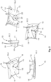
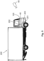
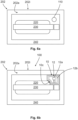
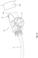
- the Figure 1 shows a door handle module 100 according to the invention before assembly into a ready-to-use module on a handle device 202 of a movable part 201 of a vehicle 200, preferably a commercial vehicle, which is shown below in the Figure 5 is shown schematically.
- the door handle module 100 is characterized in that it includes a housing 10 in which an electronics unit 12 is completely accommodated.
- the housing 10 can, for example, be in two parts with a first housing part 10.1 (see. Figure 3 ) and a second housing part 10.2 (see. Figure 2 ) be trained. There is one in the housing 10 Recording 11 designed to accommodate the electronics unit 12.
- the housing 10 can be in one piece and have an opening through which the electronics unit 12 can be inserted into the receptacle 11.
- the receptacle 11 can be relatively flat in order to accommodate the electronics unit 12 in the form of a circuit board (see Fig. Figures 1 , 2 and 7 ).
- two receiving pins 15 can be provided on the inside of the second housing part 10.2, which can engage in specially designed openings 15a on the circuit board of the electronic unit 12.
- the electronics unit 12 can be hot-sealed using the receiving pins 15 on the second housing part 10.2 in order to arrange the electronics unit 12 captively on the housing 10, possibly over some spacer elements 15b on the receiving pins 15 (production step a), which is based on Figure 7 is explained).
- the housing 10 according to the invention preferably forms a closed and sealed receptacle 11 for the electronics unit 12, in which the electronics unit 12 is reliably protected against weather and mechanical influences.
- an actuation section 19 can be provided, which can indicate the position of a wireless communication element 12b on the electronic unit 12, which is in the Figure 6b is indicated.
- the wireless communication element 12b is intended to improve the functions of the handle device 202 in order to enable wireless actuation of a security system 203 of the vehicle 200, for example to unlock a lock of the movable part 201 without a key (see Fig. Figure 5 ).
- the electronics unit 12 serves to provide a wireless communication capability for a vehicle-external communication unit 50 and the handle device 202 of the movable part 201 of the vehicle 200.
- the vehicle-external communication unit 50 can be designed, for example, in the form of an ID transmitter, a smartphone or the like.
- the electronics unit 12 can receive data, for example identification data, from the vehicle-external communication unit 50 and send it to the security system 203, e.g. B. in the form of an access control system.
- the electronics unit 12 can, for example via the security system 203 of the vehicle 200, trigger an actuation of a lock of the movable part 201 in order to unlock the movable part 201, whereby the movable part 201 for opening using the Handle device 202 will be released.
- the door handle module 100 according to the invention enables remote control of the security system 203 in the form of a keyless go or a keyless entry system. This allows the comfort when operating the security system 203 to be modernized.
- the door handle module 100 according to the invention can improve the safety when operating the security system 203.
- the electronic unit 12 can be used to store driving data, for example a logbook, user profiles or wear-related vehicle data, in order to expand the existing functions in the vehicle 200.
- driving data for example a logbook, user profiles or wear-related vehicle data
- connection element 40 in the form of a cable 41 with a first plug 42 for example in the form of a MolexO plug, is then led through a connection opening 16 in the second housing part 10.2 to the electronic unit 12 (production step b), which is based on the Figure 7 is explained) and connected to the electronic unit 12, in particular soldered (manufacturing step c), which is based on Figure 7 is explained).
- the two housing parts 10.1, 10.2 can be connected and, for example, hot-clamped by means of connecting openings 17 on the second housing part 10.2 and connecting pins 18 on the first housing part 10.1, as is the case Figure 8 indicates (manufacturing step d), which is based on the Figure 8 is explained). It is also conceivable that the connecting openings 17 and the connecting pins 18 can be designed as corresponding fastening elements, for example locking elements, in order to fasten the two housing parts 10.1, 10.2 to one another in a positive and/or non-positive manner. In addition, the housing parts 10.1, 10.2 can be glued to a connecting seam, for example on the edge.
- the receptacle 11 in the housing 10 can be filled with a casting compound (production step e), which is based on the Figure 9 is explained), for which two filler necks 14 can be provided on the back of the second housing part 10.2, which can also serve to center the door handle module 100 on the handle device 202, as shown in the view of Figure 10 is clarified.
- the assembled door handle module 100 is manufactured in the manufacturing steps a) to e), which will be discussed below with reference to Figures 7 to 10 is discussed in detail, as one, Preferably a completely closed and sealed retrofit part is provided, which can be easily, conveniently and without great assembly effort mounted on the handle device 202, which is exemplified in the Figures 6a and 6b is shown.
- the invention provides a relatively flat door handle module 100 so as not to interfere with the design and aerodynamic requirements of the handle device 202.
- the door handle module 100 according to the invention is fastened to the handle device 202 using a fastening adapter 30, which is in the Figures 4 and 10 is shown.
- the fastening adapter 30 can be inserted from the inside of the handle device 202 to attach the door handle module 100 to the handle device 202, as described below in the Figure 10 will be shown.
- a bayonet lock can be produced between the fastening adapter 30 and a connecting element 20 on a second housing part 10.2 of the door handle module 100.
- the fastening adapter 30 and the connecting element 20 can extend through a mounting receptacle 210, for example a lock cylinder receptacle, of the handle device 202, which is in the Figure 6a is shown.
- the fastening adapter 30 itself can be screwed to the inside of the handle device 202, as is the case Figure 10 shows.
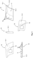
- the Figure 2 shows the second housing part 10.2 alone from different views, namely from top left to bottom right, first from an inside, then from a narrow side, from an outside, from a broad side and in a perspective view.
- the second housing part 10.2 has a substantially flat shape with a likewise flat receptacle 11, in which the electronics unit 12 is received in the form of a circuit board with an attached sensor element 12a and a communication means 12b.
- receiving pins 15 are provided, which can be received in corresponding openings 15a on the circuit board of the electronics unit 12 (production step a), which is in the Figure 7 is shown).
- the outer tips of the receiving pins 15 can be used to hot-stamp the electronics unit 12 on the second housing part 10.2, whereby the electronics unit 12 is securely fastened to the second housing part 10.2.
- the lower approaches of the receiving pins 15 can have rib-like, projecting spacer elements 15b in order to position the electronics unit 12 at a predetermined distance from the inside of the second housing part 10.2. This distance can be used to encapsulate the electronics unit 12 in manufacturing step e), which is based on the Figure 9 is explained.
- the spacer elements 15b ensure more stability of the finished door handle module 100.
- the second housing part 10.2 has a connection opening 16 for the connection element 40, which is designed to be complementary to the first plug 42 of the connection element 40 in order to accommodate the first plug 42, preferably without play.
- two outwardly projecting filler supports 14 are provided on the second housing part 10.2, which on the one hand are used to position or fix the door handle module 100 on the handle device 202 (see Fig. Figure 10 ) and on the other hand serve to fill the receptacle 11 with the casting compound (see manufacturing step e) in the Figure 9 ) can.
- the second housing part 10.2 has a plurality of connection openings 17 on an edge section, which can be used to connect to the connecting pins 18 of the first housing part 10.1, which alone in the Figure 3 is shown.
- An edge arrangement of the connecting openings 17 can serve to correctly position the two housing parts 10.1, 10.2 relative to one another when producing the door handle module 100.
- the second housing part 10.2 is formed with a connecting element 20, which can be formed monolithically and/or of the same material as the second housing part 10.2, for example cast in one piece.
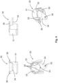
- the connecting element 20 has a substantially cylindrical guide body 21, which can be accommodated coaxially to and within a cylindrical guide section 31 of the fastening adapter 30 during assembly of the door handle module 100 on the handle device 202, as is the case Figure 10 shows.
- the fastening adapter 30 is described below in isolation Figure 4 shown.
- Cam or projection-like positioning means 23 are formed radially projecting from the cylindrical guide body 21 of the connecting element 20.
- the positioning means 23 can be inserted into groove-shaped receiving means 33 on the annular receiving element 32 inside of the cylindrical guide section 31 of the fastening adapter 30 intervene when the connecting element 20 is correctly aligned with the fastening adapter 30 in order to carry out a plugging movement of the fastening adapter 30.
- the fastening adapter 30 When pushed onto the cylindrical guide body 21 of the connecting element 20, the fastening adapter 30 can be rotated in order to prevent the plug connection to the connecting element 20 from becoming loose.
- the cam-like or projection-like positioning means 23 leave the groove-shaped receiving means 33 after the fastening adapter 30 has been inserted onto the connecting element 20 and move on the annular receiving element 32 after the fastening adapter 30 has been rotated relative to the connecting element 20.
- the Figure 3 shows the first housing part 10.1 in several views, which closes the receptacle 11 and is arranged on the handle device 202, visible to the outside.
- the first housing part 10.1 has a plurality of laterally arranged connecting pins 18 for connecting to the connecting openings 17 on the second housing part 10.2.
- the first housing part 10.1 has, for example, two laterally arranged undercuts 10.3, under which the second housing part 10.2 can first be pushed in in order to then be lowered onto the connecting pins 18, as is the case Figure 8 indicates.
- a plug-in pivoting movement of the two housing parts 10.1, 10.2 can be carried out relative to one another in order to close the receptacle 11. This movement is predetermined by the undercuts 10.3 and the connecting pins 18, so that the door handle module 100 can be assembled easily and even intuitively.
- An actuating section 19 can be depicted on the outside of the first housing part 10.1 in order to determine the position of the wireless communication means 12b on the electronics unit 12, which is in the Figure 6b is shown to indicate.
- the Figure 4 shows the mounting adapter 30 in several views.
- the fastening adapter 30 has a fastening arm 34 projecting radially from the cylindrical guide section 31 with a fastening means 35 in the form of an opening for a screw 35a in order to screw the fastening adapter 30 to an inside 202i of the handle device 202 (see. Figure 10 ).
- the fastening adapter 30 can be screwed together after the fastening adapter 30 has been pushed in between the opening of the mounting receptacle 210 on the handle device 202 and the outside of the connecting element 20 and twisted in such a way that it is no longer possible to pull out the fastening adapter 30.
- the fastening adapter 30 can have at least one strain relief element 36 in order to wind the cable 41 of the connecting element 40 thereon and absorb the tensile forces, as is the case, for example Figure 10 indicates.
- the Figure 5 shows a commercial vehicle as an example of a vehicle 200, which can be upgraded with the door handle module 100 according to the invention.
- the door handle module 100 according to the invention can be advantageous in order to enable keyless operation of the security system 203 of the vehicle 200 by means of the external communication unit 50 in order to control the movable part 201, for example Shaped like a door that can be unlocked remotely.
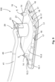
- the Figures 6a and 6b show an exemplary handle device 202 with an outside 202a, to which the housing 10 of the door handle module 100 according to the invention can be attached.
- the handle device 202 can have a handle recess 220 with a handle 330 arranged there, which is formed on an outer shell 240 of the handle device 202.
- the handle 330 can be a rigid or movable handle 330.
- the handle device 202 has a module receptacle 210 in the form of a lock cylinder receptacle, on which the door handle module 100 according to the invention is arranged.
- the module holder 210 is shown schematically below the outer shell 240 and above the handle 230 and the recessed grip 220.
- the door handle module 100 has a recess 10c in the area of the handle recess 220 in order to adapt the door handle module 100 to the outer contour of the handle recess 220 of the handle 230.
- the door handle module 100 completely closes the module receptacle 210 and extends essentially flush with the outer shell 240 of the Handle device 202.
- the housing 10 of the door handle module 100 can be colored or solid-colored in such a way that there is no difference in color to the outer shell 240, the handle 230 and the door handle recess 220.
- the electronics unit 12 can be arranged within the housing 10 of the door handle module 100.
- the electronic unit 12 can have a sensor element 12a as a communication element 12a, which can be designed as a proximity sensor, for example a capacitive sensor.
- the sensor element 12a can serve to detect a user approaching the door handle module 100 in order to wake up the electronics unit 12 for data communication with the vehicle-external communication unit 50, which is in the Figure 5 is shown as an example.
- the electronics unit 12 can have a wireless communication element 12b, which can be designed as an NFC communication element in order to ensure communication between the security system 203 of the vehicle 200 and the vehicle-external communication unit 50, which the user can carry with him.
- FIGS. 7 to 9 serve to illustrate steps a) to e) according to the invention for producing a door handle module 100, which can be designed as described above.
- Contacts 44 are provided for soldering the first plug 42 to the electronics unit 12.
- the electronics unit 12 is fastened in the receptacle 11 and is connected to the first plug 42 of the connection element 40, there remains space around the electronics unit 12 to be cast with a casting compound through the filling supports 14.
- the connection points between the first plug 42 and the contacts 44 on the electronics unit 12 are secured and sealed.
- the Figure 8 shows another step for producing the door handle module 100: d) Fastening the first housing part 10.1 of the housing 10 to the second housing part 10.2 of the housing 10 in order to provide the receptacle 11 for the electronics unit 12.
- the second housing part 10.2 can first be pushed under the undercuts 10.3 on the first housing part 10.1 and then lowered onto the connecting pins 18.
- the two housing parts 10.1, 10.2 can thus carry out a plug-in pivoting movement towards one another in order to close the receptacle 11.
- the arrangement of the undercuts 10.3 and the connecting pins 18 indicates a specific arrangement of the two housing parts 10.1, 10.2 relative to one another, in which they can be fastened to one another. This allows any assembly errors to be avoided.
- the Figure 9 indicates a further step for producing the door handle module 100: e) Filling the receptacle 11 with a casting compound in order to seal at least the electronics unit 12 or a first plug 42 of a connection element 40.
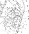
- the Figure 10 shows the door handle module 100 according to the invention in a mounted state on the handle device 202 in a view of an inside 202i of the handle device 202.
- the housing 10 of the door handle module 100 is fixed on the outside 202a of the handle device 202 (see Fig . the filling supports 14, which protrude through corresponding openings in the handle device 202) and are fastened to the handle device 202 by the fastening adapter 30 from the inside 202i of the handle device 202.
- the module receptacle 210, the connecting element 20 and the fastening adapter 30 extend coaxially to one another.
- the housing 10 of the door handle module 100 comes from the outside 202a of the handle device 202 and the fastening arm 34 of the fastening adapter 30 comes from the inside 202i Handle device 202 for support.
- the door handle module 100 is mounted reliably and securely on the handle device 202.
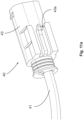
- the Figure 11a shows a connection element 40 with a second plug 43 at a security system-side end of the connection element 40.
- the second plug 43 can have a clip guide 43a in order to fix the connection element 40 on the vehicle 200, preferably in the vicinity of the security system 203.
- the Figure 11b shows a mounting clip 13 designed to complement the clip guide 43a, which can be provided in a set with the door handle module 100 according to the invention.
- the Figure 12 shows the clip guide 43a in engagement with the mounting clip 13.
- one or more guide clips 43b can be provided along the length of the cable 41 of the connection element 40, with an exemplary guide clip 43b in the Figure 10 is shown. Together with the second plug 43, the mounting clip 13 and the guide clips 43b, a complete kit can be provided with which the door handle module 100 is attached to the handle device 202 and the connecting element 40 is easily and conveniently laid on the vehicle 200 and guided up to the security system 203 can.
Landscapes
- Engineering & Computer Science (AREA)
- Mechanical Engineering (AREA)
- Computer Networks & Wireless Communication (AREA)
- Physics & Mathematics (AREA)
- General Physics & Mathematics (AREA)
- Manufacturing & Machinery (AREA)
- Chemical & Material Sciences (AREA)
- Combustion & Propulsion (AREA)
- Transportation (AREA)
- Lock And Its Accessories (AREA)
Claims (15)
- Module de poignée de porte (100) pour un dispositif de poignée (202) d'une partie mobile (201) d'un véhicule (200), en particulier d'un véhicule utilitaire :un boîtier (10) dans lequel est formé un logement (11),dans lequelle est disposée une unité électronique (12) pour commander un système de sécurité (203) du véhicule (200),dans lequel l'unité électronique (12) présente au moins un élément de communication (12a, 12b) pour échanger des données avec une unité de communication (50) externe au véhicule,caractérisé en ce quele module de poignée de porte (100) est conçu pour être monté sur un logement de module (210) du dispositif de poignée (202), qui est réalisé sous la forme d'un logement déjà existant sur le dispositif de poignée (202), d'un logement de cylindre de serrure ou d'un logement à fabriquer spécialement à cet effet sous la forme d'un alésage.
- Module de poignée de porte (100) selon la revendication précédente,
caractérisé en ce quel'unité électronique (12) présente au moins un élément de communication (12a, 12b) sous la forme d'un élément de détection (12a), en particulier d'un élément de détection capacitif, afin de réveiller l'unité électronique (12),et/ou en ce que l'unité électronique (12) présente au moins un élément de communication (12a, 12b) sous la forme d'un élément de communication sans fil (12b), en particulier un élément de communication NFC, Bluetooth, infrarouge, GSM, LTE, UMTS, mobile, HF, UHF, LF et/ou WLAN, pour assurer une communication du système de sécurité (203) du véhicule (200) et de l'unité de communication (50) externe au véhicule. - Module de poignée de porte (100) selon l'une quelconque des revendications précédentes, caractérisé en ce quele boîtier (10) est réalisé d'une seule pièce ou en deux parties avec une première partie de boîtier (10.1) qui sert au moins à recouvrir le logement (11) ou à le disposer de manière visible sur le dispositif de poignée (202), et avec une deuxième partie de boîtier (10.2) qui sert au moins à fixer l'unité électronique (12) ou à établir une liaison de l'élément de liaison (20) avec l'adaptateur de fixation (30),et/ou en ce que le boîtier (10) présente, en particulier sur une deuxième partie de boîtier (10.2), au moins une, de préférence deux, broche(s) de réception (15) pour fixer l'unité électronique (12) sur le boîtier (10), en particulier pour la sertir à chaud,et/ou en ce que le boîtier (10) présente, en particulier sur une deuxième partie de boîtier (10.2), une ouverture de raccordement (16) pour un élément de raccordement (40), de préférence pour un premier connecteur (42) de l'élément de raccordement (40) à raccorder à l'unité électronique (12),et/ou en ce que le boîtier (10), en particulier sur une deuxième partie de boîtier (10.2), présente au moins un, de préférence deux, appuis de remplissage (14) pour remplir au moins le logement (11) avec une masse de scellement ou pour positionner le boîtier (10) sur un côté extérieur (202a) du dispositif de poignée (202).
- Module de poignée de porte (100) selon l'une quelconque des revendications précédentes, caractérisé en ce quele boîtier (10), en particulier sur une deuxième partie de boîtier (10.2), présente au moins une, de préférence plusieurs, ouvertures de liaison (17) disposées de préférence d'un seul côté, qui coopèrent avec des broches de liaison (18) sur une première partie de boîtier (10.1) pour fixer la première partie de boîtier (10.1) sur la deuxième partie de boîtier (10.2), en particulier pour la bloquer à chaud,et/ou en ce que le boîtier (10), en particulier sur une première partie de boîtier (10.1), présente une section d'actionnement (19) pour indiquer l'au moins un élément de communication (12a, 12b) de l'unité électronique (12),et/ou en ce que le boîtier (10), en particulier sur une première partie de boîtier (10.1), présente au moins une, de préférence plusieurs, contre-dépouilles (10.3), de préférence disposées d'un seul côté, pour positionner la première partie de boîtier (10.1) sur la deuxième partie de boîtier (10.2).
- Module de poignée de porte (10) selon l'une quelconque des revendications précédentes, caractérisé en ce qu'il est prévu un élément de raccordement (40), en particulier sous la forme d'un câble (41) avec un premier connecteur (42), en particulier sous la forme d'un connecteur à enclenchement, pour le raccordement à l'unité électronique (12) et un deuxième connecteur (43) pour le raccordement au système de sécurité (203) du véhicule (200), et/ou en ce qu'un élément de raccordement (40), en particulier sur un deuxième connecteur (43), présente un guidage par clip (43a), afin de fixer l'élément de raccordement (40) sur le véhicule (200), de préférence sur un clip de montage (13) du véhicule (200) réalisé de manière complémentaire à celui-ci,et/ou en ce qu'il est prévu au moins un clip de guidage (43b) pour un élément de raccordement (40), en particulier pour un câble (41) de l'élément de raccordement (40), afin de positionner l'élément de raccordement (40), de préférence le câble (41) de l'élément de raccordement (40), sur le véhicule (200).
- Module de poignée de porte (100) selon la revendication précédente,
caractérisé en ce qu'un adaptateur de fixation (30), en particulier séparé, est prévu pour être inséré par un côté intérieur (202i) du dispositif de poignée (202),et/ou en ce qu'il est prévu sur le boîtier (10) un élément de liaison (20), réalisé en particulier dans le même matériau et/ou de manière monolithique avec le boîtier (10), pour l'insertion d'un côté extérieur (202a) du dispositif de poignée (202),et/ou en ce que le module de poignée de porte (100) peut être fixé sur le dispositif de poignée (202) par une liaison d'un élément de liaison (20) côté boîtier avec un adaptateur de fixation (30), de préférence séparé,dans lequel, en particulier, un adaptateur de fixation (30), de préférence séparé, est réalisé pour établir au moins une liaison par complémentarité de forme et/ou de force, une liaison par enfichage et rotation, une fermeture à baïonnette, une fermeture à vis ou une fermeture à encliquetage, avec un élément de liaison (20) côté boîtier,et/ou en ce qu'un adaptateur de fixation (30), de préférence séparé, présente une section de guidage (31), en particulier au moins partiellement cylindrique, qui peut être reçue dans un logement de module (210), de préférence dans un logement de cylindre de serrure, du dispositif de poignée (202),et/ou en ce qu'un adaptateur de fixation (30), de préférence séparé, est réalisé de manière géométriquement complémentaire à un logement de module (210), en particulier à un logement de cylindre de fermeture, du dispositif de poignée (202). - Module de poignée de porte (100) selon l'une quelconque des revendications précédentes, caractérisé en ce qu'un adaptateur de fixation (30), de préférence séparé, présente, en particulier à l'intérieur d'une section de guidage (31), un élément de réception (32), de préférence sensiblement annulaire, qui est conçu de manière à permettre une liaison d'un élément de liaison (20) côté boîtier avec l'adaptateur de fixation (30) dans seulement une orientation prédéfinie de l'élément de liaison (20) par rapport à l'adaptateur de fixation (30),et/ou en ce qu'un adaptateur de fixation (30), de préférence séparé, présente, en particulier sur un élément de réception (32), au moins un moyen de réception (33), de préférence en forme de rainure, pour un moyen de positionnement (23), de préférence en forme de came, sur un élément de liaison (20) côté boîtier.
- Module de poignée de porte (100) selon l'une quelconque des revendications précédentes, caractérisé en ce qu'un adaptateur de fixation (30), de préférence séparé, présente au moins un bras de fixation (34), dépassant en particulier du côté extérieur sur une section de guidage (31), afin de fixer l'adaptateur de fixation (30) sur le dispositif de poignée (202) par complémentarité de forme et/ou de force,et/ou en ce qu'un adaptateur de fixation (30), de préférence séparé, présente, en particulier sur un bras de fixation (34), un moyen de fixation (35), de préférence sous la forme d'une ouverture de réception pour une vis (35a) ou sous la forme d'un élément d'encliquetage pour un élément d'encliquetage opposé complémentaire du dispositif de poignée (202).
- Module de poignée de porte (100) selon l'une quelconque des revendications précédentes, caractérisé en ce qu'
un adaptateur de fixation (30), de préférence séparé, présente au moins un élément de décharge de traction (36), en particulier faisant saillie du côté extérieur sur un section de guidage (31), pour un élément de raccordement (40), en particulier pour un câble (41) de l'élément de raccordement (40). - Module de poignée de porte (100) selon l'une quelconque des revendications précédentes, caractérisé en ce qu'un élément de liaison (20) côté boîtier présente un corps de guidage (21), en particulier cylindrique au moins par sections, qui peut être reçu dans un adaptateur de fixation (30), en particulier à l'intérieur d'une section de guidage (31),et/ou en ce qu'un élément de liaison (20) côté boîtier est réalisé de manière géométriquement complémentaire à un adaptateur de fixation (30), de préférence séparé, et/ou en ce qu'un élément de liaison (20) côté boîtier présente, en particulier côté extérieur, au moins un moyen de positionnement (23), de préférence en forme de came, qui peut être amené en liaison active mécanique avec un élément de réception (32), en particulier avec un moyen de réception (33) en forme de rainure, sur un adaptateur de fixation (30), de préférence séparé, afin de permettre la liaison de l'élément de liaison (20) avec l'adaptateur de fixation (30) dans seulement une orientation prédéfinie de l'élément de liaison (20) par rapport à l'adaptateur de fixation (30).
- Procédé de montage d'un module de poignée de porte (100) sur un dispositif de poignée (202) d'une partie mobile (201) d'un véhicule (200), notamment d'un véhicule utilitaire (200), le module de poignée de porte (100) étant configuré pour échanger des données avec une unité de communication (50) externe au véhicule et pour commander un système de sécurité (203) du véhicule (200) selon l'une quelconque des revendications précédentes,
dans lequel un boîtier (10) du module de poignée de porte (100) est fixé sur un côté extérieur (202a) du dispositif de poignée (202) et est fixé au dispositif de poignée (202) par un adaptateur de fixation (30) depuis un côté intérieur (202i) du dispositif de poignée (202). - Procédé selon la revendication précédente,
caractérisé en ce que
le module de poignée de porte (100) est fixé au dispositif de poignée (202) par la réalisation d'une liaison par complémentarité de forme et/ou de force, en particulier d'une liaison par enfichage et rotation, de préférence d'une fermeture à baïonnette, d'une fermeture à vis ou d'une fermeture à encliquetage, d'un élément de liaison (20) du boîtier (10), réalisé en particulier dans le même matériau et/ou de manière monolithique avec le boîtier (10), avec l'adaptateur de fixation (30). - Procédé de fabrication d'un module de poignée de porte (100) pour un dispositif de poignée (202) d'une partie mobile (201) d'un véhicule (200), notamment d'un véhicule utilitaire (200), le module de poignée de porte (100) selon l'une des revendications précédentes étant configuré pour échanger des données avec une unité de communication (50) externe au véhicule et pour commander un système de sécurité (203) du véhicule (200),dans lequel un boîtier (10) est prévu pour le module de poignée de porte (100), dans lequel un logement (11) est formé avec une unité électronique (12) pour commander le système de sécurité (203) du véhicule (200),dans lequel l'unité électronique (12) présente au moins un élément de communication (12a, 12b) pour échanger des données avec une unité de communication (50) externe au véhicule.
- Procédé selon l'une quelconque des revendications précédentes,
caractérisé en ce quele procédé comprend au moins une des étapes suivantes :a) montage de l'unité électronique (12) sur une deuxième partie (10.2) du boîtier (10),b) l'insertion d'un premièr connecteur (42) d'un élément de raccordement (40) à travers un élément de liaison (20) sur une deuxième partie (10.2) du boîtier (10), ouc) le raccordement, en particulier le brasage, d'un premièr connecteur (42) d'un élément de raccordement (40) à l'unité électronique (12),et/ou en ce que le procédé comprend au moins une étape supplémentaire :
d) fixer une première partie de boîtier (10.1) du boîtier (10) à une deuxième partie de boîtier (10.2) du boîtier (10) afin de fournir le logement (11) pour l'unité électronique (12),et/ou en ce que le procédé comprend au moins une étape supplémentaire :
e) remplir le logement (11) avec une masse de scellement pour rendre étanche au moins l'unité électronique (12) ou un premier connecteur (42) d'un élément de raccordement (40). - Procédé de fourniture d'un module de poignée de porte (100) pour un dispositif de poignée (202) d'une partie mobile (201) d'un véhicule (200), notamment d'un véhicule utilitaire (200), le module de poignée de porte (100) étant configuré pour échanger des données avec une unité de communication (50) externe au véhicule et pour commander un système de sécurité (203) du véhicule (200) selon l'une quelconque des revendications précédentes,
le procédé comprenant au moins un procédé de fabrication du module de poignée de porte (100) selon l'une quelconque des revendications précédentes ou un procédé de montage du module de poignée de porte (100) sur le dispositif de poignée (202) selon l'une quelconque des revendications précédentes.
Applications Claiming Priority (1)
| Application Number | Priority Date | Filing Date | Title |
|---|---|---|---|
| DE102017117926.7A DE102017117926A1 (de) | 2017-08-07 | 2017-08-07 | Türgriffmodul |
Publications (2)
| Publication Number | Publication Date |
|---|---|
| EP3441266A1 EP3441266A1 (fr) | 2019-02-13 |
| EP3441266B1 true EP3441266B1 (fr) | 2023-10-11 |
Family
ID=63144892
Family Applications (1)
| Application Number | Title | Priority Date | Filing Date |
|---|---|---|---|
| EP18187266.4A Active EP3441266B1 (fr) | 2017-08-07 | 2018-08-03 | Module de poignée de porte |
Country Status (4)
| Country | Link |
|---|---|
| US (1) | US10753127B2 (fr) |
| EP (1) | EP3441266B1 (fr) |
| CN (1) | CN109386192A (fr) |
| DE (1) | DE102017117926A1 (fr) |
Families Citing this family (7)
| Publication number | Priority date | Publication date | Assignee | Title |
|---|---|---|---|---|
| DE102016110345A1 (de) * | 2016-06-03 | 2017-12-07 | Huf Hülsbeck & Fürst Gmbh & Co. Kg | Zusätzliches Türgriffmodul für eine Türgriffeinheit |
| US11091094B2 (en) * | 2018-05-15 | 2021-08-17 | Glory Creative, Inc. | Capacitive sensing car-door pre-opening warning device based on a flexible printed circuit |
| PL3715182T3 (pl) | 2019-03-28 | 2022-04-19 | Hella Gutmann Solutions GmbH | Adapter |
| DE102019124217A1 (de) * | 2019-06-11 | 2020-12-17 | Huf Hülsbeck & Fürst Gmbh & Co. Kg | Anordnung |
| DE102020213055A1 (de) | 2020-10-15 | 2022-04-21 | Volkswagen Aktiengesellschaft | Entriegelungssystem für eine Fahrzeugtür mit Drehverbindung |
| US11745676B2 (en) * | 2022-01-10 | 2023-09-05 | Kiekert Ag | Motor vehicle locking device |
| DE102022111437A1 (de) | 2022-05-09 | 2023-11-09 | Rehau Automotive Se & Co. Kg | Verfahren zur fehlerfreien Montage eines elektronischen Bauteils |
Family Cites Families (19)
| Publication number | Priority date | Publication date | Assignee | Title |
|---|---|---|---|---|
| JPS6261856A (ja) * | 1985-09-12 | 1987-03-18 | Yazaki Corp | 自動車の機能組込型配線装置 |
| DE59811066D1 (de) * | 1997-10-14 | 2004-04-29 | Huf Huelsbeck & Fuerst Gmbh | Schliessvorrichtung, insbesondere für kraftfahrzeuge |
| JP3648396B2 (ja) * | 1998-12-02 | 2005-05-18 | トヨタ自動車株式会社 | 車両用のドアハンドル |
| JP2000313288A (ja) * | 1999-04-30 | 2000-11-14 | Yazaki Corp | 車両用ワイヤハーネスの回路接続構造 |
| DE19943989C1 (de) * | 1999-09-14 | 2001-04-05 | Kostal Leopold Gmbh & Co Kg | Montagemodul |
| TWI236599B (en) * | 2000-06-02 | 2005-07-21 | Yamaha Corp | Multimedia system with synchronization of music and image tracks |
| JP3566943B2 (ja) * | 2001-07-02 | 2004-09-15 | アイシン精機株式会社 | 車両用ドアハンドル |
| JP4342207B2 (ja) * | 2003-04-22 | 2009-10-14 | アイシン精機株式会社 | 車両用ドアハンドル装置 |
| DE10348719A1 (de) * | 2003-10-16 | 2005-05-12 | Huf Huelsbeck & Fuerst Gmbh | Türaußengriff, insbesondere für Fahrzeuge |
| DE102004038569B3 (de) * | 2004-08-06 | 2005-10-20 | Huf Huelsbeck & Fuerst Gmbh | Kraftfahrzeugtürgriff |
| DE602007000993D1 (de) * | 2006-03-16 | 2009-06-10 | Aisin Seiki | Türgriffvorrichtung für Fahrzeuge |
| DE102006025075A1 (de) * | 2006-05-30 | 2007-12-06 | Hella Kgaa Hueck & Co. | Kapazitive Sensoreinrichtung |
| WO2008137634A1 (fr) * | 2007-05-03 | 2008-11-13 | Donnelly Corporation | Module d'éclairage pour un véhicule |
| DE102008054526A1 (de) * | 2008-12-11 | 2010-06-17 | Huf Hülsbeck & Fürst Gmbh & Co. Kg | Türgriffanordnung für ein Kraftfahrzeug |
| JP5556620B2 (ja) * | 2010-11-26 | 2014-07-23 | アイシン精機株式会社 | ドアハンドル装置 |
| CN205015482U (zh) * | 2015-07-21 | 2016-02-03 | 武汉中瀚科技有限公司 | 一种车载定位装置 |
| DE102016110345A1 (de) * | 2016-06-03 | 2017-12-07 | Huf Hülsbeck & Fürst Gmbh & Co. Kg | Zusätzliches Türgriffmodul für eine Türgriffeinheit |
| EP3566306A1 (fr) * | 2016-11-22 | 2019-11-13 | Huf Hülsbeck & Fürst GmbH & Co. KG | Poignée de porte avec système de capteurs |
| DE102017110145A1 (de) * | 2017-04-28 | 2018-10-31 | Huf Hülsbeck & Fürst Gmbh & Co. Kg | Fahrzeugtürgriff mit Antennenanordnung |
-
2017
- 2017-08-07 DE DE102017117926.7A patent/DE102017117926A1/de not_active Withdrawn
-
2018
- 2018-08-01 CN CN201810864415.1A patent/CN109386192A/zh active Pending
- 2018-08-03 EP EP18187266.4A patent/EP3441266B1/fr active Active
- 2018-08-07 US US16/056,572 patent/US10753127B2/en not_active Expired - Fee Related
Also Published As
| Publication number | Publication date |
|---|---|
| EP3441266A1 (fr) | 2019-02-13 |
| US20190040660A1 (en) | 2019-02-07 |
| DE102017117926A1 (de) | 2019-02-07 |
| CN109386192A (zh) | 2019-02-26 |
| US10753127B2 (en) | 2020-08-25 |
Similar Documents
| Publication | Publication Date | Title |
|---|---|---|
| EP3441266B1 (fr) | Module de poignée de porte | |
| EP2668062B1 (fr) | Dispositif de verrouillage, notamment pour un connecteur | |
| EP2212502B1 (fr) | Mécanisme d'entraînement pour porte avec unité d'entraînement | |
| EP3111029B1 (fr) | Système de poignée de porte pour véhicules | |
| DE102015209851A1 (de) | Kraftfahrzeug-Tür sowie Türgriffsystem für eine derartige Kraftfahrzeug-Tür | |
| EP3630555B1 (fr) | Dispositif formant contenant servant à stocker un transmetteur d'identifiant, insert servant à stocker un transmetteur d'identifiant, ainsi que procédé servant à actionner un transmetteur d'identifiant | |
| DE4008834C1 (en) | Interrogator for car door lock - has switch trip coupled to cylinder and connected to adjacent control switch | |
| DE102012100428A1 (de) | Türgriff für ein Kraftfahrzeug | |
| WO2017001130A1 (fr) | Système de poignée de porte pour véhicules | |
| EP1766165A1 (fr) | Procede permettant d'actionner une serrure incorporee dans une porte, un hayon ou analogue, en particulier dans un vehicule a moteur | |
| DE10060447B4 (de) | Innenspiegelanordnung | |
| WO2017207296A1 (fr) | Module de poignée de porte additionnel pour un ensemble poignée de porte | |
| EP2318225B1 (fr) | Agencement de portiere et procede de montage pour un agencement de portiere | |
| EP2998485B1 (fr) | Bouton rotatif destine a actionner un adaptateur de cylindre d'un barillet | |
| EP3845727B1 (fr) | Poignée de porte pour un véhicule | |
| DE10037760A1 (de) | Rückstelleinrichtung für einen Schalter eines Kraftfahrzeuges | |
| WO2017220259A1 (fr) | Poignée pour un élément mobile d'un véhicule automobile | |
| EP3044040B1 (fr) | Support de composants | |
| DE19961370A1 (de) | Türaußengriffanordnung für eine Kraftfahrzeugtür, Kraftfahrzeugtür und Verfahren zur Montage eines Türaußengriffs | |
| DE102015111937A1 (de) | Drehknauf zum Betätigen eines Zylinderadapters eines Schließzylinders | |
| DE19842225A1 (de) | Lenkstockmodul | |
| DE10110303A1 (de) | Verschließbarer Flügel für ein Kraftfahrzeug | |
| EP2998465B1 (fr) | Armature pour une porte de bâtiment et procédé associé | |
| DE102012101338A1 (de) | Wischerblatt-Montagewinkel, Verfahren zur Fertigung desselben und Wischerblatt-Montagewinkel-Baugruppe | |
| EP2998482A1 (fr) | Bouton rotatif destiné à actionner un adaptateur de cylindre d'un barillet |
Legal Events
| Date | Code | Title | Description |
|---|---|---|---|
| PUAI | Public reference made under article 153(3) epc to a published international application that has entered the european phase |
Free format text: ORIGINAL CODE: 0009012 |
|
| STAA | Information on the status of an ep patent application or granted ep patent |
Free format text: STATUS: THE APPLICATION HAS BEEN PUBLISHED |
|
| AK | Designated contracting states |
Kind code of ref document: A1 Designated state(s): AL AT BE BG CH CY CZ DE DK EE ES FI FR GB GR HR HU IE IS IT LI LT LU LV MC MK MT NL NO PL PT RO RS SE SI SK SM TR |
|
| AX | Request for extension of the european patent |
Extension state: BA ME |
|
| STAA | Information on the status of an ep patent application or granted ep patent |
Free format text: STATUS: REQUEST FOR EXAMINATION WAS MADE |
|
| 17P | Request for examination filed |
Effective date: 20190813 |
|
| RBV | Designated contracting states (corrected) |
Designated state(s): AL AT BE BG CH CY CZ DE DK EE ES FI FR GB GR HR HU IE IS IT LI LT LU LV MC MK MT NL NO PL PT RO RS SE SI SK SM TR |
|
| STAA | Information on the status of an ep patent application or granted ep patent |
Free format text: STATUS: EXAMINATION IS IN PROGRESS |
|
| 17Q | First examination report despatched |
Effective date: 20211014 |
|
| GRAP | Despatch of communication of intention to grant a patent |
Free format text: ORIGINAL CODE: EPIDOSNIGR1 |
|
| STAA | Information on the status of an ep patent application or granted ep patent |
Free format text: STATUS: GRANT OF PATENT IS INTENDED |
|
| INTG | Intention to grant announced |
Effective date: 20230320 |
|
| GRAS | Grant fee paid |
Free format text: ORIGINAL CODE: EPIDOSNIGR3 |
|
| GRAA | (expected) grant |
Free format text: ORIGINAL CODE: 0009210 |
|
| STAA | Information on the status of an ep patent application or granted ep patent |
Free format text: STATUS: THE PATENT HAS BEEN GRANTED |
|
| AK | Designated contracting states |
Kind code of ref document: B1 Designated state(s): AL AT BE BG CH CY CZ DE DK EE ES FI FR GB GR HR HU IE IS IT LI LT LU LV MC MK MT NL NO PL PT RO RS SE SI SK SM TR |
|
| REG | Reference to a national code |
Ref country code: GB Ref legal event code: FG4D Free format text: NOT ENGLISH |
|
| REG | Reference to a national code |
Ref country code: CH Ref legal event code: EP |
|
| REG | Reference to a national code |
Ref country code: DE Ref legal event code: R096 Ref document number: 502018013420 Country of ref document: DE |
|
| REG | Reference to a national code |
Ref country code: IE Ref legal event code: FG4D Free format text: LANGUAGE OF EP DOCUMENT: GERMAN |
|
| REG | Reference to a national code |
Ref country code: LT Ref legal event code: MG9D |
|
| REG | Reference to a national code |
Ref country code: NL Ref legal event code: MP Effective date: 20231011 |
|
| P01 | Opt-out of the competence of the unified patent court (upc) registered |
Effective date: 20240126 |
|
| PG25 | Lapsed in a contracting state [announced via postgrant information from national office to epo] |
Ref country code: NL Free format text: LAPSE BECAUSE OF FAILURE TO SUBMIT A TRANSLATION OF THE DESCRIPTION OR TO PAY THE FEE WITHIN THE PRESCRIBED TIME-LIMIT Effective date: 20231011 |
|
| PG25 | Lapsed in a contracting state [announced via postgrant information from national office to epo] |
Ref country code: GR Free format text: LAPSE BECAUSE OF FAILURE TO SUBMIT A TRANSLATION OF THE DESCRIPTION OR TO PAY THE FEE WITHIN THE PRESCRIBED TIME-LIMIT Effective date: 20240112 |
|
| PG25 | Lapsed in a contracting state [announced via postgrant information from national office to epo] |
Ref country code: IS Free format text: LAPSE BECAUSE OF FAILURE TO SUBMIT A TRANSLATION OF THE DESCRIPTION OR TO PAY THE FEE WITHIN THE PRESCRIBED TIME-LIMIT Effective date: 20240211 |
|
| PG25 | Lapsed in a contracting state [announced via postgrant information from national office to epo] |
Ref country code: LT Free format text: LAPSE BECAUSE OF FAILURE TO SUBMIT A TRANSLATION OF THE DESCRIPTION OR TO PAY THE FEE WITHIN THE PRESCRIBED TIME-LIMIT Effective date: 20231011 |
|
| PG25 | Lapsed in a contracting state [announced via postgrant information from national office to epo] |
Ref country code: ES Free format text: LAPSE BECAUSE OF FAILURE TO SUBMIT A TRANSLATION OF THE DESCRIPTION OR TO PAY THE FEE WITHIN THE PRESCRIBED TIME-LIMIT Effective date: 20231011 |
|
| PG25 | Lapsed in a contracting state [announced via postgrant information from national office to epo] |
Ref country code: LT Free format text: LAPSE BECAUSE OF FAILURE TO SUBMIT A TRANSLATION OF THE DESCRIPTION OR TO PAY THE FEE WITHIN THE PRESCRIBED TIME-LIMIT Effective date: 20231011 Ref country code: IS Free format text: LAPSE BECAUSE OF FAILURE TO SUBMIT A TRANSLATION OF THE DESCRIPTION OR TO PAY THE FEE WITHIN THE PRESCRIBED TIME-LIMIT Effective date: 20240211 Ref country code: GR Free format text: LAPSE BECAUSE OF FAILURE TO SUBMIT A TRANSLATION OF THE DESCRIPTION OR TO PAY THE FEE WITHIN THE PRESCRIBED TIME-LIMIT Effective date: 20240112 Ref country code: ES Free format text: LAPSE BECAUSE OF FAILURE TO SUBMIT A TRANSLATION OF THE DESCRIPTION OR TO PAY THE FEE WITHIN THE PRESCRIBED TIME-LIMIT Effective date: 20231011 Ref country code: BG Free format text: LAPSE BECAUSE OF FAILURE TO SUBMIT A TRANSLATION OF THE DESCRIPTION OR TO PAY THE FEE WITHIN THE PRESCRIBED TIME-LIMIT Effective date: 20240111 Ref country code: PT Free format text: LAPSE BECAUSE OF FAILURE TO SUBMIT A TRANSLATION OF THE DESCRIPTION OR TO PAY THE FEE WITHIN THE PRESCRIBED TIME-LIMIT Effective date: 20240212 |
|
| PG25 | Lapsed in a contracting state [announced via postgrant information from national office to epo] |
Ref country code: SE Free format text: LAPSE BECAUSE OF FAILURE TO SUBMIT A TRANSLATION OF THE DESCRIPTION OR TO PAY THE FEE WITHIN THE PRESCRIBED TIME-LIMIT Effective date: 20231011 Ref country code: RS Free format text: LAPSE BECAUSE OF FAILURE TO SUBMIT A TRANSLATION OF THE DESCRIPTION OR TO PAY THE FEE WITHIN THE PRESCRIBED TIME-LIMIT Effective date: 20231011 Ref country code: PL Free format text: LAPSE BECAUSE OF FAILURE TO SUBMIT A TRANSLATION OF THE DESCRIPTION OR TO PAY THE FEE WITHIN THE PRESCRIBED TIME-LIMIT Effective date: 20231011 Ref country code: NO Free format text: LAPSE BECAUSE OF FAILURE TO SUBMIT A TRANSLATION OF THE DESCRIPTION OR TO PAY THE FEE WITHIN THE PRESCRIBED TIME-LIMIT Effective date: 20240111 Ref country code: LV Free format text: LAPSE BECAUSE OF FAILURE TO SUBMIT A TRANSLATION OF THE DESCRIPTION OR TO PAY THE FEE WITHIN THE PRESCRIBED TIME-LIMIT Effective date: 20231011 Ref country code: HR Free format text: LAPSE BECAUSE OF FAILURE TO SUBMIT A TRANSLATION OF THE DESCRIPTION OR TO PAY THE FEE WITHIN THE PRESCRIBED TIME-LIMIT Effective date: 20231011 |
|
| PG25 | Lapsed in a contracting state [announced via postgrant information from national office to epo] |
Ref country code: DK Free format text: LAPSE BECAUSE OF FAILURE TO SUBMIT A TRANSLATION OF THE DESCRIPTION OR TO PAY THE FEE WITHIN THE PRESCRIBED TIME-LIMIT Effective date: 20231011 |
|
| REG | Reference to a national code |
Ref country code: DE Ref legal event code: R097 Ref document number: 502018013420 Country of ref document: DE |
|
| PG25 | Lapsed in a contracting state [announced via postgrant information from national office to epo] |
Ref country code: CZ Free format text: LAPSE BECAUSE OF FAILURE TO SUBMIT A TRANSLATION OF THE DESCRIPTION OR TO PAY THE FEE WITHIN THE PRESCRIBED TIME-LIMIT Effective date: 20231011 |
|
| PG25 | Lapsed in a contracting state [announced via postgrant information from national office to epo] |
Ref country code: SK Free format text: LAPSE BECAUSE OF FAILURE TO SUBMIT A TRANSLATION OF THE DESCRIPTION OR TO PAY THE FEE WITHIN THE PRESCRIBED TIME-LIMIT Effective date: 20231011 |
|
| PG25 | Lapsed in a contracting state [announced via postgrant information from national office to epo] |
Ref country code: SM Free format text: LAPSE BECAUSE OF FAILURE TO SUBMIT A TRANSLATION OF THE DESCRIPTION OR TO PAY THE FEE WITHIN THE PRESCRIBED TIME-LIMIT Effective date: 20231011 Ref country code: SK Free format text: LAPSE BECAUSE OF FAILURE TO SUBMIT A TRANSLATION OF THE DESCRIPTION OR TO PAY THE FEE WITHIN THE PRESCRIBED TIME-LIMIT Effective date: 20231011 Ref country code: RO Free format text: LAPSE BECAUSE OF FAILURE TO SUBMIT A TRANSLATION OF THE DESCRIPTION OR TO PAY THE FEE WITHIN THE PRESCRIBED TIME-LIMIT Effective date: 20231011 Ref country code: IT Free format text: LAPSE BECAUSE OF FAILURE TO SUBMIT A TRANSLATION OF THE DESCRIPTION OR TO PAY THE FEE WITHIN THE PRESCRIBED TIME-LIMIT Effective date: 20231011 Ref country code: EE Free format text: LAPSE BECAUSE OF FAILURE TO SUBMIT A TRANSLATION OF THE DESCRIPTION OR TO PAY THE FEE WITHIN THE PRESCRIBED TIME-LIMIT Effective date: 20231011 Ref country code: DK Free format text: LAPSE BECAUSE OF FAILURE TO SUBMIT A TRANSLATION OF THE DESCRIPTION OR TO PAY THE FEE WITHIN THE PRESCRIBED TIME-LIMIT Effective date: 20231011 Ref country code: CZ Free format text: LAPSE BECAUSE OF FAILURE TO SUBMIT A TRANSLATION OF THE DESCRIPTION OR TO PAY THE FEE WITHIN THE PRESCRIBED TIME-LIMIT Effective date: 20231011 |
|
| PLBE | No opposition filed within time limit |
Free format text: ORIGINAL CODE: 0009261 |
|
| STAA | Information on the status of an ep patent application or granted ep patent |
Free format text: STATUS: NO OPPOSITION FILED WITHIN TIME LIMIT |
|
| 26N | No opposition filed |
Effective date: 20240712 |
|
| PG25 | Lapsed in a contracting state [announced via postgrant information from national office to epo] |
Ref country code: SI Free format text: LAPSE BECAUSE OF FAILURE TO SUBMIT A TRANSLATION OF THE DESCRIPTION OR TO PAY THE FEE WITHIN THE PRESCRIBED TIME-LIMIT Effective date: 20231011 |
|
| PG25 | Lapsed in a contracting state [announced via postgrant information from national office to epo] |
Ref country code: SI Free format text: LAPSE BECAUSE OF FAILURE TO SUBMIT A TRANSLATION OF THE DESCRIPTION OR TO PAY THE FEE WITHIN THE PRESCRIBED TIME-LIMIT Effective date: 20231011 |
|
| REG | Reference to a national code |
Ref country code: CH Ref legal event code: PL |
|
| PG25 | Lapsed in a contracting state [announced via postgrant information from national office to epo] |
Ref country code: LU Free format text: LAPSE BECAUSE OF NON-PAYMENT OF DUE FEES Effective date: 20240803 |
|
| PG25 | Lapsed in a contracting state [announced via postgrant information from national office to epo] |
Ref country code: MC Free format text: LAPSE BECAUSE OF FAILURE TO SUBMIT A TRANSLATION OF THE DESCRIPTION OR TO PAY THE FEE WITHIN THE PRESCRIBED TIME-LIMIT Effective date: 20231011 Ref country code: CH Free format text: LAPSE BECAUSE OF NON-PAYMENT OF DUE FEES Effective date: 20240831 |
|
| REG | Reference to a national code |
Ref country code: BE Ref legal event code: MM Effective date: 20240831 |
|
| PG25 | Lapsed in a contracting state [announced via postgrant information from national office to epo] |
Ref country code: BE Free format text: LAPSE BECAUSE OF NON-PAYMENT OF DUE FEES Effective date: 20240831 |
|
| PG25 | Lapsed in a contracting state [announced via postgrant information from national office to epo] |
Ref country code: IE Free format text: LAPSE BECAUSE OF NON-PAYMENT OF DUE FEES Effective date: 20240803 |
|
| PG25 | Lapsed in a contracting state [announced via postgrant information from national office to epo] |
Ref country code: FI Free format text: LAPSE BECAUSE OF FAILURE TO SUBMIT A TRANSLATION OF THE DESCRIPTION OR TO PAY THE FEE WITHIN THE PRESCRIBED TIME-LIMIT Effective date: 20231011 |
|
| PGFP | Annual fee paid to national office [announced via postgrant information from national office to epo] |
Ref country code: DE Payment date: 20250831 Year of fee payment: 8 |
|
| REG | Reference to a national code |
Ref country code: AT Ref legal event code: MM01 Ref document number: 1619920 Country of ref document: AT Kind code of ref document: T Effective date: 20240803 |
|
| PGFP | Annual fee paid to national office [announced via postgrant information from national office to epo] |
Ref country code: GB Payment date: 20250818 Year of fee payment: 8 |
|
| PG25 | Lapsed in a contracting state [announced via postgrant information from national office to epo] |
Ref country code: AT Free format text: LAPSE BECAUSE OF NON-PAYMENT OF DUE FEES Effective date: 20240803 |
|
| PGFP | Annual fee paid to national office [announced via postgrant information from national office to epo] |
Ref country code: FR Payment date: 20250827 Year of fee payment: 8 |
|
| PG25 | Lapsed in a contracting state [announced via postgrant information from national office to epo] |
Ref country code: CY Free format text: LAPSE BECAUSE OF FAILURE TO SUBMIT A TRANSLATION OF THE DESCRIPTION OR TO PAY THE FEE WITHIN THE PRESCRIBED TIME-LIMIT; INVALID AB INITIO Effective date: 20180803 |
|
| PG25 | Lapsed in a contracting state [announced via postgrant information from national office to epo] |
Ref country code: HU Free format text: LAPSE BECAUSE OF FAILURE TO SUBMIT A TRANSLATION OF THE DESCRIPTION OR TO PAY THE FEE WITHIN THE PRESCRIBED TIME-LIMIT; INVALID AB INITIO Effective date: 20180803 |