EP3441266B1 - Door handle module - Google Patents
Door handle module Download PDFInfo
- Publication number
- EP3441266B1 EP3441266B1 EP18187266.4A EP18187266A EP3441266B1 EP 3441266 B1 EP3441266 B1 EP 3441266B1 EP 18187266 A EP18187266 A EP 18187266A EP 3441266 B1 EP3441266 B1 EP 3441266B1
- Authority
- EP
- European Patent Office
- Prior art keywords
- housing
- door handle
- vehicle
- handle module
- handle device
- Prior art date
- Legal status (The legal status is an assumption and is not a legal conclusion. Google has not performed a legal analysis and makes no representation as to the accuracy of the status listed.)
- Active
Links
Images


Classifications
-
- E—FIXED CONSTRUCTIONS
- E05—LOCKS; KEYS; WINDOW OR DOOR FITTINGS; SAFES
- E05B—LOCKS; ACCESSORIES THEREFOR; HANDCUFFS
- E05B81/00—Power-actuated vehicle locks
- E05B81/54—Electrical circuits
- E05B81/64—Monitoring or sensing, e.g. by using switches or sensors
- E05B81/76—Detection of handle operation; Detection of a user approaching a handle; Electrical switching actions performed by door handles
- E05B81/78—Detection of handle operation; Detection of a user approaching a handle; Electrical switching actions performed by door handles as part of a hands-free locking or unlocking operation
-
- B—PERFORMING OPERATIONS; TRANSPORTING
- B60—VEHICLES IN GENERAL
- B60R—VEHICLES, VEHICLE FITTINGS, OR VEHICLE PARTS, NOT OTHERWISE PROVIDED FOR
- B60R25/00—Fittings or systems for preventing or indicating unauthorised use or theft of vehicles
- B60R25/01—Fittings or systems for preventing or indicating unauthorised use or theft of vehicles operating on vehicle systems or fittings, e.g. on doors, seats or windscreens
-
- E—FIXED CONSTRUCTIONS
- E05—LOCKS; KEYS; WINDOW OR DOOR FITTINGS; SAFES
- E05B—LOCKS; ACCESSORIES THEREFOR; HANDCUFFS
- E05B85/00—Details of vehicle locks not provided for in groups E05B77/00 - E05B83/00
- E05B85/10—Handles
-
- B—PERFORMING OPERATIONS; TRANSPORTING
- B60—VEHICLES IN GENERAL
- B60J—WINDOWS, WINDSCREENS, NON-FIXED ROOFS, DOORS, OR SIMILAR DEVICES FOR VEHICLES; REMOVABLE EXTERNAL PROTECTIVE COVERINGS SPECIALLY ADAPTED FOR VEHICLES
- B60J5/00—Doors
-
- B—PERFORMING OPERATIONS; TRANSPORTING
- B60—VEHICLES IN GENERAL
- B60R—VEHICLES, VEHICLE FITTINGS, OR VEHICLE PARTS, NOT OTHERWISE PROVIDED FOR
- B60R16/00—Electric or fluid circuits specially adapted for vehicles and not otherwise provided for; Arrangement of elements of electric or fluid circuits specially adapted for vehicles and not otherwise provided for
- B60R16/02—Electric or fluid circuits specially adapted for vehicles and not otherwise provided for; Arrangement of elements of electric or fluid circuits specially adapted for vehicles and not otherwise provided for electric constitutive elements
- B60R16/023—Electric or fluid circuits specially adapted for vehicles and not otherwise provided for; Arrangement of elements of electric or fluid circuits specially adapted for vehicles and not otherwise provided for electric constitutive elements for transmission of signals between vehicle parts or subsystems
-
- B—PERFORMING OPERATIONS; TRANSPORTING
- B62—LAND VEHICLES FOR TRAVELLING OTHERWISE THAN ON RAILS
- B62D—MOTOR VEHICLES; TRAILERS
- B62D65/00—Designing, manufacturing, e.g. assembling, facilitating disassembly, or structurally modifying motor vehicles or trailers, not otherwise provided for
- B62D65/02—Joining sub-units or components to, or positioning sub-units or components with respect to, body shell or other sub-units or components
- B62D65/14—Joining sub-units or components to, or positioning sub-units or components with respect to, body shell or other sub-units or components the sub-units or components being passenger compartment fittings, e.g. seats, linings, trim, instrument panels
-
- E—FIXED CONSTRUCTIONS
- E05—LOCKS; KEYS; WINDOW OR DOOR FITTINGS; SAFES
- E05B—LOCKS; ACCESSORIES THEREFOR; HANDCUFFS
- E05B81/00—Power-actuated vehicle locks
- E05B81/54—Electrical circuits
- E05B81/64—Monitoring or sensing, e.g. by using switches or sensors
- E05B81/76—Detection of handle operation; Detection of a user approaching a handle; Electrical switching actions performed by door handles
-
- G—PHYSICS
- G07—CHECKING-DEVICES
- G07C—TIME OR ATTENDANCE REGISTERS; REGISTERING OR INDICATING THE WORKING OF MACHINES; GENERATING RANDOM NUMBERS; VOTING OR LOTTERY APPARATUS; ARRANGEMENTS, SYSTEMS OR APPARATUS FOR CHECKING NOT PROVIDED FOR ELSEWHERE
- G07C9/00—Individual registration on entry or exit
- G07C9/00174—Electronically operated locks; Circuits therefor; Nonmechanical keys therefor, e.g. passive or active electrical keys or other data carriers without mechanical keys
- G07C9/00309—Electronically operated locks; Circuits therefor; Nonmechanical keys therefor, e.g. passive or active electrical keys or other data carriers without mechanical keys operated with bidirectional data transmission between data carrier and locks
-
- E—FIXED CONSTRUCTIONS
- E05—LOCKS; KEYS; WINDOW OR DOOR FITTINGS; SAFES
- E05B—LOCKS; ACCESSORIES THEREFOR; HANDCUFFS
- E05B79/00—Mounting or connecting vehicle locks or parts thereof
- E05B79/02—Mounting of vehicle locks or parts thereof
- E05B79/06—Mounting of handles, e.g. to the wing or to the lock
Definitions
- the present invention relates to a door handle module for a handle device of a movable part, such as. B. a door or a flap, a vehicle, in particular a commercial vehicle, according to the independent device claim, a method for mounting a door handle module on a handle device according to the corresponding independent method claim, a method for producing a door handle module for a handle device according to the corresponding independent method claim and a method for providing a door handle module for a handle device according to the corresponding independent method claim.
- Handle devices for vehicles can sometimes have a long series production time, so that corresponding models of the handle devices are used over a long period of time, especially on commercial vehicles.
- functionalities of modern handle devices for example due to a lack of electronic functions, as the product life cycle is correspondingly extended in vehicles with a long period of use and the range of functions of handle devices that have already been installed is limited.
- Upgrading electronic units on conventional handle devices involves considerable assembly effort and a comprehensive modification of the handle devices.
- replica electronic units are exposed to the effects of the weather and can therefore malfunction.
- the object of the present invention is to provide an expanded range of functions for existing handle devices on vehicles, in particular commercial vehicles, and preferably to subsequently improve the comfort and / or safety of security systems, in particular access control systems of the vehicles.
- a door handle module with the features of the first independent device claim a method for mounting a door handle module on a handle device with the features of the corresponding independent method claim, a method for producing a door handle module for a handle device with the features of the corresponding independent method claim and a method for providing a door handle module for a handle device with the features of the corresponding independent method claim.
- the invention provides a door handle module for a handle device of a movable part, such as. B. a door or flap, a vehicle, in particular a commercial vehicle, ready, comprising: a housing in which a, in particular closed, preferably sealed, receptacle is formed, in which an electronic unit for controlling a security system of the vehicle is arranged, the Electronic unit has at least one communication element for exchanging data with a vehicle-external communication unit.
- the electronic unit serves to provide wireless communication capability with a vehicle-external communication unit on the handle device of the movable part of the vehicle.
- a vehicle-external communication unit such as B. a mobile device, laptop and / or ID transmitter
- the electronic unit can receive data, for example identification data, which the electronic unit, for example for checking, to the security system, e.g. B. in the form of an access control system.
- the data can be forwarded from the electronic unit to the security system via a cable.
- the electronic unit can, for example via the vehicle's security system, cause a lock of the movable part to be actuated in order to unlock the movable part, whereby the movable part is released for opening by means of the handle device.
- the door handle module according to the invention can thus enable remote control of the security system. This allows the comfort when operating the security system to be adapted to modern requirements and thus improved. For example, B. the driver of the vehicle subsequently (meaning through the conversion) through the use of the invention will be able to open and, if necessary, start the vehicle (in particular exclusively) with their mobile device.
- the driver is sent wirelessly corresponding access data (e.g. from a shipping company) for the vehicle, with which he can operate and drive the vehicle.
- the door handle module according to the invention can improve safety when operating the security system.
- the electronic unit can be used to store driving data, for example a logbook, user profiles or wear-related vehicle data, in order to expand the existing functions in the vehicle.
- driving data for example a logbook, user profiles or wear-related vehicle data
- the door handle module according to the invention can preferably be mounted on an existing and/or technically available handle device of a vehicle, in particular a commercial vehicle, e.g. B. in the sense of retrofitting old vehicles or additional equipment for new vehicles.
- the door handle module according to the invention in particular the electronic unit, can provide the necessary hardware for remote control of the security system.
- the door handle module according to the invention, in particular the electronic unit can provide the necessary software to enable a remote control system in the manner of a keyless go or keyless enter system.
- the door handle module with the electronic unit can advantageously be connected to the existing vehicle electronics or to the existing control system of the vehicle electronics in order to be able to control an existing central locking system and an existing security system.
- the door handle module according to the invention can be adapted to the existing handle device of the vehicle in terms of design and feel so as not to impair the appearance of the handle device.
- the door handle module can be mounted, for example, on a module holder of the handle device.
- the module receptacle can be an existing receptacle on the handle device, for example a lock cylinder receptacle, or a receptacle to be manufactured specifically for this purpose, for example in the form of a hole.
- the recording can be done on a handle, on a Recessed grip or on an outer shell of the handle device or on a part of the body on which the handle device is arranged.
- the door handle module can be attached to the module holder of the handle device in a force-fitting and/or positive manner.
- a housing for the door handle module can be provided made of plastic, for example made of polyamide, preferably polyamide 6, or glass fiber reinforced plastics.
- the visible side of the housing can be painted, coated or colored in order to adapt the appearance to the vehicle or the handle device.
- the door handle module can preferably be arranged flush with the handle device at least in sections. An aesthetically pleasing design of the handle device can thus be achieved. In addition, the risk of injury to the door handle module can be minimized.
- the housing according to the invention encloses the electronics unit, in particular that the housing according to the invention provides a preferably closed and preferably sealed receptacle for the electronics unit, in which the electronics unit can be reliably protected against external influences, for example moisture and/or dirt and is permanently protected.
- the door handle module according to the invention is provided as a, preferably completely closed and sealed, retrofit part, which can be mounted on the handle device easily, conveniently and without much assembly effort.
- the door handle module is provided as a very flat module.
- the door handle module according to the invention can be attached via an original shaft of a mechanical locking cylinder of the handle device.
- a connection element, for example in the form of a cable, for the electrical connection of the electronic unit to the vehicle's security system can also be passed through this shaft.
- the door handle module itself can be attached to the handle device via a bayonet connection with a special fastening adapter.
- the door handle module can be attached to the mounting receptacle from the outside and the fastening adapter can be attached to the mounting receptacle from the inside in order to be connected to one another. This connection can ensure that the door handle module is attached to the handle device.
- the fastening adapter can be screwed to the inside of the handle device and the connection element or cable for the electronic unit can pass through. It is conceivable that the fastening adapter has special clamping or strain relief elements for the cable may have.
- the housing of the door handle module can preferably be constructed in two parts in order to enable the flat design of the housing in which the electronics unit can be arranged completely surrounded by the housing.
- the housing has a pleasing appearance and, on the other hand, the housing is self-contained in order to accommodate the electronic unit in a protected and safe manner.
- the two housing parts can be connected to one another in a form-fitting and/or force-fitting manner and can preferably be sealed.
- the housing parts can be glued.
- the receptacle in the housing can be filled with a casting compound, for which purpose two filler necks can be provided on the back of the lower part of the housing, which can also serve to center the door handle module on the door handle device.
- the door handle module according to the invention is advantageously a simple and cost-effective component which can be mounted on a handle device easily and without great assembly effort, which is designed to be weather-resistant and is reliable in operation and has a long service life.
- the invention can provide for a door handle module that the electronics unit has at least one communication element in the form of a sensor element, in particular a capacitive sensor element, in order to wake up the electronics unit.
- the electronic unit can therefore be operated in an energy-saving manner.
- the sensor element can detect a user in the vicinity of the door handle module and only then switch on the electronic unit, for example for an authorization query.
- a sensor element in the form of a capacitive sensor element is advantageously a simple and energy-saving component that can even be operated without an energy supply.
- the invention can provide for a door handle module that the electronic unit has at least one communication element in the form of a wireless Communication element, in particular an NFC, Bluetooth, infrared, GSM, LTE, UMTS, mobile radio, HF, UHF, LF and / or WLAN communication element, in order to enable communication between the security system of the vehicle and the to ensure communication unit external to the vehicle.
- a wireless communication element can improve the convenience of operating the vehicle's security system.
- a communication element in the form of an NFC element is advantageous because it can enable communication over defined, limited distances. This can significantly increase the security of communication with the vehicle-external communication unit.
- a door handle module that the housing is designed in one piece or in two parts with a first housing part, which serves at least to cover the receptacle or for visible arrangement on the handle device, and with a second housing part, which is at least for Fastening the electronic unit or for establishing a connection of the connecting element to the fastening adapter is used.
- One-piece housing can be advantageous to simplify the manufacture of the door handle module.
- a two-part housing is advantageous in order to provide a door handle module that is as flat as possible, in which the electronic unit can be accommodated easily and conveniently.
- the housing in particular on a second housing part, can have at least one, preferably two, receiving pins in order to fasten the electronics unit to the housing, in particular to heat caulk it.
- the housing pins can also include radially projecting spacer elements at the base of the housing pins in order to keep the electronics unit at a certain distance from the housing.
- the spacer elements can advantageously serve as reinforcing ribs for the door handle module and also enable the electronics unit to be cast around both sides with a casting compound within the housing.
- the electronic unit can advantageously be reliably sealed from all sides and also protected from mechanical influences.
- the invention can provide for a door handle module that the housing, in particular on a second housing part, has a connection opening for a connection element, preferably for a first plug of the connection element for connection to the electronic unit.
- An electrical and data connection of the electronic unit can thus be provided after it has been attached to the housing.
- the connection opening can be designed to be complementary to the first plug, so that the plug can be supported in a predetermined position on the electronics unit and soldered there.
- a door handle module that the housing, in particular on a second housing part, has at least one, preferably two, filling supports in order to at least fill the receptacle with a casting compound or to position the housing on an outside of the handle device .
- the filler neck allows the receptacle around the electronics unit to be filled with the casting compound.
- it can be roughened at least mechanically or chemically.
- the same filler necks can be used to position the door handle module on the handle device. A reliably sealed and easy-to-assemble door handle module can thus be provided.
- the invention can provide for a door handle module that the housing, in particular on a second housing part, has at least one, preferably several, preferably one-sided, connecting openings which cooperate with connecting pins on a first housing part in order to close the first housing part on the second housing part fasten, especially hot caulk.
- This allows a reliable, preferably non-detachable connection to be created between the first and second housing parts in a simple and advantageous manner.
- connection openings arranged on one side or asymmetrically it can be advantageous that the orientation of the first housing part to the second housing part can be specified, under which the housing parts can be connected. This means that the assembly of the door handle module can be designed to be intuitive and less error-prone.
- the housing in particular on a first housing part, can have an actuation section in order to indicate at least one communication element of the electronic unit, in particular optically and/or tactilely.
- This actuation section can be present by imprinting or embossing on a surface of the first housing part, whereby only the edge of the actuation section can be marked accordingly. The operation of the door handle module can thus be made easier and the user can be guided to a correct position of the communication element in order to initiate data communication with the electronic unit.
- a door handle module that the housing, in particular on a first housing part, has at least one, preferably several, preferably one-sided, undercuts in order to position the first housing part on the second housing part.
- the second housing part can thus be clamped on one side under the undercuts to close the receptacle and can then be lowered or pivoted downwards to the first housing part.
- the undercuts therefore enable the door handle module to be easily assembled, with each step being intuitively dictated by the elements of the door handle module.
- connection element in particular in the form of a cable with a first plug, in particular in the form of a MolexO plug, for connecting to the electronic unit and a second plug for connecting to the vehicle's security system.
- Energy and/or data can advantageously be transmitted between the electronic unit and the vehicle-side security system via the connection element.
- the cable can, for example, be designed in the form of a data bus to enable communication and/or data exchange between the electronic unit and the vehicle-side security system.
- a connection element in particular on a second plug, has a clip guide in order to fix the connection element on the vehicle, preferably on a complementary mounting clip of the vehicle, and / or that at least a guide clip for a connection element, in particular for a cable Connection element, is provided to position the connection element, preferably the cable of the connection element, on the vehicle.
- the clip guide and mounting clip can be placed close to the security system.
- One or more guide clips can be inserted along the cable as required.
- the invention can therefore provide a complete kit with which not only the door handle module can be attached to the handle device, but also the connecting element can be easily and conveniently laid on the vehicle and guided all the way to the security system.
- a, in particular separate, fastening adapter is provided for insertion from an inside of the handle device.
- a closed housing of the door handle module can be arranged from an outside of the handle device, with only the fastening adapter having to be arranged from the inside of the handle device in order to fasten the door handle module.
- the invention can provide that a connecting element is provided on the housing for insertion from an outside of the handle device, which can in particular be made of the same material and/or monolithic with the housing.
- a complementary element to the mounting adapter can be provided to establish a connection between the housing and the mounting adapter.
- an outer shell of the recessed grip or the outer shell of the handle device can extend, which can be clamped between the fastening adapter and the housing of the door handle module.
- the door handle module can be attached to the handle device via a connection of a housing-side connecting element with a, preferably separate, fastening adapter.
- a housing-side connecting element with a, preferably separate, fastening adapter.
- the door handle module can be attached to a mounting receptacle of the handle device, for example a lock cylinder receptacle, preferably instead of Locking cylinder, can be inserted and fastened from the inside with the fastening adapter.
- the fastening adapter and the connecting element can be cylindrical at least in some areas and inserted coaxially into one another in order to also be inserted coaxially through a module receptacle of the handle device.
- the invention can provide that a, preferably separate, fastening adapter for producing at least one positive and/or non-positive connection, a plug-turn connection, a bayonet lock, a screw lock or a snap lock, is designed with a housing-side connecting element. This enables simple and quick assembly of the door handle module on the handle device.
- a, preferably separate, fastening adapter has a, in particular at least partially cylindrical, guide section, which can be accommodated in a module receptacle, preferably in a lock cylinder receptacle, of the handle device, and / or that a, preferably separate, fastening adapter is geometrically complementary a module receptacle, in particular a lock cylinder receptacle, the handle device is designed.
- an existing module holder on the handle device can be used to attach the door handle module to it. This means that the existing handle device does not need to be converted, and the handle device can be upgraded inexpensively and with little effort.
- a, preferably separate, fastening adapter in particular within a guide section, has a, preferably substantially annular, receiving element, which is designed in such a way as to connect a housing-side connecting element to the fastening adapter in just one predetermined orientation of the connecting element to the fastening adapter.
- a, preferably separate, fastening adapter in particular on a receiving element, to have at least one, preferably groove-shaped, receiving means for a, preferably cam-shaped, positioning means on a housing-side connecting element.
- the positioning means engage with the receiving means, the connecting element can be inserted into the fastening adapter.
- the connection of a housing-side connecting element to the fastening adapter can thus be made possible in only a predetermined orientation of the connecting element to the fastening adapter.
- a, preferably separate, fastening adapter within the scope of the invention can have at least one fastening arm, in particular protruding on the outside of a guide section, in order to fasten the fastening adapter to the handle device in a positive and/or non-positive manner, and/or that a, preferably separate, fastening adapter , in particular on a fastening arm, has a fastening means, preferably in the form of a receiving opening for a screw or in the form of a locking element for a complementary counter-locking element of the handle device.
- the fastening adapter can thus be easily and conveniently fastened from the inside of the handle device, whereby the door handle module is securely attached to the handle device.
- a, preferably separate, fastening adapter in the context of a door handle module according to the invention can have at least one strain relief element, in particular projecting on the outside of a guide section, for a connection element, in particular for a cable of the connection element.
- the connection element can therefore be reliably connected to the electronic unit without the risk of tensile forces being passed on to the connection points to the electronic unit and the connection of the connection element to the electronic unit being interrupted or loosened.
- a housing-side connecting element has a guide body, in particular at least partially cylindrical, which can be received in a fastening adapter, in particular within a guide section, and / or that a Housing-side connecting element is geometrically complementary to a, preferably separate, fastening adapter. This makes it possible to mount the door handle module on the handle device quickly and easily.
- the invention can provide for a door handle module that a housing-side connecting element, in particular on the outside, has at least one, preferably cam-shaped, positioning means, which can be brought into a mechanical operative connection with a receiving element, in particular with a groove-shaped receiving means, on a, preferably separate, fastening adapter is to enable the connection of the connecting element to the fastening adapter in only a predetermined orientation of the connecting element to the fastening adapter.
- This makes it possible to insert the connecting element into the fastening adapter.
- this makes it possible to rotate the fastening adapter with respect to the connecting element in order to establish a plug-and-turn connection between the connecting element and the fastening adapter.
- the object according to the invention is achieved by a method for mounting a door handle module on a handle device of a movable part of a vehicle, in particular a commercial vehicle, wherein the door handle module is used to exchange data with a communication unit external to the vehicle and to control a security system of the vehicle, in particular as described above , is designed, wherein a housing of the door handle module is fixed to an outside of the handle device and is fastened to the handle device by a fastening adapter from an inside of the handle device.
- An already closed and sealed housing can thus be positioned on the outside of the handle device, in which the electronics unit can be accommodated protected from the effects of the weather and mechanical influences.
- the fastening adapter only needs to be positioned from the inside of the handle device and attached to the housing of the door handle module. This enables simple and quick assembly of the door handle module on the handle device. Furthermore, using the method according to the invention for mounting the door handle module on the handle device, the same advantages are achieved that are mentioned above in connection with Door handle module according to the invention were described. These advantages are fully referenced here.
- the invention can provide that the door handle module is made by producing a positive and/or non-positive connection, in particular a plug-turn connection, preferably a bayonet lock, screw lock or snap lock, in particular of the same material and / or monolithically formed with the housing, connecting element of the housing is attached to the handle device with the fastening adapter.
- a positive and/or non-positive connection in particular a plug-turn connection, preferably a bayonet lock, screw lock or snap lock, in particular of the same material and / or monolithically formed with the housing
- connecting element of the housing is attached to the handle device with the fastening adapter.
- the door handle module can therefore be mounted on the handle device easily and in just a few steps.
- the object according to the invention is achieved by a method for producing a door handle module for a handle device of a movable part of a vehicle, in particular a commercial vehicle, wherein the door handle module is used to exchange data with a communication unit external to the vehicle and to control a security system of the vehicle, in particular as above described, is designed, wherein a housing is provided for the door handle module, in which a, in particular closed, preferably sealed, receptacle is formed with an electronics unit for controlling the security system of the vehicle, the electronics unit having at least one communication element for exchanging data with a vehicle-external Has communication unit.
- Step a) enables a captive attachment of the electronic unit to the housing, in particular in the receptacle of the housing.
- an electrical and a data connection can be provided to the electronic unit, which can be routed inside the vehicle up to the vehicle's security system.
- Step c) enables a transfer-safe and permanent connection of the connection element to the electronic unit.
- a method for producing a door handle module for a handle device has at least one further step: d) attaching a first housing part of the housing to a second housing part of the housing in order to provide the receptacle for the electronic unit.
- Two housing parts can be used to provide a particularly flat door handle module in which the electronic unit can be accommodated, for example in the form of a circuit board.
- a flat door handle module can be adapted particularly elegantly and safely to the geometric and aerodynamic properties of the handle device in order to remain reliably on the handle device when the wind is blowing and not to produce any unpleasant rattling noises.
- a method for producing a door handle module for a handle device to have at least one further step: e) Filling the receptacle with a casting compound in order to seal at least the electronic unit or a first plug of a connection element.
- the object according to the invention is achieved by a method for providing a door handle module for a handle device of a movable part of a vehicle, in particular a commercial vehicle, wherein the door handle module is used to replace Data with a vehicle-external communication unit and for controlling a security system of the vehicle, in particular as described above, is designed, wherein the method involves at least one step of a method described above for producing the door handle module and / or at least one step of a method described above for assembling the door handle module the handle device includes.
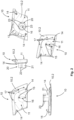
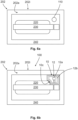
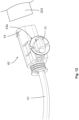
- the Figure 1 shows a door handle module 100 according to the invention before assembly into a ready-to-use module on a handle device 202 of a movable part 201 of a vehicle 200, preferably a commercial vehicle, which is shown below in the Figure 5 is shown schematically.
- the door handle module 100 is characterized in that it includes a housing 10 in which an electronics unit 12 is completely accommodated.
- the housing 10 can, for example, be in two parts with a first housing part 10.1 (see. Figure 3 ) and a second housing part 10.2 (see. Figure 2 ) be trained. There is one in the housing 10 Recording 11 designed to accommodate the electronics unit 12.
- the housing 10 can be in one piece and have an opening through which the electronics unit 12 can be inserted into the receptacle 11.
- the receptacle 11 can be relatively flat in order to accommodate the electronics unit 12 in the form of a circuit board (see Fig. Figures 1 , 2 and 7 ).
- two receiving pins 15 can be provided on the inside of the second housing part 10.2, which can engage in specially designed openings 15a on the circuit board of the electronic unit 12.
- the electronics unit 12 can be hot-sealed using the receiving pins 15 on the second housing part 10.2 in order to arrange the electronics unit 12 captively on the housing 10, possibly over some spacer elements 15b on the receiving pins 15 (production step a), which is based on Figure 7 is explained).
- the housing 10 according to the invention preferably forms a closed and sealed receptacle 11 for the electronics unit 12, in which the electronics unit 12 is reliably protected against weather and mechanical influences.
- an actuation section 19 can be provided, which can indicate the position of a wireless communication element 12b on the electronic unit 12, which is in the Figure 6b is indicated.
- the wireless communication element 12b is intended to improve the functions of the handle device 202 in order to enable wireless actuation of a security system 203 of the vehicle 200, for example to unlock a lock of the movable part 201 without a key (see Fig. Figure 5 ).
- the electronics unit 12 serves to provide a wireless communication capability for a vehicle-external communication unit 50 and the handle device 202 of the movable part 201 of the vehicle 200.
- the vehicle-external communication unit 50 can be designed, for example, in the form of an ID transmitter, a smartphone or the like.
- the electronics unit 12 can receive data, for example identification data, from the vehicle-external communication unit 50 and send it to the security system 203, e.g. B. in the form of an access control system.
- the electronics unit 12 can, for example via the security system 203 of the vehicle 200, trigger an actuation of a lock of the movable part 201 in order to unlock the movable part 201, whereby the movable part 201 for opening using the Handle device 202 will be released.
- the door handle module 100 according to the invention enables remote control of the security system 203 in the form of a keyless go or a keyless entry system. This allows the comfort when operating the security system 203 to be modernized.
- the door handle module 100 according to the invention can improve the safety when operating the security system 203.
- the electronic unit 12 can be used to store driving data, for example a logbook, user profiles or wear-related vehicle data, in order to expand the existing functions in the vehicle 200.
- driving data for example a logbook, user profiles or wear-related vehicle data
- connection element 40 in the form of a cable 41 with a first plug 42 for example in the form of a MolexO plug, is then led through a connection opening 16 in the second housing part 10.2 to the electronic unit 12 (production step b), which is based on the Figure 7 is explained) and connected to the electronic unit 12, in particular soldered (manufacturing step c), which is based on Figure 7 is explained).
- the two housing parts 10.1, 10.2 can be connected and, for example, hot-clamped by means of connecting openings 17 on the second housing part 10.2 and connecting pins 18 on the first housing part 10.1, as is the case Figure 8 indicates (manufacturing step d), which is based on the Figure 8 is explained). It is also conceivable that the connecting openings 17 and the connecting pins 18 can be designed as corresponding fastening elements, for example locking elements, in order to fasten the two housing parts 10.1, 10.2 to one another in a positive and/or non-positive manner. In addition, the housing parts 10.1, 10.2 can be glued to a connecting seam, for example on the edge.
- the receptacle 11 in the housing 10 can be filled with a casting compound (production step e), which is based on the Figure 9 is explained), for which two filler necks 14 can be provided on the back of the second housing part 10.2, which can also serve to center the door handle module 100 on the handle device 202, as shown in the view of Figure 10 is clarified.
- the assembled door handle module 100 is manufactured in the manufacturing steps a) to e), which will be discussed below with reference to Figures 7 to 10 is discussed in detail, as one, Preferably a completely closed and sealed retrofit part is provided, which can be easily, conveniently and without great assembly effort mounted on the handle device 202, which is exemplified in the Figures 6a and 6b is shown.
- the invention provides a relatively flat door handle module 100 so as not to interfere with the design and aerodynamic requirements of the handle device 202.
- the door handle module 100 according to the invention is fastened to the handle device 202 using a fastening adapter 30, which is in the Figures 4 and 10 is shown.
- the fastening adapter 30 can be inserted from the inside of the handle device 202 to attach the door handle module 100 to the handle device 202, as described below in the Figure 10 will be shown.
- a bayonet lock can be produced between the fastening adapter 30 and a connecting element 20 on a second housing part 10.2 of the door handle module 100.
- the fastening adapter 30 and the connecting element 20 can extend through a mounting receptacle 210, for example a lock cylinder receptacle, of the handle device 202, which is in the Figure 6a is shown.
- the fastening adapter 30 itself can be screwed to the inside of the handle device 202, as is the case Figure 10 shows.
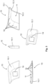
- the Figure 2 shows the second housing part 10.2 alone from different views, namely from top left to bottom right, first from an inside, then from a narrow side, from an outside, from a broad side and in a perspective view.
- the second housing part 10.2 has a substantially flat shape with a likewise flat receptacle 11, in which the electronics unit 12 is received in the form of a circuit board with an attached sensor element 12a and a communication means 12b.
- receiving pins 15 are provided, which can be received in corresponding openings 15a on the circuit board of the electronics unit 12 (production step a), which is in the Figure 7 is shown).
- the outer tips of the receiving pins 15 can be used to hot-stamp the electronics unit 12 on the second housing part 10.2, whereby the electronics unit 12 is securely fastened to the second housing part 10.2.
- the lower approaches of the receiving pins 15 can have rib-like, projecting spacer elements 15b in order to position the electronics unit 12 at a predetermined distance from the inside of the second housing part 10.2. This distance can be used to encapsulate the electronics unit 12 in manufacturing step e), which is based on the Figure 9 is explained.
- the spacer elements 15b ensure more stability of the finished door handle module 100.
- the second housing part 10.2 has a connection opening 16 for the connection element 40, which is designed to be complementary to the first plug 42 of the connection element 40 in order to accommodate the first plug 42, preferably without play.
- two outwardly projecting filler supports 14 are provided on the second housing part 10.2, which on the one hand are used to position or fix the door handle module 100 on the handle device 202 (see Fig. Figure 10 ) and on the other hand serve to fill the receptacle 11 with the casting compound (see manufacturing step e) in the Figure 9 ) can.
- the second housing part 10.2 has a plurality of connection openings 17 on an edge section, which can be used to connect to the connecting pins 18 of the first housing part 10.1, which alone in the Figure 3 is shown.
- An edge arrangement of the connecting openings 17 can serve to correctly position the two housing parts 10.1, 10.2 relative to one another when producing the door handle module 100.
- the second housing part 10.2 is formed with a connecting element 20, which can be formed monolithically and/or of the same material as the second housing part 10.2, for example cast in one piece.
- the connecting element 20 has a substantially cylindrical guide body 21, which can be accommodated coaxially to and within a cylindrical guide section 31 of the fastening adapter 30 during assembly of the door handle module 100 on the handle device 202, as is the case Figure 10 shows.
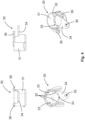
- the fastening adapter 30 is described below in isolation Figure 4 shown.
- Cam or projection-like positioning means 23 are formed radially projecting from the cylindrical guide body 21 of the connecting element 20.
- the positioning means 23 can be inserted into groove-shaped receiving means 33 on the annular receiving element 32 inside of the cylindrical guide section 31 of the fastening adapter 30 intervene when the connecting element 20 is correctly aligned with the fastening adapter 30 in order to carry out a plugging movement of the fastening adapter 30.
- the fastening adapter 30 When pushed onto the cylindrical guide body 21 of the connecting element 20, the fastening adapter 30 can be rotated in order to prevent the plug connection to the connecting element 20 from becoming loose.
- the cam-like or projection-like positioning means 23 leave the groove-shaped receiving means 33 after the fastening adapter 30 has been inserted onto the connecting element 20 and move on the annular receiving element 32 after the fastening adapter 30 has been rotated relative to the connecting element 20.
- the Figure 3 shows the first housing part 10.1 in several views, which closes the receptacle 11 and is arranged on the handle device 202, visible to the outside.
- the first housing part 10.1 has a plurality of laterally arranged connecting pins 18 for connecting to the connecting openings 17 on the second housing part 10.2.
- the first housing part 10.1 has, for example, two laterally arranged undercuts 10.3, under which the second housing part 10.2 can first be pushed in in order to then be lowered onto the connecting pins 18, as is the case Figure 8 indicates.
- a plug-in pivoting movement of the two housing parts 10.1, 10.2 can be carried out relative to one another in order to close the receptacle 11. This movement is predetermined by the undercuts 10.3 and the connecting pins 18, so that the door handle module 100 can be assembled easily and even intuitively.
- An actuating section 19 can be depicted on the outside of the first housing part 10.1 in order to determine the position of the wireless communication means 12b on the electronics unit 12, which is in the Figure 6b is shown to indicate.
- the Figure 4 shows the mounting adapter 30 in several views.
- the fastening adapter 30 has a fastening arm 34 projecting radially from the cylindrical guide section 31 with a fastening means 35 in the form of an opening for a screw 35a in order to screw the fastening adapter 30 to an inside 202i of the handle device 202 (see. Figure 10 ).
- the fastening adapter 30 can be screwed together after the fastening adapter 30 has been pushed in between the opening of the mounting receptacle 210 on the handle device 202 and the outside of the connecting element 20 and twisted in such a way that it is no longer possible to pull out the fastening adapter 30.
- the fastening adapter 30 can have at least one strain relief element 36 in order to wind the cable 41 of the connecting element 40 thereon and absorb the tensile forces, as is the case, for example Figure 10 indicates.
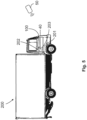
- the Figure 5 shows a commercial vehicle as an example of a vehicle 200, which can be upgraded with the door handle module 100 according to the invention.
- the door handle module 100 according to the invention can be advantageous in order to enable keyless operation of the security system 203 of the vehicle 200 by means of the external communication unit 50 in order to control the movable part 201, for example Shaped like a door that can be unlocked remotely.
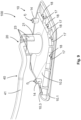
- the Figures 6a and 6b show an exemplary handle device 202 with an outside 202a, to which the housing 10 of the door handle module 100 according to the invention can be attached.
- the handle device 202 can have a handle recess 220 with a handle 330 arranged there, which is formed on an outer shell 240 of the handle device 202.
- the handle 330 can be a rigid or movable handle 330.
- the handle device 202 has a module receptacle 210 in the form of a lock cylinder receptacle, on which the door handle module 100 according to the invention is arranged.
- the module holder 210 is shown schematically below the outer shell 240 and above the handle 230 and the recessed grip 220.
- the door handle module 100 has a recess 10c in the area of the handle recess 220 in order to adapt the door handle module 100 to the outer contour of the handle recess 220 of the handle 230.
- the door handle module 100 completely closes the module receptacle 210 and extends essentially flush with the outer shell 240 of the Handle device 202.
- the housing 10 of the door handle module 100 can be colored or solid-colored in such a way that there is no difference in color to the outer shell 240, the handle 230 and the door handle recess 220.
- the electronics unit 12 can be arranged within the housing 10 of the door handle module 100.
- the electronic unit 12 can have a sensor element 12a as a communication element 12a, which can be designed as a proximity sensor, for example a capacitive sensor.
- the sensor element 12a can serve to detect a user approaching the door handle module 100 in order to wake up the electronics unit 12 for data communication with the vehicle-external communication unit 50, which is in the Figure 5 is shown as an example.
- the electronics unit 12 can have a wireless communication element 12b, which can be designed as an NFC communication element in order to ensure communication between the security system 203 of the vehicle 200 and the vehicle-external communication unit 50, which the user can carry with him.
- FIGS. 7 to 9 serve to illustrate steps a) to e) according to the invention for producing a door handle module 100, which can be designed as described above.
- Contacts 44 are provided for soldering the first plug 42 to the electronics unit 12.
- the electronics unit 12 is fastened in the receptacle 11 and is connected to the first plug 42 of the connection element 40, there remains space around the electronics unit 12 to be cast with a casting compound through the filling supports 14.
- the connection points between the first plug 42 and the contacts 44 on the electronics unit 12 are secured and sealed.
- the Figure 8 shows another step for producing the door handle module 100: d) Fastening the first housing part 10.1 of the housing 10 to the second housing part 10.2 of the housing 10 in order to provide the receptacle 11 for the electronics unit 12.
- the second housing part 10.2 can first be pushed under the undercuts 10.3 on the first housing part 10.1 and then lowered onto the connecting pins 18.
- the two housing parts 10.1, 10.2 can thus carry out a plug-in pivoting movement towards one another in order to close the receptacle 11.
- the arrangement of the undercuts 10.3 and the connecting pins 18 indicates a specific arrangement of the two housing parts 10.1, 10.2 relative to one another, in which they can be fastened to one another. This allows any assembly errors to be avoided.
- the Figure 9 indicates a further step for producing the door handle module 100: e) Filling the receptacle 11 with a casting compound in order to seal at least the electronics unit 12 or a first plug 42 of a connection element 40.
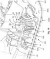
- the Figure 10 shows the door handle module 100 according to the invention in a mounted state on the handle device 202 in a view of an inside 202i of the handle device 202.
- the housing 10 of the door handle module 100 is fixed on the outside 202a of the handle device 202 (see Fig . the filling supports 14, which protrude through corresponding openings in the handle device 202) and are fastened to the handle device 202 by the fastening adapter 30 from the inside 202i of the handle device 202.
- the module receptacle 210, the connecting element 20 and the fastening adapter 30 extend coaxially to one another.
- the housing 10 of the door handle module 100 comes from the outside 202a of the handle device 202 and the fastening arm 34 of the fastening adapter 30 comes from the inside 202i Handle device 202 for support.
- the door handle module 100 is mounted reliably and securely on the handle device 202.
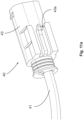
- the Figure 11a shows a connection element 40 with a second plug 43 at a security system-side end of the connection element 40.
- the second plug 43 can have a clip guide 43a in order to fix the connection element 40 on the vehicle 200, preferably in the vicinity of the security system 203.
- the Figure 11b shows a mounting clip 13 designed to complement the clip guide 43a, which can be provided in a set with the door handle module 100 according to the invention.
- the Figure 12 shows the clip guide 43a in engagement with the mounting clip 13.
- one or more guide clips 43b can be provided along the length of the cable 41 of the connection element 40, with an exemplary guide clip 43b in the Figure 10 is shown. Together with the second plug 43, the mounting clip 13 and the guide clips 43b, a complete kit can be provided with which the door handle module 100 is attached to the handle device 202 and the connecting element 40 is easily and conveniently laid on the vehicle 200 and guided up to the security system 203 can.
Landscapes
- Engineering & Computer Science (AREA)
- Mechanical Engineering (AREA)
- Computer Networks & Wireless Communication (AREA)
- Physics & Mathematics (AREA)
- General Physics & Mathematics (AREA)
- Manufacturing & Machinery (AREA)
- Chemical & Material Sciences (AREA)
- Combustion & Propulsion (AREA)
- Transportation (AREA)
- Lock And Its Accessories (AREA)
Description
Die vorliegende Erfindung betrifft ein Türgriffmodul für eine Griffvorrichtung eines beweglichen Teils, wie z. B. einer Tür oder einer Klappe, eines Fahrzeugs, insbesondere eines Nutzfahrzeugs, gemäß dem unabhängigen Vorrichtungsanspruch, ein Verfahren zum Montieren eines Türgriffmoduls an einer Griffvorrichtung gemäß dem entsprechenden unabhängigen Verfahrensanspruch, ein Verfahren zum Herstellen eines Türgriffmoduls für eine Griffvorrichtung gemäß dem entsprechenden unabhängigen Verfahrensanspruch sowie ein Verfahren zum Bereitstellen eines Türgriffmoduls für eine Griffvorrichtung gemäß dem entsprechenden unabhängigen Verfahrensanspruch.The present invention relates to a door handle module for a handle device of a movable part, such as. B. a door or a flap, a vehicle, in particular a commercial vehicle, according to the independent device claim, a method for mounting a door handle module on a handle device according to the corresponding independent method claim, a method for producing a door handle module for a handle device according to the corresponding independent method claim and a method for providing a door handle module for a handle device according to the corresponding independent method claim.
Griffvorrichtungen für Fahrzeuge, wie z.B. aus
Es ist somit eine Aufgabe der Erfindung, die voranstehenden aus dem Stand der Technik bekannten Nachteile zumindest teilweise zu beheben. Insbesondere ist es die Aufgabe der vorliegenden Erfindung, einen erweiterten Funktionsumfang für vorhandene Griffvorrichtungen an Fahrzeugen, insbesondere Nutzfahrzeugen, bereitzustellen und vorzugsweise den Komfort und/oder die Sicherheit bei Sicherheitssystemen, insbesondere bei Zugangskontrollsystemen der Fahrzeuge nachträglich zu verbessern. Weiterhin ist es eine optionale Aufgabe der vorliegenden Erfindung, ein Türgriffmodul für eine Griffvorrichtung eines beweglichen Teils, wie z. B. einer Tür oder einer Klappe, eines Fahrzeugs, insbesondere eines Nutzfahrzeugs, bereitzustellen, welches einfach und kostengünstig in der Herstellung ist, welches einfach und ohne großen Montageaufwand an einer Griffvorrichtung montiert werden kann, welches witterungsbeständig ausgestaltet ist, zuverlässig im Betrieb ist und eine lange Lebensdauer aufweist. Zudem ist es vorzugsweise eine Aufgabe der Erfindung, ein Verfahren zum Montieren eines solchen Türgriffmoduls an einer Griffvorrichtung, ein Verfahren zum Herstellen eines solchen Türgriffmoduls für eine Griffvorrichtung und ein Verfahren zum Bereitstellen eines entsprechenden Türgriffmoduls für eine Griffvorrichtung bereitzustellen.It is therefore an object of the invention to at least partially eliminate the above disadvantages known from the prior art. In particular, the object of the present invention is to provide an expanded range of functions for existing handle devices on vehicles, in particular commercial vehicles, and preferably to subsequently improve the comfort and / or safety of security systems, in particular access control systems of the vehicles. Furthermore, it is an optional object of the present invention to provide a door handle module for a handle device of a movable part, such as. B. a door or a flap, a vehicle, in particular a commercial vehicle, to provide which is simple and inexpensive to manufacture, which can be easily and without great assembly effort on a handle device, which is designed to be weather-resistant, is reliable in operation and a has a long service life. In addition, it is preferably an object of the invention to provide a method for mounting such a door handle module on a handle device, a method for producing such a door handle module for a handle device and a method for providing a corresponding door handle module for a handle device.
Die voranstehende Aufgabe wird gelöst durch ein Türgriffmodul mit den Merkmalen des ersten unabhängigen Vorrichtungsanspruchs, ein Verfahren zum Montieren eines Türgriffmoduls an einer Griffvorrichtung mit den Merkmalen des entsprechenden unabhängigen Verfahrensanspruchs, ein Verfahren zum Herstellen eines Türgriffmoduls für eine Griffvorrichtung mit den Merkmalen des entsprechenden unabhängigen Verfahrensanspruchs sowie ein Verfahren zum Bereitstellen eines Türgriffmoduls für eine Griffvorrichtung mit den Merkmalen des entsprechenden unabhängigen Verfahrensanspruchs.The above object is achieved by a door handle module with the features of the first independent device claim, a method for mounting a door handle module on a handle device with the features of the corresponding independent method claim, a method for producing a door handle module for a handle device with the features of the corresponding independent method claim and a method for providing a door handle module for a handle device with the features of the corresponding independent method claim.
Weitere Merkmale und Details der Erfindung ergeben sich aus den Unteransprüchen, der Beschreibung und den Zeichnungen. Dabei gelten Merkmale und Details, die im Zusammenhang mit dem erfindungsgemäßen Türgriffmodul beschrieben worden sind, selbstverständlich auch im Zusammenhang mit den erfindungsgemäßen Verfahren und jeweils umgekehrt, sodass bezüglich der Offenbarung zu den einzelnen Erfindungsaspekten stets wechselseitig Bezug genommen wird bzw. werden kann.Further features and details of the invention emerge from the subclaims, the description and the drawings. Features and details that have been described in connection with the door handle module according to the invention naturally also apply in connection with the method according to the invention and vice versa, so that reference is or can always be made to each other with regard to the disclosure of the individual aspects of the invention.
Die Erfindung stellt ein Türgriffmodul für eine Griffvorrichtung eines beweglichen Teils, wie z. B. einer Tür oder Klappe, eines Fahrzeugs, insbesondere eines Nutzfahrzeugs, bereit, aufweisend: ein Gehäuse, in welchem eine, insbesondere abgeschlossene, vorzugsweise abgedichtete, Aufnahme ausgebildet ist, in der eine Elektronikeinheit zum Steuern eines Sicherheitssystems des Fahrzeuges angeordnet ist, wobei die Elektronikeinheit mindestens ein Kommunikationselement zum Austauschen von Daten mit einer fahrzeugexternen Kommunikationseinheit aufweist.The invention provides a door handle module for a handle device of a movable part, such as. B. a door or flap, a vehicle, in particular a commercial vehicle, ready, comprising: a housing in which a, in particular closed, preferably sealed, receptacle is formed, in which an electronic unit for controlling a security system of the vehicle is arranged, the Electronic unit has at least one communication element for exchanging data with a vehicle-external communication unit.
Die Elektronikeinheit dient im Rahmen der Erfindung dazu, eine kabellose Kommunikationsfähigkeit mit einer fahrzeugexternen Kommunikationseinheit an der Griffvorrichtung des beweglichen Teils des Fahrzeuges bereitzustellen. Von der fahrzeugexternen Kommunikationseinheit, wie z. B. einem Mobilfunkgerät, Laptop und/oder ID-Geber, kann die Elektronikeinheit Daten, bspw. Identifikationsdaten, empfangen, die die Elektronikeinheit, bspw. zur Überprüfung, an das Sicherheitssystem, z. B. in Form eines Zugangskontrollsystems, weiterleiten kann. Die Weiterleitung der Daten von der Elektronikeinheit zum Sicherheitssystem kann wiederum über ein Kabel erfolgen. Nach einem erfolgreichen Datenaustausch zwischen der fahrzeugexternen Kommunikationseinheit und dem fahrzeugseitigen Sicherheitssystem, bspw. zur Identifikations- bzw. Berechtigungsabfrage, kann die Elektronikeinheit, bspw. über das Sicherheitssystem des Fahrzeuges, eine Betätigung eines Schlosses des beweglichen Teils veranlassen, um das bewegliche Teil zu entriegeln, wodurch das bewegliche Teil zum Öffnen mittels der Griffvorrichtung freigegeben wird. Somit kann das erfindungsgemäße Türgriffmodul eine Fernsteuerung des Sicherheitssystems ermöglichen. Dadurch kann der Komfort beim Bedienen des Sicherheitssystems an die modernen Erfordernisse angepasst und somit verbessert werden. So können z. B. die Fahrer des Fahrzeuges nachträglich (gemeint ist durch die Umrüstung) durch den Einsatz der Erfindung in die Lage versetzt werden, (insbesondere ausschließlich) mit ihrem Mobilfunkgerät das Fahrzeug zu öffnen und ggf. zu starten. Hierzu ist es denkbar, dass dem Fahrer entsprechende Zugangsdaten (bspw. von einer Spedition) für das Fahrzeug drahtlos zu geschickt werden, womit er das Fahrzeug bedienen und fahren kann. Zudem kann durch das erfindungsgemäße Türgriffmodul die Sicherheit beim Bedienen des Sicherheitssystems verbessert werden.Within the scope of the invention, the electronic unit serves to provide wireless communication capability with a vehicle-external communication unit on the handle device of the movable part of the vehicle. From the vehicle-external communication unit, such as B. a mobile device, laptop and / or ID transmitter, the electronic unit can receive data, for example identification data, which the electronic unit, for example for checking, to the security system, e.g. B. in the form of an access control system. The data can be forwarded from the electronic unit to the security system via a cable. After a successful data exchange between the vehicle-external communication unit and the vehicle-side security system, for example for identification or authorization queries, the electronic unit can, for example via the vehicle's security system, cause a lock of the movable part to be actuated in order to unlock the movable part, whereby the movable part is released for opening by means of the handle device. The door handle module according to the invention can thus enable remote control of the security system. This allows the comfort when operating the security system to be adapted to modern requirements and thus improved. For example, B. the driver of the vehicle subsequently (meaning through the conversion) through the use of the invention will be able to open and, if necessary, start the vehicle (in particular exclusively) with their mobile device. For this purpose, it is conceivable that the driver is sent wirelessly corresponding access data (e.g. from a shipping company) for the vehicle, with which he can operate and drive the vehicle. In addition, the door handle module according to the invention can improve safety when operating the security system.
Darüber hinaus ist es im Rahmen der Erfindung denkbar, dass die Elektronikeinheit zur Speicherung von Fahrdaten, bspw. einem Fahrtenbuch, Benutzerprofilen oder verschleißbezogenen Fahrzeugdaten dienen kann, um die vorhandenen Funktionen im Fahrzeug zu erweitern.Furthermore, it is conceivable within the scope of the invention that the electronic unit can be used to store driving data, for example a logbook, user profiles or wear-related vehicle data, in order to expand the existing functions in the vehicle.
Das erfindungsgemäße Türgriffmodul kann vorzugsweise an einer bereits bestehenden und/oder technisch vorhandenen Griffvorrichtung eines Fahrzeugs, insbesondere eines Nutzfahrzeugs, montiert werden, z. B. im Sinne einer Nachrüstung bei Altfahrzeugen oder einer Zusatzausstattung bei Neufahrzeugen. Das erfindungsgemäße Türgriffmodul, insbesondere die Elektronikeinheit, kann die erforderliche Hardware für eine Fernbedienung des Sicherheitssystems mit sich bringen. Außerdem kann das erfindungsgemäße Türgriffmodul, insbesondere die Elektronikeinheit, die erforderliche Software bereitstellen, um ein Fernbedienungssystem nach Art eines Keyless-Go- oder Keyless-Enter-Systems zu ermöglichen. Das Türgriffmodul mit der Elektronikeinheit kann vorteilhafterweise an die vorhandene Fahrzeugelektronik bzw. an das vorhandene Steuersystem der Fahrzeugelektronik angeschlossen werden, um eine vorhandene Zentralverriegelung und ein vorhandenes Sicherheitssystem ansteuern zu können.The door handle module according to the invention can preferably be mounted on an existing and/or technically available handle device of a vehicle, in particular a commercial vehicle, e.g. B. in the sense of retrofitting old vehicles or additional equipment for new vehicles. The door handle module according to the invention, in particular the electronic unit, can provide the necessary hardware for remote control of the security system. In addition, the door handle module according to the invention, in particular the electronic unit, can provide the necessary software to enable a remote control system in the manner of a keyless go or keyless enter system. The door handle module with the electronic unit can advantageously be connected to the existing vehicle electronics or to the existing control system of the vehicle electronics in order to be able to control an existing central locking system and an existing security system.
Die neuen Funktionen werden vorteilhafterweise unter Beibehaltung der geometrischen und aerodynamischen Ausgestaltung der Griffvorrichtung bereitgestellt. Das erfindungsgemäße Türgriffmodul kann dabei designtechnisch und haptisch an die vorhandene Griffvorrichtung des Fahrzeugs angepasst sein, um das Erscheinungsbild der Griffvorrichtung nicht zu beeinträchtigen. Das Türgriffmodul kann bspw. an einer Modulaufnahme der Griffvorrichtung montiert werden. Die Modulaufnahme kann eine bereits vorhandene Aufnahme an der Griffvorrichtung, bspw. eine Schließzylinderaufnahme, oder eine extra dafür herzustellende Aufnahme, bspw. in Form einer Bohrung, sein. Die Aufnahme kann an einem Griff, an einer Griffmulde oder an einer Außenschale der Griffvorrichtung bzw. an einem Teil der Karosserie vorgesehen sein, an welchen die Griffvorrichtung angeordnet ist. Zudem ist es denkbar, dass das Türgriffmodul kraft- und/oder formschlüssig an der Modulaufnahme der Griffvorrichtung befestigt werden kann. Weiterhin kann ein Gehäuse für das Türgriffmodul aus Kunststoff bereitgestellt werden, bspw. aus Polyamid, vorzugsweise Polyamid 6, oder glasfaserverstärkten Kunststoffen. Die sichtbare Seite des Gehäuses kann lackiert, beschichtet oder durchgefärbt sein, um die Optik an das Fahrzeug bzw. an die Griffvorrichtung anzupassen. Das Türgriffmodul kann vorzugsweise zumindest abschnittsweise flächenbündig an der Griffvorrichtung angeordnet werden. Somit kann eine ästhetisch ansprechende Ausgestaltung der Griffvorrichtung erzielt werden. Außerdem können somit die Verletzungsrisiken am Türgriffmodul minimiert werden.The new functions are advantageously provided while maintaining the geometric and aerodynamic design of the handle device. The door handle module according to the invention can be adapted to the existing handle device of the vehicle in terms of design and feel so as not to impair the appearance of the handle device. The door handle module can be mounted, for example, on a module holder of the handle device. The module receptacle can be an existing receptacle on the handle device, for example a lock cylinder receptacle, or a receptacle to be manufactured specifically for this purpose, for example in the form of a hole. The recording can be done on a handle, on a Recessed grip or on an outer shell of the handle device or on a part of the body on which the handle device is arranged. In addition, it is conceivable that the door handle module can be attached to the module holder of the handle device in a force-fitting and/or positive manner. Furthermore, a housing for the door handle module can be provided made of plastic, for example made of polyamide, preferably polyamide 6, or glass fiber reinforced plastics. The visible side of the housing can be painted, coated or colored in order to adapt the appearance to the vehicle or the handle device. The door handle module can preferably be arranged flush with the handle device at least in sections. An aesthetically pleasing design of the handle device can thus be achieved. In addition, the risk of injury to the door handle module can be minimized.
Der Erfindungsgedanke liegt dabei darin, dass das erfindungsgemäße Gehäuse die Elektronikeinheit umschließt, insbesondere dass durch das erfindungsgemäße Gehäuse eine vorzugsweise abgeschlossene und bevorzugt abgedichtete Aufnahme für die Elektronikeinheit bereitgestellt wird, in welcher die Elektronikeinheit gegen äußere Einflüsse, bspw. Feuchtigkeit und/oder Schmutz, zuverlässig und dauerhaft geschützt ist. Das erfindungsgemäße Türgriffmodul wird als ein, vorzugsweise komplett abgeschlossenes und abgedichtetes, Nachrüstteil bereitgestellt, welches einfach, bequem und ohne großen Montageaufwand an der Griffvorrichtung montiert werden kann. Im Rahmen der Erfindung ist es denkbar, dass das Türgriffmodul als ein sehr flaches Modul bereitgestellt wird. Die Befestigung des erfindungsgemäßen Türgriffmoduls kann über einen ursprünglichen Schaft eines mechanischen Schließzylinders der Griffvorrichtung stattfinden. Durch diesen Schaft kann auch ein Anschlusselement, bspw. in Form eines Kabels für die elektrische Verbindung der Elektronikeinheit mit dem Sicherheitssystem des Fahrzeuges durchgeleitet werden. Das Türgriffmodul kann selber über eine Bajonettverbindung mit einem speziellen Befestigungsadapter an der Griffvorrichtung befestigt werden. Dabei kann das Türgriffmodul von außen an der Montageaufnahme und der Befestigungsadapter von innen an der Montageaufnahme angesetzt werden, um miteinander verbunden zu werden. Durch diese Verbindung kann die Befestigung des Türgriffmoduls an der Griffvorrichtung gewährleistet werden. Der Befestigungsadapter kann innenseitig an der Griffvorrichtung verschraubt werden und das Anschlusselement bzw. das Kabel für die Elektronikeinheit durchführen. Denkbar ist, dass der Befestigungsadapter spezielle Klemm- bzw. Zugentlastungselemente für das Kabel aufweisen kann. Das Gehäuse des Türgriffmoduls kann vorzugsweise zweiteilig aufgebaut sein, um die flache Bauweise des Gehäuses zu ermöglichen, in dem die Elektronikeinheit vollständig vom Gehäuse umgeben anordbar ist. Dabei weist das Gehäuse einerseits einen wohlgefälligen Anblick auf und andererseits ist das Gehäuse in sich abgeschlossen, um die Elektronikeinheit geschützt und sicher unterzubringen. Die beiden Gehäuseteile können form- und/oder kraftschlüssig miteinander verbunden und vorzugsweise abgedichtet sein. Zusätzlich können die Gehäuseteile verklebt werden. Um die Elektronikeinheit gegen Feuchtigkeit zu schützen, kann die Aufnahme im Gehäuse mit einer Vergussmasse aufgefüllt werden, wozu zwei Füllstutzen rückseitig am Gehäuseunterteil vorgesehen sein können, die außerdem zur Zentrierung des Türgriffmoduls an der Türgriffvorrichtung dienen können.The idea of the invention is that the housing according to the invention encloses the electronics unit, in particular that the housing according to the invention provides a preferably closed and preferably sealed receptacle for the electronics unit, in which the electronics unit can be reliably protected against external influences, for example moisture and/or dirt and is permanently protected. The door handle module according to the invention is provided as a, preferably completely closed and sealed, retrofit part, which can be mounted on the handle device easily, conveniently and without much assembly effort. Within the scope of the invention, it is conceivable that the door handle module is provided as a very flat module. The door handle module according to the invention can be attached via an original shaft of a mechanical locking cylinder of the handle device. A connection element, for example in the form of a cable, for the electrical connection of the electronic unit to the vehicle's security system can also be passed through this shaft. The door handle module itself can be attached to the handle device via a bayonet connection with a special fastening adapter. The door handle module can be attached to the mounting receptacle from the outside and the fastening adapter can be attached to the mounting receptacle from the inside in order to be connected to one another. This connection can ensure that the door handle module is attached to the handle device. The fastening adapter can be screwed to the inside of the handle device and the connection element or cable for the electronic unit can pass through. It is conceivable that the fastening adapter has special clamping or strain relief elements for the cable may have. The housing of the door handle module can preferably be constructed in two parts in order to enable the flat design of the housing in which the electronics unit can be arranged completely surrounded by the housing. On the one hand, the housing has a pleasing appearance and, on the other hand, the housing is self-contained in order to accommodate the electronic unit in a protected and safe manner. The two housing parts can be connected to one another in a form-fitting and/or force-fitting manner and can preferably be sealed. In addition, the housing parts can be glued. In order to protect the electronic unit against moisture, the receptacle in the housing can be filled with a casting compound, for which purpose two filler necks can be provided on the back of the lower part of the housing, which can also serve to center the door handle module on the door handle device.
Somit wird mithilfe des erfindungsgemäßen Türgriffmoduls ein Nachrüstteil bereitgestellt, um einen erweiterten Funktionsumfang für vorhandene Griffvorrichtungen an Fahrzeugen, insbesondere Nutzfahrzeugen, zu ermöglichen. Ferner wird mithilfe des erfindungsgemäßen Türgriffmoduls der Komfort und/oder die Sicherheit bei Sicherheitssystemen, insbesondere bei Zugangskontrollsystemen der Fahrzeuge verbessert. Das erfindungsgemäße Türgriffmodul ist vorteilhafterweise ein einfaches und kostengünstiges Bauteil, welches einfach und ohne großen Montageaufwand an einer Griffvorrichtung montiert werden kann, welches witterungsbeständig ausgestaltet und zuverlässig im Betrieb ist sowie eine lange Lebensdauer aufweist.Thus, with the help of the door handle module according to the invention, a retrofit part is provided in order to enable an expanded range of functions for existing handle devices on vehicles, in particular commercial vehicles. Furthermore, with the help of the door handle module according to the invention, the comfort and/or safety of security systems, in particular of vehicle access control systems, is improved. The door handle module according to the invention is advantageously a simple and cost-effective component which can be mounted on a handle device easily and without great assembly effort, which is designed to be weather-resistant and is reliable in operation and has a long service life.
Ferner kann die Erfindung bei einem Türgriffmodul vorsehen, dass die Elektronikeinheit mindestens ein Kommunikationselement in Form eines Sensorelementes, insbesondere eines kapazitiven Sensorelementes aufweist, um die Elektronikeinheit zu wecken. Somit kann die Elektronikeinheit energiesparsam betrieben werden. Das Sensorelement kann einen Benutzer in der Umgebung des Türgriffmoduls erfassen und erst dann die Elektronikeinheit, bspw. für eine Berechtigungsabfrage, einschalten. Ein Sensorelement in Form eines kapazitiven Sensorelementes ist vorteilhafterweise ein einfaches und energiesparsames Bauteil, welches sogar ohne eine Energiezufuhr betrieben werden kann.Furthermore, the invention can provide for a door handle module that the electronics unit has at least one communication element in the form of a sensor element, in particular a capacitive sensor element, in order to wake up the electronics unit. The electronic unit can therefore be operated in an energy-saving manner. The sensor element can detect a user in the vicinity of the door handle module and only then switch on the electronic unit, for example for an authorization query. A sensor element in the form of a capacitive sensor element is advantageously a simple and energy-saving component that can even be operated without an energy supply.
Weiterhin kann die Erfindung bei einem Türgriffmodul vorsehen, dass die Elektronikeinheit mindestens ein Kommunikationselement in Form eines drahtlosen Kommunikationselementes, insbesondere eines NFC-, Bluetooth-, Infrarot-, GSM-, LTE-, UMTS-, Mobilfunk-, HF-, UHF-, LF- und/oder WLAN-Kommunikationselementes aufweist, um eine Kommunikation des Sicherheitssystems des Fahrzeuges und der fahrzeugexternen Kommunikationseinheit sicherzustellen. Ein drahtloses Kommunikationselement kann den Komfort beim Bedienen des Sicherheitssystems des Fahrzeuges verbessern. Ein Kommunikationselement in Form eines NFC-Elementes ist vorteilhaft, weil es eine Kommunikation über definierte, begrenzte Distanzen ermöglichen kann. Dies kann die Sicherheit bei der Kommunikation mit der fahrzeugexternen Kommunikationseinheit erheblich erhöhen.Furthermore, the invention can provide for a door handle module that the electronic unit has at least one communication element in the form of a wireless Communication element, in particular an NFC, Bluetooth, infrared, GSM, LTE, UMTS, mobile radio, HF, UHF, LF and / or WLAN communication element, in order to enable communication between the security system of the vehicle and the to ensure communication unit external to the vehicle. A wireless communication element can improve the convenience of operating the vehicle's security system. A communication element in the form of an NFC element is advantageous because it can enable communication over defined, limited distances. This can significantly increase the security of communication with the vehicle-external communication unit.
Des Weiteren kann im Rahmen der Erfindung bei einem Türgriffmodul vorgesehen sein, dass das Gehäuse einteilig oder zweiteilig mit einem ersten Gehäuseteil, welches zumindest zum Abdecken der Aufnahme oder zum sichtbaren Anordnen an der Griffvorrichtung dient, und mit einem zweiten Gehäuseteil ausgebildet ist, welches zumindest zum Befestigen der Elektronikeinheit oder zum Herstellen einer Verbindung des Verbindungselementes mit dem Befestigungsadapter dient. Einteiliges Gehäuse kann vorteilhaft sein, um die Herstellung des Türgriffmoduls zu vereinfachen. Ein zweiteiliges Gehäuse ist vorteilhaft, um ein möglichst flaches Türgriffmodul bereitzustellen, in dem die Elektronikeinheit einfach und bequem untergebracht werden kann.Furthermore, within the scope of the invention, it can be provided for a door handle module that the housing is designed in one piece or in two parts with a first housing part, which serves at least to cover the receptacle or for visible arrangement on the handle device, and with a second housing part, which is at least for Fastening the electronic unit or for establishing a connection of the connecting element to the fastening adapter is used. One-piece housing can be advantageous to simplify the manufacture of the door handle module. A two-part housing is advantageous in order to provide a door handle module that is as flat as possible, in which the electronic unit can be accommodated easily and conveniently.
Zudem ist es denkbar, dass das Gehäuse, insbesondere an einem zweiten Gehäuseteil, mindestens einen, vorzugsweise zwei, Aufnahmepins aufweisen kann, um die Elektronikeinheit am Gehäuse zu befestigen, insbesondere heißzuverstemmen. Somit kann die Elektronikeinheit einfach und bequem in einer durch die Aufnahmepins vorgegebenen Position am Gehäuse befestigt werden. Die Gehäusepins können weiterhin radial abstehende Abstandselemente am Ansatz der Gehäusepins umfassen, um die Elektronikeinheit auf einem bestimmten Abstand zum Gehäuse zu halten. Die Abstandselemente können vorteilhafterweise als Verstärkungsrippen für das Türgriffmodul dienen und außerdem ein Umgießen der Elektronikeinheit von beiden Seiten mit einer Vergussmasse innerhalb des Gehäuses ermöglichen. Dadurch kann die Elektronikeinheit vorteilhafterweise von allen Seiten zuverlässig abgedichtet und außerdem vor mechanischen Einwirkungen geschützt werden.In addition, it is conceivable that the housing, in particular on a second housing part, can have at least one, preferably two, receiving pins in order to fasten the electronics unit to the housing, in particular to heat caulk it. This means that the electronic unit can be easily and conveniently attached to the housing in a position specified by the mounting pins. The housing pins can also include radially projecting spacer elements at the base of the housing pins in order to keep the electronics unit at a certain distance from the housing. The spacer elements can advantageously serve as reinforcing ribs for the door handle module and also enable the electronics unit to be cast around both sides with a casting compound within the housing. As a result, the electronic unit can advantageously be reliably sealed from all sides and also protected from mechanical influences.
Ferner kann die Erfindung bei einem Türgriffmodul vorsehen, dass das Gehäuse, insbesondere an einem zweiten Gehäuseteil, eine Anschlussöffnung für ein Anschlusselement, vorzugsweise für einen ersten Stecker des Anschlusselementes zum Anschließen an der Elektronikeinheit, aufweist. Somit kann ein elektrischer und datentechnischer Anschluss der Elektronikeinheit nach dem Befestigen am Gehäuse bereitgestellt werden. Vorteilhafterweise kann die Anschlussöffnung komplementär zu dem ersten Stecker ausgebildet sein, sodass der Stecker in einer vorgegebenen Position an der Elektronikeinheit abgestützt und dort verlötet werden kann.Furthermore, the invention can provide for a door handle module that the housing, in particular on a second housing part, has a connection opening for a connection element, preferably for a first plug of the connection element for connection to the electronic unit. An electrical and data connection of the electronic unit can thus be provided after it has been attached to the housing. Advantageously, the connection opening can be designed to be complementary to the first plug, so that the plug can be supported in a predetermined position on the electronics unit and soldered there.
Weiterhin kann im Rahmen der Erfindung bei einem Türgriffmodul vorgesehen sein, dass das Gehäuse, insbesondere an einem zweiten Gehäuseteil, mindestens einen, vorzugsweise zwei, Füllstützen aufweist, um zumindest die Aufnahme mit einer Vergussmasse zu füllen oder das Gehäuse an einer Außenseite der Griffvorrichtung zu positionieren. Durch die Füllstutzen kann die Aufnahme um die Elektronikeinheit herum mit der Vergussmasse aufgefüllt werden. Um eine verbesserte Haftfähigkeit der Vergussmasse an zumindest einer inneren Oberfläche des Gehäuses zu erzielen, kann dieses zumindest mechanisch oder chemisch aufgeraut sein. Weiterhin können dieselben Füllstutzen zur Positionierung des Türgriffmoduls an der Griffvorrichtung genutzt werden. Somit kann ein zuverlässig abgedichtetes und leicht zu montierendes Türgriffmodul bereitgestellt werden.Furthermore, within the scope of the invention, it can be provided for a door handle module that the housing, in particular on a second housing part, has at least one, preferably two, filling supports in order to at least fill the receptacle with a casting compound or to position the housing on an outside of the handle device . The filler neck allows the receptacle around the electronics unit to be filled with the casting compound. In order to achieve improved adhesion of the casting compound to at least one inner surface of the housing, it can be roughened at least mechanically or chemically. Furthermore, the same filler necks can be used to position the door handle module on the handle device. A reliably sealed and easy-to-assemble door handle module can thus be provided.
Des Weiteren kann die Erfindung bei einem Türgriffmodul vorsehen, dass das Gehäuse, insbesondere an einem zweiten Gehäuseteil, mindestens eine, vorzugsweise mehrere, bevorzugt einseitig angeordnete, Verbindungsöffnungen aufweist, die mit Verbindungsstiften an einem ersten Gehäuseteil zusammenwirken, um das erste Gehäuseteil am zweiten Gehäuseteil zu befestigen, insbesondere heißzuverstemmen. Dadurch kann auf eine einfache und vorteilhafte Weise eine zuverlässige, vorzugsweise unlösbare Verbindung zwischen dem ersten und dem zweiten Gehäuseteil geschaffen werden. Bei einseitig bzw. unsymmetrisch angeordneten Verbindungsöffnungen kann vorteilhaft sein, dass die Ausrichtung des ersten Gehäuseteils zum zweiten Gehäuseteil vorgegeben werden kann, unter welcher die Gehäuseteile verbunden werden können. Somit kann der Zusammenbau des Türgriffmoduls intuitiv und weniger fehleranfällig gestaltet werden.Furthermore, the invention can provide for a door handle module that the housing, in particular on a second housing part, has at least one, preferably several, preferably one-sided, connecting openings which cooperate with connecting pins on a first housing part in order to close the first housing part on the second housing part fasten, especially hot caulk. This allows a reliable, preferably non-detachable connection to be created between the first and second housing parts in a simple and advantageous manner. In the case of connection openings arranged on one side or asymmetrically, it can be advantageous that the orientation of the first housing part to the second housing part can be specified, under which the housing parts can be connected. This means that the assembly of the door handle module can be designed to be intuitive and less error-prone.
Zudem ist es denkbar, dass das Gehäuse, insbesondere an einem ersten Gehäuseteil einen Betätigungsabschnitt aufweisen kann, um auf mindestens ein Kommunikationselement der Elektronikeinheit insbesondere optisch und/oder taktil hinzuweisen. Dieser Betätigungsabschnitt kann durch Ein- oder Ausprägung an einer Oberfläche des ersten Gehäuseteil vorhanden sein, wobei auch nur der Rand des Betätigungsabschnitts entsprechend markiert sein kann. Somit kann die Bedienung des Türgriffmoduls erleichtert werden und der Benutzer zu einer richtigen Position des Kommunikationselementes geleitet werden, um eine Datenkommunikation mit der Elektronikeinheit einzuleiten.In addition, it is conceivable that the housing, in particular on a first housing part, can have an actuation section in order to indicate at least one communication element of the electronic unit, in particular optically and/or tactilely. This actuation section can be present by imprinting or embossing on a surface of the first housing part, whereby only the edge of the actuation section can be marked accordingly. The operation of the door handle module can thus be made easier and the user can be guided to a correct position of the communication element in order to initiate data communication with the electronic unit.
Außerdem kann im Rahmen der Erfindung bei einem Türgriffmodul vorgesehen sein, dass das Gehäuse, insbesondere an einem ersten Gehäuseteil mindestens einen, vorzugsweise mehrere, bevorzugt einseitig angeordnete, Hinterschnitte aufweist, um das erste Gehäuseteil am zweiten Gehäuseteil zu positionieren. Das zweite Gehäuseteil kann somit zum Verschließen der Aufnahme, vorzugsweise einseitig unter den Hinterschnitten verklemmt und danach nach unten zum ersten Gehäuseteil abgesenkt bzw. verschwenkt werden. Die Hinterschnitte ermöglichen somit einen einfachen Zusammenbau des Türgriffmoduls, bei dem jeder Schritt intuitiv durch die Elemente des Türgriffmoduls vorgegeben werden.Furthermore, within the scope of the invention, it can be provided for a door handle module that the housing, in particular on a first housing part, has at least one, preferably several, preferably one-sided, undercuts in order to position the first housing part on the second housing part. The second housing part can thus be clamped on one side under the undercuts to close the receptacle and can then be lowered or pivoted downwards to the first housing part. The undercuts therefore enable the door handle module to be easily assembled, with each step being intuitively dictated by the elements of the door handle module.
Ferner kann die Erfindung vorsehen, dass ein Anschlusselement, insbesondere in Form eines Kabels mit einem ersten Stecker, insbesondere in Form eines MolexO-Steckers, zum Anschließen an der Elektronikeinheit und einem zweiten Stecker zum Anschließen am Sicherheitssystem des Fahrzeuges, vorgesehen ist. Über das Anschlusselement kann vorteilhafterweise Energie und/oder Daten zwischen der Elektronikeinheit und dem fahrzeugseitigen Sicherheitssystem übertragen werden. Das Kabel kann bspw. in Form eines Datenbusses ausgebildet sein, um eine Kommunikation und/oder einen Datenaustausch zwischen der Elektronikeinheit und dem fahrzeugseitigen Sicherheitssystem zu ermöglichen.Furthermore, the invention can provide that a connection element, in particular in the form of a cable with a first plug, in particular in the form of a MolexO plug, for connecting to the electronic unit and a second plug for connecting to the vehicle's security system, is provided. Energy and/or data can advantageously be transmitted between the electronic unit and the vehicle-side security system via the connection element. The cable can, for example, be designed in the form of a data bus to enable communication and/or data exchange between the electronic unit and the vehicle-side security system.
Weiterhin kann im Rahmen der Erfindung bei einem Türgriffmodul vorgesehen sein, dass ein Anschlusselement, insbesondere an einem zweiten Stecker, eine Clipführung aufweist, um das Anschlusselement am Fahrzeug, vorzugsweise an einem komplementär dazu ausgebildeten Montageclip des Fahrzeuges, zu fixieren, und/oder dass mindestens ein Führungsclip für ein Anschlusselement, insbesondere für ein Kabel des Anschlusselementes, vorgesehen ist, um das Anschlusselement, vorzugsweise das Kabel des Anschlusselementes, am Fahrzeug zu positionieren. Die Clipführung und der Montageclip können in der Nähe des Sicherheitssystems angeordnet werden. Ein oder mehrere Führungsclips können nach Bedarf entlang des Kabels eingesetzt werden. Somit kann die Erfindung einen kompletten Bausatz bereitstellen, mit dem nicht nur das Türgriffmodul an der Griffvorrichtung befestigt, sondern auch das Anschlusselement einfach und bequem am Fahrzeug verlegt und bis hin zum Sicherheitssystem geführt werden kann.Furthermore, within the scope of the invention, it can be provided in a door handle module that a connection element, in particular on a second plug, has a clip guide in order to fix the connection element on the vehicle, preferably on a complementary mounting clip of the vehicle, and / or that at least a guide clip for a connection element, in particular for a cable Connection element, is provided to position the connection element, preferably the cable of the connection element, on the vehicle. The clip guide and mounting clip can be placed close to the security system. One or more guide clips can be inserted along the cable as required. The invention can therefore provide a complete kit with which not only the door handle module can be attached to the handle device, but also the connecting element can be easily and conveniently laid on the vehicle and guided all the way to the security system.
Des Weiteren kann im Rahmen der Erfindung bei einem Türgriffmodul vorgesehen sein, dass ein, insbesondere separater, Befestigungsadapter zum Einsetzten von einer Innenseite der Griffvorrichtung vorgesehen ist. Mithilfe des Befestigungsadapters kann ein abgeschlossenes Gehäuse des Türgriffmoduls von einer Außenseite der Griffvorrichtung angeordnet werden, wobei zum Befestigen des Türgriffmoduls nur der Befestigungsadapter von der Innenseite der Griffvorrichtung angeordnet werden muss.Furthermore, within the scope of the invention, it can be provided in a door handle module that a, in particular separate, fastening adapter is provided for insertion from an inside of the handle device. Using the fastening adapter, a closed housing of the door handle module can be arranged from an outside of the handle device, with only the fastening adapter having to be arranged from the inside of the handle device in order to fasten the door handle module.
Zudem kann die Erfindung bei einem Türgriffmodul vorsehen, dass am Gehäuse ein Verbindungselement zum Einsetzen von einer Außenseite der Griffvorrichtung vorgesehen ist, welches insbesondere materialeinheitlich und/oder monolithisch mit dem Gehäuse ausgebildet sein kann. Somit kann ein komplementäres Element zum Befestigungsadapter bereitgestellt werden, um eine Verbindung zwischen dem Gehäuse und dem Befestigungsadapter herzustellen. Dazwischen kann sich eine Außenschale der Griffmulde oder der Außenschale der Griffvorrichtung erstrecken, die zwischen dem Befestigungsadapter und dem Gehäuse des Türgriffmoduls eingeklemmt werden kann.In addition, in the case of a door handle module, the invention can provide that a connecting element is provided on the housing for insertion from an outside of the handle device, which can in particular be made of the same material and/or monolithic with the housing. Thus, a complementary element to the mounting adapter can be provided to establish a connection between the housing and the mounting adapter. In between, an outer shell of the recessed grip or the outer shell of the handle device can extend, which can be clamped between the fastening adapter and the housing of the door handle module.
Außerdem ist es im Rahmen der Erfindung denkbar, dass das Türgriffmodul über eine Verbindung eines gehäuseseitigen Verbindungselementes mit einem, vorzugsweise separaten, Befestigungsadapter an der Griffvorrichtung befestigbar ist. Somit kann der Vorteil erreicht werden, dass keine Zusammenwirkung des erfindungsgemäßen Türgriffmoduls mit der Griffmulde oder der Außenschale der Griffvorrichtung erforderlich ist, um die Elektronikeinheit geschützt unterzubringen. Vielmehr kann ein bereits abgeschlossenes und abgedichtetes Gehäuse des Türgriffmoduls an der Griffvorrichtung befestigt werden. Hierzu kann das Türgriffmodul an einer Montageaufnahme der Griffvorrichtung, bspw. einer Schließzylinderaufnahme, vorzugsweise anstatt des Schließzylinders, eingesetzt werden und von innen mit dem Befestigungsadapter befestigt werden. Vorteilhafterweise können der Befestigungsadapter und das Verbindungselement zumindest bereichsweise zylinderförmig ausgebildet sein und koaxial ineinander eingesetzt werden, um ebenfalls koaxial durch eine Modulaufnahme der Griffvorrichtung eingeführt zu werden.In addition, it is conceivable within the scope of the invention that the door handle module can be attached to the handle device via a connection of a housing-side connecting element with a, preferably separate, fastening adapter. The advantage can thus be achieved that no interaction of the door handle module according to the invention with the handle recess or the outer shell of the handle device is required in order to accommodate the electronic unit in a protected manner. Rather, an already closed and sealed housing of the door handle module can be attached to the handle device. For this purpose, the door handle module can be attached to a mounting receptacle of the handle device, for example a lock cylinder receptacle, preferably instead of Locking cylinder, can be inserted and fastened from the inside with the fastening adapter. Advantageously, the fastening adapter and the connecting element can be cylindrical at least in some areas and inserted coaxially into one another in order to also be inserted coaxially through a module receptacle of the handle device.
Ferner kann die Erfindung vorsehen, dass ein, vorzugsweise separater, Befestigungsadapter zum Herstellen mindestens einer form- und/oder kraftschlüssigen Verbindung, einer Steck-Dreh-Verbindung, eines Bajonettverschlusses, eines Schraubverschlusses oder eines Rastverschlusses, mit einem gehäuseseitigen Verbindungselement ausgebildet ist. Dadurch kann eine einfache und schnelle Montage des Türgriffmoduls an der Griffvorrichtung ermöglicht werden.Furthermore, the invention can provide that a, preferably separate, fastening adapter for producing at least one positive and/or non-positive connection, a plug-turn connection, a bayonet lock, a screw lock or a snap lock, is designed with a housing-side connecting element. This enables simple and quick assembly of the door handle module on the handle device.
Weiterhin ist es denkbar, dass ein, vorzugsweise separater, Befestigungsadapter einen, insbesondere zumindest abschnittsweise zylindrischen, Führungsabschnitt aufweist, welcher in einer Modulaufnahme, vorzugsweise in einer Schließzylinderaufnahme, der Griffvorrichtung aufnehmbar ist, und/oder dass ein, vorzugsweise separater, Befestigungsadapter geometrisch komplementär zu einer Modulaufnahme, insbesondere zu einer Schließzylinderaufnahme, der Griffvorrichtung ausgebildet ist. Vorteilhafterweise kann dadurch eine bereits vorhandene Modulaufnahme an der Griffvorrichtung genutzt werden, um das Türgriffmodul daran zu befestigen. Somit braucht die vorhandene Griffvorrichtung nicht umgebaut werden, und die Aufrüstung der Griffvorrichtung kann kostengünstig sowie mit wenig Aufwand erfolgen.Furthermore, it is conceivable that a, preferably separate, fastening adapter has a, in particular at least partially cylindrical, guide section, which can be accommodated in a module receptacle, preferably in a lock cylinder receptacle, of the handle device, and / or that a, preferably separate, fastening adapter is geometrically complementary a module receptacle, in particular a lock cylinder receptacle, the handle device is designed. Advantageously, an existing module holder on the handle device can be used to attach the door handle module to it. This means that the existing handle device does not need to be converted, and the handle device can be upgraded inexpensively and with little effort.
Des Weiteren kann im Rahmen der Erfindung bei einem Türgriffmodul vorgesehen sein, dass ein, vorzugsweise separater, Befestigungsadapter, insbesondere innerhalb eines Führungsabschnitts, ein, vorzugsweise im Wesentlichen ringförmiges, Aufnahmeelement aufweist, der derart ausgebildet ist, um eine Verbindung eines gehäuseseitigen Verbindungselementes mit dem Befestigungsadapter in nur einer vorgegebenen Ausrichtung des Verbindungselementes zum Befestigungsadapter zu ermöglichen. Somit kann die Richtigkeit der Montage gewährleistet werden und der Monteur darüber eine haptische Rückmeldung erhalten.Furthermore, within the scope of the invention, it can be provided in a door handle module that a, preferably separate, fastening adapter, in particular within a guide section, has a, preferably substantially annular, receiving element, which is designed in such a way as to connect a housing-side connecting element to the fastening adapter in just one predetermined orientation of the connecting element to the fastening adapter. This means that the correctness of the assembly can be guaranteed and the fitter can receive haptic feedback.
Zudem ist es möglich, dass ein, vorzugsweise separater, Befestigungsadapter, insbesondere an einem Aufnahmeelement, mindestens ein, vorzugsweise nutförmiges, Aufnahmemittel für ein, vorzugsweise nockenförmiges, Positioniermittel an einem gehäuseseitigen Verbindungselement aufweist. Wenn die Positioniermittel in die Aufnahmemittel eingreifen, kann das Verbindungselement in den Befestigungsadapter eingesteckt werden. Somit kann die Verbindung eines gehäuseseitigen Verbindungselementes mit dem Befestigungsadapter in nur einer vorgegebenen Ausrichtung des Verbindungselementes zum Befestigungsadapter ermöglicht werden.In addition, it is possible for a, preferably separate, fastening adapter, in particular on a receiving element, to have at least one, preferably groove-shaped, receiving means for a, preferably cam-shaped, positioning means on a housing-side connecting element. When the positioning means engage with the receiving means, the connecting element can be inserted into the fastening adapter. The connection of a housing-side connecting element to the fastening adapter can thus be made possible in only a predetermined orientation of the connecting element to the fastening adapter.
Außerdem kann ein, vorzugsweise separater, Befestigungsadapter im Rahmen der Erfindung zumindest einen, insbesondere außenseitig an einem Führungsabschnitt abstehenden, Befestigungsarm aufweisen, um den Befestigungsadapter an der Griffvorrichtung form- und/oder kraftschlüssig zu befestigen, und/oder dass ein, vorzugsweise separater, Befestigungsadapter, insbesondere an einem Befestigungsarm, ein Befestigungsmittel, bevorzugt in Form einer Aufnahmeöffnung für eine Schraube oder in Form eines Rastelementes für ein komplementäres Gegenrastelement der Griffvorrichtung, aufweist. Somit kann der Befestigungsadapter von der Innenseite der Griffvorrichtung einfach und bequem befestigt werden, wodurch das Türgriffmodul verlierfest an der Griffvorrichtung befestigt wird.In addition, a, preferably separate, fastening adapter within the scope of the invention can have at least one fastening arm, in particular protruding on the outside of a guide section, in order to fasten the fastening adapter to the handle device in a positive and/or non-positive manner, and/or that a, preferably separate, fastening adapter , in particular on a fastening arm, has a fastening means, preferably in the form of a receiving opening for a screw or in the form of a locking element for a complementary counter-locking element of the handle device. The fastening adapter can thus be easily and conveniently fastened from the inside of the handle device, whereby the door handle module is securely attached to the handle device.
Ferner kann ein, vorzugsweise separater, Befestigungsadapter im Rahmen eines erfindungsgemäßen Türgriffmoduls mindestens ein, insbesondere außenseitig an einem Führungsabschnitt abstehendes, Zugentlastungselement für ein Anschlusselement, insbesondere für ein Kabel des Anschlusselementes, aufweisen. Somit kann das Anschlusselement zuverlässig an der Elektronikeinheit angeschlossen werden, ohne die Gefahr entstehen zu lassen, dass Zugkräfte an die Verbindungsstellen zur Elektronikeinheit weitergeleitet werden und die Verbindung des Anschlusselementes mit der Elektronikeinheit unterbrochen oder gelöst wird.Furthermore, a, preferably separate, fastening adapter in the context of a door handle module according to the invention can have at least one strain relief element, in particular projecting on the outside of a guide section, for a connection element, in particular for a cable of the connection element. The connection element can therefore be reliably connected to the electronic unit without the risk of tensile forces being passed on to the connection points to the electronic unit and the connection of the connection element to the electronic unit being interrupted or loosened.
Weiterhin kann im Rahmen der Erfindung bei einem Türgriffmodul vorgesehen sein, dass ein gehäuseseitiges Verbindungselement einen, insbesondere zumindest abschnittsweise zylindrischen, Führungskörper aufweist, welches in einem Befestigungsadapter, insbesondere innerhalb eines Führungsabschnitts, aufnehmbar ist, und/oder dass ein gehäuseseitiges Verbindungselement geometrisch komplementär zu einem, vorzugsweise separaten, Befestigungsadapter ausgebildet ist. Somit kann eine einfache und schnelle Montage des Türgriffmoduls an der Griffvorrichtung ermöglicht werden.Furthermore, within the scope of the invention, it can be provided for a door handle module that a housing-side connecting element has a guide body, in particular at least partially cylindrical, which can be received in a fastening adapter, in particular within a guide section, and / or that a Housing-side connecting element is geometrically complementary to a, preferably separate, fastening adapter. This makes it possible to mount the door handle module on the handle device quickly and easily.
Des Weiteren kann die Erfindung bei einem Türgriffmodul vorsehen, dass ein gehäuseseitiges Verbindungselement, insbesondere außenseitig, mindestens ein, vorzugsweise nockenförmiges, Positioniermittel aufweist, welches mit einem Aufnahmeelement, insbesondere mit einem nutförmigen Aufnahmemittel, an einem, vorzugsweise separaten, Befestigungsadapter in eine mechanische Wirkverbindung bringbar ist, um die Verbindung des Verbindungselementes mit dem Befestigungsadapter in nur einer vorgegebenen Ausrichtung des Verbindungselementes zum Befestigungsadapter zu ermöglichen. Somit kann ein Einstecken des Verbindungselementes in den Befestigungsadapter ermöglicht werden. Weiterhin kann dadurch ein Verdrehen des Befestigungsadapters bezüglich des Verbindungselementes ermöglicht werden, um eine Steck-Dreh-Verbindung zwischen dem Verbindungselement und dem Befestigungsadapter herzustellen.Furthermore, the invention can provide for a door handle module that a housing-side connecting element, in particular on the outside, has at least one, preferably cam-shaped, positioning means, which can be brought into a mechanical operative connection with a receiving element, in particular with a groove-shaped receiving means, on a, preferably separate, fastening adapter is to enable the connection of the connecting element to the fastening adapter in only a predetermined orientation of the connecting element to the fastening adapter. This makes it possible to insert the connecting element into the fastening adapter. Furthermore, this makes it possible to rotate the fastening adapter with respect to the connecting element in order to establish a plug-and-turn connection between the connecting element and the fastening adapter.
Ferner wird die erfindungsgemäße Aufgabe durch ein Verfahren zum Montieren eines Türgriffmoduls an einer Griffvorrichtung eines beweglichen Teil eines Fahrzeugs, insbesondere eines Nutzfahrzeugs, gelöst, wobei das Türgriffmodul zum Austauschen von Daten mit einer fahrzeugexternen Kommunikationseinheit und zum Steuern eines Sicherheitssystems des Fahrzeuges, insbesondere wie oben beschrieben, ausgebildet ist, wobei ein Gehäuse des Türgriffmoduls an einer Außenseite der Griffvorrichtung fixiert und durch einen Befestigungsadapter von einer Innenseite der Griffvorrichtung an der Griffvorrichtung befestigt wird. Somit kann ein bereits abgeschlossenes und abgedichtetes Gehäuse an der Außenseite der Griffvorrichtung positioniert werden, in dem die Elektronikeinheit geschützt vor Witterungseinflüssen und vor mechanischen Einwirkungen untergebracht werden kann. Zum Befestigen des Gehäuses des Türgriffmoduls braucht nur noch der Befestigungsadapter von der Innenseite der Griffvorrichtung positioniert und mit dem Gehäuse des Türgriffmoduls befestigt werden. Dadurch kann eine einfache und schnelle Montage des Türgriffmoduls an der Griffvorrichtung ermöglicht werden. Weiterhin werden mithilfe des erfindungsgemäßen Verfahrens zum Montieren des Türgriffmoduls an der Griffvorrichtung die gleichen Vorteile erreicht, die oben im Zusammenhang mit dem erfindungsgemäßen Türgriffmodul beschrieben wurden. Auf diese Vorteile wird vorliegend vollumfänglich Bezug genommen.Furthermore, the object according to the invention is achieved by a method for mounting a door handle module on a handle device of a movable part of a vehicle, in particular a commercial vehicle, wherein the door handle module is used to exchange data with a communication unit external to the vehicle and to control a security system of the vehicle, in particular as described above , is designed, wherein a housing of the door handle module is fixed to an outside of the handle device and is fastened to the handle device by a fastening adapter from an inside of the handle device. An already closed and sealed housing can thus be positioned on the outside of the handle device, in which the electronics unit can be accommodated protected from the effects of the weather and mechanical influences. To attach the housing of the door handle module, the fastening adapter only needs to be positioned from the inside of the handle device and attached to the housing of the door handle module. This enables simple and quick assembly of the door handle module on the handle device. Furthermore, using the method according to the invention for mounting the door handle module on the handle device, the same advantages are achieved that are mentioned above in connection with Door handle module according to the invention were described. These advantages are fully referenced here.
Weiterhin kann die Erfindung bei einem Verfahren zum Montieren des Türgriffmoduls an der Griffvorrichtung vorsehen, dass das Türgriffmodul durch Herstellen einer form- und/oder kraftschlüssigen Verbindung, insbesondere einer Steck-Dreh-Verbindung, vorzugsweise eines Bajonettverschlusses, Schraubverschlusses oder Rastverschlusses, eines, insbesondere materialeinheitlich und/oder monolithisch mit dem Gehäuse ausgebildeten, Verbindungselementes des Gehäuses mit dem Befestigungsadapter an der Griffvorrichtung befestigt wird. Die Montage des Türgriffmoduls an der Griffvorrichtung kann somit einfach und in nur wenigen Schritten erfolgen.Furthermore, in a method for mounting the door handle module on the handle device, the invention can provide that the door handle module is made by producing a positive and/or non-positive connection, in particular a plug-turn connection, preferably a bayonet lock, screw lock or snap lock, in particular of the same material and / or monolithically formed with the housing, connecting element of the housing is attached to the handle device with the fastening adapter. The door handle module can therefore be mounted on the handle device easily and in just a few steps.
Des Weiteren wird die erfindungsgemäße Aufgabe durch ein Verfahren zum Herstellen eines Türgriffmoduls für eine Griffvorrichtung eines beweglichen Teils eines Fahrzeugs, insbesondere eines Nutzfahrzeugs, gelöst, wobei das Türgriffmodul zum Austauschen von Daten mit einer fahrzeugexternen Kommunikationseinheit und zum Steuern eines Sicherheitssystems des Fahrzeuges, insbesondere wie oben beschrieben, ausgebildet ist, wobei ein Gehäuse für das Türgriffmodul bereitgestellt wird, in welchem eine, insbesondere abgeschlossene, vorzugsweise abgedichtete, Aufnahme mit einer Elektronikeinheit zum Steuern des Sicherheitssystems des Fahrzeuges ausgebildet wird, wobei die Elektronikeinheit mindestens ein Kommunikationselement zum Austauschen von Daten mit einer fahrzeugexternen Kommunikationseinheit aufweist. Mithilfe des Verfahrens zum Herstellen des Türgriffmoduls für die Griffvorrichtung werden die gleichen Vorteile erreicht, die und/oben im Zusammenhang mit dem erfindungsgemäßen Türgriffmodul und/oder dem Verfahren zum Montieren eines entsprechenden Türgriffmoduls an einer Griffvorrichtung beschrieben wurden, auf die vorliegend vollumfänglich Bezug genommen wird.Furthermore, the object according to the invention is achieved by a method for producing a door handle module for a handle device of a movable part of a vehicle, in particular a commercial vehicle, wherein the door handle module is used to exchange data with a communication unit external to the vehicle and to control a security system of the vehicle, in particular as above described, is designed, wherein a housing is provided for the door handle module, in which a, in particular closed, preferably sealed, receptacle is formed with an electronics unit for controlling the security system of the vehicle, the electronics unit having at least one communication element for exchanging data with a vehicle-external Has communication unit. With the help of the method for producing the door handle module for the handle device, the same advantages are achieved that were described above in connection with the door handle module according to the invention and/or the method for mounting a corresponding door handle module on a handle device, to which full reference is made here.
Ein Verfahren zum Herstellen eines Türgriffmoduls für eine Griffvorrichtung kann zudem im Sinne der Erfindung mindestens einen der folgenden Schritte aufweisen:
- a) Montieren der Elektronikeinheit an einem zweiten Gehäuseteil des Gehäuses,
- b) Einführen eines ersten Steckers eines Anschlusselementes durch ein Verbindungselement an einem zweiten Gehäuseteil des Gehäuses, oder
- c) Anschließen, insbesondere Verlöten, eines ersten Steckers eines Anschlusselementes an der Elektronikeinheit.
- a) mounting the electronic unit on a second housing part of the housing,
- b) inserting a first plug of a connection element through a connecting element on a second housing part of the housing, or
- c) connecting, in particular soldering, a first plug of a connection element to the electronic unit.
Durch den Schritt a) kann eine verlierfeste Befestigung der Elektronikeinheit am Gehäuse, insbesondere in der Aufnahme des Gehäuses ermöglicht werden. Durch den Schritt b) kann ein elektrischer und ein Daten-Anschluss an die Elektronikeinheit bereitgestellt werden, der nach innen des Fahrzeuges bis hin zum Sicherheitssystem des Fahrzeuges verlegt werden kann. Durch den Schritt c) kann eine übertragungssichere und dauerhafte Anbindung des Anschlusselementes an die Elektronikeinheit ermöglicht werden.Step a) enables a captive attachment of the electronic unit to the housing, in particular in the receptacle of the housing. Through step b), an electrical and a data connection can be provided to the electronic unit, which can be routed inside the vehicle up to the vehicle's security system. Step c) enables a transfer-safe and permanent connection of the connection element to the electronic unit.
Ferner ist es denkbar, dass ein Verfahren zum Herstellen eines Türgriffmoduls für eine Griffvorrichtung mindestens einen weiteren Schritt aufweist:
d) Befestigen eines ersten Gehäuseteils des Gehäuses an einem zweiten Gehäuseteil des Gehäuses, um die Aufnahme für die Elektronikeinheit bereitzustellen.Furthermore, it is conceivable that a method for producing a door handle module for a handle device has at least one further step:
d) attaching a first housing part of the housing to a second housing part of the housing in order to provide the receptacle for the electronic unit.
Durch zwei Gehäuseteile kann ein besonders flaches Türgriffmodul bereitgestellt werden, in dem die Elektronikeinheit, bspw. in Form einer Platine untergebracht werden kann. Ein flaches Türgriffmodul kann besonders elegant und sicher an die geometrischen und aerodynamischen Eigenschaften der Griffvorrichtung angepasst werden, um bei Fahrtwind zuverlässig an der Griffvorrichtung zu verbleiben und keine unangenehmen Klappergeräusche zu erzeugen.Two housing parts can be used to provide a particularly flat door handle module in which the electronic unit can be accommodated, for example in the form of a circuit board. A flat door handle module can be adapted particularly elegantly and safely to the geometric and aerodynamic properties of the handle device in order to remain reliably on the handle device when the wind is blowing and not to produce any unpleasant rattling noises.
Weiterhin ist es im Rahmen der Erfindung möglich, dass ein Verfahren zum Herstellen eines Türgriffmoduls für eine Griffvorrichtung mindestens einen weiteren Schritt aufweist:
e) Auffüllen der Aufnahme mit einer Vergussmasse, um mindestens die Elektronikeinheit oder einen ersten Stecker eines Anschlusselementes abzudichten.Furthermore, it is possible within the scope of the invention for a method for producing a door handle module for a handle device to have at least one further step:
e) Filling the receptacle with a casting compound in order to seal at least the electronic unit or a first plug of a connection element.
Somit können die elektrischen und elektronischen Komponenten der Elektronikeinheit von allen Seiten zuverlässig abgedichtet werden.This means that the electrical and electronic components of the electronic unit can be reliably sealed from all sides.
Des Weiteren wird die erfindungsgemäße Aufgabe durch Verfahren zum Bereitstellen eines Türgriffmoduls für eine Griffvorrichtung eines beweglichen Teils eines Fahrzeugs, insbesondere eines Nutzfahrzeugs, gelöst, wobei das Türgriffmodul zum Austauschen von Daten mit einer fahrzeugexternen Kommunikationseinheit und zum Steuern eines Sicherheitssystems des Fahrzeuges, insbesondere wie oben beschrieben, ausgebildet ist, wobei das Verfahren mindestens einen Schritt eines oben beschriebenen Verfahrens zum Herstellen des Türgriffmoduls und/oder mindestens einen Schritt eines oben beschriebenen Verfahrens zum Montieren des Türgriffmoduls an der Griffvorrichtung umfasst. Mithilfe des Verfahrens zum Bereitstellen des Türgriffmoduls für die Griffvorrichtung werden die gleichen Vorteile erreicht, die und/oben im Zusammenhang mit dem erfindungsgemäßen Türgriffmodul und/oder den Verfahren zum Montieren und/oder Herstellen eines entsprechenden Türgriffmoduls an einer Griffvorrichtung beschrieben wurden, auf die vorliegend vollumfänglich Bezug genommen wird.Furthermore, the object according to the invention is achieved by a method for providing a door handle module for a handle device of a movable part of a vehicle, in particular a commercial vehicle, wherein the door handle module is used to replace Data with a vehicle-external communication unit and for controlling a security system of the vehicle, in particular as described above, is designed, wherein the method involves at least one step of a method described above for producing the door handle module and / or at least one step of a method described above for assembling the door handle module the handle device includes. With the help of the method for providing the door handle module for the handle device, the same advantages are achieved that were described above in connection with the door handle module according to the invention and/or the method for assembling and/or producing a corresponding door handle module on a handle device, which are fully covered here is referred to.
Weitere, die Erfindung verbessernde Maßnahmen ergeben sich aus der nachfolgenden Beschreibung von Ausführungsbeispielen der Erfindung, welche in den Figuren schematisch dargestellt sind. Sämtliche aus den Ansprüchen, der Beschreibung oder den Zeichnungen hervorgehenden Merkmale und/oder Vorteile, einschließlich konstruktiver Einzelheiten, räumliche Anordnung und Verfahrensschritte, können sowohl für sich als auch in den verschiedensten Kombinationen erfindungswesentlich sein. Dabei ist zu beachten, dass die Figuren nur beschreibenden Charakter haben und nicht dazu gedacht sind, die Erfindung in irgendeiner Form einzuschränken.Further measures improving the invention result from the following description of exemplary embodiments of the invention, which are shown schematically in the figures. All features and/or advantages arising from the claims, the description or the drawings, including constructive details, spatial arrangement and method steps, can be essential to the invention both individually and in a wide variety of combinations. It should be noted that the figures are only descriptive and are not intended to limit the invention in any way.
Es zeigen:
- Figur 1
- ein erfindungsgemäßes Türgriffmodul in einer Explosionsansicht,
- Figur 2
- ein zweites Gehäuseteil eines erfindungsgemäßen Türgriffmoduls,
- Figur 3
- ein erstes Gehäuseteil eines erfindungsgemäßen Türgriffmoduls,
- Figur 4
- einen Befestigungsadapter eines erfindungsgemäßen Türgriffmoduls,
- Figur 5
- ein Fahrzeug mit einem erfindungsgemäßen Türgriffmodul,
- Figur 6a
- eine Griffvorrichtung mit einer Modulaufnahme,
- Figur 6b
- eine Griffvorrichtung mit einem erfindungsgemäßen Türgriffmodul,
- Figur 7
- ein erstes Gehäuseteil des erfindungsgemäßen Türgriffmoduls mit einer eingesetzten Elektronikeinheit,
- Figur 8
- Zusammensetzten eines ersten Gehäuseteils und eines zweiten Gehäuseteils eines erfindungsgemäßen Türgriffmoduls,
- Figur 9
- Auffüllen einer Aufnahme zwischen einem ersten Gehäuseteil und einem zweiten Gehäuseteil eines erfindungsgemäßen Türgriffmoduls mit einer Vergussmasse,
Figur 10- ein erfindungsgemäßes Türgriffmodul in einem befestigten Zustand an einer Griffvorrichtung in einer Ansicht von einer Innenseite der Griffvorrichtung,
- Figur 11a
- ein zweiter Stecker eines Anschlusselementes mit einer Clipführung,
- Figur 11b
- ein Montageclip für eine Clipführung an einem zweiten Stecker eines Anschlusselementes, und
Figur 12- ein zweiter Stecker eines Anschlusselementes mit einer Clipführung im Zusammengriff mit einem Montageclip.
- Figure 1
- a door handle module according to the invention in an exploded view,
- Figure 2
- a second housing part of a door handle module according to the invention,
- Figure 3
- a first housing part of a door handle module according to the invention,
- Figure 4
- a fastening adapter of a door handle module according to the invention,
- Figure 5
- a vehicle with a door handle module according to the invention,
- Figure 6a
- a handle device with a module holder,
- Figure 6b
- a handle device with a door handle module according to the invention,
- Figure 7
- a first housing part of the door handle module according to the invention with an inserted electronic unit,
- Figure 8
- Assembling a first housing part and a second housing part of a door handle module according to the invention,
- Figure 9
- Filling a receptacle between a first housing part and a second housing part of a door handle module according to the invention with a casting compound,
- Figure 10
- a door handle module according to the invention in an attached state on a handle device in a view from an inside of the handle device,
- Figure 11a
- a second plug of a connection element with a clip guide,
- Figure 11b
- a mounting clip for a clip guide on a second plug of a connection element, and
- Figure 12
- a second plug of a connection element with a clip guide in conjunction with a mounting clip.
In den nachfolgenden Figuren werden für die gleichen technischen Merkmale auch für unterschiedliche Ausführungsbeispiele die identischen Bezugszeichen verwendet.In the following figures, identical reference numerals are used for the same technical features and for different exemplary embodiments.
Die
Die Elektronikeinheit 12 dient erfindungsgemäß dazu, eine kabellose Kommunikationsfähigkeit einer fahrzeugexternen Kommunikationseinheit 50 und der Griffvorrichtung 202 des beweglichen Teils 201 des Fahrzeuges 200 bereitzustellen. Die fahrzeugexterne Kommunikationseinheit 50 kann bspw. in Form eines ID-Gebers, eines Smartphones oder dergleichen ausgebildet sein. Von der fahrzeugexternen Kommunikationseinheit 50 kann die Elektronikeinheit 12 Daten, bspw. Identifikationsdaten, empfangen und an das Sicherheitssystem 203, z. B. in Form eines Zugangskontrollsystems, weiterleiten. Nach einer verifizierten Berechtigung eines Benutzers durch die fahrzeugexterne Kommunikationseinheit 50 beim fahrzeugseitigen Sicherheitssystem 203 kann die Elektronikeinheit 12, bspw. über das Sicherheitssystem 203 des Fahrzeuges 200, eine Betätigung eines Schlosses des beweglichen Teils 201 veranlassen, um das bewegliche Teil 201 zu entriegeln, wodurch das bewegliche Teil 201 zum Öffnen mittels der Griffvorrichtung 202 freigeben wird. Denkbar ist, dass mittels des erfindungsgemäßen Türgriffmoduls 100 eine Fernsteuerung des Sicherheitssystems 203 in Form eines Keyless-Go- oder eines Keyless-Entry-Systems ermöglicht wird. Dadurch kann der Komfort beim Bedienen des Sicherheitssystems 203 modernisiert werden. Zudem kann durch das erfindungsgemäße Türgriffmodul 100 die Sicherheit beim Bedienen des Sicherheitssystems 203 verbessert werden.According to the invention, the
Darüber hinaus kann die Elektronikeinheit 12 zur Speicherung von Fahrdaten, bspw. einem Fahrtenbuch, Benutzerprofilen oder verschleißbezogenen Fahrzeugdaten dienen, um die vorhandenen Funktionen im Fahrzeug 200 zu erweitern.In addition, the
Anschließend wird durch eine Anschlussöffnung 16 im zweiten Gehäuseteil 10.2 ein Anschlusselement 40 in Form eines Kabels 41 mit einem ersten Stecker 42, bspw. in Form eines MolexO-Steckers, zu Elektronikeinheit 12 geführt (Herstellungs-Schritt b), welcher anhand der
Die beiden Gehäuseteile 10.1, 10.2 können mittels Verbindungsöffnungen 17 am zweiten Gehäuseteil 10.2 und Verbindungsstifte 18 am ersten Gehäuseteil 10.1 verbunden und bspw. heißverklemmt werden, wie es die
Das zusammengebaute Türgriffmodul 100 wird in den Herstellungs-Schritten a) bis e), auf die im Nachfolgenden anhand der
Die
Zudem weist das zweite Gehäuseteil 10.2 eine Anschlussöffnung 16 für das Anschlusselement 40, welche komplementär zum ersten Stecker 42 des Anschlusselementes 40 ausgebildet ist, um den ersten Stecker 42, vorzugsweise spielfrei, aufzunehmen.In addition, the second housing part 10.2 has a
Weiterhin sind am zweiten Gehäuseteil 10.2 bspw. zwei nach außen ragende Füllstützen 14 vorgesehen, die einerseits zum Positionieren bzw. Fixieren des Türgriffmoduls 100 an der Griffvorrichtung 202 (s.
Ferner weist das zweite Gehäuseteil 10.2 an einem Randabschnitt mehrere Verbindungsöffnungen 17 auf, die zum Verbinden mit den Verbindungsstiften 18 des ersten Gehäuseteils 10.1 dienen können, welches in Alleinstellung in der
Außenseitig ist das zweite Gehäuseteil 10.2 mit einem Verbindungselement 20 ausgebildet, welches monolithisch und/oder materialeinheitlich mit dem zweiten Gehäuseteil 10.2 ausgeformt, bspw. in einem Stück gegossen werden kann.On the outside, the second housing part 10.2 is formed with a connecting
Das Verbindungselement 20 weist einen im Wesentlichen zylindrischen Führungskörper 21 auf, welcher koaxial zu einem und innerhalb eines zylindrischen Führungsabschnittes 31 des Befestigungsadapters 30 bei der Montage des Türgriffmoduls 100 an der Griffvorrichtung 202 aufgenommen werden kann, wie es die
Radial abstehend vom zylindrischen Führungskörper 21 des Verbindungselementes 20 sind nocken- bzw. vorsprungartige Positioniermittel 23 ausgebildet. Die Positioniermittel 23 können in nutförmige Aufnahmemittel 33 am ringförmigen Aufnahmeelement 32 innerhalb des zylindrischen Führungsabschnittes 31 des Befestigungsadapters 30 eingreifen, wenn das Verbindungselement 20 richtig zum Befestigungsadapter 30 ausgerichtet ist, um eine Steckbewegung des Befestigungsadapters 30 auszuführen. Aufgeschoben auf den zylindrischen Führungskörper 21 des Verbindungselementes 20 kann der Befestigungsadapter 30 verdreht werden, um ein Lösen der Steckverbindung zum Verbindungselement 20 zu verhindern. Die nocken- bzw. vorsprungartige Positioniermittel 23 verlassen die nutförmigen Aufnahmemittel 33 nach dem Einstecken des Befestigungsadapters 30 auf das Verbindungselement 20 und verschieben sich auf dem ringförmigen Aufnahmeelement 32 nach dem Verdrehen des Befestigungsadapters 30 relativ zum Verbindungselement 20. Somit wird eine form- und/oder kraftschlüssige Verbindung nach Art einer Steck-Dreh-Verbindung bzw. eines Bajonettverschlusses zwischen dem Befestigungsadapter 30 und dem Verbindungselement 20 gebildet.Cam or projection-like positioning means 23 are formed radially projecting from the
Die
Außenseitig am ersten Gehäuseteil 10.1 kann ein Betätigungsabschnitt 19 abgebildet sein, um die Position des drahtlosen Kommunikationsmittels 12b an der Elektronikeinheit 12, welches in der
Die
Die
Die
Innerhalb des Gehäuses 10 des Türgriffmoduls 100 ist die Elektronikeinheit 12 angeordnet sein. Die Elektronikeinheit 12 kann ein Sensorelement 12a als ein Kommunikationselement 12a aufweisen, welches als ein Näherungssensor, bspw. ein kapazitiver Sensor ausgebildet sein kann. Das Sensorelement 12a kann dazu dienen, eine Annäherung eines Benutzers an das Türgriffmodul 100 zu detektieren, um die Elektronikeinheit 12 für eine Datenkommunikation mit der fahrzeugexternen Kommunikationseinheit 50 zu wecken, die in der
Die
Wie es die
- a) Montieren der Elektronikeinheit 12 am zweiten Gehäuseteil 10.2 des
Gehäuses 10, - b) Einführen des ersten Steckers 42 des Anschlusselementes 40
durch das Verbindungselement 20 am zweiten Gehäuseteil 10.2 desGehäuses 10, - c) Anschließen, insbesondere Verlöten, des ersten Steckers 42 des Anschlusselementes 40 an
der Elektronikeinheit 12.
- a) mounting the
electronic unit 12 on the second housing part 10.2 of thehousing 10, - b) inserting the
first plug 42 of theconnection element 40 through the connectingelement 20 on the second housing part 10.2 of thehousing 10, - c) connecting, in particular soldering, the
first plug 42 of theconnection element 40 to theelectronics unit 12.
Zum Verlöten des ersten Steckers 42 an der Elektronikeinheit 12 sind Kontakte 44 vorgesehen. Wenn die Elektronikeinheit 12 in der Aufnahme 11 befestigt ist und an den ersten Stecker 42 des Anschlusselementes 40 angeschlossen ist, bleibt um die Elektronikeinheit 12 herum Platz, um durch die Füllstützen 14 mit einer Vergussmasse umgossen zu werden. Durch Auffüllen der Aufnahme 11 mit der Vergussmasse können außerdem die Verbindungsstellen zwischen dem ersten Stecker 42 und den Kontakten 44 an der Elektronikeinheit 12 abgesichert und abgedichtet werden.
Die
d) Befestigen des ersten Gehäuseteils 10.1 des Gehäuses 10 am zweiten Gehäuseteil 10.2 des Gehäuses 10, um die Aufnahme 11 für die Elektronikeinheit 12 bereitzustellen.The
d) Fastening the first housing part 10.1 of the
Dabei kann das zweite Gehäuseteil 10.2 zunächst unter die Hinterschnitte 10.3 am ersten Gehäuseteil 10.1 reingeschoben werden und danach auf die Verbindungsstifte 18 abgesenkt werden. Somit können die beiden Gehäuseteile 10.1, 10.2 eine Steck-Schwenk-Bewegung zueinander ausführen, um die Aufnahme 11 zu verschließen. Die Anordnung der Hinterschnitte 10.3 und der Verbindungsstifte 18 gibt eine bestimmte Anordnung der beiden Gehäuseteile 10.1, 10.2 zueinander an, in der sie aneinander befestigt werden können. Etwaige Montagefehler können dadurch vermieden werden.The second housing part 10.2 can first be pushed under the undercuts 10.3 on the first housing part 10.1 and then lowered onto the connecting pins 18. The two housing parts 10.1, 10.2 can thus carry out a plug-in pivoting movement towards one another in order to close the
Die
e) Auffüllen der Aufnahme 11 mit einer Vergussmasse, um mindestens die Elektronikeinheit 12 oder einen ersten Stecker 42 eines Anschlusselementes 40 abzudichten.The
e) Filling the
Die
Die
Zudem können ein oder mehrere Führungsclips 43b der Länge nach des Kabels 41 des Anschlusselementes 40 vorgesehen sein, wobei ein beispielhafter Führungsclip 43b in der
Die voranstehende Erläuterung der Ausführungsformen beschreibt die vorliegende Erfindung ausschließlich im Rahmen von Beispielen. Selbstverständlich können einzelne Merkmale der Ausführungsformen, sofern technisch sinnvoll, frei miteinander kombiniert werden, ohne den Rahmen der vorliegenden Erfindung zu verlassen.The above explanation of the embodiments describes the present invention solely in terms of examples. Of course, individual features of the embodiments can, if technically sensible, be freely combined with one another without departing from the scope of the present invention.
- 100100
- TürgriffmodulDoor handle module
- 1010
- GehäuseHousing
- 10.110.1
- erstes Gehäuseteilfirst housing part
- 10.210.2
- zweites Gehäuseteilsecond housing part
- 10.310.3
- HinterschnittUndercut
- 10c10c
- Aussparungrecess
- 1111
- AufnahmeRecording
- 1212
- ElektronikeinheitElectronics unit
- 12a12a
- SensorelementSensor element
- 12b12b
- drahtloses Kommunikationselementwireless communication element
- 1313
- MontageclipMounting clip
- 1414
- FüllstützeFilling support
- 1515
- AufnahmepinRecording pin
- 15a15a
- Öffnung für AufnahmepinOpening for recording pin
- 15b15b
- AbstandselementSpacer element
- 1616
- AnschlussöffnungConnection opening
- 1717
- Verbindungsöffnungconnection opening
- 1818
- Verbindungsstiftconnecting pin
- 1919
- BetätigungsabschnittOperating section
- 2020
- Verbindungselementconnecting element
- 2121
- Führungskörperleadership body
- 2323
- PositioniermittelPositioning means
- 3030
- BefestigungsadapterMounting adapter
- 3131
- FührungsabschnittLeadership section
- 3232
- AufnahmeelementRecording element
- 3333
- AufnahmemittelRecording means
- 3434
- BefestigungsarmMounting arm
- 3535
- BefestigungsmittelFasteners
- 35a35a
- Schraubescrew
- 3636
- ZugentlastungselementStrain relief element
- 4040
- AnschlusselementConnection element
- 4141
- KabelCable
- 4242
- erster Steckerfirst plug
- 4343
- zweiter Steckersecond plug
- 43a43a
- ClipführungClip guide
- 43b43b
- FührungsclipGuide clip
- 4444
- Kontaktecontacts
- 5050
- KommunikationseinheitCommunication unit
- 200200
- Fahrzeugvehicle
- 201201
- bewegliches Teilmoving part
- 202202
- GriffvorrichtungHandle device
- 202a202a
- AußenseiteOutside
- 202i202i
- Innenseiteinside
- 203203
- Sicherheitssystemsecurity system
- 210210
- ModulaufnahmeModule recording
- 220220
- Griffmulderecessed grip
- 230230
- GriffHandle
- 240240
- AußenschaleOuter shell
Claims (15)
- Door handle module (100) for a handle device (202) of a movable part (201) of a vehicle (200), in particular a commercial vehicle, comprising:a housing (10) in which a receptacle (11) is formed,in which an electronic unit (12) for controlling a safety system (203) of the vehicle (200) is arranged,wherein the electronic unit (12) comprises at least one communication element (12a, 12b) for exchanging data with a communication unit (50) external to the vehicle,characterized in thatthe door handle module (100) is designed to be mounted on a module receptacle (210) of the handle device (202), which is designed in the form of an already existing receptacle on the handle device (202), a lock cylinder receptacle or a receptacle in the form of a bore to be produced specially for this purpose.
- Door handle module (100) according to the preceding claim,
characterized in thatthe electronic unit (12) has at least one communication element (12a, 12b) in the form of a sensor element (12a), in particular a capacitive sensor element, for waking up the electronic unit (12),and/or in that the electronics unit (12) has at least one communication element (12a, 12b) in the form of a wireless communication element (12b), in particular an NFC, Bluetooth, infrared, GSM, LTE, UMTS, mobile radio, HF, UHF, LF and/or WLAN communication element, in order to ensure communication of the security system (203) of the vehicle (200) and the communication unit (50) external to the vehicle. - Door handle module (100) according to any one of the preceding claims,
characterized in thatthe housing (10) is formed in one piece or in two pieces with a first housing part (10.1), which is used at least for covering the receptacle (11) or for visible arrangement on the handle device (202), and with a second housing part (10.2), which is used at least for fastening the electronic unit (12) or for producing a connection of the connecting element (20) to the fastening adapter (30),and/or in that the housing (10), in particular on a second housing part (10.2), has at least one, preferably two, locating pins (15) in order to fasten the electronics unit (12) to the housing (10), in particular to heat caulk it,and/or in that the housing (10) has, in particular on a second housing part (10.2), a connection opening (16) for a connection element (40), preferably for a first plug (42) of the connection element (40) for connection to the electronics unit (12),and/or in that the housing (10), in particular on a second housing part (10.2), has at least one, preferably two, filling supports (14) in order to fill at least the receptacle (11) with a potting compound or to position the housing (10) on an outer side (202a) of the handle device (202). - Door handle module (100) according to any one of the preceding claims,
characterized in thatthe housing (10) has, in particular on a second housing part (10.2), at least one, preferably a plurality of, preferably unilaterally arranged, connecting openings (17) which interact with connecting pins (18) on a first housing part (10.1) in order to fasten the first housing part (10.1) to the second housing part (10.2), in particular to heat caulk it,and/or in that the housing (10) has, in particular on a first housing part (10.1), an actuating section (19) for indicating the at least one communication element (12a, 12b) of the electronic unit (12),and/or in that the housing (10) has, in particular on a first housing part (10.1), at least one, preferably a plurality of undercuts (10.3), preferably arranged on one side, in order to position the first housing part (10.1) on the second housing part (10.2). - Door handle module (10) according to any one of the preceding claims,
characterized in that
a connection element (40), in particular in the form of a cable (41) with a first plug (42), in particular in the form of a latching plug, for connection to the electronic unit (12) and a second plug (43) for connection to the safety system (203) of the vehicle (200), is provided, and/or in that a connection element (40), in particular on a second connector (43), has a clip guide (43a) in order to fix the connection element (40) to the vehicle (200), preferably to a mounting clip (13) of the vehicle (200) which is designed to be complementary thereto, and/or in that at least one guide clip (43b) is provided for a connection element (40), in particular for a cable (41) of the connection element (40), in order to position the connection element (40), preferably the cable (41) of the connection element (40), on the vehicle (200). - Door handle module (100) according to the preceding claim,
characterized in that,a fastening adapter (30), in particular a separate fastening adapter (30), is provided for insertion from an inner side (202i) of the handle device (202),and/or in that a connecting element (20), in particular of unitary material and/or monolithically formed with the housing (10), is provided on the housing (10) for insertion from an outer side (202a) of the handle device (202),and/or in that the door handle module (100) can be fastened to the handle device (202) via a connection of a housing-side connecting element (20) to a, preferably separate, fastening adapter (30),wherein in particular a, preferably separate, fastening adapter (30) is formed for producing at least one positive and/or non-positive connection, a plug-and-turn connection, a bayonet lock, a screw lock or a snap-in lock, with a connecting element (20) on the housing side,and/or in that a, preferably separate, fastening adapter (30) has a guide section (31), in particular cylindrical at least in sections, which can be accommodated in a module receptacle (210), preferably in a lock cylinder receptacle, of the handle device (202),and/or that a, preferably separate, fastening adapter (30) is geometrically complementary to a module receptacle (210), in particular to a lock cylinder receptacle, of the handle device (202). - Door handle module (100) according to any one of the preceding claims,
characterized in thata, preferably separate, fastening adapter (30), in particular within a guide section (31), has a, preferably substantially annular, receiving element (32) which is designed in such a way as to enable a connection of a housing-side connecting element (20) to the fastening adapter (30) in only one predetermined alignment of the connecting element (20) with respect to the fastening adapter (30),and/or in that a, preferably separate, fastening adapter (30), in particular on a receiving element (32), has at least one, preferably groove-shaped, receiving means (33) for a, preferably cam-shaped, positioning means (23) on a housing-side connecting element (20). - Door handle module (100) according to any one of the preceding claims,
characterized in thata, preferably separate, fastening adapter (30) has at least one fastening arm (34), projecting in particular from the outside on a guide section (31), in order to fasten the fastening adapter (30) to the handle device (202) in a form-fitting and/or force-fitting manner,and/or in that a, preferably separate, fastening adapter (30), in particular on a fastening arm (34), has a fastening means (35), preferably in the form of a receiving opening for a screw (35a) or in the form of a latching element for a complementary counter-latching element of the handle device (202). - Door handle module (100) according to any one of the preceding claims,
characterized in that
a, preferably separate, fastening adapter (30) has at least one strain relief element (36), in particular projecting on the outside on a guide section (31), for a connecting element (40), in particular for a cable (41) of the connecting element (40). - Door handle module (100) according to any one of the preceding claims,
characterized in thata housing-side connecting element (20) has a guide body (21), in particular cylindrical at least in sections, which can be accommodated in a fastening adapter (30), in particular within a guide section (31),and/or in that a housing-side connecting element (20) is geometrically complementary to a, preferably separate, fastening adapter (30),and/or in that a housing-side connecting element (20) has, in particular on the outside, at least one, preferably cam-shaped, positioning means (23) which can be brought into mechanical operative connection with a receiving element (32), in particular with a groove-shaped receiving means (33), on a, preferably separate, fastening adapter (30), in order to allow the connecting element (20) to be connected to the fastening adapter (30) in only one predetermined alignment of the connecting element (20) with respect to the fastening adapter (30). - Method for mounting a door handle module (100) on a handle device (202) of a movable part (201) of a vehicle (200), in particular of a commercial vehicle (200), wherein the door handle module (100) is designed for exchanging data with a communication unit (50) external to the vehicle and for controlling a safety system (203) of the vehicle (200) according to one of the preceding claims,
wherein a housing (10) of the door handle module (100) is fixed to an outer side (202a) of the handle device (202) and is fixed to the handle device (202) by a fixing adapter (30) from an inner side (202i) of the handle device (202). - A method according to the preceding claim,
characterized in that
the door handle module (100) is fastened to the handle device (202) by producing a positive and/or non-positive connection, in particular a plug-in/rotary connection, preferably a bayonet lock, screw lock or latch lock, of a connecting element (20) of the housing (10), which connecting element (20) is, in particular, of unitary material and/or monolithic design with the housing (10), to the fastening adapter (30). - Method for producing a door handle module (100) for a handle device (202) of a movable part (201) of a vehicle (200), in particular a commercial vehicle (200), wherein the door handle module (100) according to one of the preceding claims is designed for exchanging data with a communication unit (50) external to the vehicle and for controlling a safety system (203) of the vehicle (200),wherein a housing (10) is provided for the door handle module (100), in which a receptacle (11) is formed with an electronic unit (12) for controlling the security system (203) of the vehicle (200),wherein the electronic unit (12) comprises at least one communication element (12a, 12b) for exchanging data with a communication unit (50) external to the vehicle.
- Method according to any one of the preceding claims,
characterized in thatthe method comprises at least one of the following steps:a) mounting the electronics unit (12) on a second housing part (10.2) of the housing (10),b) inserting a first plug (42) of a connecting element (40) through a connecting element (20) at a second housing part (10.2) of the housing (10), orc) connecting, in particular soldering, a first connector (42) of a connection element (40) to the electronics unit (12),and/or that the method comprises at least one further step:
d) attaching a first housing part (10.1) of the housing (10) to a second housing part (10.2) of the housing (10) to provide the receptacle (11) for the electronics unit (12),and/or that the method comprises at least one further step:
e) filling the receptacle (11) with a potting compound to seal at least the electronics unit (12) or a first connector (42) of a connecting element (40). - Method for providing a door handle module (100) for a handle device (202) of a movable part (201) of a vehicle (200), in particular of a commercial vehicle (200), wherein the door handle module (100) is designed for exchanging data with a communication unit (50) external to the vehicle and for controlling a safety system (203) of the vehicle (200) according to one of the preceding claims,
wherein the method comprises at least one of a method of manufacturing the door handle module (100) according to any one of the preceding claims, or a method of mounting the door handle module (100) to the handle device (202) according to any one of the preceding claims.
Applications Claiming Priority (1)
| Application Number | Priority Date | Filing Date | Title |
|---|---|---|---|
| DE102017117926.7A DE102017117926A1 (en) | 2017-08-07 | 2017-08-07 | Door handle module |
Publications (2)
| Publication Number | Publication Date |
|---|---|
| EP3441266A1 EP3441266A1 (en) | 2019-02-13 |
| EP3441266B1 true EP3441266B1 (en) | 2023-10-11 |
Family
ID=63144892
Family Applications (1)
| Application Number | Title | Priority Date | Filing Date |
|---|---|---|---|
| EP18187266.4A Active EP3441266B1 (en) | 2017-08-07 | 2018-08-03 | Door handle module |
Country Status (4)
| Country | Link |
|---|---|
| US (1) | US10753127B2 (en) |
| EP (1) | EP3441266B1 (en) |
| CN (1) | CN109386192A (en) |
| DE (1) | DE102017117926A1 (en) |
Families Citing this family (7)
| Publication number | Priority date | Publication date | Assignee | Title |
|---|---|---|---|---|
| DE102016110345A1 (en) * | 2016-06-03 | 2017-12-07 | Huf Hülsbeck & Fürst Gmbh & Co. Kg | Additional door handle module for a door handle unit |
| US11091094B2 (en) * | 2018-05-15 | 2021-08-17 | Glory Creative, Inc. | Capacitive sensing car-door pre-opening warning device based on a flexible printed circuit |
| PL3715182T3 (en) | 2019-03-28 | 2022-04-19 | Hella Gutmann Solutions GmbH | Adapter |
| DE102019124217A1 (en) * | 2019-06-11 | 2020-12-17 | Huf Hülsbeck & Fürst Gmbh & Co. Kg | arrangement |
| DE102020213055A1 (en) | 2020-10-15 | 2022-04-21 | Volkswagen Aktiengesellschaft | Unlocking system for a vehicle door with rotating connection |
| US11745676B2 (en) * | 2022-01-10 | 2023-09-05 | Kiekert Ag | Motor vehicle locking device |
| DE102022111437A1 (en) | 2022-05-09 | 2023-11-09 | Rehau Automotive Se & Co. Kg | Method for error-free assembly of an electronic component |
Family Cites Families (19)
| Publication number | Priority date | Publication date | Assignee | Title |
|---|---|---|---|---|
| JPS6261856A (en) * | 1985-09-12 | 1987-03-18 | Yazaki Corp | Wiring device assembled with functions for automobile |
| DE59811066D1 (en) * | 1997-10-14 | 2004-04-29 | Huf Huelsbeck & Fuerst Gmbh | LOCKING DEVICE, IN PARTICULAR FOR MOTOR VEHICLES |
| JP3648396B2 (en) * | 1998-12-02 | 2005-05-18 | トヨタ自動車株式会社 | Vehicle door handle |
| JP2000313288A (en) * | 1999-04-30 | 2000-11-14 | Yazaki Corp | Circuit connection structure of vehicle wiring harness |
| DE19943989C1 (en) * | 1999-09-14 | 2001-04-05 | Kostal Leopold Gmbh & Co Kg | Mounting module for automobile door components has component reception recess formed in surface of carrier acting as part of housing of supported component |
| TWI236599B (en) * | 2000-06-02 | 2005-07-21 | Yamaha Corp | Multimedia system with synchronization of music and image tracks |
| JP3566943B2 (en) * | 2001-07-02 | 2004-09-15 | アイシン精機株式会社 | Vehicle door handle |
| JP4342207B2 (en) * | 2003-04-22 | 2009-10-14 | アイシン精機株式会社 | Vehicle door handle device |
| DE10348719A1 (en) * | 2003-10-16 | 2005-05-12 | Huf Huelsbeck & Fuerst Gmbh | Outside door handle, especially for vehicles, contains transmission and excitation electrodes associated with capacitive locking and unlocking sensors |
| DE102004038569B3 (en) * | 2004-08-06 | 2005-10-20 | Huf Huelsbeck & Fuerst Gmbh | An automobile door handle |
| DE602007000993D1 (en) * | 2006-03-16 | 2009-06-10 | Aisin Seiki | Door handle device for vehicles |
| DE102006025075A1 (en) * | 2006-05-30 | 2007-12-06 | Hella Kgaa Hueck & Co. | Capacitive sensor e.g. sensor device for keyless entry system, has two electrodes and sensor electronic with power supply is formed as earth cable where later electrode is formed from section of earth cable |
| WO2008137634A1 (en) * | 2007-05-03 | 2008-11-13 | Donnelly Corporation | Illumination module for a vehicle |
| DE102008054526A1 (en) * | 2008-12-11 | 2010-06-17 | Huf Hülsbeck & Fürst Gmbh & Co. Kg | Door handle assembly for a motor vehicle |
| JP5556620B2 (en) * | 2010-11-26 | 2014-07-23 | アイシン精機株式会社 | Door handle device |
| CN205015482U (en) * | 2015-07-21 | 2016-02-03 | 武汉中瀚科技有限公司 | On -vehicle positioner |
| DE102016110345A1 (en) * | 2016-06-03 | 2017-12-07 | Huf Hülsbeck & Fürst Gmbh & Co. Kg | Additional door handle module for a door handle unit |
| EP3566306A1 (en) * | 2016-11-22 | 2019-11-13 | Huf Hülsbeck & Fürst GmbH & Co. KG | Door handle with a sensor system |
| DE102017110145A1 (en) * | 2017-04-28 | 2018-10-31 | Huf Hülsbeck & Fürst Gmbh & Co. Kg | Vehicle door handle with antenna arrangement |
-
2017
- 2017-08-07 DE DE102017117926.7A patent/DE102017117926A1/en not_active Withdrawn
-
2018
- 2018-08-01 CN CN201810864415.1A patent/CN109386192A/en active Pending
- 2018-08-03 EP EP18187266.4A patent/EP3441266B1/en active Active
- 2018-08-07 US US16/056,572 patent/US10753127B2/en not_active Expired - Fee Related
Also Published As
| Publication number | Publication date |
|---|---|
| EP3441266A1 (en) | 2019-02-13 |
| US20190040660A1 (en) | 2019-02-07 |
| DE102017117926A1 (en) | 2019-02-07 |
| CN109386192A (en) | 2019-02-26 |
| US10753127B2 (en) | 2020-08-25 |
Similar Documents
| Publication | Publication Date | Title |
|---|---|---|
| EP3441266B1 (en) | Door handle module | |
| EP2668062B1 (en) | Locking device, in particular for a plug | |
| EP2212502B1 (en) | Door actuator with an actuator unit | |
| EP3111029B1 (en) | Door-handle system for vehicles | |
| DE102015209851A1 (en) | Motor vehicle door and door handle system for such a motor vehicle door | |
| EP3630555B1 (en) | Container device for accommodating an id transmitter, insert for accommodating an id transmitter, and method for actuating an id transmitter | |
| DE4008834C1 (en) | Interrogator for car door lock - has switch trip coupled to cylinder and connected to adjacent control switch | |
| DE102012100428A1 (en) | Door handle for motor car, has printed circuit board, antenna, and sensor activated when motor car is locked, and another sensor activated when motor car is unlocked, fastened outside at shell, and electrically directly connected with board | |
| WO2017001130A1 (en) | Door-handle system for vehicles | |
| EP1766165A1 (en) | Device for actuating a lock integrated in a door, hatch, or similar, especially in a vehicle | |
| DE10060447B4 (en) | Interior mirror arrangement | |
| WO2017207296A1 (en) | Additional door handle module for a door handle unit | |
| EP2318225B1 (en) | Door arrangement and assembly method for a door arrangement | |
| EP2998485B1 (en) | Rotary knob for actuating a cylinder adapter of a closing cylinder | |
| EP3845727B1 (en) | Door handle for a vehicle | |
| DE10037760A1 (en) | Reset device for a switch of a motor vehicle | |
| WO2017220259A1 (en) | Handle for a movable component of a motor vehicle | |
| EP3044040B1 (en) | Component carrier | |
| DE19961370A1 (en) | Outside door handle arrangement for a motor vehicle door, motor vehicle door and method for assembling an outside door handle | |
| DE102015111937A1 (en) | Turn knob for actuating a cylinder adapter of a lock cylinder | |
| DE19842225A1 (en) | Motor vehicle steering column module | |
| DE10110303A1 (en) | Door closure unit for vehicle, has coupling mechanism which includes connecting lead for signaling or illumination | |
| EP2998465B1 (en) | Fitting for a building door and method for same | |
| DE102012101338A1 (en) | Wiper blade mounting bracket, has pair of vertical parts extending from system parts perpendicular to mounting portion, and collar portion arranged on vertical parts and projecting outwardly from vertical parts | |
| EP2998482A1 (en) | Rotary knob for actuating a cylinder adapter of a closing cylinder |
Legal Events
| Date | Code | Title | Description |
|---|---|---|---|
| PUAI | Public reference made under article 153(3) epc to a published international application that has entered the european phase |
Free format text: ORIGINAL CODE: 0009012 |
|
| STAA | Information on the status of an ep patent application or granted ep patent |
Free format text: STATUS: THE APPLICATION HAS BEEN PUBLISHED |
|
| AK | Designated contracting states |
Kind code of ref document: A1 Designated state(s): AL AT BE BG CH CY CZ DE DK EE ES FI FR GB GR HR HU IE IS IT LI LT LU LV MC MK MT NL NO PL PT RO RS SE SI SK SM TR |
|
| AX | Request for extension of the european patent |
Extension state: BA ME |
|
| STAA | Information on the status of an ep patent application or granted ep patent |
Free format text: STATUS: REQUEST FOR EXAMINATION WAS MADE |
|
| 17P | Request for examination filed |
Effective date: 20190813 |
|
| RBV | Designated contracting states (corrected) |
Designated state(s): AL AT BE BG CH CY CZ DE DK EE ES FI FR GB GR HR HU IE IS IT LI LT LU LV MC MK MT NL NO PL PT RO RS SE SI SK SM TR |
|
| STAA | Information on the status of an ep patent application or granted ep patent |
Free format text: STATUS: EXAMINATION IS IN PROGRESS |
|
| 17Q | First examination report despatched |
Effective date: 20211014 |
|
| GRAP | Despatch of communication of intention to grant a patent |
Free format text: ORIGINAL CODE: EPIDOSNIGR1 |
|
| STAA | Information on the status of an ep patent application or granted ep patent |
Free format text: STATUS: GRANT OF PATENT IS INTENDED |
|
| INTG | Intention to grant announced |
Effective date: 20230320 |
|
| GRAS | Grant fee paid |
Free format text: ORIGINAL CODE: EPIDOSNIGR3 |
|
| GRAA | (expected) grant |
Free format text: ORIGINAL CODE: 0009210 |
|
| STAA | Information on the status of an ep patent application or granted ep patent |
Free format text: STATUS: THE PATENT HAS BEEN GRANTED |
|
| AK | Designated contracting states |
Kind code of ref document: B1 Designated state(s): AL AT BE BG CH CY CZ DE DK EE ES FI FR GB GR HR HU IE IS IT LI LT LU LV MC MK MT NL NO PL PT RO RS SE SI SK SM TR |
|
| REG | Reference to a national code |
Ref country code: GB Ref legal event code: FG4D Free format text: NOT ENGLISH |
|
| REG | Reference to a national code |
Ref country code: CH Ref legal event code: EP |
|
| REG | Reference to a national code |
Ref country code: DE Ref legal event code: R096 Ref document number: 502018013420 Country of ref document: DE |
|
| REG | Reference to a national code |
Ref country code: IE Ref legal event code: FG4D Free format text: LANGUAGE OF EP DOCUMENT: GERMAN |
|
| REG | Reference to a national code |
Ref country code: LT Ref legal event code: MG9D |
|
| REG | Reference to a national code |
Ref country code: NL Ref legal event code: MP Effective date: 20231011 |
|
| P01 | Opt-out of the competence of the unified patent court (upc) registered |
Effective date: 20240126 |
|
| PG25 | Lapsed in a contracting state [announced via postgrant information from national office to epo] |
Ref country code: NL Free format text: LAPSE BECAUSE OF FAILURE TO SUBMIT A TRANSLATION OF THE DESCRIPTION OR TO PAY THE FEE WITHIN THE PRESCRIBED TIME-LIMIT Effective date: 20231011 |
|
| PG25 | Lapsed in a contracting state [announced via postgrant information from national office to epo] |
Ref country code: GR Free format text: LAPSE BECAUSE OF FAILURE TO SUBMIT A TRANSLATION OF THE DESCRIPTION OR TO PAY THE FEE WITHIN THE PRESCRIBED TIME-LIMIT Effective date: 20240112 |
|
| PG25 | Lapsed in a contracting state [announced via postgrant information from national office to epo] |
Ref country code: IS Free format text: LAPSE BECAUSE OF FAILURE TO SUBMIT A TRANSLATION OF THE DESCRIPTION OR TO PAY THE FEE WITHIN THE PRESCRIBED TIME-LIMIT Effective date: 20240211 |
|
| PG25 | Lapsed in a contracting state [announced via postgrant information from national office to epo] |
Ref country code: LT Free format text: LAPSE BECAUSE OF FAILURE TO SUBMIT A TRANSLATION OF THE DESCRIPTION OR TO PAY THE FEE WITHIN THE PRESCRIBED TIME-LIMIT Effective date: 20231011 |
|
| PG25 | Lapsed in a contracting state [announced via postgrant information from national office to epo] |
Ref country code: ES Free format text: LAPSE BECAUSE OF FAILURE TO SUBMIT A TRANSLATION OF THE DESCRIPTION OR TO PAY THE FEE WITHIN THE PRESCRIBED TIME-LIMIT Effective date: 20231011 |
|
| PG25 | Lapsed in a contracting state [announced via postgrant information from national office to epo] |
Ref country code: LT Free format text: LAPSE BECAUSE OF FAILURE TO SUBMIT A TRANSLATION OF THE DESCRIPTION OR TO PAY THE FEE WITHIN THE PRESCRIBED TIME-LIMIT Effective date: 20231011 Ref country code: IS Free format text: LAPSE BECAUSE OF FAILURE TO SUBMIT A TRANSLATION OF THE DESCRIPTION OR TO PAY THE FEE WITHIN THE PRESCRIBED TIME-LIMIT Effective date: 20240211 Ref country code: GR Free format text: LAPSE BECAUSE OF FAILURE TO SUBMIT A TRANSLATION OF THE DESCRIPTION OR TO PAY THE FEE WITHIN THE PRESCRIBED TIME-LIMIT Effective date: 20240112 Ref country code: ES Free format text: LAPSE BECAUSE OF FAILURE TO SUBMIT A TRANSLATION OF THE DESCRIPTION OR TO PAY THE FEE WITHIN THE PRESCRIBED TIME-LIMIT Effective date: 20231011 Ref country code: BG Free format text: LAPSE BECAUSE OF FAILURE TO SUBMIT A TRANSLATION OF THE DESCRIPTION OR TO PAY THE FEE WITHIN THE PRESCRIBED TIME-LIMIT Effective date: 20240111 Ref country code: PT Free format text: LAPSE BECAUSE OF FAILURE TO SUBMIT A TRANSLATION OF THE DESCRIPTION OR TO PAY THE FEE WITHIN THE PRESCRIBED TIME-LIMIT Effective date: 20240212 |
|
| PG25 | Lapsed in a contracting state [announced via postgrant information from national office to epo] |
Ref country code: SE Free format text: LAPSE BECAUSE OF FAILURE TO SUBMIT A TRANSLATION OF THE DESCRIPTION OR TO PAY THE FEE WITHIN THE PRESCRIBED TIME-LIMIT Effective date: 20231011 Ref country code: RS Free format text: LAPSE BECAUSE OF FAILURE TO SUBMIT A TRANSLATION OF THE DESCRIPTION OR TO PAY THE FEE WITHIN THE PRESCRIBED TIME-LIMIT Effective date: 20231011 Ref country code: PL Free format text: LAPSE BECAUSE OF FAILURE TO SUBMIT A TRANSLATION OF THE DESCRIPTION OR TO PAY THE FEE WITHIN THE PRESCRIBED TIME-LIMIT Effective date: 20231011 Ref country code: NO Free format text: LAPSE BECAUSE OF FAILURE TO SUBMIT A TRANSLATION OF THE DESCRIPTION OR TO PAY THE FEE WITHIN THE PRESCRIBED TIME-LIMIT Effective date: 20240111 Ref country code: LV Free format text: LAPSE BECAUSE OF FAILURE TO SUBMIT A TRANSLATION OF THE DESCRIPTION OR TO PAY THE FEE WITHIN THE PRESCRIBED TIME-LIMIT Effective date: 20231011 Ref country code: HR Free format text: LAPSE BECAUSE OF FAILURE TO SUBMIT A TRANSLATION OF THE DESCRIPTION OR TO PAY THE FEE WITHIN THE PRESCRIBED TIME-LIMIT Effective date: 20231011 |
|
| PG25 | Lapsed in a contracting state [announced via postgrant information from national office to epo] |
Ref country code: DK Free format text: LAPSE BECAUSE OF FAILURE TO SUBMIT A TRANSLATION OF THE DESCRIPTION OR TO PAY THE FEE WITHIN THE PRESCRIBED TIME-LIMIT Effective date: 20231011 |
|
| REG | Reference to a national code |
Ref country code: DE Ref legal event code: R097 Ref document number: 502018013420 Country of ref document: DE |
|
| PG25 | Lapsed in a contracting state [announced via postgrant information from national office to epo] |
Ref country code: CZ Free format text: LAPSE BECAUSE OF FAILURE TO SUBMIT A TRANSLATION OF THE DESCRIPTION OR TO PAY THE FEE WITHIN THE PRESCRIBED TIME-LIMIT Effective date: 20231011 |
|
| PG25 | Lapsed in a contracting state [announced via postgrant information from national office to epo] |
Ref country code: SK Free format text: LAPSE BECAUSE OF FAILURE TO SUBMIT A TRANSLATION OF THE DESCRIPTION OR TO PAY THE FEE WITHIN THE PRESCRIBED TIME-LIMIT Effective date: 20231011 |
|
| PG25 | Lapsed in a contracting state [announced via postgrant information from national office to epo] |
Ref country code: SM Free format text: LAPSE BECAUSE OF FAILURE TO SUBMIT A TRANSLATION OF THE DESCRIPTION OR TO PAY THE FEE WITHIN THE PRESCRIBED TIME-LIMIT Effective date: 20231011 Ref country code: SK Free format text: LAPSE BECAUSE OF FAILURE TO SUBMIT A TRANSLATION OF THE DESCRIPTION OR TO PAY THE FEE WITHIN THE PRESCRIBED TIME-LIMIT Effective date: 20231011 Ref country code: RO Free format text: LAPSE BECAUSE OF FAILURE TO SUBMIT A TRANSLATION OF THE DESCRIPTION OR TO PAY THE FEE WITHIN THE PRESCRIBED TIME-LIMIT Effective date: 20231011 Ref country code: IT Free format text: LAPSE BECAUSE OF FAILURE TO SUBMIT A TRANSLATION OF THE DESCRIPTION OR TO PAY THE FEE WITHIN THE PRESCRIBED TIME-LIMIT Effective date: 20231011 Ref country code: EE Free format text: LAPSE BECAUSE OF FAILURE TO SUBMIT A TRANSLATION OF THE DESCRIPTION OR TO PAY THE FEE WITHIN THE PRESCRIBED TIME-LIMIT Effective date: 20231011 Ref country code: DK Free format text: LAPSE BECAUSE OF FAILURE TO SUBMIT A TRANSLATION OF THE DESCRIPTION OR TO PAY THE FEE WITHIN THE PRESCRIBED TIME-LIMIT Effective date: 20231011 Ref country code: CZ Free format text: LAPSE BECAUSE OF FAILURE TO SUBMIT A TRANSLATION OF THE DESCRIPTION OR TO PAY THE FEE WITHIN THE PRESCRIBED TIME-LIMIT Effective date: 20231011 |
|
| PLBE | No opposition filed within time limit |
Free format text: ORIGINAL CODE: 0009261 |
|
| STAA | Information on the status of an ep patent application or granted ep patent |
Free format text: STATUS: NO OPPOSITION FILED WITHIN TIME LIMIT |
|
| 26N | No opposition filed |
Effective date: 20240712 |
|
| PG25 | Lapsed in a contracting state [announced via postgrant information from national office to epo] |
Ref country code: SI Free format text: LAPSE BECAUSE OF FAILURE TO SUBMIT A TRANSLATION OF THE DESCRIPTION OR TO PAY THE FEE WITHIN THE PRESCRIBED TIME-LIMIT Effective date: 20231011 |
|
| PG25 | Lapsed in a contracting state [announced via postgrant information from national office to epo] |
Ref country code: SI Free format text: LAPSE BECAUSE OF FAILURE TO SUBMIT A TRANSLATION OF THE DESCRIPTION OR TO PAY THE FEE WITHIN THE PRESCRIBED TIME-LIMIT Effective date: 20231011 |
|
| REG | Reference to a national code |
Ref country code: CH Ref legal event code: PL |
|
| PG25 | Lapsed in a contracting state [announced via postgrant information from national office to epo] |
Ref country code: LU Free format text: LAPSE BECAUSE OF NON-PAYMENT OF DUE FEES Effective date: 20240803 |
|
| PG25 | Lapsed in a contracting state [announced via postgrant information from national office to epo] |
Ref country code: MC Free format text: LAPSE BECAUSE OF FAILURE TO SUBMIT A TRANSLATION OF THE DESCRIPTION OR TO PAY THE FEE WITHIN THE PRESCRIBED TIME-LIMIT Effective date: 20231011 Ref country code: CH Free format text: LAPSE BECAUSE OF NON-PAYMENT OF DUE FEES Effective date: 20240831 |
|
| REG | Reference to a national code |
Ref country code: BE Ref legal event code: MM Effective date: 20240831 |
|
| PG25 | Lapsed in a contracting state [announced via postgrant information from national office to epo] |
Ref country code: BE Free format text: LAPSE BECAUSE OF NON-PAYMENT OF DUE FEES Effective date: 20240831 |
|
| PG25 | Lapsed in a contracting state [announced via postgrant information from national office to epo] |
Ref country code: IE Free format text: LAPSE BECAUSE OF NON-PAYMENT OF DUE FEES Effective date: 20240803 |
|
| PG25 | Lapsed in a contracting state [announced via postgrant information from national office to epo] |
Ref country code: FI Free format text: LAPSE BECAUSE OF FAILURE TO SUBMIT A TRANSLATION OF THE DESCRIPTION OR TO PAY THE FEE WITHIN THE PRESCRIBED TIME-LIMIT Effective date: 20231011 |
|
| PGFP | Annual fee paid to national office [announced via postgrant information from national office to epo] |
Ref country code: DE Payment date: 20250831 Year of fee payment: 8 |
|
| REG | Reference to a national code |
Ref country code: AT Ref legal event code: MM01 Ref document number: 1619920 Country of ref document: AT Kind code of ref document: T Effective date: 20240803 |
|
| PGFP | Annual fee paid to national office [announced via postgrant information from national office to epo] |
Ref country code: GB Payment date: 20250818 Year of fee payment: 8 |
|
| PG25 | Lapsed in a contracting state [announced via postgrant information from national office to epo] |
Ref country code: AT Free format text: LAPSE BECAUSE OF NON-PAYMENT OF DUE FEES Effective date: 20240803 |
|
| PGFP | Annual fee paid to national office [announced via postgrant information from national office to epo] |
Ref country code: FR Payment date: 20250827 Year of fee payment: 8 |
|
| PG25 | Lapsed in a contracting state [announced via postgrant information from national office to epo] |
Ref country code: CY Free format text: LAPSE BECAUSE OF FAILURE TO SUBMIT A TRANSLATION OF THE DESCRIPTION OR TO PAY THE FEE WITHIN THE PRESCRIBED TIME-LIMIT; INVALID AB INITIO Effective date: 20180803 |
|
| PG25 | Lapsed in a contracting state [announced via postgrant information from national office to epo] |
Ref country code: HU Free format text: LAPSE BECAUSE OF FAILURE TO SUBMIT A TRANSLATION OF THE DESCRIPTION OR TO PAY THE FEE WITHIN THE PRESCRIBED TIME-LIMIT; INVALID AB INITIO Effective date: 20180803 |