EP3441231B1 - Inline-system und -verfahren für tintenstrahldrucklaminierung - Google Patents
Inline-system und -verfahren für tintenstrahldrucklaminierung Download PDFInfo
- Publication number
- EP3441231B1 EP3441231B1 EP17779000.3A EP17779000A EP3441231B1 EP 3441231 B1 EP3441231 B1 EP 3441231B1 EP 17779000 A EP17779000 A EP 17779000A EP 3441231 B1 EP3441231 B1 EP 3441231B1
- Authority
- EP
- European Patent Office
- Prior art keywords
- web
- base material
- shaped base
- lamination
- printing
- Prior art date
- Legal status (The legal status is an assumption and is not a legal conclusion. Google has not performed a legal analysis and makes no representation as to the accuracy of the status listed.)
- Active
Links
Images

Classifications
-
- B—PERFORMING OPERATIONS; TRANSPORTING
- B41—PRINTING; LINING MACHINES; TYPEWRITERS; STAMPS
- B41J—TYPEWRITERS; SELECTIVE PRINTING MECHANISMS, i.e. MECHANISMS PRINTING OTHERWISE THAN FROM A FORME; CORRECTION OF TYPOGRAPHICAL ERRORS
- B41J11/00—Devices or arrangements of selective printing mechanisms, e.g. ink-jet printers or thermal printers, for supporting or handling copy material in sheet or web form
- B41J11/0015—Devices or arrangements of selective printing mechanisms, e.g. ink-jet printers or thermal printers, for supporting or handling copy material in sheet or web form for treating before, during or after printing or for uniform coating or laminating the copy material before or after printing
- B41J11/002—Curing or drying the ink on the copy materials, e.g. by heating or irradiating
- B41J11/0022—Curing or drying the ink on the copy materials, e.g. by heating or irradiating using convection means, e.g. by using a fan for blowing or sucking air
-
- B—PERFORMING OPERATIONS; TRANSPORTING
- B29—WORKING OF PLASTICS; WORKING OF SUBSTANCES IN A PLASTIC STATE IN GENERAL
- B29C—SHAPING OR JOINING OF PLASTICS; SHAPING OF MATERIAL IN A PLASTIC STATE, NOT OTHERWISE PROVIDED FOR; AFTER-TREATMENT OF THE SHAPED PRODUCTS, e.g. REPAIRING
- B29C65/00—Joining or sealing of preformed parts, e.g. welding of plastics materials; Apparatus therefor
- B29C65/48—Joining or sealing of preformed parts, e.g. welding of plastics materials; Apparatus therefor using adhesives, i.e. using supplementary joining material; solvent bonding
-
- B—PERFORMING OPERATIONS; TRANSPORTING
- B32—LAYERED PRODUCTS
- B32B—LAYERED PRODUCTS, i.e. PRODUCTS BUILT-UP OF STRATA OF FLAT OR NON-FLAT, e.g. CELLULAR OR HONEYCOMB, FORM
- B32B37/00—Methods or apparatus for laminating, e.g. by curing or by ultrasonic bonding
- B32B37/0046—Methods or apparatus for laminating, e.g. by curing or by ultrasonic bonding characterised by constructional aspects of the apparatus
- B32B37/0053—Constructional details of laminating machines comprising rollers; Constructional features of the rollers
-
- B—PERFORMING OPERATIONS; TRANSPORTING
- B32—LAYERED PRODUCTS
- B32B—LAYERED PRODUCTS, i.e. PRODUCTS BUILT-UP OF STRATA OF FLAT OR NON-FLAT, e.g. CELLULAR OR HONEYCOMB, FORM
- B32B37/00—Methods or apparatus for laminating, e.g. by curing or by ultrasonic bonding
- B32B37/12—Methods or apparatus for laminating, e.g. by curing or by ultrasonic bonding characterised by using adhesives
- B32B37/1284—Application of adhesive
-
- B—PERFORMING OPERATIONS; TRANSPORTING
- B32—LAYERED PRODUCTS
- B32B—LAYERED PRODUCTS, i.e. PRODUCTS BUILT-UP OF STRATA OF FLAT OR NON-FLAT, e.g. CELLULAR OR HONEYCOMB, FORM
- B32B38/00—Ancillary operations in connection with laminating processes
- B32B38/14—Printing or colouring
- B32B38/145—Printing
-
- B—PERFORMING OPERATIONS; TRANSPORTING
- B41—PRINTING; LINING MACHINES; TYPEWRITERS; STAMPS
- B41J—TYPEWRITERS; SELECTIVE PRINTING MECHANISMS, i.e. MECHANISMS PRINTING OTHERWISE THAN FROM A FORME; CORRECTION OF TYPOGRAPHICAL ERRORS
- B41J11/00—Devices or arrangements of selective printing mechanisms, e.g. ink-jet printers or thermal printers, for supporting or handling copy material in sheet or web form
- B41J11/0015—Devices or arrangements of selective printing mechanisms, e.g. ink-jet printers or thermal printers, for supporting or handling copy material in sheet or web form for treating before, during or after printing or for uniform coating or laminating the copy material before or after printing
- B41J11/002—Curing or drying the ink on the copy materials, e.g. by heating or irradiating
- B41J11/0021—Curing or drying the ink on the copy materials, e.g. by heating or irradiating using irradiation
- B41J11/00216—Curing or drying the ink on the copy materials, e.g. by heating or irradiating using irradiation using infrared [IR] radiation or microwaves
-
- B—PERFORMING OPERATIONS; TRANSPORTING
- B41—PRINTING; LINING MACHINES; TYPEWRITERS; STAMPS
- B41J—TYPEWRITERS; SELECTIVE PRINTING MECHANISMS, i.e. MECHANISMS PRINTING OTHERWISE THAN FROM A FORME; CORRECTION OF TYPOGRAPHICAL ERRORS
- B41J11/00—Devices or arrangements of selective printing mechanisms, e.g. ink-jet printers or thermal printers, for supporting or handling copy material in sheet or web form
- B41J11/0015—Devices or arrangements of selective printing mechanisms, e.g. ink-jet printers or thermal printers, for supporting or handling copy material in sheet or web form for treating before, during or after printing or for uniform coating or laminating the copy material before or after printing
- B41J11/002—Curing or drying the ink on the copy materials, e.g. by heating or irradiating
- B41J11/0024—Curing or drying the ink on the copy materials, e.g. by heating or irradiating using conduction means, e.g. by using a heated platen
-
- B—PERFORMING OPERATIONS; TRANSPORTING
- B41—PRINTING; LINING MACHINES; TYPEWRITERS; STAMPS
- B41J—TYPEWRITERS; SELECTIVE PRINTING MECHANISMS, i.e. MECHANISMS PRINTING OTHERWISE THAN FROM A FORME; CORRECTION OF TYPOGRAPHICAL ERRORS
- B41J15/00—Devices or arrangements of selective printing mechanisms, e.g. ink-jet printers or thermal printers, specially adapted for supporting or handling copy material in continuous form, e.g. webs
- B41J15/18—Multiple web-feeding apparatus
-
- B—PERFORMING OPERATIONS; TRANSPORTING
- B41—PRINTING; LINING MACHINES; TYPEWRITERS; STAMPS
- B41J—TYPEWRITERS; SELECTIVE PRINTING MECHANISMS, i.e. MECHANISMS PRINTING OTHERWISE THAN FROM A FORME; CORRECTION OF TYPOGRAPHICAL ERRORS
- B41J2/00—Typewriters or selective printing mechanisms characterised by the printing or marking process for which they are designed
- B41J2/005—Typewriters or selective printing mechanisms characterised by the printing or marking process for which they are designed characterised by bringing liquid or particles selectively into contact with a printing material
- B41J2/01—Ink jet
-
- B—PERFORMING OPERATIONS; TRANSPORTING
- B41—PRINTING; LINING MACHINES; TYPEWRITERS; STAMPS
- B41J—TYPEWRITERS; SELECTIVE PRINTING MECHANISMS, i.e. MECHANISMS PRINTING OTHERWISE THAN FROM A FORME; CORRECTION OF TYPOGRAPHICAL ERRORS
- B41J3/00—Typewriters or selective printing or marking mechanisms characterised by the purpose for which they are constructed
- B41J3/54—Typewriters or selective printing or marking mechanisms characterised by the purpose for which they are constructed with two or more sets of type or printing elements
- B41J3/546—Combination of different types, e.g. using a thermal transfer head and an inkjet print head
-
- B—PERFORMING OPERATIONS; TRANSPORTING
- B41—PRINTING; LINING MACHINES; TYPEWRITERS; STAMPS
- B41M—PRINTING, DUPLICATING, MARKING, OR COPYING PROCESSES; COLOUR PRINTING
- B41M5/00—Duplicating or marking methods; Sheet materials for use therein
- B41M5/0011—Pre-treatment or treatment during printing of the recording material, e.g. heating, irradiating
- B41M5/0017—Application of ink-fixing material, e.g. mordant, precipitating agent, on the substrate prior to printing, e.g. by ink-jet printing, coating or spraying
-
- B—PERFORMING OPERATIONS; TRANSPORTING
- B41—PRINTING; LINING MACHINES; TYPEWRITERS; STAMPS
- B41M—PRINTING, DUPLICATING, MARKING, OR COPYING PROCESSES; COLOUR PRINTING
- B41M7/00—After-treatment of prints, e.g. heating, irradiating, setting of the ink, protection of the printed stock
- B41M7/0027—After-treatment of prints, e.g. heating, irradiating, setting of the ink, protection of the printed stock using protective coatings or layers by lamination or by fusion of the coatings or layers
-
- B—PERFORMING OPERATIONS; TRANSPORTING
- B32—LAYERED PRODUCTS
- B32B—LAYERED PRODUCTS, i.e. PRODUCTS BUILT-UP OF STRATA OF FLAT OR NON-FLAT, e.g. CELLULAR OR HONEYCOMB, FORM
- B32B37/00—Methods or apparatus for laminating, e.g. by curing or by ultrasonic bonding
- B32B37/12—Methods or apparatus for laminating, e.g. by curing or by ultrasonic bonding characterised by using adhesives
- B32B37/1207—Heat-activated adhesive
- B32B2037/1215—Hot-melt adhesive
-
- B—PERFORMING OPERATIONS; TRANSPORTING
- B41—PRINTING; LINING MACHINES; TYPEWRITERS; STAMPS
- B41M—PRINTING, DUPLICATING, MARKING, OR COPYING PROCESSES; COLOUR PRINTING
- B41M5/00—Duplicating or marking methods; Sheet materials for use therein
- B41M5/0011—Pre-treatment or treatment during printing of the recording material, e.g. heating, irradiating
-
- B—PERFORMING OPERATIONS; TRANSPORTING
- B41—PRINTING; LINING MACHINES; TYPEWRITERS; STAMPS
- B41M—PRINTING, DUPLICATING, MARKING, OR COPYING PROCESSES; COLOUR PRINTING
- B41M5/00—Duplicating or marking methods; Sheet materials for use therein
- B41M5/0041—Digital printing on surfaces other than ordinary paper
- B41M5/0047—Digital printing on surfaces other than ordinary paper by ink-jet printing
-
- B—PERFORMING OPERATIONS; TRANSPORTING
- B41—PRINTING; LINING MACHINES; TYPEWRITERS; STAMPS
- B41M—PRINTING, DUPLICATING, MARKING, OR COPYING PROCESSES; COLOUR PRINTING
- B41M5/00—Duplicating or marking methods; Sheet materials for use therein
- B41M5/0041—Digital printing on surfaces other than ordinary paper
- B41M5/0064—Digital printing on surfaces other than ordinary paper on plastics, horn, rubber, or other organic polymers
Definitions
- the present invention relates to an inkjet printing-lamination inline system and method for subjecting a web-shaped base material to inkjet printing with an aqueous ink and subjecting the printed web-shaped base material to lamination.
- Patent Document 1 an operation of subjecting web-shaped base material, for example, a plastic film to inkjet printing with an aqueous ink by an inkjet printer.
- Patent Document 2 when such web-shaped base material is used in packages for articles and food, the web-shaped base material subjected to lamination is generally used (Patent Document 2).
- a scan system and a single-pass system for printing while continuously conveying a printing base material, there may be employed a scan system and a single-pass system.
- the single-pass system is more suitable for high-speed printing because the single-pass system does not require scanning.
- a single-pass system inkjet printer is disclosed, for example, in Patent Document 3.
- ink flow and color blurring caused by insufficient drying of an ink, color mixing during multicolor printing, and the like occur, which results in a problem in that it is difficult to increase the printing speed.
- the present invention has an object to provide a printing-lamination inline system and method being suitable for manufacturing packages having various kinds of package designs in small quantity and being capable of performing inkjet printing and lamination in an inline manner.
- a printing-lamination inline system of the present invention is defined in claim 1.
- the lamination is non-solvent lamination.
- Lamination based on a non-solvent lamination method has an advantage of being environmentally friendly because a solvent, for example, an organic solvent is not used in an adhesive.
- the non-solvent lamination method involves, through use of a multi-stage roll as an adhesive application unit, melting a hot-melt type adhesive by heating, thinly spreading the adhesive, applying the adhesive to a web-shaped base material, for example, a film, and press-bonding the web-shaped base material to another web-shaped base material, to thereby perform lamination.
- the non-solvent lamination method it is required to store the laminate in a heat insulating chamber kept at a temperature of, for example, from about 35°C to about 60°C for about one to two days to cause aging, to thereby cure the adhesive.
- this aging is performed in an aging box. Therefore, the aging box in the printing-lamination inline system of the present invention has a temperature regulating function of keeping the temperature in the box at a temperature of from about 35°C to about 60°C.
- the inkjet printer is an inkjet printer for an aqueous ink configured to form an image by ejecting an aqueous ink to the first web-shaped base material
- the inkjet printer comprises: a conveyance mechanism configured to continuously convey the first web-shaped base material; an inkjet head of a single-pass system, which is configured to eject, by a single-pass system, the aqueous ink to a surface of the first web-shaped base material conveyed by the conveyance mechanism; and a surface pre-heating unit, which is arranged on an upstream side of conveyance from the inkjet head, and is configured to heat at least the surface of the first web-shaped base material, and wherein the inkjet printer is configured to form the image through use of the inkjet head on the first web-shaped base material heated by the surface pre-heating unit.
- the surface pre-heating unit is configured to heat the surface of the first web-shaped base material through use of hot air blowing means for blowing hot air against the surface of the first web-shaped base material.
- the first web-shaped base material can also be heated by irradiation of a laser having the same wavelength as an absorption wavelength of the first web-shaped base material. It is also conceivable to heat the first web-shaped base material by irradiation of an infrared ray.
- an infrared ray passes therethrough without heating the first web-shaped base material.
- the first web-shaped base material when the first web-shaped base material is heated by irradiation of an infrared ray, the first web-shaped base material needs to have black color or needs to be a base material having a wavelength absorbing an infrared ray.
- a combination of heating by the hot air blowing means, heating by irradiation of a laser, and heating by irradiation of an infrared ray, which are mentioned above, can also be adopted.
- hot air at a temperature of from 40°C to 80°C be blown against the surface of the first web-shaped base material by the hot air blowing means.
- the hot air blowing means of the inkjet printer comprises: a nozzle group main body having a plurality of slit-shaped hot air blowing nozzles arranged so as to form gaps with one another, the plurality of slit-shaped hot air blowing nozzles each having a slit-shaped hot air outlet port extending in a width direction of the first web-shaped base material; and a suction mechanism configured to suck an atmosphere of the gaps formed in the nozzle group main body.
- the inkjet printer further comprises a back surface heating unit configured to heat a back surface of the first web-shaped base material.
- the back surface heating unit of the inkjet printer is configured to heat through use of the hot air blowing means or a hot plate.
- heating by the back surface heating unit heating by the hot air blowing means or the hot plate is suitable.
- heating means similar to the above-mentioned surface pre-heating unit may be arranged as a surface post-heating unit on a downstream side of conveyance of the first web-shaped base material from the inkjet head.
- the first web-shaped base material and/or the second web-shaped base material is a transparent film.
- a film made of a transparent synthetic resin such as polyethylene terephthalate (PET), polyvinyl chloride (PVC), and polypropylene (PP), may be suitably used.
- a printing-lamination method of the present invention is a printing-lamination method using the said printing-lamination inline system, the method comprising: subjecting the first web-shaped base material to aqueous inkjet printing by the inkjet printer; applying an adhesive to the first web-shaped base material subjected to the aqueous inkjet printing by the adhesive application unit and bonding the first web-shaped base material and the second web-shaped base material to each other, to thereby perform lamination; and causing aging of a laminate film obtained by the lamination in the aging box.
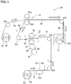
- FIG. 1 is a schematic view for illustrating one embodiment of a printing-lamination inline system of the present invention.
- inkjet printing and lamination are performed in an inline manner, that is, are integrated, and thus manufacturing can be performed on the same line.
- the printing-lamination inline system 60 is a printing-lamination inline system comprising a first web-shaped base material supply unit 64, a single-pass system inkjet printer 10A, an adhesive application unit 70, a second web-shaped base material supply unit 76, a lamination unit 78, and an aging box 72.
- the first web-shaped base material supply unit 64 is configured to supply a first web-shaped base material 12.
- the single-pass system inkjet printer 10A is configured to subject the first web-shaped base material 12 to aqueous inkjet printing.
- the adhesive application unit 70 is configured to apply an adhesive 68 to the first web-shaped base material 12 subjected to the aqueous inkjet printing.
- the second web-shaped base material supply unit 76 is configured to supply a second web-shaped base material 74 so that the second web-shaped base material 74 is bonded to the first web-shaped base material 12.
- the lamination unit 78 is configured to subject the first web-shaped base material 12 and the second web-shaped base material 74 to lamination.
- the aging box 72 is configured to cause aging of a laminate film obtained by the lamination.
- the first web-shaped base material supply unit 64 has the first web-shaped base material 12 wound around a winding roll 80, and the first web-shaped base material 12 is unwound to be supplied to the inkjet printer 10A. There are illustrated feed rolls 82a, 82b, and 82c.
- the first web-shaped base material 12 subjected to printing with an aqueous ink I is fed to the adhesive application unit 70.
- the adhesive application unit 70 comprises a roll 84, a roll 86, and an application roll 88, which form a multi-stage roll, and a pressure roller 90 arranged so as to be opposed to the application roll 88.
- the hot-melt type adhesive 68 is melted by heating and fed to the application roll 88 through the roll 84 and the roll 86 to be thinly applied to a printing surface of the first web-shaped base material 12 passing through between the pressure roller 90.
- the first web-shaped base material 12 having the adhesive 68 applied thereto is bonded to the second web-shaped base material 74 supplied from the second web-shaped base material supply unit 76 by the lamination unit 78 to be subjected to lamination.
- the second web-shaped base material supply unit 76 has the second web-shaped base material 74 wound around a winding roll 94, and the second web-shaped base material 74 is unwound to be supplied to the lamination unit 78 in which press rolls 96a and 96b are arranged.
- the press roll 96a is a heating metal roll
- the press roll 96b is a rubber roll.
- feed rollers 92a and 92b There are illustrated feed rollers 92a and 92b.
- lamination is performed to manufacture a laminate film 98.
- the laminate film 98 is wound around and taken up by a winding roll 100.
- the winding roll 100 is set in the aging box 72, and the inside of the aging box 72 is kept at a temperature of, for example, from about 35°C to about 60°C by the temperature regulating function.
- the manufactured laminate film 98 is stored in the aging box 72 for, for example, about one to two days to cause aging.
- a printing-lamination method using the printing-lamination inline system of the present invention is performed.
- FIG. 2 is a sectional structural view for illustrating one embodiment of the inkjet printer to be used in the printing-lamination inline system of the present invention.
- an inkjet printer 10A is an inkjet printer for an aqueous ink configured to form an image by ejecting an aqueous ink to the first web-shaped base material 12.
- the inkjet printer 10A comprises a conveyance mechanism 14 (conveyance mechanisms 14a and 14b in the illustrated example), inkjet heads 16a to 16e of a single-pass system, and surface pre-heating units 18a to 18e.
- the conveyance mechanism 14 is configured to continuously convey the first web-shaped base material 12.
- the inkjet heads 16a to 16e are configured to eject, by a single-pass system, an aqueous ink to a surface of the first web-shaped base material 12 conveyed by the conveyance mechanism 14.
- the surface pre-heating units 18a to 18e are arranged on an upstream side of conveyance from the inkjet heads 16a to 16e, and are configured to heat at least the surface of the first web-shaped base material 12. Ink ejection by the inkjet heads 16a to 16e is performed with respect to the first web-shaped base material 12 heated by the surface pre-heating units 18a to 18e.
- Surface post-heating units 18b to 18f are arranged on a downstream side of conveyance from the inkjet heads 16a to 16e so that drying of the aqueous ink ejected by the inkjet heads 16a to 16e is further accelerated.
- the surface pre-heating units 18b to 18e also serve as surface post-heating units and hence also function as the surface post-heating units 18b to 18e.
- inkjet heads 16a to 16e various known inkjet ejection devices of the single-pass system can be adopted.
- any known mechanism capable of conveying the first web-shaped base material 12 may be adopted.
- Fig. 2 it is possible to adopt a configuration comprising drive belts 20 and 34, an original roller 22 having the first web-shaped base material 12 wound therearound, various rollers 24, 26, 28, and 30 configured to convey the first web-shaped base material 12, and a take-up roller 32 configured to take up the printed first web-shaped base material 12.
- an operator O who operates the inkjet printer.
- the original roller 22 having the first web-shaped base material 12 wound therearound is placed in a heating box 36 and is heated in advance (pre-heated) to a temperature of from 60°C to 70°C.
- the original roller 22 may be heated in the heating box 36 with hot air or various known heaters. In the illustrated example, the inside of the heating box 36 is heated with hot air.
- the first web-shaped base material 12 heated in advance as described above has at least the surface thereof heated by the surface pre-heating units 18a to 18e arranged on the upstream side of conveyance from the inkjet heads 16a to 16e.
- the hot air blowing means is exemplified.
- hot air at a temperature of from about 40°C to about 80°C, for example, 70°C is blown against the surface of the first web-shaped base material 12.
- a time period for blowing hot air is from about 2 seconds to about 3 seconds when a printing speed is 15 m/min, but is appropriately changed also depending on the temperature of the hot air.
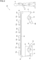
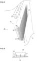
- the hot air blowing means in the embodiment to be used as the surface pre-heating units 18a to 18e is illustrated in FIG. 3 .
- hot air blowing means 42 serving as the surface pre-heating unit 18a it is possible to adopt a configuration comprising a nozzle group main body 50 and a suction mechanism (not shown).
- the nozzle group main body 50 has a plurality of slit-shaped hot air blowing nozzles 46 arranged so as to form gaps 48 with one another.
- the plurality of slit-shaped hot air blowing nozzles 46 each have a slit-shaped hot air outlet port 44 extending in a width direction of the first web-shaped base material 12.
- the suction mechanism is configured to suck an atmosphere of the gaps 48 formed in the nozzle group main body 50.
- the atmosphere of the gaps 48 is sucked in a direction opposite to blowing of hot air H (in a direction opposite to the arrows of FIG. 3 ) by the suction mechanism (not shown).
- various known suction devices can be used, and hence illustration thereof is omitted.
- the effect of reducing color blurring and the like caused by an aqueous ink is attained by sucking the atmosphere of the gaps 48.
- the inkjet heads 16a to 16e are inkjet heads each having an ink storage tank (not shown) of cyan (C), magenta (M), yellow (Y), black (B), or white (W), and the aqueous ink I of each color is ejected from each of the inkjet heads 16a to 16e.
- a back surface heating unit 38 configured to heat the first web-shaped base material 12 from a back surface thereof is arranged.
- a known hot plate can be used.
- an electrothermal heater having a filament laid on a ceramic plate can be used.
- the hot plate is suitably used after being heated to a temperature of, for example, from 40°C to 65°C.
- the back surface heating unit 38 may be arranged across set positions of the inkjet heads 16a to 16e as illustrated in FIG. 2 , or can also be arranged in accordance with set positions of the inkjet heads 16a to 16e.
- the hot air blowing means similar to the surface pre-heating unit 18a can also be used. Further, when the hot air blowing means is used as the back surface heating unit 38, for example, hot air at a temperature of from 40°C to 80°C is suitably blown against the back surface of the first web-shaped base material 12.
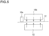
- FIG. 5 there is illustrated an example in which the hot air blowing means is used as the back surface heating unit 38.
- hot air blowing means 52 serving as the back surface heating unit 38.
- the configuration is the same as the above-mentioned configuration except that the hot air blowing means 52 is arranged as the back surface heating unit 38.
- FIG. 6 Another embodiment of an inkjet printer to be used in the printing-lamination inline system of the present invention is illustrated in FIG. 6 .
- FIG. 6 there is illustrated another embodiment of an inkjet printer 10B to be used in the printing-lamination inline system of the present invention.
- the inkjet printer 10B as additional surface post-heating units, laser irradiation devices 40a to 40e are arranged on the downstream side of conveyance from the inkjet heads 16a to 16e.
- the configuration of the inkjet printer 10B is the same as that of the inkjet printer 10A described above except that the laser irradiation devices 40a to 40e are arranged.
- inkjet printers 10A and 10B having the configurations as described above, when ink ejection by the inkjet heads 16a to 16e is performed through use of an aqueous ink with respect to the first web-shaped base material 12 heated by the surface pre-heating units 18a to 18e of the inkjet printers 10A and 10B, printing can be suitably performed with respect to a transparent PET film as the first web-shaped base material without ink flow and color blurring, color mixing during multicolor printing, and the like even at a printing speed of 15 m/min.
- inkjet printers 10A and 10B when the surface post-heating units and the back surface heating unit are combined, ink flow and ink blurring, color mixing during multicolor printing, and the like are further eliminated, and printing can be suitably performed.
- 10A, 10B inkjet printer
- 12 first web-shaped base material
- 14, 14a, 14b conveyance mechanism
- 16a to 16e inkjet head of single-pass system
- 18a to 18e surface pre-heating unit
- 20, 34 drive belt
- 22 original roller
- 24, 26, 28, 30 roller
- 32 take-up roller
- 36 heating box
- 38 heating unit
- 40a to 40e laser irradiation device
- 42, 52 hot air blowing means
- 44 slit-shaped hot air outlet port
- 46 slit-shaped hot air blowing nozzle
- 48 gap
- 50 nozzle group main body
- 60 printing-lamination inline system
- 64 first web-shaped base material supply unit
- 68 adhesive
- 70 adhesive application unit
- 72 aging box
- 74 second web-shaped base material
- 76 second web-shaped base material supply unit
- 78 lamination unit
- 80, 94 100: winding roll
- 82a, 82b
Landscapes
- Health & Medical Sciences (AREA)
- General Health & Medical Sciences (AREA)
- Toxicology (AREA)
- Engineering & Computer Science (AREA)
- Mechanical Engineering (AREA)
- Ink Jet (AREA)
- Coating Apparatus (AREA)
- Ink Jet Recording Methods And Recording Media Thereof (AREA)
- Application Of Or Painting With Fluid Materials (AREA)
- Accessory Devices And Overall Control Thereof (AREA)
Claims (7)
- Inline-Druck-Laminierungssystem (60), umfassend:eine erste Zuführeinheit (64) für bahnförmiges Basismaterial, die dazu konfiguriert ist, ein erstes bahnförmiges Basismaterial zuzuführen,einen Tintenstrahldrucker (10A) eines Single-Pass-Systems, der dazu konfiguriert ist, das erste bahnförmige Basismaterial einem wässrigen Tintenstrahldrucken zu unterziehen;eine Klebstoffauftragseinheit (70), die dazu konfiguriert ist, einen Klebstoff auf das erste bahnförmige Basismaterial aufzubringen, das dem wässrigen Tintenstrahldruck unterzogen wurde;eine zweite Zuführeinheit (76) für bahnförmiges Basismaterial, die dazu konfiguriert ist, ein zweites bahnförmiges Basismaterial so zuzuführen, dass das zweite bahnförmige Basismaterial mit dem ersten bahnförmigen Basismaterial verbunden wird;eine Laminiereinheit (78), die dazu konfiguriert ist, das erste bahnförmige Basismaterial und das zweite bahnförmige Basismaterial einer Laminierung zu unterziehen; undeine Alterungskammer (72), die dazu konfiguriert ist, eine Alterung eines durch die Laminierung erhaltenen Laminatfilms zu bewirken,wobei der Tintenstrahldrucker ein Tintenstrahldrucker für eine wässrige Tinte ist, der dazu konfiguriert ist, ein Bild durch Ausstoßen einer wässrigen Tinte auf das erste bahnförmige Basismaterial zu bilden, wobei der Tintenstrahldrucker umfasst:einen Transportmechanismus (14), der dazu konfiguriert ist, das erste bahnförmige Basismaterial kontinuierlich zu transportieren;einen jeweiligen Tintenstrahlkopf (16a-16e) eines Single-Pass-Systems, der dazu konfiguriert ist, durch ein Single-Pass-System die wässrige Tinte jeweiliger Farben auf eine Oberfläche des ersten bahnförmigen Basismaterials auszustoßen, das durch den Transportmechanismus transportiert wird; undeine jeweilige Oberflächenvorwärmeinheit (18a-18b), die auf einer stromaufwärtigen Seite des Transports von dem jeweiligen Tintenstrahlkopf angeordnet ist und dazu konfiguriert ist, mindestens die Oberfläche des ersten bahnförmigen Basismaterials zu erwärmen,wobei der Tintenstrahldrucker dazu konfiguriert ist, das Bild durch Verwendung des Tintenstrahlkopfs auf dem ersten bahnförmigen Basismaterial zu erzeugen, das durch die Oberflächenvorheizeinheit erwärmt wird, wobei das erste bahnförmige Basismaterial und/oder das zweite bahnförmige Basismaterial einen transparenten Kunstharzfilm umfasst, undwobei die Alterungskammer eine Temperaturregulierungsfunktion aufweist, um die Temperatur in der Kammer auf einer Temperatur von etwa 35 °C bis etwa 60 °C zu halten.
- Inline-Druck-Laminierungssystem nach Anspruch 1, wobei die Laminierung eine lösungsmittelfreie Laminierung ist.
- Inline-Druck-Laminierungssystem nach Anspruch 2, wobei die Oberflächenvorwärmeinheit des Tintenstrahldruckers dazu konfiguriert ist, durch Verwendung einer Heißluftblaseinrichtung zum Blasen heißer Luft gegen die Oberfläche des ersten bahnförmigen Basismaterials zu erwärmen.
- Inline-Druck-Laminierungssystem nach Anspruch 3, wobei die Heißluftblaseinrichtung des Tintenstrahldruckers umfasst:einen Düsengruppenhauptkörper, der eine Vielzahl von schlitzförmigen Heißluftblasdüsen aufweist, die so angeordnet sind, dass sie Lücken miteinander bilden, wobei die Vielzahl von schlitzförmigen Heißluftblasdüsen jeweils eine schlitzförmige Heißluftauslassöffnung aufweisen, die sich in einer Breitenrichtung des ersten bahnförmigen Basismaterials erstreckt; undeinen Saugmechanismus, der dazu konfiguriert ist, eine Atmosphäre der Lücken, die in dem Düsengruppenhauptkörper gebildet sind, anzusaugen.
- Inline-Druck-Laminierungssystem nach einem der Ansprüche 3 oder 4, wobei der Tintenstrahldrucker ferner eine Rückflächen-Heizeinheit umfasst, die dazu konfiguriert ist, eine Rückfläche des ersten bahnförmigen Basismaterials zu erwärmen.
- Inline-Druck-Laminierungssystem nach Anspruch 5, wobei die Rückflächen-Heizeinheit des Tintenstrahldruckers dazu konfiguriert ist, durch Verwendung der Heißluftblaseinrichtung oder einer heißen Platte zu heizen.
- Druck-Laminierungsverfahren unter Verwendung des Inline-Druck-Laminierungssystems (60) nach einem der Ansprüche 1 bis 6,
wobei das Verfahren umfasst:Unterziehen des ersten bahnförmigen Basismaterials einem wässrigen Tintenstrahldrucken durch den Tintenstrahldrucker (10A);Auftragen eines Klebstoffs auf das erste bahnförmige Basismaterial, das dem wässrigen Tintenstrahldrucken unterzogen wurde, durch die Klebstoffauftragseinheit (70) und Verbinden des ersten bahnförmigen Basismaterials und des zweiten bahnförmigen Basismaterials miteinander, um dadurch eine Laminierung durchzuführen; undBewirken einer Alterung eines Laminatfilms, der durch die Laminierung erhalten wird, in der Alterungskammer (72).
Applications Claiming Priority (2)
| Application Number | Priority Date | Filing Date | Title |
|---|---|---|---|
| JP2016077553 | 2016-04-07 | ||
| PCT/JP2017/012531 WO2017175621A1 (ja) | 2016-04-07 | 2017-03-28 | インクジェット印刷ラミネート加工インラインシステム及び方法 |
Publications (3)
| Publication Number | Publication Date |
|---|---|
| EP3441231A1 EP3441231A1 (de) | 2019-02-13 |
| EP3441231A4 EP3441231A4 (de) | 2019-11-27 |
| EP3441231B1 true EP3441231B1 (de) | 2023-02-15 |
Family
ID=60000423
Family Applications (1)
| Application Number | Title | Priority Date | Filing Date |
|---|---|---|---|
| EP17779000.3A Active EP3441231B1 (de) | 2016-04-07 | 2017-03-28 | Inline-system und -verfahren für tintenstrahldrucklaminierung |
Country Status (7)
| Country | Link |
|---|---|
| US (1) | US10744794B2 (de) |
| EP (1) | EP3441231B1 (de) |
| JP (1) | JP6619504B2 (de) |
| CN (1) | CN108883646B (de) |
| ES (1) | ES2939382T3 (de) |
| TW (1) | TWI794166B (de) |
| WO (1) | WO2017175621A1 (de) |
Cited By (1)
| Publication number | Priority date | Publication date | Assignee | Title |
|---|---|---|---|---|
| US12391030B2 (en) | 2023-04-28 | 2025-08-19 | ACCO Brands Corporation | High-speed in-line cold laminating unit |
Families Citing this family (14)
| Publication number | Priority date | Publication date | Assignee | Title |
|---|---|---|---|---|
| JP6979202B2 (ja) * | 2017-12-06 | 2021-12-08 | 富士機械工業株式会社 | ラミネート装置、ラミネート製品製造装置及びラミネート製品の製造方法 |
| JP6821874B2 (ja) * | 2019-03-13 | 2021-01-27 | 東洋インキScホールディングス株式会社 | 積層体及びその製造方法 |
| WO2022003336A1 (en) | 2020-06-30 | 2022-01-06 | Sun Chemical Corporation | Lamination primers and inks for aqueous inkjet printing |
| JP7536401B2 (ja) * | 2020-09-11 | 2024-08-20 | artience株式会社 | 積層体の製造方法 |
| CN112024271A (zh) * | 2020-09-29 | 2020-12-04 | 世星科技股份有限公司 | 一种自动调节的涂布装置 |
| EP3984741B1 (de) * | 2020-10-16 | 2025-09-17 | Jesús Francisco Barberan Latorre | System zur herstellung eines substrats mit dekorativem design |
| EP4063143A1 (de) * | 2021-03-26 | 2022-09-28 | Jesús Francisco Barberan Latorre | Verfahren und system zur herstellung eines reliefs auf einem substrat |
| JP7678978B2 (ja) * | 2021-05-17 | 2025-05-19 | 大日本印刷株式会社 | プリンタシステム |
| GB2617583B (en) * | 2022-04-13 | 2024-09-11 | Printaply Ltd | Film forming apparatus |
| GB2617584B (en) * | 2022-04-13 | 2024-09-11 | Printaply Ltd | Film forming apparatus |
| CN115301474B (zh) * | 2022-08-13 | 2024-03-01 | 福建壹工软包装科技有限公司 | 一种渐变梯度光学功能膜制备装置及制备方法 |
| EP4349607A1 (de) * | 2022-10-03 | 2024-04-10 | Tetra Laval Holdings & Finance S.A. | Verfahren und vorrichtung zur herstellung einer laminierten verpackungsmaterialbahn |
| US20260042300A1 (en) * | 2022-10-03 | 2026-02-12 | Tetra Laval Holdings & Finance S.A. | Method for manufacturing a laminated packaging material web |
| CN120129610A (zh) * | 2022-10-28 | 2025-06-10 | 利乐拉瓦尔集团及财务有限公司 | 用于制造层压包装材料卷材的方法和单元 |
Citations (1)
| Publication number | Priority date | Publication date | Assignee | Title |
|---|---|---|---|---|
| EP2857462A1 (de) * | 2012-05-30 | 2015-04-08 | DIC Corporation | Wässrige tinte für tintenstrahlaufzeichnung und herstellungsverfahren für ein laminat |
Family Cites Families (35)
| Publication number | Priority date | Publication date | Assignee | Title |
|---|---|---|---|---|
| US3130113A (en) * | 1954-08-09 | 1964-04-21 | United Merchants & Mfg | Self-adhesive decorative surface covering material |
| DE3315139A1 (de) | 1982-04-28 | 1983-11-03 | Canon K.K., Tokyo | Aufzeichnungsgeraet |
| JPS58224778A (ja) * | 1982-06-23 | 1983-12-27 | Canon Inc | 記録装置 |
| JP3023930B2 (ja) * | 1991-03-13 | 2000-03-21 | 大日本印刷株式会社 | 転写箔およびそれを使用したツヤ消し面または塗装面の形成方法 |
| JPH0511516A (ja) * | 1991-07-03 | 1993-01-22 | Mitsubishi Paper Mills Ltd | 電子写真平版印刷原版 |
| US5989381A (en) * | 1992-07-30 | 1999-11-23 | C.I. Kasei Co., Ltd. | Method for adhesive bonding of an overlay film to an acrylic resin board |
| US5896154A (en) * | 1993-04-16 | 1999-04-20 | Hitachi Koki Co., Ltd. | Ink jet printer |
| JPH0940008A (ja) | 1995-07-21 | 1997-02-10 | Toppan Printing Co Ltd | 密封包装袋 |
| JP4620817B2 (ja) | 1998-05-29 | 2011-01-26 | キヤノン株式会社 | 画像処理装置および画像処理方法 |
| EP1287982A4 (de) | 2000-05-26 | 2004-10-27 | Kureha Chemical Ind Co Ltd | Feuchtigkeitsunempfindlicher mehrschichtiger film |
| JP2002052850A (ja) * | 2000-08-14 | 2002-02-19 | Toppan Printing Co Ltd | 環境配慮型高光沢印刷物の製造方法 |
| CN1286936C (zh) * | 2001-06-21 | 2006-11-29 | 日本聚氨酯工业株式会社 | 非水系层压粘合剂 |
| JP4433153B2 (ja) * | 2003-12-03 | 2010-03-17 | 三菱瓦斯化学株式会社 | ラミネートフィルムの製造方法 |
| JP2006248173A (ja) * | 2005-03-14 | 2006-09-21 | Fuji Photo Film Co Ltd | 画像記録装置 |
| KR101077510B1 (ko) | 2008-06-20 | 2011-10-27 | 김성수 | 자동스크린 롤 전사인쇄방법과 인쇄된 전사용지의 제품 |
| JP5212073B2 (ja) | 2008-12-16 | 2013-06-19 | コニカミノルタホールディングス株式会社 | インクジェット記録方法 |
| ATE516964T1 (de) | 2008-12-16 | 2011-08-15 | Konica Minolta Holdings Inc | Bilderzeugungsverfahren |
| US8096719B1 (en) * | 2009-04-21 | 2012-01-17 | Plastic Cards, LLC | Continuous personalized plastic card manufacturing system |
| CN101997038A (zh) * | 2009-08-19 | 2011-03-30 | 南京纳泉高科材料股份有限公司 | 一种太阳能电池背板膜及其制备方法 |
| US8579406B2 (en) | 2009-09-16 | 2013-11-12 | Xerox Corporation | Real time bleed-though detection for continuous web printers |
| DE102009056761A1 (de) * | 2009-12-03 | 2011-06-09 | Steinemann Technology Ag | Verfahren zur Herstellung von Druckprodukten |
| US8596777B2 (en) * | 2010-04-30 | 2013-12-03 | Seiko Epson Corporation | Liquid ejecting apparatus |
| JP5709587B2 (ja) * | 2011-03-03 | 2015-04-30 | 大和グラビヤ株式会社 | エージングボックス |
| CN202071500U (zh) | 2011-03-11 | 2011-12-14 | 潍坊胜达塑胶有限公司 | 薄膜印刷复合一体机 |
| JP2013001755A (ja) | 2011-06-14 | 2013-01-07 | Dic Corp | ラミネート加工用水性インクジェット記録用インク及び積層体の製造方法 |
| JP5447878B2 (ja) * | 2011-06-16 | 2014-03-19 | 大日本印刷株式会社 | ラミネート装置 |
| WO2013008691A1 (ja) | 2011-07-12 | 2013-01-17 | Dic株式会社 | 水性インクジェット記録用白色インク、白色顔料ペースト、インクジェット記録用水性インクセット |
| US9248666B2 (en) | 2012-02-14 | 2016-02-02 | Ricoh Company, Ltd. | Drying apparatus and printing apparatus |
| JP6101968B2 (ja) * | 2012-03-16 | 2017-03-29 | 株式会社ミマキエンジニアリング | インクジェット記録装置 |
| EP2644391B1 (de) | 2012-03-30 | 2016-05-11 | Tarkett GDL S.A. | Vorrichtung zum Drucken, entsprechendes Verfahren und gedrucktes Produkt |
| JP6089919B2 (ja) | 2013-04-22 | 2017-03-08 | 東洋インキScホールディングス株式会社 | 水性インクジェットインク |
| JP6225490B2 (ja) * | 2013-05-31 | 2017-11-08 | 大日本印刷株式会社 | 医薬品包装体 |
| US9492336B2 (en) | 2013-10-18 | 2016-11-15 | The Procter & Gamble Company | Absorbent article having a composite web with visual signal thereon |
| JP6246686B2 (ja) | 2014-09-16 | 2017-12-13 | 富士フイルム株式会社 | インクジェット記録方法 |
| CN104946155A (zh) * | 2015-06-10 | 2015-09-30 | 田义松 | 一种不干胶贴膜生产流程 |
-
2017
- 2017-03-28 WO PCT/JP2017/012531 patent/WO2017175621A1/ja not_active Ceased
- 2017-03-28 US US16/085,190 patent/US10744794B2/en active Active
- 2017-03-28 ES ES17779000T patent/ES2939382T3/es active Active
- 2017-03-28 CN CN201780016114.7A patent/CN108883646B/zh active Active
- 2017-03-28 EP EP17779000.3A patent/EP3441231B1/de active Active
- 2017-03-28 JP JP2018510547A patent/JP6619504B2/ja active Active
- 2017-04-06 TW TW106111563A patent/TWI794166B/zh active
Patent Citations (1)
| Publication number | Priority date | Publication date | Assignee | Title |
|---|---|---|---|---|
| EP2857462A1 (de) * | 2012-05-30 | 2015-04-08 | DIC Corporation | Wässrige tinte für tintenstrahlaufzeichnung und herstellungsverfahren für ein laminat |
Cited By (1)
| Publication number | Priority date | Publication date | Assignee | Title |
|---|---|---|---|---|
| US12391030B2 (en) | 2023-04-28 | 2025-08-19 | ACCO Brands Corporation | High-speed in-line cold laminating unit |
Also Published As
| Publication number | Publication date |
|---|---|
| WO2017175621A1 (ja) | 2017-10-12 |
| TWI794166B (zh) | 2023-03-01 |
| CN108883646B (zh) | 2020-10-30 |
| US10744794B2 (en) | 2020-08-18 |
| CN108883646A (zh) | 2018-11-23 |
| EP3441231A4 (de) | 2019-11-27 |
| JPWO2017175621A1 (ja) | 2019-02-28 |
| EP3441231A1 (de) | 2019-02-13 |
| JP6619504B2 (ja) | 2019-12-11 |
| ES2939382T3 (es) | 2023-04-21 |
| TW201803947A (zh) | 2018-02-01 |
| US20190084321A1 (en) | 2019-03-21 |
Similar Documents
| Publication | Publication Date | Title |
|---|---|---|
| EP3441231B1 (de) | Inline-system und -verfahren für tintenstrahldrucklaminierung | |
| EP3441230B1 (de) | Inline-system und -verfahren für tintenstrahldrucklaminierung | |
| US12122148B2 (en) | Inkjet printer and inkjet printing method using the same | |
| JP6440924B1 (ja) | インクジェットプリンタ及びそれを用いたインクジェット印刷方法 | |
| JP7029197B2 (ja) | インクジェットプリンタ及びインクジェット印刷方法 | |
| JP2020082570A (ja) | 記録媒体加熱装置、液体吐出装置 | |
| JP6641890B2 (ja) | 印刷装置および印刷方法 |
Legal Events
| Date | Code | Title | Description |
|---|---|---|---|
| STAA | Information on the status of an ep patent application or granted ep patent |
Free format text: STATUS: THE INTERNATIONAL PUBLICATION HAS BEEN MADE |
|
| PUAI | Public reference made under article 153(3) epc to a published international application that has entered the european phase |
Free format text: ORIGINAL CODE: 0009012 |
|
| STAA | Information on the status of an ep patent application or granted ep patent |
Free format text: STATUS: REQUEST FOR EXAMINATION WAS MADE |
|
| 17P | Request for examination filed |
Effective date: 20180904 |
|
| AK | Designated contracting states |
Kind code of ref document: A1 Designated state(s): AL AT BE BG CH CY CZ DE DK EE ES FI FR GB GR HR HU IE IS IT LI LT LU LV MC MK MT NL NO PL PT RO RS SE SI SK SM TR |
|
| AX | Request for extension of the european patent |
Extension state: BA ME |
|
| DAV | Request for validation of the european patent (deleted) | ||
| DAX | Request for extension of the european patent (deleted) | ||
| A4 | Supplementary search report drawn up and despatched |
Effective date: 20191024 |
|
| RIC1 | Information provided on ipc code assigned before grant |
Ipc: B41J 29/00 20060101AFI20191018BHEP Ipc: B32B 37/12 20060101ALI20191018BHEP Ipc: B41M 5/00 20060101ALI20191018BHEP Ipc: B41M 7/00 20060101ALI20191018BHEP Ipc: B05C 13/02 20060101ALI20191018BHEP Ipc: B29C 65/48 20060101ALI20191018BHEP Ipc: B32B 37/00 20060101ALI20191018BHEP Ipc: B29C 65/52 20060101ALI20191018BHEP Ipc: B41J 11/00 20060101ALI20191018BHEP Ipc: B41J 2/01 20060101ALI20191018BHEP Ipc: B05C 9/14 20060101ALI20191018BHEP Ipc: B32B 38/00 20060101ALI20191018BHEP Ipc: B41J 15/18 20060101ALI20191018BHEP |
|
| STAA | Information on the status of an ep patent application or granted ep patent |
Free format text: STATUS: EXAMINATION IS IN PROGRESS |
|
| 17Q | First examination report despatched |
Effective date: 20220321 |
|
| GRAP | Despatch of communication of intention to grant a patent |
Free format text: ORIGINAL CODE: EPIDOSNIGR1 |
|
| STAA | Information on the status of an ep patent application or granted ep patent |
Free format text: STATUS: GRANT OF PATENT IS INTENDED |
|
| INTG | Intention to grant announced |
Effective date: 20221025 |
|
| GRAS | Grant fee paid |
Free format text: ORIGINAL CODE: EPIDOSNIGR3 |
|
| GRAA | (expected) grant |
Free format text: ORIGINAL CODE: 0009210 |
|
| STAA | Information on the status of an ep patent application or granted ep patent |
Free format text: STATUS: THE PATENT HAS BEEN GRANTED |
|
| AK | Designated contracting states |
Kind code of ref document: B1 Designated state(s): AL AT BE BG CH CY CZ DE DK EE ES FI FR GB GR HR HU IE IS IT LI LT LU LV MC MK MT NL NO PL PT RO RS SE SI SK SM TR |
|
| REG | Reference to a national code |
Ref country code: CH Ref legal event code: EP Ref country code: GB Ref legal event code: FG4D |
|
| REG | Reference to a national code |
Ref country code: DE Ref legal event code: R096 Ref document number: 602017066050 Country of ref document: DE |
|
| REG | Reference to a national code |
Ref country code: AT Ref legal event code: REF Ref document number: 1548051 Country of ref document: AT Kind code of ref document: T Effective date: 20230315 Ref country code: IE Ref legal event code: FG4D |
|
| REG | Reference to a national code |
Ref country code: ES Ref legal event code: FG2A Ref document number: 2939382 Country of ref document: ES Kind code of ref document: T3 Effective date: 20230421 |
|
| REG | Reference to a national code |
Ref country code: LT Ref legal event code: MG9D |
|
| REG | Reference to a national code |
Ref country code: NL Ref legal event code: MP Effective date: 20230215 |
|
| REG | Reference to a national code |
Ref country code: AT Ref legal event code: MK05 Ref document number: 1548051 Country of ref document: AT Kind code of ref document: T Effective date: 20230215 |
|
| PG25 | Lapsed in a contracting state [announced via postgrant information from national office to epo] |
Ref country code: RS Free format text: LAPSE BECAUSE OF FAILURE TO SUBMIT A TRANSLATION OF THE DESCRIPTION OR TO PAY THE FEE WITHIN THE PRESCRIBED TIME-LIMIT Effective date: 20230215 Ref country code: PT Free format text: LAPSE BECAUSE OF FAILURE TO SUBMIT A TRANSLATION OF THE DESCRIPTION OR TO PAY THE FEE WITHIN THE PRESCRIBED TIME-LIMIT Effective date: 20230615 Ref country code: NO Free format text: LAPSE BECAUSE OF FAILURE TO SUBMIT A TRANSLATION OF THE DESCRIPTION OR TO PAY THE FEE WITHIN THE PRESCRIBED TIME-LIMIT Effective date: 20230515 Ref country code: NL Free format text: LAPSE BECAUSE OF FAILURE TO SUBMIT A TRANSLATION OF THE DESCRIPTION OR TO PAY THE FEE WITHIN THE PRESCRIBED TIME-LIMIT Effective date: 20230215 Ref country code: LV Free format text: LAPSE BECAUSE OF FAILURE TO SUBMIT A TRANSLATION OF THE DESCRIPTION OR TO PAY THE FEE WITHIN THE PRESCRIBED TIME-LIMIT Effective date: 20230215 Ref country code: LT Free format text: LAPSE BECAUSE OF FAILURE TO SUBMIT A TRANSLATION OF THE DESCRIPTION OR TO PAY THE FEE WITHIN THE PRESCRIBED TIME-LIMIT Effective date: 20230215 Ref country code: HR Free format text: LAPSE BECAUSE OF FAILURE TO SUBMIT A TRANSLATION OF THE DESCRIPTION OR TO PAY THE FEE WITHIN THE PRESCRIBED TIME-LIMIT Effective date: 20230215 Ref country code: AT Free format text: LAPSE BECAUSE OF FAILURE TO SUBMIT A TRANSLATION OF THE DESCRIPTION OR TO PAY THE FEE WITHIN THE PRESCRIBED TIME-LIMIT Effective date: 20230215 |
|
| PG25 | Lapsed in a contracting state [announced via postgrant information from national office to epo] |
Ref country code: SE Free format text: LAPSE BECAUSE OF FAILURE TO SUBMIT A TRANSLATION OF THE DESCRIPTION OR TO PAY THE FEE WITHIN THE PRESCRIBED TIME-LIMIT Effective date: 20230215 Ref country code: PL Free format text: LAPSE BECAUSE OF FAILURE TO SUBMIT A TRANSLATION OF THE DESCRIPTION OR TO PAY THE FEE WITHIN THE PRESCRIBED TIME-LIMIT Effective date: 20230215 Ref country code: IS Free format text: LAPSE BECAUSE OF FAILURE TO SUBMIT A TRANSLATION OF THE DESCRIPTION OR TO PAY THE FEE WITHIN THE PRESCRIBED TIME-LIMIT Effective date: 20230615 Ref country code: GR Free format text: LAPSE BECAUSE OF FAILURE TO SUBMIT A TRANSLATION OF THE DESCRIPTION OR TO PAY THE FEE WITHIN THE PRESCRIBED TIME-LIMIT Effective date: 20230516 Ref country code: FI Free format text: LAPSE BECAUSE OF FAILURE TO SUBMIT A TRANSLATION OF THE DESCRIPTION OR TO PAY THE FEE WITHIN THE PRESCRIBED TIME-LIMIT Effective date: 20230215 |
|
| PG25 | Lapsed in a contracting state [announced via postgrant information from national office to epo] |
Ref country code: SM Free format text: LAPSE BECAUSE OF FAILURE TO SUBMIT A TRANSLATION OF THE DESCRIPTION OR TO PAY THE FEE WITHIN THE PRESCRIBED TIME-LIMIT Effective date: 20230215 Ref country code: RO Free format text: LAPSE BECAUSE OF FAILURE TO SUBMIT A TRANSLATION OF THE DESCRIPTION OR TO PAY THE FEE WITHIN THE PRESCRIBED TIME-LIMIT Effective date: 20230215 Ref country code: EE Free format text: LAPSE BECAUSE OF FAILURE TO SUBMIT A TRANSLATION OF THE DESCRIPTION OR TO PAY THE FEE WITHIN THE PRESCRIBED TIME-LIMIT Effective date: 20230215 Ref country code: DK Free format text: LAPSE BECAUSE OF FAILURE TO SUBMIT A TRANSLATION OF THE DESCRIPTION OR TO PAY THE FEE WITHIN THE PRESCRIBED TIME-LIMIT Effective date: 20230215 Ref country code: CZ Free format text: LAPSE BECAUSE OF FAILURE TO SUBMIT A TRANSLATION OF THE DESCRIPTION OR TO PAY THE FEE WITHIN THE PRESCRIBED TIME-LIMIT Effective date: 20230215 |
|
| REG | Reference to a national code |
Ref country code: DE Ref legal event code: R097 Ref document number: 602017066050 Country of ref document: DE |
|
| PG25 | Lapsed in a contracting state [announced via postgrant information from national office to epo] |
Ref country code: SK Free format text: LAPSE BECAUSE OF FAILURE TO SUBMIT A TRANSLATION OF THE DESCRIPTION OR TO PAY THE FEE WITHIN THE PRESCRIBED TIME-LIMIT Effective date: 20230215 |
|
| PLBE | No opposition filed within time limit |
Free format text: ORIGINAL CODE: 0009261 |
|
| STAA | Information on the status of an ep patent application or granted ep patent |
Free format text: STATUS: NO OPPOSITION FILED WITHIN TIME LIMIT |
|
| PG25 | Lapsed in a contracting state [announced via postgrant information from national office to epo] |
Ref country code: LU Free format text: LAPSE BECAUSE OF NON-PAYMENT OF DUE FEES Effective date: 20230328 |
|
| PG25 | Lapsed in a contracting state [announced via postgrant information from national office to epo] |
Ref country code: MC Free format text: LAPSE BECAUSE OF FAILURE TO SUBMIT A TRANSLATION OF THE DESCRIPTION OR TO PAY THE FEE WITHIN THE PRESCRIBED TIME-LIMIT Effective date: 20230215 |
|
| REG | Reference to a national code |
Ref country code: IE Ref legal event code: MM4A |
|
| 26N | No opposition filed |
Effective date: 20231116 |
|
| PG25 | Lapsed in a contracting state [announced via postgrant information from national office to epo] |
Ref country code: SI Free format text: LAPSE BECAUSE OF FAILURE TO SUBMIT A TRANSLATION OF THE DESCRIPTION OR TO PAY THE FEE WITHIN THE PRESCRIBED TIME-LIMIT Effective date: 20230215 Ref country code: MC Free format text: LAPSE BECAUSE OF FAILURE TO SUBMIT A TRANSLATION OF THE DESCRIPTION OR TO PAY THE FEE WITHIN THE PRESCRIBED TIME-LIMIT Effective date: 20230215 Ref country code: IE Free format text: LAPSE BECAUSE OF NON-PAYMENT OF DUE FEES Effective date: 20230328 |
|
| PG25 | Lapsed in a contracting state [announced via postgrant information from national office to epo] |
Ref country code: BG Free format text: LAPSE BECAUSE OF FAILURE TO SUBMIT A TRANSLATION OF THE DESCRIPTION OR TO PAY THE FEE WITHIN THE PRESCRIBED TIME-LIMIT Effective date: 20230215 |
|
| PG25 | Lapsed in a contracting state [announced via postgrant information from national office to epo] |
Ref country code: BG Free format text: LAPSE BECAUSE OF FAILURE TO SUBMIT A TRANSLATION OF THE DESCRIPTION OR TO PAY THE FEE WITHIN THE PRESCRIBED TIME-LIMIT Effective date: 20230215 |
|
| PGFP | Annual fee paid to national office [announced via postgrant information from national office to epo] |
Ref country code: ES Payment date: 20250429 Year of fee payment: 9 |
|
| PGFP | Annual fee paid to national office [announced via postgrant information from national office to epo] |
Ref country code: CH Payment date: 20250401 Year of fee payment: 9 |
|
| PG25 | Lapsed in a contracting state [announced via postgrant information from national office to epo] |
Ref country code: CY Free format text: LAPSE BECAUSE OF FAILURE TO SUBMIT A TRANSLATION OF THE DESCRIPTION OR TO PAY THE FEE WITHIN THE PRESCRIBED TIME-LIMIT; INVALID AB INITIO Effective date: 20170328 |
|
| PG25 | Lapsed in a contracting state [announced via postgrant information from national office to epo] |
Ref country code: HU Free format text: LAPSE BECAUSE OF FAILURE TO SUBMIT A TRANSLATION OF THE DESCRIPTION OR TO PAY THE FEE WITHIN THE PRESCRIBED TIME-LIMIT; INVALID AB INITIO Effective date: 20170328 |
|
| REG | Reference to a national code |
Ref country code: CH Ref legal event code: U11 Free format text: ST27 STATUS EVENT CODE: U-0-0-U10-U11 (AS PROVIDED BY THE NATIONAL OFFICE) Effective date: 20260401 |
|
| PGFP | Annual fee paid to national office [announced via postgrant information from national office to epo] |
Ref country code: GB Payment date: 20260324 Year of fee payment: 10 |
|
| PGFP | Annual fee paid to national office [announced via postgrant information from national office to epo] |
Ref country code: DE Payment date: 20260319 Year of fee payment: 10 |
|
| PGFP | Annual fee paid to national office [announced via postgrant information from national office to epo] |
Ref country code: BE Payment date: 20260319 Year of fee payment: 10 Ref country code: IT Payment date: 20260324 Year of fee payment: 10 |
|
| PGFP | Annual fee paid to national office [announced via postgrant information from national office to epo] |
Ref country code: FR Payment date: 20260320 Year of fee payment: 10 |
|
| PGFP | Annual fee paid to national office [announced via postgrant information from national office to epo] |
Ref country code: TR Payment date: 20260325 Year of fee payment: 10 |