EP3441029B1 - Implantat für oberschenkelhalsbruch - Google Patents
Implantat für oberschenkelhalsbruch Download PDFInfo
- Publication number
- EP3441029B1 EP3441029B1 EP18198320.6A EP18198320A EP3441029B1 EP 3441029 B1 EP3441029 B1 EP 3441029B1 EP 18198320 A EP18198320 A EP 18198320A EP 3441029 B1 EP3441029 B1 EP 3441029B1
- Authority
- EP
- European Patent Office
- Prior art keywords
- bone
- opening
- implant shaft
- shaft
- bone fixation
- Prior art date
- Legal status (The legal status is an assumption and is not a legal conclusion. Google has not performed a legal analysis and makes no representation as to the accuracy of the status listed.)
- Active
Links
- 239000007943 implant Substances 0.000 title claims description 167
- 208000020089 femoral neck fracture Diseases 0.000 title description 10
- 210000000988 bone and bone Anatomy 0.000 claims description 274
- 238000003780 insertion Methods 0.000 claims description 60
- 230000037431 insertion Effects 0.000 claims description 60
- 238000002513 implantation Methods 0.000 claims description 5
- 238000000034 method Methods 0.000 description 27
- 238000005553 drilling Methods 0.000 description 15
- 230000007246 mechanism Effects 0.000 description 15
- 210000000689 upper leg Anatomy 0.000 description 12
- 210000002436 femur neck Anatomy 0.000 description 8
- 206010017076 Fracture Diseases 0.000 description 4
- 230000005012 migration Effects 0.000 description 4
- 238000013508 migration Methods 0.000 description 4
- 208000010392 Bone Fractures Diseases 0.000 description 3
- 230000035876 healing Effects 0.000 description 3
- 230000004075 alteration Effects 0.000 description 2
- 210000003484 anatomy Anatomy 0.000 description 2
- 230000006835 compression Effects 0.000 description 2
- 238000007906 compression Methods 0.000 description 2
- 210000000501 femur body Anatomy 0.000 description 2
- 238000001746 injection moulding Methods 0.000 description 2
- 238000004806 packaging method and process Methods 0.000 description 2
- 230000002980 postoperative effect Effects 0.000 description 2
- 210000004872 soft tissue Anatomy 0.000 description 2
- 210000005065 subchondral bone plate Anatomy 0.000 description 2
- OKTJSMMVPCPJKN-UHFFFAOYSA-N Carbon Chemical compound [C] OKTJSMMVPCPJKN-UHFFFAOYSA-N 0.000 description 1
- 206010020100 Hip fracture Diseases 0.000 description 1
- 208000006670 Multiple fractures Diseases 0.000 description 1
- 208000006735 Periostitis Diseases 0.000 description 1
- 230000000712 assembly Effects 0.000 description 1
- 238000000429 assembly Methods 0.000 description 1
- 230000004323 axial length Effects 0.000 description 1
- 229910052799 carbon Inorganic materials 0.000 description 1
- 230000001419 dependent effect Effects 0.000 description 1
- 210000000527 greater trochanter Anatomy 0.000 description 1
- 210000004394 hip joint Anatomy 0.000 description 1
- 230000003116 impacting effect Effects 0.000 description 1
- 230000036512 infertility Effects 0.000 description 1
- 238000012966 insertion method Methods 0.000 description 1
- 238000007918 intramuscular administration Methods 0.000 description 1
- 230000007794 irritation Effects 0.000 description 1
- 230000014759 maintenance of location Effects 0.000 description 1
- 239000000463 material Substances 0.000 description 1
- 239000012528 membrane Substances 0.000 description 1
- 239000002184 metal Substances 0.000 description 1
- 238000012986 modification Methods 0.000 description 1
- 230000004048 modification Effects 0.000 description 1
- 210000003205 muscle Anatomy 0.000 description 1
- 238000010883 osseointegration Methods 0.000 description 1
- 230000035515 penetration Effects 0.000 description 1
- 210000003460 periosteum Anatomy 0.000 description 1
- 230000002265 prevention Effects 0.000 description 1
- 210000003314 quadriceps muscle Anatomy 0.000 description 1
- 230000000087 stabilizing effect Effects 0.000 description 1
- 238000006467 substitution reaction Methods 0.000 description 1
- 238000001356 surgical procedure Methods 0.000 description 1
- 238000003786 synthesis reaction Methods 0.000 description 1
- ZIBGPFATKBEMQZ-UHFFFAOYSA-N triethylene glycol Chemical compound OCCOCCOCCO ZIBGPFATKBEMQZ-UHFFFAOYSA-N 0.000 description 1
Images


Classifications
-
- A—HUMAN NECESSITIES
- A61—MEDICAL OR VETERINARY SCIENCE; HYGIENE
- A61B—DIAGNOSIS; SURGERY; IDENTIFICATION
- A61B17/00—Surgical instruments, devices or methods, e.g. tourniquets
- A61B17/56—Surgical instruments or methods for treatment of bones or joints; Devices specially adapted therefor
- A61B17/58—Surgical instruments or methods for treatment of bones or joints; Devices specially adapted therefor for osteosynthesis, e.g. bone plates, screws, setting implements or the like
- A61B17/68—Internal fixation devices, including fasteners and spinal fixators, even if a part thereof projects from the skin
- A61B17/74—Devices for the head or neck or trochanter of the femur
- A61B17/742—Devices for the head or neck or trochanter of the femur having one or more longitudinal elements oriented along or parallel to the axis of the neck
- A61B17/746—Devices for the head or neck or trochanter of the femur having one or more longitudinal elements oriented along or parallel to the axis of the neck the longitudinal elements coupled to a plate opposite the femoral head
-
- A—HUMAN NECESSITIES
- A61—MEDICAL OR VETERINARY SCIENCE; HYGIENE
- A61B—DIAGNOSIS; SURGERY; IDENTIFICATION
- A61B17/00—Surgical instruments, devices or methods, e.g. tourniquets
- A61B17/16—Bone cutting, breaking or removal means other than saws, e.g. Osteoclasts; Drills or chisels for bones; Trepans
- A61B17/17—Guides or aligning means for drills, mills, pins or wires
- A61B17/1721—Guides or aligning means for drills, mills, pins or wires for applying pins along or parallel to the axis of the femoral neck
-
- A—HUMAN NECESSITIES
- A61—MEDICAL OR VETERINARY SCIENCE; HYGIENE
- A61B—DIAGNOSIS; SURGERY; IDENTIFICATION
- A61B17/00—Surgical instruments, devices or methods, e.g. tourniquets
- A61B17/56—Surgical instruments or methods for treatment of bones or joints; Devices specially adapted therefor
- A61B17/58—Surgical instruments or methods for treatment of bones or joints; Devices specially adapted therefor for osteosynthesis, e.g. bone plates, screws, setting implements or the like
- A61B17/68—Internal fixation devices, including fasteners and spinal fixators, even if a part thereof projects from the skin
- A61B17/80—Cortical plates, i.e. bone plates; Instruments for holding or positioning cortical plates, or for compressing bones attached to cortical plates
- A61B17/8052—Cortical plates, i.e. bone plates; Instruments for holding or positioning cortical plates, or for compressing bones attached to cortical plates immobilised relative to screws by interlocking form of the heads and plate holes, e.g. conical or threaded
- A61B17/8057—Cortical plates, i.e. bone plates; Instruments for holding or positioning cortical plates, or for compressing bones attached to cortical plates immobilised relative to screws by interlocking form of the heads and plate holes, e.g. conical or threaded the interlocking form comprising a thread
-
- A—HUMAN NECESSITIES
- A61—MEDICAL OR VETERINARY SCIENCE; HYGIENE
- A61B—DIAGNOSIS; SURGERY; IDENTIFICATION
- A61B17/00—Surgical instruments, devices or methods, e.g. tourniquets
- A61B17/56—Surgical instruments or methods for treatment of bones or joints; Devices specially adapted therefor
- A61B17/58—Surgical instruments or methods for treatment of bones or joints; Devices specially adapted therefor for osteosynthesis, e.g. bone plates, screws, setting implements or the like
- A61B17/68—Internal fixation devices, including fasteners and spinal fixators, even if a part thereof projects from the skin
- A61B17/84—Fasteners therefor or fasteners being internal fixation devices
- A61B17/86—Pins or screws or threaded wires; nuts therefor
- A61B17/8605—Heads, i.e. proximal ends projecting from bone
-
- A—HUMAN NECESSITIES
- A61—MEDICAL OR VETERINARY SCIENCE; HYGIENE
- A61B—DIAGNOSIS; SURGERY; IDENTIFICATION
- A61B17/00—Surgical instruments, devices or methods, e.g. tourniquets
- A61B17/56—Surgical instruments or methods for treatment of bones or joints; Devices specially adapted therefor
- A61B17/58—Surgical instruments or methods for treatment of bones or joints; Devices specially adapted therefor for osteosynthesis, e.g. bone plates, screws, setting implements or the like
- A61B17/68—Internal fixation devices, including fasteners and spinal fixators, even if a part thereof projects from the skin
- A61B17/84—Fasteners therefor or fasteners being internal fixation devices
- A61B17/86—Pins or screws or threaded wires; nuts therefor
- A61B17/8625—Shanks, i.e. parts contacting bone tissue
- A61B17/863—Shanks, i.e. parts contacting bone tissue with thread interrupted or changing its form along shank, other than constant taper
-
- A—HUMAN NECESSITIES
- A61—MEDICAL OR VETERINARY SCIENCE; HYGIENE
- A61B—DIAGNOSIS; SURGERY; IDENTIFICATION
- A61B17/00—Surgical instruments, devices or methods, e.g. tourniquets
- A61B17/56—Surgical instruments or methods for treatment of bones or joints; Devices specially adapted therefor
- A61B17/58—Surgical instruments or methods for treatment of bones or joints; Devices specially adapted therefor for osteosynthesis, e.g. bone plates, screws, setting implements or the like
- A61B17/68—Internal fixation devices, including fasteners and spinal fixators, even if a part thereof projects from the skin
- A61B17/84—Fasteners therefor or fasteners being internal fixation devices
- A61B17/86—Pins or screws or threaded wires; nuts therefor
- A61B17/8685—Pins or screws or threaded wires; nuts therefor comprising multiple separate parts
-
- A—HUMAN NECESSITIES
- A61—MEDICAL OR VETERINARY SCIENCE; HYGIENE
- A61B—DIAGNOSIS; SURGERY; IDENTIFICATION
- A61B17/00—Surgical instruments, devices or methods, e.g. tourniquets
- A61B17/56—Surgical instruments or methods for treatment of bones or joints; Devices specially adapted therefor
- A61B17/58—Surgical instruments or methods for treatment of bones or joints; Devices specially adapted therefor for osteosynthesis, e.g. bone plates, screws, setting implements or the like
- A61B17/88—Osteosynthesis instruments; Methods or means for implanting or extracting internal or external fixation devices
- A61B17/90—Guides therefor
-
- A—HUMAN NECESSITIES
- A61—MEDICAL OR VETERINARY SCIENCE; HYGIENE
- A61B—DIAGNOSIS; SURGERY; IDENTIFICATION
- A61B17/00—Surgical instruments, devices or methods, e.g. tourniquets
- A61B17/56—Surgical instruments or methods for treatment of bones or joints; Devices specially adapted therefor
- A61B17/58—Surgical instruments or methods for treatment of bones or joints; Devices specially adapted therefor for osteosynthesis, e.g. bone plates, screws, setting implements or the like
- A61B17/68—Internal fixation devices, including fasteners and spinal fixators, even if a part thereof projects from the skin
- A61B17/84—Fasteners therefor or fasteners being internal fixation devices
- A61B17/86—Pins or screws or threaded wires; nuts therefor
- A61B17/864—Pins or screws or threaded wires; nuts therefor hollow, e.g. with socket or cannulated
Definitions
- the present invention generally relates to a bone fixation system.
- Femoral neck fractures are often treated with a pin or other implant inserted into the femoral head along an axis of the femoral neck.
- One such product is the Stryker® Hansson® Pin System, which is a rod first and second ends separated from one another by a side wall with no threading on its outer surface.
- the Hansson® Pin has a hook deployable from a first end region for fixing the Hansson® Pin in the femoral head. The hook is deployed by pushing a shaft in the second end, which in turns deploys the hook through a hole in the side wall.
- two or three Hansson® pins are inserted into the femoral head to fix the femoral head and to facilitate healing of the femoral neck fracture.
- Stryker® Gamma3® Hip Fracture system and the Smith + Nephew® Trigen® Intertan® Trochanteric Nail system. Both these systems include an intramedullary nail insertable into the femur and have rod-like fasteners insertable through the intramedullary nail into the femoral head for stabilizing the femoral neck fracture. Additionally, each of these systems includes a feature for minimizing unwanted rotation of the femoral head relative to the rod-like fastener, which is fixed in the nail.
- the Synthes® DHS® which includes a bone plate fixable to the femur in the vicinity of the femoral head.
- the bone plate is prevented from rotating once positioned by a plurality of bone screws extending through the plate into the femur.
- the bone plate includes a channel extending across a portion positioned to permit a rod-like fastener to be passed through the channel into the femoral head to stabilize the femoral head and allow healing of a femoral neck fracture.
- the rod-like fastener is impacted to drive it into the femoral head.
- the present invention is directed to a bone fixation system as defined in claim 1, comprising an elongated implant shaft extending from a proximal end to a distal end along a central longitudinal axis and including a first channel extending from the proximal end to the distal end along a first channel axis and a second channel extending from the proximal end to a side opening formed in a side wall of the implant shaft along a second channel axis.
- the bone fixation system also comprises a bone plate having a first plate portion and a second plate portion, the first plate portion having a first opening extending therethrough along a first opening axis and the second plate portion having a second opening extending therethrough along a second opening axis, the second opening being configured to receive the implant shaft therethrough to permit insertion thereof into a head of a bone.
- the second plate portion further comprises a first cutout extending through a side wall thereof and open to a distal end of the second portion, the cutout being sized and dimensioned to receive a portion of an anti-rotation screw insertable through the second opening and implant shaft.
- the present invention may be further understood with reference to the following description and the appended drawings, wherein like elements are referred to with the same reference numerals.
- the present invention relates to a system for the treatment of fractures and, in particular, to devices for fixing femoral neck fractures, as defined in the appended claims.
- Exemplary embodiments of the present invention describe a bone plate having first portion positionable against an outer surface of a fractured or otherwise damaged bone and a second portion partially inserted into the bone.
- a first bone screw hole extends through the first portion and a second bone screw hole extends through the second portion.
- the second portion further receives a bone fixation shaft sized and dimensioned to extend across a fractured portion of the femoral neck into the femoral head.
- the bone fixation shaft includes a transverse opening extending through a side wall thereof along a transverse opening axis angled with respect to a bone fixation shaft axis such that a bone fixation element (e.g., a bone screw) inserted through the transverse opening extends away from the shaft into the bone to aid in fixation and compression of the fracture while also preventing rotation of the femoral head relative to the bone, as will be described in greater detail later on.
- proximal and distal refer to a direction toward (proximal) and away from (distal) a user of the device.
- the system and method disclosed herein may be used for femoral neck fractures.
- the exemplary system according to the invention provide a minimally invasive surgical technique for treating femoral neck fractures using one or two incisions depending on soft-tissue thickness, as those skilled in the art will understand. Furthermore, since the bone plate and shaft implant of the invention are inserted into the body simultaneously, the exemplary system according to the invention may be more quickly and accurately positioned as compared to present systems. As will be described in greater detail below, the exemplary method eliminates the need for impacting the bone fixation device to insert it into the bone.
- the terms “medial” and “lateral” as used herein indicate a direction toward (medial) and away from (lateral) a midline of the body of a patient within which the bone fixation device is to be implanted.
- the terms “cranial” and “caudal” as used herein are intended to indicate a direction toward a head (cranial) and toward the feet (caudal) of the patient within which the bone fixation device is to be implanted.
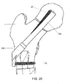
- a bone fixation system 100 which does not form part of the claimed invention, comprises a bone plate 102 sized and shaped for placement on a target portion of femoral shaft opposite the femoral head (i.e., over a location through which an axis of the femoral neck passes).
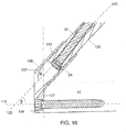
- the bone plate 102 comprises a first portion 104 shaped to engage an outer surface of the target portion of the femur along a first portion axis parallel to an axis of the shaft of the femur and a second portion 106 extending away from the first portion along a second portion axis 120 angled with respect to the first plane at an angle selected so that, when the first portion 104 is positioned over the target portion of the femur, the second portion axis 120 extends along the axis of the femoral neck.
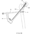
- the first and second portions 104, 106 are angled such that a bone contacting surface 107 of the first portion 104 encloses an angle ⁇ of approximately 130° relative to the second portion axis 120, as shown in Fig. 10 .
- the second portion axis 120 encloses an angle ⁇ of approximately 40° relative to a locking hole axis 110 of a locking hole 108 extending through the plate 102.
- the angle ⁇ may be 45°.
- the locking hole axis 110 in this example extends substantially perpendicular to the first portion axis.
- the orientation of the locking hole axis 110 may be varied as desired.
- the locking hole 108 includes a multi-faceted surface such as threading 112 to threadedly engage a corresponding threading on a shaft 12 of a bone fixation element 10 (e.g., a bone screw) inserted therethrough.
- the bone fixation element 10 may be a standard locking screw known in the art.
- a proximal portion of the locking hole 108 may include a non-threaded recess 114 to seat a head 14 of the bone fixation element 10 as would be understood by those skilled in the art.
- An outer surface of the first portion 104 may be substantially rounded such that the first portion 104 has a smooth outer profile preventing soft tissue irritation.
- the second portion 106 is substantially cylindrical and extends from the first portion 104 to a distal end 116 along a length selected so that, when the first portion 104 is positioned over the target portion of the femur, the second portion 106 extends through the femoral neck to a desired position within the femoral head.
- a central elongated channel 118 extends through the second portion along the second portion axis 120.
- An outer surface of the channel is substantially smooth with the exception of an abutment 122 adjacent the distal end 116.
- the abutment 122 extends proximally into the channel 118 a predetermined distance and includes a proximal seat 124 and an elongated face 126.
- the proximal seat 124 provides a stop for an implant shaft 130 while the face 126 prevents and/or minimizes a rotation of the shaft 130 relative to the bone plate 102.
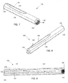
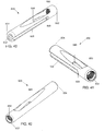
- the bone fixation system 100 further comprises an implant shaft 130 for insertion through the plate 102 along the axis of the femoral neck and the second portion axis 120 into the femoral head.
- the shaft 130 is formed as a an elongated substantially cylindrical member extending from a proximal end 132 to a distal end 134 along a central longitudinal axis 136.
- a diameter of the implant shaft in this example is approximately 10 mm. However, other dimensions may be used to accommodate difference in patient anatomy.
- the distal end 134 may be blunt to prevent the implant shaft 130 from cutting through the bone 1.
- An outer surface of the implant shaft 130 comprises an elongated cutout 138 extending from the proximal end 132 to the distal end 134 and forming a flat surface configured to engage the face 126 of the abutment 122 preventing rotation of the shaft 130 relative to the plate 102.
- a shape of the cutout 138 is selected so that, when implanted, forces tending to rotate the fractured femoral head relative to the femoral shaft are countered, resulting in the femoral head being kept in a desired stable alignment with the femoral shaft. That is, the cutout 138 eliminates the need for a friction fit between the implant shaft 130 and the second portion 106 to prevent a rotation of the implant shaft 130.
- the cutout 138 is a portion of an outer surface of the implant shaft 130 milled or otherwise formed to define a substantially planar face which engages the face 126 in an operative configuration, as will be described in greater detail later on.
- a proximal end of the cutout 138 comprises a tab 140 extending radially therefrom by a distance selected to permit the tab 140 to engage the seat 124 preventing the implant shaft 130 from being inserted distally past the seat 124 defining a maximum extent by which the shaft 130 may be inserted into the bone.
- the implant shaft 130 engages the bone plate 102 via a form fit.
- the form fit engagement permits lateral and medial telescoping migration of the implant shaft 130 relative to the bone plate 102 after implantation. This migration permits the implant shaft 130 to move laterally as the head of the bone moves to a corrected position during healing.
- the implant shaft 130 comprises a first channel 142 extending longitudinally therethrough from the proximal end 132 to the distal end 134 in alignment with the central longitudinal axis 136.
- the first channel 142 is dimensioned to receive a guide wire (e.g., a Kirschner wire) therethrough to guide insertion of the implant shaft 130 into the bone.
- the implant shaft 130 further comprises a substantially cylindrical second channel 144 extending therethrough along an axis 148 from the proximal end 132 to a distal opening 146 on a side wall of the implant shaft 130.
- the axis 148 in this example is angled at approximately 7.5° relative to the central longitudinal axis 136.
- the angle may be 5°, 6°, 8° or any other angle greater than 5°. In yet another example, the angle may range between 0° and 5°.
- the distal opening 146 of the second channel 144 is circumferentially separated from the cutout. Due to the angular orientation of the second channel 144 relative to the implant shaft 130, an opening of the second channel 144 at the distal opening 146 is substantially oval to permit a shaft 22 of an anti-rotation screw 20 inserted therethrough to exit therefrom. Specifically, the second channel 144 has a substantially circular cross-section. However, due to the second channel 144 exiting the implant shaft 130 at an oblique angle, as shown in Figs.
- the distal opening 146 has an oval shape.
- the proximal end of the second channel 144 is formed with a threaded portion 150 to threadedly engage threading formed on the shaft 22 of the anti-rotation screw 20.
- the threaded portion 150 may have a tapered diameter to engage a tapered diameter of a head 24 of the anti-rotation screw 20 the diameter of the threaded portion 150 being selected to prevent the head 24 from being inserted therepast.
- Figs. 11 - 20 depict an exemplary method of use of the bone fixation system 100.
- a patient is placed in a supine position on an operating table and the fractured bone 30 is provisionally brought into a corrected alignment via one or more of traction, abduction and internal rotation as would be understood by those skilled in the art.
- a straight lateral incision approximately 3-4 cm in length is made proximal to a tip of a greater trochanter.
- the iliotibial tract is then split lengthwise and the vastus lateralis muscle is detached dorsally from the intramuscular membrane.
- the proximal femoral shaft of a bone 1 is then exposed without retracting the periosteum.
- a guide wire is inserted through a center of the femoral head at a desired angle until a distal end of the guide wire extends into the subchondral bone, as those skilled in the art will understand. If desired one or more additional guide wires may be inserted into the femoral head as would be understood by those skilled in the art.
- a known reaming device (not shown) is then guided over the guide wire to ream a bore hole for the insertion of an implant. The reamer is then removed from the bone 30 and the physician measures the appropriate implant length and selects an appropriately sized implant shaft 130.
- the implant shaft 130 is then inserted through the channel 118 of the second portion 106 of the bone plate 102 until engagement of the tab 140 with the seat 126 prevents further distal movement of the implant shaft 130.
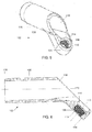
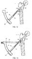
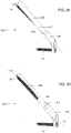
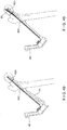
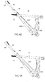
- the assembled bone plate 102 and implant shaft 130 are then attached to an insertion instrument 40 including an arm portion 42 and an elongated shaft portion 44, a distal end 46 of which removably grasps the bone plate 102, as shown in Figs. 11 - 13 .
- the arm portion 42 is depicted with a curvature, any other shape may be used.
- the arm portion 42 includes a first opening 48 extending through a first portion at a first end thereof and a second opening 50 extending through a second portion at a second end thereof.
- the first opening 48 has a substantially circular cross-section to permit insertion of a substantially cylindrical first protection sleeve 60 therethrough.
- the second opening 50 has a substantially oblong (e.g., oval, rectangular, etc.) cross-sectional shape to permit insertion of a second protection sleeve 70 therethrough, as will also be described in greater detail below.
- the bone plate 102 is slidably inserted into engagement with the distal end 46, although other attachment mechanisms may be employed.
- the exemplary system 100 eliminates the need for an impactor to drive the bone plate 102 and implant shaft 130 into the bone.
- an impactor (not shown) may be used to first impact the implant shaft 130 into the femoral neck of a bone 1 and into the femoral head and subsequently impact the bone plate 102 into a lateral portion of the bone 1 until the plate 102 seats flush against the bone.
- an impactor may be inserted through the bone plate 102 against the implant shaft 130 to impact the system 100 into the bone.
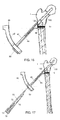
- the impactor (not shown) and the guide wire (not shown) may then be removed from the bone, leaving the insertion instrument 40 and system 100 positioned in the bone, as shown in Figure 14 .
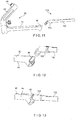
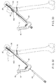
- a first protection sleeve 60 is then inserted through the first opening 48 in the insertion instrument 40.
- the first protection sleeve 60 may extend through the first opening 48 and into the distal end 46 of the insertion instrument 40 at a predetermined angle relative to the angle of the elongated shaft portion 44.
- the first protection sleeve 60 and elongated shaft 44 enclose an angle of approximately 40°, although other angles may be used.
- the first protection sleeve 60 guides the drilling of a hole into the bone 1 to permit insertion of the bone fixation element 10 (i.e., a bicortical shaft screw) therein.
- a drilling mechanism known in the art may be inserted through the first protection sleeve 60 to drill an opening through the locking hole 108 of the bone plate 102 and into the bone 1.
- the drilling mechanism may then be removed and the bone fixation element 10 may be inserted through the first protection sleeve 60 and bone plate 102 and into the bone 1.
- Dimensions of the bone fixation element 10 are selected to permit bicortical insertion thereof through the bone 1, as those skilled in the art will understand.
- the first protection sleeve 60 may then be removed from the insertion instrument, leaving the bone fixation element 10 in place within the bone 1.
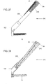
- the second protection sleeve 70 may comprise a first elongated shaft portion 72 having a first channel 74 extending therethrough, the first elongated shaft portion 72 being insertable through the insertion instrument. In an operative configuration, a longitudinal axis 75 of the first channel 74 is substantially aligned with the longitudinal axis 136 of the implant shaft 130.
- the second protection sleeve 70 further comprises a second elongated shaft portion 76 having a second channel 78 extending therethrough, a longitudinal axis 77 of the second elongated shaft portion 76 being offset from the longitudinal axis 75 by approximately 5E to align with the axis 148 of the implant shaft 130, as described in greater detail earlier and depicted in Fig. 9 .
- the elongated shaft 44 may comprise an elongated slot (not shown) on a side wall thereof to permit insertion of second protection sleeve 70 to the position depicted in Fig. 18 .
- a drilling mechanism (not shown) may be inserted through the second channels 78 and 144 to prepare the bone 1 for the anti-rotation bone screw 20.
- a driving mechanism (not shown) may then be used to insert the anti-rotation screw 20 through the second protection sleeve 70 and implant shaft 130 and into the bone 1.
- the second protection sleeve 70 and insertion instrument 40 may then be removed from the body, leaving the system 100 implanted in the bone 1.
- the head of the femur is prevented from rotation relative to the bone 1 via the anti-rotation screw 20 and bone plate 102.
- the shaft 130 is permitted to migrate within a desired range relative to the bone plate 102.
- the combined implant shaft 130 and bone fixation element anti-rotation screw 20 inserted therethrough are capable of migrating a distance x from the configuration of Figs. 21 - 22 to the configuration of Figs. 23 - 24 .
- this migration of the implant shaft 130 relative to the bone plate 102 minimizes the risk of medial perforation of the implant shaft 130 through the femoral head after implantation and as the bone heals.
- the exemplary method depicts the insertion of the bicortical screw 10 first, followed by the insertion of the anti-rotation screw 20, the order of insertion may be changed to suit, for example, a surgeon's preference.
- the method of insertion for the system 800 as described below is directed to the insertion of an anti-rotation screw first, followed by a bi-cortical screw.
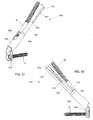
- Figs. 25 - 26 depict a system 200 according to a first alternate example.
- the system 200 is formed substantially similarly to the system 100, wherein like elements have been referenced with like reference numerals.
- the system 200 comprises a bone plate 102 and an implant shaft 230.
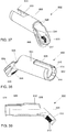
- the implant shaft 230 is formed substantially similarly to the implant shaft 130 with the exception of a reduced diameter distal portion 240.
- the implant shaft 230 extends from the proximal end 132 to the distal end 234.
- the reduced diameter distal portion 240 extends proximally from the distal end 134 a predetermined distance.
- the reduced diameter portion 240 reduces the amount of bone removal needed for insertion of the implant shaft 230 into the bone and has a wider spread between the distal end 234 of the implant shaft 230 and distal end of the anti-rotation screw 20.
- Figs. 27 - 28 depict a system 300 according to a second alternate example.
- the system 300 is formed substantially similarly to the system 100, wherein like elements have been referenced with like reference numerals.
- the system 300 comprises a bone plate 102 and an implant shaft 330 formed substantially similarly to the implant shaft 130 with the exception of a threaded distal portion 340.
- the implant shaft 330 extends from a proximal end 132 to a distal end 234 with the threaded distal portion 340 extending proximally from the distal end 134 a predetermined distance.
- the threaded distal portion 340 aids in retention of the implant shaft 330 within the bone 1.
- Fig. 29 depicts a system 400 according to a third alternate example.
- the system 400 is formed substantially similarly to the system 100, wherein like elements have been referenced with like reference numerals.
- the system 400 comprises a bone plate 102 and an implant shaft 430.
- the implant shaft 430 is formed substantially similarly to the implant shaft 130 with the exception of a position and angle of a channel 444 extending therethrough.
- the channel 144 of the system 100 extends from the proximal end 132 to a distal opening 146 positioned on a cranial surface of the implant shaft in an operative configuration.
- the channel 444 extends from the proximal end 132 to a distal end 446 positioned on a caudal surface of the implant shaft 430 in an operative configuration.
- a channel axis 448 of the channel 444 is angled at approximately -5° relative to the central longitudinal axis 136. However, those skilled in the art will understand that this angle may vary as desired.
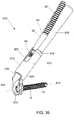
- Fig. 30 depicts a system 500 according to a fourth alternate example.
- the system 500 is formed substantially similarly to the system 100, wherein like elements have been referenced with like reference numerals.
- the system 500 comprises a bone plate 102 and an implant shaft 530 formed substantially similarly to the implant shaft 130 with the exception of a position and angle of a channel 544 extending therethrough.
- the channel 544 extends from the proximal end 132 to a distal end 546 positioned on a surface of the implant shaft 530 which, in an operative configuration, faces one of an anterior and a posterior direction.
- a physician may determine which of the systems 100, 400 and 500 to use in accordance with, for example, a size and location of a fracture in the bone, as those skilled in the art will understand.
- Figs. 31 - 33 depict a system 600 according to a fifth alternate example.
- the system 600 is formed substantially similarly to the system 100, wherein like elements have been referenced with like reference numerals.
- the system 600 comprises a bone plate 602 and the implant shaft 130, bone plate 602 being formed substantially similarly to the implant shaft 130 with the exception of an additional locking hole extending therethrough.
- the bone plate 602 comprises a central longitudinal channel 118.
- a first locking hole 608 is positioned caudally of the central longitudinal channel 118 and is substantially similar to the locking hole 108.
- a second locking hole 609 extends through the bone plate 602 cranially of the central longitudinal channel 118.
- a hole axis 610 of the second locking hole is substantially parallel to the channel axis 120 of the central longitudinal channel 118 such that a bone fixation element 10' inserted therethrough does not intersect any other portion of the system 600.
- An exemplary insertion method for the system 600 is substantially similar to the method disclosed earlier with respect to system 100. However, once the first and second bone fixation elements 10, 20 have been inserted, a third drill sleeve 80 is inserted through the insertion instrument 40 to align with the second locking hole. A drilling mechanism (not shown) is inserted through the drill sleeve 80 and into the bone to define the trajectory of the bone fixation element 10'. A driving mechanism (not shown) is then inserted through the drill sleeve 80 to screw the bone fixation element 10' into the bone 1.
- the exemplary system 600 provides added structural support to the bone 1 and may be particularly advantageous in bones with multiple fractures or otherwise weaker bones.
- the systems 100, 200, 300, 400, 500 and 600 may be manufactured and packaged as a kit 700 including the bone plate 102, 602, implant shaft 130, 230, 330, 430, 530, and anti-rotation screw 20 along with instructions for implantation as described above.
- the implant shaft 130, 230, 330, 430, 530 and anti-rotation screw 20 may be provided in corresponding dimensions to one another.
- the kit may be sold in various implant shaft lengths to suit the requirements of a particular procedure.
- the bone fixation element 10 may be offered separately.
- the kit 700 may include a molded packaging 702 formed of plastic or another suitable material having a removable seal 704 provided thereover, the seal 704 maintaining the sterility of the system.
- Figure 35 depicts a single-use kit for the instruments required for the completion of a bone fixation procedure, as described above with respect to the exemplary method of use for the system 100.
- a kit 750 may include the insertion instrument 40, the corresponding removable shaft portion 44 and the first and second protection sleeves 60, 70.
- the removable shaft portion 44 is attached to an elongated shaft 46, which is further attached to the second protection sleeve 70 via a Y-connector.
- a side wall of the insertion instrument 40 includes a slot (not shown) permitting insertion of the Y-connector therepast.
- the removable shaft portion 44 further comprises a tab 48 including a protruding distal end 49 extending radially away therefrom.
- the tab 48 is received through the second opening 50 with a snap-fit engagement. Specifically, the tab 48 is deformed radially inward when being inserted through the second opening 50. Once moved thereinto, the tab 48 moves radially outward to assume its initial configuration so that the protruding distal end 49 is received within a corresponding portion of the second opening 50, thus locking the shaft portion 44 to the instrument 40.
- the insertion instrument 40 may be made of a low-cost plastic injection molding while the protection sleeves 60, 70 and shaft portion 44 may be formed of a low-cost metal injection molding. In another example, the insertion instrument 40 may be made of standard parts (e.g., standard tubing, etc.) connected to form the depicted structure.
- the kit 750 may be sold as a single unit for use with any of the exemplary systems 100, 200, 300, 400, 500, 600, 800 disclosed herein.
- Figs. 36 - 50 depict a system 800 according to an embodiment according to the invention.
- the system 800 is formed substantially similarly to the system 100, wherein like elements have been referenced with like reference numerals.
- the system 800 comprises a bone plate 802 and an implant shaft 830.
- the implant shaft 830 is formed substantially similarly to the implant shaft 130 with the exception of the structural differences noted below.
- the bone plate 802 comprises a first portion 804 shaped to engage an outer surface of the target portion of the femur along a first portion axis parallel to an axis of the shaft of the femur and a second portion 806 extending away from the first portion along a second portion axis angled with respect to the first plane at an angle selected so that, when the first portion is positioned over the target portion of the femur, an axis of the second portion extends along the axis of the femoral neck.
- the first portion 804 comprises a locking hole 808 extending through the plate 802 along a locking hole axis 810 which extends substantially perpendicular to a first portion axis.
- the locking hole 808 is formed substantially similar to the locking hole 108 of the system 100 and may include a multi-faceted surface such as threading 812 to threadedly engage a corresponding threading on the shaft 12 of the bone fixation element 10 (e.g., a bone screw) inserted therethrough.
- An outer surface of the first portion 804 is substantially rounded such that the first portion 804 has a smooth outer profile substantially matching that of the target portion of the femur.
- the outer surface of the first portion 804 further comprises one or more recesses 805 configured and dimensioned to permit grasping of the bone plate 802 by the insertion instrument 40, as will be described in greater detail with respect to the exemplary method below.
- the recess 805 may extend substantially parallel to an axis of the first portion 804.
- first and second recesses 805 may be provided on opposing walls of the first portion 804 to permit grasping of the bone plate 802. Dimensions of each of the recesses may be selected to conform to the dimensions of a gripping portion of the implant holder
- the second portion 806 is substantially cylindrical and extends from the first portion 804 to a distal end 816.
- a central elongated channel 818 extends through the second portion along a second portion axis 820.
- An outer surface of the channel 818 is substantially smooth with the exception of an abutment 822 adjacent the distal end 816.
- the abutment 822 extends radially into the channel 818 a predetermined distance and is bordered on both sides by grooves 824.
- a cutout 826 extends proximally from the distal end 816 of the second portion.
- the cutout 826 is substantially rectangular with rounded corners and is open to the distal end 816.
- the cutout 826 is positioned so that, in an operative configuration, the cutout faces a cranial direction. Dimensions of the cutout 826 may be selected to permit the anti-rotation screw 80 to extend therefrom, as shown in Figs. 35 and 45 - 46 . That is, the cutout 826 prevents the need for advancement of the implant shaft 830 out of the bone plate 102 beyond a threshold distance. Rather, in smaller bones, the implant shaft 830 may extend out of the bone plate 802 by only a minimal required distance, with a distal end 846 of the second channel 844 be housed within the second portion 806. In an operative configuration, the anti-rotation screw 80 may be inserted through the implant shaft 830 to extend out of the cutout 826.
- the cutout 826 may be formed with any length to permit use of the system 800 in bones having varying dimensions. Furthermore, for use in longer bones, the cutout 826 may optionally be omitted. Furthermore, the cutout 826 allows telescoping of the implant shaft 830 relative to the bone plate 802.
- the second portion 806 further comprises first and second recesses 828 provided on opposing walls adjacent a proximal end of the channel 818.
- the first and second recesses are configured and dimensioned to permit insertion of a corresponding portion of a locking core therethrough to guide insertion of the bone plate 802 over the bone, as will be described in greater detail below.
- the implant shaft 830 is formed as a an elongated substantially cylindrical member extending from a proximal end 832 to a substantially blunt distal end 834 along a central longitudinal axis 836.
- An outer surface of the implant shaft 830 comprises an elongated cutout 838 extending from a proximal end 839 to the distal end 834, the cutout 838 have a shape corresponding to the shape of the abutment 822 and grooves 824 to permit engagement therewith. As described in greater detail with respect to the system 100, this engagement prevents rotation of the shaft 830 relative to the plate 802.
- engagement of the abutment 822 with the proximal end 839 of the cutout 838 prevents the shaft 130 from extending distally out of the plate 802, defining a maximum extent by which the shaft 830 may be inserted into the bone. Furthermore, due to the hemispherical shape of the cutout 838, a rotational force applied to the implant shaft 830 after implantation is converted to a substantially perpendicular moment arm, preventing wedging of the implant shaft 830 against walls of the second portion 806. The prevention of the wedging of the implant shaft 830 also prevents high-friction forces that may influence the ability of the implant shaft 830 to telescope relative to the plate 802.
- the implant shaft 830 comprises a first channel 842 extending longitudinally therethrough from the proximal end 832 to the distal end 834 in alignment with a central longitudinal axis 836.
- the first channel 842 is dimensioned to receive a guide wire (e.g., a Kirschner wire) therethrough to guide insertion of the implant shaft 830 into the bone.
- the implant shaft 830 further comprises a second channel 844 extending therethrough along an axis 848 from the proximal end 132 to a distal opening 846 on a side wall of the implant shaft 830, the distal opening 846 being circumferentially separated from the cutout 838.
- the distal opening 846 is substantially oval to permit a shaft 82 of an anti-rotation screw 80 inserted therethrough to exit therefrom. Similar to the distal opening 146, the distal opening 846 is oval due to an oblique position of the substantially circular second channel 844 relative to the implant shaft 830.
- the proximal end of the second channel 844 includes threading 850 to threadedly engage threading formed on the shaft 82 of the anti-rotation screw 80, as will be described in greater detail below. Whereas the threading 150 of the implant shaft 130 is substantially tapered, the threading 850 is substantially cylindrical.
- the anti-rotation screw 80 extends from a head 84 at a proximal end and along the shaft 82 to a distal end 86.
- the shaft 82 includes a first portion 88 having a first outer diameter selected to permit engagement with the threading 850 of the implant shaft 830.
- the first portion 88 includes a first threaded region 89 including a double-lead thread to aid in engagement thereof with the threading 850.
- the first portion 88 also includes a non-threaded tapered region 90 shaped to allow telescoping of the anti-rotation screw 80 when inserted into a target orientation in the bone.
- the first portion 88 preferably has a substantially tapered shape corresponding to a tapered shape of the second channel 844.
- a second non-threaded portion 92 extends distally from the first portion 88.
- a diameter of the second portion 92 is greater than a diameter of the tapered region 90, forming a telescoping stop 94 at a junction thereof.
- the second portion 92 extends out of the implant shaft 830 and into the bone.
- a third threaded portion 96 extends distally from the second non-threaded portion 94 and includes single lead spongiosa threading configured to engage bone in an operative configuration, as will be described in greater detail with respect to the exemplary method below.
- the double-lead thread of the first threaded region 89 matches a pitch of the single-lead thread of the third portion 96.
- a higher pitch of the thread in the third threaded portion 96 can be used to facilitate compression of the femoral head onto the shaft 82.
- An exemplary method of use of the bone fixation system 800 is substantially similar to the method of use of the system 100 described in detail earlier with respect to Figures 11 - 20 .
- one or more guide wire are inserted into a center of the femoral head at a desired angle until a distal end of the guide wire extends into the subchondral bone, as those skilled in the art will understand.
- a known reaming device (not shown) is then guided over the guide wire to ream a bore hole for the insertion of an implant according to the invention.
- the implant shaft 830 is then inserted through the channel 818 of the second portion 806 of the bone plate 802 until engagement of the abutment 822 with the proximal end 839 of the cutout 838 prevents further distal movement of the implant shaft 830.
- the assembled bone plate 802 and implant shaft 830 are then attached to the insertion instrument 40 including an arm portion 42 and an elongated shaft portion 44, a distal end 46 of which removably grasps the recesses 805 of the bone plate 802.
- an impactor may be inserted through the bone plate 802 and implant shaft 830 to impact the system 800 into the bone.
- the impactor (not shown) and the guide wire (not shown) may then be removed from the bone, leaving the insertion instrument 40 and system 800 positioned in the bone.
- the second protection sleeve 70 is then inserted through the second opening 50 and through the elongated shaft 44 until a distal end thereof is seated against the implant shaft 830.
- a drilling mechanism (not shown) may be inserted through the second channels 78 and 844 to prepare the bone 1 for the anti-rotation bone screw 80.
- a driving mechanism (not shown) may then be used to insert the anti-rotation screw 80 through the second protection sleeve 70 and implant shaft 830 and into the bone 1.
- the second protection sleeve 70 and insertion instrument 40 may then be removed from the body, leaving the system 800 implanted in the bone 1. Once implanted, the head of the femur is prevented from rotation relative to the bone 1 via the anti-rotation screw 80 and bone plate 802.
- the first protection sleeve 60 is then inserted through the first opening 48 in the insertion instrument 40 to guide the drilling of a hole into the bone 1 to permit insertion of the bone fixation element 10 (i.e., a bicortical shaft screw) therein.
- a drilling mechanism known in the art may be inserted through the first protection sleeve 60 to drill an opening through the locking hole 808 of the bone plate 802 and into the bone 1.
- the drilling mechanism may then be removed and the bone fixation element 10 may be inserted through the first protection sleeve 60 and bone plate 802 and into the bone 1.
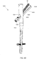
- Figs. 51 - 52 depict a system 900 according to yet another embodiment of the invention.
- the system 900 is formed substantially similarly to the system 800 and includes a bone plate 902 having first and second portions 904, 906 and an implant shaft 930 with one or more elastic deflecting structures at a distal end thereof.
- the implant shaft 930 includes an elongated channel 942 extending therethrough from a proximal end (not shown) to a distal end 934.
- a second channel 944 extends therethrough at an angle relative to a central longitudinal axis thereof to house the anti-rotation screw 80, as described in greater detail with respect to earlier embodiments.
- the implant shaft 930 further comprises a plurality of elongated slots 950 extending proximally from the distal end 934 and terminating at a substantially circular cutout at proximal ends 952.
- the implant shaft 930 may include two slots 950 provided on opposing walls of the implant shaft 930 to define two compliant arms 954. It is noted however, that any number of slots 950 may be provided without deviating from the scope of the invention.
- the compliant arms 954 increase an overall elasticity of the implant shaft 930 by distributing a peak load applied to the distal end 934, permitting the shaft 930 to deform instead of fracturing when subjected to excessive loads. By allowing for deformation of the implant shaft 930, the compliant arms 954 prevent inadvertent penetration of the implant shaft 930 through the bone, as those skilled in the art will understand.
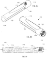
- Fig. 53 depicts a system 1000.
- the system 1000 depicts an implant shaft 1030 formed substantially similar to the implant shafts 130, 830 described above. However, instead of being inserted through a bone plate, the implant shaft 1030 is insertable through an intramedullary nail 1002.
- the intramedullary nail 1002 includes a transverse opening 1004 extending therethrough, the transverse opening 1004 having a shape formed by first and second overlapping circular channels 1006, 1008.
- the first circular channel 1006 is configured to permit insertion of the implant shaft 1030 therethrough and extends through the intramedullary nail 1002 at a first angle.
- the second circular channel 1008 is open to the first circular channel and extends through the intramedullary nail 1002 at a second angle different than the first angle.
- an angle of the second circular channel 1008 substantially matches an angle of the second channel 144 relative to the first channel 142 of the implant shaft 1030.
- the anti-rotation screw 80 inserted through the second channel 144 is guided through the second channel 1008 and out of an opposing wall of the intramedullary nail 1002.
- An outer wall of the implant shaft 1030 may include a cutout 1038 configured to engage a respectively shaped abutment (not shown) provided in the first channel 1006. Engagement of the abutment (not shown) with the cutout 1038 prevents rotation of the implant shaft 1030 relative to the transverse opening 1004. Furthermore, engagement of the abutment (not shown) with a proximal end 1039 of the cutout 1038 limits a depth of insertion of the implant shaft 1030 into the bone.
- Figs. 54 - 56 depict an implant shaft 1130.
- the implant shaft 1130 is formed substantially similarly to the implant shafts 130, 830 except as noted hereinafter.
- the implant shaft 1130 may be used with any of the bone plates 102, 602, 802, 902 and intramedullary nails 1002 disclosed above.
- the implant shaft 1130 is formed as an elongated substantially cylindrical member extending from a proximal end 1132 to a substantially blunt distal end 1134 along a central longitudinal axis 1136.
- An outer surface of the implant shaft 1130 comprises an elongated cutout 1138 extending from a proximal end 1139 to the distal end 1134, the cutout 1138 being formed substantially similar to the cutout 838.
- the implant shaft 1130 does not comprise a central longitudinal channel extending therethrough. Rather, the implant shaft 1130 comprises only a channel 1144 extending therethrough along an axis 1148 from the proximal end 1132 to a distal opening 1146 on a side wall of the implant shaft 1130 to receive, for example, an anti-rotation screw (not shown) therethrough. Accordingly, unlike earlier examples, which may optionally be guided over a pre-positioned guide wire into the bone, the exemplary implant shaft 1130 may be inserted into the bone after removal of the guide wire therefrom. That is, the implant shaft 1130 may be guided into the bone via a hole pre-drilled therein.
- any of the implant shafts and bone plates disclosed herein may optionally be coated with Diamond-Like Carbon (DLC) to prevent osseointegration thereof, as those skilled in the art will understand and/or to reduce friction and therefore improve telescoping between the bone plate and the implant shaft.
- DLC Diamond-Like Carbon
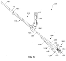
- Figs. 57 - 62 depict a kit 1200 as required for the completion of a bone fixation procedure.
- the kit 1200 is formed substantially similarly to the kit 750 described earlier, with like elements being referenced with like reference numerals. However, whereas the kit 750 is configured for single-use, the kit 1200 may be used any number of times to perform multiple procedure. It is noted that the kit 1200 may also be configured for single-use. Furthermore, whereas the removable shaft portion 44 of the kit 750 engages the instrument 40 with a click/snap-fit engagement, a removable shaft portion 1250 of the kit 1200 engages an instrument 1240 with a threaded engagement, as will be described in greater detail hereinafter.
- the kit 1200 may also employ the snap-fit engagement of kit 750.
- the kit 1200 includes an insertion instrument 1240 extending from a proximal end 1242 including a curved arm 1244 to a distal end 1246.
- a first opening 1247 extends through the arm 1244 to guide the first protection sleeve 60 therethrough, as will be described in greater detail with respect to the exemplary method below.
- a second opening 1248 extends into the proximal end 1242 permitting insertion of the removable shaft portion 1250 thereinto.
- the instrument 1240 also comprises an elongated slot 1249 on a side wall thereof to accommodate the width of the shaft portion 1250 when inserted therein.
- the removable shaft portion 1250 includes a first elongated shaft portion 1252 extending from a first proximal end 1254 to a distal end 1256 and including a first channel 1258 extending therethrough. In an operative configuration, a longitudinal axis 1260 of the first channel 1258 is substantially aligned with the longitudinal axis 136 of the implant shaft 130.
- the removable shaft portion 1250 further comprises a second elongated shaft portion 1262 formed substantially similarly to the second protection sleeve 70 and extending from a second proximal end 1264 to the distal end 1256.
- a second channel 1268 extends through the second shaft portion 1262 along a longitudinal axis 1270 offset from the longitudinal axis 1260 by approximately 7.5° to align with the axis 148 of the implant shaft 130, as described in greater detail with respect to earlier examples.
- the first and second elongated shaft portions 1252, 1262 extend to a common distal end 1256 via a connecting element 1280.
- the connecting element 1280 according to this example comprises an elongated slot 1282 extending through a side wall thereof to permit insertion of the anti-rotation screw 20 therethrough and through the implant 130 to extend into the bone, as will be described in greater detail with respect to the exemplary method below.
- the first elongated shaft portion 1252 includes a locking element 1284 at the first proximal end 1254.
- the locking element 1284 includes a threaded portion 1286 and a screw 1288 which may be rotated (e.g., manually by a user) to screw the threaded portion 1286 into a corresponding threaded region (not shown) provided within the opening 1248 of the instrument 1240.
- rotation of the screw 1288 rotates the entire first elongated shaft portion 1252 relative to the connecting element 1280.
- the first elongated shaft portion 1252 is removably attached to the connecting element 1280.
- first elongated shaft portion 1252 is permanently attached to the connecting element 1280 and axially movable relative thereto within a predetermined range of motion corresponding to an axial length of the threaded portion 1286 to permit screwing and unscrewing thereof into the instrument 1240, as those skilled in the art will understand.
- the second elongated shaft portion 1262 may also be either permanently or removably attached to the connecting element 1280 as those skilled in the art will understand.
- a patient is placed in a supine position on an operating table and a fractured femur is provisionally brought into a corrected alignment via one or more of traction, abduction and internal rotation as would be understood by those skilled in the art.
- An incision is formed in the skin and the bone is reamed to create a bore hole for the insertion of an implant according to the invention.
- the assembled bone plate 102 and implant shaft 130 are then attached to the insertion instrument 1240 via a sliding engagement between the distal end 1246 and a proximal end of the bone plate 102, as described in greater detail in earlier examples.
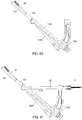
- the removable shaft portion 1250 is then inserted into the opening 1248 such that the distal end 1256 extends adjacent to the distal end 1246 of the instrument 1240, as shown in Fig. 58 .
- the screw 1288 is then rotated to threadedly drive the first elongated shaft portion 1252 into the instrument 1240 and into threaded engagement with a threaded portion (not shown) of the opening 1248.
- the locking element 1284 is configured so that, when the screw 1288 comes into contact with an outer surface of the instrument 1240, the first elongated shaft portion 1252 is locked against rotation or axial movement relative to the instrument 1240.
- a drilling mechanism (not shown) may be inserted through the channel 1270 to prepare the bone for the anti-rotation bone screw 20.
- a driving mechanism (not shown) may then be used to insert the anti-rotation screw 20 through the second elongated shaft portion 1262 and implant shaft 130 and into the bone, as shown in Figs. 59 and 60 .
- a distal end of the anti-rotation screw 20 is separated from a distal end of the implant shaft 130 by approximately 5 mm. As shown in Figs.
- the first protection sleeve 60 is then inserted through the first opening 1247 in the insertion instrument 1240.
- the first protection sleeve 60 extends through the first opening 1247 and into the distal end 46 of the insertion instrument 40 at a predetermined angle relative to the angle of the first elongated shaft portion 1252 (e.g., 45°, etc.) until a distal end thereof is in contact with the locking hole 108, as shown in the partial cutaway view of Fig. 62 .
- An optional drilling mechanism known in the art may be inserted through the first protection sleeve 60 to drill an opening through the locking hole 108 of the bone plate 102 and into the bone.
- the drilling mechanism may then be removed and the bone fixation element 10 may be inserted through the first protection sleeve 60 and bone plate 102 and into the bone 1.
- the first protection sleeve 60 and instrument 1240 may then be removed, leaving the system 100 implanted in the bone.
- the exemplary method depicts the insertion of the anti-rotation screw 20 followed by the bicortical screw 10 first, the order of insertion may be changed to suit, for example, a surgeon's preference.
- the kit 1200 is described with respect to the system 100, the kit 1200 may be employed with any of the systems 200, 300, 400, 500, 600, 800 disclosed herein.
- the present invention may be used in a method of implanting a bone fixation assembly into a bone, comprising: inserting an implant shaft through a second opening extending through a bone plate, the bone plate having a first plate portion and a second plate portion, the first plate portion having a first opening extending therethrough along a first opening axis and the second plate portion having the second opening extending therethrough along a second opening axis, the implant shaft extending from a proximal end to a distal end along a central longitudinal axis and including a first channel extending from the proximal end to a side opening formed in a side wall thereof along a first channel axis; inserting the implant shaft into a shaft of the bone until the first portion of the bone plate is positioned over an outer surface of the bone and a portion of the second portion is received within the bone; and inserting an anti-rotation screw through the first channel until a head of the screw locking engages the proximal end of the first channel and a distal end of a shaft
- the aforementioned method may be performed such that the implanted anti-rotation screw is offset from the central longitudinal axis by approximately 5°.
- the method may further comprise the step of aligning a first surface provided on the outer wall of the implant shaft with a corresponding second surface on an outer wall of the second opening to prevent rotation of the implant shaft relative to the bone plate.
- the first surface may be one of flat and hemispherical.
- the method may further comprise the step of inserting a first locking screw through the first opening and into the bone.
- the method may further comprise the step of inserting a second locking screw through a third opening extending through a third portion of the bone plate and into the bone.
- the method may further comprise the step of inserting a guide wire into the bone at a desired angle to guide the insertion of the implant shaft into the bone.
- the implant shaft may include a second channel extending from the proximal end to the distal end along a second channel axis, the second channel receiving the guide wire therethrough to aid in insertion.
- the present invention may further be used in a method of assembling a bone fixation assembly, comprising: inserting an implant shaft through a second opening extending through a bone plate, the implant shaft engaging the second opening with a form fit, the bone plate having a first plate portion and a second plate portion, the first plate portion having a first opening extending therethrough along a first opening axis and the second plate portion having the second opening extending therethrough along a second opening axis, the implant shaft extending from a proximal end to a distal end along a central longitudinal axis and including a first channel extending from the proximal end to a side opening formed in a side wall thereof along a first channel axis.
Claims (15)
- Knochenbefestigungssystem (800), umfassend:einen länglichen Implantatschaft (830), der sich von einem proximalen Ende (832) zu einem distalen Ende (834) entlang einer Mittellängsachse (836) erstreckt und einen zweiten Kanal (844), der sich vom proximalen Ende (832) zu einer Seitenöffnung (846) erstreckt, die in einer Seitenwand des Implantatschafts (830) entlang einer zweiten Kanalachse (848) ausgebildet ist, und einen ersten Kanal (842) umfasst, der sich vom proximalen Ende (832) zum distalen Ende (834) entlang einer ersten Kanalachse erstreckt; undeine Knochenplatte (802) mit einem ersten Plattenabschnitt (804) und einem zweiten Plattenabschnitt (806), wobei der erste Plattenabschnitt (804) eine erste Öffnung (808) aufweist, die sich entlang einer ersten Öffnungsachse (810) durch diese erstreckt, und der zweite Plattenabschnitt (806) eine zweite Öffnung (818) aufweist, die sich entlang einer zweiten Öffnungsachse (820) durch diese erstreckt, wobei die zweite Öffnung (818) zum Aufnehmen des Implantatschafts (830) durch diese konfiguriert ist, um dessen Einführen in einen Femurkopf zu ermöglichen, dadurch gekennzeichnet, dassder zweite Plattenabschnitt (806) ferner einen ersten Ausschnitt (826) umfasst, der sich durch eine Seitenwand davon erstreckt und zu einem distalen Ende des zweiten Abschnitts (806) offen ist, wobei der Ausschnitt (826) zum Aufnehmen eines Abschnitts einer Verdrehsicherungsschraube (80) bemessen und dimensioniert ist, die durch die zweite Öffnung (818) und den Implantatschaft (830) einführbar ist.
- Knochenbefestigungssystem nach Anspruch 1, wobei die ersten und zweiten Kanalachsen (836, 848) einen Winkel von 5°, 6°, 7,5° oder 8°, oder größer als 5° einschließen.
- Knochenbefestigungssystem nach Anspruch 1 oder 2, wobei die erste Öffnungsachse (810) und die zweite Öffnungsachse (820) einen Winkel von 50° einschließen.
- Knochenbefestigungssystem nach einem der Ansprüche 1 bis 3, wobei der erste Plattenabschnitt (804) zum Positionieren über einer Außenfläche des Knochens konfiguriert ist und der zweite Plattenabschnitt (806) zum teilweisen Einführen in den Knochen konfiguriert ist, wobei der zweite Plattenabschnitt (806) einen im Wesentlichen kreisförmigen Querschnitt aufweist.
- Knochenbefestigungssystem nach einem der Ansprüche 1 bis 4, wobei eine Seitenwand des Implantatschafts (830) eine erste flache Oberfläche (838) umfasst, die zum Eingriff in eine jeweilige zweite ebene Oberfläche (826) an einer Außenwand der zweiten Öffnung (818) konfiguriert ist, wobei der Eingriff der ersten und zweiten ebenen Oberflächen (838, 826) eine Drehung des Implantatschafts (830) relativ zur Knochenplatte (802) unterbindet, wobei vorzugsweise ein proximales Ende der ersten ebenen Oberfläche (826) einen ersten Vorsprung (824) umfasst, der zum Eingriff in ein proximales Ende der zweiten flachen Oberfläche (838) konfiguriert ist, um zu verhindern, dass sich der Implantatschaft (830) distal dorthin bewegt.
- Knochenbefestigungssystem nach einem der Ansprüche 1 bis 5, wobei der Implantatschaft (830) im Innern der zweiten Öffnung (818) formschlüssig gehalten wird.
- Knochenbefestigungssystem nach einem der Ansprüche 1 bis 6, wobei die erste Öffnung (808) zum Aufnehmen eines ersten Knochenbefestigungselements (10), das vorzugsweise eine bikortikale Feststellschraube ist, durch diese konfiguriert ist, wobei die erste Öffnung (808) vorzugsweise mit einem Gewinde zum Gewindeeingriff mit einem Gewinde einer durchgesteckten Feststellschraube versehen ist.
- Knochenbefestigungssystem nach Anspruch 7, wobei ein proximaler Abschnitt des zweiten Kanals eine mehrfach-facettierte Oberfläche (850) umfasst, die zum Eingriff mit einer entsprechenden Oberfläche (89) eines zweiten Knochenbefestigungselements (80) konfiguriert ist, das durch diese und aus der Seitenöffnung (846) in den Knochen eingeführt wird, wobei das zweite Knochenbefestigungselement (80) verhindert, dass sich der Femurkopf relativ zum Implantatschaft (830) dreht, wobei die mehrfach-facettierte Oberfläche vorzugsweise ein Gewinde umfasst.
- Knochenbefestigungssystem nach einem der Ansprüche 1 bis 8, wobei der erste Kanal (842) zum Aufnehmen eines Führungsdrahts durch diesen konfiguriert ist.
- Knochenbefestigungssystem nach einem der Ansprüche 1 bis 9, wobei ein distaler Abschnitt des Implantatschafts (930) mit einem Gewinde versehen ist, oder
wobei ein distaler Abschnitt des Implantatschafts (930) erste und zweite elastische Ablenkarme (954) umfasst, die durch erste und zweite längliche Schlitze (950) definiert sind, die sich von einem distalen Ende des Implantatschafts (930) um einen vorbestimmten Abstand proximal erstrecken, wobei sich die Arme (954) bei übermäßiger Belastung von der Längsausrichtung zum Implantatschaft (930) wegbiegen, oder
wobei ein distaler Abschnitt des Implantatschafts einen reduzierten Durchmesser aufweist. - Knochenbefestigungssystem nach einem der Ansprüche 1 bis 10, wobei die Seitenöffnung rechteckig ist.
- Knochenbefestigungssystem nach einem der Ansprüche 1 bis 11, wobei die Knochenplatte (802) einen dritten Körperabschnitt mit einer dritten Öffnung umfasst, die sich entlang einer dritten Öffnungsachse durch diese erstreckt, wobei sich die dritte Öffnungsachse im Wesentlichen parallel zur zweiten Öffnungsachse erstreckt.
- Knochenbefestigungssystem nach einem der Ansprüche 1 bis 11, wobei der erste Ausschnitt (826) in einer operativen Konfiguration in kranialer Richtung ausgerichtet ist;
wobei der zweite Plattenabschnitt (806) vorzugsweise zudem einen zweiten Ausschnitt umfasst, der sich durch diesen erstreckt und zu einem proximalen Ende des zweiten Abschnitts (806) offen ist, wobei der zweite Ausschnitt zum Unterstützen des Einführens der Verdrehsicherungsschraube (80) in die zweite Öffnung (818) bemessen und dimensioniert ist. - Knochenbefestigungssystem nach einem der Ansprüche 1 bis 13, wobei eine Außenwand des ersten Abschnitts eine Nut (805) umfasst, die mit einem entsprechenden Abschnitt eines Einführinstruments zum Unterstützen der Implantation der Knochenplatte (802) in Eingriff bringbar ist.
- Kit zum Befestigen eines Knochens, umfassend:ein Knochenbefestigungssystem (800) nach einem der Ansprüche 1 bis 14; undeine verdrehsichere Knochenbefestigungsschraube (80), die zum Einführen durch den zweiten Kanal (844) und aus der Seitenöffnung (846) in den Knochen konfiguriert ist, wobei die Knochenbefestigungsschraube (80) einen Kopf (84) und einen sich distal davon erstreckenden Schaft aufweist,wobei die Verdrehsicherungsschraube (80) vorzugsweise einen ersten Gewindeabschnitt (88) mit dem Kopf (84), einen zweiten gewindelosen Abschnitt (92) und einen dritten Gewindeabschnitt (96) umfasst, der sich bis zum distalen Ende (86) erstreckt, wobei der erste Gewindeabschnitt (88) vorzugsweise ein doppelgängiges Gewinde (89) umfasst, das einer Steigung eines eingängigen Gewindes des dritten Abschnitts (96) entspricht.
Applications Claiming Priority (4)
| Application Number | Priority Date | Filing Date | Title |
|---|---|---|---|
| US201161561439P | 2011-11-18 | 2011-11-18 | |
| US201261692053P | 2012-08-22 | 2012-08-22 | |
| EP12795210.9A EP2779927B1 (de) | 2011-11-18 | 2012-11-14 | Implantat für oberschenkelhalsbruch |
| PCT/US2012/065058 WO2013074659A1 (en) | 2011-11-18 | 2012-11-14 | Femoral neck fracture implant |
Related Parent Applications (1)
| Application Number | Title | Priority Date | Filing Date |
|---|---|---|---|
| EP12795210.9A Division EP2779927B1 (de) | 2011-11-18 | 2012-11-14 | Implantat für oberschenkelhalsbruch |
Publications (2)
| Publication Number | Publication Date |
|---|---|
| EP3441029A1 EP3441029A1 (de) | 2019-02-13 |
| EP3441029B1 true EP3441029B1 (de) | 2020-06-03 |
Family
ID=47279069
Family Applications (3)
| Application Number | Title | Priority Date | Filing Date |
|---|---|---|---|
| EP12795210.9A Active EP2779927B1 (de) | 2011-11-18 | 2012-11-14 | Implantat für oberschenkelhalsbruch |
| EP18198320.6A Active EP3441029B1 (de) | 2011-11-18 | 2012-11-14 | Implantat für oberschenkelhalsbruch |
| EP12850148.3A Active EP2779918B1 (de) | 2011-11-18 | 2012-11-19 | Oberschenkelhalsbruchimplantat |
Family Applications Before (1)
| Application Number | Title | Priority Date | Filing Date |
|---|---|---|---|
| EP12795210.9A Active EP2779927B1 (de) | 2011-11-18 | 2012-11-14 | Implantat für oberschenkelhalsbruch |
Family Applications After (1)
| Application Number | Title | Priority Date | Filing Date |
|---|---|---|---|
| EP12850148.3A Active EP2779918B1 (de) | 2011-11-18 | 2012-11-19 | Oberschenkelhalsbruchimplantat |
Country Status (10)
| Country | Link |
|---|---|
| US (4) | US9662156B2 (de) |
| EP (3) | EP2779927B1 (de) |
| JP (7) | JP6144271B2 (de) |
| KR (3) | KR102230353B1 (de) |
| CN (4) | CN108042189B (de) |
| AU (3) | AU2012339665B2 (de) |
| BR (2) | BR112014011984B1 (de) |
| CA (3) | CA2855695C (de) |
| TW (2) | TWI528937B (de) |
| WO (2) | WO2013074659A1 (de) |
Families Citing this family (32)
| Publication number | Priority date | Publication date | Assignee | Title |
|---|---|---|---|---|
| JP6022465B2 (ja) * | 2010-10-27 | 2016-11-09 | シンセス ゲゼルシャフト ミット ベシュレンクテル ハフツングSynthes Gmbh | 骨インプラント |
| GB201105243D0 (en) | 2011-03-29 | 2011-05-11 | Depuy Ireland | An implant |
| AU2012339665B2 (en) | 2011-11-18 | 2017-02-02 | Synthes Gmbh | Femoral neck fracture implant |
| US9398928B2 (en) | 2012-09-28 | 2016-07-26 | DePuy Synthes Products, Inc. | Adjustable height arthroplasty plate |
| EP2732783B1 (de) | 2012-11-14 | 2016-04-27 | Biedermann Technologies GmbH & Co. KG | Knochennagel für die Ferse |
| ES2671426T3 (es) | 2014-02-06 | 2018-06-06 | IGNITE-concepts GmbH | Conjunto de tornillo para hueso |
| CN103845111B (zh) * | 2014-03-19 | 2017-01-25 | 邓宇 | 一种股骨颈圆锥空心螺钉导向器 |
| US9517094B1 (en) * | 2014-05-09 | 2016-12-13 | Savage Medical Design LLC | Intramedullary fixation apparatus for use in hip and femur fracture surgery |
| US9974582B1 (en) | 2015-02-26 | 2018-05-22 | Lucas Anissian | Orthopedic surgical implants and methods |
| EP3273889B1 (de) * | 2015-03-25 | 2020-12-02 | Pier Giovanni Menci | Marknagel für die behandlung von brüchen langer knochen |
| JP6831798B2 (ja) | 2015-05-11 | 2021-02-17 | プロビデンス メディカル テクノロジー インコーポレイテッド | 骨ねじ及びインプラント送出装置 |
| US9943342B2 (en) | 2015-05-11 | 2018-04-17 | Providence Medical Technology, Inc. | Methods for implanting a bone screw |
| US9339313B1 (en) * | 2015-05-20 | 2016-05-17 | Roy Y. Powlan | Hip fracture support plate |
| US11213334B2 (en) * | 2015-10-07 | 2022-01-04 | Stabiliz Orthopaedics, LLC | Bone fracture fixation device with transverse set screw and aiming guide |
| US9918750B2 (en) * | 2016-08-04 | 2018-03-20 | Osseus Fusion Systems, Llc | Method, system, and apparatus for temporary anterior cervical plate fixation |
| CN107789098A (zh) * | 2016-09-05 | 2018-03-13 | 财团法人金属工业研究发展中心 | 股骨支撑装置 |
| US11045242B2 (en) | 2016-09-22 | 2021-06-29 | Globus Medical, Inc. | Systems and methods for intramedullary nail implantation |
| US11083503B2 (en) | 2016-09-22 | 2021-08-10 | Globus Medical, Inc. | Systems and methods for intramedullary nail implantation |
| US10299847B2 (en) | 2016-09-22 | 2019-05-28 | Globus Medical, Inc. | Systems and methods for intramedullary nail implantation |
| US10751096B2 (en) | 2016-09-22 | 2020-08-25 | Bala Sundararajan | Systems and methods for intramedullary nail implantation |
| US10492803B2 (en) | 2016-09-22 | 2019-12-03 | Globus Medical, Inc. | Systems and methods for intramedullary nail implantation |
| US10881436B2 (en) | 2017-10-27 | 2021-01-05 | Wright Medical Technology, Inc. | Implant with intramedullary portion and offset extramedullary portion |
| EP3810002A2 (de) * | 2018-06-25 | 2021-04-28 | CONMED Corporation | System für ligamentrevision |
| EP3643258A1 (de) | 2018-10-22 | 2020-04-29 | Stöckli Group AG | Implantationssystem zur behandlung von knochenfrakturen und handhabungswerkzeug für ein implantationssystem |
| KR102254182B1 (ko) * | 2019-01-03 | 2021-05-21 | (주)케이제이메디텍 | 구강악안면 재건수술을 위한 악안면 플레이트와 이의 제조방법 |
| JP7383307B2 (ja) * | 2019-05-09 | 2023-11-20 | ザ・ユニバーシティ・オブ・ホンコン | 骨スクリュー用の新規のねじの設計 |
| US11633219B2 (en) | 2019-06-26 | 2023-04-25 | Globus Medical, Inc. | Fenestrated pedicle nail |
| US11660210B2 (en) * | 2019-09-30 | 2023-05-30 | Shukla Medical | Implant extractor assembly and method of implant extraction |
| TWI715278B (zh) * | 2019-11-05 | 2021-01-01 | 呂憲宗 | 鋼釘定位用醫療輔具 |
| WO2021130730A1 (en) * | 2019-12-28 | 2021-07-01 | IGNITE-concepts GmbH | Bone anchor for fracture fixation |
| US20220079641A1 (en) * | 2020-09-17 | 2022-03-17 | James K. Brannon | Biaxial core fastener |
| US11801077B2 (en) * | 2022-03-14 | 2023-10-31 | Orthotek, LLC. | Bone fixation system |
Family Cites Families (93)
| Publication number | Priority date | Publication date | Assignee | Title |
|---|---|---|---|---|
| US2526959A (en) | 1947-07-01 | 1950-10-24 | Frank A Lorenzo | Fracture reduction apparatus |
| DE935859C (de) * | 1952-02-19 | 1955-12-01 | Heinrich C Ulrich | Schenkelhalsnagel |
| US3216414A (en) | 1961-09-29 | 1965-11-09 | Dana M Street | Plate and split nail assembly for use in orthopedic surgery |
| US3374786A (en) * | 1964-12-15 | 1968-03-26 | George R. Callender Jr. | Fractured bone setting fastener assembly |
| US3554193A (en) | 1968-07-05 | 1971-01-12 | Ilias Konstantinou | Femur-setting surgical device |
| US3530854A (en) | 1968-07-11 | 1970-09-29 | John Kearney | Fracture nail assembly |
| US4172452A (en) | 1978-05-15 | 1979-10-30 | Howmedica, Inc. | Fracture nail plate assembly |
| US4494535A (en) | 1981-06-24 | 1985-01-22 | Haig Armen C | Hip nail |
| US4465065A (en) | 1983-01-07 | 1984-08-14 | Yechiel Gotfried | Surgical device for connection of fractured bones |
| US4657001A (en) | 1984-07-25 | 1987-04-14 | Fixel Irving E | Antirotational hip screw |
| FR2571957B1 (fr) * | 1984-10-24 | 1989-01-06 | Univ Rennes | Coapteur pour fractures du col du femur et similaires |
| DE3534747A1 (de) | 1985-09-28 | 1987-04-09 | Hasselbach Christoph Von | Schenkelhalsimplantat |
| US4776330A (en) | 1986-06-23 | 1988-10-11 | Pfizer Hospital Products Group, Inc. | Modular femoral fixation system |
| US4911153A (en) | 1988-02-04 | 1990-03-27 | Biomet, Inc. | Orthopedic surgical instrument |
| IT1232572B (it) | 1989-02-10 | 1992-02-26 | Calderale Pasquale Mario | Mezzi di osteosintesi per il collegamento di segmenti di fratture ossee |
| CH681595A5 (de) * | 1990-03-19 | 1993-04-30 | Synthes Ag | |
| US5409489A (en) | 1993-01-12 | 1995-04-25 | Sioufi; Georges | Surgical instrument for cone-shaped sub-trochanteric rotational osteotomy |
| IL105183A (en) | 1993-03-28 | 1996-07-23 | Yehiel Gotfried | Surgical device for connection of fractured bones |
| JP3532622B2 (ja) * | 1993-03-28 | 2004-05-31 | ゴットフリード イェチエル | 経皮連結用の外科手術器具 |
| FR2711505B1 (fr) * | 1993-10-25 | 1995-12-29 | Tornier Sa | Dispositif de synthèse des fractures de l'extrémité supérieure du fémur. |
| US5514144A (en) * | 1993-12-20 | 1996-05-07 | Bolton; Carl W. | Drill guide device for the arthroscopic anatomic placement of a straight tibio-femoral bone tunnel for ACL reconstruction |
| JP3077049B2 (ja) | 1994-11-01 | 2000-08-14 | 有限会社エーアンドエフ | 大腿骨頭回転骨切術及び大腿骨頸部骨折の治療用の内固定部材 |
| JPH0935859A (ja) | 1995-07-18 | 1997-02-07 | Nishikawa Sangyo Kk | 寝具,クッション,カーペット用発熱体 |
| US5658339A (en) | 1996-01-05 | 1997-08-19 | Wright Medical Technology, Inc. | Compression hip screw plate |
| US5810821A (en) | 1997-03-28 | 1998-09-22 | Biomet Inc. | Bone fixation screw system |
| CN2305960Y (zh) * | 1997-06-20 | 1999-02-03 | 张明 | 自动加压髓内螺钉 |
| US6206885B1 (en) | 1998-04-14 | 2001-03-27 | Fathali Ghahremani | Catheter guide and drill guide apparatus and method for perpendicular insertion into a cranium orifice |
| CN1269198A (zh) | 1999-04-01 | 2000-10-11 | 陈永铵 | 一种具有交锁固定结构的股骨颈及头固定螺钉 |
| CN2384587Y (zh) | 1999-08-05 | 2000-06-28 | 杨安礼 | 可调节加压抗旋式股骨颈骨折整复器 |
| JP3912716B2 (ja) | 2000-02-16 | 2007-05-09 | 株式会社ホムズ技研 | 髄内釘の取付装置 |
| JP3383257B2 (ja) | 2000-03-10 | 2003-03-04 | 株式会社ロバート・リード商会 | ロッド固定装置 |
| US6409768B1 (en) | 2000-03-16 | 2002-06-25 | Slobodan Tepic | Screw anchored joint prosthesis |
| DE10131993A1 (de) | 2001-07-02 | 2003-01-23 | Aesculap Ag & Co Kg | Chirurgisches Instrument |
| DE20113345U1 (de) | 2001-08-17 | 2003-01-02 | Tantum Ag | Femurfrakturnagel |
| US7175633B2 (en) | 2001-10-17 | 2007-02-13 | Synthes (Usa) | Orthopedic implant insertion instruments |
| US7094242B2 (en) | 2001-10-31 | 2006-08-22 | K2M, Inc. | Polyaxial drill guide |
| US7118572B2 (en) * | 2003-02-03 | 2006-10-10 | Orthopedic Designs, Inc. | Femoral neck compression screw system with ortho-biologic material delivery capability |
| ITTO20030034U1 (it) | 2003-02-28 | 2004-09-01 | Vese Silvana | Placca di osteosintesi |
| CA2518319C (en) | 2003-03-07 | 2011-05-10 | Synthes (U.S.A.) | Locking screw for an intramedullary nail |
| US7951176B2 (en) | 2003-05-30 | 2011-05-31 | Synthes Usa, Llc | Bone plate |
| EP1638473A2 (de) * | 2003-06-12 | 2006-03-29 | Disc-O-Tech Medical Technologies, Ltd. | Plattenartige vorrichtung |
| AU2003245785A1 (en) | 2003-07-14 | 2005-01-28 | Synthes Gmbh | Aiming device |
| US7799030B2 (en) | 2003-09-08 | 2010-09-21 | Smith & Nephew, Inc. | Orthopaedic plate and screw assembly |
| US20050055024A1 (en) | 2003-09-08 | 2005-03-10 | James Anthony H. | Orthopaedic implant and screw assembly |
| US20050085818A1 (en) * | 2003-10-17 | 2005-04-21 | Huebner Randall J. | Systems for distal radius fixation |
| US7001388B2 (en) | 2004-01-23 | 2006-02-21 | Hand Innovations, Llc | System for stabilization of fractures of convex articular bone surfaces including subchondral support structure |
| US8574268B2 (en) | 2004-01-26 | 2013-11-05 | DePuy Synthes Product, LLC | Highly-versatile variable-angle bone plate system |
| WO2005082115A2 (en) * | 2004-02-26 | 2005-09-09 | Acumed Llc | Bone plates with locking apertures |
| SE526560C2 (sv) | 2004-02-26 | 2005-10-11 | Magnus Hoegstroem | Anordning för fixering av benbrott i anslutning till en höft- eller knäled |
| US7229445B2 (en) * | 2004-06-21 | 2007-06-12 | Synthes (Usa) | Bone plate with bladed portion |
| US8043297B2 (en) | 2004-11-03 | 2011-10-25 | Synthes Usa, Llc | Aiming arm for bone plates |
| US20060106384A1 (en) | 2004-11-12 | 2006-05-18 | Reber Erik W | Intramedullary nail assembly |
| WO2006091278A1 (en) | 2005-01-11 | 2006-08-31 | Bickley Barry T | Graft anchor |
| US20070055257A1 (en) | 2005-06-30 | 2007-03-08 | Alex Vaccaro | Cannulated screw access system |
| US9192398B2 (en) | 2005-09-19 | 2015-11-24 | DePuy Synthes Products, Inc. | Orthopedic implant insertion handle and aiming guide |
| US7670341B2 (en) | 2005-12-16 | 2010-03-02 | Depuy Products, Inc. | Orthopaedic device with locking barrel |
| US7727282B2 (en) * | 2006-03-17 | 2010-06-01 | Biomet Manufacturing Corp. | Method and apparatus for implanting a prosthesis |
| WO2007109302A2 (en) | 2006-03-20 | 2007-09-27 | Smith & Nephew, Inc. | Orthopaedic plate and screw assembly |
| US20070270848A1 (en) | 2006-05-01 | 2007-11-22 | Lin Shih-Wei | Interlocking hip screw |
| CA2663912A1 (en) * | 2006-08-14 | 2008-02-21 | Smith & Nephew, Inc. | Fracture fixation device |
| WO2008064211A1 (en) | 2006-11-21 | 2008-05-29 | Smith & Nephew, Inc. | Variable angle drill guide |
| US7918853B2 (en) | 2007-03-20 | 2011-04-05 | Smith & Nephew, Inc. | Orthopaedic plate and screw assembly |
| EP2134279B1 (de) | 2007-04-19 | 2017-01-04 | Stryker European Holdings I, LLC | Hüftbruchvorrichtung mit statischem verschlussmechanismus mit kompressionsmöglichkeit |
| JP5037677B2 (ja) | 2007-04-19 | 2012-10-03 | ストライカー トラウマ ゲーエムベーハー | 荷重制御のためのバレル及びエンドキャップを備える股関節骨折装置 |
| JP4625051B2 (ja) * | 2007-07-17 | 2011-02-02 | 株式会社ホムズ技研 | 骨接合具 |
| JP5335220B2 (ja) * | 2007-11-08 | 2013-11-06 | 株式会社ホリックス | 髄内釘及び髄内釘を使用した骨折部位の接合方法 |
| EP2259734A4 (de) | 2008-04-03 | 2014-06-18 | Austofix Group Ltd | Werkzeug für eine knochenimplantatanordnung |
| US8182484B2 (en) * | 2008-04-21 | 2012-05-22 | Depuy Products, Inc. | Orthopaedic trauma hip screw assembly |
| WO2009140742A1 (en) | 2008-05-21 | 2009-11-26 | Adnan Dizdar | Human orthopedic implant plate with double screw holes |
| EP2133034B1 (de) | 2008-06-13 | 2011-12-28 | Orthofix S.r.l. | Marknagel zum einsetzen in einen langen Knochen |
| US9044282B2 (en) * | 2008-06-24 | 2015-06-02 | Extremity Medical Llc | Intraosseous intramedullary fixation assembly and method of use |
| US9017329B2 (en) | 2008-06-24 | 2015-04-28 | Extremity Medical, Llc | Intramedullary fixation assembly and method of use |
| US8328806B2 (en) | 2008-06-24 | 2012-12-11 | Extremity Medical, Llc | Fixation system, an intramedullary fixation assembly and method of use |
| US20110230884A1 (en) | 2008-06-24 | 2011-09-22 | Adam Mantzaris | Hybrid intramedullary fixation assembly and method of use |
| US20100057141A1 (en) | 2008-08-27 | 2010-03-04 | Custom Spine, Inc. | Multi-anchor anti-back out mechanism and method |
| JP5759900B2 (ja) | 2008-12-05 | 2015-08-05 | ジンテス ゲゼルシャフト ミット ベシュレンクテル ハフツング | 骨固定に使用するためのアンカー・イン・アンカーシステム |
| WO2011075757A1 (en) | 2008-12-23 | 2011-06-30 | Austofix Group Pty Ltd | Fixation elements for fixation plates |
| TW201031381A (en) | 2009-02-24 | 2010-09-01 | Univ Nat Yang Ming | The anti-subsidence dynamic coupling fixation plate for proximal femoral fracture |
| WO2010103494A2 (en) | 2009-03-12 | 2010-09-16 | Intrauma S.R.L. | Osteosynthesis plate for femur fractures |
| EP2451371A1 (de) | 2009-07-09 | 2012-05-16 | Tst Rakor Ve Tibbi Aletler Sanayi Ve Ticaret Limited Sirketi | Dynamische antidrehungs-hüftschraube und platte damit |
| US8926611B2 (en) | 2009-09-14 | 2015-01-06 | Zimmer Gmbh | Angular lag implant for intramedullary nails |
| JP5756118B2 (ja) * | 2009-11-17 | 2015-07-29 | シンセス ゲゼルシャフト ミット ベシュレンクテル ハフツングSynthes Gmbh | 角度可変な固定用支持ピン |
| CN201701287U (zh) * | 2010-04-23 | 2011-01-12 | 常州奥斯迈医疗器械有限公司 | 一种骨髓内钉装置 |
| CN102958462B (zh) | 2010-05-13 | 2015-08-19 | 斯恩蒂斯有限公司 | 骨螺钉组件以及用于植入该骨螺钉组件的仪器 |
| EP2455014B1 (de) * | 2010-11-17 | 2015-08-12 | Hyprevention | Implantierbare Vorrichtung zur präventiven oder kurativen Behandlung von Oberschenkelknochenbrüchen, und entsprechendes chirurgisches Instrument |
| BR112013022723A2 (pt) * | 2011-03-09 | 2017-11-14 | Smith & Nephew Inc | guia de múltiplos portais |
| BR112013029568A2 (pt) | 2011-05-17 | 2016-12-06 | Synthes Gmbh | parafuso telescópico para fraturas no colo femoral |
| AU2012339665B2 (en) | 2011-11-18 | 2017-02-02 | Synthes Gmbh | Femoral neck fracture implant |
| CN104411259B (zh) | 2012-02-08 | 2017-06-13 | Epix整形外科股份有限公司 | 具有可连续调节的瞄准组件的植入体插入装置 |
| CN202665682U (zh) | 2012-06-08 | 2013-01-16 | 浙江科惠医疗器械有限公司 | 用于骨折治疗的成角锁定中空螺钉 |
| CN102715945A (zh) | 2012-06-08 | 2012-10-10 | 浙江科惠医疗器械有限公司 | 用于骨折治疗的成角锁定中空螺钉 |
| CN202960731U (zh) | 2012-08-30 | 2013-06-05 | 上海微创骨科医疗科技有限公司 | 用于接骨板的组合式锁定螺钉及包括其的接骨板系统 |
| CN103654934B (zh) | 2012-08-30 | 2016-03-30 | 上海微创骨科医疗科技有限公司 | 用于接骨板的组合式锁定螺钉及包括其的接骨板系统 |
-
2012
- 2012-11-14 AU AU2012339665A patent/AU2012339665B2/en active Active
- 2012-11-14 WO PCT/US2012/065058 patent/WO2013074659A1/en active Application Filing
- 2012-11-14 KR KR1020197030188A patent/KR102230353B1/ko active IP Right Grant
- 2012-11-14 EP EP12795210.9A patent/EP2779927B1/de active Active
- 2012-11-14 CN CN201810031487.8A patent/CN108042189B/zh active Active
- 2012-11-14 US US13/676,832 patent/US9662156B2/en active Active
- 2012-11-14 CA CA2855695A patent/CA2855695C/en active Active
- 2012-11-14 CA CA3118659A patent/CA3118659A1/en active Pending
- 2012-11-14 EP EP18198320.6A patent/EP3441029B1/de active Active
- 2012-11-14 JP JP2014542407A patent/JP6144271B2/ja active Active
- 2012-11-14 BR BR112014011984-8A patent/BR112014011984B1/pt active IP Right Grant
- 2012-11-14 KR KR1020147016313A patent/KR102035468B1/ko active IP Right Grant
- 2012-11-14 CN CN201280056524.1A patent/CN104114113B/zh active Active
- 2012-11-16 TW TW101142979A patent/TWI528937B/zh active
- 2012-11-16 TW TW101142980A patent/TWI568431B/zh active
- 2012-11-19 CN CN201610908226.0A patent/CN107095714B/zh active Active
- 2012-11-19 CN CN201280056627.8A patent/CN103945781B/zh active Active
- 2012-11-19 JP JP2014541507A patent/JP6130389B2/ja active Active
- 2012-11-19 EP EP12850148.3A patent/EP2779918B1/de active Active
- 2012-11-19 KR KR1020147016311A patent/KR102044141B1/ko active IP Right Grant
- 2012-11-19 WO PCT/CN2012/001563 patent/WO2013071701A1/en active Application Filing
- 2012-11-19 US US13/805,919 patent/US9314283B2/en active Active
- 2012-11-19 BR BR112014012012-9A patent/BR112014012012B1/pt active IP Right Grant
- 2012-11-19 CA CA2855937A patent/CA2855937C/en active Active
- 2012-11-19 AU AU2012339503A patent/AU2012339503B2/en active Active
-
2016
- 2016-01-13 US US14/994,997 patent/US10507048B2/en active Active
-
2017
- 2017-04-13 JP JP2017079537A patent/JP6404397B2/ja active Active
- 2017-04-24 US US15/494,735 patent/US9999453B2/en active Active
- 2017-04-26 JP JP2017087008A patent/JP6779828B2/ja active Active
- 2017-09-04 AU AU2017221892A patent/AU2017221892B2/en active Active
-
2018
- 2018-09-10 JP JP2018168566A patent/JP6689928B2/ja active Active
-
2019
- 2019-03-06 JP JP2019040367A patent/JP6786646B2/ja active Active
-
2020
- 2020-04-08 JP JP2020069662A patent/JP6992115B2/ja active Active
Non-Patent Citations (1)
| Title |
|---|
| None * |
Also Published As
Similar Documents
| Publication | Publication Date | Title |
|---|---|---|
| US9999453B2 (en) | Femoral neck fracture implant |
Legal Events
| Date | Code | Title | Description |
|---|---|---|---|
| PUAI | Public reference made under article 153(3) epc to a published international application that has entered the european phase |
Free format text: ORIGINAL CODE: 0009012 |
|
| STAA | Information on the status of an ep patent application or granted ep patent |
Free format text: STATUS: THE APPLICATION HAS BEEN PUBLISHED |
|
| AC | Divisional application: reference to earlier application |
Ref document number: 2779927 Country of ref document: EP Kind code of ref document: P |
|
| AK | Designated contracting states |
Kind code of ref document: A1 Designated state(s): AL AT BE BG CH CY CZ DE DK EE ES FI FR GB GR HR HU IE IS IT LI LT LU LV MC MK MT NL NO PL PT RO RS SE SI SK SM TR |
|
| STAA | Information on the status of an ep patent application or granted ep patent |
Free format text: STATUS: REQUEST FOR EXAMINATION WAS MADE |
|
| 17P | Request for examination filed |
Effective date: 20190812 |
|
| RBV | Designated contracting states (corrected) |
Designated state(s): AL AT BE BG CH CY CZ DE DK EE ES FI FR GB GR HR HU IE IS IT LI LT LU LV MC MK MT NL NO PL PT RO RS SE SI SK SM TR |
|
| GRAP | Despatch of communication of intention to grant a patent |
Free format text: ORIGINAL CODE: EPIDOSNIGR1 |
|
| STAA | Information on the status of an ep patent application or granted ep patent |
Free format text: STATUS: GRANT OF PATENT IS INTENDED |
|
| INTG | Intention to grant announced |
Effective date: 20200117 |
|
| GRAJ | Information related to disapproval of communication of intention to grant by the applicant or resumption of examination proceedings by the epo deleted |
Free format text: ORIGINAL CODE: EPIDOSDIGR1 |
|
| STAA | Information on the status of an ep patent application or granted ep patent |
Free format text: STATUS: REQUEST FOR EXAMINATION WAS MADE |
|
| GRAR | Information related to intention to grant a patent recorded |
Free format text: ORIGINAL CODE: EPIDOSNIGR71 |
|
| GRAS | Grant fee paid |
Free format text: ORIGINAL CODE: EPIDOSNIGR3 |
|
| STAA | Information on the status of an ep patent application or granted ep patent |
Free format text: STATUS: GRANT OF PATENT IS INTENDED |
|
| GRAA | (expected) grant |
Free format text: ORIGINAL CODE: 0009210 |
|
| STAA | Information on the status of an ep patent application or granted ep patent |
Free format text: STATUS: THE PATENT HAS BEEN GRANTED |
|
| INTC | Intention to grant announced (deleted) | ||
| AC | Divisional application: reference to earlier application |
Ref document number: 2779927 Country of ref document: EP Kind code of ref document: P |
|
| AK | Designated contracting states |
Kind code of ref document: B1 Designated state(s): AL AT BE BG CH CY CZ DE DK EE ES FI FR GB GR HR HU IE IS IT LI LT LU LV MC MK MT NL NO PL PT RO RS SE SI SK SM TR |
|
| INTG | Intention to grant announced |
Effective date: 20200428 |
|
| REG | Reference to a national code |
Ref country code: GB Ref legal event code: FG4D |
|
| REG | Reference to a national code |
Ref country code: CH Ref legal event code: EP Ref country code: AT Ref legal event code: REF Ref document number: 1276188 Country of ref document: AT Kind code of ref document: T Effective date: 20200615 |
|
| REG | Reference to a national code |
Ref country code: DE Ref legal event code: R096 Ref document number: 602012070576 Country of ref document: DE |
|
| REG | Reference to a national code |
Ref country code: CH Ref legal event code: NV Representative=s name: E. BLUM AND CO. AG PATENT- UND MARKENANWAELTE , CH |
|
| REG | Reference to a national code |
Ref country code: LT Ref legal event code: MG4D |
|
| PG25 | Lapsed in a contracting state [announced via postgrant information from national office to epo] |
Ref country code: LT Free format text: LAPSE BECAUSE OF FAILURE TO SUBMIT A TRANSLATION OF THE DESCRIPTION OR TO PAY THE FEE WITHIN THE PRESCRIBED TIME-LIMIT Effective date: 20200603 Ref country code: FI Free format text: LAPSE BECAUSE OF FAILURE TO SUBMIT A TRANSLATION OF THE DESCRIPTION OR TO PAY THE FEE WITHIN THE PRESCRIBED TIME-LIMIT Effective date: 20200603 Ref country code: SE Free format text: LAPSE BECAUSE OF FAILURE TO SUBMIT A TRANSLATION OF THE DESCRIPTION OR TO PAY THE FEE WITHIN THE PRESCRIBED TIME-LIMIT Effective date: 20200603 Ref country code: GR Free format text: LAPSE BECAUSE OF FAILURE TO SUBMIT A TRANSLATION OF THE DESCRIPTION OR TO PAY THE FEE WITHIN THE PRESCRIBED TIME-LIMIT Effective date: 20200904 Ref country code: NO Free format text: LAPSE BECAUSE OF FAILURE TO SUBMIT A TRANSLATION OF THE DESCRIPTION OR TO PAY THE FEE WITHIN THE PRESCRIBED TIME-LIMIT Effective date: 20200903 |
|
| REG | Reference to a national code |
Ref country code: NL Ref legal event code: MP Effective date: 20200603 |
|
| PG25 | Lapsed in a contracting state [announced via postgrant information from national office to epo] |
Ref country code: BG Free format text: LAPSE BECAUSE OF FAILURE TO SUBMIT A TRANSLATION OF THE DESCRIPTION OR TO PAY THE FEE WITHIN THE PRESCRIBED TIME-LIMIT Effective date: 20200903 Ref country code: RS Free format text: LAPSE BECAUSE OF FAILURE TO SUBMIT A TRANSLATION OF THE DESCRIPTION OR TO PAY THE FEE WITHIN THE PRESCRIBED TIME-LIMIT Effective date: 20200603 Ref country code: LV Free format text: LAPSE BECAUSE OF FAILURE TO SUBMIT A TRANSLATION OF THE DESCRIPTION OR TO PAY THE FEE WITHIN THE PRESCRIBED TIME-LIMIT Effective date: 20200603 Ref country code: HR Free format text: LAPSE BECAUSE OF FAILURE TO SUBMIT A TRANSLATION OF THE DESCRIPTION OR TO PAY THE FEE WITHIN THE PRESCRIBED TIME-LIMIT Effective date: 20200603 |
|
| REG | Reference to a national code |
Ref country code: AT Ref legal event code: MK05 Ref document number: 1276188 Country of ref document: AT Kind code of ref document: T Effective date: 20200603 |
|
| PG25 | Lapsed in a contracting state [announced via postgrant information from national office to epo] |
Ref country code: AL Free format text: LAPSE BECAUSE OF FAILURE TO SUBMIT A TRANSLATION OF THE DESCRIPTION OR TO PAY THE FEE WITHIN THE PRESCRIBED TIME-LIMIT Effective date: 20200603 Ref country code: NL Free format text: LAPSE BECAUSE OF FAILURE TO SUBMIT A TRANSLATION OF THE DESCRIPTION OR TO PAY THE FEE WITHIN THE PRESCRIBED TIME-LIMIT Effective date: 20200603 |
|
| PG25 | Lapsed in a contracting state [announced via postgrant information from national office to epo] |
Ref country code: EE Free format text: LAPSE BECAUSE OF FAILURE TO SUBMIT A TRANSLATION OF THE DESCRIPTION OR TO PAY THE FEE WITHIN THE PRESCRIBED TIME-LIMIT Effective date: 20200603 Ref country code: SM Free format text: LAPSE BECAUSE OF FAILURE TO SUBMIT A TRANSLATION OF THE DESCRIPTION OR TO PAY THE FEE WITHIN THE PRESCRIBED TIME-LIMIT Effective date: 20200603 Ref country code: RO Free format text: LAPSE BECAUSE OF FAILURE TO SUBMIT A TRANSLATION OF THE DESCRIPTION OR TO PAY THE FEE WITHIN THE PRESCRIBED TIME-LIMIT Effective date: 20200603 Ref country code: AT Free format text: LAPSE BECAUSE OF FAILURE TO SUBMIT A TRANSLATION OF THE DESCRIPTION OR TO PAY THE FEE WITHIN THE PRESCRIBED TIME-LIMIT Effective date: 20200603 Ref country code: CZ Free format text: LAPSE BECAUSE OF FAILURE TO SUBMIT A TRANSLATION OF THE DESCRIPTION OR TO PAY THE FEE WITHIN THE PRESCRIBED TIME-LIMIT Effective date: 20200603 Ref country code: ES Free format text: LAPSE BECAUSE OF FAILURE TO SUBMIT A TRANSLATION OF THE DESCRIPTION OR TO PAY THE FEE WITHIN THE PRESCRIBED TIME-LIMIT Effective date: 20200603 Ref country code: PT Free format text: LAPSE BECAUSE OF FAILURE TO SUBMIT A TRANSLATION OF THE DESCRIPTION OR TO PAY THE FEE WITHIN THE PRESCRIBED TIME-LIMIT Effective date: 20201006 |
|
| PG25 | Lapsed in a contracting state [announced via postgrant information from national office to epo] |
Ref country code: PL Free format text: LAPSE BECAUSE OF FAILURE TO SUBMIT A TRANSLATION OF THE DESCRIPTION OR TO PAY THE FEE WITHIN THE PRESCRIBED TIME-LIMIT Effective date: 20200603 Ref country code: SK Free format text: LAPSE BECAUSE OF FAILURE TO SUBMIT A TRANSLATION OF THE DESCRIPTION OR TO PAY THE FEE WITHIN THE PRESCRIBED TIME-LIMIT Effective date: 20200603 Ref country code: IS Free format text: LAPSE BECAUSE OF FAILURE TO SUBMIT A TRANSLATION OF THE DESCRIPTION OR TO PAY THE FEE WITHIN THE PRESCRIBED TIME-LIMIT Effective date: 20201003 |
|
| REG | Reference to a national code |
Ref country code: DE Ref legal event code: R097 Ref document number: 602012070576 Country of ref document: DE |
|
| PLBE | No opposition filed within time limit |
Free format text: ORIGINAL CODE: 0009261 |
|
| STAA | Information on the status of an ep patent application or granted ep patent |
Free format text: STATUS: NO OPPOSITION FILED WITHIN TIME LIMIT |
|
| PG25 | Lapsed in a contracting state [announced via postgrant information from national office to epo] |
Ref country code: DK Free format text: LAPSE BECAUSE OF FAILURE TO SUBMIT A TRANSLATION OF THE DESCRIPTION OR TO PAY THE FEE WITHIN THE PRESCRIBED TIME-LIMIT Effective date: 20200603 |
|
| 26N | No opposition filed |
Effective date: 20210304 |
|
| PG25 | Lapsed in a contracting state [announced via postgrant information from national office to epo] |
Ref country code: SI Free format text: LAPSE BECAUSE OF FAILURE TO SUBMIT A TRANSLATION OF THE DESCRIPTION OR TO PAY THE FEE WITHIN THE PRESCRIBED TIME-LIMIT Effective date: 20200603 |
|
| PG25 | Lapsed in a contracting state [announced via postgrant information from national office to epo] |
Ref country code: MC Free format text: LAPSE BECAUSE OF FAILURE TO SUBMIT A TRANSLATION OF THE DESCRIPTION OR TO PAY THE FEE WITHIN THE PRESCRIBED TIME-LIMIT Effective date: 20200603 |
|
| PG25 | Lapsed in a contracting state [announced via postgrant information from national office to epo] |
Ref country code: LU Free format text: LAPSE BECAUSE OF NON-PAYMENT OF DUE FEES Effective date: 20201114 |
|
| REG | Reference to a national code |
Ref country code: BE Ref legal event code: MM Effective date: 20201130 |
|
| PG25 | Lapsed in a contracting state [announced via postgrant information from national office to epo] |
Ref country code: IE Free format text: LAPSE BECAUSE OF NON-PAYMENT OF DUE FEES Effective date: 20201114 |
|
| PG25 | Lapsed in a contracting state [announced via postgrant information from national office to epo] |
Ref country code: TR Free format text: LAPSE BECAUSE OF FAILURE TO SUBMIT A TRANSLATION OF THE DESCRIPTION OR TO PAY THE FEE WITHIN THE PRESCRIBED TIME-LIMIT Effective date: 20200603 Ref country code: MT Free format text: LAPSE BECAUSE OF FAILURE TO SUBMIT A TRANSLATION OF THE DESCRIPTION OR TO PAY THE FEE WITHIN THE PRESCRIBED TIME-LIMIT Effective date: 20200603 Ref country code: CY Free format text: LAPSE BECAUSE OF FAILURE TO SUBMIT A TRANSLATION OF THE DESCRIPTION OR TO PAY THE FEE WITHIN THE PRESCRIBED TIME-LIMIT Effective date: 20200603 |
|
| PG25 | Lapsed in a contracting state [announced via postgrant information from national office to epo] |
Ref country code: MK Free format text: LAPSE BECAUSE OF FAILURE TO SUBMIT A TRANSLATION OF THE DESCRIPTION OR TO PAY THE FEE WITHIN THE PRESCRIBED TIME-LIMIT Effective date: 20200603 |
|
| PG25 | Lapsed in a contracting state [announced via postgrant information from national office to epo] |
Ref country code: BE Free format text: LAPSE BECAUSE OF NON-PAYMENT OF DUE FEES Effective date: 20201130 |
|
| PGFP | Annual fee paid to national office [announced via postgrant information from national office to epo] |
Ref country code: GB Payment date: 20230928 Year of fee payment: 12 |
|
| PGFP | Annual fee paid to national office [announced via postgrant information from national office to epo] |
Ref country code: FR Payment date: 20230929 Year of fee payment: 12 |
|
| PGFP | Annual fee paid to national office [announced via postgrant information from national office to epo] |
Ref country code: IT Payment date: 20231010 Year of fee payment: 12 Ref country code: DE Payment date: 20230929 Year of fee payment: 12 Ref country code: CH Payment date: 20231201 Year of fee payment: 12 |