EP3440246B1 - Verbesserungen im zusammenhang mit textilien mit elektronischen vorrichtungen - Google Patents
Verbesserungen im zusammenhang mit textilien mit elektronischen vorrichtungen Download PDFInfo
- Publication number
- EP3440246B1 EP3440246B1 EP17717842.3A EP17717842A EP3440246B1 EP 3440246 B1 EP3440246 B1 EP 3440246B1 EP 17717842 A EP17717842 A EP 17717842A EP 3440246 B1 EP3440246 B1 EP 3440246B1
- Authority
- EP
- European Patent Office
- Prior art keywords
- fibre
- electronic device
- electrical conductor
- textile
- unitary body
- Prior art date
- Legal status (The legal status is an assumption and is not a legal conclusion. Google has not performed a legal analysis and makes no representation as to the accuracy of the status listed.)
- Active
Links
Images


Classifications
-
- D—TEXTILES; PAPER
- D02—YARNS; MECHANICAL FINISHING OF YARNS OR ROPES; WARPING OR BEAMING
- D02G—CRIMPING OR CURLING FIBRES, FILAMENTS, THREADS, OR YARNS; YARNS OR THREADS
- D02G3/00—Yarns or threads, e.g. fancy yarns; Processes or apparatus for the production thereof, not otherwise provided for
- D02G3/44—Yarns or threads characterised by the purpose for which they are designed
- D02G3/441—Yarns or threads with antistatic, conductive or radiation-shielding properties
-
- D—TEXTILES; PAPER
- D02—YARNS; MECHANICAL FINISHING OF YARNS OR ROPES; WARPING OR BEAMING
- D02G—CRIMPING OR CURLING FIBRES, FILAMENTS, THREADS, OR YARNS; YARNS OR THREADS
- D02G3/00—Yarns or threads, e.g. fancy yarns; Processes or apparatus for the production thereof, not otherwise provided for
- D02G3/02—Yarns or threads characterised by the material or by the materials from which they are made
- D02G3/12—Threads containing metallic filaments or strips
-
- D—TEXTILES; PAPER
- D02—YARNS; MECHANICAL FINISHING OF YARNS OR ROPES; WARPING OR BEAMING
- D02G—CRIMPING OR CURLING FIBRES, FILAMENTS, THREADS, OR YARNS; YARNS OR THREADS
- D02G3/00—Yarns or threads, e.g. fancy yarns; Processes or apparatus for the production thereof, not otherwise provided for
- D02G3/22—Yarns or threads characterised by constructional features, e.g. blending, filament/fibre
- D02G3/36—Cored or coated yarns or threads
-
- D—TEXTILES; PAPER
- D10—INDEXING SCHEME ASSOCIATED WITH SUBLASSES OF SECTION D, RELATING TO TEXTILES
- D10B—INDEXING SCHEME ASSOCIATED WITH SUBLASSES OF SECTION D, RELATING TO TEXTILES
- D10B2401/00—Physical properties
- D10B2401/18—Physical properties including electronic components
Definitions
- the present invention relates to incorporation of electronic devices into textiles.
- Fabric is typically woven or knitted using yarn, which is commonly formed from twisted fibres of materials such as wool or nylon. It has previously been proposed to utilise yarns which incorporate electronic devices.
- US 2009/139,198 An example of such a yarn is disclosed in US 2009/139,198 .
- the yarn of US 2009/139,198 comprises electronic components housed in resin, with conductive devices twisted around the resin to form the outer surface of the yarn. This may result in the conductive devices being exposed to the external environment, and may result in damage to the conductive devices.
- the yarn of GB 2529900 comprises a series of electronic devices held on carriers, with each of the electronic devices being housed in an individual pod of resin.
- the series of electronic devices are connected by conductive interconnects.
- the individual pods of resin are held within packing fibres, which are in turn held within a retaining sleeve formed of wound or braided threads.
- the yarn of GB 2529900 provides an electronically functional yarn which can be incorporated into a garment, there are nevertheless disadvantages associated with such yarn.
- gaps can appear between packaging fibres and also between the fibres that form the retaining sleeve. This may result in the conductive interconnects that extend between electronic devices being exposed to the external environment, and may result in damage to the conductive interconnects.
- the presence of packaging fibres and a retaining sleeve can interfere with the function performed by the electronic device.
- WO03/094719 discloses a woven article comprising a plurality of electrically insulating and/or electrically conductive yarn in the warp and a plurality of electrically insulating and/or electrically conductive yarn in the weft interwoven with the yarn in the warp.
- GB2472026 discloses a signalling device comprising a semiconductor chip confined with the filaments of a multi-filament yarn and conductive elements extending from the chip in both directions along the yarn to form antenna.
- JP2013/189718 discloses a composite yarn comprising a main yarn consisting of fiber materials, electronic parts which are supported small articles, a pair of supports attached to each side of the electronic parts and a holding yarn wrapped around the main yarn.
- DE202014100158 discloses a fabric assembly comprising two original yarns, an RFID chip, and two antennas electrically connected to the RFID chip and connected to the original yarns.
- WO02/084617 discloses a textile thread or fibre having a plurality of electronic elements embedded or encapsulated therein, or a piece of fabric or a fabric garment having a plurality of elements embedded or encapsulated in textile threads or fibres thereof, the plurality of elements being interconnected or otherwise intercommunicating to form a signal processing system.
- a fibre for incorporation into a textile comprising an electronic device, and an electrical conductor connected to the electronic device and extending along the entirety of a longitudinal axis of the fibre, wherein the electronic device and the electrical conductor are encapsulated by a unitary body of at least a first material, and wherein the fibre comprises a reinforcing member for reinforcing the fibre, and the electrical conductor is wound around the reinforcing member.
- the fibre according to the first aspect of the present invention is beneficial principally as the electronic device and the electrical conductor encapsulated by a unitary body of at least a first material, such as a plastics material.
- a first material such as a plastics material.
- the electrical conductor may be protected from the external environment by, for example, reducing the risk of the electrical conductor being exposed to the external environment when a fibre is manipulated or bent during use.
- the electronic device and the electrical conductor may be hermetically sealed relative to the surroundings by the unitary body.
- the unitary body may comprise more than one material, but those materials are not separable from each other, such that a unitary body is formed.
- the unitary body may comprise a first material that encapsulates both the electronic device and the electrical conductor, or a first material that encapsulates the electronic device that is bonded to a second material that encapsulates the conductor, thereby forming a unitary body that encapsulates both the electronic device and the electrical conductor.
- This arrangement may remove the need for use of further materials to enclose the electronic device, which may result in a structure which is simpler and less expensive to manufacture than yarns incorporating electronic devices which are known in the prior art.
- the unitary body may comprise a plurality of materials, eg in a layered structure, in order to provide specific desired properties.
- the fibre may have a length which is larger than its width and/or diameter.
- the fibre may have a length which is at least 5 times, at least 10 times, at least 25 times, at least 50 times, at least 100 times, at least 250 times, at least 500 times, at least 750 times, or at least 1000 times larger than its width or diameter.
- the fibre may have a length which is at least 5 times, at least 10 times, at least 25 times, at least 50 times, at least 100 times, at least 250 times, at least 500 times, at least 750 times, or at least 1000 times larger than a length of the electronic device.
- At least a portion of the fibre may comprise a cross-sectional area of substantially constant shape along its length.
- cross-sectional area is meant the area visible when a cut is taken substantially orthogonal to a longitudinal axis of the fibre.
- At least a portion of the fibre may comprise a circular or polygonal, for example triangular, square, rectangular, pentagonal etc, cross-sectional area.
- At least a portion of the fibre may comprise a substantially constant cross-sectional area, for example a cross-sectional area of constant size and/or shape.
- the unitary body may comprise an inner layer, eg of at least a first material, which may be in contact with the electronic device and/or the conductor, and an outer layer that extends about the inner layer.
- the inner layer may be adapted to protect the electronic device and/or the conductor, and hence may have a greater rigidity, a greater thermal resistance and/or a greater electrical resistance relative to the outer layer.
- the material of the outer layer may be chosen as a material having an inherently greater flexibility relative to the inner layer, thereby enabling the outer layer to have a greater thickness relative to the inner layer, for example.
- the inner layer of the unitary body may be cured initially, before the outer layer is applied and then cured.
- the inner layer may therefore be cured fully, in order to reduce the risk of uncured portions providing weaknesses in the unitary body, before the outer body is applied and then cured.
- the inner layer may be cured in any conventional manner, eg by heat or by exposure to electromagnetic radiation, eg UV radiation.
- the material of the inner layer may therefore by at least translucent or transparent.
- the inner layer may, for example, comprise epoxy resin.
- the outer layer may, for example, comprise any of polyurethane or liquid silicon elastomer. However, other materials are also contemplated.
- the fibre may comprise first and second free ends.
- the fibre may comprise a cross-sectional area of substantially constant size and/or shape between the first and second free ends.
- the fibre may comprise a region of increased cross-sectional area in at least a region of the electronic device, relative to the cross-sectional area of the remainder of the fibre, eg the cross-section along the majority of the conductor.
- the first material may comprise an increased thickness in a region of the electronic device relative to the thickness of the remainder of the fibre. A thicker region of the first material may be beneficial as this may provide increased structural rigidity and/or increased resistance to heat/pressure in the region of the electronic device.
- the fibre may be elongate and substantially cylindrical in form.
- the fibre may have a global form which is substantially similar to, for example, a wire or other thin and elongate members.
- the fibre may have a length of at least 10cm, at least 25cm, at least 50 cm, or at least 100cm.
- the fibre may have a width or diameter of at most 1000 ⁇ m, at most 900 ⁇ m, at most 800 ⁇ m, at most 500 ⁇ m, or at most 200 ⁇ m.
- the electronic device may have a width and/or height and/or depth of at most 2000 ⁇ m, at most 700 ⁇ m, at most 600 ⁇ m, at most 500 ⁇ m, at most 300 ⁇ m, or at most 100 ⁇ m.
- the fibre may have a width or diameter which is at least 200%, at least 300%, at least 400%, or at least 500% of the width or diameter of the electrical conductor.
- the fibre may comprise a filament fibre, for example a fibre of continuous or near continuous length.
- the device may comprise a staple fibre, for example a fibre of discrete length.
- a staple fibre may comprise a filament fibre which has been cut into discrete lengths.
- the volume of the first material may be at least 50%, at least 60 %, at least 70%, at least 80%, or at least 90%, of the total volume of the fibre.
- the unitary body may form at least a portion of an outermost surface of the fibre.
- the unitary body may form at least a portion of the perimeter of a cross-section taken orthogonally relative to a longitudinal axis of the fibre, for example at least a portion of the circumference of a cross-section of the fibre.
- the unitary body may form the entirety of an outermost surface of the fibre.
- the unitary body may define a substantially continuous surface.
- the unitary body may define a surface which is uninterrupted by gaps or holes or the like.
- the unitary body may define the outer surface of a cylinder.
- the unitary body may define a substantially continuous outer surface of the fibre.
- the electronic device may be encapsulated by a first body of a first material, and at least a portion of the electrical conductor may be encapsulated by a second body of a second material.
- the electronic device and the electrical conductor may be encapsulated by a first body of a first material and a second body of a second material.
- the electronic device may be encapsulated by a first body of a first material and the electrical conductor may be encapsulated by a second body of a second material.
- At least a portion of the electrical conductor may be encapsulated by a first body of a first material and/or at least a portion of the electrical conductor may be encapsulated by a second body of a second material.
- the first material and the second material may comprise different material properties.
- the first material may have a higher thermal resistance than the second material, or vice versa.
- the first material may have a higher electrical conductivity than the second material, or vice versa.
- the unitary body may encapsulate the electronic device and/or the conductor, such that there is no air gap between the electronic device and/or the conductor, and the unitary body.
- the fibre may be structured such that there is no air gap between the electronic device and/or the conductor, and an outer surface of the fibre.
- Solid material may extend between the electronic device and an outer surface of the fibre.
- the unitary body may extend between the electronic device and an outer surface of the fibre.
- Such an arrangement may be beneficial as the removal of air gaps from the material structure of the fibre may improve transmission of signals, for example thermal signals, to the electronic device from the external environment of the fibre.
- the fibre may be flexible in nature.
- the fibre may be malleable or resiliently deformable.
- the unitary body may comprise a flexible material or a rigid material.
- the reinforcing member may comprise a thread extending along a longitudinal axis of the fibre.
- the reinforcing member may comprise a thread extending along substantially the entirety of a longitudinal axis of the fibre, for example at least 70%, at least 80%, at least 90%, or 100% of a longitudinal axis of the fibre.
- the reinforcing member may comprise a non-electrically conducting material, for example a material which is significantly less electrically conductive than the electrical conductor, for example having less than 1% of the electrical conductivity of the electrical conductor.
- the reinforcing member may comprise a plastics material.
- the reinforcing member may comprise a thermoplastic material.
- the reinforcing material may comprise a synthetic polymer.
- the reinforcing member may, for example, comprise polyester, nylon, liquid crystal polymers, aramid fibre. Suitable commercially available materials include Vectran ® , Kevlar ® , Zylon ® .
- the reinforcing member may comprise a monofilament.
- the first material may comprise a resin, for example a plant-derived or synthetic resin.
- the resin will typically be a plastics material, and may be a thermoplastic material.
- the first material may be thermally conductive, and may be more thermally conductive than conventional yarn.
- the first material may have a thermal conductivity of at least 0.1 W/(m ⁇ K).
- the first material may comprise any of: silicone elastomer; epoxy resin; polyester resin; polyurethane; or acrylic, for example.
- the first material may fix the relative positions of the electronic device and/or the electrical conductor and/or the reinforcing member.
- the electrical conductor may comprise a flexible material, which may be a malleable material.
- the electrical conductor may be fixed to the reinforcing member, for example prior to encapsulation by the first material.
- the electrical conductor may be wound around the reinforcing element in a helical fashion. This may be beneficial as an applied stretching force may stretch the fibre without placing stress on the electrical conductor.
- the wound nature of the electrical conductor may allow for expansion of the electrical conductor along a longitudinal axis of the fibre without causing deformation of the electrical conductor.
- the electrical conductor may comprise a wire, for example an electrically conducting wire.
- the electrical conductor may comprise copper, and may, for example, comprise copper wire.
- the electrical conductor may extend between first and second free ends of the fibre.
- the electrical conductor may, for example, comprise an antenna for an RFID device.
- the electronic device may comprise a sensor, such as a temperature sensor, an accelerometer and/or a proximity sensor.
- the electronic device may comprise an integrated circuit, which may function as a controller.
- the electronic device may comprise a transmitter and/or a receiver of electrical or electromagnetic signals, or other type of input and/or output device, such as a light sensor and/or a light source, for example an LED.
- the electronic device may comprise an RFID (Radio Frequency ID) chip or an NFC (Near-Field Communication) chip.
- the electronic device may comprise memory for storing data, and may be readable and/or writable, as required by the particular application.
- the fibre may comprise a plurality of electronic devices, and may for example, comprise a plurality of electronic devices spaced apart along the length of the fibre. Each of the plurality of electronic devices may be connected to at least one electrical conductor.
- the plurality of electronic devices may comprise electronic devices having different sizes and/or different functions.
- Each electrical conductor may connect to only one electronic device, and may comprise a connection at one end thereof for connection to an output device not encapsulated by the first material.
- Each electrical conductor may connect to a plurality of electronic devices, each of the plurality of electronic devices being encapsulated by the first material.
- the plurality of electronic devices and the electrical conductors may be encapsulated by the unitary body.
- the electrical conductors may be encapsulated by the unitary body along the entire length of the electrical conductors. In such a fashion, an electrical conductor extending between electronic devices may be completely encapsulated by the unitary body.
- the plurality of electrical conductors may be electrically insulated from one another, for example to prevent the occurrence of short-circuits.
- the unitary body may electrically insulate the plurality of electrical conductors from one another.
- the unitary body may comprise an electrically insulating material.
- the plurality of electrical conductors may comprise an electrically insulating coating.
- the plurality of electrical conductors may be pre-coated with an electrically insulating material prior to encapsulation by the first material.
- a textile comprising a fibre according to the first aspect of the present invention.
- the textile may comprise a garment, which may, for example, comprise outerwear or underwear.
- the fibre may be attached to the textile, and may, for example, be attached to an interior surface of a garment.
- the fibre may be attached to the textile using adhesive.
- the fibre may be attached to adhesive fabric tape, which may be adhered to a textile.
- the fibre may comprise a blocking element for blocking unwanted signals.
- the fibre comprises a temperature sensor
- a non-body facing surface of the temperature sensor may be thermally insulated from the ambient environment.
- a surface of a garment and/or a surface of the adhesive fabric tape, in a region of the temperature sensor may comprise a thermally insulating material.
- the fibre may be attached to the garment such that the electronic device is exposed to the body of a user.
- the fibre may be attached to the garment such that the electronic device is in thermal contact with the body of a user.
- a method of manufacturing a fibre for incorporation into a textile comprising connecting an electrical conductor to an electronic device, winding the electrical conductor around a reinforcing member, and encapsulating the electronic device and the electrical conductor in a unitary body of at least a first material, such that the electrical conductor extends along the entirety of a longitudinal axis of the fibre.
- the method may comprise coating the electronic device and electrical conductor in a first liquid material, and solidifying the first liquid material such that the electronic device and the electrical conductor are encapsulated by a unitary body of the first material.
- the first liquid material may be held in a bath, for example a reservoir of the first liquid material, and the electronic device and electrical conductor may be dipped in the bath to coat the electronic device and electrical conductor in the first liquid material.
- the first liquid material may be solidified by curing, and may, for example, be solidified by exposure to UV light, or exposure to heat, or exposure to hot air.
- the first liquid material may comprise a resin.
- the first liquid material may comprise a resin, for example a plant-derived or synthetic resin.
- the resin will typically be a plastics material, and may be a thermoplastic material.
- the first liquid material may be thermally conductive, and may be more thermally conductive than conventional yarn.
- the first liquid material may have a thermal conductivity of at least 0.1W/(m ⁇ K).
- the first liquid material may comprise any of: silicone rubber; epoxy resin; polyester resin; polyurethane; or acrylic.
- the method may comprise coating at least a portion of the electrical conductor in a first liquid material, coating at least a portion of the electrical conductor in a second liquid material, and solidifying the first and second liquid materials such that the electrical conductor is encapsulated by the first and second materials.
- the first and second materials may comprise multiple layers of material.
- the method may comprise winding the electrical conductor around the reinforcing member in a helical fashion.
- a method of manufacturing a textile comprising incorporating a fibre according to the first aspect of the present invention into the textile.
- the method may comprise attaching a fibre according to the first aspect of the present invention to a textile, for example by any or any combination of: sewing or inserting the fibre into the textile, for example into a hem, side seam, or collar of a garment; adhering the fibre to the textile, either directly or indirectly, using an adhesive, such as an adhesive fabric tape; weaving the fibre into the textile; embroidering the fibre into the textile; knitting the fibre into the textile; or inserting the fibre into the structure of a woven/knitted/non-woven textile.
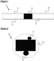
- a fibre, generally designated 10, according to a first aspect of the present invention, is shown schematically in Figures 1 and 2 .
- the fibre 10 comprises an electronic device 12, an electrical conductor 16, a reinforcing thread 18, and a resin body 20.
- the fibre 10 is in the region of 1m long.
- the electronic device 12 may be any appropriate electronic device, but in the present case is a temperature sensor 12.
- the temperature sensor 12 has a maximum dimension of 500 ⁇ m or 300 ⁇ m.
- the electrical conductor 16 is formed from copper wire, and is electrically connected to an appropriate contact point on the temperature sensor 12. The electrical conductor 16 extend across the entire length of the fibre 10, as shown in Figure 1 .
- the reinforcing thread 18 is attached to the temperature sensor 12, and extends across the entire length of the fibre 10, as shown in Figure 1 .
- the reinforcing thread 18 may be formed of any material sufficient to reinforce the fibre 10, and in the present case is formed from nylon.
- the resin body 20 encapsulates each of the temperature sensor 12, the electrical conductor 16, and the reinforcing thread 18, such that the resin body 20 forms an outermost layer of the fibre 10. In this manner, the resin body 20 prevents exposure of the remaining components to the external environment of the fibre 10. Furthermore, and as seen in Figure 1 , the resin body 20 forms a main body of the fibre 10 along the length of the fibre 10.
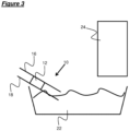
- a method of manufacturing the fibre 10 is shown schematically in Figure 3 .
- the electrical conductor 16 and the reinforcing thread 18, are connected to the temperature sensor 12.
- This combined structure is dipped into a resin bath 22, and subsequently passed to a curing station 24.
- the curing station 24 utilises a suitable form of curing, for example applying heat, UV light, or hot air, to cure the resin, thereby forming the resin body 20.
- first 10 and second 10' fibres are attached to fabric tape or ribbon 26.
- One side of the fabric tape that is not contact with skin of a user is provided with a thermally insulating material (not-shown) in the region of the temperature sensors 12, 12' of the first 10 and second 10' fibres.
- the first 10 and second 10' fibres are provided at one end with a connection member 28, for connection to a Bluetooth transmitting device 32.
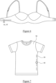
- the fabric tape 26 is attached to the inside of a underwear t-shirt 30, such that the thermally insulating material contacts the fabric of the t-shirt 30, and the temperature sensors 12,12' are exposed to the interior of the t-shirt 30.
- the first 10 and second 10' fibres are connected to a Bluetooth transmitting device 32 via the connection member 28.
- the temperature sensors 12, 12' are able to sense the temperature of the body of the wearer, and are able to relay this information to a remote monitoring location via the Bluetooth transmitting device 32.
- FIG. 6 Another embodiment of a garment incorporating the first 10 and second 10' fibres is shown schematically in Figure 6 .
- the garment is a bra, which incorporates the first 10 and second 10' fibres in a similar manner to the t-shirt 30 shown in Figure 5 .
- the fibre 10 of the present invention may be used to provide real time feedback of an athlete's performance and/or body vitals.
- the fibre 10 of the present invention may be incorporated into a garment intended to be worn by an infant.
- the body temperature of the infant may be monitored using fibres according to the present invention, and relevant data can be transmitted to, for example, a parent, or a clinician. In such a manner, rises or falls in the body temperature of the infant can be immediately notified to the relevant persons, such that the relevant person can then take action should such action be necessary.
- the fibre 10 may be used in a garment for adults and/or elderly patients in a similar manner.
- FIG. 7 A further embodiment of a garment incorporating a fibre according to the present invention is shown in Figure 7 .
- the garment 36 is a t-shirt 36, which has a fibre 38 sewn into its side seam.
- the fibre 38 differs from the fibres 10, 10' previously discussed, in that the fibre 38 has an RFID sensor 40 instead of a temperature sensor 12,12'.
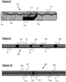
- the fibre 100 comprises an electronic device 102, first 104 and second 106 electrical conductors, a reinforcing thread 108, a resin body 110, and first 112 and second 114 electrical connectors.
- the electronic device 102 may be any appropriate electronic device, but in the present case is a temperature sensor 12.
- the first 104 and second 106 electrical conductors are formed from copper wire, and are electrically connected to the first 112 and second 114 electrical connectors of the temperature sensor 102.
- the first 104 and second 106 electrical conductors extend across the entire length of the fibre 100, as shown in Figure 8 .
- the reinforcing thread 108 extends across the entire length of the fibre 100, as shown in Figure 8 .
- the reinforcing thread 108 may be formed of any material sufficient to reinforce the fibre 100, and in the present case is formed from nylon.
- the first 104 and second 106 electrical conductors are wound around the reinforcing thread 108 in a helical manner.
- the resin body 110 encapsulates each of the temperature sensor 102, the first 104 and second 106 electrical conductors, the reinforcing thread 108, and the first 112 and second 114 electrical connectors such that the resin body 110 forms an outermost layer of the fibre 100. In this manner, the resin body 110 prevents exposure of the remaining components to the external environment of the fibre 100. Furthermore, and as seen in Figure 8 , the resin body 110 forms a main body of the fibre 100 along the length of the fibre 100.
- the third embodiment of the fibre 200 is substantially the same as the first embodiment 10, and differs only in that the fibre 200 has a plurality of different electronic devices 202,204,206,208 encapsulated therein.
- a fourth embodiment of a fibre according to the present invention, generally designated 300, is shown schematically in Figure 10 .
- the fibre 300 comprises an electronic device 302, first 304 and second 306 electrical conductors, a reinforcing thread 308, and first 310, second 312, third 314, and fourth 316 resin bodies.
- the electronic device 302 in the fourth embodiment is an RFID tag.
- the first 304 and second 306 electrical conductors are formed from copper wire, and are electrically connected to the RFID tag 302.
- the first 304 and second 306 electrical conductors extend across the entire length of the fibre 300, as shown in Figure 10 .
- the reinforcing thread 308 extends across the entire length of the fibre 300, as shown in Figure 10 .
- the reinforcing thread 308 may be formed of any material sufficient to reinforce the fibre 300, and in the present case is formed from nylon.
- the first resin body 310 is formed of epoxy resin and encapsulates the RFID tag 302, along with portions of the first 304 and second 306 electrical conductors, and a portion of the reinforcing thread 308.
- the use of epoxy resin for the first resin body 310 may be beneficial as it may provide a region of relatively high structural strength about the RFID tag 302.
- the second 312 and third 314 resin bodies are formed of an electrically insulating resin, and encapsulate the remainder of the first 304 and second 306 electrical conductors and the reinforcing thread 308 either side of the RFID tag 302.
- the fourth resin body 316 encapsulates the first 310, second 312, and third 314 resin bodies, such that the fourth resin body 314 defines an outer layer of the fibre 300, and is formed from a resin which is more flexible than the resin of the first 310, second 312, and third 314 bodies of resin, for example polyurethane or silicone elastomer.
- first 310, second 312, third 314 and fourth 316 bodies of resin may allow resins having different material properties, eg structural strength, flexibility, heat/electrical conduction, to be chosen dependent on the application of the fibre 300, whilst still ensuring that the electronic device (eg the RFID tag 302) and the electrical conductors 304,306 are encapsulated, thereby preventing exposure to ambient conditions.
- resins having different material properties eg structural strength, flexibility, heat/electrical conduction
- a fifth embodiment of a fibre according to the present invention is shown schematically in Figure 11 .
- the fifth embodiment of the fibre is substantially identical to the fourth embodiment of the fibre 300, and hence the reference numerals used for the fourth and fifth embodiments of the fibre 300 are the same.
- the fifth embodiment differs from the fourth embodiment only in that the fourth resin body 316 in the region of the RFID tag 302 is thicker relative to the remaining regions of the fourth resin body 316 along the length of the fibre 300. This region of increased thickness may, for example provide increased thermal resistance or increased mechanical strength in the region of the RFID 302.
Landscapes
- Engineering & Computer Science (AREA)
- Mechanical Engineering (AREA)
- Textile Engineering (AREA)
- Woven Fabrics (AREA)
- Laminated Bodies (AREA)
- Chemical Or Physical Treatment Of Fibers (AREA)
Claims (14)
- Faser (100) zur Einarbeitung in eine Textilie, wobei die Faser (100) eine elektronische Vorrichtung (102) und einen elektrischen Leiter (104, 106) umfasst, der mit der elektronischen Vorrichtung (102) verbunden ist und sich entlang der gesamten Längsachse der Faser (100) erstreckt, wobei die elektronische Vorrichtung (102) und der elektrische Leiter (104, 106) von einem einheitlichen Körper (110) aus mindestens einem ersten Material umhüllt sind, und wobei die Faser (100) ein Verstärkungselement (108) zum Verstärken der Faser (100) umfasst und der elektrische Leiter (104, 106) um das Verstärkungselement (108) gewickelt ist.
- Faser (100) nach Anspruch 1, wobei das erste Material sowohl die elektronische Vorrichtung (102) als auch den elektrischen Leiter (104, 106) umhüllt oder das erste Material die elektronische Vorrichtung (102) umhüllt, die als einzelner Körper an ein zweites Material gebunden ist, das den Leiter (104, 106) umhüllt.
- Faser (100) nach Anspruch 1, wobei der einheitliche Körper (110) eine Vielzahl von Materialien in einer geschichteten Struktur (310, 312, 314, 316) umfasst.
- Faser (100) nach einem der vorhergehenden Ansprüche, wobei der einheitliche Körper (110) eine innere Schicht aus mindestens dem ersten Material (310), die mit der elektronischen Vorrichtung (302) und/oder dem Leiter (304, 306) in Kontakt steht, und eine äußere Schicht (316) umfasst, die sich um die innere Schicht erstreckt.
- Faser (100) nach Anspruch 4, wobei die innere Schicht dazu angepasst ist, die elektronische Vorrichtung (302) und/oder den Leiter (304, 306) zu schützen, und im Vergleich zu der äußeren Schicht eine größere Steifigkeit, einen größeren Wärmewiderstand und/oder einen größeren elektrischen Widerstand aufweist.
- Faser (100) nach Anspruch 4 oder Anspruch 5, wobei das Material der äußeren Schicht ein Material ist, das im Vergleich zu der inneren Schicht eine von Natur aus größere Flexibilität aufweist.
- Faser (100) nach einem der Ansprüche 4 bis 6, wobei das Material der inneren Schicht mindestens durchscheinend oder transparent ist.
- Faser (100) nach einem der vorhergehenden Ansprüche, wobei das Verstärkungselement (108) einen Faden umfasst, der sich entlang der Längsachse der Faser (100) erstreckt.
- Faser (100) nach einem der vorhergehenden Ansprüche, wobei das erste Material ein Harz umfasst.
- Faser (100) nach einem der vorhergehenden Ansprüche, wobei die Faser (100) eine Vielzahl von elektronischen Vorrichtungen (202, 204, 206, 208) umfasst, wobei jede der Vielzahl von elektronischen Vorrichtungen (202, 204, 206, 208) mit mindestens einem elektrischen Leiter verbunden ist, wobei die Vielzahl von elektronischen Vorrichtungen (202, 204, 206, 208) und die elektrischen Leiter (104, 106) von dem einheitlichen Körper (110) aus mindestens einem ersten Material umhüllt sind.
- Faser (100) nach Anspruch 10, wobei die elektrischen Leiter (104, 106) über die gesamte Länge der elektrischen Leiter (104, 106) von dem einheitlichen Körper (110) aus mindestens einem ersten Material umhüllt sind.
- Textilie, die eine Faser (100) nach einem der vorhergehenden Ansprüche eingearbeitet hat.
- Verfahren zum Herstellen einer Faser (100) zur Einarbeitung in eine Textilie, wobei das Verfahren Verbinden eines elektrischen Leiters (104, 106) mit einer elektronischen Vorrichtung (102), Wickeln des elektrischen Leiters (104, 106) um ein Verstärkungselement (108) und Umhüllen der elektronischen Vorrichtung (102) und des elektrischen Leiters (104, 106) in einem einheitlichen Körper (110) aus mindestens einem ersten Material, sodass sich der elektrische Leiter (104, 106) entlang der gesamten Längsachse der Faser (100) erstreckt, umfasst.
- Verfahren zum Herstellen einer Textilie, wobei das Verfahren Einarbeiten einer Faser (100) nach einem der Ansprüche 1 bis 11 in die Textilie umfasst.
Applications Claiming Priority (2)
| Application Number | Priority Date | Filing Date | Title |
|---|---|---|---|
| GB201605925 | 2016-04-07 | ||
| PCT/GB2017/050980 WO2017175001A1 (en) | 2016-04-07 | 2017-04-07 | Improvements relating to textiles incorporating electronic devices |
Publications (3)
| Publication Number | Publication Date |
|---|---|
| EP3440246A1 EP3440246A1 (de) | 2019-02-13 |
| EP3440246C0 EP3440246C0 (de) | 2024-11-27 |
| EP3440246B1 true EP3440246B1 (de) | 2024-11-27 |
Family
ID=58548758
Family Applications (1)
| Application Number | Title | Priority Date | Filing Date |
|---|---|---|---|
| EP17717842.3A Active EP3440246B1 (de) | 2016-04-07 | 2017-04-07 | Verbesserungen im zusammenhang mit textilien mit elektronischen vorrichtungen |
Country Status (8)
| Country | Link |
|---|---|
| US (1) | US10954611B2 (de) |
| EP (1) | EP3440246B1 (de) |
| CN (1) | CN109689955B (de) |
| AU (1) | AU2017245894B2 (de) |
| ES (1) | ES3014393T3 (de) |
| GB (1) | GB2561490B (de) |
| PL (1) | PL3440246T3 (de) |
| WO (1) | WO2017175001A1 (de) |
Families Citing this family (15)
| Publication number | Priority date | Publication date | Assignee | Title |
|---|---|---|---|---|
| EP3389482A4 (de) | 2015-12-16 | 2019-05-08 | Siren Care, Inc. | System und verfahren zum nachweis einer entzündung in einem fuss |
| US10954611B2 (en) | 2016-04-07 | 2021-03-23 | Adetexs Ltd | Relating to textiles incorporating electronic devices |
| US10557220B2 (en) | 2016-09-27 | 2020-02-11 | Siren Care, Inc. | Smart yarn and method for manufacturing a yarn containing an electronic device |
| TWI760401B (zh) * | 2017-12-15 | 2022-04-11 | 財團法人紡織產業綜合研究所 | 導電紗線模組 |
| FR3078980B1 (fr) * | 2018-03-14 | 2021-06-11 | Primo1D | Fil guipe compose d’une ame principale et d’au moins un fils de couverture et comprenant au moins un element filaire conducteur relie electriquement a au moins une puce electronique |
| US11233012B2 (en) | 2018-03-19 | 2022-01-25 | Apple Inc. | Fabric-based items having strands with embedded components |
| DE102018114465A1 (de) * | 2018-06-15 | 2019-12-19 | Osram Opto Semiconductors Gmbh | Optoelektronische faser sowie vorrichtung und verfahren zur herstellung einer optoelektronischen faser |
| WO2020118694A1 (en) | 2018-12-14 | 2020-06-18 | Siren Care, Inc. | Temperature-sensing garment and method for making same |
| CN109554797B (zh) * | 2019-01-29 | 2022-08-12 | 香港理工大学 | 一种微电子纱线及其制备方法 |
| IL297505B2 (en) * | 2020-04-24 | 2025-11-01 | Advanced Functional Fabrics Of America Inc | Multi-material fibers and methods of manufacturing the same |
| EP4139509B1 (de) * | 2020-04-24 | 2024-06-05 | Advanced Functional Fabrics Of America, Inc. | Mehrmaterialfasern und verfahren zu deren herstellung |
| WO2022158474A1 (ja) * | 2021-01-19 | 2022-07-28 | ベジ 佐々木 | 電子装置及び製品 |
| DE102021114931A1 (de) | 2021-06-10 | 2022-12-15 | Voith Patent Gmbh | Walzenmantel mit Beschädigungsfrüherkennung |
| EP4359363A4 (de) * | 2021-06-21 | 2025-05-07 | Free Form Fibers, LLC | Faserstrukturen mit eingebetteten sensoren |
| FR3150613B1 (fr) * | 2023-06-30 | 2025-12-12 | Primo1D | Dispositif d'émission-réception radiofréquence comprenant un fil conducteur formant antenne enroule en spires |
Citations (2)
| Publication number | Priority date | Publication date | Assignee | Title |
|---|---|---|---|---|
| WO2009004243A2 (fr) | 2007-06-21 | 2009-01-08 | Commissariat A L'energie Atomique | Assemblage de puces radiofrequence |
| GB2472026A (en) | 2009-07-21 | 2011-01-26 | Univ Manchester | Signalling device |
Family Cites Families (45)
| Publication number | Priority date | Publication date | Assignee | Title |
|---|---|---|---|---|
| GB252900A (en) | 1925-06-04 | 1926-06-10 | Violet Cornelia Koop | Improvements in or relating to the construction of work baskets, and the like |
| GB900519A (en) * | 1957-07-08 | 1962-07-04 | Eisler Paul | Electric conductor strips |
| FR2186923A5 (de) * | 1970-07-09 | 1974-01-11 | Spirotechnique | |
| JPH05274082A (ja) | 1992-03-25 | 1993-10-22 | Clarion Co Ltd | ペン型座標入力装置 |
| EP0954836B1 (de) * | 1997-01-25 | 2004-03-31 | Philip Noel Leonard | Identifizierungs- oder kontrollanordnung |
| BR9804917A (pt) | 1997-05-19 | 2000-01-25 | Hitachi Maxell Ltda | Módulo de circuito integrado flexìvel e processos para produzir um módulo de circuito integrado flexìvel e um portador de informação. |
| FR2793069B1 (fr) | 1999-04-28 | 2003-02-14 | Gemplus Card Int | Procede de fabrication de dispositif electronique portable a circuit integre protege par resine photosensible |
| GB0108950D0 (en) * | 2001-04-10 | 2001-05-30 | Leonard Philip N | Personal computer systems |
| US7845022B1 (en) | 2002-02-14 | 2010-12-07 | Nike, Inc. | Deposition of electronic circuits on fibers and other materials |
| US7592276B2 (en) * | 2002-05-10 | 2009-09-22 | Sarnoff Corporation | Woven electronic textile, yarn and article |
| AU2003279888A1 (en) * | 2002-06-28 | 2004-01-19 | North Carolina State University | Fabric and yarn structures for improving signal integrity in fabric based electrical circuits |
| DE10333583A1 (de) * | 2003-02-18 | 2004-09-30 | Textilforschungsinstitut Thüringen-Vogtland e.V. (TITV e.V.) | Textile Flächenstruktur aus einer Anordnung einer Vielzahl von leitfähigen oder leitfähige Eigenschaften aufweisenden Fäden sowie Verfahren zu deren Herstellung |
| CN1984770B (zh) * | 2004-06-18 | 2011-04-20 | 特克斯特龙尼克斯公司 | 功能性弹性纺织结构 |
| GB2426255B (en) | 2005-05-16 | 2009-09-23 | Univ Manchester | Operative devices |
| US20070089800A1 (en) * | 2005-10-24 | 2007-04-26 | Sensatex, Inc. | Fabrics and Garments with Information Infrastructure |
| TWI281357B (en) | 2005-12-28 | 2007-05-11 | Taiwan Textile Res Inst | Conductive heating device |
| CN101384186B (zh) * | 2006-02-15 | 2012-07-18 | 皇家飞利浦电子股份有限公司 | 织物和电子部件的结构 |
| CN101221037A (zh) | 2007-01-11 | 2008-07-16 | 柳州欧维姆机械股份有限公司 | 纤维增强树脂筋封装电阻应变计 |
| JP5274082B2 (ja) | 2008-04-08 | 2013-08-28 | 天龍コンポジット株式会社 | 繊維強化樹脂製コア |
| CN102912510A (zh) | 2008-05-28 | 2013-02-06 | 瑟尔瑞株式会社 | 导电垫及其制造方法 |
| GB2472025A (en) | 2009-07-21 | 2011-01-26 | Univ Manchester | Identification device |
| DE102009052929B4 (de) * | 2009-11-12 | 2011-12-08 | Kunert Fashion Gmbh & Co. Kg | Strickware mit Feuchtigkeitssensor |
| FR2955972B1 (fr) * | 2010-02-03 | 2012-03-09 | Commissariat Energie Atomique | Procede d'assemblage d'au moins une puce avec un tissu incluant un dispositif a puce |
| TW201144503A (en) * | 2010-06-09 | 2011-12-16 | Kings Metal Fiber Technologies | Conducting yarn, yarn circuit and fabric circuit board |
| FR2961947B1 (fr) * | 2010-06-24 | 2013-03-15 | Commissariat Energie Atomique | Incorporation d'elements a puce dans un fil guipe |
| CN102002791B (zh) * | 2010-11-29 | 2011-09-28 | 武汉纺织大学 | 一种感触电子织物 |
| JP5715835B2 (ja) | 2011-01-25 | 2015-05-13 | 新光電気工業株式会社 | 半導体パッケージ及びその製造方法 |
| JP5994077B2 (ja) * | 2012-03-13 | 2016-09-21 | 福井県 | 複合糸及びそれを用いた布帛並びに複合糸の製造方法 |
| CN104937151B (zh) * | 2012-11-24 | 2018-07-03 | 健康监测有限公司 | 竖直导电纺织迹线及其编织(knitting)方法 |
| JP6264825B2 (ja) | 2013-10-18 | 2018-01-24 | ヤマハ株式会社 | 歪みセンサ付き布帛及び被服 |
| DE202014100158U1 (de) * | 2014-01-15 | 2014-02-25 | King's Metal Fiber Technologies Co., Ltd. | Gewebeanordnung |
| DE102014103978A1 (de) * | 2014-03-24 | 2015-09-24 | Ditf Deutsche Institute Für Textil- Und Faserforschung Stuttgart | Sensorgarn |
| GB2529900B (en) * | 2014-09-08 | 2017-05-03 | Univ Nottingham Trent | Electronically functional yarns |
| EP3231477B1 (de) | 2014-12-12 | 2021-03-24 | Woo, Dae-Ki | Am körper tragbares band für niederfrequenztherapie |
| FR3034614A1 (fr) | 2015-04-03 | 2016-10-07 | Linxens Holding | Procede de fabrication d’un circuit flexible, circuit flexible obtenu par ce procede et carte a puce comportant un tel circuit flexible |
| FR3038210A1 (fr) | 2015-07-02 | 2017-01-06 | Eolane Combree | Procede de solidarisation d'un dispositif electronique sur une piece textile et de connexion electrique dudit dispositif electronique a au moins un fil electrique insere dans ladite piece textile. |
| FR3038919B1 (fr) | 2015-07-13 | 2018-11-09 | Ets A. Deschamps Et Fils | Procede et machine de fabrication d'une structure tissee |
| FR3042203B1 (fr) * | 2015-10-12 | 2018-06-22 | Commissariat A L'energie Atomique Et Aux Energies Alternatives | Incorporation d'elements a puce dans un fil guipe. |
| KR101798192B1 (ko) | 2015-12-14 | 2017-11-15 | 한국신발피혁연구원 | 전기전도성이 우수한 코팅사 제조방법 및 이를 이용한 습도센서의 제조방법 |
| GB201523093D0 (en) * | 2015-12-30 | 2016-02-10 | Univ Nottingham Trent | Electronic strip yarn |
| US10954611B2 (en) | 2016-04-07 | 2021-03-23 | Adetexs Ltd | Relating to textiles incorporating electronic devices |
| US10492302B2 (en) | 2016-05-03 | 2019-11-26 | Google Llc | Connecting an electronic component to an interactive textile |
| US10557220B2 (en) * | 2016-09-27 | 2020-02-11 | Siren Care, Inc. | Smart yarn and method for manufacturing a yarn containing an electronic device |
| TWI752106B (zh) * | 2016-10-28 | 2022-01-11 | 日商帝人股份有限公司 | 用於壓電元件之構造體、編織狀壓電元件、使用編織狀壓電元件之布帛狀壓電元件及使用該些之裝置 |
| KR20180049558A (ko) * | 2016-11-03 | 2018-05-11 | 한국과학기술연구원 | 섬유형 트랜지스터 및 이의 제조 방법 |
-
2017
- 2017-04-07 US US16/091,122 patent/US10954611B2/en active Active
- 2017-04-07 GB GB1810117.0A patent/GB2561490B/en active Active
- 2017-04-07 CN CN201780035339.7A patent/CN109689955B/zh not_active Expired - Fee Related
- 2017-04-07 ES ES17717842T patent/ES3014393T3/es active Active
- 2017-04-07 PL PL17717842.3T patent/PL3440246T3/pl unknown
- 2017-04-07 WO PCT/GB2017/050980 patent/WO2017175001A1/en not_active Ceased
- 2017-04-07 EP EP17717842.3A patent/EP3440246B1/de active Active
- 2017-04-07 AU AU2017245894A patent/AU2017245894B2/en not_active Ceased
Patent Citations (2)
| Publication number | Priority date | Publication date | Assignee | Title |
|---|---|---|---|---|
| WO2009004243A2 (fr) | 2007-06-21 | 2009-01-08 | Commissariat A L'energie Atomique | Assemblage de puces radiofrequence |
| GB2472026A (en) | 2009-07-21 | 2011-01-26 | Univ Manchester | Signalling device |
Non-Patent Citations (3)
| Title |
|---|
| "Doctoral Thesis, Nottingham Trent University", 1 October 2015, article SARATHCHANDRA RATHNAYAKE ANURA: "DEVELOPMENT OF THE CORE TECHNOLOGY FOR THE CREATION OF ELECTRONICALLY-ACTIVE, SMART YARN ", XP093310334 |
| ANONYMOUS: "Quelle est la différence entre une fibre et un filament ?", TEXTILEADDICT, 16 September 2016 (2016-09-16), XP093310332, Retrieved from the Internet <URL:https://textileaddict.me/quelle-est-la-difference-entre-une-fibre-et-un-filament/#:~:text=Le fil textile%2C qu'il,utilisable pour les fabrications textiles> |
| D2B - ANURA SARATHCHANDRA RATHNAYAKE: "IRepDevelopment of the core technology for the creation of electronically-active, smart yarn + Tools", 16 November 2016 (2016-11-16), Retrieved from the Internet <URL:https://irep.ntu.ac.uk/id/eprint/29140/> [retrieved on 20250719] |
Also Published As
| Publication number | Publication date |
|---|---|
| EP3440246C0 (de) | 2024-11-27 |
| US20200325602A1 (en) | 2020-10-15 |
| PL3440246T3 (pl) | 2025-04-07 |
| CN109689955A (zh) | 2019-04-26 |
| AU2017245894A1 (en) | 2018-11-22 |
| GB201810117D0 (en) | 2018-08-08 |
| WO2017175001A1 (en) | 2017-10-12 |
| US10954611B2 (en) | 2021-03-23 |
| ES3014393T3 (en) | 2025-04-22 |
| AU2017245894B2 (en) | 2022-12-01 |
| EP3440246A1 (de) | 2019-02-13 |
| CN109689955B (zh) | 2022-04-29 |
| GB2561490A (en) | 2018-10-17 |
| GB2561490B (en) | 2019-02-27 |
Similar Documents
| Publication | Publication Date | Title |
|---|---|---|
| AU2017245894B2 (en) | Improvements relating to textiles incorporating electronic devices | |
| US8701578B2 (en) | Digital garment using embroidery technology and fabricating method thereof | |
| JP3204003U (ja) | プラスチック糸改良構造 | |
| US10472742B1 (en) | Fabric-based items with fusible insulating strands | |
| CN110923897B (zh) | 具有电气部件的织物制品 | |
| KR20160148530A (ko) | 섬유를 사용한 전기 신호를 출력 또는 입력으로 하는 트랜스듀서 | |
| US10499502B2 (en) | Flexible device module for fabric layer assembly and method for production | |
| US11091855B2 (en) | Electronically functional yarn and textile | |
| US9932697B2 (en) | Structure and method for connecting fabric sensor and digital yarn | |
| WO2016195929A1 (en) | Insulated conductive strands with polymer cores | |
| US20180042368A1 (en) | Electronic Devices With Wrist Straps | |
| KR102144738B1 (ko) | 유연성 컴퓨팅 패브릭 | |
| Dias et al. | Integration of micro-electronics with yarns for smart textiles | |
| EP1882059B1 (de) | In fäden installierte betriebsfähige vorrichtungen | |
| KR101619515B1 (ko) | 도전성 패드 및 그 제조방법 | |
| CN110537190A (zh) | Rfid标签 | |
| KR101911911B1 (ko) | 신축성 도전성 원단 | |
| JP6932774B2 (ja) | 繊維製品およびその製造方法 | |
| HK40004444B (en) | Improvements relating to textiles incorporating electronic devices | |
| HK40004444A (en) | Improvements relating to textiles incorporating electronic devices | |
| JP2018015359A (ja) | 複合線材および手術用ガーゼ | |
| US20190156972A1 (en) | Electronic functional member, knitted product using the same, and method for manufacturing electronic functional member | |
| KR101615775B1 (ko) | 고강성을 갖는 발포폼 | |
| CN114830128B (zh) | 柔性抗水传感器标签 | |
| US20210079569A1 (en) | Forming Electrical Connections in Fabric-Based Items |
Legal Events
| Date | Code | Title | Description |
|---|---|---|---|
| STAA | Information on the status of an ep patent application or granted ep patent |
Free format text: STATUS: UNKNOWN |
|
| STAA | Information on the status of an ep patent application or granted ep patent |
Free format text: STATUS: THE INTERNATIONAL PUBLICATION HAS BEEN MADE |
|
| PUAI | Public reference made under article 153(3) epc to a published international application that has entered the european phase |
Free format text: ORIGINAL CODE: 0009012 |
|
| STAA | Information on the status of an ep patent application or granted ep patent |
Free format text: STATUS: REQUEST FOR EXAMINATION WAS MADE |
|
| 17P | Request for examination filed |
Effective date: 20181106 |
|
| AK | Designated contracting states |
Kind code of ref document: A1 Designated state(s): AL AT BE BG CH CY CZ DE DK EE ES FI FR GB GR HR HU IE IS IT LI LT LU LV MC MK MT NL NO PL PT RO RS SE SI SK SM TR |
|
| AX | Request for extension of the european patent |
Extension state: BA ME |
|
| DAV | Request for validation of the european patent (deleted) | ||
| DAX | Request for extension of the european patent (deleted) | ||
| REG | Reference to a national code |
Ref country code: HK Ref legal event code: DE Ref document number: 40004444 Country of ref document: HK |
|
| STAA | Information on the status of an ep patent application or granted ep patent |
Free format text: STATUS: EXAMINATION IS IN PROGRESS |
|
| 17Q | First examination report despatched |
Effective date: 20210611 |
|
| RAP3 | Party data changed (applicant data changed or rights of an application transferred) |
Owner name: ADETEXS LTD |
|
| GRAP | Despatch of communication of intention to grant a patent |
Free format text: ORIGINAL CODE: EPIDOSNIGR1 |
|
| STAA | Information on the status of an ep patent application or granted ep patent |
Free format text: STATUS: GRANT OF PATENT IS INTENDED |
|
| INTG | Intention to grant announced |
Effective date: 20230525 |
|
| GRAJ | Information related to disapproval of communication of intention to grant by the applicant or resumption of examination proceedings by the epo deleted |
Free format text: ORIGINAL CODE: EPIDOSDIGR1 |
|
| STAA | Information on the status of an ep patent application or granted ep patent |
Free format text: STATUS: EXAMINATION IS IN PROGRESS |
|
| GRAP | Despatch of communication of intention to grant a patent |
Free format text: ORIGINAL CODE: EPIDOSNIGR1 |
|
| STAA | Information on the status of an ep patent application or granted ep patent |
Free format text: STATUS: GRANT OF PATENT IS INTENDED |
|
| INTC | Intention to grant announced (deleted) | ||
| INTG | Intention to grant announced |
Effective date: 20240202 |
|
| GRAS | Grant fee paid |
Free format text: ORIGINAL CODE: EPIDOSNIGR3 |
|
| GRAA | (expected) grant |
Free format text: ORIGINAL CODE: 0009210 |
|
| STAA | Information on the status of an ep patent application or granted ep patent |
Free format text: STATUS: THE PATENT HAS BEEN GRANTED |
|
| AK | Designated contracting states |
Kind code of ref document: B1 Designated state(s): AL AT BE BG CH CY CZ DE DK EE ES FI FR GB GR HR HU IE IS IT LI LT LU LV MC MK MT NL NO PL PT RO RS SE SI SK SM TR |
|
| REG | Reference to a national code |
Ref country code: GB Ref legal event code: FG4D |
|
| REG | Reference to a national code |
Ref country code: CH Ref legal event code: EP |
|
| REG | Reference to a national code |
Ref country code: IE Ref legal event code: FG4D |
|
| REG | Reference to a national code |
Ref country code: DE Ref legal event code: R096 Ref document number: 602017086358 Country of ref document: DE |
|
| U01 | Request for unitary effect filed |
Effective date: 20241219 |
|
| U07 | Unitary effect registered |
Designated state(s): AT BE BG DE DK EE FI FR IT LT LU LV MT NL PT RO SE SI Effective date: 20250206 |
|
| PG25 | Lapsed in a contracting state [announced via postgrant information from national office to epo] |
Ref country code: IS Free format text: LAPSE BECAUSE OF FAILURE TO SUBMIT A TRANSLATION OF THE DESCRIPTION OR TO PAY THE FEE WITHIN THE PRESCRIBED TIME-LIMIT Effective date: 20250327 Ref country code: HR Free format text: LAPSE BECAUSE OF FAILURE TO SUBMIT A TRANSLATION OF THE DESCRIPTION OR TO PAY THE FEE WITHIN THE PRESCRIBED TIME-LIMIT Effective date: 20241127 |
|
| REG | Reference to a national code |
Ref country code: ES Ref legal event code: FG2A Ref document number: 3014393 Country of ref document: ES Kind code of ref document: T3 Effective date: 20250422 |
|
| PG25 | Lapsed in a contracting state [announced via postgrant information from national office to epo] |
Ref country code: NO Free format text: LAPSE BECAUSE OF FAILURE TO SUBMIT A TRANSLATION OF THE DESCRIPTION OR TO PAY THE FEE WITHIN THE PRESCRIBED TIME-LIMIT Effective date: 20250227 |
|
| PG25 | Lapsed in a contracting state [announced via postgrant information from national office to epo] |
Ref country code: RS Free format text: LAPSE BECAUSE OF FAILURE TO SUBMIT A TRANSLATION OF THE DESCRIPTION OR TO PAY THE FEE WITHIN THE PRESCRIBED TIME-LIMIT Effective date: 20250227 |
|
| REG | Reference to a national code |
Ref country code: GR Ref legal event code: EP Ref document number: 20250400444 Country of ref document: GR Effective date: 20250409 |
|
| PG25 | Lapsed in a contracting state [announced via postgrant information from national office to epo] |
Ref country code: SM Free format text: LAPSE BECAUSE OF FAILURE TO SUBMIT A TRANSLATION OF THE DESCRIPTION OR TO PAY THE FEE WITHIN THE PRESCRIBED TIME-LIMIT Effective date: 20241127 |
|
| PG25 | Lapsed in a contracting state [announced via postgrant information from national office to epo] |
Ref country code: SK Free format text: LAPSE BECAUSE OF FAILURE TO SUBMIT A TRANSLATION OF THE DESCRIPTION OR TO PAY THE FEE WITHIN THE PRESCRIBED TIME-LIMIT Effective date: 20241127 |
|
| PG25 | Lapsed in a contracting state [announced via postgrant information from national office to epo] |
Ref country code: CZ Free format text: LAPSE BECAUSE OF FAILURE TO SUBMIT A TRANSLATION OF THE DESCRIPTION OR TO PAY THE FEE WITHIN THE PRESCRIBED TIME-LIMIT Effective date: 20241127 |
|
| PLBI | Opposition filed |
Free format text: ORIGINAL CODE: 0009260 |
|
| PLAX | Notice of opposition and request to file observation + time limit sent |
Free format text: ORIGINAL CODE: EPIDOSNOBS2 |
|
| 26 | Opposition filed |
Opponent name: PRIMO1D Effective date: 20250826 |
|
| REG | Reference to a national code |
Ref country code: CH Ref legal event code: H13 Free format text: ST27 STATUS EVENT CODE: U-0-0-H10-H13 (AS PROVIDED BY THE NATIONAL OFFICE) Effective date: 20251125 |
|
| U90 | Renewal fees not paid: noting of loss of rights |
Free format text: RENEWAL FEE NOT PAID FOR YEAR 09 Effective date: 20251118 |
|
| PG25 | Lapsed in a contracting state [announced via postgrant information from national office to epo] |
Ref country code: MC Free format text: LAPSE BECAUSE OF FAILURE TO SUBMIT A TRANSLATION OF THE DESCRIPTION OR TO PAY THE FEE WITHIN THE PRESCRIBED TIME-LIMIT Effective date: 20241127 |
|
| GBPC | Gb: european patent ceased through non-payment of renewal fee |
Effective date: 20250407 |
|
| PG25 | Lapsed in a contracting state [announced via postgrant information from national office to epo] |
Ref country code: GB Free format text: LAPSE BECAUSE OF NON-PAYMENT OF DUE FEES Effective date: 20250407 |
|
| PG25 | Lapsed in a contracting state [announced via postgrant information from national office to epo] |
Ref country code: GR Free format text: LAPSE BECAUSE OF NON-PAYMENT OF DUE FEES Effective date: 20251110 |
|
| PLBB | Reply of patent proprietor to notice(s) of opposition received |
Free format text: ORIGINAL CODE: EPIDOSNOBS3 |
|
| PG25 | Lapsed in a contracting state [announced via postgrant information from national office to epo] |
Ref country code: CH Free format text: LAPSE BECAUSE OF NON-PAYMENT OF DUE FEES Effective date: 20250430 |
|
| PG25 | Lapsed in a contracting state [announced via postgrant information from national office to epo] |
Ref country code: CY Free format text: LAPSE BECAUSE OF NON-PAYMENT OF DUE FEES Effective date: 20250407 |
|
| U93 | Unitary patent lapsed |
Free format text: RENEWAL FEE NOT PAID Effective date: 20250430 |
|
| PG25 | Lapsed in a contracting state [announced via postgrant information from national office to epo] |
Ref country code: IE Free format text: LAPSE BECAUSE OF NON-PAYMENT OF DUE FEES Effective date: 20250407 |