EP1882059B1 - In fäden installierte betriebsfähige vorrichtungen - Google Patents
In fäden installierte betriebsfähige vorrichtungen Download PDFInfo
- Publication number
- EP1882059B1 EP1882059B1 EP06779056A EP06779056A EP1882059B1 EP 1882059 B1 EP1882059 B1 EP 1882059B1 EP 06779056 A EP06779056 A EP 06779056A EP 06779056 A EP06779056 A EP 06779056A EP 1882059 B1 EP1882059 B1 EP 1882059B1
- Authority
- EP
- European Patent Office
- Prior art keywords
- filaments
- yarn
- around
- filament
- length
- Prior art date
- Legal status (The legal status is an assumption and is not a legal conclusion. Google has not performed a legal analysis and makes no representation as to the accuracy of the status listed.)
- Expired - Lifetime
Links
Images
Classifications
-
- D—TEXTILES; PAPER
- D02—YARNS; MECHANICAL FINISHING OF YARNS OR ROPES; WARPING OR BEAMING
- D02G—CRIMPING OR CURLING FIBRES, FILAMENTS, THREADS, OR YARNS; YARNS OR THREADS
- D02G3/00—Yarns or threads, e.g. fancy yarns; Processes or apparatus for the production thereof, not otherwise provided for
- D02G3/44—Yarns or threads characterised by the purpose for which they are designed
- D02G3/441—Yarns or threads with antistatic, conductive or radiation-shielding properties
-
- D—TEXTILES; PAPER
- D02—YARNS; MECHANICAL FINISHING OF YARNS OR ROPES; WARPING OR BEAMING
- D02G—CRIMPING OR CURLING FIBRES, FILAMENTS, THREADS, OR YARNS; YARNS OR THREADS
- D02G3/00—Yarns or threads, e.g. fancy yarns; Processes or apparatus for the production thereof, not otherwise provided for
- D02G3/22—Yarns or threads characterised by constructional features, e.g. blending, filament/fibre
- D02G3/40—Yarns in which fibres are united by adhesives; Impregnated yarns or threads
- D02G3/404—Yarns or threads coated with polymeric solutions
-
- D—TEXTILES; PAPER
- D10—INDEXING SCHEME ASSOCIATED WITH SUBLASSES OF SECTION D, RELATING TO TEXTILES
- D10B—INDEXING SCHEME ASSOCIATED WITH SUBLASSES OF SECTION D, RELATING TO TEXTILES
- D10B2401/00—Physical properties
- D10B2401/18—Physical properties including electronic components
Definitions
- This invention relates to operative devices and their incorporation in yarns. It relates particularly to the provision of protection for such devices for use in situations in which they would be vulnerable to damage.
- the invention also provides means by which operative devices may be readily incorporated into every day items and particularly fabric products.
- Operative devices such as silicon chips have application in many areas and can be used as sensors and processors of useful information, and transmitters of such information or data. They can be used in RF tagging; position and movement sensors; strain sensors; pressure sensors and signal processors. It is known to fit them in clothing products to monitor movements or characteristics of the wearer.
- the present invention is directed specifically at the installation of an operative device within a length of a multi-filament or multi-fibre yarn.
- the term "filament” is used herein to encompass both filaments and fibres in yarns of this type.
- the yarn may, consist of natural and/or synthetic filaments (or fibres).
- the device can be confined in such a yarn by separating the filaments of the yarn, and installing the device therein with the filaments spread around it.
- filaments of the yarn form a capsule around the device, which capsule comprises the filaments and a resin cured therebetween.
- operative devices in a yarn can be conducted in a pultrusion process, with a series of devices being installed seriatim in the same length of yarn.
- the devices can have conductors connected to them, which conductors can also become part of the yarn or filaments of the yarn. Thus, not only is the device confined within the yarn, but connected conductors can also become an integral part of the yarn construction.
- the operative device itself can take any suitable form, including electronic, such as a piezzoelectric crystal device or a silicon chip referred to above; magnetic (including ferro-magnetic and paramagnetic); optical, providing reflective or generated light signals, or showing symbols such as bar codes; and thermal to generate a signal upon heating or cooling.
- the device can also respond chemically to an external or internal influence, rendering the invention useful in pharmaceutical and cosmetic applications.
- a plurality of filaments are delivered centripetally to a central axis, and then drawn along that central axis.
- An operative device is delivered to the conjoining filaments at the axis to install the device between the filaments are the filaments are drawn along the axis.
- This method can be carried out as a continuous process with operative devices being delivered seriatim such that they are installed in successive lengths of yarn drawn along the axis.
- Resin can be delivered continuously to the central axis, or intermittently with each operative device, to secure and protest the device when it is confined within the yarn.
- the method described above can be readily adapted to form first and second layers of filaments around the device by delivering a further plurality of filaments to the central axis defined by the already formed multi-filament yarn. They can be drawn into and around the yarn with or without resin as required. It is also possible to install a shock-absorbing layer around the first filament layer, which is held in place by the second filament layer formed in this second stage.
- Apparatus for carrying out the method of the invention typically comprises supplies of individual filaments disposed around a central aperture to deliver filaments thereto; a mechanism for delivering operative devices to the central aperture; and means for drawing yarn formed from said filaments from the central aperture.
- the supplies of filaments may be mounted on a carousel having an axis coincident with the central aperture. It can include supplies of additional filaments disposed around the path of yarn drawn from the aperture to deliver yarn to the path and create an additional layer of filaments around yarn drawn from the central aperture. These can be mounted on a further carousel with a central aperture aligned with that of the first.
- the operative device within a length of yarn according to the invention is confined within a capsule around the device and comprising the yarn fibres and/or filaments.
- a capsule can be sealed around the device and at both ends to provide complete protection for the device.
- the resin of the capsule can also be cured around the device.
- Adjacent filaments of the yarn may be bonded to each other around the the device. It is also possible to create first and second layers of filaments around the device, possibly with a shock-absorbing layer between them using for example, the method outlined above.
- one or more devices according to the invention can be encapsulated in a single length of yarn, and the yarn can be used in various forms of fabric including knitted, braided, stitch bonded and woven fabrics.
- a central processor or power source spaced from the electronic device itself can be readily connected thereto along those conductors.
- a the device may provide its own power source. Depending upon its load requirements, it may be able to generate sufficient power either from ambient light or heat, or movement. If a device is being used to monitor adjacent movement or ambient variations, then its power requirements may be very low indeed.
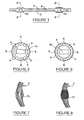
- Figure 1 illustrates a notional length of yarn with two operative devices installed at different locations therealong.
- the yarn 2 is a multi filament yarn comprising fibre and conductive filaments 4, 6.
- Each electronic device does, of course, create an expanded section of yarn, and although this will be evident in the yarn, it would not be inconsistent with some yarns used in various fabrics. Accordingly, in many fabrics the presence of anything unusual in the constituent yarns will not be readily apparent.
- Typical yarn diameters around a device will be of the order of 1mm using filaments of approximately 0.15 mm diameter.
- the volume of a typical device to be installed will be less than 0.5 mm 3 .
- the shape of the device is not critical, but it is normally rectanguloid, cylindrical or spherical. Spherical devices of diameter as little as 0.5 mm are contemplated.
- Figure 2 illustrates how the filaments in the yarn can be distributed around the device to confine it within the yarn. It also shows how the conductive filaments and fibre filaments are distributed. As can be seen four conductive filaments 6 are located at opposite ends of perpendicular diameters in the yarn cross-section, with two fibre filaments 4 located therebetween. Resin 8 is cast within the volume defined by the filaments 4 and 6, and around the electronic device or chip 10.
- the resin will normally be a polymer resin such as polyester or polyurethane resin; and the fibre filaments polyester or polyamide.
- the conductive filaments will normally be metal filament wires in the form of a polymeric monofilament yarn with either a copper or silver metal core wire.
- the cured resin 8 provides a solid casing and protection for the chip 10, which is sealed not only around the chip towards the yarn surface, but also at its ends within the yarn.
- the resin thus forms a solid capsule which provides effective protection for the chip even when the yarn in which it is confined is subject to the inevitable rigours of flexure during use, and particularly if used to form part of a fabric; thermal stress of the kind to which it will be subject during post processing and washing, and physical damage arising from contact with other bodies.
- Figure 3 illustrates an alternative technique for confining and protecting an electronic device confined between the filaments of a multi filament yarn.
- conductive filaments 6 are located as they are in Figure 2 , at the opposite end of perpendicular diameters.
- three fibre filaments 4 are shown between adjacent conductive filament 6. The reason for this is to ensure that adjacent filaments are in proper contact. Heat is applied to the filaments in a carefully controlled manner to soften and then melt abutting external sections of filament so that a bond is created when the fibres are allowed to cool. Using heat to create these thermal bonds has the benefit of interfering less directly with the enclosed chip 10, but does, of course, expose the chip to heat.
- Figure 4 shows how two layers of filaments can be arranged around an operative device in a multi-filament yarn.
- a group of inner filaments 12 creates a first protective layer around an operative device 14 within a mass of resin 16 in a manner similar to the arrangements described above with reference to Figures 2 and 3 .
- Outer filaments 18 form a second layer around the first layer, and in the arrangement shown a shock-absorbing layer 20 is interposed between the first and second layers.
- the use of two separate layers of filaments enables the inner layer to provide protection for the operative device.
- the outer layer as well as providing some additional protection, can serve to identify the nature of the confined device 14, for example by being colour coded.
- the shock-absorbing layer 20 is not essential to the arrangement of Figure 4 , and can be omitted. However, by providing what can be a relatively stiff shell around the protective device, it enables the use of a softer resin encapsulating the device 14, and this can be of value in some circumstances.
- the layer 20 is typically a ring pre-formed from a length of plastics tube, itself reinforced by auxiliary filaments 22. These auxiliary filaments can be glass fibre filaments, but metal filaments could also be used, depending upon the nature of the operative device 14 and the influence they might have on its function.
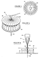
- Figures 5 and 6 illustrate a preferred process for confining an operative device within a multi-filament yarn of the invention.
- a plurality of spools 24 are arranged in a carousel 26 from which filaments 28 are drawn through appropriate openings in an upper plate 30, and then drawn to the carousel axis as indicated.
- the filaments 28 are drawn into a manifold from which they are drawn downwards along the axis.
- the carousel 26 will normally rotate during the process to impart a twist to the drawn yarn, but may be stationary.
- the filaments 28 are drawn into and through the manifold 32 at a steady rate.
- an operative device such as a microchip is injected into the space between the conjoining filaments with a predetermined mass of polymer resin from a syringe 34.
- the syringe 34 has a reservoir 36 of resin from which the resin is drawn through a tip 38 defining a passage having a generally cylindrical cross-section.
- the operative device is delivered to a central chamber 40 in the tip, and when activated the syringe delivers the device and a mass of resin along the duct 42 to the manifold 32.
- the delivery of devices to the chamber 40, and the operation of the syringe 34 will be determined by a computer (not shown).
- the filaments and resin encapsulated device pass through a curing station 44.
- What is described is essentially pultrusion process in which the drawing down of the finished yarn 46 provides the essential movement of the filaments 28 from the spools 24.
- a completed multi-filament yarn 46 of the kind referred to above can be drawn through a second carousel which delivers additional filaments to form a second layer of filaments around the first layer formed by the filaments 28.
- the result is an arrangement similar to that described above with reference to Figure 4 , and shock-absorbing layers (20) can similarly be introduced between the first and second layers of filaments so formed.
- the electronic device is effectively confined in a resilient capsule integrated as an element in the length of yarn. This does, of course, alter the physical and mechanical properties of the yarn as a whole, and this must be taken into account when the yarn is subject to subsequent treatment or use. Some of the elastic properties of the yarn will have been lost, as will a degree of flexibility if only for the reason that the capsule itself will be substantially inflexible, with bending strains being transferred directly to opposite axial ends of the capsule.
- the elastic modulus of the yarn will be influenced by the dimensions of the chip which is encapsulated between the fibres/filaments of the yarn. Stresses will also be generated during the encapsulation process as a consequence of heating or shrinkage, and these stresses have to be taken into account.
- Figures 7 and 8 provide some guidance as to the increased stresses the yarn filaments will undergo as a consequence of confining an electronic device in a section thereof. Because the capsule can be substantially rigid or inflexible, when the yarn is bent this has to be accommodated in other sections. Most importantly, this flexure may focus particularly on the section of the yarns where they engage or merge with the capsule ends. For this reason it is important as far as possible to preserve the integrity of the yarns in the capsule area, and this is, of course, of especial significance in embodiments in which heat is applied to thermally bond adjacent filaments. On the other hand, when the filaments are thermally bonded, the yarn cross-section at which the filaments adjoin the capsule is less well defined, allowing filament bending to be concentrated at different adjacent locations.
- operative device confined in the yarn is identified as a silicon chip, it will be understood that other devices can also be confined in this manner.
- a suitable operative device might take any form, such as electronic , magnetic, optical or thermal.
- the present invention provides a means by which a continuous process can be used to confine operative devices in multi-fibre or multi-filament yarns.
- Pultrusion is a continuous process that produces little waste of materials.
- a pultrusion process embodying the invention can be used to draw soft skin and hard core filament fibres through pre-formed plates and around an electronic device before the device is encapsulated using one of the techniques referred to above.
- a twist can be imparted to the yarn as desired after the electronic device is installed, and the capsule formed.
- the result is a continuous string of encapsulated devices, which can be used as a yarn in various applications such as those referred to above, or merely as a supply of encapsulated devices having many different applications. They can be separated for sale or use very simply, and in yarn form can be readily stored.
Landscapes
- Engineering & Computer Science (AREA)
- Mechanical Engineering (AREA)
- Textile Engineering (AREA)
- Yarns And Mechanical Finishing Of Yarns Or Ropes (AREA)
- Power Steering Mechanism (AREA)
- Chemical And Physical Treatments For Wood And The Like (AREA)
- Fire-Extinguishing Compositions (AREA)
- Respiratory Apparatuses And Protective Means (AREA)
- Woven Fabrics (AREA)
Claims (32)
- Multifilgarnlänge (2), die ein betriebsfähiges Funktionselement (10) innerhalb eines Abschnittes davon umfasst, wobei das Funktionselement (10) zwischen den Filamenten (4, 6) des Garnes (2) eingeschlossen wird,
dadurch gekennzeichnet, dass
die Filamente (4, 6) des Garnes (2) eine Kapsel um das Funktionselement (10) herum bilden, wobei die Kapsel die Filamente (4, 6) und ein dazwischen ausgehärtetes Harz (8) aufweist. - Multifilgarnlänge (2) nach Anspruch 1, bei der das Funktionselement (10) mindestens eines von elektronischen, magnetischen, optischen und thermischen Elementen oder deren Kombinationen aufweist.
- Multifilgarnlänge (2) nach Anspruch 1 oder Anspruch 2, bei der die Kapsel eine Hülle bildet, die um das Funktionselement (10) herum und an beiden Enden abgedichtet ist.
- Multifilgarnlänge (2) nach einem der vorhergehenden Ansprüche, bei der das Harz (8) um das Funktionselement (10) herum ausgehärtet ist.
- Multifilgarnlänge (2) nach einem der Ansprüche 1 bis 3, bei der das Funktionselement (10) in einer Harzmasse (16) innerhalb der Kapsel eingeschlossen ist.
- Multifilgarnlänge (2) nach einem der vorhergehenden Ansprüche, bei der benachbarte Filamente (4, 6) des Garnes (2) um das Funktionselement (10) herum miteinander verbunden sind.
- Multifilgarnlänge (2) nach einem der vorhergehenden Ansprüche, die eine erste Schicht (12) von Filamenten, die das Funktionselement (14) einschließt, und eine zweite Schicht (18) von Filamenten aufweist, die sich um die erste Schicht (12) herum erstreckt.
- Multifilgarnlänge (2) nach Anspruch 7, die eine stoßdämpfende Schicht (20) zwischen der ersten (12) und der zweiten Schicht (18) von Filamenten einschließt.
- Multifilgarnlänge (2) nach einem der vorhergehenden Ansprüche, bei der mindestens eines der Garnfilamente (6) elektrisch leitfähig ist.
- Multifilgarnlänge (2) nach Anspruch 9, bei der das mindestens eine Garn ein Metallkernfilament (22) ist.
- Multifilgarnlänge (2) nach Anspruch 9 oder Anspruch 10, bei der das mindestens eine Garnfilament (22) Kupfer aufweist.
- Multifilgarnlänge (2) nach einem der Ansprüche 9 bis 11, bei der das mindestens eine Garnfilament (22) mit dem Funktionselement (14) verbunden ist, um eine elektrische Verbindung damit herzustellen.
- Multifilgarnlänge (2) nach einem der vorhergehenden Ansprüche, bei der das Funktionselement (14) ein Siliciumchip, ein ferromagnetischer Polymerchip oder ein Phasenänderungschip ist.
- Stoff, der mindestens eine Garnlänge (2) nach einem der vorhergehenden Ansprüche aufweist.
- Gewirk nach Anspruch 14.
- Gewebe oder Geflecht nach Anspruch 14.
- Garn, das aufeinanderfolgende Längen davon nach einem der vorhergehenden Ansprüche aufweist.
- Verfahren zum Einschließen eines betriebsfähigen Funktionselementes (10) in einem Multifilgarn (2), das die folgenden Schritte aufweist: Zuführen einer Vielzahl von Filamenten (28) zentripetal zu einer Mittelachse und Ziehen dieser längs der Achse; Zuführen eines betriebsfähigen Funktionselementes zu den verbundenen Filamenten auf der Achse, um das Funktionselement (10) zwischen den Filamenten (28) einzubauen, während die Filamente (28) längs der Achse gezogen werden; und Aufbringen von Harz (8) auf das Garn (2), um eine Kapsel zu bilden, die die Filamente (28) um das Funktionselement (10) herum aufweist.
- Verfahren nach Anspruch 18, bei dem ein Harz (8) zwischen die Fasern und/oder Filamente (28) gegossen und ausgehärtet wird, um die Kapsel zu bilden.
- Verfahren nach Anspruch 19, bei dem das Harz (8) ebenfalls um das Funktionselement (10) herum gegossen und ausgehärtet wird.
- Verfahren nach einem der Ansprüche 18 bis 20, bei dem benachbarte Filamente (28) um das Funktionselement herum miteinander verbunden werden.
- Verfahren nach Anspruch 21, bei dem das Funktionselement (10) in einer Harzmasse (8) innerhalb der Kapsel eingeschlossen wird.
- Verfahren nach einem der Ansprüche 18 bis 22, bei dem die Vielzahl der Filamente (28), die zentripetal zugeführt und längs der Achse gezogen wird, eine erste Schicht (12) von Filamenten um das Funktionselement herum bildet, wobei das Verfahren den Schritt des Zuführens einer weiteren Vielzahl von Filamenten (46) in Richtung der Achse und deren Ziehen parallel zur Achse umfasst, um eine zweite Schicht (18) von Filamenten um die erste Schicht (12) herum zu bilden.
- Verfahren nach Anspruch 23, das den Schritt des Einführens einer stoßdämpfenden Schicht (20) zwischen der ersten (12) und der zweiten Schicht (18) von Filamenten umfasst.
- Verfahren nach einem der Ansprüche 18 bis 24, bei dem mindestens eines der Filamente (6) im Garn (2) elektrisch leitfähig ist.
- Verfahren nach Anspruch 25, bei dem das mindestens ein Garnfilament (6) mit dem Funktionselement (14) verbunden ist, um eine elektrische Verbindung damit herzustellen.
- Verfahren nach einem der Ansprüche 18 bis 26, bei dem eine Vielzahl von Funktionselementen (14) in aufeinanderfolgenden Längen des gleichen Garnes (2) eingeschlossen wird.
- Vorrichtung zur Durchführung des Verfahrens nach einem der Ansprüche 18 bis 27, wobei die Vorrichtung aufweist: Zuführungen (24) von einzelnen Filamenten (28), die um eine zentrale Öffnung herum angeordnet sind, um Filamente (28) dorthin zuzuführen; einen Mechanismus für das Zuführen der betriebsfähigen Funktionselemente (10) zur zentralen Öffnung; eine Einrichtung für das Ziehen des aus den Filamenten (28) hergestellten Garnes (2) von der zentralen Öffnung aus; und eine Einrichtung für das Zuführen eines einkapselnden Harzes (8) zur zentralen Öffnung mit einem betriebsfähigen Funktionselement (10).
- Vorrichtung nach Anspruch 28, bei der die Zuführungen (24) von Filamenten (28) auf einem Karussell (26) mit einer Achse montiert sind, die mit der zentralen Öffnung übereinstimmt.
- Vorrichtung nach Anspruch 28 oder Anspruch 29, die eine Einrichtung für das Verbinden der Filamente (28) miteinander um ein dadurch eingeschlossenes betriebsfähiges Funktionselement (10) herum umfasst.
- Vorrichtung nach einem der Ansprüche 28 bis 30, die Zuführungen für weitere Filamente (46) umfasst, die um den Weg des Garnes angeordnet sind, das aus der Öffnung gezogen wird, um Garn dem Weg zuzuführen, und um eine weitere Schicht von Filamenten (18) um das Garn zu bilden, das aus der zentralen Öffnung gezogen wird.
- Vorrichtung nach Anspruch 31, bei der die Zuführungen von weiteren Filamenten (46) auf einem Karussell mit einer Achse montiert sind, die mit dem Weg übereinstimmt.
Applications Claiming Priority (2)
| Application Number | Priority Date | Filing Date | Title |
|---|---|---|---|
| GB0509963A GB2426255B (en) | 2005-05-16 | 2005-05-16 | Operative devices |
| PCT/GB2006/001804 WO2006123133A1 (en) | 2005-05-16 | 2006-05-16 | Operative devices installed in yarns |
Publications (3)
| Publication Number | Publication Date |
|---|---|
| EP1882059A1 EP1882059A1 (de) | 2008-01-30 |
| EP1882059B1 true EP1882059B1 (de) | 2010-07-07 |
| EP1882059B8 EP1882059B8 (de) | 2010-09-01 |
Family
ID=34708240
Family Applications (1)
| Application Number | Title | Priority Date | Filing Date |
|---|---|---|---|
| EP06779056A Expired - Lifetime EP1882059B8 (de) | 2005-05-16 | 2006-05-16 | In fäden installierte betriebsfähige vorrichtungen |
Country Status (6)
| Country | Link |
|---|---|
| US (1) | US20090139198A1 (de) |
| EP (1) | EP1882059B8 (de) |
| AT (1) | ATE473314T1 (de) |
| DE (1) | DE602006015300D1 (de) |
| GB (1) | GB2426255B (de) |
| WO (1) | WO2006123133A1 (de) |
Cited By (1)
| Publication number | Priority date | Publication date | Assignee | Title |
|---|---|---|---|---|
| DE102020000786B4 (de) | 2019-02-07 | 2023-11-30 | Authentic.Network Gmbh | Verfahren zur Kontrolle der Echtheit der Herkunftsangaben textiler Produkte |
Families Citing this family (16)
| Publication number | Priority date | Publication date | Assignee | Title |
|---|---|---|---|---|
| WO2008080245A2 (de) * | 2006-12-28 | 2008-07-10 | Gerhard Staufert | Faden |
| GB2472026A (en) * | 2009-07-21 | 2011-01-26 | Univ Manchester | Signalling device |
| GB2529900B (en) * | 2014-09-08 | 2017-05-03 | Univ Nottingham Trent | Electronically functional yarns |
| DK3096368T3 (en) * | 2015-05-22 | 2017-12-04 | Sanko Tekstil Isletmeleri San Ve Tic As | STRUCTURAL COMPOSITE YARN |
| FR3042203B1 (fr) * | 2015-10-12 | 2018-06-22 | Commissariat A L'energie Atomique Et Aux Energies Alternatives | Incorporation d'elements a puce dans un fil guipe. |
| EP3389482A4 (de) | 2015-12-16 | 2019-05-08 | Siren Care, Inc. | System und verfahren zum nachweis einer entzündung in einem fuss |
| US10954611B2 (en) | 2016-04-07 | 2021-03-23 | Adetexs Ltd | Relating to textiles incorporating electronic devices |
| US10557220B2 (en) | 2016-09-27 | 2020-02-11 | Siren Care, Inc. | Smart yarn and method for manufacturing a yarn containing an electronic device |
| US11035058B2 (en) * | 2017-08-16 | 2021-06-15 | Inman Mills | Yarn containing a core of functional components |
| EP3697949A4 (de) * | 2017-10-18 | 2021-07-14 | University of Central Florida Research Foundation, Inc. | Fasern mit elektrisch leitendem kern und farbveränderliche beschichtung |
| DE102018114465A1 (de) * | 2018-06-15 | 2019-12-19 | Osram Opto Semiconductors Gmbh | Optoelektronische faser sowie vorrichtung und verfahren zur herstellung einer optoelektronischen faser |
| WO2020118694A1 (en) | 2018-12-14 | 2020-06-18 | Siren Care, Inc. | Temperature-sensing garment and method for making same |
| CN111334912A (zh) * | 2018-12-18 | 2020-06-26 | 任学勤 | 电磁智能纱线的生产方法 |
| US11479886B2 (en) | 2020-05-21 | 2022-10-25 | University Of Central Florida Research Foundation, Inc. | Color-changing fabric and applications |
| US11708649B2 (en) | 2020-05-21 | 2023-07-25 | University Of Central Florida Research Foundation, Inc. | Color-changing fabric having printed pattern |
| US20240417898A1 (en) * | 2023-06-13 | 2024-12-19 | Apple Inc. | Warp Knit and Braided Fabrics with Electrical Components |
Family Cites Families (17)
| Publication number | Priority date | Publication date | Assignee | Title |
|---|---|---|---|---|
| FR2114216A5 (de) * | 1970-11-18 | 1972-06-30 | Rhodiaceta | |
| EP0393536B1 (de) * | 1989-04-17 | 1996-02-07 | Teijin Limited | Faserverstärktes Verbundmaterial aus Polymerharz und Verfahren zu seiner Herstellung |
| EP0519359B1 (de) * | 1991-06-21 | 1996-02-21 | Akzo Nobel N.V. | Textile Flächengebilde für Schutzkleidung |
| US5568719A (en) * | 1992-06-11 | 1996-10-29 | Prospin Industries, Inc. | Composite yarn including a staple fiber covering a filament yarn component and confining the filament yarn component to a second thickness that is less than a first thickness of the filament in a relaxed state and a process for producing the same |
| US5963132A (en) * | 1996-10-11 | 1999-10-05 | Avid Indentification Systems, Inc. | Encapsulated implantable transponder |
| EP0954836B1 (de) * | 1997-01-25 | 2004-03-31 | Philip Noel Leonard | Identifizierungs- oder kontrollanordnung |
| GB9701555D0 (en) * | 1997-01-25 | 1997-03-12 | Leonard Philip N | Identification or control arrangements |
| IT1298474B1 (it) * | 1997-02-25 | 2000-01-10 | Viva Sistems Di U Vivarelli E | Filo comprendente almeno una fibra identificabile |
| JP2001064870A (ja) * | 1999-06-21 | 2001-03-13 | Sony Corp | 機能材料およびその製造方法ならびに機能構造体ならびに光機能素子 |
| WO2001053575A1 (en) * | 2000-01-21 | 2001-07-26 | Mxt Inc. | Textile yarn containing magnetic fibers for use as magnetic marker |
| GB0108950D0 (en) * | 2001-04-10 | 2001-05-30 | Leonard Philip N | Personal computer systems |
| US6437422B1 (en) * | 2001-05-09 | 2002-08-20 | International Business Machines Corporation | Active devices using threads |
| DE10124457A1 (de) * | 2001-05-18 | 2002-12-05 | Siemens Ag | Faser mit integriertem elektronischem Bauteil, elektronisches Gewebe, Herstellungsverfahren und Verwendung dazu |
| US7592276B2 (en) * | 2002-05-10 | 2009-09-22 | Sarnoff Corporation | Woven electronic textile, yarn and article |
| US6682816B1 (en) * | 2002-07-30 | 2004-01-27 | Yao I Fabric Co., Ltd. | Fishing line and method for making the same |
| EP1639614A1 (de) * | 2003-06-24 | 2006-03-29 | Koninklijke Philips Electronics N.V. | Dehnbarer gewebeschalter |
| US20050262646A1 (en) * | 2004-05-28 | 2005-12-01 | Mathias Berlinger | Process for depositing microcapsules into multifilament yarn and the products produced |
-
2005
- 2005-05-16 GB GB0509963A patent/GB2426255B/en not_active Expired - Fee Related
-
2006
- 2006-05-16 EP EP06779056A patent/EP1882059B8/de not_active Expired - Lifetime
- 2006-05-16 AT AT06779056T patent/ATE473314T1/de not_active IP Right Cessation
- 2006-05-16 DE DE602006015300T patent/DE602006015300D1/de not_active Expired - Lifetime
- 2006-05-16 US US11/914,194 patent/US20090139198A1/en not_active Abandoned
- 2006-05-16 WO PCT/GB2006/001804 patent/WO2006123133A1/en not_active Ceased
Cited By (1)
| Publication number | Priority date | Publication date | Assignee | Title |
|---|---|---|---|---|
| DE102020000786B4 (de) | 2019-02-07 | 2023-11-30 | Authentic.Network Gmbh | Verfahren zur Kontrolle der Echtheit der Herkunftsangaben textiler Produkte |
Also Published As
| Publication number | Publication date |
|---|---|
| WO2006123133A1 (en) | 2006-11-23 |
| EP1882059B8 (de) | 2010-09-01 |
| DE602006015300D1 (de) | 2010-08-19 |
| US20090139198A1 (en) | 2009-06-04 |
| GB2426255A (en) | 2006-11-22 |
| GB0509963D0 (en) | 2005-06-22 |
| EP1882059A1 (de) | 2008-01-30 |
| ATE473314T1 (de) | 2010-07-15 |
| GB2426255B (en) | 2009-09-23 |
Similar Documents
| Publication | Publication Date | Title |
|---|---|---|
| US20090139198A1 (en) | Operative devices installed in yarns | |
| CN106715769B (zh) | 电子功能性纱线 | |
| EP3440246B1 (de) | Verbesserungen im zusammenhang mit textilien mit elektronischen vorrichtungen | |
| EP2908357B1 (de) | Piezoelektrisches element | |
| US11091855B2 (en) | Electronically functional yarn and textile | |
| US10472742B1 (en) | Fabric-based items with fusible insulating strands | |
| CN114729475A (zh) | 复合纱及其制造方法 | |
| US20250027234A1 (en) | Multi-material fibers and methods of manufacturing the same | |
| US20240165868A1 (en) | Multi-material fibers and methods of manufacturing the same | |
| KR940003020B1 (ko) | 패킹 | |
| US6720550B2 (en) | Sensor assembly | |
| KR101664488B1 (ko) | 직물지용 도전선 | |
| HK1241427A1 (en) | Electronically functional yarns | |
| HK1241427B (en) | Electronically functional yarns | |
| HK40004444B (en) | Improvements relating to textiles incorporating electronic devices | |
| HK40004444A (en) | Improvements relating to textiles incorporating electronic devices | |
| JPS63205624A (ja) | 光フアイバ−ユニツト |
Legal Events
| Date | Code | Title | Description |
|---|---|---|---|
| PUAI | Public reference made under article 153(3) epc to a published international application that has entered the european phase |
Free format text: ORIGINAL CODE: 0009012 |
|
| 17P | Request for examination filed |
Effective date: 20071114 |
|
| AK | Designated contracting states |
Kind code of ref document: A1 Designated state(s): AT BE BG CH CY CZ DE DK EE ES FI FR GB GR HU IE IS IT LI LT LU LV MC NL PL PT RO SE SI SK TR |
|
| 17Q | First examination report despatched |
Effective date: 20080714 |
|
| DAX | Request for extension of the european patent (deleted) | ||
| GRAP | Despatch of communication of intention to grant a patent |
Free format text: ORIGINAL CODE: EPIDOSNIGR1 |
|
| GRAS | Grant fee paid |
Free format text: ORIGINAL CODE: EPIDOSNIGR3 |
|
| GRAA | (expected) grant |
Free format text: ORIGINAL CODE: 0009210 |
|
| AK | Designated contracting states |
Kind code of ref document: B1 Designated state(s): AT BE BG CH CY CZ DE DK EE ES FI FR GB GR HU IE IS IT LI LT LU LV MC NL PL PT RO SE SI SK TR |
|
| REG | Reference to a national code |
Ref country code: GB Ref legal event code: FG4D |
|
| REG | Reference to a national code |
Ref country code: CH Ref legal event code: EP |
|
| RAP2 | Party data changed (patent owner data changed or rights of a patent transferred) |
Owner name: ENTELLFIBRES LIMITED |
|
| REG | Reference to a national code |
Ref country code: IE Ref legal event code: FG4D |
|
| REF | Corresponds to: |
Ref document number: 602006015300 Country of ref document: DE Date of ref document: 20100819 Kind code of ref document: P |
|
| REG | Reference to a national code |
Ref country code: NL Ref legal event code: VDEP Effective date: 20100707 |
|
| PG25 | Lapsed in a contracting state [announced via postgrant information from national office to epo] |
Ref country code: SI Free format text: LAPSE BECAUSE OF FAILURE TO SUBMIT A TRANSLATION OF THE DESCRIPTION OR TO PAY THE FEE WITHIN THE PRESCRIBED TIME-LIMIT Effective date: 20100707 |
|
| LTIE | Lt: invalidation of european patent or patent extension |
Effective date: 20100707 |
|
| PG25 | Lapsed in a contracting state [announced via postgrant information from national office to epo] |
Ref country code: NL Free format text: LAPSE BECAUSE OF FAILURE TO SUBMIT A TRANSLATION OF THE DESCRIPTION OR TO PAY THE FEE WITHIN THE PRESCRIBED TIME-LIMIT Effective date: 20100707 Ref country code: FI Free format text: LAPSE BECAUSE OF FAILURE TO SUBMIT A TRANSLATION OF THE DESCRIPTION OR TO PAY THE FEE WITHIN THE PRESCRIBED TIME-LIMIT Effective date: 20100707 Ref country code: AT Free format text: LAPSE BECAUSE OF FAILURE TO SUBMIT A TRANSLATION OF THE DESCRIPTION OR TO PAY THE FEE WITHIN THE PRESCRIBED TIME-LIMIT Effective date: 20100707 Ref country code: LT Free format text: LAPSE BECAUSE OF FAILURE TO SUBMIT A TRANSLATION OF THE DESCRIPTION OR TO PAY THE FEE WITHIN THE PRESCRIBED TIME-LIMIT Effective date: 20100707 |
|
| PG25 | Lapsed in a contracting state [announced via postgrant information from national office to epo] |
Ref country code: PT Free format text: LAPSE BECAUSE OF FAILURE TO SUBMIT A TRANSLATION OF THE DESCRIPTION OR TO PAY THE FEE WITHIN THE PRESCRIBED TIME-LIMIT Effective date: 20101108 Ref country code: PL Free format text: LAPSE BECAUSE OF FAILURE TO SUBMIT A TRANSLATION OF THE DESCRIPTION OR TO PAY THE FEE WITHIN THE PRESCRIBED TIME-LIMIT Effective date: 20100707 Ref country code: IS Free format text: LAPSE BECAUSE OF FAILURE TO SUBMIT A TRANSLATION OF THE DESCRIPTION OR TO PAY THE FEE WITHIN THE PRESCRIBED TIME-LIMIT Effective date: 20101107 Ref country code: CY Free format text: LAPSE BECAUSE OF FAILURE TO SUBMIT A TRANSLATION OF THE DESCRIPTION OR TO PAY THE FEE WITHIN THE PRESCRIBED TIME-LIMIT Effective date: 20100707 Ref country code: BG Free format text: LAPSE BECAUSE OF FAILURE TO SUBMIT A TRANSLATION OF THE DESCRIPTION OR TO PAY THE FEE WITHIN THE PRESCRIBED TIME-LIMIT Effective date: 20101007 |
|
| PG25 | Lapsed in a contracting state [announced via postgrant information from national office to epo] |
Ref country code: LV Free format text: LAPSE BECAUSE OF FAILURE TO SUBMIT A TRANSLATION OF THE DESCRIPTION OR TO PAY THE FEE WITHIN THE PRESCRIBED TIME-LIMIT Effective date: 20100707 Ref country code: GR Free format text: LAPSE BECAUSE OF FAILURE TO SUBMIT A TRANSLATION OF THE DESCRIPTION OR TO PAY THE FEE WITHIN THE PRESCRIBED TIME-LIMIT Effective date: 20101008 Ref country code: SE Free format text: LAPSE BECAUSE OF FAILURE TO SUBMIT A TRANSLATION OF THE DESCRIPTION OR TO PAY THE FEE WITHIN THE PRESCRIBED TIME-LIMIT Effective date: 20100707 Ref country code: BE Free format text: LAPSE BECAUSE OF FAILURE TO SUBMIT A TRANSLATION OF THE DESCRIPTION OR TO PAY THE FEE WITHIN THE PRESCRIBED TIME-LIMIT Effective date: 20100707 |
|
| PG25 | Lapsed in a contracting state [announced via postgrant information from national office to epo] |
Ref country code: DK Free format text: LAPSE BECAUSE OF FAILURE TO SUBMIT A TRANSLATION OF THE DESCRIPTION OR TO PAY THE FEE WITHIN THE PRESCRIBED TIME-LIMIT Effective date: 20100707 |
|
| PLBE | No opposition filed within time limit |
Free format text: ORIGINAL CODE: 0009261 |
|
| STAA | Information on the status of an ep patent application or granted ep patent |
Free format text: STATUS: NO OPPOSITION FILED WITHIN TIME LIMIT |
|
| PG25 | Lapsed in a contracting state [announced via postgrant information from national office to epo] |
Ref country code: RO Free format text: LAPSE BECAUSE OF FAILURE TO SUBMIT A TRANSLATION OF THE DESCRIPTION OR TO PAY THE FEE WITHIN THE PRESCRIBED TIME-LIMIT Effective date: 20100707 Ref country code: SK Free format text: LAPSE BECAUSE OF FAILURE TO SUBMIT A TRANSLATION OF THE DESCRIPTION OR TO PAY THE FEE WITHIN THE PRESCRIBED TIME-LIMIT Effective date: 20100707 Ref country code: CZ Free format text: LAPSE BECAUSE OF FAILURE TO SUBMIT A TRANSLATION OF THE DESCRIPTION OR TO PAY THE FEE WITHIN THE PRESCRIBED TIME-LIMIT Effective date: 20100707 Ref country code: EE Free format text: LAPSE BECAUSE OF FAILURE TO SUBMIT A TRANSLATION OF THE DESCRIPTION OR TO PAY THE FEE WITHIN THE PRESCRIBED TIME-LIMIT Effective date: 20100707 Ref country code: IT Free format text: LAPSE BECAUSE OF FAILURE TO SUBMIT A TRANSLATION OF THE DESCRIPTION OR TO PAY THE FEE WITHIN THE PRESCRIBED TIME-LIMIT Effective date: 20100707 |
|
| 26N | No opposition filed |
Effective date: 20110408 |
|
| PG25 | Lapsed in a contracting state [announced via postgrant information from national office to epo] |
Ref country code: ES Free format text: LAPSE BECAUSE OF FAILURE TO SUBMIT A TRANSLATION OF THE DESCRIPTION OR TO PAY THE FEE WITHIN THE PRESCRIBED TIME-LIMIT Effective date: 20101018 |
|
| REG | Reference to a national code |
Ref country code: DE Ref legal event code: R097 Ref document number: 602006015300 Country of ref document: DE Effective date: 20110408 |
|
| PGFP | Annual fee paid to national office [announced via postgrant information from national office to epo] |
Ref country code: FR Payment date: 20110523 Year of fee payment: 6 |
|
| PGFP | Annual fee paid to national office [announced via postgrant information from national office to epo] |
Ref country code: DE Payment date: 20110614 Year of fee payment: 6 |
|
| PG25 | Lapsed in a contracting state [announced via postgrant information from national office to epo] |
Ref country code: MC Free format text: LAPSE BECAUSE OF NON-PAYMENT OF DUE FEES Effective date: 20110531 |
|
| REG | Reference to a national code |
Ref country code: CH Ref legal event code: PL |
|
| PG25 | Lapsed in a contracting state [announced via postgrant information from national office to epo] |
Ref country code: LI Free format text: LAPSE BECAUSE OF NON-PAYMENT OF DUE FEES Effective date: 20110531 Ref country code: CH Free format text: LAPSE BECAUSE OF NON-PAYMENT OF DUE FEES Effective date: 20110531 |
|
| REG | Reference to a national code |
Ref country code: IE Ref legal event code: MM4A |
|
| PG25 | Lapsed in a contracting state [announced via postgrant information from national office to epo] |
Ref country code: IE Free format text: LAPSE BECAUSE OF NON-PAYMENT OF DUE FEES Effective date: 20110516 |
|
| REG | Reference to a national code |
Ref country code: FR Ref legal event code: ST Effective date: 20130131 |
|
| REG | Reference to a national code |
Ref country code: DE Ref legal event code: R119 Ref document number: 602006015300 Country of ref document: DE Effective date: 20121201 |
|
| PG25 | Lapsed in a contracting state [announced via postgrant information from national office to epo] |
Ref country code: FR Free format text: LAPSE BECAUSE OF NON-PAYMENT OF DUE FEES Effective date: 20120531 |
|
| PG25 | Lapsed in a contracting state [announced via postgrant information from national office to epo] |
Ref country code: LU Free format text: LAPSE BECAUSE OF NON-PAYMENT OF DUE FEES Effective date: 20110516 |
|
| PG25 | Lapsed in a contracting state [announced via postgrant information from national office to epo] |
Ref country code: DE Free format text: LAPSE BECAUSE OF NON-PAYMENT OF DUE FEES Effective date: 20121201 |
|
| PG25 | Lapsed in a contracting state [announced via postgrant information from national office to epo] |
Ref country code: TR Free format text: LAPSE BECAUSE OF FAILURE TO SUBMIT A TRANSLATION OF THE DESCRIPTION OR TO PAY THE FEE WITHIN THE PRESCRIBED TIME-LIMIT Effective date: 20100707 |
|
| PG25 | Lapsed in a contracting state [announced via postgrant information from national office to epo] |
Ref country code: HU Free format text: LAPSE BECAUSE OF FAILURE TO SUBMIT A TRANSLATION OF THE DESCRIPTION OR TO PAY THE FEE WITHIN THE PRESCRIBED TIME-LIMIT Effective date: 20100707 |
|
| REG | Reference to a national code |
Ref country code: GB Ref legal event code: 732E Free format text: REGISTERED BETWEEN 20150723 AND 20150729 |
|
| PGFP | Annual fee paid to national office [announced via postgrant information from national office to epo] |
Ref country code: GB Payment date: 20250409 Year of fee payment: 20 |