EP3435467B1 - Batterie - Google Patents
Batterie Download PDFInfo
- Publication number
- EP3435467B1 EP3435467B1 EP18182538.1A EP18182538A EP3435467B1 EP 3435467 B1 EP3435467 B1 EP 3435467B1 EP 18182538 A EP18182538 A EP 18182538A EP 3435467 B1 EP3435467 B1 EP 3435467B1
- Authority
- EP
- European Patent Office
- Prior art keywords
- region
- electrode layer
- battery
- counter electrode
- solid electrolyte
- Prior art date
- Legal status (The legal status is an assumption and is not a legal conclusion. Google has not performed a legal analysis and makes no representation as to the accuracy of the status listed.)
- Active
Links
Images











Classifications
-
- H—ELECTRICITY
- H01—ELECTRIC ELEMENTS
- H01M—PROCESSES OR MEANS, e.g. BATTERIES, FOR THE DIRECT CONVERSION OF CHEMICAL ENERGY INTO ELECTRICAL ENERGY
- H01M10/00—Secondary cells; Manufacture thereof
- H01M10/05—Accumulators with non-aqueous electrolyte
- H01M10/056—Accumulators with non-aqueous electrolyte characterised by the materials used as electrolytes, e.g. mixed inorganic/organic electrolytes
- H01M10/0561—Accumulators with non-aqueous electrolyte characterised by the materials used as electrolytes, e.g. mixed inorganic/organic electrolytes the electrolyte being constituted of inorganic materials only
- H01M10/0562—Solid materials
-
- H—ELECTRICITY
- H01—ELECTRIC ELEMENTS
- H01M—PROCESSES OR MEANS, e.g. BATTERIES, FOR THE DIRECT CONVERSION OF CHEMICAL ENERGY INTO ELECTRICAL ENERGY
- H01M10/00—Secondary cells; Manufacture thereof
- H01M10/05—Accumulators with non-aqueous electrolyte
- H01M10/052—Li-accumulators
-
- H—ELECTRICITY
- H01—ELECTRIC ELEMENTS
- H01M—PROCESSES OR MEANS, e.g. BATTERIES, FOR THE DIRECT CONVERSION OF CHEMICAL ENERGY INTO ELECTRICAL ENERGY
- H01M4/00—Electrodes
- H01M4/02—Electrodes composed of, or comprising, active material
- H01M4/36—Selection of substances as active materials, active masses, active liquids
- H01M4/48—Selection of substances as active materials, active masses, active liquids of inorganic oxides or hydroxides
- H01M4/52—Selection of substances as active materials, active masses, active liquids of inorganic oxides or hydroxides of nickel, cobalt or iron
- H01M4/525—Selection of substances as active materials, active masses, active liquids of inorganic oxides or hydroxides of nickel, cobalt or iron of mixed oxides or hydroxides containing iron, cobalt or nickel for inserting or intercalating light metals, e.g. LiNiO2, LiCoO2 or LiCoOxFy
-
- H—ELECTRICITY
- H01—ELECTRIC ELEMENTS
- H01M—PROCESSES OR MEANS, e.g. BATTERIES, FOR THE DIRECT CONVERSION OF CHEMICAL ENERGY INTO ELECTRICAL ENERGY
- H01M10/00—Secondary cells; Manufacture thereof
- H01M10/05—Accumulators with non-aqueous electrolyte
- H01M10/052—Li-accumulators
- H01M10/0525—Rocking-chair batteries, i.e. batteries with lithium insertion or intercalation in both electrodes; Lithium-ion batteries
-
- H—ELECTRICITY
- H01—ELECTRIC ELEMENTS
- H01M—PROCESSES OR MEANS, e.g. BATTERIES, FOR THE DIRECT CONVERSION OF CHEMICAL ENERGY INTO ELECTRICAL ENERGY
- H01M10/00—Secondary cells; Manufacture thereof
- H01M10/05—Accumulators with non-aqueous electrolyte
- H01M10/058—Construction or manufacture
- H01M10/0585—Construction or manufacture of accumulators having only flat construction elements, i.e. flat positive electrodes, flat negative electrodes and flat separators
-
- H—ELECTRICITY
- H01—ELECTRIC ELEMENTS
- H01M—PROCESSES OR MEANS, e.g. BATTERIES, FOR THE DIRECT CONVERSION OF CHEMICAL ENERGY INTO ELECTRICAL ENERGY
- H01M10/00—Secondary cells; Manufacture thereof
- H01M10/60—Heating or cooling; Temperature control
- H01M10/61—Types of temperature control
- H01M10/613—Cooling or keeping cold
-
- H—ELECTRICITY
- H01—ELECTRIC ELEMENTS
- H01M—PROCESSES OR MEANS, e.g. BATTERIES, FOR THE DIRECT CONVERSION OF CHEMICAL ENERGY INTO ELECTRICAL ENERGY
- H01M10/00—Secondary cells; Manufacture thereof
- H01M10/60—Heating or cooling; Temperature control
- H01M10/61—Types of temperature control
- H01M10/617—Types of temperature control for achieving uniformity or desired distribution of temperature
-
- H—ELECTRICITY
- H01—ELECTRIC ELEMENTS
- H01M—PROCESSES OR MEANS, e.g. BATTERIES, FOR THE DIRECT CONVERSION OF CHEMICAL ENERGY INTO ELECTRICAL ENERGY
- H01M10/00—Secondary cells; Manufacture thereof
- H01M10/60—Heating or cooling; Temperature control
- H01M10/64—Heating or cooling; Temperature control characterised by the shape of the cells
- H01M10/647—Prismatic or flat cells, e.g. pouch cells
-
- H—ELECTRICITY
- H01—ELECTRIC ELEMENTS
- H01M—PROCESSES OR MEANS, e.g. BATTERIES, FOR THE DIRECT CONVERSION OF CHEMICAL ENERGY INTO ELECTRICAL ENERGY
- H01M10/00—Secondary cells; Manufacture thereof
- H01M10/60—Heating or cooling; Temperature control
- H01M10/65—Means for temperature control structurally associated with the cells
- H01M10/651—Means for temperature control structurally associated with the cells characterised by parameters specified by a numeric value or mathematical formula, e.g. ratios, sizes or concentrations
- H01M10/652—Means for temperature control structurally associated with the cells characterised by parameters specified by a numeric value or mathematical formula, e.g. ratios, sizes or concentrations characterised by gradients
-
- H—ELECTRICITY
- H01—ELECTRIC ELEMENTS
- H01M—PROCESSES OR MEANS, e.g. BATTERIES, FOR THE DIRECT CONVERSION OF CHEMICAL ENERGY INTO ELECTRICAL ENERGY
- H01M10/00—Secondary cells; Manufacture thereof
- H01M10/60—Heating or cooling; Temperature control
- H01M10/65—Means for temperature control structurally associated with the cells
- H01M10/653—Means for temperature control structurally associated with the cells characterised by electrically insulating or thermally conductive materials
-
- H—ELECTRICITY
- H01—ELECTRIC ELEMENTS
- H01M—PROCESSES OR MEANS, e.g. BATTERIES, FOR THE DIRECT CONVERSION OF CHEMICAL ENERGY INTO ELECTRICAL ENERGY
- H01M10/00—Secondary cells; Manufacture thereof
- H01M10/60—Heating or cooling; Temperature control
- H01M10/65—Means for temperature control structurally associated with the cells
- H01M10/654—Means for temperature control structurally associated with the cells located inside the innermost case of the cells, e.g. mandrels, electrodes or electrolytes
-
- H—ELECTRICITY
- H01—ELECTRIC ELEMENTS
- H01M—PROCESSES OR MEANS, e.g. BATTERIES, FOR THE DIRECT CONVERSION OF CHEMICAL ENERGY INTO ELECTRICAL ENERGY
- H01M4/00—Electrodes
- H01M4/02—Electrodes composed of, or comprising, active material
- H01M4/64—Carriers or collectors
- H01M4/70—Carriers or collectors characterised by shape or form
-
- H—ELECTRICITY
- H01—ELECTRIC ELEMENTS
- H01M—PROCESSES OR MEANS, e.g. BATTERIES, FOR THE DIRECT CONVERSION OF CHEMICAL ENERGY INTO ELECTRICAL ENERGY
- H01M50/00—Constructional details or processes of manufacture of the non-active parts of electrochemical cells other than fuel cells, e.g. hybrid cells
- H01M50/50—Current conducting connections for cells or batteries
- H01M50/531—Electrode connections inside a battery casing
- H01M50/54—Connection of several leads or tabs of plate-like electrode stacks, e.g. electrode pole straps or bridges
-
- H—ELECTRICITY
- H01—ELECTRIC ELEMENTS
- H01M—PROCESSES OR MEANS, e.g. BATTERIES, FOR THE DIRECT CONVERSION OF CHEMICAL ENERGY INTO ELECTRICAL ENERGY
- H01M50/00—Constructional details or processes of manufacture of the non-active parts of electrochemical cells other than fuel cells, e.g. hybrid cells
- H01M50/50—Current conducting connections for cells or batteries
- H01M50/543—Terminals
- H01M50/552—Terminals characterised by their shape
- H01M50/553—Terminals adapted for prismatic, pouch or rectangular cells
- H01M50/557—Plate-shaped terminals
-
- Y—GENERAL TAGGING OF NEW TECHNOLOGICAL DEVELOPMENTS; GENERAL TAGGING OF CROSS-SECTIONAL TECHNOLOGIES SPANNING OVER SEVERAL SECTIONS OF THE IPC; TECHNICAL SUBJECTS COVERED BY FORMER USPC CROSS-REFERENCE ART COLLECTIONS [XRACs] AND DIGESTS
- Y02—TECHNOLOGIES OR APPLICATIONS FOR MITIGATION OR ADAPTATION AGAINST CLIMATE CHANGE
- Y02E—REDUCTION OF GREENHOUSE GAS [GHG] EMISSIONS, RELATED TO ENERGY GENERATION, TRANSMISSION OR DISTRIBUTION
- Y02E60/00—Enabling technologies; Technologies with a potential or indirect contribution to GHG emissions mitigation
- Y02E60/10—Energy storage using batteries
-
- Y—GENERAL TAGGING OF NEW TECHNOLOGICAL DEVELOPMENTS; GENERAL TAGGING OF CROSS-SECTIONAL TECHNOLOGIES SPANNING OVER SEVERAL SECTIONS OF THE IPC; TECHNICAL SUBJECTS COVERED BY FORMER USPC CROSS-REFERENCE ART COLLECTIONS [XRACs] AND DIGESTS
- Y02—TECHNOLOGIES OR APPLICATIONS FOR MITIGATION OR ADAPTATION AGAINST CLIMATE CHANGE
- Y02P—CLIMATE CHANGE MITIGATION TECHNOLOGIES IN THE PRODUCTION OR PROCESSING OF GOODS
- Y02P70/00—Climate change mitigation technologies in the production process for final industrial or consumer products
- Y02P70/50—Manufacturing or production processes characterised by the final manufactured product
Definitions
- the present disclosure relates to a battery.
- US 2009/0269665 A1 provides a power storage device capable of preventing reduced energy efficiency of the power storage device and of avoiding variations in temperature distribution.
- the power storage device includes a positive electrode and a negative electrode, and a solid electrolyte layer placed between the positive electrode and the negative electrode and including a group of particles, wherein the density of particles in a first area of the solid electrolyte layer is lower than the density of particles in a second area which has higher heat radiation than the first area.
- Japanese Patent No. 4274256 discloses a power storage apparatus in which the density of a solid electrolyte in an electrode layer containing an active material differs depending on the position in the electrode layer.
- Japanese Unexamined Patent Application Publication No. 2016-192265 discloses an all-solid secondary battery equipped with a solid electrolyte layer.
- One non-limiting and exemplary embodiment provides a battery having an excellent heat dissipating property.
- the invention relates to a battery as defined in claim 1.
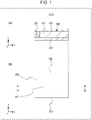
- Fig. 1 illustrates a schematic structure of a battery 1000 according to the first embodiment.
- Fig. 1(a) is an x-z diagram (1A cross-sectional view) illustrating the schematic structure of the battery 1000 according to the first embodiment.
- Fig. 1(b) is an x-y diagram (top perspective view) illustrating the schematic structure of the battery 1000 according to the first embodiment.
- the battery 1000 of the first embodiment includes an electrode layer 100, a counter electrode layer 200, and a solid electrolyte layer 300.
- the counter electrode layer 200 is a layer that serves as the counter electrode for the electrode layer 100.
- the solid electrolyte layer 300 is positioned between the electrode layer 100 and the counter electrode layer 200.
- the solid electrolyte layer 300 has a first region 310 and a second region 320.
- the first region 310 is a region that contains a first solid electrolyte material.
- the first region 310 is positioned within the region where the electrode layer 100 and the counter electrode layer 200 face each other.
- the second region 320 is a region that contains a second solid electrolyte material.
- the second region 320 is positioned on the outer peripheral side of the region where the electrode layer 100 and the counter electrode layer 200 face each other.
- the second region 320 is in contact with the first region 310.
- the second density is higher than the first density.
- the first density is the density of the first solid electrolyte material in the first region 310.
- the second density is the density of the second solid electrolyte material in the second region 320.
- the density of the solid electrolyte material in the outer rim portion of the solid electrolyte layer 300 can be increased.
- the thermal conductivity of the outer rim portion (in other words, the second region 320) of the solid electrolyte layer 300 can be adjusted to be higher than the thermal conductivity of the center portion (in other words, the first region 310) of the solid electrolyte layer 300.
- the heat from the center portion of the solid electrolyte layer 300 which is the portion likely to bear a high temperature during operation of the battery, is easily transferred (dissipated) to the outer rim portion of the solid electrolyte layer 300.
- first region 310 and the second region 320 are both regions that contain solid electrolyte materials (in other words, metal ion-conducting materials), matching and adhesion at the interface where the first region 310 and the second region 320 contact each other can be improved. That is to say, through the bonded interface between the first region 310 and the second region 320, metal ions are conducted by the solid electrolyte materials and, at the same time, the exothermic components are passed on so as to enable heat transfer from the first region 310 to the second region 320.
- solid electrolyte materials in other words, metal ion-conducting materials
- the heat generated in the center portion of the battery (for example, heat generated in the first region 310, the electrode layer 100, or the counter electrode layer 200) can be more easily dissipated to the surface of the solid electrolyte layer 300 (and the outside of the battery) through the outer rim portion (in other words, the second region 320) of the solid electrolyte layer 300 where the solid electrolyte material density is high (in other words, the thermal conductivity is high).
- the non-uniformity in temperature (temperature variation) in the solid electrolyte layer 300 containing the solid electrolyte material for example, an inorganic solid electrolyte
- the homogeneousness of the temperature inside the battery can be maintained.
- variation in properties inside the battery depending on the position caused by the temperature variation can be suppressed.
- deterioration of the battery performance can be suppressed.
- the service life of the battery can be extended.
- the solid electrolyte layer 300 positioned between the electrode layer 100 and the counter electrode layer 200 has the heat-dissipating function described above, heat generated from both the electrode layer 100 and the counter electrode layer 200 can be transferred to the outer rim portion of the battery through one battery component, which is the solid electrolyte layer 300. Furthermore, since the solid electrolyte layer 300 is positioned in the center portion (that is, the portion between the electrode layer 100 and the counter electrode layer 200) inside the battery, heat generated in the center portion of the battery can be more easily transferred to the outer rim portion of the battery compared to the structure in which a heat-dissipating member is installed on the electrode layer 100 (or counter electrode layer 200) side only.
- the strength of the second region 320 can be increased by increasing the solid electrolyte material density in the second region 320. In this manner, at least part of the outer rim of the first region 310 can be covered with the second region 320 having a higher strength. Thus, breaking of the first region 310 having a relatively low strength (for example, collapse of the first solid electrolyte material) can be suppressed by the second region 320. Thus, the strength of the battery can be improved.
- the second region 320 having a higher solid electrolyte material density can be interposed between the first region 310 and the outside of the battery (for example, outside air).
- the outside air for example, atmospheric air, humid air, or the like
- the environmental resistance of the battery can be improved.
- the electrode layer 100 may contain an electrode active material.
- the counter electrode layer 200 may contain a counter electrode active material.
- the density of the electrode active material in the first region 310 (for example, when the electrode active material is granular, the packing density of the particles of the electrode active material) and the density of the counter electrode active material (for example, when the counter electrode active material is granular, the packing density of the particles of the counter electrode active material) are both lower than the first density.
- the density of the electrode active material and the density of the counter electrode active material in the second region 320 are both lower than the second density.
- the first region 310 and the second region 320 can be placed in a portion where the densities of the electrode active material and the counter electrode active material are low (in other words, the portion that is remote from both the electrode layer 100 and the counter electrode layer 200 and that lies in a portion closer to the center in the solid electrolyte layer 300). That is, the first region 310 and the second region 320 having high heat dissipating properties can be placed in a portion closer to the center inside the battery.
- heat generated in the center portion of the battery can be more easily transferred to the outer rim portion of the battery compared to the structure in which a heat-dissipating member is installed only in a portion closer to the electrode layer 100 (a portion closer to the counter electrode layer 200).
- the first region 310 and the second region 320 may each be a region not containing an electrode active material or a counter electrode active material.
- the first region 310 and the second region 320 can be placed in a portion where the electrode active material and the counter electrode active material are not contained (in other words, the portion that is remote from both the electrode layer 100 and the counter electrode layer 200 and that lies in a portion closer to the center in the solid electrolyte layer 300). That is, the first region 310 and the second region 320 having high heat dissipating properties can be placed in a portion closer to the center inside the battery. As a result, heat generated in the center portion of the battery can be more easily transferred to the outer rim portion of the battery compared to the structure in which a heat-dissipating member is installed only in a portion closer to the electrode layer 100 (a portion closer to the counter electrode layer 200).
- the range in which the electrode layer 100 is formed may have the same size as or a different size from the range in which the counter electrode layer 200 is formed.
- the electrode layer 100 and the counter electrode layer 200 may have the same shape or different shapes.
- the electrode layer 100 may be a positive electrode layer.
- the electrode active material is a positive electrode active material.
- the counter electrode layer 200 is a negative electrode layer.
- the counter electrode active material is a negative electrode active material.
- the electrode layer 100 may be a negative electrode layer.
- the electrode active material is a negative electrode active material.
- the counter electrode layer 200 is a positive electrode layer.
- the counter electrode active material is a positive electrode active material.
- the positive electrode layer may be a layer mainly composed of a positive electrode material (for example, a positive electrode active material).
- a positive electrode active material for example, a positive electrode active material
- Examples of the positive electrode active material contained in the positive electrode layer include various materials that can intercalate and deintercalate metal ions (for example, Li ions and Mg ions).
- Known positive electrode active materials can be used as the material for the positive electrode active material.
- the positive electrode active material examples include layer oxides such as lithium-nickel complex oxides (LiNi x M 1-x O 2 (where M represents at least one element selected from Co, Al, Mn, V, Cr, Mg, Ca, Ti, Zr, Nb, Mo, and W, and x is any desired natural number)), lithium cobaltate (LiCoO 2 ), lithium nickelate (LiNiO 2 ), and lithium manganate (LiMn 2 O 4 ); and transition metal oxides that contain lithium ions, such as lithium iron phosphate having an olivine structure (LiFePO 4 ) and lithium manganate having a spinel structure (LiMn 2 O 4 , Li 2 MnO 3 , and LiMO 2 ).
- layer oxides such as lithium-nickel complex oxides (LiNi x M 1-x O 2 (where M represents at least one element selected from Co, Al, Mn, V, Cr, Mg, Ca, Ti, Zr, Nb, Mo, and W, and
- sulfur (S) and sulfides such as lithium sulfide (Li 2 S) can be used.
- Positive electrode active material particles coated with (or doped with) lithium niobate (LiNbO 3 ) or the like can also be used as the positive electrode active material.
- the positive electrode layer may be a mixture layer composed of a positive electrode active material and other additive materials.
- additive materials for the positive electrode layer include solid electrolytes (for example, an inorganic solid electrolyte), conductive aids (for example, acetylene black), and bonding binders (for example, polyethylene oxide and polyvinylidene fluoride). Mixing a particular percentage of a solid electrolyte to a positive electrode layer can improve the ion conductivity of the positive electrode layer.
- the thickness of the positive electrode layer may be, for example, 5 to 300 ⁇ m.
- the negative electrode layer may be a layer mainly composed of a negative electrode material (for example, a negative electrode active material).
- a negative electrode active material for example, a negative electrode active material
- the negative electrode active material contained in the negative electrode layer include various materials that can intercalate and deintercalate metal ions (for example, Li ions and Mg ions).
- Known negative electrode active materials can be used as the material for the negative electrode active material.
- the negative electrode active material that can be used include carbon materials (for example, natural graphite, artificial graphite, graphite carbon fibers, and resin baked carbon), and alloy-based material that can be combined with solid electrolytes.
- alloy-based materials examples include lithium alloys (LiAl, LiZn, Li 3 Bi, Li 3 Cd, Li 3 Sb, Li 4 Si, Li 4.4 Pb, Li 4.4 Sn, Li 0.17 C, and LiC 6 ), lithium titanate (Li 4 Ti 5 O 12 ), and oxides of metals (Zn etc.).
- the negative electrode layer may be a mixture layer composed of a negative electrode active material and other additive materials.
- additive materials for the negative electrode layer include solid electrolytes (for example, an inorganic solid electrolyte), conductive aids (for example, acetylene black), and bonding binders (for example, polyethylene oxide and polyvinylidene fluoride). Mixing a particular percentage of a solid electrolyte to a negative electrode layer can improve the ion conductivity of the negative electrode layer.
- the thickness of the negative electrode layer is, for example, 5 to 300 ⁇ m.
- Commonly known solid electrolytes for batteries can be used as the first solid electrolyte material and the second solid electrolyte material.
- Commonly known solid electrolytes for example, inorganic solid electrolytes
- examples of the inorganic solid electrolytes that can be used include sulfide solid electrolytes and oxide solid electrolytes.
- solid electrolytes examples include lithium-containing sulfides (for example, those based on Li 2 S-P 2 S5, Li 2 S-SiS 2 , Li 2 S-B 2 S 3 , Li 2 S-GeS 2 , Li 2 S-SiS 2 -LiI, Li 2 S-SiS 2 -Li 3 PO 4 , Li 2 S-Ge 2 S 2 , Li 2 S-GeS 2 -P 2 S 5 , and Li 2 S-GeS 2 -ZnS).
- lithium-containing sulfides for example, those based on Li 2 S-P 2 S5, Li 2 S-SiS 2 , Li 2 S-B 2 S 3 , Li 2 S-GeS 2 , Li 2 S-SiS 2 -LiI, Li 2 S-SiS 2 -Li 3 PO 4 , Li 2 S-Ge 2 S 2 , Li 2 S-GeS 2 -P 2 S 5 , and Li 2 S-GeS
- solid electrolytes examples include lithium-containing metal oxides (for example, Li 2 -SiO 2 and Li 2 -SiO 2 -P 2 O 5 ), lithium-containing metal nitrides (for example Li x P y O 1-z N 2 (where x, y, and z each represent any desired natural number)), lithium phosphate (Li 3 PO 4 ), and lithium-containing transition metal oxides (for example, lithium titanium oxide). These materials may be used alone or in combination as the solid electrolyte.
- lithium-containing metal oxides for example, Li 2 -SiO 2 and Li 2 -SiO 2 -P 2 O 5
- lithium-containing metal nitrides for example Li x P y O 1-z N 2 (where x, y, and z each represent any desired natural number
- lithium phosphate Li 3 PO 4
- lithium-containing transition metal oxides for example, lithium titanium oxide
- the solid electrolyte layer 300 (for example, at least one (for example, all) of the first region 310, the second region 320, and a third region 330) can contain, in addition to the solid electrolyte material, a bonding binder (for example, polyethylene oxide or polyethylene oxide).
- a bonding binder for example, polyethylene oxide or polyethylene oxide.
- the thickness of the solid electrolyte layer 300 may be, for example, 5 to 150 ⁇ m.
- the first solid electrolyte material and the second solid electrolyte material may be materials different from each other. In this manner, for example, while a solid electrolyte material having a high heat dissipating property is used as the second solid electrolyte material, a solid electrolyte material having high metal ion conductivity can be used as the first solid electrolyte material.
- first solid electrolyte material and the second solid electrolyte material may the same material.
- the same solid electrolyte material can be contained in the first region 310 and the second region 320.
- the physical property values for example, a thermal expansion coefficient
- the matching and adhesion at the interface where the first region 310 and the second region 320 contact each other can be further improved. In other words, occurrence of structural defects that inhibit heat transfer between the first region 310 and the second region 320 can be further suppressed.
- the heat generated in the center portion of the battery (for example, heat generated in the first region 310, the electrode layer 100, or the counter electrode layer 200) can be more easily dissipated to the surface of the solid electrolyte layer 300 (and the outside of the battery) through the second region 320.
- the battery production process for example, mixing of the mixture and application of the mixture, etc.
- the first solid electrolyte material may be constituted by particles.
- the first region 310 is a region that contains particles of the first solid electrolyte material.
- the first density is the density of the particles of the first solid electrolyte material in the first region 310 (in other words, the packing density).
- the second solid electrolyte material may be constituted by particles.
- the second region 320 is a region that contains particles of the second solid electrolyte material.
- the second density is the density of the particles of the second solid electrolyte material in the second region 320 (in other words, the packing density).
- the first region 310 may be a region in contact with at least one of the electrode layer 100 and the counter electrode layer 200.
- the first region 310 may be a region in contact with both of the electrode layer 100 and the counter electrode layer 200.
- the second region 320 may be positioned only within the region where the electrode layer 100 and the counter electrode layer 200 face each other.
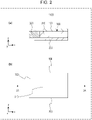
- Fig. 2 illustrates a schematic structure of a battery 1100 according to the first embodiment.
- Fig. 2(a) is an x-z diagram (2A cross-sectional view) illustrating the schematic structure of the battery 1100 according to the first embodiment.
- Fig. 2(b) is an x-y diagram (top perspective view) illustrating the schematic structure of the battery 1100 according to the first embodiment.
- the second region 320 may be positioned within the region where the electrode layer 100 and the counter electrode layer 200 face each other and also outside the region where the electrode layer 100 and the counter electrode layer 200 face each other. In this manner, the second region 320 can be placed to be more remote from the center portion of the battery. Thus, the heat dissipating property by the second region 320 can be further enhanced.
- the second region 320 may be a region in contact with at least one of the electrode layer 100 and the counter electrode layer 200.
- the second region 320 may be a region in contact with both of the electrode layer 100 and the counter electrode layer 200.
- Fig. 3 illustrates a schematic structure of a battery 1200 according to the first embodiment.
- Fig. 3(a) is an x-z diagram (3A cross-sectional view) illustrating the schematic structure of the battery 1200 according to the first embodiment.
- Fig. 3(b) is an x-y diagram (top perspective view) illustrating the schematic structure of the battery 1200 according to the first embodiment.
- the second region 320 may be positioned only outside the region where the electrode layer 100 and the counter electrode layer 200 face each other. In this manner, the second region 320 can be placed to be more remote from the center portion of the battery. Thus, the heat dissipating property by the second region 320 can be further enhanced. Furthermore, the area of the first region 310 positioned within the region where the electrode layer 100 and the counter electrode layer 200 face each other can be further increased. In other words, the area of the first region 310, which has a function of transferring metal ions, between the electrode layer 100 and the counter electrode layer 200 can be further increased.
- the second region 320 is positioned on the outer peripheral side of the region where the electrode layer 100 and the counter electrode layer 200 face each other. encompasses the structures (in other words, the arrangement of the second region 320) illustrated in Figs. 1 to 3 .
- the region where the electrode layer 100 and the counter electrode layer 200 face each other encompasses, for example, “when viewed in a stacking direction of the electrode layer 100 and the counter electrode layer 200 (in other words, in the z direction in the drawing), a region where a part of a main surface (or the entire main surface) of the electrode layer 100 overlaps a part of a main surface (or the entire main surface) of the counter electrode layer 200 (in other words, the overlapping region)".
- the structure in which the electrode layer 100 and the counter electrode layer 200 face each other encompasses, for example, “a structure in which another member (for example, the solid electrolyte layer 300) is disposed between the main surface of the electrode layer 100 and the main surface of the counter electrode layer 200 that face each other.
- the second region 320 may be positioned only at one end portion of the solid electrolyte layer 300.
- the solid electrolyte layer 300 has a rectangular shape (for example, a quadrilateral shape) as illustrated in Figs. 1 to 3
- the second region 320 may be disposed at only one side of this shape.
- the second region 320 may be positioned at two or more end portions among the end portions of the solid electrolyte layer 300.
- the solid electrolyte layer 300 has a rectangular shape (for example, a quadrilateral shape) as illustrated in Figs. 1 to 3
- the second region 320 may be disposed at two or more sides of this shape. In this manner, the heat dissipating property (and strength, environmental resistance, etc.) can be enhanced at the two or more end portions.
- Fig. 4 illustrates a schematic structure of a battery 2000 according to the second embodiment.
- Fig. 4(a) is an x-z diagram (4A cross-sectional view) illustrating the schematic structure of the battery 2000 according to the second embodiment.
- Fig. 4(b) is an x-y diagram (top perspective view) illustrating the schematic structure of the battery 2000 according to the second embodiment.
- the battery 2000 according to the second embodiment further includes the following features in addition to the features of the battery 1000 of the first embodiment described above.
- the second region 320 surrounds the first region 310.
- the density of the solid electrolyte material in the outer rim portion (for example, the entire outer rim portion) on the four sides of the solid electrolyte layer 300 can be increased.
- the heat from the center portion of the solid electrolyte layer 300 is easily transferred (dissipated) to the outer rim portion of the solid electrolyte layer 300 close to the parts where heat has been generated.
- the heat generated in the center portion of the battery for example, heat generated in the first region 310, the electrode layer 100, or the counter electrode layer 200
- the heat generated in the center portion of the battery can be more easily dissipated to the surface of the solid electrolyte layer 300 (and the outside of the battery).
- the outer rim on the four sides (for example, the entire outer rim) of the first region 310 can be covered with the second region 320 having a higher strength.
- breaking of the outer rim on the four sides of the first region 310 having a relatively low strength for example, collapse of the first solid electrolyte material
- the strength of the battery can be further improved.
- the second region 320 having a higher solid electrolyte material density can be interposed between the outer rim on the four sides of the first region 310 and the outside of the battery (for example, outside air).
- the outside air for example, atmospheric air, humid air, or the like
- the environmental resistance of the battery can be further improved.
- the second region 320 may be positioned only within the region where the electrode layer 100 and the counter electrode layer 200 face each other.
- Fig. 5 illustrates a schematic structure of a battery 2100 according to the second embodiment.
- Fig. 5(a) is an x-z diagram (5A cross-sectional view) illustrating the schematic structure of the battery 2100 according to the second embodiment.
- Fig. 5(b) is an x-y diagram (top perspective view) illustrating the schematic structure of the battery 2100 according to the second embodiment.
- the second region 320 may be positioned within the region where the electrode layer 100 and the counter electrode layer 200 face each other and also outside the region where the electrode layer 100 and the counter electrode layer 200 face each other. In this manner, the second region 320 can be placed on the four sides of the battery and to be more remote from the center portion of the battery. Thus, the heat dissipating property by the second region 320 can be further enhanced.
- the second region 320 may be a region in contact with at least one of the electrode layer 100 and the counter electrode layer 200.
- the second region 320 may be a region in contact with both of the electrode layer 100 and the counter electrode layer 200.
- Fig. 6 illustrates a schematic structure of a battery 2200 according to the second embodiment.
- Fig. 6(a) is an x-z diagram (6A cross-sectional view) illustrating the schematic structure of the battery 2200 according to the second embodiment.
- Fig. 6(b) is an x-y diagram (top perspective view) illustrating the schematic structure of the battery 2200 according to the second embodiment.
- the second region 320 may be positioned only outside the region where the electrode layer 100 and the counter electrode layer 200 face each other. In this manner, the second region 320 can be placed to be more remote from the center portion of the battery. Thus, the heat dissipating property by the second region 320 can be further enhanced. Furthermore, the area of the first region 310 positioned within the region where the electrode layer 100 and the counter electrode layer 200 face each other can be further increased. In other words, the area of the first region 310, which has a function of transferring metal ions, between the electrode layer 100 and the counter electrode layer 200 can be further increased.
- the second region 320 surrounds the first region 310 also encompasses the structures (in other words, the arrangement of the second region 320) illustrated in Figs. 4 to 6 .
- the second region 320 surrounds the first region 310 encompasses, for example, "the second region 320 contacts all of the end portions of the first region 310".
- the first region 310 has a rectangular shape (for example, a quadrilateral shape) as illustrated in Figs. 4 to 6
- the second region 320 may be in contact with all of the sides of this shape.
- the outer peripheral side surface of the first region 310 may be bonded to the inner peripheral side surface of the second region 320.
- Fig. 7 illustrates a schematic structure of a battery 3000 according to the third embodiment.
- Fig. 7(a) is an x-z diagram (7A cross-sectional view) illustrating the schematic structure of the battery 3000 according to the third embodiment.
- Fig. 7(b) is an x-y diagram (top perspective view) illustrating the schematic structure of the battery 3000 according to the third embodiment.
- the battery 3000 according to the third embodiment further includes the following features in addition to the features of the battery 1000 of the first embodiment described above.
- the second region 320 is in contact with an end portion (for example, a side surface) of the electrode layer 100.
- the second region 320 which has a high solid electrolyte material density, can be disposed to be in contact with the outer rim portion (for example, at least one end portion) of the electrode layer 100.
- the heat from the electrode layer 100 is easily transferred (dissipated) to the second region 320.
- the heat generated in the center portion of the battery in other words, heat generated in the electrode layer 100
- the outer rim portion (for example, at least one end portion) of the electrode layer 100 can be covered with the second region 320 having a higher strength.
- breaking of the outer rim portion of the electrode layer 100 which has a relatively low strength (for example, collapse of the electrode material), can be suppressed by the second region 320.
- the strength of the battery can be further improved.
- the second region 320 having a higher solid electrolyte material density can be interposed between the outer rim portion of the electrode layer 100 and the outside of the battery (for example, outside air).
- the outside air for example, atmospheric air, humid air, or the like
- the environmental resistance of the battery can be further improved.
- the second region 320 may be in contact with only one end portion of the electrode layer 100.
- the electrode layer 100 has a rectangular shape (for example, a quadrilateral shape) as illustrated in Fig. 7
- the second region 320 may be disposed to be in contact with only one side of this shape.
- the second region 320 may be in contact with two or more end portions among the end portions of the electrode layer 100.
- the electrode layer 100 has a rectangular shape (for example, a quadrilateral shape) as illustrated in Fig. 7
- the second region 320 may be disposed to be in contact with two or more sides of this shape. In this manner, the heat dissipating property (and strength, environmental resistance, etc.) can be enhanced at the two or more end portions.
- Fig. 8 illustrates a schematic structure of a battery 3100 according to the third embodiment.
- Fig. 8(a) is an x-z diagram (8A cross-sectional view) illustrating the schematic structure of the battery 3100 according to the third embodiment.
- Fig. 8(b) is an x-y diagram (top perspective view) illustrating the schematic structure of the battery 3100 according to the third embodiment.
- the second region 320 may surround the electrode layer 100.
- the second region 320 which has a high solid electrolyte material density, can be disposed to be in contact with the outer rim portion on the four sides (for example, the entire outer rim portion) of the electrode layer 100.
- the heat from the electrode layer 100 is easily transferred (dissipated) to the second region 320 close to the parts where heat has been generated.
- the heat generated in the center portion of the battery in other words, heat generated in the electrode layer 100
- the outer rim portion on the four sides (for example, the entire outer rim) of the electrode layer 100 can be covered with the second region 320 having a higher strength.
- breaking of the outer rim portion on the four sides of the electrode layer 100 which has a relatively low strength (for example, collapse of the electrode material), can be further suppressed by the second region 320.
- the strength of the battery can be further improved.
- the second region 320 having a higher solid electrolyte material density can be interposed between the outer rim portion on the four sides of the electrode layer 100 and the outside of the battery (for example, outside air).
- the outside air for example, atmospheric air, humid air, or the like
- the environmental resistance of the battery can be further improved.
- Fig. 9 illustrates a schematic structure of a battery 3200 according to the third embodiment.
- Fig. 9(a) is an x-z diagram (9A cross-sectional view) illustrating the schematic structure of the battery 3200 according to the third embodiment.
- Fig. 9(b) is an x-y diagram (top perspective view) illustrating the schematic structure of the battery 3200 according to the third embodiment.
- the battery 3200 according to the third embodiment further includes the following features in addition to the features of the battery 3000 of the third embodiment described above.
- the second region 320 is in contact with an end portion (for example, a side surface) of the counter electrode layer 200.
- the second region 320 which has a high solid electrolyte material density, can be disposed to be in contact with the outer rim portion (for example, at least one end portion) of the counter electrode layer 200.
- the heat from the counter electrode layer 200 is easily transferred (dissipated) to the second region 320.
- the heat generated in the center portion of the battery in other words, heat generated in the counter electrode layer 200
- the outer rim portion (for example, at least one end portion) of the counter electrode layer 200 can be covered with the second region 320 having a higher strength.
- breaking of the outer rim portion of the counter electrode layer 200 which has a relatively low strength (for example, collapse of the electrode material), can be suppressed by the second region 320.
- the strength of the battery can be further improved.
- the second region 320 having a higher solid electrolyte material density can be interposed between the outer rim portion of the counter electrode layer 200 and the outside of the battery (for example, outside air).
- the outside air for example, atmospheric air, humid air, or the like
- the environmental resistance of the battery can be further improved.
- the second region 320 may be in contact with only one end portion of the counter electrode layer 200.
- the second region 320 may be disposed to be in contact with only one side of this shape.
- the second region 320 may be in contact with two or more end portions among the end portions of the counter electrode layer 200.
- the second region 320 may be disposed to be in contact with two or more sides of this shape. In this manner, the heat dissipating property (and strength, environmental resistance, etc.) can be enhanced at the two or more end portions.
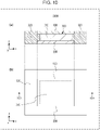
- Fig. 10 illustrates a schematic structure of a battery 3300 according to the third embodiment.
- Fig. 10(a) is an x-z diagram (10A cross-sectional view) illustrating the schematic structure of the battery 3300 according to the third embodiment.
- Fig. 10(b) is an x-y diagram (top perspective view) illustrating the schematic structure of the battery 3300 according to the third embodiment.
- the second region 320 may surround the counter electrode layer 200.
- the second region 320 which has a high solid electrolyte material density, can be disposed to be in contact with the outer rim portion on the four sides (for example, the entire outer rim portion) of the counter electrode layer 200.
- the heat from the counter electrode layer 200 is easily transferred (dissipated) to the second region 320 close to the parts where heat has been generated.
- the heat generated in the center portion of the battery in other words, heat generated in the counter electrode layer 200
- the outer rim portion on the four sides (for example, the entire outer rim) of the counter electrode layer 200 can be covered with the second region 320 having a higher strength.
- breaking of the outer rim portion on the four sides of the counter electrode layer 200, which has a relatively low strength (for example, collapse of the electrode material) can be further suppressed by the second region 320.
- the strength of the battery can be further improved.
- the second region 320 having a higher solid electrolyte material density can be interposed between the outer rim portion on the four sides of the counter electrode layer 200 and the outside of the battery (for example, outside air).
- the outside air for example, atmospheric air, humid air, or the like
- the environmental resistance of the battery can be further improved.
- the second region 320 surrounds the electrode layer 100 (or the counter electrode layer 200) encompasses, for example, “the second region 320 contacts all of the end portions of the electrode layer 100 (or the counter electrode layer 200)".
- the second region 320 may be in contact with all of the sides of this shape.
- the second region 320 may be also positioned within the region where the electrode layer 100 and the counter electrode layer 200 face each other. Alternatively, the second region 320 may be positioned only outside the region where the electrode layer 100 and the counter electrode layer 200 face each other.
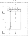
- Fig. 11 illustrates a schematic structure of a battery 3400 according to the third embodiment.
- Fig. 11(a) is an x-z diagram (11A cross-sectional view) illustrating the schematic structure of the battery 3400 according to the third embodiment.
- Fig. 11(b) is an x-y diagram (top perspective view) illustrating the schematic structure of the battery 3400 according to the third embodiment.
- the first region 310 may have a first projecting portion 311.
- the first projecting portion 311 is a portion that projects outward from the region where the electrode layer 100 and the counter electrode layer 200 face each other.
- the second region 320 may cover the first projecting portion 311.
- the contact area between the first region 310 and the second region 320 can be further increased.
- the heat from the center portion of the solid electrolyte layer 300 is easily transferred (dissipated) to the outer rim portion of the solid electrolyte layer 300.
- the heat generated in the center portion of the battery for example, heat generated in the first region 310, the electrode layer 100, or the counter electrode layer 200
- the heat generated in the center portion of the battery can be more easily dissipated to the surface of the solid electrolyte layer 300 (and the outside of the battery).
- the second region 320 may be in contact with an end portion (for example, a side surface) of the electrode layer 100 and an end portion (for example, a side surface) of the counter electrode layer 200.
- Fig. 12 illustrates a schematic structure of a battery 3500 according to the third embodiment.
- Fig. 12(a) is an x-z diagram (12A cross-sectional view) illustrating the schematic structure of the battery 3500 according to the third embodiment.
- Fig. 12(b) is an x-y diagram (top perspective view) illustrating the schematic structure of the battery 3500 according to the third embodiment.
- the first projecting portion 311 may surround the region where the electrode layer 100 and the counter electrode layer 200 face each other.
- the second region 320 may cover the first projecting portion 311 exposing from around the region where the electrode layer 100 and the counter electrode layer 200 face each other.
- the contact area between the first region 310 and the second region 320 can be further increased.
- the heat from the center portion of the solid electrolyte layer 300 is easily transferred (dissipated) to the outer rim portion of the solid electrolyte layer 300 close to the parts where heat has been generated.
- the heat generated in the center portion of the battery for example, heat generated in the first region 310, the electrode layer 100, or the counter electrode layer 200
- the heat generated in the center portion of the battery can be more easily dissipated to the surface of the solid electrolyte layer 300 (and the outside of the battery).
- the second region 320 may surround the electrode layer 100 and the counter electrode layer 200.
- Fig. 13 illustrates a schematic structure of a battery 4000 according to the fourth embodiment.
- Fig. 13(a) is an x-z diagram (13A cross-sectional view) illustrating the schematic structure of the battery 4000 according to the fourth embodiment.
- Fig. 13(b) is an x-y diagram (top perspective view) illustrating the schematic structure of the battery 4000 according to the fourth embodiment.
- the battery 4000 according to the fourth embodiment further includes the following features in addition to the features of the battery 1000 of the first embodiment described above.
- the battery 4000 of the fourth embodiment further includes an electrode current collector 400 and a counter electrode current collector 500.
- the electrode current collector 400 is a current collector electrically coupled to the electrode layer 100.
- the counter electrode current collector 500 is a current collector electrically coupled to the counter electrode layer 200.
- the second region 320 is positioned between the electrode current collector 400 and the counter electrode current collector 500 and is in contact with the electrode current collector 400 and the counter electrode current collector 500.
- the second region 320 which has a high solid electrolyte material density (in other words, a high strength), can function as a high-strength skeleton structure in the outer rim portion of the solid electrolyte layer 300 (in other words, the outer rim portion of the electrode current collector 400 and the counter electrode current collector 500).
- the second region 320 suppresses deformation or structural defects in the outer rim portion of the electrode current collector 400 and the counter electrode current collector 500.
- the battery has a large area and a reduced layer thickness (for example, a battery designed as a high-output, highcapacity battery) or when the battery is an all-solid battery not equipped with separators, short-circuiting caused by contact between the electrode current collector 400 and the counter electrode current collector 500 can be suppressed by the second region 320.
- the deformation resistance and impact resistance of the battery can be further enhanced.
- the electrode current collector 400 may be electrically coupled to the electrode layer 100 by making direct contact with the electrode layer 100.
- a separate conductive member may be interposed between the electrode current collector 400 and the electrode layer 100.
- the electrode current collector 400 may be larger in size than the electrode layer 100.
- the area of the main surface of the electrode current collector 400 may be larger than the area of the main surface of the electrode layer 100.
- the electrode layer 100 may be formed in a range narrower than the electrode current collector 400.
- the counter electrode current collector 500 may be electrically coupled to the counter electrode layer 200 by making direct contact with the counter electrode layer 200.
- a separate conductive member may be interposed between the counter electrode current collector 500 and the counter electrode layer 200.
- the counter electrode current collector 500 may be larger in size than the counter electrode layer 200.
- the area of the main surface of the counter electrode current collector 500 may be larger than the area of the main surface of the counter electrode layer 200.
- the counter electrode layer 200 may be formed in a range narrower than the counter electrode current collector 500.
- the second region 320 may be positioned within the region where the electrode current collector 400 and the counter electrode current collector 500 face each other without the electrode layer 100 and the counter electrode layer 200 therebetween among the region where the electrode current collector 400 and the counter electrode current collector 500 face each other.
- the region where the electrode current collector 400 and the counter electrode current collector 500 face each other encompasses, for example, “when viewed in a stacking direction of the electrode current collector 400 and the counter electrode current collector 500 (in other words, in the z direction in the drawing), a region where a part of a main surface (or the entire main surface) of the electrode current collector 400 overlaps a part of a main surface (or the entire main surface) of the counter electrode current collector 500 (in other words, the overlapping region)".
- the structure in which the electrode current collector 400 and the counter electrode current collector 500 face each other encompasses, for example, “a structure in which another member (for example, the electrode layer 100, the counter electrode layer 200, the solid electrolyte layer 300, etc.) is disposed between the main surface of the electrode current collector 400 and the main surface of the counter electrode current collector 500 that face each other.
- another member for example, the electrode layer 100, the counter electrode layer 200, the solid electrolyte layer 300, etc.
- the electrode layer 100 may be a positive electrode layer.
- the electrode active material is a positive electrode active material.
- the electrode current collector 400 is a positive electrode current collector.
- the counter electrode layer 200 is a negative electrode layer.
- the counter electrode active material is a negative electrode active material.
- the counter electrode current collector 500 is a negative electrode current collector.
- the electrode layer 100 may be a negative electrode layer.
- the electrode active material is a negative electrode active material.
- the electrode current collector 400 is a negative electrode current collector.
- the counter electrode layer 200 is a positive electrode layer.
- the counter electrode active material is a positive electrode active material.
- the counter electrode current collector 500 is a positive electrode current collector.
- Examples of the positive electrode current collector that can be used include metal films (for example, metal foils) composed of metal materials (for example, aluminum, copper, and stainless steel). Examples of the positive electrode current collector that can be used also include metal films formed of alloys containing these metal materials. Another example of the positive electrode current collector that can be used is a member prepared by forming (or bonding) a film of the metal material on a film composed of a different material.
- the thickness of the positive electrode current collector may be, for example, 5 to 100 ⁇ m.
- Examples of the negative electrode current collector that can be used include metal films (for example, metal foils) composed of metal materials (for example, nickel, copper, and stainless steel). Examples of the negative electrode current collector that can be used also include metal films formed of alloys containing these metal materials. Another example of the negative electrode current collector that can be used is a member prepared by forming (or bonding) a film of the metal material on a film composed of a different material.
- the thickness of the negative electrode current collector may be, for example, 5 to 100 ⁇ m.
- the second region 320 may be positioned at only one end portion of the electrode current collector 400 (and the counter electrode current collector 500).
- the electrode current collector 400 (and the counter electrode current collector 500) has a rectangular shape (for example, a quadrilateral shape) as illustrated in Fig. 13
- the second region 320 may be disposed at only one side of this shape.
- the second region 320 may be positioned at two or more end portions among the end portions of the electrode current collector 400 (and the counter electrode current collector 500).
- the electrode current collector 400 (and the counter electrode current collector 500) has a rectangular shape (for example, a quadrilateral shape) as illustrated in Fig. 13
- the second region 320 may be disposed at two or more sides of this shape. In this manner, short-circuiting caused by contact between the electrode current collector 400 and the counter electrode current collector 500 can be suppressed at two or more end portions.
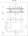
- Fig. 14 illustrates a schematic structure of a battery 4100 according to the fourth embodiment.
- Fig. 14(a) is an x-z diagram (14A cross-sectional view) illustrating the schematic structure of the battery 4100 according to the fourth embodiment.
- Fig. 14(b) is an x-y diagram (top perspective view) illustrating the schematic structure of the battery 4100 according to the fourth embodiment.
- the second region 320 may surround the first region 310, the electrode layer 100, and the counter electrode layer 200.
- the second region 320 surrounding the first region 310, the electrode layer 100, and the counter electrode layer 200 may be in contact with the electrode current collector 400 and the counter electrode current collector 500.
- short-circuiting caused by contact between the electrode current collector 400 and the counter electrode current collector 500 can be further suppressed around (for example, on the four sides of) the multilayer body constituted by the first region 310, the electrode layer 100, and the counter electrode layer 200.
- Fig. 15 illustrates a schematic structure of a battery 4200 according to the fourth embodiment.
- Fig. 15(a) is an x-z diagram (15A cross-sectional view) illustrating the schematic structure of the battery 4200 according to the fourth embodiment.
- Fig. 15(b) is an x-y diagram (top perspective view) illustrating the schematic structure of the battery 4200 according to the fourth embodiment.
- the first region 310 may be positioned in the region where the electrode layer 100 and the counter electrode layer 200 face each other.
- the second region 320 may be positioned within the entire region where the electrode current collector 400 and the counter electrode current collector 500 face each other without the electrode layer 100 and the counter electrode layer 200 therebetween among the region where the electrode current collector 400 and the counter electrode current collector 500 face each other. In this manner, short-circuiting caused by contact between the electrode current collector 400 and the counter electrode current collector 500 can be further suppressed around (for example, on the four sides of) the multilayer body constituted by the first region 310, the electrode layer 100, and the counter electrode layer 200.
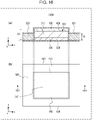
- Fig. 16 illustrates a schematic structure of a battery 4300 according to the fourth embodiment.
- Fig. 16(a) is an x-z diagram (16A cross-sectional view) illustrating the schematic structure of the battery 4300 according to the fourth embodiment.
- Fig. 16(b) is an x-y diagram (top perspective view) illustrating the schematic structure of the battery 4300 according to the fourth embodiment.
- the second distance D2 may be smaller than the first distance D1.
- the first distance D1 is the distance between the electrode current collector 400 and the counter electrode current collector 500 at a position in which the first region 310 lies.
- the second distance D2 is the distance between the electrode current collector 400 and the counter electrode current collector 500 at a position in which the second region 320 lies.
- a battery in which the outer rim portion of the solid electrolyte layer 300 (in other words, the outer rim portion of the electrode current collector 400 and the counter electrode current collector 500) is narrowed (in other words, a battery with narrowed outer peripheral side surfaces) can be configurated.
- the area of the exposed outer rim portion of the solid electrolyte layer 300 can be decreased.
- the outside air for example, atmospheric air, humid air, or the like
- the durability for example, the impact resistance
- the environmental resistance of the battery can be further improved.
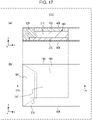
- Fig. 17 illustrates a schematic structure of a battery 5000 according to the fifth embodiment.
- Fig. 17(a) is an x-z diagram (17A cross-sectional view) illustrating the schematic structure of the battery 5000 according to the fifth embodiment.
- Fig. 17(b) is an x-y diagram (top perspective view) illustrating the schematic structure of the battery 5000 according to the fifth embodiment.
- the battery 5000 according to the fifth embodiment further includes the following features in addition to the features of the battery 1000 of the first embodiment described above.
- the range in which the counter electrode layer 200 is formed is larger than the range in which the electrode layer 100 is formed.
- the electrode layer 100 is positioned within the range in which the counter electrode layer 200 is formed.
- the counter electrode layer 200 is formed to have a larger area than the electrode layer 100, precipitation of metal (for example, lithium) in the counter electrode layer 200 can be suppressed. Thus, short-circuiting between the electrode layer 100 and the counter electrode layer 200 caused by metal precipitation can be prevented.
- metal for example, lithium
- the counter electrode layer 200 may be larger in size than the electrode layer 100.
- the area of the main surface of the counter electrode layer 200 may be larger than the area of the main surface of the electrode layer 100.
- the electrode layer 100 may be formed in a range narrower than the counter electrode layer 200.
- one end portion of the counter electrode layer 200 may be larger than the electrode layer 100.
- this end portion may be arranged not to face the electrode layer 100.
- Fig. 18 illustrates a schematic structure of a battery 5100 according to the fifth embodiment.
- Fig. 18(a) is an x-z diagram (18A cross-sectional view) illustrating the schematic structure of the battery 5100 according to the fifth embodiment.
- Fig. 18(b) is an x-y diagram (top perspective view) illustrating the schematic structure of the battery 5100 according to the fifth embodiment.
- the end portions (for example, all end portions) on the four sides of the counter electrode layer 200 may be arranged to not face the electrode layer 100. In this manner, precipitation of the metal (for example, lithium) in the counter electrode layer 200 can be further suppressed. Thus, short-circuiting between the electrode layer 100 and the counter electrode layer 200 caused by metal precipitation can be more reliably prevented.
- the second region 320 may lie in a region where the electrode layer 100 is absent among the region facing the counter electrode layer 200 (for example, the region in which the counter electrode layer 200 and the electrode current collector 400 face each other without the electrode layer 100 therebetween).
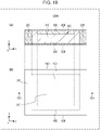
- Fig. 19 illustrates a schematic structure of a battery 5200 according to the fifth embodiment.
- Fig. 19(a) is an x-z diagram (19A cross-sectional view) illustrating the schematic structure of the battery 5200 according to the fifth embodiment.
- Fig. 19(b) is an x-y diagram (top perspective view) illustrating the schematic structure of the battery 5200 according to the fifth embodiment.
- the first region 310 may lie in a region where the electrode layer 100 is absent among the region facing the counter electrode layer 200 (for example, the region in which the counter electrode layer 200 and the electrode current collector 400 face each other without the electrode layer 100 therebetween).
- the area of the first region 310 positioned within the region where the electrode layer 100 and the counter electrode layer 200 face each other can be further increased.
- the area of the first region 310, which has a function of transferring metal ions, between the electrode layer 100 and the counter electrode layer 200 can be further increased. In this manner, precipitation of the metal (for example, lithium) in the counter electrode layer 200 can be further suppressed.
- Fig. 20 illustrates a schematic structure of a battery 5300 according to the fifth embodiment.
- Fig. 20(a) is an x-z diagram (20A cross-sectional view) illustrating the schematic structure of the battery 5300 according to the fifth embodiment.
- Fig. 20(b) is an x-y diagram (top perspective view) illustrating the schematic structure of the battery 5300 according to the fifth embodiment.
- the second region 320 may lie in a region where the electrode layer 100 is absent among the region facing the counter electrode layer 200 (for example, the region in which the counter electrode layer 200 and the electrode current collector 400 face each other without the electrode layer 100 therebetween).
- the second region 320 may be absent in the region where the electrode current collector 400 and the counter electrode current collector 500 face each other without the electrode layer 100 and the counter electrode layer 200 therebetween among the region where the electrode current collector 400 and the counter electrode current collector 500 face each other.
- Fig. 21 illustrates a schematic structure of a battery 6000 according to the sixth embodiment.
- Fig. 21 (a) is an x-z diagram (21A cross-sectional view) illustrating the schematic structure of the battery 6000 according to the sixth embodiment.
- Fig. 21 (b) is an x-y diagram (top perspective view) illustrating the schematic structure of the battery 6000 according to the sixth embodiment.
- the battery 6000 according to the sixth embodiment further includes the following features in addition to the features of the battery 1000 of the first embodiment described above.
- the solid electrolyte layer 300 has a third region 330.
- the third region 330 is a region that contains a third solid electrolyte material.
- the third region 330 is in contact with the second region 320.
- the second region 320 is positioned between the first region 310 and the third region 330.
- the third density is higher than the second density.
- the third density is the density of the third solid electrolyte material in the third region 330.
- the density of the solid electrolyte material can be gradually changed across the first region 310, the second region 320, and the third region 330.
- the density of the solid electrolyte material can be gradually increased from the center portion of the solid electrolyte layer 300 toward the outer rim portion of the solid electrolyte layer 300.
- interposing the second region 320 between the first region 310 and the third region 330 decreases the difference in the density of the solid electrolyte material between adjacent and contacting regions.
- the physical property values for example, a thermal expansion coefficient
- the matching and adhesion at the interfaces between the first region 310, the second region 320, and the third region 330 can be further improved.
- occurrence of structural defects that inhibit heat transfer between the first region 310, the second region 320, and the third region 330 can be further suppressed.
- the heat generated in the center portion of the battery for example, heat generated in the first region 310, the electrode layer 100, or the counter electrode layer 200
- the heat generated in the center portion of the battery can be more easily dissipated to the third region 330 and the surface of the solid electrolyte layer 300 (and the outside of the battery) through the second region 320.
- interposing the second region 320 between the first region 310 and the third region 330 decreases the difference in the density of the solid electrolyte material between the first region 310 and the third region 330.
- the density of the third solid electrolyte material in the third region 330 can be sufficiently increased.
- the third region 330 which has an increased solid electrolyte material density, can be placed in the outer rim portion of the solid electrolyte layer 300.
- the heat generated in the center portion of the battery can be more easily dissipated to the surface of the solid electrolyte layer 300 (and the outside of the battery) through the third region 330.
- the electrode layer 100 may contain an electrode active material.
- the counter electrode layer 200 may contain a counter electrode active material.
- the density of the electrode active material and the density of the counter electrode active material in the first region 310 may both be lower than the first density.
- the density of the electrode active material and the density of the counter electrode active material in the second region 320 are both lower than the second density.
- the density of the electrode active material and the density of the counter electrode active material in the third region 330 are both lower than the third density.
- the first region 310, the second region 320, and the third region 330 can be placed in a portion where the densities of the electrode active material and the counter electrode active material are low (in other words, the portion that is remote from both the electrode layer 100 and the counter electrode layer 200 and that lies in a portion closer to the center in the solid electrolyte layer 300). That is, the first region 310, the second region 320, and the third region 330 having high heat dissipating properties can be placed in a portion closer to the center inside the battery.
- heat generated in the center portion of the battery can be more easily transferred to the outer rim portion of the battery compared to the structure in which a heat-dissipating member is installed in a portion closer to the electrode layer 100 (a portion closer to the counter electrode layer 200).
- the first region 310, the second region 320, and the third region 330 may each be a region not containing an electrode active material or a counter electrode active material.
- the first region 310, the second region 320, and the third region 330 can be placed in a portion where the electrode active material and the counter electrode active material are not contained (in other words, the portion that is remote from both the electrode layer 100 and the counter electrode layer 200 and that lies in a portion closer to the center in the solid electrolyte layer 300). That is, the first region 310, the second region 320, and the third region 330 having high heat dissipating properties can be placed in a portion closer to the center inside the battery.
- heat generated in the center portion of the battery can be more easily transferred to the outer rim portion of the battery compared to the structure in which a heat-dissipating member is installed in a portion closer to the electrode layer 100 (a portion closer to the counter electrode layer 200).
- Examples of the third solid electrolyte material include the solid electrolytes that can be used as the first solid electrolyte material described above.
- the first solid electrolyte material, the second solid electrolyte material, and the third solid electrolyte material may be materials different from each other. In this manner, for example, while a solid electrolyte material having a high heat dissipating property is used as the second solid electrolyte material and the third solid electrolyte material, a solid electrolyte material having high metal ion conductivity can be used as the first solid electrolyte material.
- the first solid electrolyte material, the second solid electrolyte material, and the third solid electrolyte material may be the same material.
- the same solid electrolyte material can be contained in the first region 310, the second region 320, and the third region 330.
- the physical property values for example, a thermal expansion coefficient
- the matching and adhesion at the interfaces between the first region 310, the second region 320, and the third region 330 can be further improved.
- occurrence of structural defects that inhibit heat transfer between the first region 310, the second region 320, and the third region 330 can be further suppressed.
- the heat generated in the center portion of the battery (for example, heat generated in the first region 310, the electrode layer 100, or the counter electrode layer 200) can be more easily dissipated to the surface of the solid electrolyte layer 300 (and the outside of the battery) through the second region 320 and the third region 330.
- the battery production process for example, mixing of the mixture and application of the mixture, etc.
- the third solid electrolyte material may be constituted by particles.
- the third region 330 is a region that contains particles of the third solid electrolyte material.
- the third density is the density of the particles of the third solid electrolyte material in the third region 330.
- the third region 330 may be positioned only outside the region where the electrode layer 100 and the counter electrode layer 200 face each other.
- the third region 330 may be positioned within the region where the electrode layer 100 and the counter electrode layer 200 face each other and also outside the region where the electrode layer 100 and the counter electrode layer 200 face each other. In this manner, the third region 330 can be placed to be more remote from the center portion of the battery. Thus, the heat dissipating property by the third region 330 can be further enhanced.
- the third region 330 may be positioned only within the region where the electrode layer 100 and the counter electrode layer 200 face each other.
- the third region 330 may be in contact with only one end portion of the second region 320.
- the second region 320 has a rectangular shape (for example, a quadrilateral shape) as illustrated in Fig. 21
- the third region 330 may be disposed to be in contact with only one side of this shape.
- the third region 330 may be in contact with two or more end portions among the end portions of the second region 320.
- the second region 320 has a rectangular shape (for example, a quadrilateral shape) as illustrated in Fig. 21
- the third region 330 may be disposed to be in contact with two or more sides of this shape. In this manner, the heat dissipating property (and strength, environmental resistance, etc.) can be enhanced at the two or more end portions.
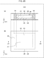
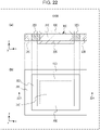
- Fig. 22 illustrates a schematic structure of a battery 6100 according to the sixth embodiment.
- Fig. 22(a) is an x-z diagram (22A cross-sectional view) illustrating the schematic structure of the battery 6100 according to the sixth embodiment.
- Fig. 22(b) is an x-y diagram (top perspective view) illustrating the schematic structure of the battery 6100 according to the sixth embodiment.
- the third region 330 may surround the second region 320.
- the density of the solid electrolyte material can be gradually increased from the center portion of the solid electrolyte layer 300 toward the outer rim portion (for example, the entire outer rim portion) on the four sides of the solid electrolyte layer 300.
- the matching and adhesion at the interfaces between contacting portions of the first region 310, the second region 320, and the third region 330 can be further improved in the outer rim portion (for example, the entire outer rim portion) on the four sides of the solid electrolyte layer 300.
- the heat generated in the center portion of the battery (for example, heat generated in the first region 310, the electrode layer 100, or the counter electrode layer 200) can be more easily dissipated to the third region 330 and the surface of the outer rim portion on the four sides of the solid electrolyte layer 300 (and the outside of the battery) through the second region 320.
- the third region 330 surrounds the second region 320 encompasses, for example, "the third region 330 contacts all of the end portions of the second region 320".
- the third region 330 may be in contact with all of the sides of this shape.
- the outer peripheral side surface of the second region 320 may be bonded to the inner peripheral side surface of the third region 330.
- Fig. 23 illustrates a schematic structure of a battery 6200 according to the sixth embodiment.
- Fig. 23(a) is an x-z diagram (23A cross-sectional view) illustrating the schematic structure of the battery 6200 according to the sixth embodiment.
- Fig. 23(b) is an x-y diagram (top perspective view) illustrating the schematic structure of the battery 6200 according to the sixth embodiment.
- the second region 320 may have a second projecting portion 321.
- the second projecting portion 321 is a portion that projects outward from the region where the electrode layer 100 and the counter electrode layer 200 face each other.
- the third region 330 may cover the second projecting portion 321.
- the contact area between the second region 320 and the third region 330 can be further increased.
- the heat from the center portion of the solid electrolyte layer 300 is easily transferred (dissipated) to the outer rim portion of the solid electrolyte layer 300.
- the heat generated in the center portion of the battery for example, heat generated in the first region 310, the electrode layer 100, or the counter electrode layer 200
- the heat generated in the center portion of the battery can be more easily dissipated to the surface of the solid electrolyte layer 300 (and the outside of the battery).
- Fig. 24 illustrates a schematic structure of a battery 6300 according to the sixth embodiment.
- Fig. 24(a) is an x-z diagram (24A cross-sectional view) illustrating the schematic structure of the battery 6300 according to the sixth embodiment.
- Fig. 24(b) is an x-y diagram (top perspective view) illustrating the schematic structure of the battery 6300 according to the sixth embodiment.
- the second projecting portion 321 may surround the region where the electrode layer 100 and the counter electrode layer 200 face each other.
- the third region 330 may cover the second projecting portion 321 exposing from around the region where the electrode layer 100 and the counter electrode layer 200 face each other.
- the contact area between the second region 320 and the third region 330 can be further increased.
- the heat from the center portion of the solid electrolyte layer 300 is easily transferred (dissipated) to the outer rim portion of the solid electrolyte layer 300 close to the parts where heat has been generated.
- the heat generated in the center portion of the battery for example, heat generated in the first region 310, the electrode layer 100, or the counter electrode layer 200
- the heat generated in the center portion of the battery can be more easily dissipated to the surface of the solid electrolyte layer 300 (and the outside of the battery).
- Fig. 25 illustrates a schematic structure of a battery 6400 according to the sixth embodiment.
- Fig. 25(a) is an x-z diagram (25A cross-sectional view) illustrating the schematic structure of the battery 6400 according to the sixth embodiment.
- Fig. 25(b) is an x-y diagram (top perspective view) illustrating the schematic structure of the battery 6400 according to the sixth embodiment.
- the first region 310 may have a first projecting portion 311.
- the first projecting portion 311 is a portion that projects outward from the region where the electrode layer 100 and the counter electrode layer 200 face each other.
- the second region 320 may cover the first projecting portion 311.
- the second region 320 covering the first projecting portion 311 may have a second projecting portion 321.
- the second projecting portion 321 is a portion that projects outward from the region where the electrode layer 100 and the counter electrode layer 200 face each other.
- the third region 330 may cover the second projecting portion 321.
- the contact area between the first region 310 and the second region 320 and the contact area between the second region 320 and the third region 330 can both be further increased.
- the heat from the center portion of the solid electrolyte layer 300 is easily transferred (dissipated) to the outer rim portion of the solid electrolyte layer 300.
- the heat generated in the center portion of the battery for example, heat generated in the first region 310, the electrode layer 100, or the counter electrode layer 200
- the third region 330 may be in contact with an end portion (for example, a side surface) of the electrode layer 100.
- the third region 330 which has a high solid electrolyte material density, can be disposed to be in contact with the outer rim portion (for example, at least one end portion) of the electrode layer 100.
- the heat from the electrode layer 100 is easily transferred (dissipated) to the third region 330.
- the heat generated in the center portion of the battery in other words, heat generated in the electrode layer 100
- the outer rim portion (for example, at least one end portion) of the electrode layer 100 can be covered with the third region 330 having a higher strength.
- breaking of the outer rim portion of the electrode layer 100 which has a relatively low strength (for example, collapse of the electrode material), can be suppressed by the third region 330.
- the strength of the battery can be further improved.
- the third region 330 having a higher solid electrolyte material density can be interposed between the outer rim portion of the electrode layer 100 and the outside of the battery (for example, outside air).
- the outside air for example, atmospheric air, humid air, or the like
- the environmental resistance of the battery can be further improved.
- the third region 330 may be in contact with only one end portion of the electrode layer 100.
- the electrode layer 100 has a rectangular shape (for example, a quadrilateral shape)
- the third region 330 may be disposed to be in contact with only one side of this shape.
- the third region 330 may be in contact with two or more end portions among the end portions of the electrode layer 100.
- the electrode layer 100 has a rectangular shape (for example, a quadrilateral shape)
- the third region 330 may be disposed to be in contact with two or more sides of this shape. In this manner, the heat dissipating property (and strength, environmental resistance, etc.) can be enhanced at the two or more end portions.
- the third region 330 may surround the electrode layer 100.
- the third region 330 which has a high solid electrolyte material density, can be disposed to be in contact with the outer rim portion on the four sides (for example, the entire outer rim portion) of the electrode layer 100.
- the heat from the electrode layer 100 is easily transferred (dissipated) to the third region 330 close to the parts where heat has been generated.
- the heat generated in the center portion of the battery in other words, heat generated in the electrode layer 100
- the outer rim portion on the four sides (for example, the entire outer rim) of the electrode layer 100 can be covered with the third region 330 having a higher strength.
- breaking of the outer rim portion of the electrode layer 100 which has a relatively low strength (for example, collapse of the electrode material), can be suppressed by the third region 330.
- the strength of the battery can be further improved.
- the third region 330 having a higher solid electrolyte material density can be interposed between the outer rim portion on the four sides of the electrode layer 100 and the outside of the battery (for example, outside air).
- the outside air for example, atmospheric air, humid air, or the like
- the environmental resistance of the battery can be further improved.
- the third region 330 may be in contact with an end portion (for example, a side surface) of the counter electrode layer 200.
- the third region 330 which has a high solid electrolyte material density, can be disposed to be in contact with the outer rim portion (for example, at least one end portion) of the counter electrode layer 200.
- the heat from the counter electrode layer 200 is easily transferred (dissipated) to the third region 330.
- the heat generated in the center portion of the battery in other words, heat generated in the counter electrode layer 200
- the outer rim portion (for example, at least one end portion) of the counter electrode layer 200 can be covered with the third region 330 having a higher strength.
- breaking of the outer rim portion of the counter electrode layer 200, which has a relatively low strength (for example, collapse of the counter electrode material) can be further suppressed by the third region 330.
- the strength of the battery can be further improved.
- the third region 330 having a higher solid electrolyte material density can be interposed between the outer rim portion of the counter electrode layer 200 and the outside of the battery (for example, outside air).
- the outside air for example, atmospheric air, humid air, or the like
- the environmental resistance of the battery can be further improved.
- the third region 330 may be in contact with only one end portion of the counter electrode layer 200.
- the third region 330 may be disposed to be in contact with only one side of this shape.
- the third region 330 may be in contact with two or more end portions among the end portions of the counter electrode layer 200.
- the third region 330 may be disposed to be in contact with two or more sides of this shape. In this manner, the heat dissipating property (and strength, environmental resistance, etc.) can be enhanced at the two or more end portions.
- the third region 330 may surround the counter electrode layer 200.
- the third region 330 which has a high solid electrolyte material density, can be disposed to be in contact with the outer rim portion on the four sides (for example, the entire outer rim portion) of the counter electrode layer 200.
- the heat from the counter electrode layer 200 is easily transferred (dissipated) to the third region 330 close to the parts where heat has been generated.
- the heat generated in the center portion of the battery in other words, heat generated in the counter electrode layer 200
- the outer rim portion on the four sides (for example, the entire outer rim) of the counter electrode layer 200 can be covered with the third region 330 having a higher strength.
- breaking of the outer rim portion on the four sides of the counter electrode layer 200, which has a relatively low strength (for example, collapse of the counter electrode material) can be further suppressed by the third region 330.
- the strength of the battery can be further improved.
- the third region 330 having a higher solid electrolyte material density can be interposed between the outer rim portion on the four sides of the counter electrode layer 200 and the outside of the battery (for example, outside air).
- the outside air for example, atmospheric air, humid air, or the like
- the environmental resistance of the battery can be further improved.
- the third region 330 surrounds the electrode layer 100 (or the counter electrode layer 200) encompasses, for example, “the third region 330 contacts all of the end portions of the electrode layer 100 (or the counter electrode layer 200)".
- the third region 330 may be in contact with all of the sides of this shape.
- Fig. 26 illustrates a schematic structure of a battery 6500 according to the sixth embodiment.
- Fig. 26(a) is an x-z diagram (26A cross-sectional view) illustrating the schematic structure of the battery 6500 according to the sixth embodiment.
- Fig. 26(b) is an x-y diagram (top perspective view) illustrating the schematic structure of the battery 6500 according to the sixth embodiment.
- a range in which the counter electrode layer 200 is formed may be larger than the range in which the electrode layer 100 is formed.
- the electrode layer 100 may be positioned within the range in which the counter electrode layer 200 is formed.
- the second region 320 may be in contact with an end portion of the electrode layer 100.
- the third region 330 may be in contact with an end portion of the counter electrode layer 200.
- the counter electrode layer 200 is formed to have a larger area than the electrode layer 100, precipitation of metal (for example, lithium) in the counter electrode layer 200 can be suppressed. Thus, short-circuiting between the electrode layer 100 and the counter electrode layer 200 caused by metal precipitation can be prevented.
- metal for example, lithium
- the third region 330 which has a high solid electrolyte material density, can be disposed to be in contact with the outer rim portion (for example, at least one end portion) of the counter electrode layer 200 while the counter electrode layer 200 is formed to have a larger area than the electrode layer 100 (in other words, while reducing the risk of short-circuiting due to the metal precipitation).
- the second region 320 which has a high solid electrolyte material density, can be disposed to be in contact with the outer rim portion (for example, at least one end portion) of the electrode layer 100 while the counter electrode layer 200 is formed to have a larger area than the electrode layer 100 (in other words, while reducing the risk of short-circuiting due to the metal precipitation).
- Fig. 27 illustrates a schematic structure of a battery 6600 according to the sixth embodiment.
- Fig. 27(a) is an x-z diagram (27A cross-sectional view) illustrating the schematic structure of the battery 6600 according to the sixth embodiment.
- Fig. 27(b) is an x-y diagram (top perspective view) illustrating the schematic structure of the battery 6600 according to the sixth embodiment.
- the second region 320 may surround the electrode layer 100.
- the third region 330 may surround the counter electrode layer 200.
- the third region 330 which has a high solid electrolyte material density, can be disposed to be in contact with the outer rim portion on the four sides (for example, the entire outer rim portion) of the counter electrode layer 200 while the counter electrode layer 200 is formed to have a larger area than the electrode layer 100 (in other words, while reducing the risk of short-circuiting due to the metal precipitation).
- the second region 320 which has a high solid electrolyte material density, can be disposed to be in contact with the outer rim portion on the four sides (for example, the entire outer rim portion) of the electrode layer 100 while the counter electrode layer 200 is formed to have a larger area than the electrode layer 100 (in other words, while reducing the risk of short-circuiting due to the metal precipitation).
- Fig. 28 illustrates a schematic structure of a battery 6700 according to the sixth embodiment.
- Fig. 28(a) is an x-z diagram (28A cross-sectional view) illustrating the schematic structure of the battery 6700 according to the sixth embodiment.
- Fig. 28(b) is an x-y diagram (top perspective view) illustrating the schematic structure of the battery 6700 according to the sixth embodiment.
- the first region 310 may surround the electrode layer 100.
- the second region 320 need not be in contact with the electrode layer 100.
- the area of the first region 310 positioned within the region where the electrode layer 100 and the counter electrode layer 200 face each other can be further increased.
- the area of the first region 310, which has a function of transferring metal ions, between the electrode layer 100 and the counter electrode layer 200 can be further increased. In this manner, precipitation of the metal (for example, lithium) in the counter electrode layer 200 can be further suppressed.
- Fig. 29 illustrates a schematic structure of a battery 7000 according to the seventh embodiment.
- Fig. 29(a) is an x-z diagram (29A cross-sectional view) illustrating the schematic structure of the battery 7000 according to the seventh embodiment.
- Fig. 29(b) is an x-y diagram (top perspective view) illustrating the schematic structure of the battery 7000 according to the seventh embodiment.
- the battery 7000 according to the seventh embodiment further includes the following features in addition to the features of the battery 6000 of the sixth embodiment described above.
- the battery 7000 of the seventh embodiment further includes an electrode current collector 400 and a counter electrode current collector 500.
- the electrode current collector 400 is a current collector electrically coupled to the electrode layer 100.
- the counter electrode current collector 500 is a current collector electrically coupled to the counter electrode layer 200.
- the third region 330 is positioned between the electrode current collector 400 and the counter electrode current collector 500 and is in contact with the electrode current collector 400 and the counter electrode current collector 500.
- the third region 330 which has a high solid electrolyte material density (in other words, a high strength), can function as a high-strength skeleton structure in the outer rim portion of the solid electrolyte layer 300 (in other words, the outer rim portion of the electrode current collector 400 and the counter electrode current collector 500).
- the third region 330 suppresses deformation or structural defects in the outer rim portion of the electrode current collector 400 and the counter electrode current collector 500.
- the battery has a large area and a reduced layer thickness (for example, a battery designed as a high-output, highcapacity battery) or when the battery is an all-solid battery not equipped with separators, short-circuiting caused by contact between the electrode current collector 400 and the counter electrode current collector 500 can be suppressed by the third region 330.
- the deformation resistance and impact resistance of the battery can be further enhanced.
- the third region 330 may be positioned within the region where the electrode current collector 400 and the counter electrode current collector 500 face each other without the electrode layer 100 and the counter electrode layer 200 therebetween among the region where the electrode current collector 400 and the counter electrode current collector 500 face each other.
- the third region 330 may be positioned at only one end portion of the electrode current collector 400 (and the counter electrode current collector 500).
- the electrode current collector 400 (and the counter electrode current collector 500) has a rectangular shape (for example, a quadrilateral shape)
- the third region 330 may be disposed at only one side of this shape.
- the third region 330 may be positioned at two or more end portions among the end portions of the electrode current collector 400 (and the counter electrode current collector 500).
- the electrode current collector 400 (and the counter electrode current collector 500) has a rectangular shape (for example, a quadrilateral shape)
- the third region 330 may be disposed at two or more sides of this shape. In this manner, short-circuiting caused by contact between the electrode current collector 400 and the counter electrode current collector 500 can be suppressed at two or more end portions.
- the third region 330 may surround the second region 320, the electrode layer 100, and the counter electrode layer 200.
- the third region 330 surrounding the second region 320, the electrode layer 100, and the counter electrode layer 200 may be in contact with the electrode current collector 400 and the counter electrode current collector 500. In this manner, short-circuiting caused by contact between the electrode current collector 400 and the counter electrode current collector 500 can be further suppressed around (for example, on the four sides of) the multilayer body constituted by the second region 320, the electrode layer 100, and the counter electrode layer 200.
- the third region 330 may be positioned within the entire region where the electrode current collector 400 and the counter electrode current collector 500 face each other without the electrode layer 100 and the counter electrode layer 200 therebetween among the region where the electrode current collector 400 and the counter electrode current collector 500 face each other. In this manner, short-circuiting caused by contact between the electrode current collector 400 and the counter electrode current collector 500 can be further suppressed around (for example, on the four sides of) the multilayer body constituted by the second region 320, the electrode layer 100, and the counter electrode layer 200.
- Fig. 30 illustrates a schematic structure of a battery 7100 according to the seventh embodiment.
- Fig. 30(a) is an x-z diagram (30A cross-sectional view) illustrating the schematic structure of the battery 7100 according to the seventh embodiment.
- Fig. 30(b) is an x-y diagram (top perspective view) illustrating the schematic structure of the battery 7100 according to the seventh embodiment.
- the second distance D2 may be smaller than the first distance D1.
- the third distance D3 may be smaller than the second distance D2.
- the first distance D1 is the distance between the electrode current collector 400 and the counter electrode current collector 500 at a position in which the first region 310 lies.
- the second distance D2 is the distance between the electrode current collector 400 and the counter electrode current collector 500 at a position in which the second region 320 lies.
- the third distance D3 is the distance between the electrode current collector 400 and the counter electrode current collector 500 at a position in which the third region 330 lies.
- a battery in which the outer rim portion of the solid electrolyte layer 300 (in other words, the outer rim portion of the electrode current collector 400 and the counter electrode current collector 500) is narrowed (in other words, a battery with narrowed outer peripheral side surfaces) can be configurated.
- the area of the exposed outer rim portion of the solid electrolyte layer 300 can be decreased.
- the outside air for example, atmospheric air, humid air, or the like
- the durability for example, the impact resistance
- the environmental resistance of the battery can be further improved.
- a portion (or the entirety) of side surfaces of the battery may be covered with an insulating material (for example, a sealing material).
- a sealing material may be, for example, a moisture-proof laminate sheet.
- the sealing material can prevent deterioration of the battery by moisture.
- the battery may be enclosed in a sealed case. Examples of the sealed case that can be used include common known battery cases (for example, laminate bags, metal cans, resin cases, etc.).
- the batteries of the first to seventh embodiments may each further include a pair of external electrodes.
- the pair of external electrodes may protrude outward from the upper and lower surfaces (or side surfaces) of the battery if the entire battery is to be sealed in with the sealing material.
- One of the external electrodes may be coupled to the current collector (for example, the electrode current collector 400) at one end of the battery.
- the other one of the external electrodes may be coupled to the current collector (for example, the counter electrode current collector 500) at the other end of the battery. In this manner, power can be discharged to the load coupled to the pair of external electrodes, and the battery can be charged by using a charger connected to the pair of external electrodes.
- pastes used for printing and forming the first region 310, the second region 320, the positive electrode layer, and the negative electrode layer are prepared.
- the pastes for the first region 310 and the second region 320 may be prepared from the same solid electrolyte material or different solid electrolyte materials.
- a glass powder of a Li 2 S-P 2 S 5 -based sulfide having an average particle diameter of about 10 ⁇ m and containing a triclinic crystal as a main component is prepared as the solid electrolyte material used as a mixture component for the first region 310, the second region 320, the positive electrode layer, and the negative electrode layer.
- a powder that has a high ion conductivity (for example, 2 to 3 ⁇ 10 -3 S/cm) when formed into a compact can be used as this powder.
- Solid electrolyte pastes prepared by adding an organic binder and a solvent to the glass powder and mixing and dispersing the resulting mixture are prepared as the pastes for forming the first region 310 and the second region 320.
- a powder of Li ⁇ Ni ⁇ Co ⁇ Al complex oxide (LiNi 0.8 Co 0.15 Al 0.05 O 2 ) having an average particle diameter of about 5 ⁇ m and having a layered structure is used as the positive electrode active material.
- a positive electrode layer paste composed of a mixture containing this active material and the glass powder described above is prepared in the same manner.
- a powder of natural graphite having an average particle diameter of about 10 ⁇ m is used as the negative electrode active material.
- a negative electrode layer paste composed of a mixture containing this active material and the glass powder described above is prepared in the same manner.
- copper foils having a thickness of about 30 ⁇ m to be used as the positive electrode current collector and the negative electrode current collector are prepared.
- the positive electrode layer paste and the negative electrode layer paste are respectively screen-printed onto surfaces of the copper foils while respectively drawing predetermined patterns so that the thickness of the paste applied is about 50 to 100 ⁇ m.
- the thickness decreases to 30 to 60 ⁇ m.
- current collectors (copper foils) on which a printed body that serves as a positive electrode layer and a printed body that serves as a negative electrode layer are respectively formed are obtained.
- the solid electrolyte paste described above is printed by using a metal mask onto each of the surfaces of the current collectors on which the printed body that serves as a positive electrode layer and a printed and the printed body that serves as a negative electrode layer are respectively formed, so that the thickness of the paste printed is about 100 ⁇ m. Then the printed paste is dried at 80 to 130°C.
- solid electrolyte material (20 GPa) ⁇ positive and negative electrode active materials (150 GPa)
- solid electrolyte material (20 GPa) ⁇ positive and negative electrode active materials (150 GPa)
- the Young's modulus of a typical sulfide-based solid electrolyte is 10 to 30 GPa.
- the Young's modulus of metals and oxides is 100 to 300 GPa.
- the dried films prepared from the pastes for the solid electrolyte layer, the positive electrode layer, and the negative electrode layer the dried films whose compaction rates between before and after pressurizing during stacking of the layers satisfy the relationship, "solid electrolyte (about 30%) > positive and negative electrode active materials (about 10%)" are used.
- the compaction properties of the printed bodies of the pastes can be controlled through the production process (for example, the design of the binder or the solvent, the drying method, etc.).
- pressure deformation also occurs; thus, the compaction rate can be easily increased by using the sulfide-based solid electrolyte.
- the relative density means the ratio relative to the theoretical density.
- the density (theoretical value) calculated from the unit cell of the crystal structure is 2.0 g/cm 3 .
- the density and conductivity of the first region 310 are 1.64 g/cm 3 and 2.2 ⁇ 10 -3 S/cm, respectively.
- the density and conductivity of the second region 320 are 1.8 g/cm 3 and 2.5 ⁇ 10 -3 S/cm, respectively.
- the density inside the battery can be confirmed through sectional observation with a SEM, for example.
- the conductivity can be evaluated through a microproperty analyzer such as a microprobe.
- the conductivity can be evaluated by preparing test samples having the same relative density.
- the first region 310 is the battery operation portion.
- the first region 310 is an operation region in which an electric current flows as a result of transfer of ions during charge and discharge of the battery.
- the conductivity of the first region 310 is preferably as high as possible.
- the second region 320 (and the third region 330) is the region that has relatively little involvement in the transfer of ions.
- the relationship, "conductivity of first region 310 ⁇ conductivity of second region 320" may be satisfied.
- the effective thermal conductivity changes in similar manner according to the density or conductivity by the increase in effective area and the increase in conductive carriers, which also function as thermal conduction carriers.
- the relationships regarding the density and the conductivity are reflected to the thermal conductivity.
- the relationship, "conductivity of first region 310 ⁇ conductivity of second region 320" is satisfied, the same relationship is satisfied for the thermal conductivity also.
- the effective conductivity and the thermal conductivity improve as the density increases (typically, the strength also increases).
- the sulfide-based solid electrolyte has a higher elastic modulus and pressure sinterabilty than typical inorganic materials.
- the density, conductivity, and strength can be improved over a wide range by increasing the packing rate (in other words, the density) by applying heat and/or pressure even when a powder compact is used.
- the relative density may be controlled to a value equal to or higher than the percolation threshold at which the conductivity increases steeply relative to the relative density.
- the first density may be equal to or higher than the percolation threshold.
- the conductivity relative to the increase in density improves gently.
- the relative density equal to or higher than the percolation threshold is suitable.
- the percolation threshold determined from the dependency of density and conductivity on pressure is at a relative density of about 70%.
- the first region 310 and the second region 320 are formed to have relative densities of 82% and 90%, respectively.
- the compaction rate of the solid electrolyte layer may be larger than the compaction rate of the positive electrode layer and the compaction rate of the negative electrode layer.
- the positive electrode layer and the negative electrode layer are hard and sparingly compactable layers.
- the second region 320 is soft and easily compactable.
- the first region 310 since the positive electrode layer and the negative electrode layer are present under and above along the pressure application axis, the pressure is absorbed and lost. Thus, an attenuated pressure is transferred to the second region 320. Thus, the second region 320 inevitably exhibits a lower density than the first region 310. Thus, the relationship, "second density > first density", is satisfied.
- the difference between the first density and the second density can be increased by setting the difference in the Young's modulus or the compaction rate of the constituent materials to be larger or by decreasing the hardness (or increasing the thickness) of the elastic sheet, for example.
- a structure in which the thickness of the first region 310 is smaller than the thickness of the second region 320 can be obtained.
- a battery having the third region 330 can be prepared by the above-described production method.
- the density relationship among the regions in the solid electrolyte layer can be realized by the following production methods as well as by one example of the production method described above.
- a paste for example, a paste with a high solid content
- the density of each paste can be adjusted by adjusting the amounts of the solid electrolyte material and other materials (for example, a binder) contained in the paste.
- These pastes with different densities may be respectively applied to the surfaces of the current collectors by printing. Subsequently, the resulting paste layers may be pressurized by a typical parallel plate rigid body to form a multilayer body (battery).
- the second region 320 (or the third region 330) may be selectively pressurized more strongly than the first region 310.
- a laminating press method that uses a die with recesses and protrusions may be used.
- the portion that will form the first region 310 may be punched out by a punching process. Subsequently, the paste for forming the first region 310 may be charged (or printed) into the recessed part formed thereby.
- the batteries indicated in the first to seventh embodiments described above can be prepared by adjusting the positions where the first region 310, the second region 320, and the third region 330 are formed.
- the battery according to the present disclosure can be used as the battery (for example, an all-solid secondary battery) used in various electronic devices, vehicles, etc.
Landscapes
- Chemical & Material Sciences (AREA)
- Chemical Kinetics & Catalysis (AREA)
- Electrochemistry (AREA)
- General Chemical & Material Sciences (AREA)
- Engineering & Computer Science (AREA)
- Manufacturing & Machinery (AREA)
- Inorganic Chemistry (AREA)
- Physics & Mathematics (AREA)
- General Physics & Mathematics (AREA)
- Condensed Matter Physics & Semiconductors (AREA)
- Secondary Cells (AREA)
- Materials Engineering (AREA)
- Algebra (AREA)
- Mathematical Analysis (AREA)
- Mathematical Optimization (AREA)
- Pure & Applied Mathematics (AREA)
- Connection Of Batteries Or Terminals (AREA)
- Battery Electrode And Active Subsutance (AREA)
Claims (21)
- Batterie, mit:einer Elektrodenschicht (100),einer Gegenelektrodenschicht (200), die eine Gegenelektrode für die Elektrodenschicht (100) ist, undeiner Festelektrolytschicht (300) zwischen der Elektrodenschicht (100) und der Gegenelektrodenschicht (200),wobei:die Festelektrolytschicht (300) einen ersten Bereich (310) mit einem ersten Festelektrolytmaterial und einem zweiten Bereich (320) mit einem zweiten Festelektrolytmaterial aufweist,der erste Bereich (310) innerhalb eines Bereichs positioniert ist, in dem die Elektrodenschicht (100) und die Gegenelektrodenschicht (200) einander gegenüberliegen,der zweite Bereich (320) hinsichtlich des ersten Bereichs (310) an einer äußeren Umfangsseite des Bereichs positioniert ist, in dem die Elektrodenschicht (100) und die Gegenelektrodenschicht (200) einander gegenüberliegen, und der zweite Bereich (320) in Kontakt mit dem ersten Bereich (310) ist, undeine zweite Dichte höher ist als eine erste Dichte,wobei die erste Dichte eine Dichte des ersten Festelektrolytmaterials in dem ersten Bereich (310) ist und die zweite Dichte eine Dichte des zweiten Festelektrolytmaterials in dem zweiten Bereich (320) ist,die Elektrodenschicht (100) ein Elektrodenaktivmaterial aufweist, unddie Gegenelektrodenschicht (200) ein Gegenelektrodenaktivmaterial aufweist,gekennzeichnet dadurch, dasssowohl eine Dichte des Elektrodenaktivmaterials und als auch eine Dichte des Gegenelektrodenaktivmaterials in dem ersten Bereich (310) jeweils geringer als die erste Dichte ist, undsowohl eine Dichte des Elektrodenaktivmaterials und als auch eine Dichte des Gegenelektrodenaktivmaterials in dem zweiten Bereich (320) jeweils geringer als die zweite Dichte ist.
- Batterie nach Anspruch 1, wobei der erste Bereich (310) und der zweite Bereich (320) nicht das Elektrodenaktivmaterial oder das Gegenelektrodenaktivmaterial aufweisen.
- Batterie nach Anspruch 1, wobei der zweite Bereich (320) den ersten Bereich (310) umgibt.
- Batterie nach Anspruch 1, wobei:der erste Bereich (310) einen ersten Vorsprungsabschnitt (311) aufweist, der auswärts von einem Bereich vorspringt, in dem die Elektrodenschicht (100) und die Gegenelektrodenschicht (200) einander gegenüberliegen, undder zweite Bereich (320) den ersten Vorsprungsabschnitt (311) bedeckt.
- Batterie nach Anspruch 1, wobei der zweite Bereich (320) mit einem Endabschnitt der Elektrodenschicht (100) in Kontakt ist.
- Batterie nach Anspruch 7, wobei der zweite Bereich (320) die Elektrodenschicht (100) umgibt.
- Batterie nach Anspruch 5, wobei der zweite Bereich (320) mit einem Endabschnitt der Gegenelektrodenschicht (200) in Kontakt ist.
- Batterie nach Anspruch 7, wobei der zweite Bereich (320) die Gegenelektrodenschicht (200) umgibt.
- Batterie nach Anspruch 1, ferner mit:einem Elektrodenstromkollektor (400), der elektrisch mit der Elektrodenschicht (100) gekoppelt ist, undeinem Gegenelektrodenstromkollektor (500), der elektrisch mit der Gegenelektrodenschicht (200) gekoppelt ist,wobei der zweite Bereich (320) zwischen dem Elektrodenstromkollektor (400) und dem Gegenelektrodenstromkollektor (500) eingeschlossen ist und in Kontakt mit dem Elektrodenstromkollektor (400) und dem Gegenelektrodenstromkollektor (500) ist.
- Batterie nach Anspruch 9, wobei, wenn eine Distanz zwischen dem Elektrodenstromkollektor (400) und dem Gegenelektrodenstromkollektor (500) an einer Position, an der sich der erste Bereich (310) befindet, als eine erste Distanz angenommen wird, undwenn eine Distanz zwischen dem Elektrodenstromkollektor (400) und dem Gegenelektrodenstromkollektor (500) an einer Position, an der sich der zweite Bereich (320) befindet, als eine zweite Distanz angenommen wird,eine zweite Distanz geringer ist als eine erste Distanz.
- Batterie nach Anspruch 1, wobei das erste Festelektrolytmaterial und das zweite Festelektrolytmaterial das gleiche Material sind.
- Batterie nach Anspruch 1, wobei:die Festelektrolytschicht (300) einen dritten Bereich (330) mit einem dritten Festelektrolytmaterial aufweist,der dritte Bereich (330) in Kontakt mit dem zweiten Bereich (320) ist,der zweite Bereich (320) zwischen dem ersten Bereich (310) und dem dritten Bereich (330) positioniert ist, undeine dritte Dichte höher ist als die zweite Dichte,wobei die dritte Dichte eine Dichte des dritten Festelektrolytmaterials in dem dritten Bereich (330) ist.
- Batterie nach Anspruch 12, wobei:
sowohl eine Dichte des Elektrodenaktivmaterials und als auch eine Dichte des Gegenelektrodenaktivmaterials in dem dritten Bereich (330) jeweils geringer als die dritte Dichte ist. - Batterie nach Anspruch 13, wobei der erste Bereich (310), der zweite Bereich (320) und der dritte Bereich (330) nicht das Elektrodenaktivmaterial oder das Gegenelektrodenaktivmaterial aufweisen.
- Batterie nach Anspruch 12, wobei der dritte Bereich (330) den zweiten Bereich (320) umgibt.
- Batterie nach Anspruch 12, wobei:der zweite Bereich (320) einen zweiten Vorsprungsabschnitt (321) aufweist, der auswärts von einem Bereich vorspringt, in dem die Elektrodenschicht (100) und die Gegenelektrodenschicht (200) einander gegenüberliegen, undder dritte Bereich (330) den zweiten Vorsprungsabschnitt (321) bedeckt.
- Batterie nach Anspruch 12, wobei:ein Bereich, in dem die Gegenelektrodenschicht (200) gebildet ist, größer ist als ein Bereich, in dem die Elektrodenschicht (100) gebildet ist,die Elektrodenschicht (100) innerhalb des Bereichs positioniert ist, in dem die Gegenelektrodenschicht (200) gebildet ist,der zweite Bereich (320) in Kontakt mit einem Endabschnitt der Elektrodenschicht (100) ist undder dritte Bereich (330) in Kontakt mit einem Endabschnitt der Gegenelektrodenschicht (200) ist.
- Batterie nach Anspruch 17, wobei:der zweite Bereich (320) die Elektrodenschicht (100) umgibt undder dritte Bereich (330) die Gegenelektrodenschicht (200) umgibt.
- Batterie nach Anspruch 12, ferner mit:einem Elektrodenstromkollektor (400), der elektrisch mit der Elektrodenschicht (100) gekoppelt ist, undeinem Gegenelektrodenstromkollektor (500), der elektrisch mit der Gegenelektrodenschicht (200) gekoppelt ist,wobei der dritte Bereich (330) zwischen dem Elektrodenstromkollektor (400) und dem Gegenelektrodenstromkollektor (500) eingeschlossen ist und in Kontakt mit dem Elektrodenstromkollektor (400) und dem Gegenelektrodenstromkollektor (500) ist.
- Batterie nach Anspruch 19, wobei:eine zweite Distanz geringer als eine erste Distanz ist, undeine dritte Distanz geringer als die zweite Distanz ist,wobei die erste Distanz eine Distanz zwischen dem Elektrodenstromkollektor (400) und dem Gegenelektrodenstromkollektor (500) an einer Position ist, an der sich der erste Bereich (310) befindet,die zweite Distanz eine Distanz zwischen den Elektrodenstromkollektor (400) und dem Gegenelektrodenstromkollektor (500) an einer Position ist, an der sich der zweite Bereich (320) befindet, unddie dritte Distanz eine Distanz zwischen dem Elektrodenstromkollektor (400) und dem Gegenelektrodenstromkollektor (500) an einer Position ist, an der sich der dritte Bereich (330) befindet.
- Batterie nach Anspruch 12, wobei das erste Festelektrolytmaterial, das zweite Festelektrolytmaterial und das dritte Festelektrolytmaterial das gleiche Material sind.
Priority Applications (1)
| Application Number | Priority Date | Filing Date | Title |
|---|---|---|---|
| EP22159772.7A EP4033577A1 (de) | 2017-07-25 | 2018-07-09 | Batterie |
Applications Claiming Priority (1)
| Application Number | Priority Date | Filing Date | Title |
|---|---|---|---|
| JP2017143358 | 2017-07-25 |
Related Child Applications (2)
| Application Number | Title | Priority Date | Filing Date |
|---|---|---|---|
| EP22159772.7A Division-Into EP4033577A1 (de) | 2017-07-25 | 2018-07-09 | Batterie |
| EP22159772.7A Division EP4033577A1 (de) | 2017-07-25 | 2018-07-09 | Batterie |
Publications (2)
| Publication Number | Publication Date |
|---|---|
| EP3435467A1 EP3435467A1 (de) | 2019-01-30 |
| EP3435467B1 true EP3435467B1 (de) | 2022-04-13 |
Family
ID=62904390
Family Applications (2)
| Application Number | Title | Priority Date | Filing Date |
|---|---|---|---|
| EP22159772.7A Pending EP4033577A1 (de) | 2017-07-25 | 2018-07-09 | Batterie |
| EP18182538.1A Active EP3435467B1 (de) | 2017-07-25 | 2018-07-09 | Batterie |
Family Applications Before (1)
| Application Number | Title | Priority Date | Filing Date |
|---|---|---|---|
| EP22159772.7A Pending EP4033577A1 (de) | 2017-07-25 | 2018-07-09 | Batterie |
Country Status (4)
| Country | Link |
|---|---|
| US (3) | US11509027B2 (de) |
| EP (2) | EP4033577A1 (de) |
| JP (4) | JP7157943B2 (de) |
| CN (2) | CN118263507A (de) |
Families Citing this family (9)
| Publication number | Priority date | Publication date | Assignee | Title |
|---|---|---|---|---|
| EP3876328A4 (de) * | 2018-10-29 | 2022-08-10 | Murata Manufacturing Co., Ltd. | Festkörperbatterie |
| JP7395290B2 (ja) * | 2019-08-30 | 2023-12-11 | キヤノン株式会社 | 固体電池用の電極および固体電池 |
| JP7395289B2 (ja) * | 2019-08-30 | 2023-12-11 | キヤノン株式会社 | 固体電池に適用される電極および固体電池 |
| WO2021039770A1 (ja) | 2019-08-30 | 2021-03-04 | キヤノン株式会社 | 固体電池に適用される電極および固体電池 |
| EP4033582A4 (de) * | 2019-09-17 | 2023-03-08 | Panasonic Intellectual Property Management Co., Ltd. | Batterie |
| JP7778525B2 (ja) * | 2021-10-22 | 2025-12-02 | 日産自動車株式会社 | 全固体電池 |
| KR102892910B1 (ko) * | 2022-12-26 | 2025-11-27 | 주식회사 엘지에너지솔루션 | 이차전지용 전극 제조 방법 및 장치 |
| WO2025253573A1 (ja) * | 2024-06-06 | 2025-12-11 | 日産自動車株式会社 | 全固体電池 |
| WO2026088265A1 (ja) * | 2024-10-21 | 2026-04-30 | 日産自動車株式会社 | 固体電池モジュール |
Family Cites Families (28)
| Publication number | Priority date | Publication date | Assignee | Title |
|---|---|---|---|---|
| JPH03235682A (ja) * | 1990-02-13 | 1991-10-21 | Hitachi Ltd | アルカリ金属熱電発電装置 |
| JP2001243977A (ja) * | 2000-03-01 | 2001-09-07 | Hitachi Ltd | ナトリウム硫黄電池、電池集合体およびモジュール |
| US7045234B2 (en) * | 2002-08-14 | 2006-05-16 | Hewlett-Packard Development Company, L.P. | Fuel-cell integral multifunction heater and methods |
| JP4066760B2 (ja) | 2002-09-26 | 2008-03-26 | 日産自動車株式会社 | バイポーラ電池 |
| US20080274411A1 (en) * | 2004-05-14 | 2008-11-06 | Junji Nakajima | Lithium Ion Secondary Battery |
| JP4274256B2 (ja) | 2006-08-25 | 2009-06-03 | トヨタ自動車株式会社 | 蓄電装置用電極及び蓄電装置 |
| JP4784485B2 (ja) * | 2006-11-02 | 2011-10-05 | トヨタ自動車株式会社 | リチウム二次電池 |
| JP4577659B2 (ja) * | 2006-11-15 | 2010-11-10 | トヨタ自動車株式会社 | 蓄電装置 |
| JP4311442B2 (ja) * | 2006-12-21 | 2009-08-12 | トヨタ自動車株式会社 | 蓄電装置 |
| JP5253785B2 (ja) * | 2007-10-23 | 2013-07-31 | パナソニック株式会社 | ドライポリマー電解質および全固体型ポリマー電池 |
| JP4478706B2 (ja) | 2007-09-05 | 2010-06-09 | セイコーエプソン株式会社 | リチウムイオン伝導性固体電解質およびそれを用いた全固体リチウム二次電池 |
| JP5245441B2 (ja) * | 2008-02-08 | 2013-07-24 | トヨタ自動車株式会社 | 固体型電池 |
| JP5413129B2 (ja) * | 2009-10-30 | 2014-02-12 | トヨタ自動車株式会社 | 固体電池の製造方法 |
| US20130323803A1 (en) | 2011-02-04 | 2013-12-05 | North Carolina State University | Methods and compositions for the production of extremophile enzymes from green microalgae and cyanobacteria |
| JP5677181B2 (ja) * | 2011-04-26 | 2015-02-25 | 京セラ株式会社 | 固体電解質およびそれを用いた二次電池 |
| JP2013016280A (ja) * | 2011-06-30 | 2013-01-24 | Sumitomo Electric Ind Ltd | 非水電解質電池 |
| JP5708527B2 (ja) * | 2012-02-24 | 2015-04-30 | トヨタ自動車株式会社 | 固体電池用電極層及び固体電池 |
| JP5447578B2 (ja) * | 2012-04-27 | 2014-03-19 | 株式会社豊田自動織機 | 固体電解質及び二次電池 |
| KR101382869B1 (ko) * | 2012-06-04 | 2014-04-08 | 현대자동차주식회사 | 배터리용 복합형 고체 고이온전도체 및 이를 이용한 리튬황배터리 |
| KR101420517B1 (ko) * | 2012-10-31 | 2014-07-16 | 삼성전기주식회사 | 적층 세라믹 캐패시터 및 이를 포함하는 인쇄회로기판 |
| JP2016018704A (ja) * | 2014-07-09 | 2016-02-01 | トヨタ自動車株式会社 | 全固体電池 |
| JP6576072B2 (ja) | 2015-03-31 | 2019-09-18 | 日立造船株式会社 | 全固体二次電池の製造方法 |
| JP6608188B2 (ja) * | 2015-06-23 | 2019-11-20 | 日立造船株式会社 | 全固体二次電池およびその製造方法 |
| JP6676399B2 (ja) * | 2015-10-05 | 2020-04-08 | 古河機械金属株式会社 | バイポーラ型リチウムイオン電池およびバイポーラ型リチウムイオン電池の製造方法 |
| CN107305961B (zh) * | 2016-04-25 | 2022-03-29 | 松下知识产权经营株式会社 | 电池、电池制造方法和电池制造装置 |
| CN108258358B (zh) * | 2016-12-28 | 2022-11-11 | 松下知识产权经营株式会社 | 电池 |
| JP7065323B2 (ja) * | 2017-02-09 | 2022-05-12 | パナソニックIpマネジメント株式会社 | 全固体電池およびその製造方法 |
| US10686213B2 (en) * | 2017-05-18 | 2020-06-16 | Panasonic Intellectual Property Management Co., Ltd. | Battery |
-
2018
- 2018-06-28 JP JP2018122862A patent/JP7157943B2/ja active Active
- 2018-07-09 EP EP22159772.7A patent/EP4033577A1/de active Pending
- 2018-07-09 EP EP18182538.1A patent/EP3435467B1/de active Active
- 2018-07-12 US US16/034,324 patent/US11509027B2/en active Active
- 2018-07-19 CN CN202410364144.9A patent/CN118263507A/zh active Pending
- 2018-07-19 CN CN201810793848.2A patent/CN109301308B/zh active Active
-
2022
- 2022-09-27 JP JP2022153794A patent/JP7466098B2/ja active Active
- 2022-10-20 US US17/970,166 patent/US11888158B2/en active Active
-
2023
- 2023-12-21 US US18/392,953 patent/US20240128450A1/en active Pending
-
2024
- 2024-03-19 JP JP2024043633A patent/JP7702656B2/ja active Active
-
2025
- 2025-06-06 JP JP2025094616A patent/JP2025116271A/ja active Pending
Also Published As
| Publication number | Publication date |
|---|---|
| JP7702656B2 (ja) | 2025-07-04 |
| US11888158B2 (en) | 2024-01-30 |
| CN109301308A (zh) | 2019-02-01 |
| JP7466098B2 (ja) | 2024-04-12 |
| US20190036089A1 (en) | 2019-01-31 |
| JP2025116271A (ja) | 2025-08-07 |
| CN118263507A (zh) | 2024-06-28 |
| JP7157943B2 (ja) | 2022-10-21 |
| EP4033577A1 (de) | 2022-07-27 |
| US20240128450A1 (en) | 2024-04-18 |
| US11509027B2 (en) | 2022-11-22 |
| EP3435467A1 (de) | 2019-01-30 |
| JP2022177249A (ja) | 2022-11-30 |
| JP2019029339A (ja) | 2019-02-21 |
| CN109301308B (zh) | 2024-04-09 |
| US20230039438A1 (en) | 2023-02-09 |
| JP2024075677A (ja) | 2024-06-04 |
Similar Documents
| Publication | Publication Date | Title |
|---|---|---|
| US11888158B2 (en) | Battery | |
| US20230411702A1 (en) | All-solid state secondary cell and production method for same | |
| JP5930035B2 (ja) | 全固体電池及びその製造方法 | |
| KR102564315B1 (ko) | 전고체 전지용 전극의 제조방법 및 전고체 전지의 제조방법 | |
| KR101716995B1 (ko) | 전고체 전지 및 그 제조 방법 | |
| JP5850154B2 (ja) | 全固体電池の製造方法 | |
| EP3675245B1 (de) | Negativelektrodenaktivmaterial, batterie und vorrichtung | |
| JP2014127272A (ja) | 全固体電池用電極体の製造方法 | |
| JP2016018704A (ja) | 全固体電池 | |
| JP7345263B2 (ja) | 全固体リチウム二次電池の製造方法 | |
| JP2021197204A (ja) | 電池 | |
| US20220223908A1 (en) | All-solid-state battery production method and all-solid-state battery | |
| CN113273015A (zh) | 全固体电池 | |
| JP2023548177A (ja) | 負極より面積が広い正極を含む全固体電池及びその製造方法 | |
| JP2023109298A (ja) | 正極 | |
| CN114696019A (zh) | 电池模块 | |
| JP7808783B2 (ja) | 電池 | |
| US20250253507A1 (en) | Electrode stack and battery | |
| KR102796773B1 (ko) | 전지 | |
| US20250253311A1 (en) | Solid-state battery and method for producing solid-state battery | |
| CN121076210A (zh) | 固体电池 |
Legal Events
| Date | Code | Title | Description |
|---|---|---|---|
| PUAI | Public reference made under article 153(3) epc to a published international application that has entered the european phase |
Free format text: ORIGINAL CODE: 0009012 |
|
| STAA | Information on the status of an ep patent application or granted ep patent |
Free format text: STATUS: THE APPLICATION HAS BEEN PUBLISHED |
|
| AK | Designated contracting states |
Kind code of ref document: A1 Designated state(s): AL AT BE BG CH CY CZ DE DK EE ES FI FR GB GR HR HU IE IS IT LI LT LU LV MC MK MT NL NO PL PT RO RS SE SI SK SM TR |
|
| AX | Request for extension of the european patent |
Extension state: BA ME |
|
| STAA | Information on the status of an ep patent application or granted ep patent |
Free format text: STATUS: REQUEST FOR EXAMINATION WAS MADE |
|
| 17P | Request for examination filed |
Effective date: 20190730 |
|
| RBV | Designated contracting states (corrected) |
Designated state(s): AL AT BE BG CH CY CZ DE DK EE ES FI FR GB GR HR HU IE IS IT LI LT LU LV MC MK MT NL NO PL PT RO RS SE SI SK SM TR |
|
| RIC1 | Information provided on ipc code assigned before grant |
Ipc: H01M 10/654 20140101ALI20210927BHEP Ipc: H01M 10/653 20140101ALI20210927BHEP Ipc: H01M 10/652 20140101ALI20210927BHEP Ipc: H01M 10/647 20140101ALI20210927BHEP Ipc: H01M 10/617 20140101ALI20210927BHEP Ipc: H01M 10/0585 20100101ALI20210927BHEP Ipc: H01M 10/0562 20100101ALI20210927BHEP Ipc: H01M 10/052 20100101AFI20210927BHEP |
|
| GRAP | Despatch of communication of intention to grant a patent |
Free format text: ORIGINAL CODE: EPIDOSNIGR1 |
|
| STAA | Information on the status of an ep patent application or granted ep patent |
Free format text: STATUS: GRANT OF PATENT IS INTENDED |
|
| INTG | Intention to grant announced |
Effective date: 20211109 |
|
| GRAS | Grant fee paid |
Free format text: ORIGINAL CODE: EPIDOSNIGR3 |
|
| GRAA | (expected) grant |
Free format text: ORIGINAL CODE: 0009210 |
|
| STAA | Information on the status of an ep patent application or granted ep patent |
Free format text: STATUS: THE PATENT HAS BEEN GRANTED |
|
| AK | Designated contracting states |
Kind code of ref document: B1 Designated state(s): AL AT BE BG CH CY CZ DE DK EE ES FI FR GB GR HR HU IE IS IT LI LT LU LV MC MK MT NL NO PL PT RO RS SE SI SK SM TR |
|
| REG | Reference to a national code |
Ref country code: GB Ref legal event code: FG4D |
|
| REG | Reference to a national code |
Ref country code: CH Ref legal event code: EP |
|
| REG | Reference to a national code |
Ref country code: DE Ref legal event code: R096 Ref document number: 602018033676 Country of ref document: DE |
|
| REG | Reference to a national code |
Ref country code: IE Ref legal event code: FG4D |
|
| REG | Reference to a national code |
Ref country code: AT Ref legal event code: REF Ref document number: 1484113 Country of ref document: AT Kind code of ref document: T Effective date: 20220515 |
|
| REG | Reference to a national code |
Ref country code: LT Ref legal event code: MG9D |
|
| REG | Reference to a national code |
Ref country code: NL Ref legal event code: MP Effective date: 20220413 |
|
| REG | Reference to a national code |
Ref country code: AT Ref legal event code: MK05 Ref document number: 1484113 Country of ref document: AT Kind code of ref document: T Effective date: 20220413 |
|
| PG25 | Lapsed in a contracting state [announced via postgrant information from national office to epo] |
Ref country code: NL Free format text: LAPSE BECAUSE OF FAILURE TO SUBMIT A TRANSLATION OF THE DESCRIPTION OR TO PAY THE FEE WITHIN THE PRESCRIBED TIME-LIMIT Effective date: 20220413 |
|
| PG25 | Lapsed in a contracting state [announced via postgrant information from national office to epo] |
Ref country code: SE Free format text: LAPSE BECAUSE OF FAILURE TO SUBMIT A TRANSLATION OF THE DESCRIPTION OR TO PAY THE FEE WITHIN THE PRESCRIBED TIME-LIMIT Effective date: 20220413 Ref country code: PT Free format text: LAPSE BECAUSE OF FAILURE TO SUBMIT A TRANSLATION OF THE DESCRIPTION OR TO PAY THE FEE WITHIN THE PRESCRIBED TIME-LIMIT Effective date: 20220816 Ref country code: NO Free format text: LAPSE BECAUSE OF FAILURE TO SUBMIT A TRANSLATION OF THE DESCRIPTION OR TO PAY THE FEE WITHIN THE PRESCRIBED TIME-LIMIT Effective date: 20220713 Ref country code: LT Free format text: LAPSE BECAUSE OF FAILURE TO SUBMIT A TRANSLATION OF THE DESCRIPTION OR TO PAY THE FEE WITHIN THE PRESCRIBED TIME-LIMIT Effective date: 20220413 Ref country code: HR Free format text: LAPSE BECAUSE OF FAILURE TO SUBMIT A TRANSLATION OF THE DESCRIPTION OR TO PAY THE FEE WITHIN THE PRESCRIBED TIME-LIMIT Effective date: 20220413 Ref country code: GR Free format text: LAPSE BECAUSE OF FAILURE TO SUBMIT A TRANSLATION OF THE DESCRIPTION OR TO PAY THE FEE WITHIN THE PRESCRIBED TIME-LIMIT Effective date: 20220714 Ref country code: FI Free format text: LAPSE BECAUSE OF FAILURE TO SUBMIT A TRANSLATION OF THE DESCRIPTION OR TO PAY THE FEE WITHIN THE PRESCRIBED TIME-LIMIT Effective date: 20220413 Ref country code: ES Free format text: LAPSE BECAUSE OF FAILURE TO SUBMIT A TRANSLATION OF THE DESCRIPTION OR TO PAY THE FEE WITHIN THE PRESCRIBED TIME-LIMIT Effective date: 20220413 Ref country code: BG Free format text: LAPSE BECAUSE OF FAILURE TO SUBMIT A TRANSLATION OF THE DESCRIPTION OR TO PAY THE FEE WITHIN THE PRESCRIBED TIME-LIMIT Effective date: 20220713 Ref country code: AT Free format text: LAPSE BECAUSE OF FAILURE TO SUBMIT A TRANSLATION OF THE DESCRIPTION OR TO PAY THE FEE WITHIN THE PRESCRIBED TIME-LIMIT Effective date: 20220413 |
|
| PG25 | Lapsed in a contracting state [announced via postgrant information from national office to epo] |
Ref country code: RS Free format text: LAPSE BECAUSE OF FAILURE TO SUBMIT A TRANSLATION OF THE DESCRIPTION OR TO PAY THE FEE WITHIN THE PRESCRIBED TIME-LIMIT Effective date: 20220413 Ref country code: PL Free format text: LAPSE BECAUSE OF FAILURE TO SUBMIT A TRANSLATION OF THE DESCRIPTION OR TO PAY THE FEE WITHIN THE PRESCRIBED TIME-LIMIT Effective date: 20220413 Ref country code: LV Free format text: LAPSE BECAUSE OF FAILURE TO SUBMIT A TRANSLATION OF THE DESCRIPTION OR TO PAY THE FEE WITHIN THE PRESCRIBED TIME-LIMIT Effective date: 20220413 Ref country code: IS Free format text: LAPSE BECAUSE OF FAILURE TO SUBMIT A TRANSLATION OF THE DESCRIPTION OR TO PAY THE FEE WITHIN THE PRESCRIBED TIME-LIMIT Effective date: 20220813 |
|
| REG | Reference to a national code |
Ref country code: DE Ref legal event code: R097 Ref document number: 602018033676 Country of ref document: DE |
|
| PG25 | Lapsed in a contracting state [announced via postgrant information from national office to epo] |
Ref country code: SM Free format text: LAPSE BECAUSE OF FAILURE TO SUBMIT A TRANSLATION OF THE DESCRIPTION OR TO PAY THE FEE WITHIN THE PRESCRIBED TIME-LIMIT Effective date: 20220413 Ref country code: SK Free format text: LAPSE BECAUSE OF FAILURE TO SUBMIT A TRANSLATION OF THE DESCRIPTION OR TO PAY THE FEE WITHIN THE PRESCRIBED TIME-LIMIT Effective date: 20220413 Ref country code: RO Free format text: LAPSE BECAUSE OF FAILURE TO SUBMIT A TRANSLATION OF THE DESCRIPTION OR TO PAY THE FEE WITHIN THE PRESCRIBED TIME-LIMIT Effective date: 20220413 Ref country code: EE Free format text: LAPSE BECAUSE OF FAILURE TO SUBMIT A TRANSLATION OF THE DESCRIPTION OR TO PAY THE FEE WITHIN THE PRESCRIBED TIME-LIMIT Effective date: 20220413 Ref country code: DK Free format text: LAPSE BECAUSE OF FAILURE TO SUBMIT A TRANSLATION OF THE DESCRIPTION OR TO PAY THE FEE WITHIN THE PRESCRIBED TIME-LIMIT Effective date: 20220413 Ref country code: CZ Free format text: LAPSE BECAUSE OF FAILURE TO SUBMIT A TRANSLATION OF THE DESCRIPTION OR TO PAY THE FEE WITHIN THE PRESCRIBED TIME-LIMIT Effective date: 20220413 |
|
| PLBE | No opposition filed within time limit |
Free format text: ORIGINAL CODE: 0009261 |
|
| STAA | Information on the status of an ep patent application or granted ep patent |
Free format text: STATUS: NO OPPOSITION FILED WITHIN TIME LIMIT |
|
| PG25 | Lapsed in a contracting state [announced via postgrant information from national office to epo] |
Ref country code: MC Free format text: LAPSE BECAUSE OF FAILURE TO SUBMIT A TRANSLATION OF THE DESCRIPTION OR TO PAY THE FEE WITHIN THE PRESCRIBED TIME-LIMIT Effective date: 20220413 |
|
| REG | Reference to a national code |
Ref country code: CH Ref legal event code: PL |
|
| 26N | No opposition filed |
Effective date: 20230116 |
|
| GBPC | Gb: european patent ceased through non-payment of renewal fee |
Effective date: 20220713 |
|
| REG | Reference to a national code |
Ref country code: BE Ref legal event code: MM Effective date: 20220731 |
|
| PG25 | Lapsed in a contracting state [announced via postgrant information from national office to epo] |
Ref country code: AL Free format text: LAPSE BECAUSE OF FAILURE TO SUBMIT A TRANSLATION OF THE DESCRIPTION OR TO PAY THE FEE WITHIN THE PRESCRIBED TIME-LIMIT Effective date: 20220413 |
|
| PG25 | Lapsed in a contracting state [announced via postgrant information from national office to epo] |
Ref country code: LU Free format text: LAPSE BECAUSE OF NON-PAYMENT OF DUE FEES Effective date: 20220709 Ref country code: LI Free format text: LAPSE BECAUSE OF NON-PAYMENT OF DUE FEES Effective date: 20220731 Ref country code: FR Free format text: LAPSE BECAUSE OF NON-PAYMENT OF DUE FEES Effective date: 20220731 Ref country code: CH Free format text: LAPSE BECAUSE OF NON-PAYMENT OF DUE FEES Effective date: 20220731 |
|
| PG25 | Lapsed in a contracting state [announced via postgrant information from national office to epo] |
Ref country code: SI Free format text: LAPSE BECAUSE OF FAILURE TO SUBMIT A TRANSLATION OF THE DESCRIPTION OR TO PAY THE FEE WITHIN THE PRESCRIBED TIME-LIMIT Effective date: 20220413 Ref country code: GB Free format text: LAPSE BECAUSE OF NON-PAYMENT OF DUE FEES Effective date: 20220713 Ref country code: BE Free format text: LAPSE BECAUSE OF NON-PAYMENT OF DUE FEES Effective date: 20220731 |
|
| PG25 | Lapsed in a contracting state [announced via postgrant information from national office to epo] |
Ref country code: IE Free format text: LAPSE BECAUSE OF NON-PAYMENT OF DUE FEES Effective date: 20220709 |
|
| PG25 | Lapsed in a contracting state [announced via postgrant information from national office to epo] |
Ref country code: IT Free format text: LAPSE BECAUSE OF FAILURE TO SUBMIT A TRANSLATION OF THE DESCRIPTION OR TO PAY THE FEE WITHIN THE PRESCRIBED TIME-LIMIT Effective date: 20220413 |
|
| PG25 | Lapsed in a contracting state [announced via postgrant information from national office to epo] |
Ref country code: HU Free format text: LAPSE BECAUSE OF FAILURE TO SUBMIT A TRANSLATION OF THE DESCRIPTION OR TO PAY THE FEE WITHIN THE PRESCRIBED TIME-LIMIT; INVALID AB INITIO Effective date: 20180709 |
|
| PG25 | Lapsed in a contracting state [announced via postgrant information from national office to epo] |
Ref country code: MK Free format text: LAPSE BECAUSE OF FAILURE TO SUBMIT A TRANSLATION OF THE DESCRIPTION OR TO PAY THE FEE WITHIN THE PRESCRIBED TIME-LIMIT Effective date: 20220413 Ref country code: CY Free format text: LAPSE BECAUSE OF FAILURE TO SUBMIT A TRANSLATION OF THE DESCRIPTION OR TO PAY THE FEE WITHIN THE PRESCRIBED TIME-LIMIT Effective date: 20220413 |
|
| PG25 | Lapsed in a contracting state [announced via postgrant information from national office to epo] |
Ref country code: TR Free format text: LAPSE BECAUSE OF FAILURE TO SUBMIT A TRANSLATION OF THE DESCRIPTION OR TO PAY THE FEE WITHIN THE PRESCRIBED TIME-LIMIT Effective date: 20220413 |
|
| PG25 | Lapsed in a contracting state [announced via postgrant information from national office to epo] |
Ref country code: MT Free format text: LAPSE BECAUSE OF FAILURE TO SUBMIT A TRANSLATION OF THE DESCRIPTION OR TO PAY THE FEE WITHIN THE PRESCRIBED TIME-LIMIT Effective date: 20220413 |
|
| PG25 | Lapsed in a contracting state [announced via postgrant information from national office to epo] |
Ref country code: BG Free format text: LAPSE BECAUSE OF FAILURE TO SUBMIT A TRANSLATION OF THE DESCRIPTION OR TO PAY THE FEE WITHIN THE PRESCRIBED TIME-LIMIT Effective date: 20220413 |
|
| PG25 | Lapsed in a contracting state [announced via postgrant information from national office to epo] |
Ref country code: BG Free format text: LAPSE BECAUSE OF FAILURE TO SUBMIT A TRANSLATION OF THE DESCRIPTION OR TO PAY THE FEE WITHIN THE PRESCRIBED TIME-LIMIT Effective date: 20220413 |
|
| PGFP | Annual fee paid to national office [announced via postgrant information from national office to epo] |
Ref country code: DE Payment date: 20250722 Year of fee payment: 8 |