EP3434342B1 - Spielsystem, zubehör, spielprogramm und spielverarbeitungsverfahren - Google Patents
Spielsystem, zubehör, spielprogramm und spielverarbeitungsverfahren Download PDFInfo
- Publication number
- EP3434342B1 EP3434342B1 EP18180102.8A EP18180102A EP3434342B1 EP 3434342 B1 EP3434342 B1 EP 3434342B1 EP 18180102 A EP18180102 A EP 18180102A EP 3434342 B1 EP3434342 B1 EP 3434342B1
- Authority
- EP
- European Patent Office
- Prior art keywords
- game
- controller
- accessory
- game controller
- fixing portion
- Prior art date
- Legal status (The legal status is an assumption and is not a legal conclusion. Google has not performed a legal analysis and makes no representation as to the accuracy of the status listed.)
- Active
Links
Images


Classifications
-
- A—HUMAN NECESSITIES
- A63—SPORTS; GAMES; AMUSEMENTS
- A63F—CARD, BOARD, OR ROULETTE GAMES; INDOOR GAMES USING SMALL MOVING PLAYING BODIES; VIDEO GAMES; GAMES NOT OTHERWISE PROVIDED FOR
- A63F13/00—Video games, i.e. games using an electronically generated display having two or more dimensions
- A63F13/20—Input arrangements for video game devices
- A63F13/21—Input arrangements for video game devices characterised by their sensors, purposes or types
- A63F13/211—Input arrangements for video game devices characterised by their sensors, purposes or types using inertial sensors, e.g. accelerometers or gyroscopes
-
- A—HUMAN NECESSITIES
- A63—SPORTS; GAMES; AMUSEMENTS
- A63F—CARD, BOARD, OR ROULETTE GAMES; INDOOR GAMES USING SMALL MOVING PLAYING BODIES; VIDEO GAMES; GAMES NOT OTHERWISE PROVIDED FOR
- A63F13/00—Video games, i.e. games using an electronically generated display having two or more dimensions
- A63F13/20—Input arrangements for video game devices
- A63F13/23—Input arrangements for video game devices for interfacing with the game device, e.g. specific interfaces between game controller and console
-
- A—HUMAN NECESSITIES
- A63—SPORTS; GAMES; AMUSEMENTS
- A63F—CARD, BOARD, OR ROULETTE GAMES; INDOOR GAMES USING SMALL MOVING PLAYING BODIES; VIDEO GAMES; GAMES NOT OTHERWISE PROVIDED FOR
- A63F13/00—Video games, i.e. games using an electronically generated display having two or more dimensions
- A63F13/20—Input arrangements for video game devices
- A63F13/24—Constructional details thereof, e.g. game controllers with detachable joystick handles
-
- A—HUMAN NECESSITIES
- A63—SPORTS; GAMES; AMUSEMENTS
- A63F—CARD, BOARD, OR ROULETTE GAMES; INDOOR GAMES USING SMALL MOVING PLAYING BODIES; VIDEO GAMES; GAMES NOT OTHERWISE PROVIDED FOR
- A63F13/00—Video games, i.e. games using an electronically generated display having two or more dimensions
- A63F13/40—Processing input control signals of video game devices, e.g. signals generated by the player or derived from the environment
- A63F13/42—Processing input control signals of video game devices, e.g. signals generated by the player or derived from the environment by mapping the input signals into game commands, e.g. mapping the displacement of a stylus on a touch screen to the steering angle of a virtual vehicle
- A63F13/428—Processing input control signals of video game devices, e.g. signals generated by the player or derived from the environment by mapping the input signals into game commands, e.g. mapping the displacement of a stylus on a touch screen to the steering angle of a virtual vehicle involving motion or position input signals, e.g. signals representing the rotation of an input controller or a player's arm motions sensed by accelerometers or gyroscopes
-
- A—HUMAN NECESSITIES
- A63—SPORTS; GAMES; AMUSEMENTS
- A63F—CARD, BOARD, OR ROULETTE GAMES; INDOOR GAMES USING SMALL MOVING PLAYING BODIES; VIDEO GAMES; GAMES NOT OTHERWISE PROVIDED FOR
- A63F13/00—Video games, i.e. games using an electronically generated display having two or more dimensions
- A63F13/90—Constructional details or arrangements of video game devices not provided for in groups A63F13/20 or A63F13/25, e.g. housing, wiring, connections or cabinets
- A63F13/98—Accessories, i.e. detachable arrangements optional for the use of the video game device, e.g. grip supports of game controllers
-
- A—HUMAN NECESSITIES
- A63—SPORTS; GAMES; AMUSEMENTS
- A63F—CARD, BOARD, OR ROULETTE GAMES; INDOOR GAMES USING SMALL MOVING PLAYING BODIES; VIDEO GAMES; GAMES NOT OTHERWISE PROVIDED FOR
- A63F13/00—Video games, i.e. games using an electronically generated display having two or more dimensions
- A63F13/20—Input arrangements for video game devices
- A63F13/24—Constructional details thereof, e.g. game controllers with detachable joystick handles
- A63F13/245—Constructional details thereof, e.g. game controllers with detachable joystick handles specially adapted to a particular type of game, e.g. steering wheels
-
- A—HUMAN NECESSITIES
- A63—SPORTS; GAMES; AMUSEMENTS
- A63F—CARD, BOARD, OR ROULETTE GAMES; INDOOR GAMES USING SMALL MOVING PLAYING BODIES; VIDEO GAMES; GAMES NOT OTHERWISE PROVIDED FOR
- A63F13/00—Video games, i.e. games using an electronically generated display having two or more dimensions
- A63F13/90—Constructional details or arrangements of video game devices not provided for in groups A63F13/20 or A63F13/25, e.g. housing, wiring, connections or cabinets
- A63F13/92—Video game devices specially adapted to be hand-held while playing
Definitions
- the present invention relates to a game system, an accessory, a game program, and a game processing method for performing game processing using a plurality of game controllers.
- EP 3 103 534 A2 (NINTENDO CO LTD [JP]), 14 December 2016 (2016-12-14), relates to an information processing system, information processing device, controller device and accessory.
- US 2012/0040758 A1 (HOVSETH LAWRENCE D [US]), 16 February 2012 (2012-02-16), relates to a video game accessory.
- EP 2 177 250 A2 (NINTENDO CO LTD [JP]), 21 April 2010 (2010-04-21), relates to a game apparatus and computer-readable storage medium having game program stored therein.
- Patent Literature 1 discloses a technique for attaching an elastic member having a spherical surface as an accessory to a lower end portion of a game controller.
- the present invention can employ, for example, the following configurations. It should be noted that it is understood that, to interpret the descriptions of the claims, the scope of the claims should be interpreted only by the descriptions of the claims. If there is a conflict between the descriptions of the claims and the descriptions of the specification, the descriptions of the claims take precedence.
- first game controller and the second game controller are attached to the accessory, whereby the first game controller is attached so as to rotate about at least a predetermined axis relative to the accessory.
- the difference value between the first value indicating the orientation of the first game controller and the second value indicating the orientation of the second game controller is calculated, and both controllers are attached to the accessory, whereby it is possible to easily extract a rotational action of the first game controller about the predetermined axis in the accessory.
- the game processing means may further comprise second game processing means for, based on the orientation of the first game controller or the orientation of the second game controller, executing a second game process different from the first game process.
- game processing can be performed not only based on the difference value but also based on the orientation of the first game controller or the orientation of the second game controller.
- game processing can be performed not only based on the difference value but also based on the orientation of the first game controller or the orientation of the second game controller.
- the second game process may be a process of performing orientation control for controlling an orientation of a game object based on at least one of the orientation of the first game controller and the orientation of the second game controller.
- the first game process may be a process of, based on the difference value, controlling a motion of the game object in a manner different from the orientation control.
- the first game process may be a process of, based on the difference value, controlling at least one of a moving velocity, an acceleration, and a moving distance of the game object in a virtual space.
- the second fixing portion may fix the second game controller so that the second game controller does not rotate about an axis parallel to or approximately parallel to the certain axis.
- first fixing portion may fix the first game controller so that the first game controller rotates about the certain axis relative to the second game controller fixed to the second fixing portion.
- the accessory may further comprise a biasing portion.
- the a biasing portion when the first game controller fixed to the first fixing portion rotates in a first direction about the certain axis, biases the first game controller so as to rotate in a direction opposite to the first direction.
- the accessory may further comprise a first rotation restriction portion. Then first rotation restriction portion restricts rotation so that the first game controller fixed to the first fixing portion does not rotate in a direction opposite to the first direction beyond a first angle.
- the accessory may further comprise a second rotation restriction portion.
- the second rotation restriction portion restricts rotation so that the first game controller fixed to the first fixing portion does not rotate in the first direction beyond a second angle.
- the biasing portion may bias the first game controller so as to rotate toward the first angle.
- the accessory may further comprise a main body portion.
- a display screen is attached to the main body portion.
- a first side surface and a second side surface may be formed to the left and right of an attachment position of the display screen.
- the first fixing portion may be on the first side surface side.
- the second fixing portion may be on the second side surface side.
- the accessory may further comprise a supporting portion.
- the supporting portion supports the main body portion.
- the main body portion may rotate together with the first fixing portion and the second fixing portion about the supporting portion.
- the accessory may further comprise a shaft portion.
- the shaft portion rotates the first fixing portion and the second fixing portion together.
- first fixing portion may be on one side of the accessory.
- the second fixing portion may be on the other side of the accessory, which is the opposite side of the first fixing portion.
- each of the first game controller and the second game controller may have a longitudinal shape.
- the first fixing portion and the second fixing portion may be in the accessory such that a longitudinal direction of the first game controller fixed to the first fixing portion and a longitudinal direction of the second game controller fixed to the second fixing portion are parallel or approximately parallel to each other.
- first fixing portion and the second fixing portion may be in the accessory such that longitudinal directions of the first fixing portion and the second fixing portion are on the same straight line or approximately the same straight line in the accessory.
- the game system comprises a game apparatus.
- the game apparatus comprises the game processing means and a display screen configured to display a game screen generated based on a processing result of the game processing means.
- the accessory further comprises a game apparatus fixing portion to which the game apparatus is attachably and detachably fixed.
- first game controller and the second game controller further may comprise a first button.
- the accessory may further comprise a movable portion.
- the movable portion may comprise an operation portion and a first button pressing portion.
- the operation portion is operated by a hand of a user.
- the first button pressing portion moves toward the first button in accordance with an operation on the operation portion, thereby pressing the first button of the first game controller fixed to the first fixing portion or the first button of the second game controller fixed to the second fixing portion.
- At least one of the first game controller and the second game controller may further comprise a second button.
- the movable portion may comprise a second button pressing portion. The second button pressing portion moves toward the second button in accordance with an operation on the operation portion, thereby pressing the second button of the first game controller fixed to the first fixing portion or the second button of the second game controller fixed to the second fixing portion.
- the first button pressing portion may press the first button.
- the second button pressing portion may press the second button.
- a first game controller comprising a first gyro sensor and a second game controller comprising a second gyro sensor are attachable and detachable.
- the accessory comprises a first fixing portion and a second fixing portion.
- the first fixing portion fixes the first game controller so as to rotate about at least a certain axis.
- the second fixing portion fixes the second game controller.
- a first game controller and a second game controller are attached to an accessory, whereby the first game controller is attached so as to rotate about at least a predetermined axis relative to the accessory.
- both controllers are attached to the accessory, whereby it is possible to easily extract a rotational action of the first game controller about the predetermined axis in the accessory. It is possible to perform game processing based on the content of the rotational action.
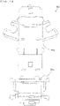
- first fixing portion and the second fixing portion may be configured to be formed by folding at least one cardboard.
- a game system comprises a first game controller comprising a first gyro sensor, a second game controller comprising a second gyro sensor, and a computer configured to execute game processing.
- the game system further comprises a computer configured to: based on an output from the first gyro sensor of the first game controller, calculate a first value indicating an orientation of the first game controller; based on an output from the second gyro sensor of the second game controller, calculate a second value indicating an orientation of the second game controller; and calculate a difference value indicating a difference between the first value and the second value.
- the computer configured to execute the game processing executes a first game process based on the difference value, and executes a second game process different from the first game process based on the orientation of the first game controller or the orientation of the second game controller.
- the game system may be carried out in the forms of a game program, a game apparatus, and a game method.
- a cardboard member can form an accessory to and from which a first game controller comprising a first gyro sensor and a second game controller comprising a second gyro sensor are attachable and detachable.
- the accessory comprises a first fixing portion and a second fixing portion.
- the first fixing portion fixes the first game controller so as to rotate about at least a certain axis.
- the second fixing portion fixes the second game controller.
- the cardboard member can integrally form the accessory comprising the first fixing portion and the second fixing portion, by folding the cardboard member.
- a cardboard member is folded, whereby it is possible to configure an accessory to which a first game controller and a second game controller are attachable.
- a game system 1 includes a main body apparatus (an information processing apparatus; which functions as a game apparatus main body in the exemplary embodiment) 2, a left controller 3, a right controller 4, and an accessory 200.
- a main body apparatus an information processing apparatus; which functions as a game apparatus main body in the exemplary embodiment
- a left controller 3 and the right controller 4 is attachable to and detachable from the main body apparatus 2. That is, the game system 1 can be used as a unified apparatus obtained by attaching each of the left controller 3 and the right controller 4 to the main body apparatus 2.
- the main body apparatus 2, the left controller 3, and the right controller 4 can also be used as separate bodies (see FIG. 2 ).
- the accessory 200 in the game system 1 can be used as an extension operation device or an operation tool by attaching controllers (e.g., the left controller 3 and the right controller 4) to the inside of the accessory 200.
- controllers e.g., the left controller 3 and the right controller 4
- the hardware configuration of the game system 1 according to the exemplary embodiment is described, and then, the control of the game system 1 according to the exemplary embodiment is described.
- FIG. 1 is a diagram showing an example of the state where the left controller 3 and the right controller 4 are attached to the main body apparatus 2. As shown in FIG. 1 , each of the left controller 3 and the right controller 4 is attached to and unified with the main body apparatus 2.
- the main body apparatus 2 is an apparatus for performing various processes (e.g., game processing) in the game system 1.
- the main body apparatus 2 includes a display 12.
- Each of the left controller 3 and the right controller 4 is an apparatus including operation sections with which a user provides inputs.
- the longitudinal direction of a main surface of the game system 1 is referred to as a "horizontal direction” (also as a “left-right direction”)
- the short direction of the main surface is referred to as a “vertical direction” (also as an “up-down direction”)
- a direction perpendicular to the main surface is referred to as a depth direction (also as a "front-back direction”).
- three axial (xyz axes) directions are defined for the game system 1. Specifically, as shown in FIG.
- the depth direction of the display 12 from a front surface, on which the display 12 is provided, to a back surface is defined as a positive z-axis direction.
- the direction from the right to left is defined as a positive x-axis direction.
- the direction upward along the display 12 is defined as a positive y-axis direction.
- FIG. 2 is a diagram showing an example of the state where each of the left controller 3 and the right controller 4 is detached from the main body apparatus 2.
- the left controller 3 and the right controller 4 are attachable to and detachable from the main body apparatus 2.
- the left controller 3 and the right controller 4 will occasionally be referred to collectively as a "controller”.
- two controllers e.g., the left controller 3 and the right controller 4
- an extension operation device e.g., the accessory 200
- control information processing e.g., game processing
- FIG. 3 is six orthogonal views showing an example of the main body apparatus 2.
- the main body apparatus 2 includes an approximately plate-shaped housing 11.
- a main surface in other words, a surface on a front side, i.e., a surface on which the display 12 is provided
- the housing 11 has a generally rectangular shape.
- the shape and the size of the housing 11 are optional.
- the housing 11 may be of a portable size.
- the main body apparatus 2 alone or the unified apparatus obtained by attaching the left controller 3 and the right controller 4 to the main body apparatus 2 may function as a mobile apparatus.
- the main body apparatus 2 or the unified apparatus may function as a handheld apparatus or a portable apparatus.
- the main body apparatus 2 includes the display 12, which is provided on the main surface of the housing 11.
- the display 12 displays an image generated by the main body apparatus 2.
- the display 12 is a liquid crystal display device (LCD).
- the main body apparatus 2 includes a touch panel 13 on a screen of the display 12.
- the touch panel 13 is of a type that allows a multi-touch input (e.g., a capacitive type).
- the touch panel 13, however, may be of any type.
- the touch panel 13 may be of a type that allows a single-touch input (e.g., a resistive type).
- the main body apparatus 2 includes speakers (i.e., speakers 88 shown in FIG. 6 ) within the housing 11. As shown in FIG. 3 , speaker holes 11a and 11b are formed on the main surface of the housing 11. Then, sounds output from the speakers 88 are output through the speaker holes 11a and 11b.
- speakers i.e., speakers 88 shown in FIG. 6
- the main body apparatus 2 includes a left terminal 17, which is a terminal for the main body apparatus 2 to perform wired communication with the left controller 3, and a right terminal 21, which is a terminal for the main body apparatus 2 to perform wired communication with the right controller 4.
- the main body apparatus 2 includes a slot 23.
- the slot 23 is provided on an upper side surface of the housing 11.
- the slot 23 is so shaped as to allow a predetermined type of storage medium to be attached to the slot 23.
- the predetermined type of storage medium is, for example, a dedicated storage medium (e.g., a dedicated memory card) for the game system 1 and an information processing apparatus of the same type as the game system 1.
- the predetermined type of storage medium is used to store, for example, data (e.g., saved data of an application or the like) used by the main body apparatus 2 and/or a program (e.g., a program for an application or the like) executed by the main body apparatus 2.
- the main body apparatus 2 includes a power button 28.
- the main body apparatus 2 includes a lower terminal 27.
- the lower terminal 27 is a terminal for the main body apparatus 2 to communicate with a cradle.
- the lower terminal 27 is a USB connector (more specifically, a female connector).
- the game system 1 can display on a stationary monitor an image generated by and output from the main body apparatus 2.
- the cradle has the function of charging the unified apparatus or the main body apparatus 2 alone mounted on the cradle.
- the cradle has the function of a hub device (specifically, a USB hub).
- FIG. 4 is six orthogonal views showing an example of the left controller 3.
- the left controller 3 includes a housing 31.
- the housing 31 has a vertically long shape, i.e., is shaped to be long in an up-down direction (i.e., a y-axis direction shown in FIGS. 1 and 4 ).
- the left controller 3 can also be held in the orientation in which the left controller 3 is vertically long.
- the housing 31 has such a shape and a size that when held in the orientation in which the housing 31 is vertically long, the housing 31 can be held with one hand, particularly the left hand.
- the left controller 3 can also be held in the orientation in which the left controller 3 is horizontally long. When held in the orientation in which the left controller 3 is horizontally long, the left controller 3 may be held with both hands.
- the left controller 3 includes an analog stick 32. As shown in FIG. 4 , the analog stick 32 is provided on a main surface of the housing 31. The analog stick 32 can be used as a direction input section with which a direction can be input. The user tilts the analog stick 32 and thereby can input a direction corresponding to the direction of the tilt (and input a magnitude corresponding to the angle of the tilt). It should be noted that the left controller 3 may include a directional pad, a slide stick that allows a slide input, or the like as the direction input section, instead of the analog stick. Further, in the exemplary embodiment, it is possible to provide an input by pressing the analog stick 32.
- the left controller 3 includes various operation buttons.
- the left controller 3 includes four operation buttons 33 to 36 (specifically, a right direction button 33, a down direction button 34, an up direction button 35, and a left direction button 36) on the main surface of the housing 31.
- the left controller 3 includes a record button 37 and a "-" (minus) button 47.
- the left controller 3 includes a first L-button 38 and a ZL-button 39 in an upper left portion of a side surface of the housing 31.
- the left controller 3 includes a second L-button 43 and a second R-button 44, on the side surface of the housing 31 on which the left controller 3 is attached to the main body apparatus 2.
- These operation buttons are used to give instructions depending on various programs (e.g., an OS program and an application program) executed by the main body apparatus 2.
- the left controller 3 includes a terminal 42 for the left controller 3 to perform wired communication with the main body apparatus 2.
- FIG. 5 is six orthogonal views showing an example of the right controller 4.
- the right controller 4 includes a housing 51.
- the housing 51 has a vertically long shape, i.e., is shaped to be long in the up-down direction.
- the right controller 4 can also be held in the orientation in which the right controller 4 is vertically long.
- the housing 51 has such a shape and a size that when held in the orientation in which the housing 51 is vertically long, the housing 51 can be held with one hand, particularly the right hand.
- the right controller 4 can also be held in the orientation in which the right controller 4 is horizontally long. When held in the orientation in which the right controller 4 is horizontally long, the right controller 4 may be held with both hands.
- the right controller 4 includes an analog stick 52 as a direction input section.
- the analog stick 52 has the same configuration as that of the analog stick 32 of the left controller 3.
- the right controller 4 may include a directional pad, a slide stick that allows a slide input, or the like, instead of the analog stick.
- the right controller 4 similarly to the left controller 3, includes four operation buttons 53 to 56 (specifically, an A-button 53, a B-button 54, an X-button 55, and a Y-button 56) on a main surface of the housing 51.
- the right controller 4 includes a "+" (plus) button 57 and a home button 58.
- the right controller 4 includes a first R-button 60 and a ZR-button 61 in an upper right portion of a side surface of the housing 51. Further, similarly to the left controller 3, the right controller 4 includes a second L-button 65 and a second R-button 66.
- the right controller 4 includes a terminal 64 for the right controller 4 to perform wired communication with the main body apparatus 2.
- FIG. 6 is a block diagram showing an example of the internal configuration of the main body apparatus 2.
- the main body apparatus 2 includes components 81 to 91, 97, and 98 shown in FIG. 6 in addition to the components shown in FIG. 3 .
- Some of the components 81 to 91, 97, and 98 may be mounted as electronic components on an electronic circuit board and accommodated in the housing 11.
- the main body apparatus 2 includes a processor 81.
- the processor 81 is an information processing section for executing various types of information processing to be executed by the main body apparatus 2.
- the processor 81 may be composed only of a CPU (Central Processing Unit), or may be composed of a SoC (System-on-a-chip) having a plurality of functions such as a CPU function and a GPU (Graphics Processing Unit) function.
- the processor 81 executes an information processing program (e.g., a game program) stored in a storage section (specifically, an internal storage medium such as a flash memory 84, an external storage medium attached to the slot 23, or the like), thereby performing the various types of information processing.
- a storage section specifically, an internal storage medium such as a flash memory 84, an external storage medium attached to the slot 23, or the like
- the main body apparatus 2 includes a flash memory 84 and a DRAM (Dynamic Random Access Memory) 85 as examples of internal storage media built into the main body apparatus 2.
- the flash memory 84 and the DRAM 85 are connected to the processor 81.
- the flash memory 84 is a memory mainly used to store various data (or programs) to be saved in the main body apparatus 2.
- the DRAM 85 is a memory used to temporarily store various data used for information processing.
- the main body apparatus 2 includes a slot interface (hereinafter abbreviated as "I/F") 91.
- the slot I/F 91 is connected to the processor 81.
- the slot I/F 91 is connected to the slot 23, and in accordance with an instruction from the processor 81, reads and writes data from and to the predetermined type of storage medium (e.g., a dedicated memory card) attached to the slot 23.
- the predetermined type of storage medium e.g., a dedicated memory card
- the processor 81 appropriately reads and writes data from and to the flash memory 84, the DRAM 85, and each of the above storage media, thereby performing the above information processing.
- the main body apparatus 2 includes a network communication section 82.
- the network communication section 82 is connected to the processor 81.
- the network communication section 82 communicates (specifically, through wireless communication) with an external apparatus via a network.
- the network communication section 82 connects to a wireless LAN and communicates with an external apparatus, using a method compliant with the Wi-Fi standard.
- the network communication section 82 wirelessly communicates with another main body apparatus 2 of the same type, using a predetermined communication method (e.g., communication based on a unique protocol or infrared light communication).
- the wireless communication in the above second communication form achieves the function of enabling so-called "local communication" in which the main body apparatus 2 can wirelessly communicate with another main body apparatus 2 placed in a closed local network area, and the plurality of main body apparatuses 2 directly communicate with each other to transmit and receive data.
- the main body apparatus 2 includes a controller communication section 83.
- the controller communication section 83 is connected to the processor 81.
- the controller communication section 83 wirelessly communicates with the left controller 3 and/or the right controller 4.
- the communication method between the main body apparatus 2 and the left controller 3 and the right controller 4 is optional.
- the controller communication section 83 performs communication compliant with the Bluetooth (registered trademark) standard with the left controller 3 and with the right controller 4.
- the processor 81 is connected to the left terminal 17, the right terminal 21, and the lower terminal 27.
- the processor 81 transmits data to the left controller 3 via the left terminal 17 and also receives operation data from the left controller 3 via the left terminal 17.
- the processor 81 transmits data to the right controller 4 via the right terminal 21 and also receives operation data from the right controller 4 via the right terminal 21.
- the processor 81 transmits data to the cradle via the lower terminal 27.
- the main body apparatus 2 can perform both wired communication and wireless communication with each of the left controller 3 and the right controller 4.
- the main body apparatus 2 can output data (e.g., image data or sound data) to the stationary monitor or the like via the cradle.
- data e.g., image data or sound data
- the main body apparatus 2 can communicate with a plurality of left controllers 3 simultaneously (in other words, in parallel). Further, the main body apparatus 2 can communicate with a plurality of right controllers 4 simultaneously (in other words, in parallel).
- a plurality of users can simultaneously provide inputs to the main body apparatus 2, each using a set of the left controller 3 and the right controller 4.
- a first user can provide an input to the main body apparatus 2 using a first set of the left controller 3 and the right controller 4
- a second user can provide an input to the main body apparatus 2 using a second set of the left controller 3 and the right controller 4.
- the main body apparatus 2 includes a touch panel controller 86, which is a circuit for controlling the touch panel 13.
- the touch panel controller 86 is connected between the touch panel 13 and the processor 81. Based on a signal from the touch panel 13, the touch panel controller 86 generates, for example, data indicating the position where a touch input is provided. Then, the touch panel controller 86 outputs the data to the processor 81.
- the display 12 is connected to the processor 81.
- the processor 81 displays a generated image (e.g., an image generated by executing the above information processing) and/or an externally acquired image on the display 12.
- the main body apparatus 2 includes a codec circuit 87 and speakers (specifically, a left speaker and a right speaker) 88.
- the codec circuit 87 is connected to the speakers 88 and a sound input/output terminal 25 and also connected to the processor 81.
- the codec circuit 87 is a circuit for controlling the input and output of sound data to and from the speakers 88 and the sound input/output terminal 25.
- the main body apparatus 2 includes an acceleration sensor 89.
- the acceleration sensor 89 detects the magnitudes of accelerations along predetermined three axial (e.g., xyz axes shown in FIG. 1 ) directions. It should be noted that the acceleration sensor 89 may detect an acceleration along one axial direction or accelerations along two axial directions.
- the main body apparatus 2 includes an angular velocity sensor 90.
- the angular velocity sensor 90 detects angular velocities about predetermined three axes (e.g., the xyz axes shown in FIG. 1 ). It should be noted that the angular velocity sensor 90 may detect an angular velocity about one axis or angular velocities about two axes.
- the acceleration sensor 89 and the angular velocity sensor 90 are connected to the processor 81, and the detection results of the acceleration sensor 89 and the angular velocity sensor 90 are output to the processor 81. Based on the detection results of the acceleration sensor 89 and the angular velocity sensor 90, the processor 81 can calculate information regarding the motion and/or the orientation of the main body apparatus 2.
- the main body apparatus 2 includes a power control section 97 and a battery 98.
- the power control section 97 is connected to the battery 98 and the processor 81. Further, although not shown in FIG. 6 , the power control section 97 is connected to components of the main body apparatus 2 (specifically, components that receive power supplied from the battery 98, the left terminal 17, and the right terminal 21). Based on a command from the processor 81, the power control section 97 controls the supply of power from the battery 98 to the above components.
- the battery 98 is connected to the lower terminal 27.
- an external charging device e.g., the cradle
- the battery 98 is charged with the supplied power.
- FIG. 7 is a block diagram showing examples of the internal configurations of the main body apparatus 2, the left controller 3, and the right controller 4. It should be noted that the details of the internal configuration of the main body apparatus 2 are shown in FIG. 6 and therefore are omitted in FIG. 7 .
- the left controller 3 includes a communication control section 101, which communicates with the main body apparatus 2. As shown in FIG. 7 , the communication control section 101 is connected to components including the terminal 42. In the exemplary embodiment, the communication control section 101 can communicate with the main body apparatus 2 through both wired communication via the terminal 42 and wireless communication not via the terminal 42.
- the communication control section 101 controls the method for communication performed by the left controller 3 with the main body apparatus 2. That is, when the left controller 3 is attached to the main body apparatus 2, the communication control section 101 communicates with the main body apparatus 2 via the terminal 42. Further, when the left controller 3 is detached from the main body apparatus 2, the communication control section 101 wirelessly communicates with the main body apparatus 2 (specifically, the controller communication section 83).
- the wireless communication between the communication control section 101 and the controller communication section 83 is performed in accordance with the Bluetooth (registered trademark) standard, for example.
- the left controller 3 includes a memory 102 such as a flash memory.
- the communication control section 101 includes, for example, a microcomputer (or a microprocessor) and executes firmware stored in the memory 102, thereby performing various processes.
- the left controller 3 includes buttons 103 (specifically, the buttons 33 to 39, 43, 44, and 47). Further, the left controller 3 includes the analog stick ("stick" in FIG. 7 ) 32. Each of the buttons 103 and the analog stick 32 outputs information regarding an operation performed on itself to the communication control section 101 repeatedly at appropriate timing.
- the left controller 3 includes inertial sensors. Specifically, the left controller 3 includes an acceleration sensor 104. Further, the left controller 3 includes an angular velocity sensor 105.
- the acceleration sensor 104 detects the magnitudes of accelerations along predetermined three axial (e.g., xyz axes shown in FIG. 4 ) directions. It should be noted that the acceleration sensor 104 may detect an acceleration along one axial direction or accelerations along two axial directions.
- the angular velocity sensor 105 detects angular velocities about predetermined three axes (e.g., the xyz axes shown in FIG. 4 ).
- the angular velocity sensor 105 may detect an angular velocity about one axis or angular velocities about two axes.
- Each of the acceleration sensor 104 and the angular velocity sensor 105 is connected to the communication control section 101. Then, the detection results of the acceleration sensor 104 and the angular velocity sensor 105 are output to the communication control section 101 repeatedly at appropriate timing.
- the communication control section 101 acquires information regarding an input (specifically, information regarding an operation or the detection result of the sensor) from each of input sections (specifically, the buttons 103, the analog stick 32, and the sensors 104 and 105).
- the communication control section 101 transmits operation data including the acquired information (or information obtained by performing predetermined processing on the acquired information) to the main body apparatus 2. It should be noted that the operation data is transmitted repeatedly, once every predetermined time. It should be noted that the interval at which the information regarding an input is transmitted from each of the input sections to the main body apparatus 2 may or may not be the same.
- the above operation data is transmitted to the main body apparatus 2, whereby the main body apparatus 2 can obtain inputs provided to the left controller 3. That is, the main body apparatus 2 can determine operations on the buttons 103 and the analog stick 32 based on the operation data. Further, the main body apparatus 2 can calculate information regarding the motion and/or the orientation of the left controller 3 based on the operation data (specifically, the detection results of the acceleration sensor 104 and the angular velocity sensor 105).
- the direction in which the left controller 3 rotates about an x-axis direction is a pitch direction.
- the direction in which the left controller 3 rotates about a y-axis direction is a roll direction.
- the direction in which the left controller 3 rotates about a z-axis direction is a yaw direction.
- the left controller 3 includes a vibrator 107 for giving notification to the user by a vibration.
- the vibrator 107 is controlled by a command from the main body apparatus 2. That is, if receiving the above command from the main body apparatus 2, the communication control section 101 drives the vibrator 107 in accordance with the received command.
- the left controller 3 includes a codec section 106. If receiving the above command, the communication control section 101 outputs a control signal corresponding to the command to the codec section 106.
- the codec section 106 generates a driving signal for driving the vibrator 107 from the control signal from the communication control section 101 and outputs the driving signal to the vibrator 107. Consequently, the vibrator 107 operates.
- the vibrator 107 is a linear vibration motor. Unlike a regular motor that rotationally moves, the linear vibration motor is driven in a predetermined direction in accordance with an input voltage and therefore can be vibrated at an amplitude and a frequency corresponding to the waveform of the input voltage.
- a vibration control signal transmitted from the main body apparatus 2 to the left controller 3 may be a digital signal representing the frequency and the amplitude every unit of time.
- the main body apparatus 2 may transmit information indicating the waveform itself. The transmission of only the amplitude and the frequency, however, enables a reduction in the amount of communication data.
- the codec section 106 converts a digital signal indicating the values of the amplitude and the frequency acquired from the communication control section 101 into the waveform of an analog voltage and inputs a voltage in accordance with the resulting waveform, thereby driving the vibrator 107.
- the main body apparatus 2 changes the amplitude and the frequency to be transmitted every unit of time and thereby can control the amplitude and the frequency at which the vibrator 107 is to be vibrated at that time.
- the codec section 106 combines waveforms indicated by the plurality of received amplitudes and frequencies and thereby can generate the waveform of a voltage for controlling the vibrator 107.
- the left controller 3 includes a power supply section 108.
- the power supply section 108 includes a battery and a power control circuit.
- the power control circuit is connected to the battery and also connected to components of the left controller 3 (specifically, components that receive power supplied from the battery).
- the right controller 4 includes a communication control section 111, which communicates with the main body apparatus 2. Further, the right controller 4 includes a memory 112, which is connected to the communication control section 111.
- the communication control section 111 is connected to components including the terminal 64.
- the communication control section 111 and the memory 112 have functions similar to those of the communication control section 101 and the memory 102, respectively, of the left controller 3.
- the communication control section 111 can communicate with the main body apparatus 2 through both wired communication via the terminal 64 and wireless communication not via the terminal 64 (specifically, communication compliant with the Bluetooth (registered trademark) standard).
- the communication control section 111 controls the method for communication performed by the right controller 4 with the main body apparatus 2.
- the right controller 4 includes input sections similar to the input sections of the left controller 3. Specifically, the right controller 4 includes buttons 113, the analog stick 52, and inertial sensors (an acceleration sensor 114 and an angular velocity sensor 115). These input sections have functions similar to those of the input sections of the left controller 3 and operate similarly to the input sections of the left controller 3. It should be noted that the main body apparatus 2 can calculate information regarding the motion and/or the orientation of the right controller 4 based on operation data (specifically, the detection results of the acceleration sensor 114 and the angular velocity sensor 115). Further, in the following description, the direction in which the right controller 4 rotates about an x-axis direction (see FIGS. 1 , 2 , and 5 ) is a pitch direction. The direction in which the right controller 4 rotates about a y-axis direction is a roll direction. The direction in which the right controller 4 rotates about a z-axis direction is a yaw direction.
- the right controller 4 includes a vibrator 117 and a codec section 116.
- the vibrator 117 and the codec section 116 operate similarly to the vibrator 107 and the codec section 106, respectively, of the left controller 3. That is, in accordance with a command from the main body apparatus 2, the communication control section 111 causes the vibrator 117 to operate, using the codec section 116.
- the right controller 4 includes a power supply section 118.
- the power supply section 118 has a function similar to that of the power supply section 108 of the left controller 3 and operates similarly to the power supply section 108.
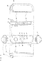
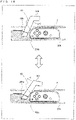
- FIG. 8 is a diagram showing an example of the state where a user performs a game operation by attaching the accessory 200.
- the main body apparatus 2, the left controller 3, and the right controller 4 can be attached to the accessory 200.
- a process corresponding to the content of an operation on the accessory 200 is executed.
- the accessory 200 does not need to have an electrical structure such as an electronic circuit for detecting the content of an operation performed by the user and transmitting the detection result to the main body apparatus 2.
- the accessory 200 it is possible to simplify the configuration of the accessory 200, which is an example of the extension operation device.
- the user uses the accessory 200 in the state where the extremity of a supporting portion (a supporting portion 201 described later) provided between both holding portions abuts a front portion of the torso of the user's body.
- the user performs an operation using the accessory 200 by tilting the entirety of the accessory 200, twisting one of the holding portions (e.g., the right controller supporting portion 204 held by the right hand of the user), moving both holding portions as if operating a steering wheel, or operating operation sections (a blinker operation section 205, a brake operation section 206, and a starter operation section 207 described later) provided in the accessory 200.
- the accessory 200 can simulate a motorbike, and the user can perform the operation of performing the simulated driving of the motorbike using the accessory 200.
- the up, down, left, and right directions of the accessory 200 are defined as directions viewed from the user based on the state where the user uses the accessory 200.
- the direction in which a holding portion (the left controller supporting portion 203 described later) capable of being held by the left hand is provided is the left direction of the accessory 200.
- the direction in which a holding portion (the right controller supporting portion 204 described later) capable of being held by the right hand is provided is the right direction of the accessory 200.
- the main body apparatus 2 To an upper surface of a main body portion (a main body portion 202 described later) of the accessory 200, the main body apparatus 2 is attached. Then, in accordance with an operation using the accessory 200 as described above, a player object placed in a virtual space performs an action, and an image of the virtual space reflecting the action of the player object is displayed on the display 12 of the main body apparatus 2.
- an operation button (the first L-button 38 or the ZL-button 39) of the left controller 3 attached to the inside of the left controller supporting portion 203, or an operation button (the first R-button 60 or the ZR-button 61) of the right controller 4 attached to the inside of the right controller supporting portion 204 is pressed.
- Such a pressing operation on the operation button is detected, whereby it is estimated that the user operating the accessory 200 operates an operation section.
- the player object also performs an action in the virtual space.
- each of the left controller 3 and the right controller 4 attached to the accessory 200 includes the inertial sensors (the acceleration sensor and the angular velocity sensor).
- the inertial sensors the acceleration sensor and the angular velocity sensor.
- the right controller 4 attached to the inside of the right controller supporting portion 204 roll-rotates. Such a motion of the right controller 4 is detected, whereby it is estimated that the user operating the accessory 200 performs an operation as if twisting the accelerator. Then, the player object also moves in the virtual space at a velocity corresponding to an estimated accelerator position.
- the left controller 3 attached to the inside of the left controller supporting portion 203 (see FIGS. 9 to 11 ) roll-rotates. Such a motion of the roll rotation of the left controller 3 is detected, whereby it is estimated that the user operating the accessory 200 performs an operation as if performing a wheelie. Then, the player object also performs a wheelie action in the virtual space in accordance with an estimated change in the orientation.
- the left controller 3 attached to the inside of the left controller supporting portion 203 yaw-rotates.
- Such a motion of the yaw rotation of the left controller 3 is detected, whereby it is estimated that the user operating the accessory 200 performs the operation of turning the steering wheel.
- the player object also changes its moving direction in the virtual space in accordance with an estimated change in the direction.
- the left controller 3 attached to the inside of the left controller supporting portion 203 pitch-rotates.
- Such a motion of the pitch rotation of the left controller 3 is detected, whereby it is estimated that the user operating the accessory 200 performs the operation of falling over to the left and right. Then, the player object also tilts and/or changes its moving direction in the virtual space in accordance with an estimated tilting change.
- another change may occur in accordance with the state (e.g., the moving velocity or the accelerator position) of the player object moving in the virtual space.
- the wheelie action may be able to be performed only while the player object is moving at a predetermined moving velocity or more in the virtual space (e.g., in the state where the accelerator position is equal to or greater than a predetermined value).
- the direction in which the player object is directed may be simply changed to the up direction in the virtual space without performing the wheelie action.
- the motion of the roll rotation of the left controller 3 is detected, whereby it is estimated that the user operating the accessory 200 performs an operation as if performing a wheelie.
- another motion may be detected, thereby detecting the wheelie operation.
- the motion of the main body apparatus 2, attached to the accessory 200, rotating in the pitch direction (the direction in which the main body apparatus 2 rotates about an x-axis direction shown in FIG. 1 ) may be detected, thereby estimating that the user operating the accessory 200 performs an operation as if performing a wheelie.
- the rotation in the pitch direction of the main body apparatus 2 may be detected using angular velocities detected by the angular velocity sensor 90, which is provided in the main body apparatus 2.
- the roll rotation of the right controller 4 attached to the accessory 200 may be detected, thereby estimating that the user operating the accessory 200 performs an operation as if performing a wheelie.
- the wheelie operation can be detected based on the roll rotation of the right controller 4.
- the wheelie operation, the operation of turning the steering wheel, and the operation of tilting the entirety of the accessory 200 to the left and right are performed in addition to the accelerator operation.
- at least one of the wheelie operation, the operation of turning the steering wheel, and the operation of tilting the entirety of the accessory 200 to the left and right may be implemented in addition to the accelerator operation.
- the player object that performs an action in accordance with an operation using the accessory 200 is displayed on the display 12 of the main body apparatus 2.
- the user operating the accessory 200 enjoys a game by viewing the display 12 of the main body apparatus 2, which is provided on an upper surface of the accessory 200 (the upper surface of the main body portion 202).
- the viewpoint from which the player object on the display 12 is displayed may be placed at any position in the virtual space.
- a virtual space image obtained by viewing the player object from behind the player object may be displayed on the above display device.
- a virtual space image from a first-person viewpoint of the player object may be displayed on the above display device.
- a virtual space image obtained by viewing the player object from the front of the player object may be displayed on the above display device.
- a part or the action direction of the player object performing an action in response to an operation using the accessory 200 is set in accordance with the viewpoint and the direction of the line of sight, whereby it is possible to provide realistic game play. Further, vibrations corresponding to the game situation are imparted to the left controller 3 and/or the right controller 4.
- the vibrations of the left controller 3 and/or the right controller 4 are transmitted via the left controller supporting portion 203 and/or the right controller supporting portion 204.
- the vibrations of the left controller 3 and/or the right controller 4 are transmitted via the left controller supporting portion 203 and/or the right controller supporting portion 204.
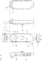
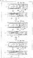
- FIG. 9 is a perspective view showing an example of the external appearance of the accessory 200.
- FIG. 10 is six orthogonal views showing an example of the external appearance of the accessory 200.
- FIG. 11 is a diagram showing an example of the state where the main body apparatus 2, the left controller 3, and the right controller 4 are attached to the accessory 200.
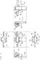
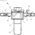
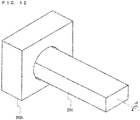
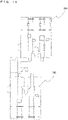
- FIG. 12 is a diagram showing an example of an accelerator mechanism of the accessory 200.
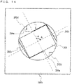
- FIG. 13 is a diagram showing an example of a first state of the accelerator mechanism of the accessory 200.
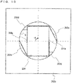
- FIG. 14 is a diagram showing an example of a second state of the accelerator mechanism of the accessory 200.
- FIG. 15 is a diagram showing an example of a third state of the accelerator mechanism of the accessory 200.
- FIG. 16 is a diagram showing an example of a brake mechanism of the accessory 200.
- FIG. 17 is a diagram showing an example of a blinker mechanism of the accessory 200.
- the accessory 200 includes a supporting portion 201, a main body portion 202, a left controller supporting portion 203, and a right controller supporting portion 204.
- the entirety of the accessory 200 has a shape representing a front portion of a motorbike including a steering wheel.
- the user can perform the operation of performing the simulated driving of the motorbike using the accessory 200 by causing the back end of the supporting portion 201 to abut a front portion of the torso of the user while holding the left controller supporting portion 203 and the right controller supporting portion 204 on the left and right with their left and right hands.
- the main body portion 202 is attached to an upper surface of the supporting portion 201 so as to rotate in a B direction shown in the figures.
- the left controller supporting portion 203 is provided on a left side surface of the main body portion 202 by inserting the left controller supporting portion 203
- the right controller supporting portion 204 is provided on a right side surface of the main body portion 202 by inserting the right controller supporting portion 204.
- the supporting portion 201 is a plate-like member of which the front-back direction is its longitudinal direction. On a front upper surface of the supporting portion 201, a shaft portion (not shown) to be inserted into the main body portion 202 is provided standing in the up direction. To a back end portion of the supporting portion 201, an extension portion 201a for adjusting the length in the longitudinal direction of the supporting portion 201 can be attached. When the extension portion 201a is attached to the back end portion of the supporting portion 201, the length in the longitudinal direction becomes long. Thus, the distances from the back end of the accessory 200 to the main body portion 202, the left controller supporting portion 203, and the right controller supporting portion 204 become long. Thus, the user detaches and attaches the extension portion 201a from and to the supporting portion 201 and thereby can adjust the length in the front-back direction of the accessory 200 in accordance with the build of the user themselves.
- the main body portion 202 is rotationally provided in the shaft portion provided in the supporting portion 201 and is supported so as to rotate in the B direction shown in the figures on the front upper surface of the supporting portion 201.
- a main body apparatus fixing portion 202a is formed, to which the main body apparatus 2 is attachably and detachably fixed.
- the main body apparatus fixing portion 202a can fix the main body apparatus 2 to the upper surface of the main body portion 202 by clamping up, down, left, and right end portions of the main body apparatus 2.
- the main body apparatus fixing portion 202a fixes the main body apparatus 2 such that the display 12 of the main body apparatus 2 is an upper surface, whereby the user can view an image displayed on the display 12 while operating the accessory 200.
- the left controller supporting portion 203 is laterally provided on and fixed to the left side surface such that the longitudinal direction of the left controller supporting portion 203 is the left direction.
- the right controller supporting portion 204 is laterally provided on the right side surface such that the longitudinal direction of the right controller supporting portion 204 is the right direction. That is, the left controller supporting portion 203 is provided on one side of the main body portion 202, and the right controller supporting portion 204 is provided on the other side of the main body portion 202.
- the left controller supporting portion 203 and the right controller supporting portion 204 move integrally with the motion of the main body portion 202.
- the left controller supporting portion 203 and the right controller supporting portion 204 also rotate integrally in the B direction shown in the figures.
- the left controller supporting portion 203 and the right controller supporting portion 204 are provided in the main body portion 202 such that the longitudinal direction of the left controller supporting portion 203 and the longitudinal direction of the right controller supporting portion 204 are on approximately the same straight line or are left and right directions approximately parallel to each other.
- the right controller supporting portion 204 is provided on the right side surface of the main body portion 202 by inserting the right controller supporting portion 204 so as to rotate about a long axis, which is the longitudinal direction (an A direction shown in the figures).
- the right controller supporting portion 204 can roll-rotate in the A direction shown in the figures relative to the left controller supporting portion 203 or the main body portion 202.
- the left controller 3 is detachably attached to the inside of the left controller supporting portion 203.
- the length in the up-down direction of an inner space of the left controller supporting portion 203 is almost the same as the maximum thickness (the maximum length in a z-axis direction shown in FIG. 1 ) of the left controller 3, and the length in the left-right direction of the left controller supporting portion 203 is almost the same as the maximum width in the left-right direction (the maximum length in the x-axis direction shown in FIG. 1 ) of the left controller 3.
- the left controller 3 can be inserted into the inner space of the left controller supporting portion 203 and fixed such that the longitudinal direction of the left controller supporting portion 203 coincides with the longitudinal direction of the left controller 3. For example, as shown in FIG.
- the left controller 3 can be attached to the left controller supporting portion 203 such that a main surface (a surface formed further in a negative z-axis direction in FIG. 4 ) of the left controller 3 is in the up direction, and an upper side surface (a surface further in a positive y-axis direction in FIG. 4 ) of the left controller 3 is in the right direction, which is on the main body portion 202 side.
- a main surface a surface formed further in a negative z-axis direction in FIG. 4
- an upper side surface a surface further in a positive y-axis direction in FIG. 4
- the left controller 3 attached to the left controller supporting portion 203 is attached to the accessory 200 such that the positive x-axis direction of the left controller 3 is the front direction of the accessory 200, the positive y-axis direction of the left controller 3 is the right direction of the accessory 200, and the positive z-axis direction of the left controller 3 is the down direction of the accessory 200. Then, when a front portion of the accessory 200 is brought up, or the front portion of the accessory 200 is brought down, the left controller 3 attached to the left controller supporting portion 203 rotates in the roll direction. When the main body portion 202 is caused to rotate in the B direction shown in the figures as if turning a steering wheel, the left controller 3 attached to the left controller supporting portion 203 rotates in the yaw direction.
- the left controller 3 attached to the left controller supporting portion 203 rotates in the pitch direction. It should be noted that a part of the left controller 3 attached to the left controller supporting portion 203 may be exposed to outside. For example, the analog stick 32 and the like may be exposed on an upper surface of the left controller supporting portion 203.
- the left controller supporting portion 203 includes a blinker operation section 205.
- the blinker operation section 205 is provided on the main body portion 202 side on a back side surface (a side surface on the side where the user operates the accessory 200) of the left controller supporting portion 203 and can be operated by the left thumb and the like of the user holding the left controller supporting portion 203.
- the blinker operation section 205 includes an operation piece for moving to the left and right in accordance with a user operation. Then, as will be apparent later, in the blinker operation section 205, it is possible to selectively perform a pressing operation on one of the first L-button 38 and the ZL-button 39 of the left controller 3 by moving the operation piece to the left and right.
- the right controller 4 is detachably attached to the inside of the right controller supporting portion 204.
- the length in the up-down direction of an inner space of the right controller supporting portion 204 is almost the same as the maximum thickness (the maximum length in the z-axis direction shown in FIG. 1 ) of the right controller 4, and the length in the left-right direction of the right controller supporting portion 204 is almost the same as the maximum width in the left-right direction (the maximum length in the x-axis direction shown in FIG. 1 ) of the right controller 4.
- the right controller 4 can be inserted into the inner space of the right controller supporting portion 204 and fixed such that the longitudinal direction of the right controller supporting portion 204 coincides with the longitudinal direction of the right controller 4. For example, as shown in FIG.
- the right controller 4 can be attached to the right controller supporting portion 204 such that a main surface (a surface formed further in a negative z-axis direction in FIG. 5 ) of the right controller 4 is in the up direction, and an upper side surface (a surface further in a positive y-axis direction in FIG. 5 ) of the right controller 4 is in the left direction, which is on the main body portion 202 side.
- a main surface a surface formed further in a negative z-axis direction in FIG. 5
- an upper side surface a surface further in a positive y-axis direction in FIG. 5
- the right controller 4 attached to the right controller supporting portion 204 is attached to the accessory 200 such that the positive x-axis direction of the right controller 4 is the back direction of the accessory 200, the positive y-axis direction of the right controller 4 is the left direction of the accessory 200, and the positive z-axis direction of the right controller 4 is the down direction of the accessory 200. Then, when the right controller supporting portion 204 is operated so as to rotate in the A direction shown in the figures, the right controller 4 attached to the right controller supporting portion 204 rotates in the roll direction. Further, when the front portion of the accessory 200 is brought up, or the front portion of the accessory 200 is brought down, the right controller 4 attached to the right controller supporting portion 204 rotates in the roll direction.
- the right controller 4 attached to the right controller supporting portion 204 rotates in the yaw direction and/or the pitch direction in accordance with the rotational angle of the right controller supporting portion 204 in the A direction shown in the figures.
- the entirety of the accessory 200 is tilted to the left and right, the right controller 4 attached to the right controller supporting portion 204 rotates in the yaw direction and/or the pitch direction in accordance with the rotational angle of the right controller supporting portion 204 in the A direction shown in the figures.
- a part of the right controller 4 attached to the right controller supporting portion 204 may be exposed to outside.
- the analog stick 52, the "+" button 57, and the like may be exposed on an upper surface of the right controller supporting portion 204.
- the right controller supporting portion 204 includes a brake operation section 206 and a starter operation section 207.
- the brake operation section 206 is provided on the main body portion 202 side on a front side surface (a surface on the opposite side opposed to a side surface on the side where the user operates the accessory 200) of the right controller supporting portion 204 and can be operated by the right index finger or the like of the user holding the right controller supporting portion 204.
- the brake operation section 206 includes an operation piece for moving to the near side in accordance with a user operation. Then, as will be apparent later, in the brake operation section 206, it is possible to perform a pressing operation on the first R-button 60 of the right controller 4 by moving the operation piece to the near side.
- the starter operation section 207 is provided on the main body portion 202 side of a back side surface (the side surface on the side where the user operates the accessory 200) of the right controller supporting portion 204 and can be operated by the right thumb and the like of the user holding the right controller supporting portion 204.
- the starter operation section 207 includes an operation piece capable of being pressed (subjected to a push-in operation) in accordance with a user operation. Then, in the starter operation section 207, it is possible to perform a pressing operation on the ZR-button 61 of the right controller 4 by pressing (pushing in) the operation piece.
- the right controller supporting portion 204 is provided by inserting the right controller supporting portion 204 so as to rotate in the A direction shown in the figures relative to the main body portion 202.
- a bearing portion 202b for supporting the right controller supporting portion 204 so as to rotate is provided within the main body portion 202.
- the right controller supporting portion 204 can rotate in the A direction shown in the figures along a cylindrical inner surface S of the bearing portion 202b.
- the right controller supporting portion 204 is biased in an -A direction shown in the figures (e.g., a clockwise direction when the main body portion 202 is viewed from a right end portion of the right controller supporting portion 204) about the axis of the bearing portion 202b.
- the right controller supporting portion 204 is biased in the -A direction shown in the figures by tension stress caused by elastic members 202c, which are provided in a stretched manner between the right controller supporting portion 204 and the bearing portion 202b.
- elastic members 202c e.g., rubber bands
- one ends of the plurality of elastic members 202c are fixed to the cylindrical inner surface S of the bearing portion 202b, and the other ends of the plurality of elastic members 202c are hooked to the elastic member hook portions 204a such that the right controller supporting portion 204 is biased in the -A direction shown in the figures.
- rotation restriction portions 202d are provided, which stop the rotational action of the right controller supporting portion 204.
- the rotation restriction portions 202d are formed of protruding portions protruding from the cylindrical inner surface S of the bearing portion 202b. Consequently, when the side surfaces of the right controller supporting portion 204 rotation along the cylindrical inner surface S of the bearing portion 202b abut the rotation restriction portions 202d, the rotation of the right controller supporting portion 204 stops at the position of the abutment.
- the rotation stops at the position where the side surfaces of the right controller supporting portion 204 and the rotation restriction portions 202d abut each other.
- the position of the stop is an initial position of the right controller supporting portion 204 in the rotational action (the state in FIG. 13 ).
- the rotation restriction portions 202d are provided in two places on the cylindrical inner surface S of the bearing portion 202b, and the two rotation restriction portions 202d simultaneously abut the side surfaces (more specifically, two side surfaces opposed to each other) of the right controller supporting portion 204 at the initial position.
- a plurality of rotation restriction portions 202d are thus provided, whereby it is possible to securely stop the rotation of the right controller supporting portion 204 at the initial position.
- the initial position of the right controller supporting portion 204 may be at any angle.
- the right controller supporting portion 204 may be tilted by 10 degrees in an elevation direction or a depression direction from the horizontal direction shown in FIG. 13 , or the initial angle may be any angle.
- the user of the accessory 200 can perform the operation of rotation, in a +A direction shown in the figures, the right controller supporting portion 204 stopping its rotational action at the initial position. Specifically, the user performs the operation of twisting the right controller supporting portion 204 that the user holds with their right hand, in the +A direction shown in the figures with a greater force than the biasing forces of the elastic members 202c, whereby the right controller supporting portion 204 rotates in the +A direction shown in the figures along the cylindrical inner surface S of the bearing portion 202b. At this time, the user can further rotate the right controller supporting portion 204 in the +A direction shown in the figures.
- the right controller supporting portion 204 rotates in the -A direction shown in the figures by the biasing forces of the elastic members 202c and stops at the initial position. That is, the operation of rotation the right controller supporting portion 204 simulates an accelerator operation on a motorbike. Thus, it is possible to cause the right controller supporting portion 204 to function as the accelerator mechanism of the accessory 200. Then, the right controller 4 attached to the inside of the right controller supporting portion 204 rotates in the roll direction in accordance with the accelerator operation using the right controller supporting portion 204. Thus, it is possible to calculate the accelerator operation (the accelerator position) of the user by detecting this rotation.
- the difference between the orientation of the left controller 3 and the orientation of the right controller 4 is calculated, and using a value indicating the calculated difference, the accelerator operation (the accelerator position) of the user is calculated.
- the left controller supporting portion 203 for fixing the left controller 3 cannot rotate in the A direction shown in the figures relative to the main body portion 202 and is fixed to the main body portion 202. That is, the difference between the orientation in the roll direction of the left controller 3 and the orientation in the roll direction of the right controller 4 is considered to be caused by the accelerator operation.
- the accelerator operation (the accelerator position) of the user is calculated using the difference value between the orientation of the left controller 3 and the orientation of the right controller 4.
- the side surfaces of the right controller supporting portion 204 rotation along the cylindrical inner surface S of the bearing portion 202b abut the rotation restriction portions 202d (the state in FIG. 15 ). Specifically, the side surface of the right controller supporting portion 204 abutting an abutment surface on one side of the rotation restriction portions 202d at the initial position abuts an abutment surface on the other side of the rotation restriction portions 202d, thereby stopping the rotation of the right controller supporting portion 204.
- the rotation restriction portions 202d which function as a stopper for stopping the right controller supporting portion 204 at the initial position, also function as a stopper for stopping the right controller supporting portion 204 at a maximum rotational angle. It should be noted that in the examples shown in FIGS. 13 to 15 , an example is used where the maximum rotational angle allowing the right controller supporting portion 204 to rotate is 90 degrees. Alternatively, the maximum rotational angle can be set to various angles depending on the shapes and the number of rotation restriction portions 202d, or the shape of the right controller supporting portion 204.
- the brake operation section 206 is provided in the right controller supporting portion 204.
- the brake operation section 206 penetrates to the inside of the right controller supporting portion 204, and a part of the brake operation section 206 protrudes to the outside of the right controller supporting portion 204, as an operation piece capable of being operated by the user. Then, the brake operation section 206 is provided on the front side surface (the surface on the opposite side opposed to the side surface on the side where the user operates the accessory 200) of the right controller supporting portion 204. Thus, it is possible to perform the operation of moving the operation piece of the brake operation section 206 to the near side (in a +C direction shown in the figures) by pulling the operation piece close to the front side surface.
- the brake operation section 206 is biased in a direction (a -C direction shown in the figures) opposite to the direction of the above operation.
- the brake operation section 206 is biased in the -C direction shown in the figures by tension stress caused by an elastic member 206a, which is provided in a stretched manner between the brake operation section 206 and a member within the right controller supporting portion 204.
- an elastic member hook portion 206b is formed, to which the elastic member 206a (e.g., a rubber band) is hooked.
- one end of the elastic member 206a is fixed to the member within the right controller supporting portion 204, and the other end of the elastic member 206a is hooked to the elastic member hook portion 206b, whereby the brake operation section 206 is biased in the -C direction shown in the figures.
- the brake operation section 206 is biased by the elastic member 206a such as a rubber band.
- the elastic member 206a may not be included.
- the brake operation section 206 may be biased in the -C direction shown in the figures, using the restoring force of the brake operation section 206 or the right controller supporting portion 204 itself.
- the user of the accessory 200 can perform the operation of tilting, in the +C direction shown in the figures, the operation piece of the brake operation section 206 biased in the -C direction shown in the figures. Specifically, the user performs the operation of tilting the brake operation section 206 in the +C direction shown in the figures with a greater force than the biasing force of the elastic member 206a, whereby the brake operation section 206 tilts toward the right controller 4 attached to the inside of the right controller supporting portion 204. Then, a part of the brake operation section 206 tilting in the +C direction shown in the figures abuts the first R-button 60 of the right controller 4.
- the blinker operation section 205 is provided in the left controller supporting portion 203.
- the blinker operation section 205 penetrates to the inside of the left controller supporting portion 203, and a part of the blinker operation section 205 protrudes to the outside of the left controller supporting portion 203, as an operation piece capable of being operated by the user. Then, the blinker operation section 205 is provided on the back side surface (the side surface on the side where the user operates the accessory 200) of the left controller supporting portion 203. Thus, it is possible to perform the operation of moving the operation piece of the blinker operation section 205 to the left (in a +D direction shown in the figures) or the right (in a -D direction shown in the figures).
- the blinker operation section 205 tilts (rotates) to the right about a predetermined fixing portion (a shaded area having a band shape shown in FIG. 17 ). Consequently, a portion of the blinker operation section 205 on the side closer to the operation piece with respect to the fixing portion moves to the left side, and a portion of the blinker operation section 205 on the side closer to a front portion with respect to the fixing portion is moves to the right side.
- the blinker operation section 205 thus moves, whereby the portion of the blinker operation section 205 on the side closer to the operation piece moves toward the left controller 3 attached to the inside of the left controller supporting portion 203, and the portion of the blinker operation section 205 on the side closer to the front portion moves in a direction away from the left controller 3 attached to the inside of the left controller supporting portion 203. Then, a part of the blinker operation section 205 moving in accordance with the operation of moving the operation piece in the +D direction shown in the figures abuts the ZL-button 39 of the left controller 3. Thus, it is possible to perform a pressing operation on the ZL-button 39 by the operation of moving the blinker operation section 205 in the +D direction shown in the figures.
- the blinker operation section 205 tilts (rotates) to the left about the predetermined fixing portion (the shaded area having a band shape shown in FIG. 17 ). Consequently, the portion of the blinker operation section 205 on the side closer to the operation piece with respect to the fixing portion moves to the right side, and the portion of the blinker operation section 205 on the side closer to the front portion with respect to the fixing portion moves to the left side.
- the blinker operation section 205 thus moves, whereby the portion of the blinker operation section 205 on the side closer to the front portion moves toward the left controller 3 attached to the inside of the left controller supporting portion 203, and the portion of the blinker operation section 205 on the side closer to the operation piece moves in a direction away from the left controller 3 attached to the inside of the left controller supporting portion 203. Then, a part of the blinker operation section 205 moving in accordance with the operation of moving the operation piece in the -D direction shown in the figures abuts the first L-button 38 of the left controller 3. Thus, it is possible to perform a pressing operation on the first L-button 38 by the operation of moving the blinker operation section 205 in the -D direction shown in the figures.
- the operation of moving the blinker operation section 205 simulates a blinker operation on a motorbike.
- the pressing operation on the ZL-button 39 of the left controller 3 is detected, whereby it is possible to detect the blinker operation of the user indicating the left direction.
- the pressing operation on the first L-button 38 of the left controller 3 is detected, whereby it is possible to detect the blinker operation of the user indicating the right direction.
- FIG. 18 is a diagram showing examples of parts of cardboard members for assembling the main body portion 202.
- FIG. 19 is a diagram showing examples of parts of cardboard members for assembling the left controller supporting portion 203 and the right controller supporting portion 204. It should be noted that in FIGS. 18 and 19 , a solid line indicates a line for cutting off each cardboard member, and a dashed-dotted line indicates a line for mountain-folding or valley-folding each cardboard member.
- components of the accessory 200 are formed by folding the cardboard members.
- the cardboard members may be a single plate member having a stack structure or a plurality of plate members bonded together.
- the cardboard members may each be a so-called corrugated cardboard member, which is formed by bonding a plate-like paper sheet to one surface or both of two surfaces of a corrugated plate-like paper sheet.
- the main body portion 202 is formed by folding a single cardboard member into a three-dimensional shape. Then, the main body portion 202 is assembled by incorporating components included in the main body portion 202, such as inserting a member to be a side wall of the main body apparatus fixing portion 202a into the upper surface of the main body portion 202 and fixing the member. Further, main body portions of the left controller supporting portion 203 and the right controller supporting portion 204 are assembled by folding the left controller supporting portion 203 and the right controller supporting portion 204 into angular tubes. Then, the left controller supporting portion 203 and the right controller supporting portion 204 are assembled by incorporating components included in the left controller supporting portion 203 and the right controller supporting portion 204 into the main body portions.
- the main body portion 202 is assembled by folding a plate member in which a plurality of pass-through holes through which members to be side walls of the main body apparatus fixing portion 202a pass, a bearing hole to be a part of the bearing portion 202b, and the like are formed.
- the plate member is formed of a cardboard member, and the cardboard member is folded into a three-dimensional shape for forming the main body portion 202, thereby assembling the main body portion 202.
- side wall portions of the main body apparatus fixing portion 202a are assembled by folding a plate member in which insertion tabs to be inserted into the pass-through holes of the main body portion 202 and the like are formed.
- the left controller supporting portion 203 is assembled by folding a plate member in which a plurality of pass-through holes through which components included in the left controller supporting portion 203 pass, inner walls for fixing the left controller 3 to the inside of the left controller supporting portion 203, a cover of an end portion to be closed after the left controller 3 is attached to the inside of the left controller supporting portion 203, and the like are formed, into an angular tube.
- the right controller supporting portion 204 is assembled by folding a plate member in which a plurality of pass-through holes through which components included in the right controller supporting portion 204 pass, inner walls for fixing the right controller 4 to the inside of the right controller supporting portion 204, a cover of an end portion to be closed after the right controller 4 is attached to the inside of the right controller supporting portion 204, and a shaft portion for passing through the bearing portion 202b, and the like are formed, into an angular tube.
- the accessory 200 is assembled by combining the main body portion 202, the left controller supporting portion 203, the right controller supporting portion 204, and the like.
- the accessory 200 is formed by combining components assembled by folding cardboard members.
- the accessory 200 does not need to have an electrical structure such as an electronic circuit for detecting the content of an operation performed by the user and transmitting the detection result to the main body apparatus 2, and therefore can be achieved as the above product to be assembled by the user.
- the surfaces may be bonded together by any method.
- the sides of the surfaces may be bonded together by an adhesive tape.
- An insertion tab may be formed on one of the sides, and an insertion hole may be formed in the other side, so that the insertion tab may be inserted into the insertion hole.
- the sides of the surfaces may be bonded together by an adhesive agent.
- the components of the accessory 200 are each formed of a cardboard member.
- at least a part of these components may be a thin paper sheet or another type of plate member.
- at least a part of these components may be assembled by folding a resinous, wooden or metallic thin or thick plate member or may be strip-like fiber members.
- the elastic members 202c and the elastic member 206a may each be formed of a member made of a metal material or a non-metal material such as rubber, resin, or ceramics. A part of these components may be combined with a component of a different material. For example, a hole (e.g., a bearing hole) through which another member passes can be scraped by the movement of the member. Thus, a ring member or a sheet member made of resin or the like can be inserted into a portion that comes into contact with another member in the hole. At least parts of the components may be provided in advance as a polyhedron component. Further, at least parts of the components may be formed as a polyhedron component in advance.
- FIG. 20 is a diagram showing an example of a data area set in the DRAM 85 of the main body apparatus 2 according to the exemplary embodiment. It should be noted that in the DRAM 85, in addition to data shown in FIG. 20 , data used for other processes is also stored, but is not described in detail here.
- various programs Pa which are executed by the main body apparatus 2, are stored.
- a communication program for wirelessly communicating with the left controller 3 and the right controller 4 an application program for performing information processing (e.g., game processing) based on data acquired from the left controller 3 and/or the right controller 4, a vibration control program for vibrating the left controller 3 and/or the right controller 4, and the like are stored.
- the various programs Pa may be stored in advance in the flash memory 84, or may be acquired from a storage medium attachable to and detachable from the game system 1 (e.g., a storage medium attached to the slot 23) and stored in the DRAM 85, or may be acquired from another apparatus via a network such as the Internet and stored in the DRAM 85.
- the processor 81 executes the various programs Pa stored in the DRAM 85.
- a data storage area of the DRAM 85 various data used for processes such as a communication process, information processing, and the like executed by the main body apparatus 2 is stored.
- operation data Da, orientation data Db, difference value data Dc, object action data Dd, moving velocity/moving direction data De, vibration data Df, image data Dg, and the like are stored.
- the operation data Da is operation data appropriately acquired from each of the left controller 3 and/or the right controller 4.
- the operation data transmitted from each of the left controller 3 and/or the right controller 4 includes information regarding an input (specifically, information regarding an operation or the detection result of the sensor) from each of the input sections (specifically, each button, each analog stick, or each sensor).
- operation data is transmitted from each of the left controller 3 and/or the right controller 4 through wireless communication in a predetermined cycle, and the operation data Da is appropriately updated using the received operation data.
- the update cycle of the operation data Dc may be such that the operation data Da is updated every frame, which is the cycle of the processing described later executed by the game system 1, or is updated every cycle in which the above operation data is output through the wireless communication.
- the operation data Da includes button operation data Da1, angular velocity data Da2, acceleration data Da3, and the like.
- the button operation data Da1 is data indicating information regarding an input from each button or each analog stick of the left controller 3 and the right controller 4.
- the angular velocity data Da2 is data indicating information regarding angular velocities generated in the left controller 3 and detected by the angular velocity sensor 105 of the left controller 3, and information regarding angular velocities generated in the right controller 4 and detected by the angular velocity sensor 115 of the right controller 4.
- the angular velocity data Da2 includes data indicating angular velocities generated about the xyz axes in each of the left controller 3 and the right controller 4.
- the acceleration data Da3 is data indicating information regarding accelerations generated in the left controller 3 and detected by the acceleration sensor 104 of the left controller 3, and information regarding accelerations generated in the right controller 4 and detected by the acceleration sensor 114 of the right controller 4.
- the acceleration data Da3 includes data indicating accelerations generated in the xyz axis directions in each of the left controller 3 and the right controller 4.
- the orientation data Db is data indicating each of the orientations of the left controller 3 and the right controller 4 with respect to the direction of a gravitational acceleration in real space.
- the orientation data Db includes data indicating the direction of a gravitational acceleration acting on each of the left controller 3 and the right controller 4, data indicating xyz axis directions relative to the direction of the gravitational acceleration, and the like.
- the difference value data Dc is data indicating a difference value indicating the difference (e.g., the difference in angle) between the orientations of the left controller 3 and the right controller 4 in the roll direction.
- the object action data Dd is data regarding the action of a player object placed in a virtual world.
- the moving velocity/moving direction data De is data indicating the moving velocity or the moving direction of the player object placed in the virtual world.
- the vibration data Df is data indicating vibrations for vibrating the left controller 3 and the right controller 4.
- the image data Dg is data for displaying images (e.g., an image of the player object, an image of another object, a background image, and the like) on a display device (e.g., the display 12 of the main body apparatus 2) when a game is performed.
- images e.g., an image of the player object, an image of another object, a background image, and the like
- a display device e.g., the display 12 of the main body apparatus 2
- FIG. 21 is a flow chart showing an example of the information processing executed by the main body apparatus 2.
- a series of processes shown in FIG. 21 is performed by the processor 81 executing the communication program and a predetermined application program (a game program) included in the various programs Pa. Further, the information processing shown in FIG. 21 is started at any timing.
- the processes of all of the steps in the flow chart shown in FIG. 21 are merely illustrative. Thus, the processing order of the steps may be changed, or another process may be performed in addition to (or instead of) the processes of all of the steps, so long as similar results are obtained. Further, in the exemplary embodiment, descriptions are given on the assumption that the processor 81 performs the processes of all of the steps in the flow charts. Alternatively, a processor or a dedicated circuit other than the processor 81 may perform the processes of some of the steps in the flow charts. Yet alternatively, part of the processing performed by the main body apparatus 2 may be executed by another information processing apparatus capable of communicating with the main body apparatus 2 (e.g., a server capable of communicating with the main body apparatus 2 via a network). That is, all the processes shown in FIG. 21 may be executed by the cooperation of a plurality of information processing apparatuses including the main body apparatus 2.
- a server capable of communicating with the main body apparatus 2 via a network
- the processor 81 performs initialization in the game processing (step S161), and the processing proceeds to the next step. For example, in the initialization, the processor 81 initializes parameters for performing the processing described below. Further, in the initialization, the processor 81 sets the type and identification information of the accessory 200 (the extension operation device) to which the main body apparatus 2, the left controller 3, and the right controller 4 are attached, where necessary. For example, the type of the accessory 200 may be initialized by the user performing the operation of selecting the type of the accessory 200, using the main body apparatus 2, the left controller 3, or the right controller 4.
- the processor 81 acquires operation data from each of the left controller 3 and the right controller 4 and updates the operation data Da (step S162), and the processing proceeds to the next step. For example, in accordance with the operation data acquired from each of the left controller 3 and the right controller 4, the processor 81 updates the button operation data Da1, the angular velocity data Da2, and the acceleration data Da3.
- the processor 81 performs the process of setting an object action (step S163), and the processing proceeds to the next step. For example, using the operation data acquired in the above step S162, the processor 81 determines whether or not the operation buttons provided in the left controller 3 and the right controller 4 (specifically, the first L-button 38 and the ZL-button 39 of the left controller 3 and the first R-button 60 and the ZR-button 61 of the right controller 4) are subjected to pressing operations.
- the processor 81 sets an action in which a player object indicates the left direction in a virtual space (e.g., the action of blinking a left blinker of a motorbike that the player object rides), thereby updating the object action data Dd. Further, when the ZL-button 39 is subjected to a pressing operation, the processor 81 sets an action in which the player object indicates the right direction in the virtual space (e.g., the action of blinking a right blinker of the motorbike that the player object rides), thereby updating the object action data Dd.
- the processor 81 sets an action in which the moving velocity of the player object decelerates in the virtual space (e.g., the moving velocity of the motorbike that the player object rides decelerates by a predetermined negative acceleration), thereby updating the object action data Dd.
- the processor 81 sets an action in which the engine or the motor of the vehicle that the player object rides is started in the virtual space, thereby updating the object action data Dd.
- the processor 81 calculates the orientations of the left controller 3 and the right controller 4 (step S164), and the processing proceeds to the next step. For example, the processor 81 acquires data indicating accelerations generated in the left controller 3 from the acceleration data Da3, calculates the direction of a gravitational acceleration acting on the left controller 3, and updates the orientation data Db of the left controller 3 using data indicating the direction.
- a method for extracting a gravitational acceleration any method may be used. For example, an acceleration component generated on average in the left controller 3 may be calculated and extracted as a gravitational acceleration.
- the processor 81 acquires data indicating angular velocities generated in the left controller 3 from the angular velocity data Da2, calculates angular velocities about the xyz axes of the left controller 3, and calculates the xyz axis directions of the left controller 3 with respect to the direction of the gravitational acceleration using data indicating the angular velocities, thereby updating the orientation data Db of the left controller 3. Further, the processor 81 acquires data indicating accelerations generated in the right controller 4 from the acceleration data Da3, calculates the direction of a gravitational acceleration acting on the right controller 4, and updates the orientation data Db of the right controller 4 using data indicating the direction.
- the processor 81 acquires data indicating angular velocities generated in the right controller 4 from the angular velocity data Da2, calculates the angular velocities about the xyz axes of the right controller 4, and calculates the xyz axis directions of the right controller 4 with respect to the direction of the gravitational acceleration using data indicating the angular velocities, thereby updating the orientation data Db of the right controller 4.
- the orientations of the left controller 3 and the right controller 4 may be updated in accordance with only the angular velocities about the xyz axes.
- the xyz axis directions relative to the direction of the gravitational acceleration may be calculated every predetermined cycle, and the orientations of the left controller 3 and the right controller 4 may be corrected.
- the processor 81 calculates a difference value indicating the difference between the orientation of the left controller 3 and the orientation of the right controller 4 (step S165), and the processing proceeds to the next step. For example, with reference to the orientation data Db of the left controller 3 and the right controller 4, the processor 81 calculates a difference value indicating the difference in the roll direction between the orientation of the left controller 3 and the orientation of the right controller 4. As an example, the processor 81 calculates as the difference value the difference in angle between the positive x-axis direction (or the positive z-axis direction) in real space of the left controller 3 and the positive x-axis direction (or the positive z-axis direction) in real space of the right controller 4 and updates the difference value data Dc using the difference value.
- the processor 81 calculates the moving velocity (step S166), and the processing proceeds to the next step.
- the difference value calculated in the above step S165 indicates the difference in the roll direction between the orientation of the left controller 3 and the orientation of the right controller 4.
- the difference value changes in accordance with the rotational angle of the right controller supporting portion 204 in the A direction shown in the figures (see FIGS. 9 and 12 to 15 ).
- an accelerator position is calculated using such a difference value, and the moving velocity at the current moment is changed in accordance with the running slope, the running resistance, the presence or absence of a running interruption, the running capacity, the presence or absence of a brake operation, and the accelerator position.
- the processor 81 acquires the moving velocity at the current moment and accelerates the moving velocity such that the greater the difference value, the greater the moving velocity. Then, when the difference value is 0, the processor 81 decelerates the moving velocity by a predetermined negative acceleration. Then, the processor 81 updates the moving velocity/moving direction data De using the accelerated or decelerated moving velocity.
- the moving velocity may be calculated such that only either one of the operations is valid, or the moving velocity may be calculated by offsetting changes in the moving velocity due to both operations.
- the accelerator position when the difference value calculated in the above step S165 is within a predetermined range, the accelerator position may be set to 0. In this case, even when the difference value is greater than 0, but when the difference value is within the predetermined range, the moving velocity decelerates by a predetermined negative acceleration. As described above, even when the difference value is greater than 0, the range where the accelerator position is 0 is set, whereby it is easy to calibrate the orientation in the roll direction of the right controller 4, and it is also possible to absorb a change in the difference value due to a change over time in the accessory 200, or an error when the left controller 3 and the right controller 4 are attached to the accessory 200.
- the processor 81 sets the orientation or the direction of the player object (step S167), and the processing proceeds to the next step. For example, when the orientation of the left controller 3 indicated by the orientation data Db indicates a tilt action in the pitch direction (the operation of tilting the entirety of the accessory 200 to the left and right), the processor 81 sets the action of tilting the orientation of the player object to the left and right. Further, in accordance with the tilt angle in the pitch direction of the left controller 3, the processor 81 changes the moving direction to the tilt direction, thereby updating the object action data Dd and the moving velocity/moving direction data De.
- the processor 81 sets an object action to the action of turning the steering wheel. Further, in accordance with the rotational angle in the yaw direction, the processor 81 changes the moving direction to the direction of the rotation, thereby updating the object action data Dd and the moving velocity/moving direction data De. Further, when the orientation of the left controller 3 indicated by the orientation data Db indicates the action of rotation in the roll direction (the operation of directing the entirety of the accessory 200 upward and downward), then in accordance with the rotational angle in the roll direction, the processor 81 sets the action of tilting the orientation of the player object upward and downward. Further, when the rotational action is performed in the up direction, the processor 81 sets the action of the player object to a wheelie action corresponding to the rotational angle, thereby updating the object action data Dd.
- step S167 based on each of the tilt action in the pitch direction of the left controller 3, the rotational action in the yaw direction of the left controller 3, and the rotational action in the roll direction of the left controller 3, the orientation or the direction of the player object is set.
- the process of setting the orientation or the direction of the player object may be implemented.
- the processor 81 performs the process of generating vibration data for vibrating each of the left controller 3 and the right controller 4, and of vibrating the left controller 3 and the right controller 4 (step S168), and the processing proceeds to the next step.
- the processor 81 generates a vibration waveform corresponding to the type, the moving velocity, the moving direction, and the action of the player object, the situation of the virtual space, and the like, and based on the vibration waveform, generates vibration data for vibrating the left controller 3 and vibration data for vibrating the right controller 4, thereby updating the vibration data Df.
- the processor 81 transmits vibration data corresponding to the cycle to the left controller 3 and the right controller 4.
- the processor 81 transmits vibration data for a vibration length corresponding to the transmission cycle to the left controller 3 and the right controller 4.
- the vibration data for each controller is thus transmitted, whereby the left controller 3 and the right controller 4 receiving the vibration data vibrate based on vibration waveforms corresponding to the vibration data.
- the processor 81 performs the process of displaying on the display 12 an image of the virtual space where the player object is placed (step S169), and the processing proceeds to the next step. For example, based on the object action data Dd and the moving velocity/moving direction data De, the processor 81 changes the orientation, the direction, the action, the position, and the like of the player object, and based on the changed orientation, direction, action, and position, places the player object in the virtual space.
- the processor 81 performs the process of generating a virtual space image in which the virtual space where the player object is placed is viewed from a virtual camera placed at a predetermined position (e.g., a viewpoint behind the player object or a first-person viewpoint), and displaying the virtual space image on the display 12 of the main body apparatus 2.
- a virtual camera placed at a predetermined position (e.g., a viewpoint behind the player object or a first-person viewpoint)
- step S170 the processor 81 determines whether or not the game is to be ended.
- examples of a condition for ending the game include: the fact that a condition for ending the game is satisfied; and the fact that the user performs the operation of ending the game.
- the processing returns to the above step S162, and the process of step S161 is repeated.
- the processing of the flow chart ends.
- the series of processes of steps S162 to S170 are repeatedly executed until it is determined in step S170 that the game is to be ended.
- the content of an operation on the accessory 200 is detected based on the orientations of the left controller 3 and the right controller 4 attached to the accessory 200 or pressing operations on the operation buttons.
- the contents of various operations on the accessory 200 can be detected based on the difference value between the orientation of the left controller 3 and the orientation of the right controller 4, or the orientation of the left controller 3.
- the left controller 3 and the right controller 4 are attached to the accessory 200, whereby the left controller 3 is fixed to the main body portion 202, and the right controller 4 can rotate only in the roll direction relative to the main body portion 202.
- the left controller 3 and the right controller 4 are attached to the accessory 200, whereby it is possible to easily extract only the rotational action of the right controller 4 in the roll direction relative to the main body portion 202 and estimate the content of the action.
- the orientations of both the left controller 3 and the right controller 4 may be set in any manner.
- the difference in angle between a predetermined axial direction (e.g., one of the positive x-axis direction and the positive z-axis direction) of the left controller 3 and a predetermined axial direction (e.g., the same one of the positive x-axis direction and the positive z-axis direction as that of the left controller 3) of the right controller 4 is initialized to 0, thereby setting the relationship between the orientation of the left controller 3 and the orientation of the right controller 4 at this time to the state where the difference value is 0.
- the difference in angle between a predetermined axial direction (e.g., one of the positive x-axis direction and the positive z-axis direction) of the left controller 3 and a predetermined axial direction (e.g., the same one of the positive x-axis direction and the positive z-axis direction as that of the left controller 3) of the right controller 4 is initialized to 0, thereby setting the relationship between the orientation of the left controller 3 and the orientation of the right controller 4 at this time to the state where the difference value is 0.
- a predetermined axial direction e.g., one of the positive x-axis direction and the positive z-axis direction
- a predetermined axial direction e.g., the same one of the positive x-axis direction and the positive z-axis direction as that of the left controller 3
- the difference value between the orientation of the left controller 3 and the orientation of the right controller 4 is set to 0.
- the difference value between the orientation of the left controller 3 and the orientation of the right controller 4 is a positive value.
- this difference value may be a negative value.
- the right controller 4 may be configured to rotate not only in the +A direction shown in the figures but also in the -A direction from the initial position. In this case, the difference value between the orientation of the left controller 3 and the orientation of the right controller 4 is a negative value.
- not only the right controller 4 but also the left controller 3 may be able to rotate in +A direction shown in the figures. In this case, the difference value between the orientation of the left controller 3 and the orientation of the right controller 4 can be a negative value.
- the difference value in the roll direction between the orientation of the left controller 3 and the orientation of the right controller 4 is used.
- the difference value in another direction may be used.
- the difference value in the pitch direction between the orientation of the left controller 3 and the orientation of the right controller 4 may be used. In this case, only one of the controllers may be configured to rotate in the pitch direction relative to the main body portion 202.
- the difference value in the yaw direction between the orientation of the left controller 3 and the orientation of the right controller 4 may be used. In this case, only one of the controllers may be configured to rotate in the yaw direction relative to the main body portion 202.
- the difference value between the orientation of the left controller 3 and the orientation of the right controller 4 in a direction obtained by combining at least two of the pitch direction, the yaw direction, and the roll direction may be used.
- the difference value in each of the pitch direction, the yaw direction, and the roll direction with respect to the direction of gravity may be used.
- the left controller supporting portion 203 and the right controller supporting portion 204 are provided in the main body portion 202 such that the longitudinal direction of the left controller supporting portion 203 and the longitudinal direction of the right controller supporting portion 204 are on approximately the same straight line or are left and right directions approximately parallel to each other.
- the longitudinal direction of the left controller supporting portion 203 and the longitudinal direction of the right controller supporting portion 204 may be different directions.
- the y-axis direction of the left controller 3 and the y-axis direction of the right controller 4 are placed in different directions in real space.
- the main body apparatus 2 includes the acceleration sensor 89 and the angular velocity sensor 90. In the state where the main body apparatus 2 is attached to the accessory 200 similarly to the left controller 3 and the right controller 4, the main body apparatus 2 can calculate xyz axis directions with respect to the direction of gravity.
- the difference value between this direction and any of the xyz axis directions of the left controller 3 and/or the right controller 4 is used, whereby it is possible to detect the content of an operation similarly to the above processing.
- a part of the left controller 3 attached to the left controller supporting portion 203 or the right controller 4 attached to the right controller supporting portion 204 may be exposed to outside. Game processing using the exposed operation section may be added. For example, when the analog stick 32 or the analog stick 52 is exposed to outside, then in accordance with a tilt operation on the analog stick 32 or the analog stick 52, the position or the direction of a virtual object or a virtual camera in the virtual space may change.
- the method for detecting the motions and the orientations of the left controller 3 and the right controller 4 is merely illustrative, and the motions and the orientations of the left controller 3 and the right controller 4 may be detected using another method or other data.
- the orientations of the left controller 3 and the right controller 4 are calculated based only on angular velocities generated in each of the left controller 3 and the right controller 4, or calculated by combining angular velocities and accelerations generated in each of the left controller 3 and the right controller 4.
- the orientations may be calculated based only on accelerations generated in each of the left controller 3 and the right controller 4.
- a game image corresponding to an operation using the accessory 200 to which the left controller 3 and the right controller 4 are attached is displayed on the display 12 of the main body apparatus 2.
- the game image may be displayed on the stationary monitor via the cradle.
- each of the main body apparatus 2, the left controller 3, and the right controller 4 may be any apparatus, and may be a mobile game apparatus, any mobile electronic device (a PDA (Personal Digital Assistant), a mobile phone, a personal computer, a camera, a tablet, or the like) or the like.
- a PDA Personal Digital Assistant
- a mobile phone a personal computer, a camera, a tablet, or the like
- the main body apparatus 2 performs information processing (game processing) and a communication process.
- another apparatus may perform at least some of the processing steps.
- the main body apparatus 2 is further configured to communicate with another apparatus (e.g., another server, another image display device, another game apparatus, or another mobile terminal), the other apparatus may cooperate to perform the processing steps.
- Another apparatus may thus perform at least some of the processing steps, thereby enabling processing similar to that described above.
- the above information processing (game processing) can be performed by a processor or the cooperation of a plurality of processors, the processor or the plurality of processors included in an information processing system including at least one information processing apparatus.
- information processing can be performed by the processor 81 of the main body apparatus 2 executing a predetermined program.
- part or all of the processing of the flow charts may be performed by a dedicated circuit included in the main body apparatus 2.
- a system form such as cloud computing, or a system form such as a distributed wide area network or a local area network.
- a system form such as a distributed local area network
- a stationary information processing apparatus a stationary game apparatus
- a mobile information processing apparatus a mobile game apparatus
- processing orders, the setting values, the conditions used in the determinations, and the like that are used in the information processing described above are merely illustrative.
- the exemplary embodiment can be achieved also with other orders, other values, and other conditions.
- the above program may be supplied to the main body apparatus 2 not only through an external storage medium such as an external memory, but also through a wired or wireless communication link. Further, the program may be stored in advance in a non-volatile storage device included in the apparatus. It should be noted that examples of an information storage medium having stored therein the program may include CD-ROMs, DVDs, optical disk storage media similar to these, flexible disks, hard disks, magneto-optical disks, and magnetic tapes, as well as non-volatile memories. Alternatively, an information storage medium having stored therein the program may be a volatile memory for storing the program. It can be said that such a storage medium is a storage medium readable by a computer or the like. For example, it is possible to provide the various functions described above by causing a computer or the like to load a program from the storage medium and execute it.
- the present invention can be used as a game system, an accessory, a game program, a game apparatus, a game processing method, a cardboard member, and the like that are capable of improving the variety of operations using orientations.
Landscapes
- Engineering & Computer Science (AREA)
- Multimedia (AREA)
- Human Computer Interaction (AREA)
- User Interface Of Digital Computer (AREA)
- Position Input By Displaying (AREA)
Claims (27)
- Spielsystem (1), umfassend eine Spielvorrichtung (2), eine erste Spielsteuerung (4), die einen ersten Gyrosensor (115) umfasst, eine zweite Spielsteuerung (3), die einen zweiten Gyrosensor (105) umfasst, ein Zubehör (200), an und von welchem die Spielvorrichtung (2), die erste Spielsteuerung (4) und die zweite Spielsteuerung (3) anbringbar und abnehmbar sind, und Spielverarbeitungsmittel (81), die in der Spielvorrichtung (2) umfasst sind, zum Ausführen einer Spielverarbeitung,das Zubehör umfassend:einen ersten Befestigungsabschnitt (204), der konfiguriert ist, um die erste Spielsteuerung drehbar an einem Zubehörhauptkörper (202) zu befestigen, um sich um mindestens eine bestimmte Achse zu drehen; undeinen zweiten Befestigungsabschnitt (203), der konfiguriert ist, um die zweite Spielsteuerung am Zubehörhauptkörper (202) zu befestigen; undeinen dritten Befestigungsabschnitt (202a), der konfiguriert ist, um die Spielvorrichtung (2) am Zubehörhauptkörper (202) zu befestigen,das Spielsystem ferner umfassend:erstes Berechnungsmittel (81, S164), um basierend auf einer Ausgabe vom ersten Gyrosensor der ersten Spielsteuerung, die am ersten Befestigungsabschnitt befestigt ist, einen ersten Wert zu berechnen, der eine Ausrichtung der ersten Spielsteuerung angibt;zweites Berechnungsmittel (81, S164), um basierend auf einer Ausgabe vom zweiten Gyrosensor der zweiten Spielsteuerung, die am zweiten Befestigungsabschnitt befestigt ist, einen zweiten Wert zu berechnen, der eine Ausrichtung der zweiten Spielsteuerung angibt; unddrittes Berechnungsmittel (81, S165) zum Berechnen eines Differenzwerts, der eine Differenz zwischen dem ersten Wert und dem zweiten Wert angibt,die Spielverarbeitungsmittel, die erste Spielverarbeitungsmittel (81, S166) zum Ausführen der Spielverarbeitung umfasst, einen ersten Spielprozess basierend auf dem Differenzwert ausführt.
- Spielsystem nach Anspruch 1, wobei
die Spielverarbeitungsmittel ferner zweite Spielverarbeitungsmittel (81, S167) umfassen, um basierend auf der Ausrichtung der ersten Spielsteuerung oder der Ausrichtung der zweiten Spielsteuerung einen zweiten Spielprozess auszuführen, der sich vom ersten Spielprozess unterscheidet. - Spielsystem nach Anspruch 2, wobei
der zweite Spielprozess ein Prozess zum Durchführen einer Ausrichtungssteuerung zum Steuern einer Ausrichtung eines Spielobjekts basierend auf mindestens einer der Ausrichtung der ersten Spielsteuerung und der Ausrichtung der zweiten Spielsteuerung ist. - Spielsystem nach Anspruch 3, wobei
der erste Spielprozess ein Prozess ist, um basierend auf dem Differenzwert eine Bewegung des Spielobjekts auf eine Weise zu steuern, die sich von der Ausrichtungssteuerung unterscheidet. - Spielsystem nach Anspruch 4, wobei
der erste Spielprozess ein Prozess ist, um basierend auf dem Differenzwert mindestens eines von einer Bewegungsgeschwindigkeit, einer Beschleunigung und einem Bewegungsabstand des Spielobjekts in einem virtuellen Raum zu steuern. - Spielsystem nach einem der Ansprüche 1 bis 5, wobei
der zweite Befestigungsabschnitt die zweite Spielsteuerung so befestigt, dass sich die zweite Spielsteuerung nicht um eine Achse parallel zu oder ungefähr parallel zu der bestimmten Achse dreht. - Spielsystem nach einem der Ansprüche 1 bis 5, wobei
der erste Befestigungsabschnitt die erste Spielsteuerung so befestigt, dass sich die erste Spielsteuerung um die bestimmte Achse relativ zu der zweiten Spielsteuerung dreht, die am zweiten Befestigungsabschnitt befestigt ist. - Spielsystem nach einem der Ansprüche 1 bis 7, wobei
das Zubehör ferner einen Vorspannabschnitt (202c) umfasst, der konfiguriert ist, um, wenn sich die erste Spielsteuerung, die am ersten Befestigungsabschnitt befestigt ist, in einer ersten Richtung um die bestimmte Achse dreht, die erste Spielsteuerung so vorzuspannen, dass sie sich in einer Richtung entgegengesetzt zur ersten Richtung dreht. - Spielsystem nach Anspruch 8, wobei
das Zubehör ferner einen ersten Drehbeschränkungsabschnitt (202d) umfasst, der konfiguriert ist, um Drehung so zu beschränken, dass sich die erste Spielsteuerung, die am ersten Befestigungsabschnitt befestigt ist, nicht in einer Richtung entgegengesetzt zur ersten Richtung über einen ersten Winkel hinaus dreht. - Spielsystem nach Anspruch 9, wobei
das Zubehör ferner einen zweiten Drehbeschränkungsabschnitt (202d) umfasst, der konfiguriert ist, um Drehung so zu beschränken, dass sich die erste Spielsteuerung, die am ersten Befestigungsabschnitt befestigt ist, nicht in der ersten Richtung über einen zweiten Winkel hinaus dreht. - Spielsystem nach Anspruch 10, wobei
wenn sich die erste Spielsteuerung, die am ersten Befestigungsabschnitt befestigt ist, in einem Winkel zwischen dem ersten Winkel und dem zweiten Winkel befindet, der Vorspannabschnitt die erste Spielsteuerung so vorspannt, dass sie sich in Richtung des ersten Winkels dreht. - Spielsystem nach einem der Ansprüche 1 bis 11, wobeidas Zubehör ferner einen Hauptkörperabschnitt (202) umfasst, an dem ein Anzeigebildschirm (12) angebracht ist,im Hauptkörperabschnitt eine erste Seitenfläche und eine zweite Seitenfläche links und rechts von einer Anbringungsposition des Anzeigebildschirms ausgebildet sind,sich der erste Befestigungsabschnitt auf der ersten Seitenflächenseite befindet, undsich der zweite Befestigungsabschnitt auf der zweiten Seitenflächenseite befindet.
- Spielsystem nach Anspruch 12, wobeidas Zubehör ferner einen Stützabschnitt (201) umfasst, der konfiguriert ist, um den Hauptkörperabschnitt zu stützen, undder Hauptkörperabschnitt zusammen mit dem ersten Befestigungsabschnitt und dem zweiten Befestigungsabschnitt um den Stützabschnitt schwenkt.
- Spielsystem nach einem der Ansprüche 1 bis 12, wobei
das Zubehör ferner einen Wellenabschnitt (201) umfasst, der konfiguriert ist, um den ersten Befestigungsabschnitt und den zweiten Befestigungsabschnitt zusammen zu drehen. - Spielsystem nach einem der Ansprüche 1 bis 14, wobeisich der erste Befestigungsabschnitt auf einer Seite des Zubehörs befindet, undsich der zweite Befestigungsabschnitt auf der anderen Seite des Zubehörs befindet, die die gegenüberliegende Seite des ersten Befestigungsabschnitts ist.
- Spielsystem nach einem der Ansprüche 1 bis 15, wobeijede von der ersten Spielsteuerung und der zweiten Spielsteuerung eine Längsform aufweist, undsich der erste Befestigungsabschnitt und der zweite Befestigungsabschnitt im Zubehör befinden, so dass eine Längsrichtung der ersten Spielsteuerung, die am ersten Befestigungsabschnitt befestigt ist, und eine Längsrichtung der zweiten Spielsteuerung, die am zweiten Befestigungsabschnitt befestigt ist, parallel oder ungefähr parallel zueinander sind.
- Spielsystem nach einem der Ansprüche 1 bis 16, wobei
sich der erste Befestigungsabschnitt und der zweite Befestigungsabschnitt im Zubehör befinden, so dass Längsrichtungen des ersten Befestigungsabschnitts und des zweiten Befestigungsabschnitts auf derselben geraden Linie oder ungefähr derselben geraden Linie im Zubehör liegen. - Spielsystem nach einem der Ansprüche 1 bis 17, ferner umfassend eine Spielvorrichtung (2), die die Spielverarbeitungsmittel und einen Anzeigebildschirm umfasst, der konfiguriert ist, um einen Spielbildschirm anzuzeigen, der basierend auf einem Verarbeitungsergebnis der Spielverarbeitungsmittel erzeugt wird, wobei
das Zubehör ferner einen Spielvorrichtungsbefestigungsabschnitt (202a) umfasst, an welchem die Spielvorrichtung anbringbar und abnehmbar befestigt ist. - Spielsystem nach einem der Ansprüche 1 bis 18, wobeimindestens eine von der ersten Spielsteuerung und der zweiten Spielsteuerung ferner einen ersten Knopf (38) umfasst,das Zubehör ferner einen beweglichen Abschnitt (205) umfasst, undder bewegliche Abschnitt umfasst:einen Bedienabschnitt (ein Bedienstück von 205), der konfiguriert ist, um von einer Hand eines Benutzers bedient zu werden; undeinen ersten Knopfdrückabschnitt (205b), der konfiguriert ist, um sich in Richtung des ersten Knopfs gemäß einer Bedienung am Bedienabschnitt zu bewegen, wodurch der erste Knopf der ersten Spielsteuerung, die am ersten Befestigungsabschnitt befestigt ist, oder der erste Knopf der zweiten Spielsteuerung, die am zweiten Befestigungsabschnitt befestigt ist, gedrückt wird.
- Spielsystem nach Anspruch 19, wobeimindestens eine von der ersten Spielsteuerung und der zweiten Spielsteuerung ferner einen zweiten Knopf (39) umfasst, undder bewegliche Abschnitt einen zweiten Knopfdrückabschnitt (205a) umfasst, der konfiguriert ist, um sich in Richtung des zweiten Knopfs gemäß einer Bedienung am Bedienabschnitt zu bewegen, wodurch der zweite Knopf der ersten Spielsteuerung, die am ersten Befestigungsabschnitt befestigt ist, oder der zweite Knopf der zweiten Spielsteuerung, die am zweiten Befestigungsabschnitt befestigt ist, gedrückt wird.
- Spielsystem nach Anspruch 20, wobeiwenn der Bedienabschnitt in einer bestimmten Richtung gemäß einer Bedienung am Bedienabschnitt bewegt wird, der erste Knopfdrückabschnitt den ersten Knopf drückt, undwenn der Bedienabschnitt in einer Richtung bewegt wird, die sich von der bestimmten Richtung gemäß einer Bedienung am Bedienabschnitt unterscheidet, der zweite Knopfdrückabschnitt den zweiten Knopf drückt.
- Zubehör (200), an und von welchem eine Spielvorrichtung (2), eine erste Spielsteuerung, die einen ersten Gyrosensor umfasst, und eine zweite Spielsteuerung, die einen zweiten Gyrosensor umfasst, anbringbar und abnehmbar sind, wobei das Zubehör umfasst:einen ersten Befestigungsabschnitt, der konfiguriert ist, um die erste Spielsteuerung drehbar an einem Zubehörhauptkörper (202) zu befestigen, um sich um mindestens eine bestimmte Achse zu drehen; undeinen zweiten Befestigungsabschnitt, der konfiguriert ist, um die zweite Spielsteuerung am Zubehörhauptkörper (202) zu befestigen; undeinen dritten Befestigungsabschnitt (202a), der konfiguriert ist, um die Spielvorrichtung am Zubehörhauptkörper zu befestigen.
- Zubehör nach Anspruch 22, ferner umfassend einen Vorspannabschnitt, der konfiguriert ist, um, wenn sich die erste Spielsteuerung, die am ersten Befestigungsabschnitt befestigt ist, in einer ersten Richtung um die bestimmte Achse dreht, die erste Spielsteuerung so vorzuspannen, dass sie sich in einer Richtung entgegengesetzt zur ersten Richtung dreht.
- Zubehör nach Anspruch 23, ferner umfassend einen ersten Drehbeschränkungsabschnitt, der konfiguriert ist, um Drehung so zu beschränken, dass sich die erste Spielsteuerung, die am ersten Befestigungsabschnitt in der ersten Richtung befestigt ist, nicht in einer Richtung entgegengesetzt zur ersten Richtung über einen ersten Winkel hinaus dreht.
- Zubehör nach einem der Ansprüche 22 bis 24, wobei
der erste Befestigungsabschnitt und der zweite Befestigungsabschnitt konfiguriert sind, um durch Falten von mindestens einem Karton ausgebildet zu werden. - Spielprogramm, das von einem Computer ausgeführt wird, der in einer Spielvorrichtung (2) umfasst ist, die am Zubehör nach Anspruch 22 befestigt ist, zum Durchführen einer Spielverarbeitung unter Verwendung einer ersten Spielsteuerung, die einen ersten Gyrosensor umfasst, und einer zweiten Spielsteuerung, die einen zweiten Gyrosensor umfasst, wobei das Spielprogramm den Computer veranlasst, auszuführen:ein erstes Berechnungsmittel zum Berechnen eines ersten Werts, das eine Ausrichtung der ersten Spielsteuerung angibt, basierend auf einer Ausgabe vom ersten Gyrosensor der ersten Spielsteuerung;ein zweites Berechnungsmittel zum Berechnen eines zweiten Werts, das eine Ausrichtung der zweiten Spielsteuerung angibt, basierend auf einer Ausgabe vom zweiten Gyrosensor der zweiten Spielsteuerung;ein drittes Berechnungsmittel zum Berechnen eines Differenzwerts, das eine Differenz zwischen dem ersten Wert und dem zweiten Wert angibt;ein erstes Spielverarbeitungsmittel zum Ausführen eines ersten Spielprozesses basierend auf dem Differenzwert; undein zweites Spielverarbeitungsmittel zum Ausführen eines zweiten Spielprozesses, der sich vom ersten Spielprozess unterscheidet, basierend auf der Ausrichtung der ersten Spielsteuerung oder der Ausrichtung der zweiten Spielsteuerung.
- Computerimplementiertes Spielverarbeitungsverfahren zum Durchführen einer Spielverarbeitung unter Verwendung einer Spielvorrichtung (2), die am Zubehör nach Anspruch 22 befestigt ist, wobei eine erste Spielsteuerung einen ersten Gyrosensor umfasst und eine zweite Spielsteuerung einen zweiten Gyrosensor umfasst, das Spielverarbeitungsverfahren umfassend:einen ersten Berechnungsschritt zum Berechnen eines ersten Werts, der eine Ausrichtung der ersten Spielsteuerung angibt, basierend auf einer Ausgabe vom ersten Gyrosensor der ersten Spielsteuerung;einen zweiten Berechnungsschritt zum Berechnen eines zweiten Werts, der eine Ausrichtung der zweiten Spielsteuerung angibt, basierend auf einer Ausgabe vom zweiten Gyrosensor der zweiten Spielsteuerung;einen dritten Berechnungsschritt zum Berechnen eines Differenzwerts, der eine Differenz zwischen dem ersten Wert und dem zweiten Wert angibt;einen ersten Spielverarbeitungsschritt zum Ausführen eines ersten Spielprozesses basierend auf dem Differenzwert; undeinen zweiten Spielverarbeitungsschritt zum Ausführen eines zweiten Spielprozesses, der sich vom ersten Spielprozess unterscheidet, basierend auf der Ausrichtung der ersten Spielsteuerung oder der Ausrichtung der zweiten Spielsteuerung.
Applications Claiming Priority (1)
| Application Number | Priority Date | Filing Date | Title |
|---|---|---|---|
| JP2017145354A JP6544869B2 (ja) | 2017-07-27 | 2017-07-27 | ゲームシステム、アクセサリ、ゲームプログラム、ゲーム装置、ゲーム処理方法、および厚紙部材 |
Publications (2)
| Publication Number | Publication Date |
|---|---|
| EP3434342A1 EP3434342A1 (de) | 2019-01-30 |
| EP3434342B1 true EP3434342B1 (de) | 2022-05-04 |
Family
ID=62814851
Family Applications (1)
| Application Number | Title | Priority Date | Filing Date |
|---|---|---|---|
| EP18180102.8A Active EP3434342B1 (de) | 2017-07-27 | 2018-06-27 | Spielsystem, zubehör, spielprogramm und spielverarbeitungsverfahren |
Country Status (3)
| Country | Link |
|---|---|
| US (1) | US10888770B2 (de) |
| EP (1) | EP3434342B1 (de) |
| JP (1) | JP6544869B2 (de) |
Families Citing this family (19)
| Publication number | Priority date | Publication date | Assignee | Title |
|---|---|---|---|---|
| US11045723B1 (en) * | 2014-11-18 | 2021-06-29 | Razer (Asia-Pacific) Pte. Ltd. | Gaming controller for mobile device and method of operating a gaming controller |
| GB2567634B (en) * | 2017-10-17 | 2021-08-25 | Sony Interactive Entertainment Inc | Input apparatus and method |
| TWI767155B (zh) * | 2019-04-09 | 2022-06-11 | 仁寶電腦工業股份有限公司 | 遊戲裝置與遊戲控制器 |
| US11559742B2 (en) | 2019-05-23 | 2023-01-24 | Nintendo Co., Ltd. | Computer-readable non-transitory storage medium having game program stored therein, game system, game apparatus control method, and game apparatus |
| USD994655S1 (en) * | 2019-09-27 | 2023-08-08 | Razer (Asia-Pacific) Pte. Ltd | Combined controller and phone case |
| JP7546877B2 (ja) | 2019-12-23 | 2024-09-09 | 株式会社タニタ | ゲーム装置及びプログラム |
| US11439902B2 (en) * | 2020-05-01 | 2022-09-13 | Dell Products L.P. | Information handling system gaming controls |
| USD1053950S1 (en) * | 2020-09-29 | 2024-12-10 | Takumi Saito | Remote control for gaming |
| USD953437S1 (en) * | 2020-12-30 | 2022-05-31 | Shenzhen Qixiong Technology Co., Ltd | Game controller |
| JP7530402B2 (ja) * | 2022-04-27 | 2024-08-07 | 株式会社バンダイ | 操作装置 |
| JP7222144B1 (ja) | 2022-04-27 | 2023-02-14 | 株式会社バンダイ | 操作装置 |
| TWI882230B (zh) * | 2022-06-01 | 2025-05-01 | 寶德科技股份有限公司 | 遊戲控制器 |
| USD983272S1 (en) * | 2022-06-21 | 2023-04-11 | Guangzhou Fanmao Technology Co., Ltd. | Game controller |
| USD1022045S1 (en) * | 2022-08-23 | 2024-04-09 | Shenzhen Yongchuangcheng Technology Co., Ltd. | Gamepad |
| USD1024199S1 (en) * | 2022-08-23 | 2024-04-23 | Shenzhen Yongchuangcheng Technology Co., Ltd. | Game controller |
| US20240114284A1 (en) * | 2022-10-04 | 2024-04-04 | Sane Products Inc. | Earphone |
| USD1013785S1 (en) * | 2023-08-01 | 2024-02-06 | Hubei Zuanma Intelligent Control Technology Co., Ltd | Gamepad |
| CN221106927U (zh) * | 2023-09-12 | 2024-06-11 | 富港电子(昆山)有限公司 | 游戏机 |
| US12370440B2 (en) | 2023-12-01 | 2025-07-29 | OhSnap Gaming LLC | Magnetic sliding controller accessory for mobile phone gaming |
Family Cites Families (76)
| Publication number | Priority date | Publication date | Assignee | Title |
|---|---|---|---|---|
| US5046739A (en) * | 1990-10-31 | 1991-09-10 | Dynasound Organizer, Inc. | Ergonomic handle for game controller |
| US5976018A (en) * | 1997-02-05 | 1999-11-02 | Tiger Electronics, Ltd. | Joystick adapter |
| US5883690A (en) * | 1997-05-30 | 1999-03-16 | Z-Products | Joystick adapter for a directional keypad on a game controller |
| JP3050468U (ja) * | 1998-01-09 | 1998-07-14 | 株式会社タイトー | ゲーム機用コントローラ |
| US6241247B1 (en) * | 1998-05-28 | 2001-06-05 | Aaron Sternberg | Remote control with ventilation holes |
| US6512511B2 (en) * | 1998-07-20 | 2003-01-28 | Alphagrip, Inc. | Hand grippable combined keyboard and game controller system |
| US6251015B1 (en) * | 1999-03-29 | 2001-06-26 | Micron Electronics, Inc. | Game unit controller with handlebars |
| JP2001038052A (ja) * | 1999-07-30 | 2001-02-13 | Hori Co Ltd | 携帯型汎用ビデオゲーム機の機能拡張用ユーザインタフェース装置 |
| US6811491B1 (en) * | 1999-10-08 | 2004-11-02 | Gary Levenberg | Interactive video game controller adapter |
| SE513719C2 (sv) | 1999-10-22 | 2000-10-30 | Lars Eric Karlsson | Fiktiv styr- och handmanöveranordning |
| GB0006672D0 (en) * | 2000-03-21 | 2000-05-10 | Rice Michael J P | Improvements relating to controllers |
| JP2002113264A (ja) * | 2000-10-11 | 2002-04-16 | Hori Co Ltd | 家庭用テレビゲーム機に接続するバイクゲーム用コントローラ |
| US6530838B2 (en) * | 2001-04-18 | 2003-03-11 | Mobilink Telecom Co., Ltd. | Game pad connectable to personal portable terminal |
| JP2002366270A (ja) * | 2001-06-11 | 2002-12-20 | Online Application Systems Kk | 画像制御システムおよび入力装置 |
| US20030067111A1 (en) * | 2001-10-09 | 2003-04-10 | Logitech Europe S.A. | Game controller lap attachment device |
| US7095442B2 (en) * | 2002-01-31 | 2006-08-22 | Hewlett-Packard Development Company, L.P. | Method and apparatus for capturing an image |
| JP3865663B2 (ja) * | 2002-07-18 | 2007-01-10 | 新世代株式会社 | ボクシングゲームシステム |
| US6903662B2 (en) * | 2002-09-19 | 2005-06-07 | Ergodex | Computer input device with individually positionable and programmable input members |
| US20040188933A1 (en) * | 2003-03-31 | 2004-09-30 | Paul Siciliano | Video game controller thumb pad |
| US7425947B1 (en) * | 2003-05-22 | 2008-09-16 | Palmsource, Inc. | Dual sided input device for a handheld computer |
| JP4203476B2 (ja) * | 2005-01-24 | 2009-01-07 | シャープ株式会社 | 携帯情報装置 |
| WO2006088221A1 (en) * | 2005-02-17 | 2006-08-24 | Ssd Company Limited | Game apparatus and controller |
| WO2006099205A2 (en) * | 2005-03-10 | 2006-09-21 | Michael Krieger | A grip accessory device for a portable video game |
| US20060252537A1 (en) * | 2005-04-21 | 2006-11-09 | Wen-An Wu | Portable wireless control apparatus |
| WO2006119568A1 (en) * | 2005-05-12 | 2006-11-16 | Australian Simulation Control Systems Pty Ltd | Improvements in computer game controllers |
| US7580728B2 (en) * | 2005-06-21 | 2009-08-25 | Usa Wireless Solutions | Universal mobile gaming docking station and controller |
| JP2007021065A (ja) * | 2005-07-21 | 2007-02-01 | Aruze Corp | 携帯ゲーム機用コントローラ |
| JP4805633B2 (ja) * | 2005-08-22 | 2011-11-02 | 任天堂株式会社 | ゲーム用操作装置 |
| US20070178966A1 (en) * | 2005-11-03 | 2007-08-02 | Kip Pohlman | Video game controller with expansion panel |
| US7833097B1 (en) * | 2005-12-19 | 2010-11-16 | Kyocera Corporation | Game pad controller and system for portable communication device |
| JP5204381B2 (ja) * | 2006-05-01 | 2013-06-05 | 任天堂株式会社 | ゲームプログラム、ゲーム装置、ゲームシステム及びゲーム処理方法 |
| JP4989105B2 (ja) * | 2006-05-09 | 2012-08-01 | 任天堂株式会社 | ゲームコントローラ |
| JP5294442B2 (ja) * | 2006-09-13 | 2013-09-18 | 任天堂株式会社 | ゲーム装置およびゲームプログラム |
| JP2008206638A (ja) * | 2007-02-26 | 2008-09-11 | Namco Bandai Games Inc | 装着具 |
| EP2018030A1 (de) * | 2007-07-18 | 2009-01-21 | Blue Bee Limited | Andockstation und Kit für ein persönliches Elektrogerät |
| US20090054146A1 (en) * | 2007-08-23 | 2009-02-26 | Michael Epstein | Configurable single handed video game controller |
| JP5265159B2 (ja) * | 2007-09-11 | 2013-08-14 | 株式会社バンダイナムコゲームス | プログラム及びゲーム装置 |
| US20090069096A1 (en) * | 2007-09-12 | 2009-03-12 | Namco Bandai Games Inc. | Program, information storage medium, game system, and input instruction device |
| WO2009036375A1 (en) * | 2007-09-14 | 2009-03-19 | Panasonic Avionics Corporation | Portable user control device and method for vehicle information systems |
| US20090111508A1 (en) * | 2007-10-29 | 2009-04-30 | Wang-Hung Yeh | Handheld communication device having dual operating modes |
| US20090212968A1 (en) * | 2008-02-15 | 2009-08-27 | Mattel, Inc. | Remote control units for mechanized toys |
| JP4203115B1 (ja) * | 2008-04-04 | 2008-12-24 | 株式会社バンダイナムコゲームス | ゲームコントローラケース、プログラム、情報記憶媒体、及びゲーム装置 |
| KR20090120329A (ko) * | 2008-05-19 | 2009-11-24 | 오세현 | 조이스틱 어셈블리 |
| JP5730463B2 (ja) * | 2008-07-11 | 2015-06-10 | 任天堂株式会社 | ゲームプログラムおよびゲーム装置 |
| JP5529401B2 (ja) | 2008-07-11 | 2014-06-25 | 任天堂株式会社 | ゲームプログラムおよびゲーム装置 |
| JP5361044B2 (ja) | 2008-10-17 | 2013-12-04 | 任天堂株式会社 | ゲーム装置、およびゲームプログラム |
| US20100137066A1 (en) | 2008-12-02 | 2010-06-03 | Zeroplus Technology Co., Ltd. | Simulation game system |
| US8226484B2 (en) * | 2009-08-27 | 2012-07-24 | Nintendo Of America Inc. | Simulated handlebar twist-grip control of a simulated vehicle using a hand-held inertial sensing remote controller |
| USD688311S1 (en) * | 2009-09-02 | 2013-08-20 | Performance Designed Products, Llc | Video game controller tennis accessory |
| USD688312S1 (en) * | 2009-09-02 | 2013-08-20 | Performance Designed Products Llc | Video game controller golf accessory |
| CN201537382U (zh) * | 2009-10-23 | 2010-08-04 | 正圆(香港)有限公司 | 游戏手柄 |
| US8241126B2 (en) * | 2009-11-04 | 2012-08-14 | Valve Corporation | Video game controller having user swappable control components |
| JP5550433B2 (ja) | 2010-04-22 | 2014-07-16 | 任天堂株式会社 | 操作装置および情報処理システム |
| US8821284B2 (en) * | 2010-05-10 | 2014-09-02 | Performance Designed Products Llc | Adapter apparatus for a handheld controller |
| US8469815B2 (en) * | 2010-08-10 | 2013-06-25 | Imation Corp. | Video game accessory |
| TW201216123A (en) * | 2010-10-08 | 2012-04-16 | Primax Electronics Ltd | Separatable game controller |
| US20120252584A1 (en) * | 2011-03-28 | 2012-10-04 | Mitchell Scott David | Accessory for a game console controller |
| US8972617B2 (en) * | 2011-04-20 | 2015-03-03 | Pieco | Multi-configuration computer |
| JP5392863B2 (ja) * | 2011-09-05 | 2014-01-22 | 任天堂株式会社 | 周辺装置、情報処理システム、および、周辺装置の接続方法 |
| US20130106687A1 (en) * | 2011-10-26 | 2013-05-02 | Bladepad, Llc | Electronic communication between a gamepad and an electronic device |
| US9005025B2 (en) * | 2011-12-20 | 2015-04-14 | Wikipad, Inc. | Game controller |
| WO2013192461A1 (en) * | 2012-06-20 | 2013-12-27 | Zagg Intellectual Property Holding Co., Inc. | Gaming accessory for a portable electronic device, gaming systems and methods |
| JP5339490B2 (ja) * | 2012-08-21 | 2013-11-13 | 任天堂株式会社 | ゲーム装置およびゲームプログラム |
| HK1184322A2 (en) * | 2012-11-23 | 2014-01-17 | Phonejoy Solutions Limited | A handheld apparatus for communicating control signals to an information processing device |
| US8858335B2 (en) * | 2013-01-18 | 2014-10-14 | Microsoft Corporation | Reconfigurable clip-on modules for mobile computing devices |
| US9176538B2 (en) * | 2013-02-05 | 2015-11-03 | Microsoft Technology Licensing, Llc | Input device configurations |
| US8905845B2 (en) * | 2013-03-13 | 2014-12-09 | Bby Solutions, Inc. | Gaming controller system |
| US9539507B2 (en) * | 2013-07-11 | 2017-01-10 | Incipio, Llc | Apparatus and method for controller accessory |
| FR3019058B1 (fr) * | 2014-03-27 | 2016-03-18 | Bigben Interactive Sa | Manette adaptable pour tablette tactile |
| CN104258565B (zh) * | 2014-10-16 | 2017-05-17 | 英业达科技有限公司 | 游戏控制器套件 |
| JP6327669B2 (ja) * | 2015-02-10 | 2018-05-23 | 任天堂株式会社 | 付属機器、情報処理システム、情報処理装置、情報処理プログラム、操作判別方法、および、処理実行方法 |
| US9751008B2 (en) * | 2015-06-12 | 2017-09-05 | Nintendo Co., Ltd. | Game controller |
| JP6121034B2 (ja) | 2015-06-12 | 2017-04-26 | 任天堂株式会社 | ゲームコントローラ |
| JP6931285B2 (ja) * | 2017-01-11 | 2021-09-01 | 任天堂株式会社 | ゲームコントローラ用アタッチメント |
| JP6594920B2 (ja) * | 2017-03-01 | 2019-10-23 | 任天堂株式会社 | ゲームシステム、ゲーム装置、ゲームプログラム、およびゲーム処理方法 |
| US20180250588A1 (en) * | 2017-03-02 | 2018-09-06 | Jayme Winick | Universal game controller/console |
-
2017
- 2017-07-27 JP JP2017145354A patent/JP6544869B2/ja active Active
-
2018
- 2018-06-26 US US16/018,470 patent/US10888770B2/en active Active
- 2018-06-27 EP EP18180102.8A patent/EP3434342B1/de active Active
Also Published As
| Publication number | Publication date |
|---|---|
| EP3434342A1 (de) | 2019-01-30 |
| JP2019024696A (ja) | 2019-02-21 |
| JP6544869B2 (ja) | 2019-07-17 |
| US10888770B2 (en) | 2021-01-12 |
| US20190030423A1 (en) | 2019-01-31 |
Similar Documents
| Publication | Publication Date | Title |
|---|---|---|
| EP3434342B1 (de) | Spielsystem, zubehör, spielprogramm und spielverarbeitungsverfahren | |
| US10350491B2 (en) | Techniques for variable vibration waveform generation based on number of controllers | |
| JP6877893B2 (ja) | ゲーム装置、ゲームシステム、ゲームプログラム、および振り入力判定方法 | |
| US11020675B2 (en) | Storage medium having stored therein information processing program, information processing apparatus, information processing system, and information processing method | |
| US20140313134A1 (en) | Image processing apparatus and storage medium storing image processing program | |
| US10471346B2 (en) | Information processing system, non-transitory storage medium having stored therein information processing program, information processing apparatus, and information processing method | |
| US20180104591A1 (en) | Storage medium having stored therein information processing program, information processing apparatus, information processing system, and information processing method | |
| US10625150B2 (en) | Game system, game apparatus, storage medium having stored therein game program, and game processing method | |
| US10632371B2 (en) | Storage medium having stored therein information processing program, information processing system, information processing apparatus, and information processing method | |
| JP2025018335A (ja) | ゲームプログラム、ゲームシステム、ゲーム装置およびゲーム処理方法 | |
| US20240261680A1 (en) | Non-transitory computer-readable storage medium having information processing program stored therein, information processing system, and information processing method | |
| US10661163B2 (en) | Video game with haptic signal that is disabled based on losing contact with a surface | |
| EP3431159B1 (de) | Vorrichtung, vorrichtungsbewegungssystem und vorrichtungsbewegungssteuerungsverfahren | |
| US10248209B2 (en) | Storage medium having stored therein information processing program, information processing apparatus, information processing system, and information processing method | |
| JP2021029411A (ja) | 情報処理システム、情報処理プログラム、情報処理装置、および情報処理方法 | |
| US10058779B2 (en) | Game apparatus, storage medium having game program stored thereon, game system, and game processing method | |
| JP2019146975A (ja) | ゲームシステム、アクセサリ、ゲームプログラム、ゲーム装置、ゲーム処理方法、および厚紙部材 | |
| JP6829608B2 (ja) | 情報処理プログラム、情報処理装置、情報処理システム、および情報処理方法 | |
| JP6973967B2 (ja) | 情報処理プログラム、情報処理装置、情報処理システム、および情報処理方法 | |
| JP2025120899A (ja) | ゲームシステムおよびゲーム処理方法 |
Legal Events
| Date | Code | Title | Description |
|---|---|---|---|
| PUAI | Public reference made under article 153(3) epc to a published international application that has entered the european phase |
Free format text: ORIGINAL CODE: 0009012 |
|
| STAA | Information on the status of an ep patent application or granted ep patent |
Free format text: STATUS: REQUEST FOR EXAMINATION WAS MADE |
|
| 17P | Request for examination filed |
Effective date: 20180627 |
|
| AK | Designated contracting states |
Kind code of ref document: A1 Designated state(s): AL AT BE BG CH CY CZ DE DK EE ES FI FR GB GR HR HU IE IS IT LI LT LU LV MC MK MT NL NO PL PT RO RS SE SI SK SM TR |
|
| AX | Request for extension of the european patent |
Extension state: BA ME |
|
| RBV | Designated contracting states (corrected) |
Designated state(s): AL AT BE BG CH CY CZ DE DK EE ES FI FR GB GR HR HU IE IS IT LI LT LU LV MC MK MT NL NO PL PT RO RS SE SI SK SM TR |
|
| GRAP | Despatch of communication of intention to grant a patent |
Free format text: ORIGINAL CODE: EPIDOSNIGR1 |
|
| STAA | Information on the status of an ep patent application or granted ep patent |
Free format text: STATUS: GRANT OF PATENT IS INTENDED |
|
| INTG | Intention to grant announced |
Effective date: 20200519 |
|
| GRAJ | Information related to disapproval of communication of intention to grant by the applicant or resumption of examination proceedings by the epo deleted |
Free format text: ORIGINAL CODE: EPIDOSDIGR1 |
|
| STAA | Information on the status of an ep patent application or granted ep patent |
Free format text: STATUS: REQUEST FOR EXAMINATION WAS MADE |
|
| INTC | Intention to grant announced (deleted) | ||
| STAA | Information on the status of an ep patent application or granted ep patent |
Free format text: STATUS: EXAMINATION IS IN PROGRESS |
|
| 17Q | First examination report despatched |
Effective date: 20201110 |
|
| GRAP | Despatch of communication of intention to grant a patent |
Free format text: ORIGINAL CODE: EPIDOSNIGR1 |
|
| STAA | Information on the status of an ep patent application or granted ep patent |
Free format text: STATUS: GRANT OF PATENT IS INTENDED |
|
| GRAS | Grant fee paid |
Free format text: ORIGINAL CODE: EPIDOSNIGR3 |
|
| INTG | Intention to grant announced |
Effective date: 20220228 |
|
| GRAA | (expected) grant |
Free format text: ORIGINAL CODE: 0009210 |
|
| STAA | Information on the status of an ep patent application or granted ep patent |
Free format text: STATUS: THE PATENT HAS BEEN GRANTED |
|
| AK | Designated contracting states |
Kind code of ref document: B1 Designated state(s): AL AT BE BG CH CY CZ DE DK EE ES FI FR GB GR HR HU IE IS IT LI LT LU LV MC MK MT NL NO PL PT RO RS SE SI SK SM TR |
|
| REG | Reference to a national code |
Ref country code: GB Ref legal event code: FG4D |
|
| REG | Reference to a national code |
Ref country code: CH Ref legal event code: EP |
|
| REG | Reference to a national code |
Ref country code: AT Ref legal event code: REF Ref document number: 1488401 Country of ref document: AT Kind code of ref document: T Effective date: 20220515 |
|
| REG | Reference to a national code |
Ref country code: IE Ref legal event code: FG4D Ref country code: DE Ref legal event code: R096 Ref document number: 602018034802 Country of ref document: DE |
|
| REG | Reference to a national code |
Ref country code: LT Ref legal event code: MG9D |
|
| REG | Reference to a national code |
Ref country code: NL Ref legal event code: MP Effective date: 20220504 |
|
| REG | Reference to a national code |
Ref country code: AT Ref legal event code: MK05 Ref document number: 1488401 Country of ref document: AT Kind code of ref document: T Effective date: 20220504 |
|
| PG25 | Lapsed in a contracting state [announced via postgrant information from national office to epo] |
Ref country code: SE Free format text: LAPSE BECAUSE OF FAILURE TO SUBMIT A TRANSLATION OF THE DESCRIPTION OR TO PAY THE FEE WITHIN THE PRESCRIBED TIME-LIMIT Effective date: 20220504 Ref country code: PT Free format text: LAPSE BECAUSE OF FAILURE TO SUBMIT A TRANSLATION OF THE DESCRIPTION OR TO PAY THE FEE WITHIN THE PRESCRIBED TIME-LIMIT Effective date: 20220905 Ref country code: NO Free format text: LAPSE BECAUSE OF FAILURE TO SUBMIT A TRANSLATION OF THE DESCRIPTION OR TO PAY THE FEE WITHIN THE PRESCRIBED TIME-LIMIT Effective date: 20220804 Ref country code: NL Free format text: LAPSE BECAUSE OF FAILURE TO SUBMIT A TRANSLATION OF THE DESCRIPTION OR TO PAY THE FEE WITHIN THE PRESCRIBED TIME-LIMIT Effective date: 20220504 Ref country code: LT Free format text: LAPSE BECAUSE OF FAILURE TO SUBMIT A TRANSLATION OF THE DESCRIPTION OR TO PAY THE FEE WITHIN THE PRESCRIBED TIME-LIMIT Effective date: 20220504 Ref country code: HR Free format text: LAPSE BECAUSE OF FAILURE TO SUBMIT A TRANSLATION OF THE DESCRIPTION OR TO PAY THE FEE WITHIN THE PRESCRIBED TIME-LIMIT Effective date: 20220504 Ref country code: GR Free format text: LAPSE BECAUSE OF FAILURE TO SUBMIT A TRANSLATION OF THE DESCRIPTION OR TO PAY THE FEE WITHIN THE PRESCRIBED TIME-LIMIT Effective date: 20220805 Ref country code: FI Free format text: LAPSE BECAUSE OF FAILURE TO SUBMIT A TRANSLATION OF THE DESCRIPTION OR TO PAY THE FEE WITHIN THE PRESCRIBED TIME-LIMIT Effective date: 20220504 Ref country code: ES Free format text: LAPSE BECAUSE OF FAILURE TO SUBMIT A TRANSLATION OF THE DESCRIPTION OR TO PAY THE FEE WITHIN THE PRESCRIBED TIME-LIMIT Effective date: 20220504 Ref country code: BG Free format text: LAPSE BECAUSE OF FAILURE TO SUBMIT A TRANSLATION OF THE DESCRIPTION OR TO PAY THE FEE WITHIN THE PRESCRIBED TIME-LIMIT Effective date: 20220804 Ref country code: AT Free format text: LAPSE BECAUSE OF FAILURE TO SUBMIT A TRANSLATION OF THE DESCRIPTION OR TO PAY THE FEE WITHIN THE PRESCRIBED TIME-LIMIT Effective date: 20220504 |
|
| PG25 | Lapsed in a contracting state [announced via postgrant information from national office to epo] |
Ref country code: RS Free format text: LAPSE BECAUSE OF FAILURE TO SUBMIT A TRANSLATION OF THE DESCRIPTION OR TO PAY THE FEE WITHIN THE PRESCRIBED TIME-LIMIT Effective date: 20220504 Ref country code: PL Free format text: LAPSE BECAUSE OF FAILURE TO SUBMIT A TRANSLATION OF THE DESCRIPTION OR TO PAY THE FEE WITHIN THE PRESCRIBED TIME-LIMIT Effective date: 20220504 Ref country code: LV Free format text: LAPSE BECAUSE OF FAILURE TO SUBMIT A TRANSLATION OF THE DESCRIPTION OR TO PAY THE FEE WITHIN THE PRESCRIBED TIME-LIMIT Effective date: 20220504 Ref country code: IS Free format text: LAPSE BECAUSE OF FAILURE TO SUBMIT A TRANSLATION OF THE DESCRIPTION OR TO PAY THE FEE WITHIN THE PRESCRIBED TIME-LIMIT Effective date: 20220904 |
|
| PG25 | Lapsed in a contracting state [announced via postgrant information from national office to epo] |
Ref country code: SM Free format text: LAPSE BECAUSE OF FAILURE TO SUBMIT A TRANSLATION OF THE DESCRIPTION OR TO PAY THE FEE WITHIN THE PRESCRIBED TIME-LIMIT Effective date: 20220504 Ref country code: SK Free format text: LAPSE BECAUSE OF FAILURE TO SUBMIT A TRANSLATION OF THE DESCRIPTION OR TO PAY THE FEE WITHIN THE PRESCRIBED TIME-LIMIT Effective date: 20220504 Ref country code: RO Free format text: LAPSE BECAUSE OF FAILURE TO SUBMIT A TRANSLATION OF THE DESCRIPTION OR TO PAY THE FEE WITHIN THE PRESCRIBED TIME-LIMIT Effective date: 20220504 Ref country code: EE Free format text: LAPSE BECAUSE OF FAILURE TO SUBMIT A TRANSLATION OF THE DESCRIPTION OR TO PAY THE FEE WITHIN THE PRESCRIBED TIME-LIMIT Effective date: 20220504 Ref country code: DK Free format text: LAPSE BECAUSE OF FAILURE TO SUBMIT A TRANSLATION OF THE DESCRIPTION OR TO PAY THE FEE WITHIN THE PRESCRIBED TIME-LIMIT Effective date: 20220504 Ref country code: CZ Free format text: LAPSE BECAUSE OF FAILURE TO SUBMIT A TRANSLATION OF THE DESCRIPTION OR TO PAY THE FEE WITHIN THE PRESCRIBED TIME-LIMIT Effective date: 20220504 |
|
| REG | Reference to a national code |
Ref country code: CH Ref legal event code: PL |
|
| REG | Reference to a national code |
Ref country code: DE Ref legal event code: R097 Ref document number: 602018034802 Country of ref document: DE |
|
| REG | Reference to a national code |
Ref country code: BE Ref legal event code: MM Effective date: 20220630 |
|
| PG25 | Lapsed in a contracting state [announced via postgrant information from national office to epo] |
Ref country code: MC Free format text: LAPSE BECAUSE OF FAILURE TO SUBMIT A TRANSLATION OF THE DESCRIPTION OR TO PAY THE FEE WITHIN THE PRESCRIBED TIME-LIMIT Effective date: 20220504 |
|
| PLBE | No opposition filed within time limit |
Free format text: ORIGINAL CODE: 0009261 |
|
| STAA | Information on the status of an ep patent application or granted ep patent |
Free format text: STATUS: NO OPPOSITION FILED WITHIN TIME LIMIT |
|
| PG25 | Lapsed in a contracting state [announced via postgrant information from national office to epo] |
Ref country code: AL Free format text: LAPSE BECAUSE OF FAILURE TO SUBMIT A TRANSLATION OF THE DESCRIPTION OR TO PAY THE FEE WITHIN THE PRESCRIBED TIME-LIMIT Effective date: 20220504 |
|
| 26N | No opposition filed |
Effective date: 20230207 |
|
| PG25 | Lapsed in a contracting state [announced via postgrant information from national office to epo] |
Ref country code: LU Free format text: LAPSE BECAUSE OF NON-PAYMENT OF DUE FEES Effective date: 20220627 Ref country code: LI Free format text: LAPSE BECAUSE OF NON-PAYMENT OF DUE FEES Effective date: 20220630 Ref country code: IE Free format text: LAPSE BECAUSE OF NON-PAYMENT OF DUE FEES Effective date: 20220627 Ref country code: CH Free format text: LAPSE BECAUSE OF NON-PAYMENT OF DUE FEES Effective date: 20220630 |
|
| PG25 | Lapsed in a contracting state [announced via postgrant information from national office to epo] |
Ref country code: SI Free format text: LAPSE BECAUSE OF FAILURE TO SUBMIT A TRANSLATION OF THE DESCRIPTION OR TO PAY THE FEE WITHIN THE PRESCRIBED TIME-LIMIT Effective date: 20220504 Ref country code: BE Free format text: LAPSE BECAUSE OF NON-PAYMENT OF DUE FEES Effective date: 20220630 |
|
| P01 | Opt-out of the competence of the unified patent court (upc) registered |
Effective date: 20230428 |
|
| PG25 | Lapsed in a contracting state [announced via postgrant information from national office to epo] |
Ref country code: IT Free format text: LAPSE BECAUSE OF FAILURE TO SUBMIT A TRANSLATION OF THE DESCRIPTION OR TO PAY THE FEE WITHIN THE PRESCRIBED TIME-LIMIT Effective date: 20220504 |
|
| PG25 | Lapsed in a contracting state [announced via postgrant information from national office to epo] |
Ref country code: HU Free format text: LAPSE BECAUSE OF FAILURE TO SUBMIT A TRANSLATION OF THE DESCRIPTION OR TO PAY THE FEE WITHIN THE PRESCRIBED TIME-LIMIT; INVALID AB INITIO Effective date: 20180627 |
|
| PG25 | Lapsed in a contracting state [announced via postgrant information from national office to epo] |
Ref country code: MK Free format text: LAPSE BECAUSE OF FAILURE TO SUBMIT A TRANSLATION OF THE DESCRIPTION OR TO PAY THE FEE WITHIN THE PRESCRIBED TIME-LIMIT Effective date: 20220504 Ref country code: CY Free format text: LAPSE BECAUSE OF FAILURE TO SUBMIT A TRANSLATION OF THE DESCRIPTION OR TO PAY THE FEE WITHIN THE PRESCRIBED TIME-LIMIT Effective date: 20220504 |
|
| PG25 | Lapsed in a contracting state [announced via postgrant information from national office to epo] |
Ref country code: MT Free format text: LAPSE BECAUSE OF FAILURE TO SUBMIT A TRANSLATION OF THE DESCRIPTION OR TO PAY THE FEE WITHIN THE PRESCRIBED TIME-LIMIT Effective date: 20220504 |
|
| PG25 | Lapsed in a contracting state [announced via postgrant information from national office to epo] |
Ref country code: BG Free format text: LAPSE BECAUSE OF FAILURE TO SUBMIT A TRANSLATION OF THE DESCRIPTION OR TO PAY THE FEE WITHIN THE PRESCRIBED TIME-LIMIT Effective date: 20220504 |
|
| PG25 | Lapsed in a contracting state [announced via postgrant information from national office to epo] |
Ref country code: BG Free format text: LAPSE BECAUSE OF FAILURE TO SUBMIT A TRANSLATION OF THE DESCRIPTION OR TO PAY THE FEE WITHIN THE PRESCRIBED TIME-LIMIT Effective date: 20220504 |
|
| PGFP | Annual fee paid to national office [announced via postgrant information from national office to epo] |
Ref country code: DE Payment date: 20250429 Year of fee payment: 8 |
|
| PGFP | Annual fee paid to national office [announced via postgrant information from national office to epo] |
Ref country code: GB Payment date: 20250508 Year of fee payment: 8 |
|
| PGFP | Annual fee paid to national office [announced via postgrant information from national office to epo] |
Ref country code: FR Payment date: 20250508 Year of fee payment: 8 |
|
| PG25 | Lapsed in a contracting state [announced via postgrant information from national office to epo] |
Ref country code: TR Free format text: LAPSE BECAUSE OF FAILURE TO SUBMIT A TRANSLATION OF THE DESCRIPTION OR TO PAY THE FEE WITHIN THE PRESCRIBED TIME-LIMIT Effective date: 20220504 |