EP3428992A1 - Batteriepack - Google Patents
Batteriepack Download PDFInfo
- Publication number
- EP3428992A1 EP3428992A1 EP17763339.3A EP17763339A EP3428992A1 EP 3428992 A1 EP3428992 A1 EP 3428992A1 EP 17763339 A EP17763339 A EP 17763339A EP 3428992 A1 EP3428992 A1 EP 3428992A1
- Authority
- EP
- European Patent Office
- Prior art keywords
- cell case
- pressure
- face
- battery pack
- laminated body
- Prior art date
- Legal status (The legal status is an assumption and is not a legal conclusion. Google has not performed a legal analysis and makes no representation as to the accuracy of the status listed.)
- Granted
Links
- 239000010410 layer Substances 0.000 claims description 109
- 238000010248 power generation Methods 0.000 claims description 33
- 239000000463 material Substances 0.000 claims description 29
- 229910052751 metal Inorganic materials 0.000 claims description 27
- 239000002184 metal Substances 0.000 claims description 27
- 229920005989 resin Polymers 0.000 claims description 23
- 239000011347 resin Substances 0.000 claims description 23
- 239000002657 fibrous material Substances 0.000 claims description 20
- 239000002245 particle Substances 0.000 claims description 17
- 230000007423 decrease Effects 0.000 claims description 11
- 239000007774 positive electrode material Substances 0.000 claims description 11
- 239000002671 adjuvant Substances 0.000 claims description 10
- 239000011248 coating agent Substances 0.000 claims description 10
- 238000000576 coating method Methods 0.000 claims description 10
- 239000011247 coating layer Substances 0.000 claims description 9
- 229920000049 Carbon (fiber) Polymers 0.000 claims description 8
- 239000004917 carbon fiber Substances 0.000 claims description 8
- VNWKTOKETHGBQD-UHFFFAOYSA-N methane Chemical compound C VNWKTOKETHGBQD-UHFFFAOYSA-N 0.000 claims description 8
- 239000007773 negative electrode material Substances 0.000 claims description 8
- 239000011231 conductive filler Substances 0.000 claims description 4
- 230000004048 modification Effects 0.000 description 40
- 238000012986 modification Methods 0.000 description 40
- 238000012360 testing method Methods 0.000 description 25
- 239000010408 film Substances 0.000 description 20
- 239000000835 fiber Substances 0.000 description 15
- 238000007789 sealing Methods 0.000 description 13
- -1 polyethylene Polymers 0.000 description 12
- OKTJSMMVPCPJKN-UHFFFAOYSA-N Carbon Chemical compound [C] OKTJSMMVPCPJKN-UHFFFAOYSA-N 0.000 description 11
- 238000004519 manufacturing process Methods 0.000 description 11
- 125000006850 spacer group Chemical group 0.000 description 11
- 229910052782 aluminium Inorganic materials 0.000 description 10
- XAGFODPZIPBFFR-UHFFFAOYSA-N aluminium Chemical compound [Al] XAGFODPZIPBFFR-UHFFFAOYSA-N 0.000 description 10
- 230000003247 decreasing effect Effects 0.000 description 10
- 239000000047 product Substances 0.000 description 10
- 239000002356 single layer Substances 0.000 description 10
- 239000004744 fabric Substances 0.000 description 8
- 229920000642 polymer Polymers 0.000 description 8
- 239000011149 active material Substances 0.000 description 7
- 239000010935 stainless steel Substances 0.000 description 7
- 229910001220 stainless steel Inorganic materials 0.000 description 7
- 230000006837 decompression Effects 0.000 description 6
- 230000006866 deterioration Effects 0.000 description 6
- 238000006073 displacement reaction Methods 0.000 description 6
- 229910052723 transition metal Inorganic materials 0.000 description 6
- CURLTUGMZLYLDI-UHFFFAOYSA-N Carbon dioxide Chemical compound O=C=O CURLTUGMZLYLDI-UHFFFAOYSA-N 0.000 description 4
- RYGMFSIKBFXOCR-UHFFFAOYSA-N Copper Chemical compound [Cu] RYGMFSIKBFXOCR-UHFFFAOYSA-N 0.000 description 4
- WHXSMMKQMYFTQS-UHFFFAOYSA-N Lithium Chemical compound [Li] WHXSMMKQMYFTQS-UHFFFAOYSA-N 0.000 description 4
- 230000004308 accommodation Effects 0.000 description 4
- 229910052799 carbon Inorganic materials 0.000 description 4
- 239000010949 copper Substances 0.000 description 4
- 229910052802 copper Inorganic materials 0.000 description 4
- 229910002804 graphite Inorganic materials 0.000 description 4
- 239000010439 graphite Substances 0.000 description 4
- 239000002648 laminated material Substances 0.000 description 4
- 229910052744 lithium Inorganic materials 0.000 description 4
- 229920002239 polyacrylonitrile Polymers 0.000 description 4
- 150000003624 transition metals Chemical class 0.000 description 4
- JOYRKODLDBILNP-UHFFFAOYSA-N Ethyl urethane Chemical compound CCOC(N)=O JOYRKODLDBILNP-UHFFFAOYSA-N 0.000 description 3
- 239000002033 PVDF binder Substances 0.000 description 3
- 239000004743 Polypropylene Substances 0.000 description 3
- BQCADISMDOOEFD-UHFFFAOYSA-N Silver Chemical compound [Ag] BQCADISMDOOEFD-UHFFFAOYSA-N 0.000 description 3
- RTAQQCXQSZGOHL-UHFFFAOYSA-N Titanium Chemical compound [Ti] RTAQQCXQSZGOHL-UHFFFAOYSA-N 0.000 description 3
- NIXOWILDQLNWCW-UHFFFAOYSA-N acrylic acid group Chemical group C(C=C)(=O)O NIXOWILDQLNWCW-UHFFFAOYSA-N 0.000 description 3
- HSFWRNGVRCDJHI-UHFFFAOYSA-N alpha-acetylene Natural products C#C HSFWRNGVRCDJHI-UHFFFAOYSA-N 0.000 description 3
- 239000006229 carbon black Substances 0.000 description 3
- 229920001940 conductive polymer Polymers 0.000 description 3
- 230000005489 elastic deformation Effects 0.000 description 3
- 239000003792 electrolyte Substances 0.000 description 3
- 239000006260 foam Substances 0.000 description 3
- PCHJSUWPFVWCPO-UHFFFAOYSA-N gold Chemical compound [Au] PCHJSUWPFVWCPO-UHFFFAOYSA-N 0.000 description 3
- 229910052737 gold Inorganic materials 0.000 description 3
- 239000010931 gold Substances 0.000 description 3
- HCDGVLDPFQMKDK-UHFFFAOYSA-N hexafluoropropylene Chemical group FC(F)=C(F)C(F)(F)F HCDGVLDPFQMKDK-UHFFFAOYSA-N 0.000 description 3
- 239000000203 mixture Substances 0.000 description 3
- 229920001197 polyacetylene Polymers 0.000 description 3
- 229920001721 polyimide Polymers 0.000 description 3
- 229920000128 polypyrrole Polymers 0.000 description 3
- 229920002981 polyvinylidene fluoride Polymers 0.000 description 3
- 229910052709 silver Inorganic materials 0.000 description 3
- 239000004332 silver Substances 0.000 description 3
- 239000010936 titanium Substances 0.000 description 3
- 229910052719 titanium Inorganic materials 0.000 description 3
- PAYRUJLWNCNPSJ-UHFFFAOYSA-N Aniline Chemical compound NC1=CC=CC=C1 PAYRUJLWNCNPSJ-UHFFFAOYSA-N 0.000 description 2
- RTZKZFJDLAIYFH-UHFFFAOYSA-N Diethyl ether Chemical compound CCOCC RTZKZFJDLAIYFH-UHFFFAOYSA-N 0.000 description 2
- XEEYBQQBJWHFJM-UHFFFAOYSA-N Iron Chemical compound [Fe] XEEYBQQBJWHFJM-UHFFFAOYSA-N 0.000 description 2
- HBBGRARXTFLTSG-UHFFFAOYSA-N Lithium ion Chemical compound [Li+] HBBGRARXTFLTSG-UHFFFAOYSA-N 0.000 description 2
- PXHVJJICTQNCMI-UHFFFAOYSA-N Nickel Chemical compound [Ni] PXHVJJICTQNCMI-UHFFFAOYSA-N 0.000 description 2
- XUIMIQQOPSSXEZ-UHFFFAOYSA-N Silicon Chemical compound [Si] XUIMIQQOPSSXEZ-UHFFFAOYSA-N 0.000 description 2
- WYURNTSHIVDZCO-UHFFFAOYSA-N Tetrahydrofuran Chemical compound C1CCOC1 WYURNTSHIVDZCO-UHFFFAOYSA-N 0.000 description 2
- 230000004888 barrier function Effects 0.000 description 2
- 229910002092 carbon dioxide Inorganic materials 0.000 description 2
- 239000001569 carbon dioxide Substances 0.000 description 2
- 230000008859 change Effects 0.000 description 2
- 239000000571 coke Substances 0.000 description 2
- 150000001875 compounds Chemical class 0.000 description 2
- 229920001577 copolymer Polymers 0.000 description 2
- 239000008151 electrolyte solution Substances 0.000 description 2
- 239000003822 epoxy resin Substances 0.000 description 2
- 150000002500 ions Chemical class 0.000 description 2
- 238000010030 laminating Methods 0.000 description 2
- 229910001416 lithium ion Inorganic materials 0.000 description 2
- 229910003002 lithium salt Inorganic materials 0.000 description 2
- 159000000002 lithium salts Chemical class 0.000 description 2
- NUJOXMJBOLGQSY-UHFFFAOYSA-N manganese dioxide Chemical compound O=[Mn]=O NUJOXMJBOLGQSY-UHFFFAOYSA-N 0.000 description 2
- 229910001092 metal group alloy Inorganic materials 0.000 description 2
- 239000003960 organic solvent Substances 0.000 description 2
- 239000005011 phenolic resin Substances 0.000 description 2
- 229920003229 poly(methyl methacrylate) Polymers 0.000 description 2
- 229920000767 polyaniline Polymers 0.000 description 2
- 229920000647 polyepoxide Polymers 0.000 description 2
- 229920000139 polyethylene terephthalate Polymers 0.000 description 2
- 239000005020 polyethylene terephthalate Substances 0.000 description 2
- 239000009719 polyimide resin Substances 0.000 description 2
- 239000004926 polymethyl methacrylate Substances 0.000 description 2
- 229920001155 polypropylene Polymers 0.000 description 2
- 229920000123 polythiophene Polymers 0.000 description 2
- 230000002040 relaxant effect Effects 0.000 description 2
- 229910052710 silicon Inorganic materials 0.000 description 2
- 239000010703 silicon Substances 0.000 description 2
- 229920002803 thermoplastic polyurethane Polymers 0.000 description 2
- 229910000314 transition metal oxide Inorganic materials 0.000 description 2
- 125000001140 1,4-phenylene group Chemical group [H]C1=C([H])C([*:2])=C([H])C([H])=C1[*:1] 0.000 description 1
- 229910000838 Al alloy Inorganic materials 0.000 description 1
- 238000012935 Averaging Methods 0.000 description 1
- UJOBWOGCFQCDNV-UHFFFAOYSA-N Carbazole Natural products C1=CC=C2C3=CC=CC=C3NC2=C1 UJOBWOGCFQCDNV-UHFFFAOYSA-N 0.000 description 1
- KMTRUDSVKNLOMY-UHFFFAOYSA-N Ethylene carbonate Chemical compound O=C1OCCO1 KMTRUDSVKNLOMY-UHFFFAOYSA-N 0.000 description 1
- 229910009692 Li9Ti5O12 Inorganic materials 0.000 description 1
- 229910000552 LiCF3SO3 Inorganic materials 0.000 description 1
- 229910032387 LiCoO2 Inorganic materials 0.000 description 1
- 229910002993 LiMnO2 Inorganic materials 0.000 description 1
- 229910003005 LiNiO2 Inorganic materials 0.000 description 1
- 229910001290 LiPF6 Inorganic materials 0.000 description 1
- 229910002097 Lithium manganese(III,IV) oxide Inorganic materials 0.000 description 1
- 241001124569 Lycaenidae Species 0.000 description 1
- 239000004640 Melamine resin Substances 0.000 description 1
- 229920000877 Melamine resin Polymers 0.000 description 1
- 229910000914 Mn alloy Inorganic materials 0.000 description 1
- 239000004677 Nylon Substances 0.000 description 1
- 229920003171 Poly (ethylene oxide) Polymers 0.000 description 1
- 229920002319 Poly(methyl acrylate) Polymers 0.000 description 1
- 239000004952 Polyamide Substances 0.000 description 1
- 239000004698 Polyethylene Substances 0.000 description 1
- 239000004642 Polyimide Substances 0.000 description 1
- 229920000265 Polyparaphenylene Polymers 0.000 description 1
- 239000004721 Polyphenylene oxide Substances 0.000 description 1
- 229910000676 Si alloy Inorganic materials 0.000 description 1
- 229910001128 Sn alloy Inorganic materials 0.000 description 1
- 229910003092 TiS2 Inorganic materials 0.000 description 1
- ATJFFYVFTNAWJD-UHFFFAOYSA-N Tin Chemical compound [Sn] ATJFFYVFTNAWJD-UHFFFAOYSA-N 0.000 description 1
- 229920001807 Urea-formaldehyde Polymers 0.000 description 1
- 229920006311 Urethane elastomer Polymers 0.000 description 1
- JFBZPFYRPYOZCQ-UHFFFAOYSA-N [Li].[Al] Chemical compound [Li].[Al] JFBZPFYRPYOZCQ-UHFFFAOYSA-N 0.000 description 1
- ZVLDJSZFKQJMKD-UHFFFAOYSA-N [Li].[Si] Chemical compound [Li].[Si] ZVLDJSZFKQJMKD-UHFFFAOYSA-N 0.000 description 1
- 239000006230 acetylene black Substances 0.000 description 1
- 229910045601 alloy Inorganic materials 0.000 description 1
- 239000000956 alloy Substances 0.000 description 1
- 229910003481 amorphous carbon Inorganic materials 0.000 description 1
- 230000005540 biological transmission Effects 0.000 description 1
- 239000011304 carbon pitch Substances 0.000 description 1
- 239000003575 carbonaceous material Substances 0.000 description 1
- 230000001413 cellular effect Effects 0.000 description 1
- 150000005678 chain carbonates Chemical class 0.000 description 1
- 239000006231 channel black Substances 0.000 description 1
- 239000004020 conductor Substances 0.000 description 1
- 235000014987 copper Nutrition 0.000 description 1
- 150000005676 cyclic carbonates Chemical class 0.000 description 1
- IEJIGPNLZYLLBP-UHFFFAOYSA-N dimethyl carbonate Chemical compound COC(=O)OC IEJIGPNLZYLLBP-UHFFFAOYSA-N 0.000 description 1
- 238000007599 discharging Methods 0.000 description 1
- 230000007613 environmental effect Effects 0.000 description 1
- 239000007849 furan resin Substances 0.000 description 1
- 239000006232 furnace black Substances 0.000 description 1
- 230000005484 gravity Effects 0.000 description 1
- 230000006872 improvement Effects 0.000 description 1
- 239000012212 insulator Substances 0.000 description 1
- 230000010220 ion permeability Effects 0.000 description 1
- 229920000554 ionomer Polymers 0.000 description 1
- 229910052742 iron Inorganic materials 0.000 description 1
- 239000003273 ketjen black Substances 0.000 description 1
- 238000003475 lamination Methods 0.000 description 1
- 239000006233 lamp black Substances 0.000 description 1
- UIDWHMKSOZZDAV-UHFFFAOYSA-N lithium tin Chemical compound [Li].[Sn] UIDWHMKSOZZDAV-UHFFFAOYSA-N 0.000 description 1
- 238000005259 measurement Methods 0.000 description 1
- 230000007246 mechanism Effects 0.000 description 1
- 229910052961 molybdenite Inorganic materials 0.000 description 1
- CWQXQMHSOZUFJS-UHFFFAOYSA-N molybdenum disulfide Chemical compound S=[Mo]=S CWQXQMHSOZUFJS-UHFFFAOYSA-N 0.000 description 1
- 229910052982 molybdenum disulfide Inorganic materials 0.000 description 1
- 239000011331 needle coke Substances 0.000 description 1
- 229910052759 nickel Inorganic materials 0.000 description 1
- 150000002825 nitriles Chemical class 0.000 description 1
- 229920001778 nylon Polymers 0.000 description 1
- 239000012466 permeate Substances 0.000 description 1
- 239000002006 petroleum coke Substances 0.000 description 1
- 239000011295 pitch Substances 0.000 description 1
- 239000006253 pitch coke Substances 0.000 description 1
- 229920000553 poly(phenylenevinylene) Polymers 0.000 description 1
- 229920005569 poly(vinylidene fluoride-co-hexafluoropropylene) Polymers 0.000 description 1
- 229920002647 polyamide Polymers 0.000 description 1
- 229920006122 polyamide resin Polymers 0.000 description 1
- 229920001088 polycarbazole Polymers 0.000 description 1
- 239000004417 polycarbonate Substances 0.000 description 1
- 229920000515 polycarbonate Polymers 0.000 description 1
- 229920001225 polyester resin Polymers 0.000 description 1
- 239000004645 polyester resin Substances 0.000 description 1
- 229920000570 polyether Polymers 0.000 description 1
- 229920000573 polyethylene Polymers 0.000 description 1
- 229920013716 polyethylene resin Polymers 0.000 description 1
- 239000005518 polymer electrolyte Substances 0.000 description 1
- 229920001451 polypropylene glycol Polymers 0.000 description 1
- 229920001343 polytetrafluoroethylene Polymers 0.000 description 1
- 239000004810 polytetrafluoroethylene Substances 0.000 description 1
- 229920000915 polyvinyl chloride Polymers 0.000 description 1
- 239000004800 polyvinyl chloride Substances 0.000 description 1
- RUOJZAUFBMNUDX-UHFFFAOYSA-N propylene carbonate Chemical compound CC1COC(=O)O1 RUOJZAUFBMNUDX-UHFFFAOYSA-N 0.000 description 1
- 238000005245 sintering Methods 0.000 description 1
- 239000007787 solid Substances 0.000 description 1
- 229920003048 styrene butadiene rubber Polymers 0.000 description 1
- 239000003115 supporting electrolyte Substances 0.000 description 1
- 229920002994 synthetic fiber Polymers 0.000 description 1
- 239000012209 synthetic fiber Substances 0.000 description 1
- YLQBMQCUIZJEEH-UHFFFAOYSA-N tetrahydrofuran Natural products C=1C=COC=1 YLQBMQCUIZJEEH-UHFFFAOYSA-N 0.000 description 1
- 229920005992 thermoplastic resin Polymers 0.000 description 1
- 239000010409 thin film Substances 0.000 description 1
- 229910052718 tin Inorganic materials 0.000 description 1
- 239000011135 tin Substances 0.000 description 1
- 125000000391 vinyl group Chemical group [H]C([*])=C([H])[H] 0.000 description 1
- 229920002554 vinyl polymer Polymers 0.000 description 1
- XLYOFNOQVPJJNP-UHFFFAOYSA-N water Chemical compound O XLYOFNOQVPJJNP-UHFFFAOYSA-N 0.000 description 1
Images


Classifications
-
- H—ELECTRICITY
- H01—ELECTRIC ELEMENTS
- H01M—PROCESSES OR MEANS, e.g. BATTERIES, FOR THE DIRECT CONVERSION OF CHEMICAL ENERGY INTO ELECTRICAL ENERGY
- H01M50/00—Constructional details or processes of manufacture of the non-active parts of electrochemical cells other than fuel cells, e.g. hybrid cells
- H01M50/20—Mountings; Secondary casings or frames; Racks, modules or packs; Suspension devices; Shock absorbers; Transport or carrying devices; Holders
- H01M50/271—Lids or covers for the racks or secondary casings
- H01M50/273—Lids or covers for the racks or secondary casings characterised by the material
- H01M50/278—Organic material
-
- H—ELECTRICITY
- H01—ELECTRIC ELEMENTS
- H01M—PROCESSES OR MEANS, e.g. BATTERIES, FOR THE DIRECT CONVERSION OF CHEMICAL ENERGY INTO ELECTRICAL ENERGY
- H01M50/00—Constructional details or processes of manufacture of the non-active parts of electrochemical cells other than fuel cells, e.g. hybrid cells
- H01M50/20—Mountings; Secondary casings or frames; Racks, modules or packs; Suspension devices; Shock absorbers; Transport or carrying devices; Holders
-
- H—ELECTRICITY
- H01—ELECTRIC ELEMENTS
- H01M—PROCESSES OR MEANS, e.g. BATTERIES, FOR THE DIRECT CONVERSION OF CHEMICAL ENERGY INTO ELECTRICAL ENERGY
- H01M10/00—Secondary cells; Manufacture thereof
- H01M10/04—Construction or manufacture in general
- H01M10/0481—Compression means other than compression means for stacks of electrodes and separators
-
- H—ELECTRICITY
- H01—ELECTRIC ELEMENTS
- H01M—PROCESSES OR MEANS, e.g. BATTERIES, FOR THE DIRECT CONVERSION OF CHEMICAL ENERGY INTO ELECTRICAL ENERGY
- H01M10/00—Secondary cells; Manufacture thereof
- H01M10/05—Accumulators with non-aqueous electrolyte
- H01M10/058—Construction or manufacture
- H01M10/0585—Construction or manufacture of accumulators having only flat construction elements, i.e. flat positive electrodes, flat negative electrodes and flat separators
-
- H—ELECTRICITY
- H01—ELECTRIC ELEMENTS
- H01M—PROCESSES OR MEANS, e.g. BATTERIES, FOR THE DIRECT CONVERSION OF CHEMICAL ENERGY INTO ELECTRICAL ENERGY
- H01M10/00—Secondary cells; Manufacture thereof
- H01M10/42—Methods or arrangements for servicing or maintenance of secondary cells or secondary half-cells
- H01M10/48—Accumulators combined with arrangements for measuring, testing or indicating the condition of cells, e.g. the level or density of the electrolyte
-
- H—ELECTRICITY
- H01—ELECTRIC ELEMENTS
- H01M—PROCESSES OR MEANS, e.g. BATTERIES, FOR THE DIRECT CONVERSION OF CHEMICAL ENERGY INTO ELECTRICAL ENERGY
- H01M4/00—Electrodes
- H01M4/02—Electrodes composed of, or comprising, active material
- H01M4/36—Selection of substances as active materials, active masses, active liquids
- H01M4/362—Composites
- H01M4/366—Composites as layered products
-
- H—ELECTRICITY
- H01—ELECTRIC ELEMENTS
- H01M—PROCESSES OR MEANS, e.g. BATTERIES, FOR THE DIRECT CONVERSION OF CHEMICAL ENERGY INTO ELECTRICAL ENERGY
- H01M4/00—Electrodes
- H01M4/02—Electrodes composed of, or comprising, active material
- H01M4/62—Selection of inactive substances as ingredients for active masses, e.g. binders, fillers
- H01M4/624—Electric conductive fillers
- H01M4/625—Carbon or graphite
-
- H—ELECTRICITY
- H01—ELECTRIC ELEMENTS
- H01M—PROCESSES OR MEANS, e.g. BATTERIES, FOR THE DIRECT CONVERSION OF CHEMICAL ENERGY INTO ELECTRICAL ENERGY
- H01M4/00—Electrodes
- H01M4/02—Electrodes composed of, or comprising, active material
- H01M4/64—Carriers or collectors
- H01M4/66—Selection of materials
- H01M4/668—Composites of electroconductive material and synthetic resins
-
- H—ELECTRICITY
- H01—ELECTRIC ELEMENTS
- H01M—PROCESSES OR MEANS, e.g. BATTERIES, FOR THE DIRECT CONVERSION OF CHEMICAL ENERGY INTO ELECTRICAL ENERGY
- H01M50/00—Constructional details or processes of manufacture of the non-active parts of electrochemical cells other than fuel cells, e.g. hybrid cells
- H01M50/10—Primary casings; Jackets or wrappings
- H01M50/102—Primary casings; Jackets or wrappings characterised by their shape or physical structure
- H01M50/103—Primary casings; Jackets or wrappings characterised by their shape or physical structure prismatic or rectangular
-
- H—ELECTRICITY
- H01—ELECTRIC ELEMENTS
- H01M—PROCESSES OR MEANS, e.g. BATTERIES, FOR THE DIRECT CONVERSION OF CHEMICAL ENERGY INTO ELECTRICAL ENERGY
- H01M50/00—Constructional details or processes of manufacture of the non-active parts of electrochemical cells other than fuel cells, e.g. hybrid cells
- H01M50/20—Mountings; Secondary casings or frames; Racks, modules or packs; Suspension devices; Shock absorbers; Transport or carrying devices; Holders
- H01M50/204—Racks, modules or packs for multiple batteries or multiple cells
- H01M50/207—Racks, modules or packs for multiple batteries or multiple cells characterised by their shape
- H01M50/209—Racks, modules or packs for multiple batteries or multiple cells characterised by their shape adapted for prismatic or rectangular cells
-
- H—ELECTRICITY
- H01—ELECTRIC ELEMENTS
- H01M—PROCESSES OR MEANS, e.g. BATTERIES, FOR THE DIRECT CONVERSION OF CHEMICAL ENERGY INTO ELECTRICAL ENERGY
- H01M50/00—Constructional details or processes of manufacture of the non-active parts of electrochemical cells other than fuel cells, e.g. hybrid cells
- H01M50/20—Mountings; Secondary casings or frames; Racks, modules or packs; Suspension devices; Shock absorbers; Transport or carrying devices; Holders
- H01M50/233—Mountings; Secondary casings or frames; Racks, modules or packs; Suspension devices; Shock absorbers; Transport or carrying devices; Holders characterised by physical properties of casings or racks, e.g. dimensions
- H01M50/24—Mountings; Secondary casings or frames; Racks, modules or packs; Suspension devices; Shock absorbers; Transport or carrying devices; Holders characterised by physical properties of casings or racks, e.g. dimensions adapted for protecting batteries from their environment, e.g. from corrosion
-
- H—ELECTRICITY
- H01—ELECTRIC ELEMENTS
- H01M—PROCESSES OR MEANS, e.g. BATTERIES, FOR THE DIRECT CONVERSION OF CHEMICAL ENERGY INTO ELECTRICAL ENERGY
- H01M50/00—Constructional details or processes of manufacture of the non-active parts of electrochemical cells other than fuel cells, e.g. hybrid cells
- H01M50/20—Mountings; Secondary casings or frames; Racks, modules or packs; Suspension devices; Shock absorbers; Transport or carrying devices; Holders
- H01M50/271—Lids or covers for the racks or secondary casings
- H01M50/273—Lids or covers for the racks or secondary casings characterised by the material
- H01M50/276—Inorganic material
-
- H—ELECTRICITY
- H01—ELECTRIC ELEMENTS
- H01M—PROCESSES OR MEANS, e.g. BATTERIES, FOR THE DIRECT CONVERSION OF CHEMICAL ENERGY INTO ELECTRICAL ENERGY
- H01M50/00—Constructional details or processes of manufacture of the non-active parts of electrochemical cells other than fuel cells, e.g. hybrid cells
- H01M50/20—Mountings; Secondary casings or frames; Racks, modules or packs; Suspension devices; Shock absorbers; Transport or carrying devices; Holders
- H01M50/271—Lids or covers for the racks or secondary casings
- H01M50/273—Lids or covers for the racks or secondary casings characterised by the material
- H01M50/282—Lids or covers for the racks or secondary casings characterised by the material having a layered structure
-
- H—ELECTRICITY
- H01—ELECTRIC ELEMENTS
- H01M—PROCESSES OR MEANS, e.g. BATTERIES, FOR THE DIRECT CONVERSION OF CHEMICAL ENERGY INTO ELECTRICAL ENERGY
- H01M50/00—Constructional details or processes of manufacture of the non-active parts of electrochemical cells other than fuel cells, e.g. hybrid cells
- H01M50/30—Arrangements for facilitating escape of gases
-
- H—ELECTRICITY
- H01—ELECTRIC ELEMENTS
- H01M—PROCESSES OR MEANS, e.g. BATTERIES, FOR THE DIRECT CONVERSION OF CHEMICAL ENERGY INTO ELECTRICAL ENERGY
- H01M50/00—Constructional details or processes of manufacture of the non-active parts of electrochemical cells other than fuel cells, e.g. hybrid cells
- H01M50/50—Current conducting connections for cells or batteries
- H01M50/528—Fixed electrical connections, i.e. not intended for disconnection
-
- H—ELECTRICITY
- H01—ELECTRIC ELEMENTS
- H01M—PROCESSES OR MEANS, e.g. BATTERIES, FOR THE DIRECT CONVERSION OF CHEMICAL ENERGY INTO ELECTRICAL ENERGY
- H01M2200/00—Safety devices for primary or secondary batteries
- H01M2200/20—Pressure-sensitive devices
-
- H—ELECTRICITY
- H01—ELECTRIC ELEMENTS
- H01M—PROCESSES OR MEANS, e.g. BATTERIES, FOR THE DIRECT CONVERSION OF CHEMICAL ENERGY INTO ELECTRICAL ENERGY
- H01M2220/00—Batteries for particular applications
- H01M2220/20—Batteries in motive systems, e.g. vehicle, ship, plane
-
- Y—GENERAL TAGGING OF NEW TECHNOLOGICAL DEVELOPMENTS; GENERAL TAGGING OF CROSS-SECTIONAL TECHNOLOGIES SPANNING OVER SEVERAL SECTIONS OF THE IPC; TECHNICAL SUBJECTS COVERED BY FORMER USPC CROSS-REFERENCE ART COLLECTIONS [XRACs] AND DIGESTS
- Y02—TECHNOLOGIES OR APPLICATIONS FOR MITIGATION OR ADAPTATION AGAINST CLIMATE CHANGE
- Y02E—REDUCTION OF GREENHOUSE GAS [GHG] EMISSIONS, RELATED TO ENERGY GENERATION, TRANSMISSION OR DISTRIBUTION
- Y02E60/00—Enabling technologies; Technologies with a potential or indirect contribution to GHG emissions mitigation
- Y02E60/10—Energy storage using batteries
-
- Y—GENERAL TAGGING OF NEW TECHNOLOGICAL DEVELOPMENTS; GENERAL TAGGING OF CROSS-SECTIONAL TECHNOLOGIES SPANNING OVER SEVERAL SECTIONS OF THE IPC; TECHNICAL SUBJECTS COVERED BY FORMER USPC CROSS-REFERENCE ART COLLECTIONS [XRACs] AND DIGESTS
- Y02—TECHNOLOGIES OR APPLICATIONS FOR MITIGATION OR ADAPTATION AGAINST CLIMATE CHANGE
- Y02P—CLIMATE CHANGE MITIGATION TECHNOLOGIES IN THE PRODUCTION OR PROCESSING OF GOODS
- Y02P70/00—Climate change mitigation technologies in the production process for final industrial or consumer products
- Y02P70/50—Manufacturing or production processes characterised by the final manufactured product
Definitions
- the present invention relates to a battery pack.
- Patent Literature 1 United States Patent Application Publication No. 2014/0356651
- the present invention has been made to solve the problems concerning the above-mentioned related art and intends to provide a battery pack capable of, even if an electrode area is large, easily applying a proper pressing pressure to a laminated body in which unit cells are laminated one on another.
- a battery pack according to the present invention includes a laminated body in which unit cells are laminated one on another, a cell case having a first opening and containing the laminated body, and a first lid member to tightly close the first opening.
- the first opening is positioned to face a first face of the laminated body in terms of a laminated direction of the unit cells.
- the first lid member is deformable while tightly closing the first opening and is positioned so that, if an internal pressure of the cell case is equal to an external pressure of the cell case, the first lid member is spaced apart from the first face of the laminated body.
- the first lid member is configured to deform, come into contact with the first face of the laminated body, and apply a pressure based on a differential pressure between the internal pressure of the cell case and the external pressure of the cell case to the contacting face.
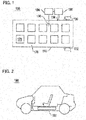
- Figure 1 is a schematic view illustrating a battery pack according to Embodiment 1
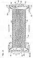
- Fig. 2 is a schematic view illustrating a usage of the battery pack
- Fig. 3 is a sectional view illustrating a main body unit illustrated in Fig. 1
- Fig. 4 is a sectional view illustrating a shape before decompression of a first lid member illustrated in Fig. 3 .
- the battery pack 100 according to the Embodiment 1 is applied to, for example, a power source of a vehicle 198 illustrated in Fig. 2 , and as illustrated in Figs. 1 and 3 , has a main body unit 110, a decompressor 190, and a control unit 194.
- the vehicle 198 is, for example, an electric car or a hybrid electric car.
- the battery pack 100 easily realizes, as will be explained later, a high energy density, and therefore, is able to extend a cruising distance per charge.
- the main body unit 110 includes a cell case 120 made of a rigid material, a first lid member 170 made of a flexible material, and a first cover plate 176.
- the "cell case 120 made of a rigid material” means that the cell case 120 is rigid and not easily deformed when external force is applied thereto, thereby sufficiently protecting a laminated body 140 arranged therein.
- the "first lid member 170 made of a flexible material” means that the first lid member 170 has flexibility to an extent that a differential pressure produced between an external pressure and an internal pressure of the cell case 120 by decompressing the inside of the cell case 120 (decreasing the internal pressure of the cell case 120 lower than the external pressure (at least atmospheric pressure)) may deform the first lid member 170.
- a second lid member to be explained later i.e., the "second lid member 173 made of a flexible material " means that the second lid member 173 has flexibility to an extent that a differential pressure produced between an external pressure and an internal pressure of the cell case 120 by decompressing the inside of the cell case 120 (decreasing the internal pressure of the cell case 120 lower than the external pressure (at least atmospheric pressure)) may deform the second lid member 173.
- the cell case 120 is made of a rigid material, has a substantially rectangular bottom face 122, a side wall part 124 surrounding the bottom face, and a top face forming a first opening 126, and arranges the laminated body 140 therein.
- the laminated body 140 has unit cells 10 laminated one on another, high-voltage tabs 150 and 152, and spacers 160 and 162.
- the first opening 126 is positioned to face a top face (first face) 142 of the laminated body 140 in terms of a laminated direction S of the unit cells 10.
- the high-voltage tabs 150 and 152 are plate-like coppers, are used to take current out of the laminated body 140 (laminated unit cells 10), and are in contact with a lower-most-layer unit cell 10 and an upper-most-layer unit cell 10, respectively.
- the spacers 160 and 162 are insulating sheets having a function of absorbing vibration applied to the laminated body 140 and are arranged on outer sides of the high-voltage tabs 150 and 152, respectively. Namely, the spacers 160 and 162 are positioned at the top face (first face) 142 and a bottom face (second face) 144 of the laminated body 140. The spacers 160 and 162 may be omitted as and when required.
- the first lid member 170 tightly closes the first opening 126, and according to the Embodiment 1, is made of an elastic film.
- the elastic film is made of, for example, urethane rubber.
- the first cover plate 176 has openings 178 and is arranged to cover and guard the first lid member 170.
- the first cover plate 176 is a backup plate that is made of a light material having good rigidity such as aluminum.
- the first cover plate 176 and first lid member 170 are fixed to the cell case 120 with the use of fastening members such as screws.
- the fastening members may also be used as fastening material to be used when installing the battery pack 100 in the vehicle 198.
- the decompressor 190 is a pressure applying device having a vacuum pump and is used to decrease an internal pressure of the cell case 120 lower than atmospheric pressure (external pressure).
- the control unit 194 is used to control the decompressor 190.
- the first lid member 170 covering the first opening 126 is, before the inside of the cell case 120 is decompressed (when an internal pressure of the cell case 120 is equal to atmospheric pressure), spaced apart from the laminated body 140 as illustrated in Fig. 4 .
- the decompressor 190 decompresses the inside of the cell case 120
- the first lid member 170 deforms due to a differential pressure between atmospheric pressure and the internal pressure of the cell case 120 while maintaining the tightly closing state, comes into contact with the spacer 160, and applies a pressure thereto according to the differential pressure.
- the first lid member 170 is configured to be deformable while tightly closing the first opening 126, deform when the inside of the cell case 120 is decompressed (the internal pressure of the cell case 120 becomes lower than atmospheric pressure), come into contact with the top face 142 of the laminated body 140, and apply a pressure based on the differential pressure to the contacting face.
- the pressing force on the laminated body 140 is a pressure based on the differential pressure between atmospheric pressure and the internal pressure of the cell case 120. Accordingly, without enlarging, for example, the decompressor (pressure applying device) 190 for decompressing the inside of the cell case 120, a total pressing pressure increases according to an increase in a unit cell (electrode) area. Even if the electrode area is large, it is possible to easily apply a proper pressing pressure to the laminated body 140.
- the laminated body 140 is strongly fixed to the high-rigidity cell case 120 with, as mentioned above, the pressure based on the differential pressure between atmospheric pressure and the internal pressure of the cell case 120. As a result, fixing the battery pack 100 to the vehicle 198 may stabilize the battery pack 100 as a whole.
- the cell case 120 further includes an insulating film layer 128, high-voltage connectors 130 and 132, a discharge connector 134, a pressure release valve 136, a pressure sensor 138, and low-voltage connectors (not illustrated).
- the insulating film layer 128 is formed on inner walls of the bottom face 122 and side wall part 124. Positioned on the insulating film layer 128 on the bottom face 122 is the spacer 162.
- the high-voltage connectors 130 and 132 are air-tightly attached to the side wall part 124 and are electrically connected to the high-voltage tabs 150 and 152.
- the discharge connector 134 is air-tightly attached to the side wall part 124 and is connected to piping from the decompressor 190. As a result, the decompressor 190 is able to discharge air from the inside of the cell case 120, thereby decompressing the inside of the cell case 120.
- the pressure release valve 136 is air-tightly attached to the side wall part 124, and when the internal pressure of the cell case 120 excessively increases due to, for example, an unexpected cause, is used to discharge a gas from the inside of the cell case 120 and decrease the internal pressure of the cell case 120.
- a gas discharging mechanism for the pressure release valve 136 is not particularly limited and is able to employ, for example, a metal thin film that cleaves at a predetermined pressure.
- the pressure sensor 138 is arranged inside the cell case 120 and is used to measure an internal pressure of the cell case 120.
- the low-voltage connectors (not illustrated) are airtightly attached to the side wall part 124 and are used to monitor (detect) a voltage of the unit cells contained in the laminated body 140.
- the decompressor 190 is controlled by the control unit 194 according to the internal pressure measured by the pressure sensor 138 and is configured to be activated if the internal pressure measured by the pressure sensor 138 is equal to or greater than an upper limit value, thereby decreasing the pressure in the cell case 120.
- the internal pressure upper limit value is set in consideration of the differential pressure between atmospheric pressure and the internal pressure of the cell case 120. This prevents an unexpected increase in the internal pressure of the cell case 120 and secures a good pressing pressure (a pressure based on the differential pressure).
- the internal pressure upper limit value is set to, for example, 0.25 atmospheres. In this case, a sufficient pressing pressure is obtainable.
- the decompressor 190 is configured to stop decreasing the pressure inside the cell case 120 if the internal pressure measured by the pressure sensor 138 reaches a lower limit value.
- the internal pressure lower limit value is set to, for example, 0.15 atmospheres. This level is equal to a multipurpose vacuum degree, and therefore, a decompressor (a vacuum source) used for another purpose can be used as the decompressor 190 for the system (the vehicle 198) in which the battery pack 100 is installed.
- the unit cells 10 contained in the laminated body 140 will be explained in detail.
- Figure 5 is a sectional view illustrating the laminated body illustrated in Fig. 3 and Fig. 6 is a sectional view illustrating positive electrode layers and negative electrode layers illustrated in Fig. 5 .
- each unit cell 10 laminated one on another in the laminated body 140 are connected in series. As illustrated in Fig. 6 , each unit cell is formed by sequentially laminating a positive electrode collector layer 20, a positive electrode layer 30, a separator 40, a negative electrode layer 50, and a negative electrode collector layer 60 and by sealing the peripheries thereof.
- the positive electrode collector layer 20 and negative electrode collector layer 60 each are a resin collector mainly containing conductive filler and resin. This configuration reduces the weight of the positive electrode collector layer 20 and negative electrode collector layer 60 and improves internal short-circuit resistivity, thereby enabling the use of high-capacity active materials.
- the conductive filler is made of, for example, aluminum, stainless steel, carbon such as graphite and carbon black, silver, gold, copper, and titanium.
- the resin is, for example, polyethylene, polypropylene, polyethylene terephthalate, polyether nitrile, polyimide, polyamide, polytetrafluoroethylene, styrene-butadiene rubber, polyacrylonitrile, polymethyl acrylate, polymethyl methacrylate, polyvinyl chloride, polyvinylidene fluoride, and mixtures thereof.
- the positive electrode collector layer 20 and negative electrode collector layer 60 are not limited to the resin collectors. They may be made of, for example, metal or conductive polymeric material.
- the metal is, for example, aluminum, nickel, iron, stainless steel, titanium, and copper.
- the conductive polymeric material is, for example, polyaniline, polypyrrole, polythiophene, polyacetylene, polyparaphenylene, polyphenylene vinylene, polyacrylonitrile, polyoxadiazole, and mixtures thereof.
- only one of the positive electrode collector layer 20 and negative electrode collector layer 60 may be made of a resin collector.
- the positive electrode layer 30 is a sheet-like electrode positioned between the positive electrode collector layer 20 and the separator 40, and as illustrated in Fig. 5 , contains positive electrode active material particles 32 and fibrous material 38.
- the positive electrode active material particles 32 each have a coating layer 33 on at least part of the surface thereof.
- the coating layer 33 is made of conductive adjuvant 35 and coating resin 34 and is able to relax a volumetric change of the positive electrode layer 30 and suppress an expansion of the electrode.
- the positive electrode active material particles 32 are made of complex oxide of lithium and transition metal, transition metal oxide, transition metal sulfide, conductive polymer, and the like.
- the complex oxide of lithium and transition metal is, for example, LiCoO 2 , LiNiO 2 , LiMnO 2 , and LiMn 2 O 4 .
- the transition metal oxide is, for example, MnO 2 and V 2 O 5 .
- the transition metal sulfide is, for example, MoS 2 and TiS 2 .
- the polymer is, for example, polyaniline, polyvinylidene fluoride, polypyrrole, polythiophene, polyacetylene, poly-p-phenylene, and polycarbazole.
- the coating resin 34 is preferably vinyl resin, urethane resin, polyester resin, and polyamide resin. As and when required, it may be epoxy resin, polyimide resin, silicon resin, phenol resin, melamine resin, urea resin, aniline resin, ionomer resin, and polycarbonate.
- the conductive adjuvant 35 is, for example, metal and carbon such as graphite and carbon black, and mixtures thereof.
- the metal is aluminum, stainless steel, silver, gold, copper, titanium, and alloys thereof.
- the carbon black is acetylene black, ketjenblack, furnace black, channel black, thermal lampblack, and the like. As and when required, two or more kinds of adjuvant may be used.
- the conductive adjuvant 35 is preferably, in view of electrical stability, silver, gold, aluminum, stainless steel, and carbon, more preferably, carbon.
- At least part of the fibrous material 38 forms conductive paths of the positive electrode layer 30 and is in contact with the positive electrode active material particles 32 around the conductive paths. Accordingly, electrons generated by the positive electrode active material (positive electrode active material particles 32) quickly reach the conductive paths and are smoothly guided to the positive electrode collector layer 20.
- the fibrous material 38 is, for example, carbon fiber such as PAN-based carbon fiber and pitch-based carbon fiber, metal fiber made from metal such as stainless steel, and conductive fiber.
- the conductive fiber is one made by uniformly dispersing metal or graphite in synthetic fiber, one made by coating the surface of organic fiber with metal, one made by coating the surface of organic fiber with resin containing conductive material, and the like.
- the carbon fiber is preferable among the conductive fibers.
- An electric conductance of the fibrous material 38 is preferably 50 mS/cm or over. In this case, resistance of the conductive paths is small, and therefore, the movement of electrons is more smoothly achieved from the positive electrode active material (positive electrode active material particles 32) existing away from the positive electrode collector layer 20.
- the electric conductance is obtainable by measuring a volume resistivity according to JIS R 7609 (2007) "Carbon Fiber - Way of Finding Volume Resistivity " and by taking an inverse of the volume resistivity.
- a mean fiber diameter of the fibrous material 38 is preferably 0.1 to 20 ⁇ m, more preferably, 0.5 to 2.0 ⁇ m.
- the mean fiber diameter is obtainable by picking up optional 10 pieces of fiber in a view field of 30 ⁇ m square, measuring a diameter at about the middle of each fiber piece, conducting such measurements in three view fields, and averaging the diameters of the total 30 fiber pieces.
- the sum of fiber lengths of the fibrous material 38 contained in an electrode unit volume is preferably 10000 to 50000000 cm/cm 3 , more preferably, 20000000 to 50000000 cm/cm 3 , further preferably, 1000000 to 10000000 cm/cm 3 .
- the negative electrode layer 50 is a sheet-like electrode positioned between the negative electrode collector layer 60 and the separator 40, and as illustrated in Fig. 5 , contains negative electrode active material particles 52 and fibrous material 58.
- the negative electrode active material particles 52 each have a coating layer 53 on at least part of the surface thereof.
- the coating layer 53 is made of conductive adjuvant 55 and coating resin 54 and is able to relax a volumetric change of the negative electrode layer 50 and suppress an expansion of the electrode.
- the negative electrode active material particles 52 are made of graphite, amorphous carbon, sintered high-molecular compound, kinds of coke, carbon fiber, conductive polymer, tin, silicon, metal alloy, complex oxide of lithium and transition metal, and the like.
- the sintered high-molecular compound is, for example, carbon material formed by sintering phenol resin and furan resin.
- the kinds of coke are, for example, pitch coke, needle coke, and petroleum coke.
- Conductive polymer is, for example, polyacetylene and polypyrrole.
- the metal alloy is, for example, lithium-tin alloy, lithium-silicon alloy, lithium-aluminum alloy, and lithium-aluminum-manganese alloy.
- the complex oxide of lithium and transition metal is, for example, Li 9 Ti 5 O 12 .
- the coating layer 53, coating resin 54, conductive adjuvant 55, and fibrous material 58 are configured substantially equal to the coating layer 33, coating resin 34, conductive adjuvant 35, and fibrous material 38, and therefore, their explanations are omitted. At least part of the fibrous material 58 forms conductive paths of the negative electrode layer 50 and is in contact with the negative electrode active material particles 52 around the conductive paths.
- the positive electrode layer 30 and negative electrode layer 50 with the above-mentioned structures may have a thickness of 150 to 1500 ⁇ m. As a result, they are able to contain many active materials to realize high capacity and improve energy density.
- the thickness of the positive electrode layer 30 and the thickness of the negative electrode layer 50 each are preferably 200 to 950 ⁇ m, more preferably, 250 to 900 ⁇ m.
- the separator 40 is a cellular (porous) insulator positioned between the positive electrode layer 30 and the negative electrode layer 50. When an electrolyte permeates, the separator 40 demonstrates ion permeability and electric conductivity.
- the electrolyte is, for example, a gel-polymer-based electrolyte having an electrolytic solution and host polymer.
- the electrolytic solution includes an organic solvent made of propylene carbonate and ethylene carbonate, and as a supporting electrolyte, lithium salt (LiPF 6 ).
- the organic solvent may be any other cyclic carbonate, chain carbonate such as dimethyl carbonate, and ether such as tetrahydrofuran.
- the lithium salt may be any other inorganic acid anionic salt and organic acid anionic salt such as LiCF 3 SO 3 .
- the host polymer is PVDF-HFP (copolymer of polyvinylidene fluoride and hexafluoropropylene) containing 10% HFP (hexafluoropropylene) copolymer.
- the host polymer may be any other polymer having no lithium ion conductivity or one having ion conductivity (solid polymer electrolyte).
- the polymer having no lithium ion conductivity is, for example, polyacrylonitrile and polymethylmethacrylate.
- the polymer having ion conductivity is, for example, polyethylene oxide and polypropylene oxide.
- Figure 7 is a sectional view illustrating the Modification 1 according to the Embodiment 1.
- the first lid member 170 is held and fixed between the first cover plate 176 and an upper end face 125 of the side wall part 124 of the cell case 120, thereby tightly closing the first opening 126 of the cell case 120.
- the upper end face 125 of the side wall part 124 of the cell case 120 to which the first lid member 170 is tightly attached is preferably provided with a stepped configuration. In this case, a good airtightness is achievable.
- Figure 8 is a sectional view illustrating the Modification 2 according to the Embodiment 1.
- the laminated body 140 in actual use will be exposed to shakes and vibrations in a lateral direction L orthogonal to the laminated direction S of the unit cells 10.
- a stopper 129 protruding in the lateral direction L on the side wall part 124 of the cell case 120, thereby stopping the movement of the laminated body 140 in the lateral direction L.
- the stopper 129 is arranged in the vicinity of a position where the first lid member 170 is in contact with the top face 142 of the laminated body 140.
- Figures 9 and 10 are sectional views explaining the Modifications 3 and 4, respectively, according to the Embodiment 1.
- the first lid member 170 is not limited to the single elastic film configuration and may have a multilayer structure having, on the surface or inside of an elastic film, a gas barrier metal layer to suppress the transmission of a gas such as water vapor.
- an elastic film 171 may be coated with, on one face, a metal layer 172, or as illustrated in Fig. 10 , a metal layer 172 may have, on each face, an elastic film 171.
- the metal layer 172 is made of, for example, aluminum so that the layer may contract or expand to some extent. It is also possible to coat each face of an elastic film 171 with a metal layer 172.
- Figure 11 is a sectional view illustrating the Modification 5 according to the Embodiment 1.
- the high-voltage tabs 150 and 152 each are preferred to have a two-layer structure including an elastic layer 153 and a support layer 154 arranged on one face of the elastic layer 153.
- the elastic layer 153 has elasticity to deform according to a surface shape of the unit cells 10 and is positioned to face the laminated unit cells 10.
- the elastic layer 153 is able to decrease contact resistance with respect to the uppermost (contacting) unit cell 10.
- the support layer 154 is made of, for example, plate-like copper to secure strength and rigidity required for the high-voltage tabs 150 and 152. Namely, the strength and rigidity of the support layer 154 are greater than the strength and rigidity of the elastic layer 153.
- the elastic layer 153 includes, for example, a conductive cloth 153A, a conductive urethane foam 153B, and a conductive nonwoven cloth 153C.
- the conductive cloth 153A faces the support layer 154 and is selected in consideration of adhesiveness with respect to the support layer 154.
- the conductive nonwoven cloth 153C faces the unit cells 10 and is selected in consideration of adhesiveness with respect to the unit cells 10.
- the conductive urethane foam 153B is positioned between the conductive cloth 153A and the conductive nonwoven cloth 153C and is selected in consideration of deformability according to the surface shape (unevenness) of the unit cells 10.
- Figure 12 is a sectional view illustrating the Modification 6 according to the Embodiment 1.
- the laminated body 140 is preferred to be divided into a plurality of blocks 141A and 141B in terms of the laminated direction S with a conductive elastic member 146 interposed between the adjacent blocks.
- the elastic member 146 is substantially a plate and has elasticity to deform according to the surface shape of the uppermost layer unit cell 10 of each of the blocks 141A and 141B, to reduce contact resistance inside the laminated body 140.
- the number of divided blocks of the laminated body 140 is not particularly limited and is properly set according to, for example, the number of laminations of the unit cells 10 and the area of each unit cell 10 (electrode).
- Figure 13 is a sectional view illustrating the Modification 7 according to the Embodiment 1.
- a conductive layer 70 between the adjacent unit cells 10. This can be reduce contact resistance between the unit cells 10.
- Figure 14 is a sectional view illustrating the Modification 8 according to the Embodiment 1.
- the main body unit 110 further includes, as illustrated in Fig. 14 , a second lid member 173 made of flexible material and a second cover plate 177.
- the cell case 120 has, instead of the bottom face 122, a second opening 127.
- the second opening 127 is positioned to face the bottom face (second face) 144 of the laminated body 140 and is closed with the second lid member 173.
- the second lid member 173 is deformable while tightly closing the second opening 127, and when the decompressor 190 reduces pressure inside the cell case 120 (reducing the internal pressure of the cell case 120 lower than atmospheric pressure), deforms to come into contact with the spacer 162 and apply the differential pressure thereto.
- the second lid member 173 is configured to come into contact with the bottom face 144 of the laminated body 140 and apply a pressure based on the differential pressure to the contacting face.
- the second cover plate 177 has openings 179 and is arranged to cover and guard the second lid member 173.
- the Embodiment 1 decreases pressure inside the cell case (decreasing an internal pressure of the cell case lower than an external pressure (atmospheric pressure)) so that a pressure based on a differential pressure between the external pressure and the internal pressure of the cell case is applied by the first lid member, which keeps an airtightly closing state and is deformed, to the first face of the laminated body in which the unit cells are laminated one on another.
- the pressing pressure on the laminated body in which the unit cells are laminated one on another is created by the pressure based on the differential pressure.
- the decompressor pressure applying device
- a total pressing pressure increases according to an increase in the area of the unit cell (electrode). It is possible, therefore, to provide a battery pack that is capable of, even if the area of each electrode is large, easily applying a proper pressing pressure to the laminated body in which the unit cells are laminated one on another.
- a part (bottom face) of the cell case facing the second face of the laminated body is omissible.
- the first lid member may be made of an elastic film to realize a simple configuration.
- the elastic film is provided with a metal layer on the surface or inside thereof, a gas barrier capability will improve.
- a stopper is arranged to stop the movement of the laminated body in a lateral direction orthogonal to the laminated direction of the unit cells, an influence on the laminated body will be suppressed when the battery pack is shaken or vibrated in the lateral direction.
- the decompressor decreases pressure inside the cell case, to prevent an unexpected increase in the internal pressure of the cell case and secure a good pressing pressure (a pressure based on the differential pressure).
- the internal pressure level is equal to a multipurpose vacuum level. Accordingly, a system in which a battery pack must be installed is able to employ a decompressor (vacuum source) of any other purpose as the decompressor of the battery pack.
- the high-voltage tab is configured to have an elastic layer having elasticity to deform according to a surface shape of the unit cells and a support layer having strength and rigidity greater than the strength and rigidity of the elastic layer, contact resistance between the high-voltage tab and the unit cells can be reduced.
- a pressure release valve for decreasing the internal pressure of the cell case is arranged, it is possible to suppress an excessive increase in the internal pressure of the cell case due to an unexpected cause.
- the laminated body is divided into a plurality of blocks in terms of the laminated direction and if a plate-like elastic member having elasticity to deform according to a surface shape of the blocks is arranged between the adjacent blocks, contact resistance inside the laminated body can be reduced.
- the thickness of the positive electrode layer and the thickness of the negative electrode layer are set to be equal to or greater than 150 ⁇ m, the capacity and energy density of each unit cell can be increased.
- the fibrous material is carbon fiber, a good electric conductance is obtainable.
- each collector layer becomes lightweight and improves internal short-circuit resistivity to make it possible to employ an active material of higher capacity.
- the battery pack is capable of easily applying a proper pressing pressure to the laminated body in which the unit cells are laminated one on another.
- the area of each electrode of each unit cell can be increased to easily realize a high energy density. If used as a power source for a vehicle, the battery pack can extend, for example, a cruising distance per charge.
- Embodiment 2 will be explained.
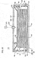
- Figure 15 is a sectional view illustrating a battery pack according to the Embodiment 2 and Fig. 16 is a plan view illustrating a before-decompression shape of a first lid member illustrated in Fig. 15 .
- a differential pressure between atmospheric pressure and the internal pressure of the cell case 120 deforms the first lid member that keeps a tightly closed state, so that the first lid member comes into contact with a first face of the laminated body 140 and applies a pressure based on the differential pressure to the contacting face.
- This first lid member is not limited to the configuration realized by the first lid member 170 made of an elastic film.
- the first lid member 180 illustrated in Figs. 15 and 16 is employable. This also realizes a simple configuration.
- the Embodiment 2 except the first lid member 180 is substantially the same as the Embodiment 1, and therefore, explanations of the other parts will appropriately be omitted.
- the first lid member 180 has a plate-like part 181 and a freely expandable and contractible part 182.
- the plate-like part 181 has a shape substantially agreeing with the top face (first face) 142 of the laminated body 140.
- the freely expandable/contractible part 182 surrounds the periphery of the plate-like part 181, and when the inside pressure of the cell case 120 is decreased, expands to bring the plate-like part 181 into contact with the top face 142 of the laminated body 140, thereby applying a differential-pressure-based pressure to the contacting face.
- the freely expandable/contractible part 182 has a bellows structure.
- the freely expandable/contractible part 182 can have a simple structure.
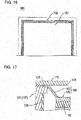
- Figure 17 is a sectional view illustrating the Modification 1 according to the Embodiment 2.
- the freely expandable and contractible part 182 of the first lid member 180 is held and fixed between the first cover plate 176 and an upper end face 125 of the side wall part 124 of the cell case 120, thereby tightly closing the first opening 126 of the cell case 120.
- the upper end face 125 of the side wall part 124 of the cell case 120 to which the freely expandable/contractible part 182 is tightly attached is preferably provided with a stepped configuration as illustrated in Fig. 17 .
- Figure 18 is a sectional view illustrating the Modification 2 according to the Embodiment 2.
- a stopper 129 protruding in the lateral direction L is preferred to be arranged on the side wall part 124 of the cell case 120 similar to the Modification 2 ( Fig. 8 ) of the embodiment 1, to stop the movement of the laminated body 140 in the lateral direction L.
- Figure 19 is a sectional view illustrating the Modification 3 according to the Embodiment 2.
- the Embodiment 2 is able to apply, to the bottom face (second face) 144 of the laminated body 140, a pressure based on a differential pressure between atmospheric pressure and an internal pressure of the cell case 120.
- the main body unit 110 further includes a second lid member 183 and a second cover plate 177.
- the second lid member 183 has a plate-like part 184 and a freely expandable/contractible part 185.
- the freely expandable/contractible part 185 expands to bring the plate-like part 184 into contact with the bottom face (second face) 144 of the laminated body 140, thereby applying the pressure based on the differential pressure thereto.
- the Embodiment 2 employs the first lid member of simple structure having the plate-like part and freely expandable/contractible part, to apply a pressure based on a differential pressure between the external pressure (atmospheric pressure) and internal pressure of the cell case to the first face of the laminated body in which the unit cells are laminated one on another. Accordingly, without enlarging the decompressor (pressure applying device) that decompresses the inside of the cell case and decreases the internal pressure of the cell case lower than the external pressure, a total pressing pressure increases according to an increase in a unit cell (electrode) area. As a result, the Embodiment 2 is also capable of providing a battery pack that is able to apply, even if the area of each electrode is large, a proper pressing pressure to the laminated body in which the unit cells are laminated one on another.
- the freely expandable/contractible part has a bellows structure, and therefore, is realizable with a simple structure.
- Embodiment 3 will be explained.
- Figure 20A is a sectional view illustrating a battery pack according to the Embodiment 3.
- a first lid member is in a deformed state due to a differential pressure.
- Figure 20B schematically illustrates, in a plan view of unit cells seen in a laminated direction, a relationship between an area in which the first lid member is in contact with the laminated body and a part of the unit cells that contributes to power generation.
- Figure 21 is a sectional view illustrating a sealed state of the peripheries of the unit cells contained in the laminated body.
- the first lid member is configured to, when the inside of a cell case 120 is decompressed (to decrease the internal pressure of the cell case 120 lower than atmospheric pressure (external pressure)), keep a tightly closing state, deform due to a differential pressure between atmospheric pressure and the internal pressure of the cell case 120, come into contact with a first face 142 of the laminated body 140, and apply a pressure based on the differential pressure to the contacting face.
- a first lid member is not limited to the first lid member 170 made of an elastic film (Embodiment 1) or the first lid member 180 having the plate-like part 181 and freely expandable/contractible part 182 (Embodiment 2).
- the first lid member 200 illustrated in Fig. 20A is employable.
- the laminated body 140 has the laminated unit cells 10 and high-voltage tabs 150 and 152. No spacers 160 and 162 are arranged. Omitting the spacers 160 and 162 can reduce the height dimension of the battery pack 100.
- the Embodiment 3 except the first lid member 200 and spacers 160 and 162 is substantially the same as the Embodiments 1 and 2, and therefore, explanations of the other configurations are omitted.
- the first lid member 200 is a single-layer metal plate. This first lid member 200 elastically deforms when the internal pressure of the cell case 120 is lower than the external pressure of the cell case 120, comes into contact with the first face 142 of the laminated body 140, and applies a pressure based on the differential pressure to the contacting face. With the single-layer metal plate, the first lid member 200 is realizable in a simple structure.
- the unit cells 10 according to the Embodiment 3 include a seal part 80 that seals the peripheries of the unit cells 10.
- the unit cells 10 are connected in series, and in each of which, a positive electrode collector layer 20, a positive electrode layer 30, a separator 40, a negative electrode layer 50, and a negative electrode collector layer 60 are sequentially laminated one on another.
- the peripheries of the positive electrode layers 30 and negative electrode layers 50 are sealed with the seal part 80.
- the unit cells 10 except the seal part 80 according to the Embodiment 3 are substantially the same as the unit cells 10 of the Embodiment 1, and therefore, explanations of the other configurations will suitably be omitted.
- the seal part 80 is arranged to surround the peripheries of the positive electrode layers 30 and negative electrode layers 50.
- Material to form the seal part 80 may be any that has an insulating capability, sealing capability, heat resistance under operating temperatures of the battery, and the like.
- the seal part 80 is made of, for example, thermoplastic resin. More precisely, urethane resin, epoxy resin, polyethylene resin, polypropylene resin, polyimide resin, and the like are employable.
- a part of the laminated unit cells 10 that contributes to power generation is, as represented with a reference numeral 81 in Fig. 21 , an area inside the peripheries of the unit cells 10 where the seal part 80 is arranged.
- the "part of the laminated unit cells 10 that contributes to power generation” is hereunder simply referred to as the power generation area 81.
- a reference mark c indicates a clearance between an inner face of the cell case 120 and a side face of the laminated body 140.
- a reference mark s1 indicates a length of the seal part 80 from the side face of the laminated body 140, i.e., a length of a part of the laminated unit cells 10 that has no contribution to power generation.
- a reference mark St indicates a displacement of the first lid member 200 along the laminated direction of the unit cells 10 from a state in which an internal pressure of the cell case 120 is equal to an external pressure of the cell case 120 up to a state in which decompression brings the first lid member 200 in contact with the first face 142 of the laminated body 140.
- the "displacement of the first lid member 200 along the laminated direction of the unit cells 10" is hereafter also referred to as the stroke.
- a reference mark Pr indicates a location where the first lid member 200 starts to come into contact with the first face 142 of the laminated body 140.
- a reference mark r indicates a horizontal length from the inner face of the cell case 120 to Pr.
- a relationship between an area in which the first lid member 200 is in contact with the laminated body 140 and the power generation area 81 will be explained.
- the location Pr where the first lid member 200 starts to come into contact with the laminated body 140 is indicated with a two-dot chain line and the power generation area 81 with a broken line.
- the first lid member 200 comes into contact with, in an area larger than the power generation area 81, the first face 142 of the laminated body 140.
- the unit cells 10 of the Embodiment 3 include the seal part 80 to seal the peripheries of the unit cells 10 and the power generation area 81 is inside the seal part 80. Accordingly, the first lid member 200 is in contact with, in at least a part of the seal part 80 and in the power generation area 81, the first face 142 of the laminated body 140.
- the power generation area 81 includes a part that is in contact with the first lid member 200 and a part that is not in contact therewith, these parts will have different resistance values to cause different output voltage values. This will cause a local deterioration of the unit cells 10.
- the first lid member 200 is in contact with the first face 142 of the laminated body 140 (R ⁇ r), and therefore, the first lid member 200 is able to uniformly pressurize the whole of the part corresponding to the power generation area 81 (uniform pressurization characteristic). This can suppress the local deterioration of the unit cells 10.
- the first lid member 200 is preferred to satisfy the uniform pressurization characteristic to uniformly pressurize the part corresponding to the power generation area 81, and in addition, have a large stroke St.
- Setting a large stroke means allowing a large height tolerance for the laminated body 140, i.e., allowing a large thickness tolerance for the unit cells 10. Allowing a large thickness tolerance for the unit cells 10 relatively relaxes dimensional management when manufacturing the unit cells 10. This makes the production of the unit cells 10 relatively easy and improves product yields.
- the Embodiment 3 is also modifiable like the Embodiments 1 and 2.
- the main body unit 110 further includes a second lid member and a second cover plate 177 (refer to Figs. 14 and 19 ).
- the second lid member is made of a single-layer metal plate. The second lid member elastically deforms when the internal pressure of the cell case 120 is lower than the external pressure of the cell case 120, comes into contact with the bottom face (second face) 144 of the laminated body 140, and applies a pressure based on the differential pressure thereto.
- the Embodiment 3 employs the first lid member of simple structure made of a single-layer metal plate to apply a pressure based on a differential pressure between an external pressure (atmospheric pressure) and an internal pressure of the cell case to the first face of the laminated body in which the unit cells are laminated one on another.
- an external pressure atmospheric pressure
- an internal pressure of the cell case to the first face of the laminated body in which the unit cells are laminated one on another.
- the decompressor pressure applying device
- a total pressing pressure will increase as a unit cell (electrode) area increases.
- the Embodiment 3 is also able to provide a battery pack that is capable of easily applying a proper pressing pressure, even if the area of each electrode is large, to the laminated body in which the unit cells are laminated one on another.
- the first lid member comes into contact with, in an area larger than the part of the laminated unit cells that contributes to power generation, the first face of the laminated body.
- This configuration is able to uniformly pressurize the whole of the power generation contributing part and suppress an occurrence of local deterioration of the unit cells.
- the unit cells are provided with the seal part for sealing the peripheries of the unit cells and the part of the unit cells contributing to power generation is inside the seal part.
- the first lid member is in contact with, in at least a part of the seal part and in the power generation contributing part, the first face of the laminated body.
- the first lid members 170 and 180 are in contact with the first face 142 from an end of the laminated body 140.
- the first lid members 170 and 180 of the Embodiments 1 and 2 are in contact with, in an area larger than a part of the laminated unit cells that contributes to power generation, the first face 142 of the laminated body 140. Accordingly, the Embodiments 1 and 2 are also able to uniformly pressurize the whole of the power generation contributing part and suppress an occurrence of local deterioration of the unit cells.
- the material and thickness of the first lid member When selecting the material and thickness of the first lid member, it is necessary to consider that a pressure leakage is small and that a vacuum keeping characteristic is excellent. Further, as explained above, it is necessary to consider that the first lid member satisfies the uniform pressurization characteristic to uniformly pressurize the part corresponding to the power generation area and allows to set a large stroke.
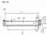
- Figure 22 is a schematic view illustrating a testing device used to select the material and thickness of the first lid member.
- the testing device 210 has a box-shaped lower case 212 having an accommodation space 211, a frame-shaped upper case 213 fixed to an upper part of the lower case 212, and a plate body 214 accommodated in the accommodation space 211.
- the periphery of a test piece 215 for the first lid member is held and fixed between the lower case 212 and the upper case 213.
- Airtightly attached to a side wall of the lower case 212 is a discharge connector 216.
- the discharge connector 216 is connected to a vacuum pump 217.
- the vacuum pump 217 discharges air from the inside of the lower case 212, thereby decompressing the inside of the lower case 212.
- the lower case 212 is a model of the cell case 120 and the dimensions (a length dimension L1 in a left-right direction in the drawing and a width dimension in a direction orthogonal to the drawing) of the accommodation space 211 are equal to the dimensions of the cell case 120.
- the length and width of the plate body 214 are equal to the dimensions of the laminated body 140.
- the plate body 214 is formed by laminating a plurality of acrylic plates one on another. By changing the number of the laminated acrylic plates, the height dimension of the plate body 214 can be changed. The height of the plate body 214 may be lowered by a predetermined dimension from a height equal to the height of the lower case 212.
- changing the number of the laminated acrylic plates may set a displacement, i.e., a stroke of the test piece 215 at the time of decompression.
- the stroke can be set from 0.5 mm to 10 mm at a pitch of 0.5 mm.
- a reference mark c corresponds to a clearance between the inner face of the cell case 120 and the side wall of the laminated body 140 and is set to 5 mm.
- a reference mark s1 corresponds to the length of the seal part 80 from the side face of the laminated body 140, i.e., the length of the part of the laminated unit cells 10 that has no contribution to power generation and is set to 10 mm.
- a reference mark St indicates a displacement of the test piece 215 at the time of decompression, i.e., the stroke.
- a reference mark Pr indicates a location where the test piece 215 starts to come into contact with a top face of the plate body 214.
- a reference mark r indicates a horizontal length from the inner side face of the lower case 212 up to Pr.
- test piece 215 for the first lid member prepared as the test piece 215 for the first lid member are a test piece 215 made of a single-layer metal plate (refer to Fig. 20A of the Embodiment 3) and a test piece 215 made of an elastic film having a multilayer structure (refer to Fig. 10 of the Modification 4 of the Embodiment 1).
- test piece 215 made of a single-layer metal plate are prepared as the test piece 215 made of a single-layer metal plate.
- SUS304 stainless steel
- A1050-H24 aluminum material having a tensile strength of 110 N/mm 2 and thicknesses of 0.1 mm, 0.15 mm, and 0.2 mm, respectively.
- Test piece 215 made of an elastic film having a multilayer structure is a laminated material having a base material on each of which an elastic layer is arranged.
- the base material is an aluminum material having a tensile strength of 110 N/mm 2 and the elastic layer is made of PET, nylon, and PP material.
- the laminated material as a whole has a tensile strength of 70 N/mm 2 and a thickness of 0.18 mm.
- the first lid member must come into contact with the first face 142 of the laminated body 140.
- a maximum value of the stroke is preferred to be large subject to satisfying the uniform pressurization characteristic.
- the plate body 214 with a stroke of 0.5 mm is accommodated in the lower case 212, the test piece 215 is fixed, and the inside of the lower case 212 is decompressed up to -90 kPa Gauge. This state is maintained for five minutes and a pressure leakage (kPa/min) is measured.
- the horizontal length r from the inner side face of the lower case 212 up to Pr is measured with a scale. In connection with an area in which the test piece 215 is in contact with the top face of the plate body 214, it is confirmed that the test piece 215 is in contact with the top face of the plate body 214.
- the vacuum keeping characteristic or the uniform pressurization characteristic is "OK"
- the inside of the lower case 212 is opened to the atmosphere, the plate body 214 with a stroke of 1 mm (an increase of 0.5 mm) is accommodated in the lower case 212, the test piece 215 is fixed, and the inside of the lower case 212 is decompressed up to -90 kPa Gauge. This state is maintained for five minutes and whether or not the vacuum keeping characteristic is good is tested according to the above-mentioned threshold value.
- the horizontal length r is measured with a scale, and according to the above-mentioned value of R, whether or not the uniform pressurization characteristic is good is determined.
- the vacuum keeping characteristic must be "OK" at a stroke of at least 6 mm and the maximum stroke value under the condition of satisfying the uniform pressurization characteristic must "exceed 1 mm".
- the maximum stroke value exceeds 1 mm, a tolerance allowed for the thickness dimension of the unit cells 10 becomes larger to make the production of the unit cells relatively easy and contribute to improving product yields.
- the maximum stroke value is equal to or lower than 1 mm, the tolerance allowed for the thickness dimension of the unit cells 10 is too small so that the production easiness of the unit cells 10 and the product yield improvement will not be achieved.
- the stroke is at least 6 mm and the vacuum keeping characteristic is "OK”, airtightness will be maintained for a relatively long period. If the stroke is 6 mm and the vacuum keeping characteristic is "NG”, it is not preferable because the frequency of decompressing operation will increase.
- the first lid member made of the above-mentioned single-layer metal plate demonstrates, first of all, little pressure leakage, i.e., an excellent vacuum keeping characteristic to keep a differential pressure. With this, an elastic deformation of the first lid member due to the differential pressure between an external pressure and an internal pressure of the cell case can stably be maintained. Further, it is possible to extend the stroke that satisfies the uniform pressurization characteristic. This results in increasing a tolerance allowed for the thickness of the unit cells 10 and relatively relaxing dimensional management when manufacturing the unit cells 10. As a result, the manufacturing becomes relatively easy and product yields improve.
- the elastic film is selectable from a laminated material that has an elastic layer arranged on each face of a base material and has a tensile strength of 70 N/mm 2 and a thickness of 0.18 mm.
- the first lid member made from the above-mentioned laminated material is capable of, like the one mentioned above, stably maintaining an elastic deformation of the first lid member due to a differential pressure between an external pressure and an internal pressure of the cell case.
- it increases a tolerance allowed for the thickness dimension of the unit cells 10, makes the manufacturing thereof relatively easy, and contributes to improving the product yields.
- the first lid member in a state deformed by at least 1 mm in terms of the laminated direction from a state in which an internal pressure of the cell case is equal to an external pressure of the cell case, is in contact with the first face of the laminated body.
- the first lid member satisfies the condition of uniformly pressurizing the whole of an area corresponding to the power generation area 81, and at the same time, is able to increase a displacement (stroke) along the laminated direction of the unit cells 10.
- a tolerance allowed for the thickness dimension of the unit cells 10 becomes larger and dimensional management when manufacturing the unit cells 10 is relatively relaxed. As a result, the manufacturing becomes relatively easy and product yields improve.
- the first lid member has a tensile strength of 70 to 110 N/mm 2 and a thickness of 0.15 to 0.2 mm.
- the first lid member having such a constitution demonstrates little pressure leakage and an excellent vacuum keeping characteristic to maintain a differential pressure.
- the differential pressure between an external pressure and an internal pressure of the cell case can stably maintain an elastic deformation of the first lid member.
- the condition of uniformly pressurizing the whole of an area corresponding to the power generation area 81 is satisfied and a displacement (stroke) along the laminated direction of the unit cells 10 can be increased. This results in increasing a tolerance allowed for the thickness dimension of the unit cells 10 and relatively relaxing dimension management when manufacturing the unit cells 10. As a result, the manufacturing becomes relatively easy and product yields improve.
- Embodiment 4 will be explained.
- Figure 23 is a sectional view illustrating a battery pack according to the Embodiment 4.
- a first lid member is in a deformed state due to a differential pressure.
- the present invention is not limited to the configuration that applies, to the laminated body 140, a pressure based on a differential pressure between atmospheric pressure serving as an external pressure and an internal pressure of the cell case 120. It is possible to apply, to the laminated body 140, a pressure based on a differential pressure between an external pressure higher than atmospheric pressure and an internal pressure of the cell case 120.
- a sealing plate 220 is arranged to cover the first lid member 200.
- the sealing plate 220 is made of light material such as aluminum having a good rigidity.
- the sealing plate 220 and first lid member 200 are fixed to a cell case 120 with the use of fastening members such as screws.
- the fastening members may also be used as fastening members to install the battery pack 100 in the vehicle 198.
- the Embodiment 4 except the sealing plate 220 is substantially the same as the Embodiment 3, and therefore, explanations of the other configurations thereof will be omitted.
- a space 221 between the sealing plate 220 and the first lid member 200 is tightly closed.
- the sealing plate 220 is airtightly provided with an air supply connector 222.
- the air supply connector 222 is connected to a pump 223 that supplies air whose pressure is higher than atmospheric pressure.
- the pump 223 supplies the air into the space 221 between the sealing plate 220 and the first lid member 200
- the first lid member 200 receives the external pressure that is higher than atmospheric pressure.
- the first lid member 200 is able to apply a pressure based on a differential pressure between the external pressure higher than atmospheric pressure and an internal pressure of the cell case 120 to the laminated body 140.
- the main body unit 110 further includes a second lid member and a sealing plate 220.
- the second lid member is made of, like the first lid member 200, a single-layer metal plate.
- the pump 223 supplies air to apply the external pressure higher than atmospheric pressure to the second lid member.
- the second lid member elastically deforms due to the differential pressure between the external pressure higher than atmospheric pressure and the internal pressure of the cell case 120 and comes into contact with the bottom face (second face) 144 of the laminated body 140, thereby applying thereto the pressure based on the differential pressure.
- the Embodiment 4 supplies air having an external pressure higher than atmospheric pressure, to decrease the internal pressure of the cell case (decreases the internal pressure of the cell case lower than atmospheric pressure), so that a pressure based on a differential pressure between the external pressure higher than atmospheric pressure and the internal pressure of the cell case is applied by the first lid member deformed in a tightly closed state to the first face of the laminated body in which the unit cells are laminated one on another.
- the pressing force to the laminated body in which the unit cells are laminated one on another is formed from the pressure based on the differential pressure, and when a unit cell (electrode) area increases, a total pressing pressure increases. Even if the area of each electrode is large, it is possible to provide a battery pack that is able to easily apply an appropriate pressing pressure to the laminated body in which the unit cells are laminated one on another.
- the present invention is not limited to the above-mentioned embodiments and is variously modifiable within the scope of claims.
- the Modifications 1 to 8 according to the Embodiment 1 may properly be combined and applied to the Embodiment 1 and the Modifications 1 to 3 of the Embodiment 2 and the Modifications 3 to 7 of the Embodiment 1 may properly be combined and applied to the Embodiment 2.
- the Embodiments 1 to 4 and the Modifications of the Embodiments 1 to 4 may properly be combined to form other embodiments.
Landscapes
- Chemical & Material Sciences (AREA)
- Chemical Kinetics & Catalysis (AREA)
- Electrochemistry (AREA)
- General Chemical & Material Sciences (AREA)
- Engineering & Computer Science (AREA)
- Manufacturing & Machinery (AREA)
- Composite Materials (AREA)
- Inorganic Chemistry (AREA)
- Materials Engineering (AREA)
- Secondary Cells (AREA)
- Sealing Battery Cases Or Jackets (AREA)
- Battery Mounting, Suspending (AREA)
- Battery Electrode And Active Subsutance (AREA)
- Gas Exhaust Devices For Batteries (AREA)
- Connection Of Batteries Or Terminals (AREA)
Applications Claiming Priority (2)
| Application Number | Priority Date | Filing Date | Title |
|---|---|---|---|
| JP2016047609 | 2016-03-10 | ||
| PCT/JP2017/009325 WO2017154999A1 (ja) | 2016-03-10 | 2017-03-08 | 電池パック |
Publications (3)
| Publication Number | Publication Date |
|---|---|
| EP3428992A1 true EP3428992A1 (de) | 2019-01-16 |
| EP3428992A4 EP3428992A4 (de) | 2019-02-20 |
| EP3428992B1 EP3428992B1 (de) | 2020-04-29 |
Family
ID=59909079
Family Applications (1)
| Application Number | Title | Priority Date | Filing Date |
|---|---|---|---|
| EP17763339.3A Active EP3428992B1 (de) | 2016-03-10 | 2017-03-08 | Batteriepack |
Country Status (5)
| Country | Link |
|---|---|
| US (1) | US11522242B2 (de) |
| EP (1) | EP3428992B1 (de) |
| JP (1) | JP6826916B2 (de) |
| KR (1) | KR20180120243A (de) |
| CN (1) | CN108780856B (de) |
Families Citing this family (21)
| Publication number | Priority date | Publication date | Assignee | Title |
|---|---|---|---|---|
| JP6842889B2 (ja) * | 2016-11-16 | 2021-03-17 | 日産自動車株式会社 | 電池 |
| JP6960787B2 (ja) * | 2017-07-11 | 2021-11-05 | 日産自動車株式会社 | 電池 |
| JP6960271B2 (ja) * | 2017-08-10 | 2021-11-05 | 日立造船株式会社 | 全固体電池 |
| KR102410663B1 (ko) * | 2018-07-06 | 2022-06-17 | 주식회사 엘지에너지솔루션 | 이차전지 및 그 제조방법 |
| JP7103239B2 (ja) * | 2019-01-09 | 2022-07-20 | トヨタ自動車株式会社 | 二次電池の拘束構造 |
| JP7165303B2 (ja) * | 2019-03-08 | 2022-11-04 | トヨタ自動車株式会社 | 電池パックのリーク検査方法およびリーク検査装置 |
| CN110828746B (zh) * | 2020-01-13 | 2020-07-10 | 比亚迪股份有限公司 | 一种电池包和电动车 |
| CN113193272B (zh) * | 2020-01-13 | 2023-06-13 | 比亚迪股份有限公司 | 一种电池、电池模组、电池包和电动车 |
| CN212625802U (zh) * | 2020-01-13 | 2021-02-26 | 比亚迪股份有限公司 | 一种电池包和电动车 |
| CN113193271B (zh) * | 2020-01-13 | 2023-06-13 | 比亚迪股份有限公司 | 一种电池、电池模组、电池包和电动车 |
| CN212587593U (zh) * | 2020-01-13 | 2021-02-23 | 比亚迪股份有限公司 | 一种电池、电池模组、电池包和电动车 |
| CN110828744B (zh) * | 2020-01-13 | 2020-07-10 | 比亚迪股份有限公司 | 一种电池、电池包和电动车 |
| CN113285149A (zh) * | 2020-02-18 | 2021-08-20 | 比亚迪股份有限公司 | 一种电池、电池模组、电池包和电动车 |
| CN113335080A (zh) * | 2020-02-18 | 2021-09-03 | 比亚迪股份有限公司 | 电池包及车辆 |
| CN112701341B (zh) * | 2020-12-28 | 2022-02-25 | 广东微电新能源有限公司 | 电池及电子设备 |
| CN113540471A (zh) * | 2021-07-13 | 2021-10-22 | 四川大学 | 三维多孔集流体材料及其制备方法和应用 |
| JP2023080893A (ja) * | 2021-11-30 | 2023-06-09 | トヨタ自動車株式会社 | 蓄電モジュールの製造方法及び蓄電モジュール |
| KR20230171691A (ko) * | 2022-06-14 | 2023-12-21 | 에스케이온 주식회사 | 이차전지 내부압력 측정 방법 |
| CN115441121B (zh) * | 2022-11-08 | 2023-02-07 | 楚能新能源股份有限公司 | 一种延缓热失控的电池模组、电池包及电动车 |
| US20240178472A1 (en) | 2022-11-24 | 2024-05-30 | Toyota Jidosha Kabushiki Kaisha | Secondary battery system of vehicle |
| CN116207433B (zh) * | 2023-05-05 | 2023-07-14 | 广汽埃安新能源汽车股份有限公司 | 电池单体、动力电池包及用电设备 |
Family Cites Families (20)
| Publication number | Priority date | Publication date | Assignee | Title |
|---|---|---|---|---|
| US5912090A (en) * | 1996-03-08 | 1999-06-15 | Hitachi Maxell, Ltd. | Nickel-hydrogen stacked battery pack |
| JP3424499B2 (ja) * | 1997-05-26 | 2003-07-07 | 新神戸電機株式会社 | 角形非水電解液二次電池 |
| AU2003228041A1 (en) * | 2002-05-08 | 2003-11-11 | Ilion Technology | Packaging device for an electrochemical device and method for making the same |
| JP4233830B2 (ja) * | 2002-09-09 | 2009-03-04 | パナソニック株式会社 | 扁平角形電池 |
| KR100614381B1 (ko) * | 2004-07-29 | 2006-08-21 | 삼성에스디아이 주식회사 | 리튬 이온 이차 전지 |
| EP1970982A4 (de) * | 2005-10-03 | 2010-01-13 | Tdk Lambda Corp | Batteriepack |
| JP5114950B2 (ja) | 2006-02-13 | 2013-01-09 | 日産自動車株式会社 | 電池モジュール、組電池及びそれらの電池を搭載した車両 |
| JP5456954B2 (ja) * | 2006-11-30 | 2014-04-02 | 日産自動車株式会社 | 双極型二次電池のモジュール構造 |
| DE102009058444A1 (de) | 2009-12-16 | 2011-06-22 | Li-Tec Battery GmbH, 01917 | Batteriegehäuse zur Aufnahme von elektrochemischen Energiespeichereinrichtungen |
| JP5119277B2 (ja) * | 2010-01-12 | 2013-01-16 | 株式会社日立製作所 | リチウム二次電池用電極及びその製造方法 |
| US20110311862A1 (en) * | 2010-06-21 | 2011-12-22 | Samsung Sdi Co., Ltd. | Secondary battery |
| US9812686B2 (en) | 2010-06-30 | 2017-11-07 | Gs Yuasa International Ltd. | Manufacturing method of secondary battery, secondary battery, and assembled battery |
| CN103026534B (zh) * | 2010-07-26 | 2015-09-16 | 日产自动车株式会社 | 双极型电池 |
| JP2012114066A (ja) * | 2010-11-02 | 2012-06-14 | Sharp Corp | 二次電池 |
| JP5625834B2 (ja) * | 2010-12-02 | 2014-11-19 | 日産自動車株式会社 | 組電池 |
| JP2013045555A (ja) * | 2011-08-23 | 2013-03-04 | Toyota Motor Corp | 電池モジュール |
| US10263300B2 (en) | 2012-02-08 | 2019-04-16 | A123 Systems Llc | Battery pack including fluid resistant over mold |
| EP2897191A4 (de) * | 2012-09-11 | 2016-05-18 | Routejade Inc | Sekundärbatteriegehäuse mit fixierender verstärkungseinheit |
| US10103360B2 (en) | 2013-03-15 | 2018-10-16 | Nec Energy Devices, Ltd. | Battery module and method of manufacturing same |
| KR102065867B1 (ko) | 2013-12-20 | 2020-01-13 | 산요가세이고교 가부시키가이샤 | 리튬 이온 전지용 전극, 리튬 이온 전지 및 리튬 이온 전지용 전극의 제조 방법 |
-
2017
- 2017-03-08 US US16/082,729 patent/US11522242B2/en active Active
- 2017-03-08 EP EP17763339.3A patent/EP3428992B1/de active Active
- 2017-03-08 KR KR1020187029011A patent/KR20180120243A/ko not_active Application Discontinuation
- 2017-03-08 JP JP2017043578A patent/JP6826916B2/ja active Active
- 2017-03-08 CN CN201780015448.2A patent/CN108780856B/zh active Active
Also Published As
| Publication number | Publication date |
|---|---|
| CN108780856B (zh) | 2019-12-17 |
| US20190355940A1 (en) | 2019-11-21 |
| JP6826916B2 (ja) | 2021-02-10 |
| EP3428992B1 (de) | 2020-04-29 |
| EP3428992A4 (de) | 2019-02-20 |
| US11522242B2 (en) | 2022-12-06 |
| CN108780856A (zh) | 2018-11-09 |
| KR20180120243A (ko) | 2018-11-05 |
| JP2017168439A (ja) | 2017-09-21 |
Similar Documents
| Publication | Publication Date | Title |
|---|---|---|
| EP3428992B1 (de) | Batteriepack | |
| JP6960787B2 (ja) | 電池 | |
| JP7129150B2 (ja) | 電池 | |
| CN101944578B (zh) | 用于电池中的密封框架 | |
| US8450008B2 (en) | Secondary battery | |
| EP2080245B1 (de) | Zusammengesetzte Batterie, Herstellungsverfahren dafür und mit zusammengesetzter Batterie ausgestattetes Fahrzeug | |
| US9196934B2 (en) | Radiant heat plate for battery cell module and battery cell module having the same | |
| KR100977353B1 (ko) | 전지 모듈, 조전지 및 그들의 전지를 탑재한 차량 | |
| EP3065205B1 (de) | Elektrode und zelle mit elektrode | |
| EP2317588B1 (de) | Sekundärbatterie | |
| US7438989B2 (en) | Flat cell, battery, combined battery, and vehicle | |
| JP5172496B2 (ja) | 蓄電ユニット及びその製造方法 | |
| JP2008311173A (ja) | 蓄電装置 | |
| JP6842889B2 (ja) | 電池 | |
| JP7049780B2 (ja) | 電池 | |
| WO2017154999A1 (ja) | 電池パック | |
| JP6861127B2 (ja) | 電極の製造方法および製造装置 | |
| CN114981907B (zh) | 蓄电装置 | |
| JP2017117713A (ja) | リチウムイオン電池用集電体及びリチウムイオン電池 | |
| US20240055665A1 (en) | Power storage device | |
| JP2018006124A (ja) | 蓄電素子及び蓄電モジュール |
Legal Events
| Date | Code | Title | Description |
|---|---|---|---|
| STAA | Information on the status of an ep patent application or granted ep patent |
Free format text: STATUS: THE INTERNATIONAL PUBLICATION HAS BEEN MADE |
|
| PUAI | Public reference made under article 153(3) epc to a published international application that has entered the european phase |
Free format text: ORIGINAL CODE: 0009012 |
|
| STAA | Information on the status of an ep patent application or granted ep patent |
Free format text: STATUS: REQUEST FOR EXAMINATION WAS MADE |
|
| 17P | Request for examination filed |
Effective date: 20181010 |
|
| AK | Designated contracting states |
Kind code of ref document: A1 Designated state(s): AL AT BE BG CH CY CZ DE DK EE ES FI FR GB GR HR HU IE IS IT LI LT LU LV MC MK MT NL NO PL PT RO RS SE SI SK SM TR |
|
| AX | Request for extension of the european patent |
Extension state: BA ME |
|
| A4 | Supplementary search report drawn up and despatched |
Effective date: 20190123 |
|
| RIC1 | Information provided on ipc code assigned before grant |
Ipc: H01M 10/04 20060101ALI20190117BHEP Ipc: H01M 2/02 20060101ALI20190117BHEP Ipc: H01M 2/26 20060101ALI20190117BHEP Ipc: H01M 2/12 20060101ALI20190117BHEP Ipc: H01M 2/22 20060101ALI20190117BHEP Ipc: H01M 10/48 20060101ALI20190117BHEP Ipc: H01M 2/04 20060101AFI20190117BHEP Ipc: H01M 4/62 20060101ALI20190117BHEP Ipc: H01M 10/0585 20100101ALI20190117BHEP |
|
| DAV | Request for validation of the european patent (deleted) | ||
| DAX | Request for extension of the european patent (deleted) | ||
| GRAP | Despatch of communication of intention to grant a patent |
Free format text: ORIGINAL CODE: EPIDOSNIGR1 |
|
| STAA | Information on the status of an ep patent application or granted ep patent |
Free format text: STATUS: GRANT OF PATENT IS INTENDED |
|
| INTG | Intention to grant announced |
Effective date: 20191203 |
|
| GRAS | Grant fee paid |
Free format text: ORIGINAL CODE: EPIDOSNIGR3 |
|
| GRAA | (expected) grant |
Free format text: ORIGINAL CODE: 0009210 |
|
| STAA | Information on the status of an ep patent application or granted ep patent |
Free format text: STATUS: THE PATENT HAS BEEN GRANTED |
|
| AK | Designated contracting states |
Kind code of ref document: B1 Designated state(s): AL AT BE BG CH CY CZ DE DK EE ES FI FR GB GR HR HU IE IS IT LI LT LU LV MC MK MT NL NO PL PT RO RS SE SI SK SM TR |
|
| REG | Reference to a national code |
Ref country code: GB Ref legal event code: FG4D |
|
| REG | Reference to a national code |
Ref country code: CH Ref legal event code: EP |
|
| REG | Reference to a national code |
Ref country code: DE Ref legal event code: R096 Ref document number: 602017015819 Country of ref document: DE |
|
| REG | Reference to a national code |
Ref country code: AT Ref legal event code: REF Ref document number: 1264631 Country of ref document: AT Kind code of ref document: T Effective date: 20200515 |
|
| REG | Reference to a national code |
Ref country code: IE Ref legal event code: FG4D |
|
| REG | Reference to a national code |
Ref country code: NL Ref legal event code: MP Effective date: 20200429 |
|
| REG | Reference to a national code |
Ref country code: LT Ref legal event code: MG4D |
|
| PG25 | Lapsed in a contracting state [announced via postgrant information from national office to epo] |
Ref country code: FI Free format text: LAPSE BECAUSE OF FAILURE TO SUBMIT A TRANSLATION OF THE DESCRIPTION OR TO PAY THE FEE WITHIN THE PRESCRIBED TIME-LIMIT Effective date: 20200429 Ref country code: IS Free format text: LAPSE BECAUSE OF FAILURE TO SUBMIT A TRANSLATION OF THE DESCRIPTION OR TO PAY THE FEE WITHIN THE PRESCRIBED TIME-LIMIT Effective date: 20200829 Ref country code: PT Free format text: LAPSE BECAUSE OF FAILURE TO SUBMIT A TRANSLATION OF THE DESCRIPTION OR TO PAY THE FEE WITHIN THE PRESCRIBED TIME-LIMIT Effective date: 20200831 Ref country code: NO Free format text: LAPSE BECAUSE OF FAILURE TO SUBMIT A TRANSLATION OF THE DESCRIPTION OR TO PAY THE FEE WITHIN THE PRESCRIBED TIME-LIMIT Effective date: 20200729 Ref country code: SE Free format text: LAPSE BECAUSE OF FAILURE TO SUBMIT A TRANSLATION OF THE DESCRIPTION OR TO PAY THE FEE WITHIN THE PRESCRIBED TIME-LIMIT Effective date: 20200429 Ref country code: LT Free format text: LAPSE BECAUSE OF FAILURE TO SUBMIT A TRANSLATION OF THE DESCRIPTION OR TO PAY THE FEE WITHIN THE PRESCRIBED TIME-LIMIT Effective date: 20200429 Ref country code: GR Free format text: LAPSE BECAUSE OF FAILURE TO SUBMIT A TRANSLATION OF THE DESCRIPTION OR TO PAY THE FEE WITHIN THE PRESCRIBED TIME-LIMIT Effective date: 20200730 |
|
| REG | Reference to a national code |
Ref country code: AT Ref legal event code: MK05 Ref document number: 1264631 Country of ref document: AT Kind code of ref document: T Effective date: 20200429 |
|
| REG | Reference to a national code |
Ref country code: DE Ref legal event code: R079 Ref document number: 602017015819 Country of ref document: DE Free format text: PREVIOUS MAIN CLASS: H01M0002040000 Ipc: H01M0050147000 |
|
| PG25 | Lapsed in a contracting state [announced via postgrant information from national office to epo] |
Ref country code: BG Free format text: LAPSE BECAUSE OF FAILURE TO SUBMIT A TRANSLATION OF THE DESCRIPTION OR TO PAY THE FEE WITHIN THE PRESCRIBED TIME-LIMIT Effective date: 20200729 Ref country code: HR Free format text: LAPSE BECAUSE OF FAILURE TO SUBMIT A TRANSLATION OF THE DESCRIPTION OR TO PAY THE FEE WITHIN THE PRESCRIBED TIME-LIMIT Effective date: 20200429 Ref country code: LV Free format text: LAPSE BECAUSE OF FAILURE TO SUBMIT A TRANSLATION OF THE DESCRIPTION OR TO PAY THE FEE WITHIN THE PRESCRIBED TIME-LIMIT Effective date: 20200429 Ref country code: RS Free format text: LAPSE BECAUSE OF FAILURE TO SUBMIT A TRANSLATION OF THE DESCRIPTION OR TO PAY THE FEE WITHIN THE PRESCRIBED TIME-LIMIT Effective date: 20200429 |
|
| PG25 | Lapsed in a contracting state [announced via postgrant information from national office to epo] |
Ref country code: NL Free format text: LAPSE BECAUSE OF FAILURE TO SUBMIT A TRANSLATION OF THE DESCRIPTION OR TO PAY THE FEE WITHIN THE PRESCRIBED TIME-LIMIT Effective date: 20200429 Ref country code: AL Free format text: LAPSE BECAUSE OF FAILURE TO SUBMIT A TRANSLATION OF THE DESCRIPTION OR TO PAY THE FEE WITHIN THE PRESCRIBED TIME-LIMIT Effective date: 20200429 |
|
| PG25 | Lapsed in a contracting state [announced via postgrant information from national office to epo] |
Ref country code: AT Free format text: LAPSE BECAUSE OF FAILURE TO SUBMIT A TRANSLATION OF THE DESCRIPTION OR TO PAY THE FEE WITHIN THE PRESCRIBED TIME-LIMIT Effective date: 20200429 Ref country code: DK Free format text: LAPSE BECAUSE OF FAILURE TO SUBMIT A TRANSLATION OF THE DESCRIPTION OR TO PAY THE FEE WITHIN THE PRESCRIBED TIME-LIMIT Effective date: 20200429 Ref country code: RO Free format text: LAPSE BECAUSE OF FAILURE TO SUBMIT A TRANSLATION OF THE DESCRIPTION OR TO PAY THE FEE WITHIN THE PRESCRIBED TIME-LIMIT Effective date: 20200429 Ref country code: IT Free format text: LAPSE BECAUSE OF FAILURE TO SUBMIT A TRANSLATION OF THE DESCRIPTION OR TO PAY THE FEE WITHIN THE PRESCRIBED TIME-LIMIT Effective date: 20200429 Ref country code: SM Free format text: LAPSE BECAUSE OF FAILURE TO SUBMIT A TRANSLATION OF THE DESCRIPTION OR TO PAY THE FEE WITHIN THE PRESCRIBED TIME-LIMIT Effective date: 20200429 Ref country code: EE Free format text: LAPSE BECAUSE OF FAILURE TO SUBMIT A TRANSLATION OF THE DESCRIPTION OR TO PAY THE FEE WITHIN THE PRESCRIBED TIME-LIMIT Effective date: 20200429 Ref country code: ES Free format text: LAPSE BECAUSE OF FAILURE TO SUBMIT A TRANSLATION OF THE DESCRIPTION OR TO PAY THE FEE WITHIN THE PRESCRIBED TIME-LIMIT Effective date: 20200429 Ref country code: CZ Free format text: LAPSE BECAUSE OF FAILURE TO SUBMIT A TRANSLATION OF THE DESCRIPTION OR TO PAY THE FEE WITHIN THE PRESCRIBED TIME-LIMIT Effective date: 20200429 |
|
| REG | Reference to a national code |
Ref country code: DE Ref legal event code: R097 Ref document number: 602017015819 Country of ref document: DE |
|
| PG25 | Lapsed in a contracting state [announced via postgrant information from national office to epo] |
Ref country code: PL Free format text: LAPSE BECAUSE OF FAILURE TO SUBMIT A TRANSLATION OF THE DESCRIPTION OR TO PAY THE FEE WITHIN THE PRESCRIBED TIME-LIMIT Effective date: 20200429 Ref country code: SK Free format text: LAPSE BECAUSE OF FAILURE TO SUBMIT A TRANSLATION OF THE DESCRIPTION OR TO PAY THE FEE WITHIN THE PRESCRIBED TIME-LIMIT Effective date: 20200429 |
|
| PLBE | No opposition filed within time limit |
Free format text: ORIGINAL CODE: 0009261 |
|
| STAA | Information on the status of an ep patent application or granted ep patent |
Free format text: STATUS: NO OPPOSITION FILED WITHIN TIME LIMIT |
|
| 26N | No opposition filed |
Effective date: 20210201 |
|
| PG25 | Lapsed in a contracting state [announced via postgrant information from national office to epo] |
Ref country code: SI Free format text: LAPSE BECAUSE OF FAILURE TO SUBMIT A TRANSLATION OF THE DESCRIPTION OR TO PAY THE FEE WITHIN THE PRESCRIBED TIME-LIMIT Effective date: 20200429 |
|
| PG25 | Lapsed in a contracting state [announced via postgrant information from national office to epo] |
Ref country code: MC Free format text: LAPSE BECAUSE OF FAILURE TO SUBMIT A TRANSLATION OF THE DESCRIPTION OR TO PAY THE FEE WITHIN THE PRESCRIBED TIME-LIMIT Effective date: 20200429 |
|
| REG | Reference to a national code |
Ref country code: CH Ref legal event code: PL |
|
| REG | Reference to a national code |
Ref country code: BE Ref legal event code: MM Effective date: 20210331 |
|
| PG25 | Lapsed in a contracting state [announced via postgrant information from national office to epo] |
Ref country code: IE Free format text: LAPSE BECAUSE OF NON-PAYMENT OF DUE FEES Effective date: 20210308 Ref country code: LI Free format text: LAPSE BECAUSE OF NON-PAYMENT OF DUE FEES Effective date: 20210331 Ref country code: LU Free format text: LAPSE BECAUSE OF NON-PAYMENT OF DUE FEES Effective date: 20210308 Ref country code: CH Free format text: LAPSE BECAUSE OF NON-PAYMENT OF DUE FEES Effective date: 20210331 |
|
| PG25 | Lapsed in a contracting state [announced via postgrant information from national office to epo] |
Ref country code: BE Free format text: LAPSE BECAUSE OF NON-PAYMENT OF DUE FEES Effective date: 20210331 |
|
| PGFP | Annual fee paid to national office [announced via postgrant information from national office to epo] |
Ref country code: FR Payment date: 20230222 Year of fee payment: 7 |
|
| PG25 | Lapsed in a contracting state [announced via postgrant information from national office to epo] |
Ref country code: CY Free format text: LAPSE BECAUSE OF FAILURE TO SUBMIT A TRANSLATION OF THE DESCRIPTION OR TO PAY THE FEE WITHIN THE PRESCRIBED TIME-LIMIT Effective date: 20200429 |
|
| PG25 | Lapsed in a contracting state [announced via postgrant information from national office to epo] |
Ref country code: HU Free format text: LAPSE BECAUSE OF FAILURE TO SUBMIT A TRANSLATION OF THE DESCRIPTION OR TO PAY THE FEE WITHIN THE PRESCRIBED TIME-LIMIT; INVALID AB INITIO Effective date: 20170308 |
|
| PG25 | Lapsed in a contracting state [announced via postgrant information from national office to epo] |
Ref country code: MK Free format text: LAPSE BECAUSE OF FAILURE TO SUBMIT A TRANSLATION OF THE DESCRIPTION OR TO PAY THE FEE WITHIN THE PRESCRIBED TIME-LIMIT Effective date: 20200429 |
|
| PGFP | Annual fee paid to national office [announced via postgrant information from national office to epo] |
Ref country code: DE Payment date: 20240220 Year of fee payment: 8 Ref country code: GB Payment date: 20240220 Year of fee payment: 8 |