EP3428548B1 - Klimaanlage und gebläsevorrichtung - Google Patents
Klimaanlage und gebläsevorrichtung Download PDFInfo
- Publication number
- EP3428548B1 EP3428548B1 EP16893413.1A EP16893413A EP3428548B1 EP 3428548 B1 EP3428548 B1 EP 3428548B1 EP 16893413 A EP16893413 A EP 16893413A EP 3428548 B1 EP3428548 B1 EP 3428548B1
- Authority
- EP
- European Patent Office
- Prior art keywords
- fan
- motor
- section
- sections
- housing
- Prior art date
- Legal status (The legal status is an assumption and is not a legal conclusion. Google has not performed a legal analysis and makes no representation as to the accuracy of the status listed.)
- Active
Links
Images





Classifications
-
- F—MECHANICAL ENGINEERING; LIGHTING; HEATING; WEAPONS; BLASTING
- F24—HEATING; RANGES; VENTILATING
- F24F—AIR-CONDITIONING; AIR-HUMIDIFICATION; VENTILATION; USE OF AIR CURRENTS FOR SCREENING
- F24F1/00—Room units for air-conditioning, e.g. separate or self-contained units or units receiving primary air from a central station
- F24F1/0007—Indoor units, e.g. fan coil units
- F24F1/0059—Indoor units, e.g. fan coil units characterised by heat exchangers
- F24F1/0067—Indoor units, e.g. fan coil units characterised by heat exchangers by the shape of the heat exchangers or of parts thereof, e.g. of their fins
-
- F—MECHANICAL ENGINEERING; LIGHTING; HEATING; WEAPONS; BLASTING
- F04—POSITIVE - DISPLACEMENT MACHINES FOR LIQUIDS; PUMPS FOR LIQUIDS OR ELASTIC FLUIDS
- F04D—NON-POSITIVE-DISPLACEMENT PUMPS
- F04D25/00—Pumping installations or systems
- F04D25/16—Combinations of two or more pumps ; Producing two or more separate gas flows
- F04D25/166—Combinations of two or more pumps ; Producing two or more separate gas flows using fans
-
- F—MECHANICAL ENGINEERING; LIGHTING; HEATING; WEAPONS; BLASTING
- F04—POSITIVE - DISPLACEMENT MACHINES FOR LIQUIDS; PUMPS FOR LIQUIDS OR ELASTIC FLUIDS
- F04D—NON-POSITIVE-DISPLACEMENT PUMPS
- F04D29/00—Details, component parts, or accessories
- F04D29/05—Shafts or bearings, or assemblies thereof, specially adapted for elastic fluid pumps
- F04D29/053—Shafts
- F04D29/054—Arrangements for joining or assembling shafts
-
- F—MECHANICAL ENGINEERING; LIGHTING; HEATING; WEAPONS; BLASTING
- F04—POSITIVE - DISPLACEMENT MACHINES FOR LIQUIDS; PUMPS FOR LIQUIDS OR ELASTIC FLUIDS
- F04D—NON-POSITIVE-DISPLACEMENT PUMPS
- F04D29/00—Details, component parts, or accessories
- F04D29/40—Casings; Connections of working fluid
- F04D29/42—Casings; Connections of working fluid for radial or helico-centrifugal pumps
- F04D29/4206—Casings; Connections of working fluid for radial or helico-centrifugal pumps especially adapted for elastic fluid pumps
- F04D29/4226—Fan casings
- F04D29/424—Double entry casings
-
- F—MECHANICAL ENGINEERING; LIGHTING; HEATING; WEAPONS; BLASTING
- F04—POSITIVE - DISPLACEMENT MACHINES FOR LIQUIDS; PUMPS FOR LIQUIDS OR ELASTIC FLUIDS
- F04D—NON-POSITIVE-DISPLACEMENT PUMPS
- F04D29/00—Details, component parts, or accessories
- F04D29/66—Combating cavitation, whirls, noise, vibration or the like; Balancing
- F04D29/661—Combating cavitation, whirls, noise, vibration or the like; Balancing especially adapted for elastic fluid pumps
- F04D29/668—Combating cavitation, whirls, noise, vibration or the like; Balancing especially adapted for elastic fluid pumps damping or preventing mechanical vibrations
-
- F—MECHANICAL ENGINEERING; LIGHTING; HEATING; WEAPONS; BLASTING
- F24—HEATING; RANGES; VENTILATING
- F24F—AIR-CONDITIONING; AIR-HUMIDIFICATION; VENTILATION; USE OF AIR CURRENTS FOR SCREENING
- F24F1/00—Room units for air-conditioning, e.g. separate or self-contained units or units receiving primary air from a central station
- F24F1/0007—Indoor units, e.g. fan coil units
- F24F1/0011—Indoor units, e.g. fan coil units characterised by air outlets
-
- F—MECHANICAL ENGINEERING; LIGHTING; HEATING; WEAPONS; BLASTING
- F24—HEATING; RANGES; VENTILATING
- F24F—AIR-CONDITIONING; AIR-HUMIDIFICATION; VENTILATION; USE OF AIR CURRENTS FOR SCREENING
- F24F1/00—Room units for air-conditioning, e.g. separate or self-contained units or units receiving primary air from a central station
- F24F1/0007—Indoor units, e.g. fan coil units
- F24F1/0018—Indoor units, e.g. fan coil units characterised by fans
- F24F1/0022—Centrifugal or radial fans
-
- F—MECHANICAL ENGINEERING; LIGHTING; HEATING; WEAPONS; BLASTING
- F24—HEATING; RANGES; VENTILATING
- F24F—AIR-CONDITIONING; AIR-HUMIDIFICATION; VENTILATION; USE OF AIR CURRENTS FOR SCREENING
- F24F1/00—Room units for air-conditioning, e.g. separate or self-contained units or units receiving primary air from a central station
- F24F1/0007—Indoor units, e.g. fan coil units
- F24F1/0018—Indoor units, e.g. fan coil units characterised by fans
- F24F1/0033—Indoor units, e.g. fan coil units characterised by fans having two or more fans
-
- F—MECHANICAL ENGINEERING; LIGHTING; HEATING; WEAPONS; BLASTING
- F24—HEATING; RANGES; VENTILATING
- F24F—AIR-CONDITIONING; AIR-HUMIDIFICATION; VENTILATION; USE OF AIR CURRENTS FOR SCREENING
- F24F13/00—Details common to, or for air-conditioning, air-humidification, ventilation or use of air currents for screening
- F24F13/20—Casings or covers
-
- F—MECHANICAL ENGINEERING; LIGHTING; HEATING; WEAPONS; BLASTING
- F24—HEATING; RANGES; VENTILATING
- F24F—AIR-CONDITIONING; AIR-HUMIDIFICATION; VENTILATION; USE OF AIR CURRENTS FOR SCREENING
- F24F13/00—Details common to, or for air-conditioning, air-humidification, ventilation or use of air currents for screening
- F24F13/24—Means for preventing or suppressing noise
-
- F—MECHANICAL ENGINEERING; LIGHTING; HEATING; WEAPONS; BLASTING
- F24—HEATING; RANGES; VENTILATING
- F24F—AIR-CONDITIONING; AIR-HUMIDIFICATION; VENTILATION; USE OF AIR CURRENTS FOR SCREENING
- F24F13/00—Details common to, or for air-conditioning, air-humidification, ventilation or use of air currents for screening
- F24F13/32—Supports for air-conditioning, air-humidification or ventilation units
-
- F—MECHANICAL ENGINEERING; LIGHTING; HEATING; WEAPONS; BLASTING
- F24—HEATING; RANGES; VENTILATING
- F24F—AIR-CONDITIONING; AIR-HUMIDIFICATION; VENTILATION; USE OF AIR CURRENTS FOR SCREENING
- F24F13/00—Details common to, or for air-conditioning, air-humidification, ventilation or use of air currents for screening
- F24F13/20—Casings or covers
- F24F2013/205—Mounting a ventilator fan therein
Definitions
- Embodiments described herein relate generally to an air conditioner provided with a blower device configured to supply air to a heat exchanger, and blower device including a multi-blade fan.
- an air conditioner including an indoor unit suspended from a beam or the like in the ceiling cavity, the inside of the indoor unit is partitioned into a heat exchanging chamber and a blowing chamber.
- a heat exchanger configured to carry out heat exchange between a refrigerant and air is arranged.
- a blower device configured to supply air to the heat exchanger is arranged.
- the blower device is provided with a fan motor, multi-blade fan coaxially fixed to a rotating shaft of the fan motor, and a fan case accommodating therein the multi-blade fan.
- the fan case is an element configured to guide air blown off the multi-blade fan toward the heat exchanger, and is supported by a housing defining the contour of the indoor unit together with the fan motor.
- JP 2013-24444 A discloses a heat exchanger configured to carry out heat exchange between a refrigerant and air according to the preamble of Claim 1.
- Patent Literature 1 JP 2005-164073 A
- a blower device including a multi-blade fan on account of, for example, an imbalance at the center of gravity of the multi-blade fan occurring in the manufacturing process, vibration or the like of the fan motor in operation, there is sometimes a case where the fan case and the housing resonate with each other in a specific rotational speed range to thereby generate noise.
- Embodiments described herein aim to obtain an air conditioner and a blower device capable of effectively preventing vibration of the fan case and the housing from occurring and reducing noise.
- the air conditioner according to the present invention is defined in claim 1.
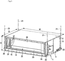
- FIG. 1 is a side view schematically showing a state where an indoor unit of an air conditioner is installed in a ceiling cavity, each of FIG. 2 and
- FIG. 3 is a perspective view of an indoor unit
- FIG. 4 is a cross-sectional view of the indoor unit.
- an indoor unit 1 is installed in, for example, a ceiling cavity of a house/building.
- the ceiling cavity implies a ceiling space 4 defined between a beam 2 of the house/building and a ceiling board 3.
- the indoor unit 1 is a cuboidal flat box-like element, and has a depth dimension D, width dimension W, and thickness dimension H.
- the depth dimension D of the indoor unit 1 is smaller than the width dimension W.
- the thickness dimension H of the indoor unit 1 is sufficiently smaller than the depth dimension D and width dimension W.
- the indoor unit 1 is provided with a housing 5.
- the housing 5 is constituted of, for example, thin metallic plates such as sheet-metal members, and defines the contour of the indoor unit 1.
- the housing 5 includes, as major elements, a top plate 6, a bottom plate 7, a first side plate 8, a second side plate 9, and a partition plate 10.
- the top plate 6 and the bottom plate 7 extend in the horizontal direction, and are opposed to each other with an interval held between them in the thickness direction of the housing 5.
- the bottom plate 7 is divided into two parts of a first plate section 7a and a second plate section 7b.
- a length in the depth direction of the housing 5 is set to about half the depth dimension D of the indoor unit 1.
- the first side plate 8 and the second side plate 9 vertically stand to extend across the top plate 6 and the bottom plate 7, and are opposed to each other with an interval held between them in the width direction of the housing 5.
- the top plate 6, the bottom plate 7, the first side plate 8, and the second side plate 9 define a suction opening 12 at the one end of the housing 5 in the depth direction of the housing 5.
- the suction opening 12 has a long and thin opening shape in the width direction of the housing 5.
- the suction opening 12 is connected to a suction duct 13 shown in FIG. 1 through a filter not shown.
- the top plate 6, the bottom plate 7, the first side plate 8 and the second side plate 9 define a blow-off opening 14 at the other end of the housing 5 in the depth direction of the housing 5.
- the blow-off opening 14 has a long and thin opening shape in the width direction of the housing 5.
- the blow-off opening 14 is connected to a blow-off duct 15 shown in FIG. 1 on the opposite side of the suction opening 12.
- the partition plate 10 partitions the inside of the housing 5 into two chambers of a heat exchanging chamber 16 and a blowing chamber 17.
- the heat exchanging chamber 16 communicates with the blow-off opening 14 of the housing 5.
- the blowing chamber 17 communicates with the suction opening 12 of the housing 5.
- An inner surface of the top plate 6 facing the heat exchanging chamber 16 is covered with, for example, a heat insulating material 18 such as foamed polystyrene.
- a heat insulating material 18 such as foamed polystyrene.
- an inner surface of the second side plate 9 facing the heat exchanging chamber 16 is covered with another heat insulating material not shown.
- a machine chamber 19 is formed at an end part of the heat exchanging chamber 16 adjacent to the second side plate 9.
- the machine chamber 19 is an independent chamber separate from the heat exchanging chamber 16, and refrigeration cycle devices (not shown) such as a drain pump, a refrigerant distributor, and a plurality of refrigerant piping elements are accommodated in the machine chamber 19.
- hanging metal fittings 20 are fixed to four corner parts of the housing 5.
- the hanging metal fittings 20 horizontally protrude from the four corner parts of the housing 5 in four directions of the housing 5, and lower end parts of four hanging bolts 21 downwardly extending from the beam 2 of the house/building are coupled to the hanging metal fittings 20.
- the housing 5 is suspended from the beam 2 of the house/building through the hanging bolts 21.
- a heat exchanger 22 and a drain pan 23 are accommodated in the heat exchanging chamber 16 of the housing 5.
- the heat exchanger 22 extends in the width direction of the housing 5.
- the drain pan 23 is constituted of, for example, a heat insulating material such as foamed polystyrene.
- the drain pan 23 supports the heat exchanger 22 from below in such a manner as to receive drain water dripping from the heat exchanger 22, and surrounds the heat exchanger 22 in cooperation with the heat insulating material 18. Furthermore, an undersurface of the drain pan 23 is covered with the second plate section 7b of the bottom plate 7.
- the heat exchanger 22 of this embodiment is provided with a first heat exchanging unit 24, a second heat exchanging unit 25, and a third heat exchanging unit 26.
- the first to third heat exchanging units 24, 25, and 26 are elements independent of each other, and are combined into a predetermined three-dimensional solid shape.
- Each of the first to third heat exchanging units 24, 25, and 26 is provided with a plurality of long and thin plate-like fins 27, and a plurality of heat-transfer tubes 28 through which the refrigerant flows.
- the fins 27 are arranged with intervals held between them in the width direction of the housing 5.
- the heat-transfer tubes 28 continuously penetrate adjacent the fins 27 to thereby be integrated with the fins 27.
- the first heat exchanging unit 24 is positioned at an upper part of the heat exchanging chamber 16.
- the first heat exchanging unit 24 extends from the partition plate 10 toward the blow-off opening 14 of the housing 5 in the depth direction of the housing 5, and is somewhat downwardly inclined toward the blow-off opening 14.
- the second heat exchanging unit 25 is positioned at a bottom part of the heat exchanging chamber 16, and is separate from the first heat exchanging unit 24 in the thickness direction of the housing 5.
- the second heat exchanging unit 25 extends from the partition plate 10 toward the blow-off opening 14 of the housing 5 in the depth direction of the housing 5, and is somewhat upwardly inclined toward the blow-off opening 14. Accordingly, each of the first heat exchanging unit 24 and the second heat exchanging unit 25 has one end positioned closer to the blow-off opening 14 side than to the partition plate 10 side.
- the third heat exchanging unit 26 is interposed between the one end of the first heat exchanging unit 24 and the one end of the second heat exchanging unit 25.
- the third heat exchanging unit 26 is made to stand in opposition to the partition plate 10, and is upwardly inclined to extend from the one end of the second heat exchanging unit 25 to the one end of the first heat exchanging unit 24 to thereby be made closer to the partition plate 10.
- the first to third heat exchanging units 24, 25, and 26 are combined with each other into a shape spreading toward the partition plate 10 when viewed from the side.
- a blower device 31 is accommodated in the blowing chamber 17.
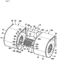
- the blower device 31 includes, as major elements, a fan motor 32, a first fan unit 33a, and a second fan unit 33b.
- the fan motor 32 is provided with a cylindrical motor housing 35 accommodating therein a stator and a rotor, and a rotating shaft 36 coaxially supported by the motor housing 35.
- the motor housing 35 includes a first boss section 37a and a second boss section 37b.
- the first boss section 37a is an example of a first end section, and is protruded from the one end face of the motor housing 35 in the axial direction thereof.
- the second boss section 37b is an example of a second end section, and is protruded from the other end face of the motor housing 35 in the axial direction thereof.
- an annular rubber vibration insulator 38 is coaxially fitted on the outer circumferential surface of each of the first boss section 37a and the second boss section 37b.
- the rotating shaft 36 includes a first shaft section 39a and a second shaft section 39b.
- the first shaft section 39a and the second shaft section 39b are arranged coaxial with each other.
- the first shaft section 39a penetrates the first boss section 37a to outwardly protrude from the motor housing 35.
- the second shaft section 39b penetrates the second boss section 37b to outwardly protrude from the motor housing 35. Accordingly, the first boss section 37a and the second boss section 37b of the motor housing 35 are separate from each other in the axial direction of the rotating shaft 36.
- the first fan unit 33a and the second fan unit 33b are arranged in opposition to each other with an interval held between them, and with the fan motor 32 interposed between them.
- Each of the first fan unit 33a and the second fan unit 33b has a configuration common to them. Accordingly, in this embodiment, the first fan unit 33a will be described as a representative, and constituent elements of the second fan unit 33b are denoted by reference symbols identical to the first fan unit 33a, and their descriptions are omitted.
- the first fan unit 33a is provided with a cylindrical multi-blade fan 40 and a fan case 41.
- the multi-blade fan 40 is coaxially attached to a leading end part of the first shaft section 39a so that the fan 40 can rotate following the rotating shaft 36.
- the multi-blade fan 40 sucks air from the axial direction, and pressurizes the sucked air to discharge the pressurized air from the outer circumferential part thereof in the circumferential direction.
- the fan case 41 is constituted of, for example, thin metallic plates such as sheet-metal members.
- the fan case 41 is provided with a case main body 42 accommodating therein the multi-blade fan 40, and nozzle section 43 provided on the case main body 42.
- the case main body 42 includes an outer circumferential wall 44 curved along the outer circumferential part of the multi-blade fan 40, and a pair of end walls 45a and 45b positioned on both sides of the multi-blade fan 40 in the axial direction thereof.
- Each of the end walls 45a and 45b includes a circular air suction hole 46.
- the first shaft section 39a of the rotating shaft 36 penetrates the air suction hole 46 of the one end wall 45a.
- the nozzle section 43 of the fan case 41 protrudes from the case main body 42 toward the partition plate 10 of the housing 5.
- the multi-blade fan 40 is coaxially attached to the leading end part of the second shaft section 39b of the rotating shaft 36.
- the other items concerning the fan case 41 are identical to the first fan unit 33a.
- the multi-blade fan 40 rotates, air is sucked into the inside of the multi-blade fan 40 through the air suction hole 46.
- the configuration is contrived in such a manner that the air sucked into the multi-blade fan 40 is discharged from the outer circumferential part of the multi-blade fan 40 in the circumferential direction, and is blown from the nozzle section 43 toward the heat exchanger 22.
- the fan motor 32 is installed in the blowing chamber 17 through a motor fixing device 50.
- the motor fixing device 50 includes, as major elements, a motor supporting table 51, a motor base 52, and a pair of motor bands 53a and 53b.
- the motor supporting table 51 is constituted of, for example, thin metallic plates such as sheet-metal members, and is positioned between the first fan unit 33a and the second fan unit 33b.
- the motor supporting table 51 includes a flat supporting surface 55, and a pair of flange sections 56a and 56b.
- the supporting surface 55 is made to vertically stand inside the blowing chamber 17.
- the one flange section 56a protrudes from the one side edge of the motor supporting table 51 toward the first fan unit 33a.
- the other flange section 56b protrudes from the other side edge of the motor supporting table 51 toward the second fan unit 33b.
- the pair of flange sections 56a and 56b are fixed to the partition plate 10 exposed to the blowing chamber 17 through a plurality of fastening members such as bolts and nuts. Accordingly, the motor supporting table 51 is supported by the partition plate 10.
- an attaching piece 57 folded back at right angles in a direction away from the partition plate 10 is formed.
- the attaching piece 57 is coupled to the end wall 45a of the fan case 41 through a plurality of fastening members such as bolts and nuts.
- a bracket 59 is attached to the end wall 45b of the fan case 41.
- the bracket 59 is directly fixed to the partition plate 10 exposed to the blowing chamber 17 through a plurality of fastening members such as bolts and nuts.
- each of the fan case 41 of the first fan unit 33a, and the fan case 41 of the second fan unit 33b is supported by the partition plate 10.
- the motor base 52 of the motor fixing device 50 is constituted of, for example, thin metallic plates such as sheet-metal members.
- the motor base 52 is provided with a base plate section 61 and a pair of supporting sections 62a and 62b.
- the base plate section 61 is a flat rectangular plate-like element, and is fixed to the supporting surface 55 of the motor supporting table 51 at four corners thereof through a plurality of fastening members such as bolts and nuts.
- the one supporting section 62a is folded back at right angles from the one side edge of the base plate section 61 in a direction away from the supporting surface 55.
- the other supporting section 62b is folded back at right angles from the other side edge of the base plate section 61 in a direction away from the supporting surface 55. Accordingly, the pair of supporting sections 62a and 62b are arranged in parallel with each other with an interval held between them in the width direction of the housing 5, and vertically stand inside the blowing chamber 17.
- a motor receiving section 63 is formed at a central part of each of the pair of supporting sections 62a and 62b in the height direction.
- the motor receiving section 63 protrudes in a direction away from the motor supporting table 51.
- the motor receiving section 63 is provided with a concave section 64 curved into an arc-like shape, a first hook section 65 protruding from a tip end of the motor receiving section 63 toward a position above the concave section 64, and a second hook section 66 protruding from the tip end of the motor receiving section 63 toward a position beneath the concave section 64.
- the concave section 64 of the motor receiving section 63 is an element configured to receive the rubber vibration insulator 38 of the fan motor 32.
- the rubber vibration insulator 38 corresponding to the first boss section 37a of the fan motor 32 is fitted into the concave section 64 of the one supporting section 62a
- rubber vibration insulator 38 corresponding to the second boss section 37b is fitted into the concave section 64 of the other supporting section 62b.
- Each of the motor bands 53a and 53b is an example of a fixing member, and has a configuration common to them. Accordingly, in this embodiment, the one motor band 53a will be described as a representative.
- the motor band 53a is constituted of, for example, thin metallic plates such as sheet-metal members, and is divided into two elements of a first band section 68a and a second band section 68b.
- each of the first band section 68a and the second band section 68b is curved into an arc-like shape along the outer circumferential surface of the rubber vibration insulator 38.
- a slit 69 in which the first hook section 65 of the motor receiving section 63 is detachably caught is formed.
- a coupling section 70 horizontally protruding in a direction away from the rubber vibration insulator 38 is formed.
- a slit 71 in which the second hook section 66 of the motor receiving section 63 is detachably caught is formed.
- a coupling section 72 horizontally protruding in a direction away from the rubber vibration insulator 38 is formed.
- the coupling section 70 of the first band section 68a and the coupling section 72 of the second band section 68b are combined with each other through a bolt 73 and nut 74 to be used as fastening members in a state where the coupling section 70 and coupling section 72 are laid one on top of another.
- the motor bands 53a and 53b hold down the rubber vibration insulators 38 in cooperation with the concave sections 64 of the supporting sections 62a and 62b, thereby retaining the rubber vibration insulators 38.
- the fan motor 32 is rubber-mounted on the motor base 52 through the rubber vibration insulators 38, and the rubber vibration insulators 38 are configured to absorb the vibration of the fan motor 32.
- the coupling member 80 is constituted of, for example, thin metallic plates such as sheet-metal members.
- the coupling member 80 is an integrally structured object including a pair of arm sections 81a and 81b and straight bar-like section 82.
- a base end of the one arm section 81a is coupled to the first boss section 37a of the fan motor 32 through the motor band 53a.
- a base end of the other arm section 81b is coupled to the second boss section 37b of the fan motor 32 through the motor band 53b.
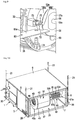
- each of the arm sections 81a and 81b is common to them, and hence the one arm section 81a will be described as a representative. That is, as shown in FIG. 7 through FIG. 9 , the base end of the arm section 81a is jointly coupled to the undersurface of the coupling section 72 of the second band section 68b constituting the motor band 53a through a bolt 73.
- the arm sections 81a and 81b horizontally extend in directions away from the supporting sections 62a and 62b of the motor base 52 with an interval held between them, and the fan motor 32 is interposed between the arm sections 81a and 81b.
- the bar-like section 82 horizontally extends in the axial direction of the rotating shaft 36 of the fan motor 32 across the tip ends of the arm sections 81a and 81b.
- the bar-like section 82 includes a first extension section 82a extended from the one arm section 81a toward the fan case 41 of the first fan unit 33a, and a second extension section 82b extended from the other arm section 81b toward the fan case 41 of the second fan unit 33b.
- a reinforcing flange section 82c upwardly folded back at right angles is formed at the one side edge of the bar-like section 82 in the longitudinal direction of the bar-like section 82 including the first extension section 82a and the second extension section 82b.
- a fixing piece 83a downwardly folded back at right angles is formed.
- a fixing piece 83b downwardly folded back at right angles is formed.
- the one fixing piece 83a of the bar-like section 82 is coupled to the end wall 45a of the fan case 41 of the first fan unit 33a by means of a bolt 84a.
- the other fixing piece 83b of the bar-like section 82 is coupled to the end wall 45a of the fan case 41 of the second fan unit 33b by means of a bolt 84b.
- the bar-like section 82 of the coupling member 80 integrally couples the fan case 41 of the first fan unit 33a and the fan case 41 of the second fan unit 33b to each other on the opposite side of the motor supporting table 51.
- the fan motor 32 is positioned between the bar-like section 82 and the motor base 52, and the fan motor 32 is surrounded by the motor base 52, the arm sections 81a and 81b of the coupling member 80, and the bar-like section 82 of the coupling member 80.
- the arm sections 81a and 81b and bar-like section 82 cooperate with each other to integrally couple the fan motor 32 and the fan case 41 of the first fan unit 33a, and the fan motor 32 and the fan case 41 of the second fan unit 33b together.
- the fan motor 32, the fan case 41 of the first fan unit 33a, and the fan case 41 of the second fan unit 33b are integrally coupled together through the coupling member 80 on the opposite side of the motor supporting table 51.
- the fan case 41 constituted of thin metallic plates by utilizing the coupling member 80.
- the fan case 41 hardly becomes vibrant.
- the coupling member 80 includes the bar-like section 82 extending between the fan case 41 of the first fan unit 33a and the fan case 41 of the second fan unit 33b in the axial direction of the rotating shaft 36 of the fan motor 32.
- the arm sections 81a and 81b of the coupling member 80 are jointly coupled to the motor bands 53a and 53b, respectively by means of the bolts 73 and nuts 74. Accordingly, it is possible to omit dedicated bolts configured to couple the arm sections 81a and 81b of the coupling member 80 to the first boss section 37a and the second boss section 37b of the fan motor 32.
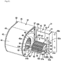
- FIG. 10 and FIG. 11 disclose a second embodiment.
- the second embodiment differs from the first embodiment in the configuration of the blower device 31.
- a blower device 31 is provided with one fan unit 91.
- the configuration of the fan unit 91 is identical to the first fan unit 33a of the first embodiment, and hence constituent elements of the fan unit 91 are denoted by reference symbols identical to the first fan unit 33a, and their descriptions are omitted.
- a rotating shaft 36 of a fan motor 32 penetrates a first end section of a motor housing 35 to protrude to the outside of the motor housing 35.
- a multi-blade fan 40 is coaxially fixed to a protrusion end of the rotating shaft 36. Accordingly, the fan unit 91 is positioned on one side of the fan motor 32 in an axial direction of the fan motor 32.
- a coupling member 80 configured to couple the fan motor 32 and the fan case 41 of the fan unit 91 to each other, only one end part of a bar-like section 82 extending across the arm sections 81a and 81b is extended toward the fan unit 91, and a fixing piece 92 is formed at one end part of the bar-like section 82.
- the fixing piece 92 is coupled to an end wall 45a of the fan case 41 through a bolt 93.
- housing 22 ⁇ heat exchanger, 31 ⁇ blower device, 32 ⁇ fan motor, 36 ⁇ rotating shaft, 37a ⁇ first end section (first boss section), 37b ⁇ second end section (second boss section), 40 ⁇ fan (multi-blade fan), 41 ⁇ fan case, 80 ⁇ coupling member, 81a, 81b ⁇ arm section, and 82 ⁇ bar-like section.
Landscapes
- Engineering & Computer Science (AREA)
- Mechanical Engineering (AREA)
- General Engineering & Computer Science (AREA)
- Chemical & Material Sciences (AREA)
- Combustion & Propulsion (AREA)
- Physics & Mathematics (AREA)
- Thermal Sciences (AREA)
- Structures Of Non-Positive Displacement Pumps (AREA)
- Devices For Blowing Cold Air, Devices For Blowing Warm Air, And Means For Preventing Water Condensation In Air Conditioning Units (AREA)
- Air-Conditioning Room Units, And Self-Contained Units In General (AREA)
Claims (3)
- Klimaanlage aufweisend:einen Wärmetauscher (22), der so konfiguriert ist, dass er einen Wärmeaustausch zwischen einem Kältemittel und Luft durchführt;eine Gebläsevorrichtung (31), die so konfiguriert ist, dass sie dem Wärmetauscher (22) Luft zuführt; undein Gehäuse (5, 35), in dem der Wärmetauscher (22) und die Gebläsevorrichtung (31) untergebracht sind, wobeidie Gebläsevorrichtung (31) umfassteinen Gebläsemotor (32) mit einer Drehwelle (36) und einem ersten Endabschnitt (37a) und einem zweiten Endabschnitt (37b), die in einer axialen Richtung der Drehwelle (36) voneinander beabstandet sind,ein Gebläse (40), das koaxial an der Drehwelle (36) des Gebläsemotors (32) befestigt und so konfiguriert ist, dass es sich mit der Drehwelle (36) dreht,ein Gebläsegehäuse (41), in dem das Gebläse (40) untergebracht ist und das so konfiguriert ist, dass es Luft, die aus dem Gebläse (40) herausbläst, zum Wärmetauscher (22) leitet, undein Kupplungselement (80) mit einem Paar Armabschnitten (81a und 81b), die jeweils mit dem ersten Endabschnitt (37a) und dem zweiten Endabschnitt (37b) des Gebläsemotors (32) gekoppelt sind, und einem stabförmigen Abschnitt (82), der sich in der axialen Richtung der Drehwelle (36) über die Armabschnitte (81a und 81b) erstreckt und mit dem Gebläsegehäuse (41) gekoppelt ist, undder Gebläsemotor (32) und das Gebläsegehäuse (41) über das Kupplungselement (80) einstückig miteinander gekoppelt sind,dadurch gekennzeichnet, dassdas Gehäuse (5) eine Wärmetauscherkammer (16), in der der Wärmetauscher (22) untergebracht ist, eine Gebläsekammer (17), in der die Gebläsevorrichtung (31) untergebracht ist, und eine Trennplatte (10), die die Wärmetauscherkammer (16) und die Gebläsekammer (17) voneinander trennt, und eine Motorbefestigungsvorrichtung (50), die konfiguriert, den Gebläsemotor (32) in der Gebläsekammer (17) zu installieren, umfasst ,wobeidie Motorbefestigungsvorrichtung (50) einen Motorträgertisch (51), der in der Gebläsekammer (17) angeordnet ist, eine Motorbasis (52), die an dem Motorträgertisch (51) angebracht ist und ein Paar von Trägerabschnitten (62a und 62b), die jeweils so konfiguriert sind, dass sie den ersten Endabschnitt (37a) und den zweiten Endabschnitt (37b) des Gebläsemotors (32) aufnehmen, und ein Paar von Befestigungsgliedern enthält, die jeweils so konfiguriert sind, dass sie den ersten Endabschnitt (37a) und den zweiten Endabschnitt (37b) des Motors in Zusammenwirkung mit den Trägerabschnitten (62a und 62b) der Motorbasis (52) niederhalten, um dadurch die Endabschnitte zu halten, unddie Armabschnitte (81a und 81b) des Kupplungselements (80) mit den Befestigungsgliedern gekoppelt sind.
- Klimagerät nach Anspruch 1, wobei
jedes der Befestigungsglieder in ein Paar von Bandabschnitten unterteilt ist, ein Ende jedes der Bandabschnitte (68a und 68b) mit jedem der Trägerabschnitte (62a und 62b) der Motorbasis (52) in Eingriff ist und die anderen Enden der Bandabschnitte über Befestigungselemente miteinander gekoppelt sind. - Klimagerät nach Anspruch 2, wobei
jeder der Armabschnitte (81a und 81b) des Kopplungselements (80) gemeinsam mit jedem der Befestigungsglieder durch die Befestigungselemente gekoppelt ist.
Applications Claiming Priority (1)
| Application Number | Priority Date | Filing Date | Title |
|---|---|---|---|
| PCT/JP2016/057018 WO2017154081A1 (ja) | 2016-03-07 | 2016-03-07 | 空気調和機および送風装置 |
Publications (3)
| Publication Number | Publication Date |
|---|---|
| EP3428548A1 EP3428548A1 (de) | 2019-01-16 |
| EP3428548A4 EP3428548A4 (de) | 2019-10-16 |
| EP3428548B1 true EP3428548B1 (de) | 2021-10-20 |
Family
ID=59789085
Family Applications (1)
| Application Number | Title | Priority Date | Filing Date |
|---|---|---|---|
| EP16893413.1A Active EP3428548B1 (de) | 2016-03-07 | 2016-03-07 | Klimaanlage und gebläsevorrichtung |
Country Status (5)
| Country | Link |
|---|---|
| US (1) | US10962238B2 (de) |
| EP (1) | EP3428548B1 (de) |
| JP (1) | JP6572382B2 (de) |
| AU (1) | AU2016396507B2 (de) |
| WO (1) | WO2017154081A1 (de) |
Families Citing this family (10)
| Publication number | Priority date | Publication date | Assignee | Title |
|---|---|---|---|---|
| US10753627B1 (en) * | 2005-07-13 | 2020-08-25 | Qc Manufacturing, Inc. | Air cooling system for a building structure |
| CN110726177B (zh) * | 2019-11-08 | 2023-07-21 | 海信空调有限公司 | 空调室内机 |
| CN110701679B (zh) * | 2019-11-08 | 2023-07-25 | 海信空调有限公司 | 空调室内机 |
| CN110701680B (zh) * | 2019-11-08 | 2023-07-21 | 海信空调有限公司 | 空调室内机 |
| AU2020386528B2 (en) | 2019-11-22 | 2023-06-01 | Qc Manufacturing, Inc. | Fresh air cooling and ventilating system |
| CN111102651B (zh) * | 2019-12-26 | 2020-12-25 | 珠海格力电器股份有限公司 | 分体式外壳的风管机 |
| CN112378064B (zh) * | 2020-11-16 | 2021-09-28 | 珠海格力电器股份有限公司 | 风道结构、控制方法及空调柜机 |
| CN112556060B (zh) * | 2020-12-14 | 2021-12-03 | 珠海格力电器股份有限公司 | 新风机 |
| CN114771353B (zh) * | 2022-06-21 | 2022-10-14 | 徐州市恒源电器有限公司 | 一种便于动态散热的新能源汽车电源 |
| KR20240155303A (ko) * | 2022-12-12 | 2024-10-28 | 지디 미디어 히팅 엔드 벤틸레이팅 이큅먼트 코 엘티디 | 에어컨 실내기 및 에어컨 |
Family Cites Families (20)
| Publication number | Priority date | Publication date | Assignee | Title |
|---|---|---|---|---|
| US2899803A (en) * | 1959-08-18 | Air conditioning apparatus | ||
| US3491550A (en) * | 1968-06-27 | 1970-01-27 | Trane Co | Room cooler |
| JPS5816399U (ja) * | 1981-07-24 | 1983-02-01 | 株式会社東芝 | フアン取付装置 |
| US4597269A (en) * | 1984-09-20 | 1986-07-01 | Kim Il Y | Plastic pan having a refrigerator support |
| US4823558A (en) * | 1988-06-28 | 1989-04-25 | Il Yoo Kim | Plastic pan assembly for use in air conditioners and refrigerators |
| US4974421A (en) * | 1989-11-22 | 1990-12-04 | Permanent Solution Industries, Inc. | Plastic pan assembly having an U-shaped supporting bracket for use in air conditioners and refrigerators |
| US4986087A (en) * | 1989-12-01 | 1991-01-22 | Sullivan John T | Fan coil unit |
| US5105630A (en) * | 1991-07-02 | 1992-04-21 | Kim Chang H | Air conditioning system containing a plastic drain pan |
| US5152154A (en) * | 1991-11-12 | 1992-10-06 | Sullivan John T | Fan coil unit |
| JP3376712B2 (ja) * | 1994-09-27 | 2003-02-10 | ダイキン工業株式会社 | 空気調和機のモータ取付構造 |
| US20040093885A1 (en) * | 2002-11-11 | 2004-05-20 | Koji Ito | Vehicle air conditioner with main blower and sub-blower |
| JP4266157B2 (ja) * | 2003-11-28 | 2009-05-20 | 東芝キヤリア株式会社 | 空気調和装置 |
| KR101313567B1 (ko) * | 2007-02-23 | 2013-10-01 | 한라비스테온공조 주식회사 | 차량용 송풍기 모터의 냉각장치 |
| JP2010127533A (ja) * | 2008-11-27 | 2010-06-10 | Daikin Ind Ltd | 空気調和装置及び空気調和装置におけるファンユニットの設置方法 |
| JP2011033282A (ja) * | 2009-08-03 | 2011-02-17 | Mitsubishi Electric Corp | 空気調和装置 |
| JP5720918B2 (ja) * | 2009-12-11 | 2015-05-20 | 株式会社富士通ゼネラル | ダクト型空気調和機 |
| JP2012100394A (ja) * | 2010-10-29 | 2012-05-24 | Fujitsu General Ltd | モータ取付装置 |
| JP2012191734A (ja) * | 2011-03-10 | 2012-10-04 | Daikin Ind Ltd | 電動機 |
| JP2013024444A (ja) * | 2011-07-19 | 2013-02-04 | Hitachi Appliances Inc | 空気調和機 |
| KR20130043983A (ko) * | 2011-10-21 | 2013-05-02 | 엘지전자 주식회사 | 공기조화기 |
-
2016
- 2016-03-07 JP JP2018503874A patent/JP6572382B2/ja active Active
- 2016-03-07 AU AU2016396507A patent/AU2016396507B2/en active Active
- 2016-03-07 WO PCT/JP2016/057018 patent/WO2017154081A1/ja not_active Ceased
- 2016-03-07 EP EP16893413.1A patent/EP3428548B1/de active Active
-
2018
- 2018-09-06 US US16/123,424 patent/US10962238B2/en active Active
Also Published As
| Publication number | Publication date |
|---|---|
| WO2017154081A1 (ja) | 2017-09-14 |
| AU2016396507B2 (en) | 2020-03-19 |
| EP3428548A1 (de) | 2019-01-16 |
| AU2016396507A1 (en) | 2018-09-27 |
| JP6572382B2 (ja) | 2019-09-11 |
| US20190003728A1 (en) | 2019-01-03 |
| JPWO2017154081A1 (ja) | 2018-08-09 |
| US10962238B2 (en) | 2021-03-30 |
| EP3428548A4 (de) | 2019-10-16 |
Similar Documents
| Publication | Publication Date | Title |
|---|---|---|
| EP3428548B1 (de) | Klimaanlage und gebläsevorrichtung | |
| EP2980494B1 (de) | Ausseneinheit für klimaanlagenvorrichtung | |
| EP1873461A1 (de) | In raumdecke eingebaute klimaanlage | |
| JP6134855B2 (ja) | 空気調和機 | |
| ES2790662T3 (es) | Unidad interior de acondicionador de aire | |
| JP6458984B2 (ja) | 天井埋込型空気調和機 | |
| CN101688735B (zh) | 具有通风组件的制冷装置 | |
| US9249984B2 (en) | Base pan | |
| KR102203437B1 (ko) | 공기조화기의 실내기 | |
| EP3091304B1 (de) | Klimaanlage | |
| CN106123153B (zh) | 一种空调室外机及空调 | |
| JP2013204874A (ja) | 空気調和機 | |
| EP2336574B1 (de) | Schalldichtbehälter für einen Radiallüfter | |
| JP5849795B2 (ja) | 空気調和機 | |
| JP4884781B2 (ja) | 空気調和装置用キャビネット及びこれを用いた空気調和装置 | |
| JP2006003011A (ja) | 高所設置型空気調和機の天板構造 | |
| JP2017172935A (ja) | 空気調和機 | |
| JP5891408B2 (ja) | 空気調和装置の室外ユニット | |
| CN203454290U (zh) | 冷冻装置的室外机 | |
| CN110402353A (zh) | 用于热泵或空调的热交换单元 | |
| JP2011257068A (ja) | 空気調和装置用キャビネット及びこれを用いた空気調和装置 | |
| CN100467960C (zh) | 空调装置 | |
| WO2017164044A1 (ja) | 空気調和機および吊金具 | |
| WO2024157650A1 (ja) | 室外機用保護部材および冷凍サイクル装置 | |
| CN111829068A (zh) | 壁挂式空调室内机及空调器 |
Legal Events
| Date | Code | Title | Description |
|---|---|---|---|
| STAA | Information on the status of an ep patent application or granted ep patent |
Free format text: STATUS: THE INTERNATIONAL PUBLICATION HAS BEEN MADE |
|
| PUAI | Public reference made under article 153(3) epc to a published international application that has entered the european phase |
Free format text: ORIGINAL CODE: 0009012 |
|
| STAA | Information on the status of an ep patent application or granted ep patent |
Free format text: STATUS: REQUEST FOR EXAMINATION WAS MADE |
|
| 17P | Request for examination filed |
Effective date: 20180905 |
|
| AK | Designated contracting states |
Kind code of ref document: A1 Designated state(s): AL AT BE BG CH CY CZ DE DK EE ES FI FR GB GR HR HU IE IS IT LI LT LU LV MC MK MT NL NO PL PT RO RS SE SI SK SM TR |
|
| AX | Request for extension of the european patent |
Extension state: BA ME |
|
| DAV | Request for validation of the european patent (deleted) | ||
| DAX | Request for extension of the european patent (deleted) | ||
| A4 | Supplementary search report drawn up and despatched |
Effective date: 20190918 |
|
| RIC1 | Information provided on ipc code assigned before grant |
Ipc: F04D 29/00 20060101ALI20190912BHEP Ipc: F24F 1/0033 20190101ALI20190912BHEP Ipc: F24F 13/20 20060101ALI20190912BHEP Ipc: F24F 13/24 20060101ALI20190912BHEP Ipc: F24F 1/0022 20190101ALI20190912BHEP Ipc: F24F 1/00 20190101AFI20190912BHEP |
|
| GRAP | Despatch of communication of intention to grant a patent |
Free format text: ORIGINAL CODE: EPIDOSNIGR1 |
|
| STAA | Information on the status of an ep patent application or granted ep patent |
Free format text: STATUS: GRANT OF PATENT IS INTENDED |
|
| RIC1 | Information provided on ipc code assigned before grant |
Ipc: F04D 25/16 20060101ALI20210423BHEP Ipc: F04D 29/42 20060101ALI20210423BHEP Ipc: F04D 29/66 20060101ALI20210423BHEP Ipc: F04D 29/054 20060101ALI20210423BHEP Ipc: F24F 1/0033 20190101ALI20210423BHEP Ipc: F24F 1/0022 20190101ALI20210423BHEP Ipc: F24F 13/24 20060101ALI20210423BHEP Ipc: F24F 13/20 20060101ALI20210423BHEP Ipc: F24F 1/00 20190101AFI20210423BHEP |
|
| INTG | Intention to grant announced |
Effective date: 20210519 |
|
| GRAS | Grant fee paid |
Free format text: ORIGINAL CODE: EPIDOSNIGR3 |
|
| GRAA | (expected) grant |
Free format text: ORIGINAL CODE: 0009210 |
|
| STAA | Information on the status of an ep patent application or granted ep patent |
Free format text: STATUS: THE PATENT HAS BEEN GRANTED |
|
| AK | Designated contracting states |
Kind code of ref document: B1 Designated state(s): AL AT BE BG CH CY CZ DE DK EE ES FI FR GB GR HR HU IE IS IT LI LT LU LV MC MK MT NL NO PL PT RO RS SE SI SK SM TR |
|
| REG | Reference to a national code |
Ref country code: GB Ref legal event code: FG4D |
|
| REG | Reference to a national code |
Ref country code: CH Ref legal event code: EP |
|
| REG | Reference to a national code |
Ref country code: IE Ref legal event code: FG4D |
|
| REG | Reference to a national code |
Ref country code: DE Ref legal event code: R096 Ref document number: 602016065287 Country of ref document: DE |
|
| REG | Reference to a national code |
Ref country code: AT Ref legal event code: REF Ref document number: 1440252 Country of ref document: AT Kind code of ref document: T Effective date: 20211115 |
|
| REG | Reference to a national code |
Ref country code: LT Ref legal event code: MG9D |
|
| REG | Reference to a national code |
Ref country code: NL Ref legal event code: MP Effective date: 20211020 |
|
| REG | Reference to a national code |
Ref country code: AT Ref legal event code: MK05 Ref document number: 1440252 Country of ref document: AT Kind code of ref document: T Effective date: 20211020 |
|
| PG25 | Lapsed in a contracting state [announced via postgrant information from national office to epo] |
Ref country code: RS Free format text: LAPSE BECAUSE OF FAILURE TO SUBMIT A TRANSLATION OF THE DESCRIPTION OR TO PAY THE FEE WITHIN THE PRESCRIBED TIME-LIMIT Effective date: 20211020 Ref country code: LT Free format text: LAPSE BECAUSE OF FAILURE TO SUBMIT A TRANSLATION OF THE DESCRIPTION OR TO PAY THE FEE WITHIN THE PRESCRIBED TIME-LIMIT Effective date: 20211020 Ref country code: FI Free format text: LAPSE BECAUSE OF FAILURE TO SUBMIT A TRANSLATION OF THE DESCRIPTION OR TO PAY THE FEE WITHIN THE PRESCRIBED TIME-LIMIT Effective date: 20211020 Ref country code: BG Free format text: LAPSE BECAUSE OF FAILURE TO SUBMIT A TRANSLATION OF THE DESCRIPTION OR TO PAY THE FEE WITHIN THE PRESCRIBED TIME-LIMIT Effective date: 20220120 Ref country code: AT Free format text: LAPSE BECAUSE OF FAILURE TO SUBMIT A TRANSLATION OF THE DESCRIPTION OR TO PAY THE FEE WITHIN THE PRESCRIBED TIME-LIMIT Effective date: 20211020 |
|
| PG25 | Lapsed in a contracting state [announced via postgrant information from national office to epo] |
Ref country code: IS Free format text: LAPSE BECAUSE OF FAILURE TO SUBMIT A TRANSLATION OF THE DESCRIPTION OR TO PAY THE FEE WITHIN THE PRESCRIBED TIME-LIMIT Effective date: 20220220 Ref country code: SE Free format text: LAPSE BECAUSE OF FAILURE TO SUBMIT A TRANSLATION OF THE DESCRIPTION OR TO PAY THE FEE WITHIN THE PRESCRIBED TIME-LIMIT Effective date: 20211020 Ref country code: PT Free format text: LAPSE BECAUSE OF FAILURE TO SUBMIT A TRANSLATION OF THE DESCRIPTION OR TO PAY THE FEE WITHIN THE PRESCRIBED TIME-LIMIT Effective date: 20220221 Ref country code: PL Free format text: LAPSE BECAUSE OF FAILURE TO SUBMIT A TRANSLATION OF THE DESCRIPTION OR TO PAY THE FEE WITHIN THE PRESCRIBED TIME-LIMIT Effective date: 20211020 Ref country code: NO Free format text: LAPSE BECAUSE OF FAILURE TO SUBMIT A TRANSLATION OF THE DESCRIPTION OR TO PAY THE FEE WITHIN THE PRESCRIBED TIME-LIMIT Effective date: 20220120 Ref country code: NL Free format text: LAPSE BECAUSE OF FAILURE TO SUBMIT A TRANSLATION OF THE DESCRIPTION OR TO PAY THE FEE WITHIN THE PRESCRIBED TIME-LIMIT Effective date: 20211020 Ref country code: LV Free format text: LAPSE BECAUSE OF FAILURE TO SUBMIT A TRANSLATION OF THE DESCRIPTION OR TO PAY THE FEE WITHIN THE PRESCRIBED TIME-LIMIT Effective date: 20211020 Ref country code: HR Free format text: LAPSE BECAUSE OF FAILURE TO SUBMIT A TRANSLATION OF THE DESCRIPTION OR TO PAY THE FEE WITHIN THE PRESCRIBED TIME-LIMIT Effective date: 20211020 Ref country code: GR Free format text: LAPSE BECAUSE OF FAILURE TO SUBMIT A TRANSLATION OF THE DESCRIPTION OR TO PAY THE FEE WITHIN THE PRESCRIBED TIME-LIMIT Effective date: 20220121 Ref country code: ES Free format text: LAPSE BECAUSE OF FAILURE TO SUBMIT A TRANSLATION OF THE DESCRIPTION OR TO PAY THE FEE WITHIN THE PRESCRIBED TIME-LIMIT Effective date: 20211020 |
|
| REG | Reference to a national code |
Ref country code: DE Ref legal event code: R097 Ref document number: 602016065287 Country of ref document: DE |
|
| PG25 | Lapsed in a contracting state [announced via postgrant information from national office to epo] |
Ref country code: SM Free format text: LAPSE BECAUSE OF FAILURE TO SUBMIT A TRANSLATION OF THE DESCRIPTION OR TO PAY THE FEE WITHIN THE PRESCRIBED TIME-LIMIT Effective date: 20211020 Ref country code: SK Free format text: LAPSE BECAUSE OF FAILURE TO SUBMIT A TRANSLATION OF THE DESCRIPTION OR TO PAY THE FEE WITHIN THE PRESCRIBED TIME-LIMIT Effective date: 20211020 Ref country code: RO Free format text: LAPSE BECAUSE OF FAILURE TO SUBMIT A TRANSLATION OF THE DESCRIPTION OR TO PAY THE FEE WITHIN THE PRESCRIBED TIME-LIMIT Effective date: 20211020 Ref country code: EE Free format text: LAPSE BECAUSE OF FAILURE TO SUBMIT A TRANSLATION OF THE DESCRIPTION OR TO PAY THE FEE WITHIN THE PRESCRIBED TIME-LIMIT Effective date: 20211020 Ref country code: DK Free format text: LAPSE BECAUSE OF FAILURE TO SUBMIT A TRANSLATION OF THE DESCRIPTION OR TO PAY THE FEE WITHIN THE PRESCRIBED TIME-LIMIT Effective date: 20211020 Ref country code: CZ Free format text: LAPSE BECAUSE OF FAILURE TO SUBMIT A TRANSLATION OF THE DESCRIPTION OR TO PAY THE FEE WITHIN THE PRESCRIBED TIME-LIMIT Effective date: 20211020 |
|
| PLBE | No opposition filed within time limit |
Free format text: ORIGINAL CODE: 0009261 |
|
| STAA | Information on the status of an ep patent application or granted ep patent |
Free format text: STATUS: NO OPPOSITION FILED WITHIN TIME LIMIT |
|
| 26N | No opposition filed |
Effective date: 20220721 |
|
| PG25 | Lapsed in a contracting state [announced via postgrant information from national office to epo] |
Ref country code: MC Free format text: LAPSE BECAUSE OF FAILURE TO SUBMIT A TRANSLATION OF THE DESCRIPTION OR TO PAY THE FEE WITHIN THE PRESCRIBED TIME-LIMIT Effective date: 20211020 Ref country code: AL Free format text: LAPSE BECAUSE OF FAILURE TO SUBMIT A TRANSLATION OF THE DESCRIPTION OR TO PAY THE FEE WITHIN THE PRESCRIBED TIME-LIMIT Effective date: 20211020 |
|
| REG | Reference to a national code |
Ref country code: CH Ref legal event code: PL |
|
| PG25 | Lapsed in a contracting state [announced via postgrant information from national office to epo] |
Ref country code: SI Free format text: LAPSE BECAUSE OF FAILURE TO SUBMIT A TRANSLATION OF THE DESCRIPTION OR TO PAY THE FEE WITHIN THE PRESCRIBED TIME-LIMIT Effective date: 20211020 |
|
| REG | Reference to a national code |
Ref country code: BE Ref legal event code: MM Effective date: 20220331 |
|
| PG25 | Lapsed in a contracting state [announced via postgrant information from national office to epo] |
Ref country code: LU Free format text: LAPSE BECAUSE OF NON-PAYMENT OF DUE FEES Effective date: 20220307 Ref country code: LI Free format text: LAPSE BECAUSE OF NON-PAYMENT OF DUE FEES Effective date: 20220331 Ref country code: IE Free format text: LAPSE BECAUSE OF NON-PAYMENT OF DUE FEES Effective date: 20220307 Ref country code: CH Free format text: LAPSE BECAUSE OF NON-PAYMENT OF DUE FEES Effective date: 20220331 |
|
| PG25 | Lapsed in a contracting state [announced via postgrant information from national office to epo] |
Ref country code: BE Free format text: LAPSE BECAUSE OF NON-PAYMENT OF DUE FEES Effective date: 20220331 |
|
| PG25 | Lapsed in a contracting state [announced via postgrant information from national office to epo] |
Ref country code: IT Free format text: LAPSE BECAUSE OF FAILURE TO SUBMIT A TRANSLATION OF THE DESCRIPTION OR TO PAY THE FEE WITHIN THE PRESCRIBED TIME-LIMIT Effective date: 20211020 |
|
| PG25 | Lapsed in a contracting state [announced via postgrant information from national office to epo] |
Ref country code: HU Free format text: LAPSE BECAUSE OF FAILURE TO SUBMIT A TRANSLATION OF THE DESCRIPTION OR TO PAY THE FEE WITHIN THE PRESCRIBED TIME-LIMIT; INVALID AB INITIO Effective date: 20160307 |
|
| PG25 | Lapsed in a contracting state [announced via postgrant information from national office to epo] |
Ref country code: MK Free format text: LAPSE BECAUSE OF FAILURE TO SUBMIT A TRANSLATION OF THE DESCRIPTION OR TO PAY THE FEE WITHIN THE PRESCRIBED TIME-LIMIT Effective date: 20211020 Ref country code: CY Free format text: LAPSE BECAUSE OF FAILURE TO SUBMIT A TRANSLATION OF THE DESCRIPTION OR TO PAY THE FEE WITHIN THE PRESCRIBED TIME-LIMIT Effective date: 20211020 |
|
| PG25 | Lapsed in a contracting state [announced via postgrant information from national office to epo] |
Ref country code: MT Free format text: LAPSE BECAUSE OF FAILURE TO SUBMIT A TRANSLATION OF THE DESCRIPTION OR TO PAY THE FEE WITHIN THE PRESCRIBED TIME-LIMIT Effective date: 20211020 |
|
| PG25 | Lapsed in a contracting state [announced via postgrant information from national office to epo] |
Ref country code: TR Free format text: LAPSE BECAUSE OF FAILURE TO SUBMIT A TRANSLATION OF THE DESCRIPTION OR TO PAY THE FEE WITHIN THE PRESCRIBED TIME-LIMIT Effective date: 20211020 |
|
| PGFP | Annual fee paid to national office [announced via postgrant information from national office to epo] |
Ref country code: GB Payment date: 20260219 Year of fee payment: 11 |
|
| PGFP | Annual fee paid to national office [announced via postgrant information from national office to epo] |
Ref country code: DE Payment date: 20260219 Year of fee payment: 11 |
|
| PGFP | Annual fee paid to national office [announced via postgrant information from national office to epo] |
Ref country code: FR Payment date: 20260220 Year of fee payment: 11 |