EP2336574B1 - Schalldichtbehälter für einen Radiallüfter - Google Patents
Schalldichtbehälter für einen Radiallüfter Download PDFInfo
- Publication number
- EP2336574B1 EP2336574B1 EP20100015815 EP10015815A EP2336574B1 EP 2336574 B1 EP2336574 B1 EP 2336574B1 EP 20100015815 EP20100015815 EP 20100015815 EP 10015815 A EP10015815 A EP 10015815A EP 2336574 B1 EP2336574 B1 EP 2336574B1
- Authority
- EP
- European Patent Office
- Prior art keywords
- scroll
- motor
- scroll case
- covering
- box according
- Prior art date
- Legal status (The legal status is an assumption and is not a legal conclusion. Google has not performed a legal analysis and makes no representation as to the accuracy of the status listed.)
- Not-in-force
Links
- 238000005192 partition Methods 0.000 claims description 15
- 238000001816 cooling Methods 0.000 claims description 3
- 238000000926 separation method Methods 0.000 claims 1
- 230000005540 biological transmission Effects 0.000 description 3
- 238000007599 discharging Methods 0.000 description 3
- 238000004519 manufacturing process Methods 0.000 description 3
- 238000009434 installation Methods 0.000 description 2
- 230000015572 biosynthetic process Effects 0.000 description 1
- 238000010586 diagram Methods 0.000 description 1
- 238000001035 drying Methods 0.000 description 1
- 230000000694 effects Effects 0.000 description 1
- 230000002349 favourable effect Effects 0.000 description 1
- 239000000126 substance Substances 0.000 description 1
- 238000003786 synthesis reaction Methods 0.000 description 1
- 238000011144 upstream manufacturing Methods 0.000 description 1
- 238000003466 welding Methods 0.000 description 1
Images







Classifications
-
- F—MECHANICAL ENGINEERING; LIGHTING; HEATING; WEAPONS; BLASTING
- F04—POSITIVE - DISPLACEMENT MACHINES FOR LIQUIDS; PUMPS FOR LIQUIDS OR ELASTIC FLUIDS
- F04D—NON-POSITIVE-DISPLACEMENT PUMPS
- F04D29/00—Details, component parts, or accessories
- F04D29/66—Combating cavitation, whirls, noise, vibration or the like; Balancing
- F04D29/661—Combating cavitation, whirls, noise, vibration or the like; Balancing especially adapted for elastic fluid pumps
- F04D29/663—Sound attenuation
- F04D29/664—Sound attenuation by means of sound absorbing material
-
- F—MECHANICAL ENGINEERING; LIGHTING; HEATING; WEAPONS; BLASTING
- F04—POSITIVE - DISPLACEMENT MACHINES FOR LIQUIDS; PUMPS FOR LIQUIDS OR ELASTIC FLUIDS
- F04D—NON-POSITIVE-DISPLACEMENT PUMPS
- F04D29/00—Details, component parts, or accessories
- F04D29/40—Casings; Connections of working fluid
- F04D29/42—Casings; Connections of working fluid for radial or helico-centrifugal pumps
- F04D29/4206—Casings; Connections of working fluid for radial or helico-centrifugal pumps especially adapted for elastic fluid pumps
- F04D29/4226—Fan casings
-
- F—MECHANICAL ENGINEERING; LIGHTING; HEATING; WEAPONS; BLASTING
- F04—POSITIVE - DISPLACEMENT MACHINES FOR LIQUIDS; PUMPS FOR LIQUIDS OR ELASTIC FLUIDS
- F04D—NON-POSITIVE-DISPLACEMENT PUMPS
- F04D29/00—Details, component parts, or accessories
- F04D29/60—Mounting; Assembling; Disassembling
- F04D29/62—Mounting; Assembling; Disassembling of radial or helico-centrifugal pumps
- F04D29/624—Mounting; Assembling; Disassembling of radial or helico-centrifugal pumps especially adapted for elastic fluid pumps
- F04D29/626—Mounting or removal of fans
-
- F—MECHANICAL ENGINEERING; LIGHTING; HEATING; WEAPONS; BLASTING
- F24—HEATING; RANGES; VENTILATING
- F24F—AIR-CONDITIONING; AIR-HUMIDIFICATION; VENTILATION; USE OF AIR CURRENTS FOR SCREENING
- F24F13/00—Details common to, or for air-conditioning, air-humidification, ventilation or use of air currents for screening
- F24F13/24—Means for preventing or suppressing noise
-
- F—MECHANICAL ENGINEERING; LIGHTING; HEATING; WEAPONS; BLASTING
- F24—HEATING; RANGES; VENTILATING
- F24F—AIR-CONDITIONING; AIR-HUMIDIFICATION; VENTILATION; USE OF AIR CURRENTS FOR SCREENING
- F24F13/00—Details common to, or for air-conditioning, air-humidification, ventilation or use of air currents for screening
- F24F13/20—Casings or covers
- F24F2013/205—Mounting a ventilator fan therein
Definitions
- the present invention relates to a soundroof box for a centrifugal fan.
- a centrifugal fan consists of a scroll, of a wheel arranged Inside the scroll, and of an electric motor for driving the wheel directly or through a transmission. Air is intaked by the effect generated by the wheel that is rotated by the electric motor, is therefore centrifuged towards the outside by the wheel, and the scroll, the profile of which is so shaped as a wound nozzle, collects the air discharged from the periphery of the wheel and send it the outlet mouth with a greater pressure and a predetermined speed, with the the aim of developing industrial processes such as drying, transport of materials and other.
- the source of noise of the fan can be divided into:
- known soundproof boxes for industrial fans consist of a case adapted to contain the fan, which is formed by sheet panels that are covered inside by a soundproof material.
- the Inlet mouth can be connected to a pipe for intaking air fom a zone far from the fan, and the outlet mouth can be connected to an other pipe or to a circuit for discharging air in an other zone far from the fan; or, the inlet mouth can be free (such as in fans applied to burners), the fan inletting air from the environment and discharging it in a circuit (in this case the intaked air can be or not filtered by suitable filters); or, the outlet mouth can be free, the fan sucking air from a circuit and discharging it In the environment (such as in the case of industrial vacuum cleaners).
- Another parameter at stake consists of the arrangement of the scroll.
- UNI specifications recognize eight different angular orientations of the scroll with respect to the axis of rotation of the wheel, that are spaced 45° one to the other.
- the scroll can be overturned of 180° in order to be fitted to a right-handed or a left-handed wheel.
- a support structure Is provided, so-called chair, that on the one hand acts as a base for the electric motor and, on the other hand, allows the scroll to be fixed.
- chair that on the one hand acts as a base for the electric motor and, on the other hand, allows the scroll to be fixed.
- other configurations lacking in the chair exist, in which the scroll is fixed to a different support, or configurations in which the chair supports a shaft connected to the wheel, which shaft receives the motion through a transmission from an electric motor arranged close to the chair.
- the diameter and the width of the scroll are the diameter and the width of the scroll, as a function of the flow rate and pressure required for the fan.
- the flow rate depends on the duty to be carried out by the fan.
- the pressure depends on the length and configuration of the pipes connected to the inlet and/or outlet mouths, as well as on the kind of duty required.
- Each fan has a wheel diameter that, combined with the speed of rotation, generates a predetermined pressure; moreover, the width of the scroll is strictly linked with the flow rater. This means that two fans having the same diameter, one of which is wide the double of the other, indicatively have the same pressure at the outlet mouth, but the one has a flow rate double with respect to the other.
- US-4 279 325-A discloses a soundproof box comprising a support frame that supports outside a motor of the fan and holds up a scroll of the fan, a parallelepiped soundproof scroll case containing the scroll and comprising a pair of end walls as well as a plurality of side walls mounted between the end walls, and connecting means that allow the scroll case to be mounted on the support frame, which are positioned between the support frame and at least one of the end walls of the scroll case.
- An object of the invention is that of proposing a soundproof box that is so shaped as to allow a high structural modularity to be achieved, and that allow therefore a mass production by industry to be achieved.
- the scroll case can be rotated as a result of the various orientations of the fan, and it can be arranged both in the right-handed and in the left-handed configuration, while the sidewalls can be replaced in order to allow different widths of the scroll to be fitted and in order to allow filters, partition walls and possible further fittings to be installed.
- the various members of the box can be manufactured as a series of parts that can be combined in several manners as a result of the requirements.
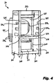
- a soundroof box for a centrifugal fan is indicated 10 as a whole.
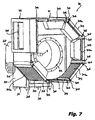
- the fan conventionally comprises a scroll C, that can be seen for example in figure 7 , a wheel (not shown) arranged inside the scroll C, and an electric motor M for driving the wheel G, that can be seen for example in figure 2 .
- the shaft A projecting from the electric motor M, on which the fan wheel is fast, can be seen for example in figure 3 .
- front and rear are referred to a direction from the scroll to the electric motor.
- the soundproof box 10 comprises a soundproof motor covering 20, adapted to encircle the electric motor M of the fan, and a soundproof scroll case 30, adapted to contain the scroll C of the fan.
- the motor covering 20 is applied on a support frame 201, commonly called “chair”, acting as a base for the electric motor M, on the one side, and allowing the scroll C to be assembed, on the other side, as it will be clarified in the following.
- the chair 201 comprises a pair of side frames 203 arranged at opposite sides of the motor M, each of which comprises a pair of uprights 205 and a pair of crosspieces 207, connecting the uprights 205 to each other at opposite ends thereof.
- the side frames 203 are connected to each other by a pair of lower interconnection crosspieces 211, arranged at the base of the chair 201, by an upper interconnection crosspiece 213, arranged close to the top of the chair 201 at the rear side thereof, and by a bracket 215 arranged at a middle height of the chair 201.
- a bracket 215 serves as a support base for the electric motor M.
- the chair 201 described above is made in order to be fitted to different heights of the motor, by changing the height of assembly of the bracket 215.
- the motor covering 20 comprises a plurality of covering members fixed to the chair 201 so as to surround the motor M.
- Such covering members consist in general of sheet panels sheathed by soundproof material on the inner side of the motor covering 20.
- a pair of side panels 221 respectively fixed on the side frames 203 of the chair 201, an upper panel 223 fixed on the top of the chair 201, and a rear covering 225 fixed on the rear side of the chair 201, which extends in height from the top of the chair 201 to below the bracket 215, are provided.
- a partition wall 229 that is sheathed by soundproof material, is formed an opening 229a through which the rear portion of the electric motor M projects, that is therefore arranged in the cavity between the convex portion 227 of the rear covering 225 and the partition wall 229.
- the partition wall 229 separates the inner space of the motor covering 20 into two separated cavities, one of which contains the rear portion of the motor, and the other, arranged above the bracket 215, contains all the remaining portion of the motor. Therefore, the convex portion 227 of the rear covering 225 and the partition wall 229 form a noise trap arranged behind the motor M that, beyond reducing the noise, separates the air intake of the cooling fan (not shown) of the motor with respect to the outlet so that the motor M does not receive already warm air, but always cool air.
- the cooling fan of the motor conventionally arranged at its rear side, sucks cool air through slits 227a formed on the convex portion 227 of the rear covering 225, and directs it along the outer surface of the case of the motor M trough the opening 229a in the partition wall 229. Air warmed by contact with the motor M is therefore discharged through slits 221a formed on the side panels 221.
- the chair 201 has the function, beyond that of supporting the motor and the covering members, of allowing the box to be lifted and palletized, as well as to allow cables to enter the motor.
- the scroll case 30 has a substantially prismatic shape and comprises a pair of terminal walls 301 and a plurality of sidewalls 303 mounted between such terminal walls.
- the terminal walls 301 and the sidewalls 303 consist in general of sheet panels sheathed by soundproof material on the inner side of the scroll case 20.
- some of the sidewalls may have openings at wich planar filters 303a are mounted. Air intaked to the electric fan enters trough the filters 303a.
- a partition wall sheathed by soundproof material, arranged between the scroll C and the terminal wall 301 on the front side, that may be provided for dampening the noise associated with the inlet mouth, which partition wall makes in the substance a double wall on the front side.
- the inlet mouth BA of the fan is free, that is lacks in any pipe connected to it, so that it sucks air directly from the surrounding environment.
- the terminal wall 301 on the front side is provided with an opening for connection to such an intake pipe.
- the scroll case 30 comprises a main portion having the geometry of an octagonal prism provided with angles of 45°, which correspond geometrically to the positions admitted for orientation of the scroll C, and an outlet portion so shaped as to receive the outlet mouth BM of the scroll. Effectively, the scroll case 30 loses the octagonal geometry at the outlet mouth, since its shape fits the outlet mouth BM of the scroll 30.
- the cross-sectional profile of the main portion of the scroll case 30 is defined by a regular octagon portion having six equal sides and six equal angles of 45°.
- the sidewalls 303 of the main portion of the scroll case 30 that has an octagonal geometry are mounted in the following manner.
- a pair of linear interconnection members 305 is mounted at each side corner of the octagonal prism, said members being arranged at opposite sides of the corner, which interconnect the terminal panels 301 of the scroll case 30.
- Each corner is covered by a bent covering plate 307 that is fixed to the respective pair of linear interconnection members 305 of the corner.
- the scroll case can be sized so that is has a reduced width, simply by choosing the linear interconnection members 305 so that they have a smaller length, and sidewalls so that they have 303 a smaller width.
- the sidewalls of the scroll case 30, at the outlet portion of such a case consist of a plurality of panels, some of which are folded at an angle, which are connected to each other and are arranged in such a manner as to leave an opening at the outlet mouth BM of the scroll.
- the sidewalls at the outlet portion of the scroll case 30 are arranged in such a manner to define a shelf or seat, at which a noise reducing plenum 311 of a known type is mounted, in order to attenuate the noise connected with the outlet mouth of the electric fan. In the case in which the outlet mouth is not free but is connected to a pipe, such a noise reducing plenum is not applied.
- connection means are provided for mounting the scroll case 30 on the motor covering 20, which are positioned between the chair 201 and the rear terminal wall 301 of the scroll case 30.
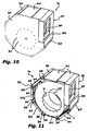
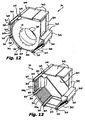
- connection means comprise a set of screw studs 321, that can be seen in particular in figure 11 , which are applied on the rear wall of the scroll C, and are arranged circumferentially around the opening AI formed in such a wall and provided for introduction of the shaft A of the electric motor M.
- the screw studs 321 are adapted to engage corresponding sets of through holes 323, 325, that can be seen in figures 9 and 3 , which are formed on the rear terminal wall 301 of the scroll case 30 and on the front uprights 205 of the chair 201, respectively.
- the screw studs 321 of the scroll C are conventionally arranged according to an octagonal slmmetry around the axis of rotation of the wheel of the electric fan.
- the number of the through holes 323 of the rear terminal wall 301 of the scroll case 30 is equal to the number of the screw studs 321, and such holes are arranged in the same manner as the screw studs 321.
- the through holes 325 on the front upright 205 of the chair 201 are instead four, and they are arranged according to a rectangular diagram.
- the screw studs 321 of the scroll C pass through the through holes 323 of the rear terminal wall 301 of the scroll case 30, and four of them pass also through the through holes 325 on the front uprights 205 of the chair 201.
- fixing of the scroll C, the scroll covering 30 and the chair 201 is conventionally completed by bolts screwed on the screw studs 321 (as an alternative, fixing of the scroll, the scroll case and the chair may be carried out by welding).
- the arrangement of the screw studs 321 and the holes 323, 325 allows the scroll C and the scroll case 30 fast to it, to be selectively mounted according to a plurality of different angular orientations with respect to the chair 201, according to the axis of rotation of the wheel of the electric fan. Moreover, the chair 201 has the favorable effect of stiffening the scroll C.
- the box according to the invention can be shaped according to the different scroll orientations defined by UNI specifications. Moreover, the box can be so shaped as to be fitted to a right-handed of left-handed scroll. This can be carried out simply by overturning each terminal wall 301 of the case of 180°, and by arranging consequently the soundproof material on the face of each of them that is arranged on the inner side of the scroll case 30.
- the invention it is possible to preset a series of different sizes of the terminal walls 301, each of which can receive several similar diameters of wheel, and therefore of the scroll.
- the linear interconnection members 305 and the sidewalls 303 it is sufficient to choose the linear interconnection members 305 and the sidewalls 303 so that their length and their width, respectively, is adapted to receive a scroll having the desired width.
- a series of fans having the same difference of pressure but different flow rate can be received in the same box, only by changing the linear interconnection members and the sidewalls.
- the scroll case in the box according to the invention, can be rotated in order to be fitted to different orientations of the fan, and it can be arranged both according to a right-handed or left-handed configuration, the chair can be composed for different sizes of the motor, and the sidewalls can be replaced in order to be adapted with different widths of the scroll, and to allow filters, possible partition walls and further fittings to be Installed.
- the sidewalls can be replaced in order to be adapted with different widths of the scroll, and to allow filters, possible partition walls and further fittings to be Installed.
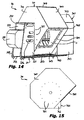
- Such a second embodiment mainly differs from the previous one in the shape of the scroll case 30 and in the presence of an outer noise trap associated with the inlet of the fan.
- the scroll case 30 comprises a main portion having the geometry of an octagonal prism provided with angles of 45°, that correspond geometrically to the orientation positions admitted for the scroll C, as well as an outlet portion so shaped as to receive the outlet mouth BM of the scroll.
- the cross-sectional profile of the main portion of the scroll case 30 is defined by an octagon portion having four equal sides and six equal angles of 45°.
- Such a profile is designed starting from a nominal ottagon, from which a pair of parallel sides extend, and from which furthermore one of such extended sides and one of the other sides perpendicular to it extend, until they are connected to each other.
- a heptagon having six equal angles of 45° and an angle of 90° is obtained, In which four sides are equal to each other, while the two sides adjacent to the angle of 90° and the remaining side parallel to one of the sides adjacent to the angle of 90°, have a length greater than that of the four equal sides (see in particular figure 15 ).
- the portion adjacent to the angle of 90° is intended to receive the outlet mouth BM of the scroll.
- the scroll case 30 lacks in any inlet openings on the sidewalls 303, while an opening 331 aligned with the inlet mouth BA of the scroll (see figure 17 ) is formed on the front terminal wall 301.
- a noise trap 341 that surrounds the opening 331 is fixed on the terminal wall 301, at such an opening.
- the noise trap 341 has a substantially prismatic shape and comprises a pair of terminal walls 342 and a plurality of side walls 343 mounted between the terminal walls 342.
- the rear terminal wall 342 of the trap is fixed to the front terminal wall 301 of the scroll case 30.
- the terminal walls 342 and the side walls 343 consist in general of sheet panels sheathed by soundproof material on the inner side of the trap 341. According to the requirements, and such as In the example shown, some of the sidewalls may have openings at which planar filters to you 343a are mounted. Entry of inlet air to the electric fan takes place through the filters 343a.
- shaped slits 251 are formed on the side panels 221 of the motor covering, in order to allow the chair 201 to be hooked and transported by a lifting system (not shown).
- a pair of support beams 253 fixed on opposite sides of the chair 201 can be seen, which extend below the scroll case 30 and the outer noise trap 341 in order to provide a support for them.
- the boxes described can be fitted to other installation configurations different from those shown, In particular, they can be fitted to a configuration in which the chair supports a shaft connected to the wheel, which shaft receives the motion through a transmission from an electric motor also supported by the chair.
- the scroll case is similar to those described above, and it is mounted on the chair.
- the motor covering can be made such as a soundproof box applied to the chair around the motor only, or such as a larger case surrounding both the motor and the whole chair.
Landscapes
- Engineering & Computer Science (AREA)
- Mechanical Engineering (AREA)
- General Engineering & Computer Science (AREA)
- Structures Of Non-Positive Displacement Pumps (AREA)
Claims (12)
- Schallgedämmtes Gehäuse für ein Zentrifugalgebläse umfassend:- ein Traggestell (201) für einen Motor (M) des Gebläses auf einer Seite und zur Aufnahme einer Schnecke (c) des Gebläses auf der anderen Seite,- ein schallgedämmtes Schneckengehäuse (30), das die Schnecke aufnimmt und das eine im wesentlichen prismatische Form mit zwei Endwänden (301) und mehreren Seitenwänden (303) hat, die zwischen den Endwänden (301) angebracht sind,- Verbindungsmittel (321, 323, 325) zur Befestigung des Schneckengehäuses (30) an dem Traggestell (201), die zwischen dem Traggestell und den Endwänden des Schneckengehäuses angeordnet sind,dadurch gekennzeichnet, dass das schallgedämmte Schneckengehäuse (30) zusätzlich eine schallgedämmte Motorabdeckung (20) hat, die an dem Traggestell (201) angebracht ist, den Motor (M) einhüllt und von dem Schneckengehäuse (30) getrennt ist, und dass die Verbindungsmittel (321, 323, 325) so angeordnet sind, dass das Schneckengehäuse (30) wahlweise in verschiedenen Winkelstellungen relativ zu dem Traggestell (201) um die Drehachse des Gebläserades montierbar ist, welche den zugeordneten Winkelstellungen der Schnecke (c) entsprechen.
- Gehäuse nach Anspruch 1, dadurch gekennzeichnet, dass das Traggestell zwei seitliche Rahmen (203) hat, zwischen denen eine Konsole (215) angebracht ist, die als Trägerplatte für den Motor dient, wobei die Motorabdeckung aus Abdeckelementen (221, 223, 225, 229) zusammengesetzt ist, die an dem Traggestell so befestigt sind, dass sie den Motor einschließen, und die aus Platten bestehen, die an der Innenseite der Motorabdeckung (20) mit einem schalldämmenden Material beschichtet sind.
- Gehäuse nach Anspruch 2, dadurch gekennzeichnet, dass die Abdeckelemente auf der der Schnecke gegenüberliegenden Seite ein hinteres Abdeckelement (225) aufweisen, von dem ein konvexer Abschnitt (227) absteht, der einen Hohlraum zur Aufnahme eines hinteren Teils des Motors bildet, sowie eine flache Trennwand (229) zwischen dem Hohlraum und einem weiteren, den restlichen Teil des Motors aufnehmenden Hohlraum, wobei der konvexe Abschnitt des hinteren Abdeckelementes (225) und die Trennwand (229) eine Geräuschfalle für den Motor sowie eine Trennung zwischen dem Eintritt (227a) und dem Austritt (221a) der Motorkühlluft bilden.
- Gehäuse nach einem der vorhergehenden Ansprüche, dadurch gekennzeichnet, dass das Schneckengehäuse (30) einen Hauptteil hat, der der Geometrie eines achteckigen Prismas mit Winkeln von 45° entspricht, sowie einen Austrittsteil, der so geformt ist, dass er die Austrittsöffnung (BM) der Motorschnecke bildet.
- Gehäuse nach Anspruch 4, dadurch gekennzeichnet, dass der Hauptteil des Schneckengehäuses ein Querschnittsprofil hat, das definiert ist durch einen Abschnitt eines regelmäßigen Achtecks mit sechs gleichen Seiten und sechs Winkeln von jeweils 45°.
- Gehäuse nach Anspruch 4, dadurch gekennzeichnet, dass das Schneckengehäuse (30) ein Querschnittsprofil hat, das definiert ist durch ein Siebeneck mit sechs Winkeln von je 45° und einem Winkel von 90° und vier untereinander gleichen Seiten, während die beiden an den Winkel von 90° angrenzenden Seiten sowie die verbleibende Seite, die parallel zu einer der an den rechten Winkel angrenzenden Seiten verläuft, eine größere Länge als die vier gleichen Seiten haben.
- Gehäuse nach einem der Ansprüche 4 bis 6, dadurch gekennzeichnet, dass im Hauptteil des Schneckengehäuses (30) im Bereich jeder Seitenkante des achteckigen Prismas ein Paar linearer Verbindungselemente (305) angebracht ist, die auf gegenüberliegenden Seiten der Kante liegen und die Endwände (301) des Schneckengehäuses (30) miteinander verbinden, wobei die linearen Verbindungselemente (305), die jeder einzelnen Seitenfläche des achteckigen Prismas zugeordnet sind, als Montagerahmen für die entsprechende Seitenwand (303) des Schneckengehäuses (30) dienen.
- Gehäuse nach Anspruch 7, dadurch gekennzeichnet, dass jede Seitenkante des achteckigen Prismas durch eine abgekantete Deckplatte (307) abgedeckt ist, die an dem zugehörigem Paar der linearen Verbindungselemente (305) der Kante befestigt ist.
- Gehäuse nach einem der vorhergehenden Ansprüche, dadurch gekennzeichnet, dass in dem Schneckengehäuse eine mit schalldämmendem Material beschichtete Trennwand angeordnet ist, die zwischen die Schnecke (c) und die Endwand (301) des Schneckengehäuses (30) auf der dem Motor gegenüberliegenden Seite eingesetzt ist.
- Gehäuse nach einem der Ansprüche 4 bis 9, dadurch gekennzeichnet, dass an dem Austrittsteil des Schneckengehäuses eine schallschluckende Kammer (Plenum) (311) angebracht ist.
- Gehäuse nach einem der vorhergehenden Ansprüche, dadurch gekennzeichnet, dass in die dem Motor gegenüberliegende Seite der Endwand (301) eine Öffnung (331) eingearbeitet ist, die mit der Ausgangsöffnung (BA) der Schnecke fluchtet, wobei im Bereich dieser Öffnung eine äußere Geräuschfalle (341) angebracht ist, die diese Öffnung umgibt und die eine im wesentlichen prismatische Form mit zwei Endwänden (342) und mehreren, zwischen diesen angebrachten Seitenwänden (343) hat, wobei die Endwände und die Seitenwände an der Innenseite der äußeren Geräuschefalle aus mit einem schalldämmenden Material beschichteten Platten bestehen.
- Gehäuse nach einem der vorhergehenden Ansprüche, dadurch gekennzeichnet, dass die Verbindungsmittel aus einer Reihe von Stiftschrauben (321) bestehen, die in eine der Endwände der Schnecke (c) über den Umfang verteilt eingesetzt sind und in entsprechende Durchgangsbohrungen (323, 325) eingreifen, welche in eine der Endwände des Schneckengehäuses (30) und in das Traggestell (201) eingearbeitet sind.
Applications Claiming Priority (1)
| Application Number | Priority Date | Filing Date | Title |
|---|---|---|---|
| ITTO2009A001018A IT1397593B1 (it) | 2009-12-21 | 2009-12-21 | Cabina insonorizzante per un ventilatore centrifugo. |
Publications (2)
| Publication Number | Publication Date |
|---|---|
| EP2336574A1 EP2336574A1 (de) | 2011-06-22 |
| EP2336574B1 true EP2336574B1 (de) | 2012-07-11 |
Family
ID=42299184
Family Applications (1)
| Application Number | Title | Priority Date | Filing Date |
|---|---|---|---|
| EP20100015815 Not-in-force EP2336574B1 (de) | 2009-12-21 | 2010-12-20 | Schalldichtbehälter für einen Radiallüfter |
Country Status (2)
| Country | Link |
|---|---|
| EP (1) | EP2336574B1 (de) |
| IT (1) | IT1397593B1 (de) |
Families Citing this family (4)
| Publication number | Priority date | Publication date | Assignee | Title |
|---|---|---|---|---|
| JP5755166B2 (ja) * | 2012-02-29 | 2015-07-29 | 三菱電機株式会社 | 送風機 |
| DE202015102251U1 (de) * | 2015-05-04 | 2016-08-05 | Rehau Ag & Co | Lüftereinheit zur Be- und Entlüftung von Räumen eines Gebäudes und Rahmenbaugruppe, die eine derartige Lüftereinheit umfasst |
| FR3064701B1 (fr) * | 2017-03-30 | 2019-06-28 | Smv | Dispositif d'insonorisation pour un ventilateur centrifuge |
| US11885526B2 (en) * | 2021-04-14 | 2024-01-30 | Lennox Industries Inc. | High-performance housings for backward-curved blowers |
Family Cites Families (4)
| Publication number | Priority date | Publication date | Assignee | Title |
|---|---|---|---|---|
| US1163543A (en) * | 1912-06-10 | 1915-12-07 | Robert A Ilg | Rotary blower. |
| GB741975A (en) * | 1953-11-18 | 1955-12-14 | Matthews & Yates Ltd | Improvements relating to fans |
| FR1327918A (fr) * | 1962-04-13 | 1963-05-24 | Perfectionnements aux bâtis-supports de ventilateurs centrifuges | |
| US4174020A (en) * | 1975-07-01 | 1979-11-13 | Challis Louis A | Acoustic treatment for fans |
-
2009
- 2009-12-21 IT ITTO2009A001018A patent/IT1397593B1/it active
-
2010
- 2010-12-20 EP EP20100015815 patent/EP2336574B1/de not_active Not-in-force
Also Published As
| Publication number | Publication date |
|---|---|
| IT1397593B1 (it) | 2013-01-16 |
| ITTO20091018A1 (it) | 2011-06-22 |
| EP2336574A1 (de) | 2011-06-22 |
Similar Documents
| Publication | Publication Date | Title |
|---|---|---|
| EP2336574B1 (de) | Schalldichtbehälter für einen Radiallüfter | |
| US10962238B2 (en) | Air conditioner and blower device | |
| US20090178296A1 (en) | Apparatus and method for drying containers for beverages | |
| EP2993419B1 (de) | Luftreiniger | |
| US6019808A (en) | Air cleaner | |
| EP2047782B1 (de) | Sauger mit mehreren Abgaspunkten | |
| KR960028953A (ko) | 송풍기 및 필터 어셈블리 | |
| US20060217056A1 (en) | Fan/filter unit and clean booth equipeed therewith | |
| US12510266B2 (en) | Fan powered exhaust hood | |
| KR102653024B1 (ko) | 공기 조화기의 실내기 | |
| KR102687748B1 (ko) | 공기조화기 | |
| JP3855991B2 (ja) | ファンフィルターユニット | |
| WO2012133392A1 (ja) | 熱源ユニット | |
| CN1073256A (zh) | 用于食品的气体处理设备 | |
| JP7752594B2 (ja) | ファンフィルタユニット | |
| KR20090080749A (ko) | 천장형 공기조화기 | |
| EP4480369B1 (de) | Geräuschminderungsvorrichtung für reinigungsgeräte | |
| CN217190474U (zh) | 一种用于金属制品的自动喷涂装置 | |
| KR102659687B1 (ko) | 배기 장치 | |
| KR102653025B1 (ko) | 공기 조화기의 실내기 | |
| US20250283632A1 (en) | Air cleaner | |
| JP5225936B2 (ja) | ファンフィルタユニット | |
| KR102778012B1 (ko) | 공기청정기, 및 공기청정시스템 | |
| JP3893307B2 (ja) | 穀物乾燥装置 | |
| WO2024157650A1 (ja) | 室外機用保護部材および冷凍サイクル装置 |
Legal Events
| Date | Code | Title | Description |
|---|---|---|---|
| PUAI | Public reference made under article 153(3) epc to a published international application that has entered the european phase |
Free format text: ORIGINAL CODE: 0009012 |
|
| AK | Designated contracting states |
Kind code of ref document: A1 Designated state(s): AL AT BE BG CH CY CZ DE DK EE ES FI FR GB GR HR HU IE IS IT LI LT LU LV MC MK MT NL NO PL PT RO RS SE SI SK SM TR |
|
| AX | Request for extension of the european patent |
Extension state: BA ME |
|
| 17P | Request for examination filed |
Effective date: 20111219 |
|
| GRAP | Despatch of communication of intention to grant a patent |
Free format text: ORIGINAL CODE: EPIDOSNIGR1 |
|
| RIC1 | Information provided on ipc code assigned before grant |
Ipc: F04D 29/42 20060101AFI20120117BHEP Ipc: F04D 29/62 20060101ALI20120117BHEP Ipc: F04D 29/66 20060101ALI20120117BHEP |
|
| GRAS | Grant fee paid |
Free format text: ORIGINAL CODE: EPIDOSNIGR3 |
|
| GRAA | (expected) grant |
Free format text: ORIGINAL CODE: 0009210 |
|
| AK | Designated contracting states |
Kind code of ref document: B1 Designated state(s): AL AT BE BG CH CY CZ DE DK EE ES FI FR GB GR HR HU IE IS IT LI LT LU LV MC MK MT NL NO PL PT RO RS SE SI SK SM TR |
|
| REG | Reference to a national code |
Ref country code: GB Ref legal event code: FG4D |
|
| REG | Reference to a national code |
Ref country code: CH Ref legal event code: EP |
|
| REG | Reference to a national code |
Ref country code: AT Ref legal event code: REF Ref document number: 566291 Country of ref document: AT Kind code of ref document: T Effective date: 20120715 |
|
| REG | Reference to a national code |
Ref country code: IE Ref legal event code: FG4D |
|
| REG | Reference to a national code |
Ref country code: DE Ref legal event code: R096 Ref document number: 602010002126 Country of ref document: DE Effective date: 20120906 |
|
| REG | Reference to a national code |
Ref country code: CH Ref legal event code: NV Representative=s name: MICHELI & CIE SA |
|
| REG | Reference to a national code |
Ref country code: NL Ref legal event code: VDEP Effective date: 20120711 |
|
| REG | Reference to a national code |
Ref country code: AT Ref legal event code: MK05 Ref document number: 566291 Country of ref document: AT Kind code of ref document: T Effective date: 20120711 |
|
| REG | Reference to a national code |
Ref country code: LT Ref legal event code: MG4D Effective date: 20120711 |
|
| PG25 | Lapsed in a contracting state [announced via postgrant information from national office to epo] |
Ref country code: FI Free format text: LAPSE BECAUSE OF FAILURE TO SUBMIT A TRANSLATION OF THE DESCRIPTION OR TO PAY THE FEE WITHIN THE PRESCRIBED TIME-LIMIT Effective date: 20120711 Ref country code: CY Free format text: LAPSE BECAUSE OF FAILURE TO SUBMIT A TRANSLATION OF THE DESCRIPTION OR TO PAY THE FEE WITHIN THE PRESCRIBED TIME-LIMIT Effective date: 20120711 Ref country code: BE Free format text: LAPSE BECAUSE OF FAILURE TO SUBMIT A TRANSLATION OF THE DESCRIPTION OR TO PAY THE FEE WITHIN THE PRESCRIBED TIME-LIMIT Effective date: 20120711 Ref country code: AT Free format text: LAPSE BECAUSE OF FAILURE TO SUBMIT A TRANSLATION OF THE DESCRIPTION OR TO PAY THE FEE WITHIN THE PRESCRIBED TIME-LIMIT Effective date: 20120711 Ref country code: IS Free format text: LAPSE BECAUSE OF FAILURE TO SUBMIT A TRANSLATION OF THE DESCRIPTION OR TO PAY THE FEE WITHIN THE PRESCRIBED TIME-LIMIT Effective date: 20121111 Ref country code: LT Free format text: LAPSE BECAUSE OF FAILURE TO SUBMIT A TRANSLATION OF THE DESCRIPTION OR TO PAY THE FEE WITHIN THE PRESCRIBED TIME-LIMIT Effective date: 20120711 Ref country code: NO Free format text: LAPSE BECAUSE OF FAILURE TO SUBMIT A TRANSLATION OF THE DESCRIPTION OR TO PAY THE FEE WITHIN THE PRESCRIBED TIME-LIMIT Effective date: 20121011 Ref country code: HR Free format text: LAPSE BECAUSE OF FAILURE TO SUBMIT A TRANSLATION OF THE DESCRIPTION OR TO PAY THE FEE WITHIN THE PRESCRIBED TIME-LIMIT Effective date: 20120711 |
|
| PG25 | Lapsed in a contracting state [announced via postgrant information from national office to epo] |
Ref country code: GR Free format text: LAPSE BECAUSE OF FAILURE TO SUBMIT A TRANSLATION OF THE DESCRIPTION OR TO PAY THE FEE WITHIN THE PRESCRIBED TIME-LIMIT Effective date: 20121012 Ref country code: PL Free format text: LAPSE BECAUSE OF FAILURE TO SUBMIT A TRANSLATION OF THE DESCRIPTION OR TO PAY THE FEE WITHIN THE PRESCRIBED TIME-LIMIT Effective date: 20120711 Ref country code: LV Free format text: LAPSE BECAUSE OF FAILURE TO SUBMIT A TRANSLATION OF THE DESCRIPTION OR TO PAY THE FEE WITHIN THE PRESCRIBED TIME-LIMIT Effective date: 20120711 Ref country code: SE Free format text: LAPSE BECAUSE OF FAILURE TO SUBMIT A TRANSLATION OF THE DESCRIPTION OR TO PAY THE FEE WITHIN THE PRESCRIBED TIME-LIMIT Effective date: 20120711 Ref country code: SI Free format text: LAPSE BECAUSE OF FAILURE TO SUBMIT A TRANSLATION OF THE DESCRIPTION OR TO PAY THE FEE WITHIN THE PRESCRIBED TIME-LIMIT Effective date: 20120711 Ref country code: PT Free format text: LAPSE BECAUSE OF FAILURE TO SUBMIT A TRANSLATION OF THE DESCRIPTION OR TO PAY THE FEE WITHIN THE PRESCRIBED TIME-LIMIT Effective date: 20121112 |
|
| PG25 | Lapsed in a contracting state [announced via postgrant information from national office to epo] |
Ref country code: NL Free format text: LAPSE BECAUSE OF FAILURE TO SUBMIT A TRANSLATION OF THE DESCRIPTION OR TO PAY THE FEE WITHIN THE PRESCRIBED TIME-LIMIT Effective date: 20120711 |
|
| PG25 | Lapsed in a contracting state [announced via postgrant information from national office to epo] |
Ref country code: EE Free format text: LAPSE BECAUSE OF FAILURE TO SUBMIT A TRANSLATION OF THE DESCRIPTION OR TO PAY THE FEE WITHIN THE PRESCRIBED TIME-LIMIT Effective date: 20120711 Ref country code: DK Free format text: LAPSE BECAUSE OF FAILURE TO SUBMIT A TRANSLATION OF THE DESCRIPTION OR TO PAY THE FEE WITHIN THE PRESCRIBED TIME-LIMIT Effective date: 20120711 Ref country code: ES Free format text: LAPSE BECAUSE OF FAILURE TO SUBMIT A TRANSLATION OF THE DESCRIPTION OR TO PAY THE FEE WITHIN THE PRESCRIBED TIME-LIMIT Effective date: 20121022 Ref country code: RO Free format text: LAPSE BECAUSE OF FAILURE TO SUBMIT A TRANSLATION OF THE DESCRIPTION OR TO PAY THE FEE WITHIN THE PRESCRIBED TIME-LIMIT Effective date: 20120711 Ref country code: CZ Free format text: LAPSE BECAUSE OF FAILURE TO SUBMIT A TRANSLATION OF THE DESCRIPTION OR TO PAY THE FEE WITHIN THE PRESCRIBED TIME-LIMIT Effective date: 20120711 |
|
| PLBE | No opposition filed within time limit |
Free format text: ORIGINAL CODE: 0009261 |
|
| STAA | Information on the status of an ep patent application or granted ep patent |
Free format text: STATUS: NO OPPOSITION FILED WITHIN TIME LIMIT |
|
| PG25 | Lapsed in a contracting state [announced via postgrant information from national office to epo] |
Ref country code: SK Free format text: LAPSE BECAUSE OF FAILURE TO SUBMIT A TRANSLATION OF THE DESCRIPTION OR TO PAY THE FEE WITHIN THE PRESCRIBED TIME-LIMIT Effective date: 20120711 |
|
| 26N | No opposition filed |
Effective date: 20130412 |
|
| PG25 | Lapsed in a contracting state [announced via postgrant information from national office to epo] |
Ref country code: MC Free format text: LAPSE BECAUSE OF NON-PAYMENT OF DUE FEES Effective date: 20121231 Ref country code: BG Free format text: LAPSE BECAUSE OF FAILURE TO SUBMIT A TRANSLATION OF THE DESCRIPTION OR TO PAY THE FEE WITHIN THE PRESCRIBED TIME-LIMIT Effective date: 20121011 Ref country code: RS Free format text: LAPSE BECAUSE OF FAILURE TO SUBMIT A TRANSLATION OF THE DESCRIPTION OR TO PAY THE FEE WITHIN THE PRESCRIBED TIME-LIMIT Effective date: 20120711 |
|
| REG | Reference to a national code |
Ref country code: DE Ref legal event code: R097 Ref document number: 602010002126 Country of ref document: DE Effective date: 20130412 |
|
| REG | Reference to a national code |
Ref country code: IE Ref legal event code: MM4A |
|
| PG25 | Lapsed in a contracting state [announced via postgrant information from national office to epo] |
Ref country code: IE Free format text: LAPSE BECAUSE OF NON-PAYMENT OF DUE FEES Effective date: 20121220 |
|
| PG25 | Lapsed in a contracting state [announced via postgrant information from national office to epo] |
Ref country code: MT Free format text: LAPSE BECAUSE OF FAILURE TO SUBMIT A TRANSLATION OF THE DESCRIPTION OR TO PAY THE FEE WITHIN THE PRESCRIBED TIME-LIMIT Effective date: 20120711 Ref country code: AL Free format text: LAPSE BECAUSE OF FAILURE TO SUBMIT A TRANSLATION OF THE DESCRIPTION OR TO PAY THE FEE WITHIN THE PRESCRIBED TIME-LIMIT Effective date: 20120711 |
|
| PG25 | Lapsed in a contracting state [announced via postgrant information from national office to epo] |
Ref country code: TR Free format text: LAPSE BECAUSE OF FAILURE TO SUBMIT A TRANSLATION OF THE DESCRIPTION OR TO PAY THE FEE WITHIN THE PRESCRIBED TIME-LIMIT Effective date: 20120711 |
|
| PG25 | Lapsed in a contracting state [announced via postgrant information from national office to epo] |
Ref country code: SM Free format text: LAPSE BECAUSE OF FAILURE TO SUBMIT A TRANSLATION OF THE DESCRIPTION OR TO PAY THE FEE WITHIN THE PRESCRIBED TIME-LIMIT Effective date: 20120711 Ref country code: LU Free format text: LAPSE BECAUSE OF NON-PAYMENT OF DUE FEES Effective date: 20121220 |
|
| PGFP | Annual fee paid to national office [announced via postgrant information from national office to epo] |
Ref country code: FR Payment date: 20131220 Year of fee payment: 4 |
|
| PG25 | Lapsed in a contracting state [announced via postgrant information from national office to epo] |
Ref country code: HU Free format text: LAPSE BECAUSE OF FAILURE TO SUBMIT A TRANSLATION OF THE DESCRIPTION OR TO PAY THE FEE WITHIN THE PRESCRIBED TIME-LIMIT Effective date: 20101220 |
|
| PGFP | Annual fee paid to national office [announced via postgrant information from national office to epo] |
Ref country code: DE Payment date: 20150226 Year of fee payment: 5 |
|
| PG25 | Lapsed in a contracting state [announced via postgrant information from national office to epo] |
Ref country code: MK Free format text: LAPSE BECAUSE OF FAILURE TO SUBMIT A TRANSLATION OF THE DESCRIPTION OR TO PAY THE FEE WITHIN THE PRESCRIBED TIME-LIMIT Effective date: 20120711 |
|
| REG | Reference to a national code |
Ref country code: CH Ref legal event code: PL |
|
| GBPC | Gb: european patent ceased through non-payment of renewal fee |
Effective date: 20141220 |
|
| REG | Reference to a national code |
Ref country code: FR Ref legal event code: ST Effective date: 20150831 |
|
| PG25 | Lapsed in a contracting state [announced via postgrant information from national office to epo] |
Ref country code: LI Free format text: LAPSE BECAUSE OF NON-PAYMENT OF DUE FEES Effective date: 20141231 Ref country code: CH Free format text: LAPSE BECAUSE OF NON-PAYMENT OF DUE FEES Effective date: 20141231 Ref country code: GB Free format text: LAPSE BECAUSE OF NON-PAYMENT OF DUE FEES Effective date: 20141220 |
|
| PG25 | Lapsed in a contracting state [announced via postgrant information from national office to epo] |
Ref country code: FR Free format text: LAPSE BECAUSE OF NON-PAYMENT OF DUE FEES Effective date: 20141231 |
|
| REG | Reference to a national code |
Ref country code: DE Ref legal event code: R119 Ref document number: 602010002126 Country of ref document: DE |
|
| PG25 | Lapsed in a contracting state [announced via postgrant information from national office to epo] |
Ref country code: DE Free format text: LAPSE BECAUSE OF NON-PAYMENT OF DUE FEES Effective date: 20160701 |
|
| PGFP | Annual fee paid to national office [announced via postgrant information from national office to epo] |
Ref country code: IT Payment date: 20171227 Year of fee payment: 8 |
|
| PG25 | Lapsed in a contracting state [announced via postgrant information from national office to epo] |
Ref country code: IT Free format text: LAPSE BECAUSE OF NON-PAYMENT OF DUE FEES Effective date: 20181220 |