EP3428347B1 - Small hydraulic shovel with level gauge for the hydraulic fluid tank - Google Patents
Small hydraulic shovel with level gauge for the hydraulic fluid tank Download PDFInfo
- Publication number
- EP3428347B1 EP3428347B1 EP17762670.2A EP17762670A EP3428347B1 EP 3428347 B1 EP3428347 B1 EP 3428347B1 EP 17762670 A EP17762670 A EP 17762670A EP 3428347 B1 EP3428347 B1 EP 3428347B1
- Authority
- EP
- European Patent Office
- Prior art keywords
- hydraulic oil
- level gauge
- oil tank
- outer cover
- attachment member
- Prior art date
- Legal status (The legal status is an assumption and is not a legal conclusion. Google has not performed a legal analysis and makes no representation as to the accuracy of the status listed.)
- Active
Links
Images


Classifications
-
- E—FIXED CONSTRUCTIONS
- E02—HYDRAULIC ENGINEERING; FOUNDATIONS; SOIL SHIFTING
- E02F—DREDGING; SOIL-SHIFTING
- E02F9/00—Component parts of dredgers or soil-shifting machines, not restricted to one of the kinds covered by groups E02F3/00 - E02F7/00
-
- E—FIXED CONSTRUCTIONS
- E02—HYDRAULIC ENGINEERING; FOUNDATIONS; SOIL SHIFTING
- E02F—DREDGING; SOIL-SHIFTING
- E02F3/00—Dredgers; Soil-shifting machines
- E02F3/04—Dredgers; Soil-shifting machines mechanically-driven
- E02F3/28—Dredgers; Soil-shifting machines mechanically-driven with digging tools mounted on a dipper- or bucket-arm, i.e. there is either one arm or a pair of arms, e.g. dippers, buckets
- E02F3/30—Dredgers; Soil-shifting machines mechanically-driven with digging tools mounted on a dipper- or bucket-arm, i.e. there is either one arm or a pair of arms, e.g. dippers, buckets with a dipper-arm pivoted on a cantilever beam, i.e. boom
- E02F3/32—Dredgers; Soil-shifting machines mechanically-driven with digging tools mounted on a dipper- or bucket-arm, i.e. there is either one arm or a pair of arms, e.g. dippers, buckets with a dipper-arm pivoted on a cantilever beam, i.e. boom working downwardly and towards the machine, e.g. with backhoes
- E02F3/325—Backhoes of the miniature type
-
- E—FIXED CONSTRUCTIONS
- E02—HYDRAULIC ENGINEERING; FOUNDATIONS; SOIL SHIFTING
- E02F—DREDGING; SOIL-SHIFTING
- E02F9/00—Component parts of dredgers or soil-shifting machines, not restricted to one of the kinds covered by groups E02F3/00 - E02F7/00
- E02F9/08—Superstructures; Supports for superstructures
- E02F9/0858—Arrangement of component parts installed on superstructures not otherwise provided for, e.g. electric components, fenders, air-conditioning units
- E02F9/0883—Tanks, e.g. oil tank, urea tank, fuel tank
-
- G—PHYSICS
- G01—MEASURING; TESTING
- G01F—MEASURING VOLUME, VOLUME FLOW, MASS FLOW OR LIQUID LEVEL; METERING BY VOLUME
- G01F23/00—Indicating or measuring liquid level or level of fluent solid material, e.g. indicating in terms of volume or indicating by means of an alarm
- G01F23/02—Indicating or measuring liquid level or level of fluent solid material, e.g. indicating in terms of volume or indicating by means of an alarm by gauge glasses or other apparatus involving a window or transparent tube for directly observing the level to be measured or the level of a liquid column in free communication with the main body of the liquid
Definitions
- the present invention relates to a small-sized hydraulic excavator which operates at such working sites as building premises and narrow housing lots, more particularly, to a small-sized hydraulic excavator having an area in which various equipment and machinery, structural members arranged on a revolving upperstructure are disposed narrower, and being subject to restrictions particularly on the disposition of a hydraulic oil tank, since widths of a travel base and the revolving upperstructure are restricted, the travel base being provided with crawler type travel apparatuses within such a base width as enabling such travel base to pass through narrow passages, the revolving upperstructure being turnably mounted on the upper part of the travel base, and being provided with a cab.
- Patent Literature 1 there is prior disclosure on such a small-sized hydraulic excavator as mentioned above in Patent Literature 1 below.
- a small-sized hydraulic excavator which operates at such working sites as building premises and narrow housing lots, more particularly, to a small-sized hydraulic excavator called as a mini excavator having an area in which various equipment and machinery, structural members arranged on a revolving upperstructure are disposed narrower, and being subject to restrictions particularly on the disposition of a hydraulic oil tank, since widths of a travel base and the revolving upperstructure are restricted, the travel base being provided with crawler type travel apparatuses within such a base width as enabling such travel base to pass through narrow passages, the revolving upperstructure being turnably mounted on the upper part of the travel base, and being provided with a cab.
- This prior small-sized excavator comprises a travel base provided with a pair of right and left crawler type travel apparatuses; a revolving upperstructure disposed on the travel base such that it is turnable; and a working machine (such as a boom, an arm, a bucket, a boom cylinder, an arm cylinder, a bucket cylinder and the like) attached to a right and left swinging swing post disposed on a frontal end frame portion protruding forward from the revolving frame of the revolving upperstructure such that the working machine is vertically rotatable.
- a working machine such as a boom, an arm, a bucket, a boom cylinder, an arm cylinder, a bucket cylinder and the like
- a cab (driver's cabin) is disposed on the revolving frame of the revolving upperstructure from the tip end side of the revolving frame to its rear side beyond a center at which the revolving frame revolves and the width of the cab with respect to its right and left direction (the width between the right and left side faces of the cab) is the same or approximately the same as the width of the above-mentioned travel base provided with a pair of right and left crawler type travel apparatuses.
- Such tanks as a hydraulic oil tank and a fuel tank as well as a group of switching valves comprising a plurality of directional control valves are disposed from the vicinity of the center of the revolving frame within the cab to its rear side and behind such equipment and machinery an engine, a hydraulic pump, a heat exchanger composed of a radiator and an oil cooler etc. and the like are disposed.
- a counterweight whose outer circumference takes an arch shape and with which such working machine is counterbalanced is disposed at the revolving frame behind the cab.
- an outer cover is attached to the revolving frame behind the cab such that the outer cover surrounds such tanks as the hydraulic oil tank and the fuel tank, an engine, a hydraulic pump and a heat exchanger composed of a radiator and an oil cooler etc. from the vicinity of the center of the cab to the counterweight.
- This outer cover is disposed from the right and left side faces of the cab to its rear side, in which the width of the right and left sides of the outer cover is the same or approximately the same as that of the above-mentioned travel base provided with the pair of right and left crawler type travel apparatuses in the same way as the width between the right and left side faces of the cab.
- the hydraulic pump and the heat exchanger composed of a radiator and an oil cooler etc.
- a partitioning plate forming an engine room along with the outer cover is disposed continuously from a floor disposed in front of the cab and a driver's seat is mounted on the partitioning plate.
- the hydraulic oil tank is positioned below the partitioning plate within the cab and mounted on the revolving frame of the revolving upperstructure as well as is disposed with a certain clearance with the outer cover. A hydraulic oil supplied to the respective actuators of the hydraulic driving system for driving the travel base, the revolving upperstructure and the working machine is received in the hydraulic oil tank.
- a level gauge which regulates the volume of the hydraulic oil received in the hydraulic oil tank and whose inside is hollow is provided on the hydraulic oil tank such that the level gauge is opposed to a checking hole formed on one side face of the right and left side faces of the outer cover (e.g. the side face opposed to an entrance door disposed on one side face of the cab).
- This level gauge includes a circular protruding portion jutting out of the side face of the hydraulic oil tank to secure the volume of the hydraulic oil tank as large as possible; and a window which is provided on the outer cover side face of the protruding portion and is made from a transparent member which enables the top surface of the hydraulic oil received in the corresponding tank to be visually checked through the checking hole formed on the outer cover.
- EP 2 679 727 A1 discloses a small-sized hydraulic excavator in accordance with the preamble of claim 1.
- the small-sized hydraulic excavator such as the above-mentioned mini excavator has restriction in the width of its travel base and revolving upperstructure respectively such that it is fit to a cramped working space, so that an error upon assembly resulting from mounting a number of parts and members within the limited and crumped area of the cab on the revolving frame constituting the revolving upperstructure might cause the window of the level gauge to slightly protrude from the checking hole of the outer cover.
- the small-sized hydraulic excavator With the small-sized hydraulic excavator assembled as above, it facilitates the volume of the hydraulic oil received in the hydraulic oil tank to be readily checked, but there is apprehension that an external force might be applied to the window of the level gauge by such window making into contact with the branches and twigs of the hedging trees planted in the neighboring houses upon such excavator being operated at a housing lot where there are lined a number of houses adjacent to each other so as to make the level gauge damaged.
- the present invention is to provide a small-sized excavator capable of suppressing an external force arising upon excavation work from being applied to the level gauge provided on the hydraulic oil tank.
- the small-sized hydraulic excavator of the invention comprises the features of claim 1.
- the small-sized hydraulic excavator according to the present invention includes: a travel base; a revolving upperstructure disposed on the travel base; a working machine attached to a right and left swinging swing post disposed on a frontal end frame portion protruding forward from the revolving frame of the revolving upperstructure such that the working machine is vertically rotatable; a cab which is disposed on the revolving frame of the revolving upperstructure from a tip end side of the revolving frame to its rear side beyond a center at which the revolving frame revolves and a right and left width of which takes a widthwise shape along a width of the travel base; an outer cover which is disposed from a vicinity of a center of the cab to a counterweight disposed to a rear end of the revolving upperstructure on the revolving
- the attachment member which is fixed on the side face of the hydraulic oil tank and to which the level gauge is attached is formed with a shape which surrounds the periphery of the protruding portion of the level gauge and the attachment member is provided such that its end face is made flush with the side face of the protruding portion of the level gauge or protrudes from the side face of the protruding portion of the level gauge, so that the attachment member receives external force arising upon excavation work, with the result that it suppresses such external force from being applied to the level gauge.
- a highly reliable small-sized hydraulic excavator with the level gauge protected from such external force with higher precision than the conventional counterpart is provided.
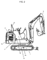
- the small-sized hydraulic excavator (a mini excavator being exemplified herein according to the present embodiment) includes: a travel base 1 provided with a pair of right and left crawler type travel apparatuses 1a; a revolving upperstructure 2 disposed on the travel base 1 such that it is turnable; and a working machine 3 (including a boom, an arm, a bucket, a boom cylinder, an arm cylinder and a bucket cylinder etc.) which is attached to a right and left swinging swing post 2c disposed on a frontal end frame portion 2b protruding forward from a revolving frame 2a of the revolving upperstructure 2 such that the working machine is vertically rotatable and carry out e.g.
- a cab (driver's cabin) 13 is disposed on the revolving frame 2a of the revolving upperstructure 2 from the tip end side of the revolving frame 2a to its rear side beyond a center at which the revolving frame 2a revolves; and the right and left width of the cab 13 (namely, the width between a left-side face 13a and a right-side face 13b of the cab) is the same or approximately the same as the width of the above-mentioned travel base 1 provided with the pair of right and left crawler type travel apparatuses 1a or the right and left direction of the cab 13 takes a widthwise shape along the width of the travel base 1. As illustrated in Fig.
- such tanks as a hydraulic oil tank 5 and a fuel tank 6 as well as a group of switching valves 6a including a plurality of directional control valves are disposed from the vicinity of the center (the vicinity of a center joint 6d) of the revolving frame 2a within the cab 13 to its rear side (up to the vicinity of an engine 14 mentioned below); and the engine 14, a hydraulic pump 6b, a heat exchanger 6c composed of a radiator and an oil cooler etc. and the like are disposed behind such equipment and machinery.
- a counterweight 6e whose outer circumference takes an arch shape and with which such the working machine 3 is counterbalanced is disposed at the revolving frame 2a at the rear side of the cab 13.
- an outer cover 4 is attached to the revolving frame 2a at the rear side of the cab 13 from the vicinity of the center of the cab 13 to the counterweight 6e such that the outer cover 4 surrounds such tanks as the hydraulic oil tank 5 and the fuel tank 6, the engine 14, the hydraulic pump 6b and the heat exchanger 6c composed of a radiator, an oil cooler and the like.
- the outer cover 4 is disposed from the right and left sides of the cab 13 to its rear side, in which the width of the right and left side faces of the outer cover 4 is the same or approximately the same as that of the travel base 1 provided with the pair of right and left crawler type travel apparatuses 1a in the same way as the width between the left-side face 13a and the right-side face 13b of the cab 13.
- a partitioning plate (not shown in the drawings) forming an engine room along with the outer cover 4 is disposed continuously from a floor disposed in front of the cab 13 and a driver's seat 12 is mounted on the partitioning plate.
- the hydraulic oil tank 5 is disposed with a certain clearance with the outer cover 4 on the revolving frame 2a of the revolving upperstructure 2 at the lower position of the partitioning plate within the cab 13 and along the right-side face of the outer cover 4. Hydraulic oil supplied to the respective actuators of a hydraulic driving system to drive the travel base 1, the revolving upperstructure 2 and the working machine 3 is received in the hydraulic oil tank 5.
- the revolving upperstructure 2, the cab 13 and the outer cover 4 respectively have the same widthwise dimension as the widthwise dimension between the outer side portions 1a1 of the travel base 1 provided with the pair of right and left crawler type travel apparatuses 1a. Further, in response to the limited and narrow disposition space for the structural parts within the cab 13 and the outer cover 4, the above-mentioned engine 14, the hydraulic pump 6b, the heat exchanger 6c composed of a radiator and an oil cooler etc. are disposed in the above-mentioned engine room formed by the partitioning plate on which the driver's seat 12 is mounted.
- one end or the frontal end portion of the pair of right and left crawler type travel apparatuses 1a respectively constituting the travel base 1 is disposed up to the frontal positions of the cab 13 and the swing post 2c with protruding from the cab 13 and the swing post 2c when viewed from right above the cab 13.
- the maximum grounding supporting points of the pair of right and left crawler type travel apparatuses 1a to bear the load applied to the travel base 1 through the swing post 2c and the revolving frame 2a of the revolving upperstructure 2 during the operation of the working machine 3 are positioned forward with respect to the cab 13 and the swing post 2c, so that operation proceeds in a stable manner. Further, the other end or the rear end portion of the pair of right and left crawler type travel apparatuses 1a respectively is disposed below the counterweight 6e on the revolving frame 2a.
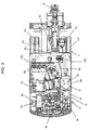
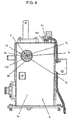
- the hydraulic oil tank 5 provided on the revolving frame 2a includes a cap 5c and a level gauge 7.
- the cap 5c is attached to an intake port 5c1 formed such that it protrudes upward from the upper side face of the hydraulic oil tank 5 and is opened upon the hydraulic oil being received and closed upon the completion of such oil being received.
- the level gauge 7 is disposed opposed to a checking hole 4a provided on one side face of the right and left side faces of the outer cover 4, which is the right-side face 13b opposed to an entrance door (not shown in the drawings) disposed on the left-side face 13a of the cab 13.
- the inside of the level gauge 7 is hollow.
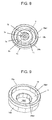
- the level gauge 7 is provided with a circular protruding portion 7a which protrudes from a side face 5a of the hydraulic oil tank 5 in order to secure the volume of the hydraulic oil tank 5, which is subject to restriction on its shape and size caused by the limited disposition space, as large as possible; and a round window 7b which is disposed on a side face 7e of the protruding portion 7a on the side of the outer cover 4 and is made from a transparent member such that the top surface of the hydraulic oil received in the hydraulic oil tank 5 can be visually checked through the oblong checking hole 4a formed on the outer cover 4 and the inside of which is provided with a star-shaped portion.
- a circular marker 7c which regulates the volume of the hydraulic oil received in the hydraulic oil tank 5 is formed.
- the hydraulic oil can be supplied to the respective actuators and the return oil from the respective actuators can be recuperated without causing any hitches during the excavation work carried out by the present small-sized hydraulic excavator (e.g. in case where an actuator is of a single rod cylinder type, there arises difference between the supplied volume and the returned volume, but it is arranged herein that the volume enough to counteract such difference can be received in the tank).
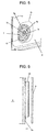
- the small-sized hydraulic excavator according to the present embodiment is provided with an attachment member 10 which is fixed to the side face 5a of the hydraulic oil tank 5 and has a circular shape surrounding the periphery of the protruding portion 7a of the level gauge 7 and is formed with such a small shape that it is included within the peripheral scope of the checking hole 4a formed on the outer cover 4 and to which the level gauge 7 is attached.
- the attachment member 10 is provided with an annular portion 10a which has a double-circle end face 10a1 on the side of the outer cover 4 and abuts to the side face 5a of the hydraulic oil tank 5 and surrounds the protruding portion 7a of the level gauge 7. Further, the attachment member 10 is provided with a retaining portion 10b which is provided continuously with the annular portion 10a and the dimension of which outside diameter is arranged smaller than the dimension of the outside diameter of the annular portion 10a and which is inserted into an insertion hole 5b formed through the hydraulic oil tank 5 and is provided with a get-through hole 10b1 with a threaded portion 102b formed therein and which retains the level gauge 7.
- the attachment member 10 is fixed to the side face 5a of the hydraulic oil tank 5 through a welded portion in the state where the retaining portion 10b is inserted into the insertion hole 5b of the hydraulic oil tank 5 and the annular portion 10a abuts to the side face 5a of the hydraulic oil tank 5.
- the level gauge 7 is provided with the above-mentioned protruding portion 7a in abutment with the retaining portion 10b of the attachment member 10 and a cylindrical insertion portion 7d which is provided continuously with the protruding portion 7a and is inserted in the get-through hole 10b1 formed on the retaining portion 10b of the attachment member 10 and on the outer circumference of which a threaded portion 7d1 to be screw-mated with the threaded portion 10b2 of the get-through hole 10b1 of the retaining portion 10b is formed.
- the insertion portion 7d of the level gauge 7 is attached to the retaining portion 10b of the attachment member 10 with the former rotationally screwed into the latter, but hereupon the window 7b provided on the protruding portion 7a of the level gauge 7 is formed into a round shape provided with a star-shaped portion inside as mentioned above, so that the unshapely impression of the window 7b can be suppressed irrespectively of the level gauge 7 being attached to the attachment member 10 at any rotational angles.
- the position of the retaining portion 10b of the attachment member 10 and the position of an attachment face 11 of the level gauge 7 forming an abutment face with the protruding portion 7a of the level gauge 7 are arranged to the further inner side of the hydraulic oil tank 5 than the side face 5a of the hydraulic oil tank 5.
- the attachment member 10 can be provided such that an end face 10a1 of the attachment member 10 on the side of the outer cover 4 is made flush with the side face 7e of the protruding portion 7a of the level gauge 7 or slightly protrudes from the side face 7e of the protruding portion 7a of the level gauge 7.
- the attachment member 10 to which the level gauge 7 is attached is formed into a shape surrounding the periphery of the protruding portion 7a of the level gauge 7 and its end face 10a1 is made flush with the side face 7e of the protruding portion 7a of the level gauge 7 or protrudes from the side face 7e of the protruding portion 7a of the level gauge 7, the annular portion 10a of the attachment member 10 receives an external force caused by the branches and twigs of the hedging trees planted in the neighboring houses upon excavation work being carried out at the housing lots where houses are lined adjacently to each other so as to suppress damage on the portions including the window 7b of the level gauge 7 susceptible to such external force.
- a highly reliable small-sized hydraulic excavator with the window 7b of the level gauge 7 protected from such external force with higher precision than the conventional counterpart is provided.
Landscapes
- Engineering & Computer Science (AREA)
- Mining & Mineral Resources (AREA)
- Civil Engineering (AREA)
- General Engineering & Computer Science (AREA)
- Structural Engineering (AREA)
- Physics & Mathematics (AREA)
- Fluid Mechanics (AREA)
- General Physics & Mathematics (AREA)
- Mechanical Engineering (AREA)
- Component Parts Of Construction Machinery (AREA)
Applications Claiming Priority (2)
| Application Number | Priority Date | Filing Date | Title |
|---|---|---|---|
| JP2016043507A JP6567993B2 (ja) | 2016-03-07 | 2016-03-07 | 小型油圧ショベル |
| PCT/JP2017/000179 WO2017154323A1 (ja) | 2016-03-07 | 2017-01-05 | 小型油圧ショベル |
Publications (3)
| Publication Number | Publication Date |
|---|---|
| EP3428347A1 EP3428347A1 (en) | 2019-01-16 |
| EP3428347A4 EP3428347A4 (en) | 2019-11-20 |
| EP3428347B1 true EP3428347B1 (en) | 2021-03-10 |
Family
ID=59789064
Family Applications (1)
| Application Number | Title | Priority Date | Filing Date |
|---|---|---|---|
| EP17762670.2A Active EP3428347B1 (en) | 2016-03-07 | 2017-01-05 | Small hydraulic shovel with level gauge for the hydraulic fluid tank |
Country Status (3)
| Country | Link |
|---|---|
| EP (1) | EP3428347B1 (enExample) |
| JP (1) | JP6567993B2 (enExample) |
| WO (1) | WO2017154323A1 (enExample) |
Families Citing this family (2)
| Publication number | Priority date | Publication date | Assignee | Title |
|---|---|---|---|---|
| JP7051631B2 (ja) * | 2018-07-20 | 2022-04-11 | 株式会社クボタ | 作業機 |
| CN114161925A (zh) * | 2021-11-30 | 2022-03-11 | 东风商用车有限公司 | 一种可观测液面的结构和油箱 |
Family Cites Families (7)
| Publication number | Priority date | Publication date | Assignee | Title |
|---|---|---|---|---|
| JPS60140843U (ja) * | 1984-02-28 | 1985-09-18 | 日本フエラス工業株式会社 | 換気装置 |
| JPS60161831U (ja) * | 1984-04-02 | 1985-10-28 | 新キャタピラー三菱株式会社 | ゲ−ジプロテクタ |
| JP2002088805A (ja) * | 2000-09-13 | 2002-03-27 | Hitachi Constr Mach Co Ltd | 油圧ショベル |
| JP4437460B2 (ja) * | 2005-05-17 | 2010-03-24 | 住友建機株式会社 | 建設機械の燃料タンク |
| JP2007090953A (ja) * | 2005-09-27 | 2007-04-12 | Ishikawajima Constr Mach Co | 作業機の燃料供給口及びカバー構造 |
| KR20080112765A (ko) * | 2007-06-22 | 2008-12-26 | 볼보 컨스트럭션 이키프먼트 홀딩 스웨덴 에이비 | 화염보호구조물을 구비한 굴삭기의 연료탱크 사이트 게이지 |
| JP5566318B2 (ja) * | 2011-02-23 | 2014-08-06 | 日立建機株式会社 | 建設機械の作動油タンク |
-
2016
- 2016-03-07 JP JP2016043507A patent/JP6567993B2/ja active Active
-
2017
- 2017-01-05 WO PCT/JP2017/000179 patent/WO2017154323A1/ja not_active Ceased
- 2017-01-05 EP EP17762670.2A patent/EP3428347B1/en active Active
Non-Patent Citations (1)
| Title |
|---|
| None * |
Also Published As
| Publication number | Publication date |
|---|---|
| JP2017160613A (ja) | 2017-09-14 |
| EP3428347A4 (en) | 2019-11-20 |
| JP6567993B2 (ja) | 2019-08-28 |
| EP3428347A1 (en) | 2019-01-16 |
| WO2017154323A1 (ja) | 2017-09-14 |
Similar Documents
| Publication | Publication Date | Title |
|---|---|---|
| CN101548048B (zh) | 轮式装载机 | |
| EP3406804B1 (en) | Compact construction machinery | |
| EP3428347B1 (en) | Small hydraulic shovel with level gauge for the hydraulic fluid tank | |
| EP1878835B1 (en) | Construction machine | |
| EP1124017B1 (en) | Hydraulically driven working machine | |
| EP2886725B1 (en) | Construction machine | |
| EP2642032A1 (en) | Construction machine swing frame | |
| WO2003084308A1 (fr) | Dispositif de levage de machine de travail pour tracteur | |
| JP6082849B2 (ja) | 作業車両、牽引装置の操作方法および牽引装置の組立方法 | |
| EP3530816B1 (en) | Hydraulic shovel | |
| JP4044314B2 (ja) | 建設機械 | |
| US7744148B2 (en) | Rotatable cab with toe guard | |
| EP3447197B1 (en) | Compact hydraulic shovel | |
| JP5054802B2 (ja) | 建設機械 | |
| KR101688499B1 (ko) | 건설기계 | |
| EP1775393A1 (en) | Protective structure for a cabin of a workmachine | |
| JP2020041369A (ja) | 建設機械 | |
| JP6898268B2 (ja) | 建設機械 | |
| JP7495854B2 (ja) | コントローラ | |
| JP4247239B2 (ja) | 掘削作業機 | |
| JP4504277B2 (ja) | 建設機械 | |
| JP7608998B2 (ja) | アダプタおよび上部旋回体 | |
| KR101144760B1 (ko) | 건설 기계 | |
| JP2002266374A (ja) | 建設機械 | |
| JP2013147893A (ja) | 作業機械及びそれが備える切換弁の配置構造 |
Legal Events
| Date | Code | Title | Description |
|---|---|---|---|
| STAA | Information on the status of an ep patent application or granted ep patent |
Free format text: STATUS: THE INTERNATIONAL PUBLICATION HAS BEEN MADE |
|
| PUAI | Public reference made under article 153(3) epc to a published international application that has entered the european phase |
Free format text: ORIGINAL CODE: 0009012 |
|
| STAA | Information on the status of an ep patent application or granted ep patent |
Free format text: STATUS: REQUEST FOR EXAMINATION WAS MADE |
|
| 17P | Request for examination filed |
Effective date: 20180326 |
|
| AK | Designated contracting states |
Kind code of ref document: A1 Designated state(s): AL AT BE BG CH CY CZ DE DK EE ES FI FR GB GR HR HU IE IS IT LI LT LU LV MC MK MT NL NO PL PT RO RS SE SI SK SM TR |
|
| AX | Request for extension of the european patent |
Extension state: BA ME |
|
| DAV | Request for validation of the european patent (deleted) | ||
| DAX | Request for extension of the european patent (deleted) | ||
| A4 | Supplementary search report drawn up and despatched |
Effective date: 20191022 |
|
| RIC1 | Information provided on ipc code assigned before grant |
Ipc: G01F 23/00 20060101ALI20191016BHEP Ipc: E02F 3/32 20060101ALI20191016BHEP Ipc: E02F 9/00 20060101AFI20191016BHEP Ipc: E02F 9/08 20060101ALI20191016BHEP Ipc: B60K 15/03 20060101ALI20191016BHEP Ipc: F15B 1/26 20060101ALI20191016BHEP |
|
| GRAP | Despatch of communication of intention to grant a patent |
Free format text: ORIGINAL CODE: EPIDOSNIGR1 |
|
| STAA | Information on the status of an ep patent application or granted ep patent |
Free format text: STATUS: GRANT OF PATENT IS INTENDED |
|
| RIC1 | Information provided on ipc code assigned before grant |
Ipc: G01F 23/00 20060101ALI20200925BHEP Ipc: E02F 9/08 20060101ALI20200925BHEP Ipc: E02F 3/32 20060101ALI20200925BHEP Ipc: E02F 9/00 20060101AFI20200925BHEP Ipc: B60K 15/03 20060101ALI20200925BHEP Ipc: G01F 23/02 20060101ALI20200925BHEP Ipc: F15B 1/26 20060101ALI20200925BHEP |
|
| INTG | Intention to grant announced |
Effective date: 20201029 |
|
| RIN1 | Information on inventor provided before grant (corrected) |
Inventor name: SUMINO, TETSUYA Inventor name: ASHIDA, TOMOAKI Inventor name: KAWAMOTO, JUNYA Inventor name: TABETA, HIROSHI |
|
| GRAS | Grant fee paid |
Free format text: ORIGINAL CODE: EPIDOSNIGR3 |
|
| GRAA | (expected) grant |
Free format text: ORIGINAL CODE: 0009210 |
|
| STAA | Information on the status of an ep patent application or granted ep patent |
Free format text: STATUS: THE PATENT HAS BEEN GRANTED |
|
| AK | Designated contracting states |
Kind code of ref document: B1 Designated state(s): AL AT BE BG CH CY CZ DE DK EE ES FI FR GB GR HR HU IE IS IT LI LT LU LV MC MK MT NL NO PL PT RO RS SE SI SK SM TR |
|
| REG | Reference to a national code |
Ref country code: GB Ref legal event code: FG4D |
|
| REG | Reference to a national code |
Ref country code: AT Ref legal event code: REF Ref document number: 1369935 Country of ref document: AT Kind code of ref document: T Effective date: 20210315 Ref country code: CH Ref legal event code: EP |
|
| REG | Reference to a national code |
Ref country code: IE Ref legal event code: FG4D |
|
| REG | Reference to a national code |
Ref country code: DE Ref legal event code: R096 Ref document number: 602017034376 Country of ref document: DE |
|
| REG | Reference to a national code |
Ref country code: LT Ref legal event code: MG9D |
|
| PG25 | Lapsed in a contracting state [announced via postgrant information from national office to epo] |
Ref country code: LT Free format text: LAPSE BECAUSE OF FAILURE TO SUBMIT A TRANSLATION OF THE DESCRIPTION OR TO PAY THE FEE WITHIN THE PRESCRIBED TIME-LIMIT Effective date: 20210310 Ref country code: BG Free format text: LAPSE BECAUSE OF FAILURE TO SUBMIT A TRANSLATION OF THE DESCRIPTION OR TO PAY THE FEE WITHIN THE PRESCRIBED TIME-LIMIT Effective date: 20210610 Ref country code: NO Free format text: LAPSE BECAUSE OF FAILURE TO SUBMIT A TRANSLATION OF THE DESCRIPTION OR TO PAY THE FEE WITHIN THE PRESCRIBED TIME-LIMIT Effective date: 20210610 Ref country code: HR Free format text: LAPSE BECAUSE OF FAILURE TO SUBMIT A TRANSLATION OF THE DESCRIPTION OR TO PAY THE FEE WITHIN THE PRESCRIBED TIME-LIMIT Effective date: 20210310 Ref country code: GR Free format text: LAPSE BECAUSE OF FAILURE TO SUBMIT A TRANSLATION OF THE DESCRIPTION OR TO PAY THE FEE WITHIN THE PRESCRIBED TIME-LIMIT Effective date: 20210611 Ref country code: FI Free format text: LAPSE BECAUSE OF FAILURE TO SUBMIT A TRANSLATION OF THE DESCRIPTION OR TO PAY THE FEE WITHIN THE PRESCRIBED TIME-LIMIT Effective date: 20210310 |
|
| REG | Reference to a national code |
Ref country code: AT Ref legal event code: MK05 Ref document number: 1369935 Country of ref document: AT Kind code of ref document: T Effective date: 20210310 |
|
| REG | Reference to a national code |
Ref country code: NL Ref legal event code: MP Effective date: 20210310 |
|
| PG25 | Lapsed in a contracting state [announced via postgrant information from national office to epo] |
Ref country code: LV Free format text: LAPSE BECAUSE OF FAILURE TO SUBMIT A TRANSLATION OF THE DESCRIPTION OR TO PAY THE FEE WITHIN THE PRESCRIBED TIME-LIMIT Effective date: 20210310 Ref country code: RS Free format text: LAPSE BECAUSE OF FAILURE TO SUBMIT A TRANSLATION OF THE DESCRIPTION OR TO PAY THE FEE WITHIN THE PRESCRIBED TIME-LIMIT Effective date: 20210310 Ref country code: SE Free format text: LAPSE BECAUSE OF FAILURE TO SUBMIT A TRANSLATION OF THE DESCRIPTION OR TO PAY THE FEE WITHIN THE PRESCRIBED TIME-LIMIT Effective date: 20210310 |
|
| PG25 | Lapsed in a contracting state [announced via postgrant information from national office to epo] |
Ref country code: NL Free format text: LAPSE BECAUSE OF FAILURE TO SUBMIT A TRANSLATION OF THE DESCRIPTION OR TO PAY THE FEE WITHIN THE PRESCRIBED TIME-LIMIT Effective date: 20210310 |
|
| PG25 | Lapsed in a contracting state [announced via postgrant information from national office to epo] |
Ref country code: CZ Free format text: LAPSE BECAUSE OF FAILURE TO SUBMIT A TRANSLATION OF THE DESCRIPTION OR TO PAY THE FEE WITHIN THE PRESCRIBED TIME-LIMIT Effective date: 20210310 Ref country code: EE Free format text: LAPSE BECAUSE OF FAILURE TO SUBMIT A TRANSLATION OF THE DESCRIPTION OR TO PAY THE FEE WITHIN THE PRESCRIBED TIME-LIMIT Effective date: 20210310 Ref country code: AT Free format text: LAPSE BECAUSE OF FAILURE TO SUBMIT A TRANSLATION OF THE DESCRIPTION OR TO PAY THE FEE WITHIN THE PRESCRIBED TIME-LIMIT Effective date: 20210310 Ref country code: SM Free format text: LAPSE BECAUSE OF FAILURE TO SUBMIT A TRANSLATION OF THE DESCRIPTION OR TO PAY THE FEE WITHIN THE PRESCRIBED TIME-LIMIT Effective date: 20210310 |
|
| PG25 | Lapsed in a contracting state [announced via postgrant information from national office to epo] |
Ref country code: IS Free format text: LAPSE BECAUSE OF FAILURE TO SUBMIT A TRANSLATION OF THE DESCRIPTION OR TO PAY THE FEE WITHIN THE PRESCRIBED TIME-LIMIT Effective date: 20210710 Ref country code: PT Free format text: LAPSE BECAUSE OF FAILURE TO SUBMIT A TRANSLATION OF THE DESCRIPTION OR TO PAY THE FEE WITHIN THE PRESCRIBED TIME-LIMIT Effective date: 20210712 Ref country code: PL Free format text: LAPSE BECAUSE OF FAILURE TO SUBMIT A TRANSLATION OF THE DESCRIPTION OR TO PAY THE FEE WITHIN THE PRESCRIBED TIME-LIMIT Effective date: 20210310 Ref country code: RO Free format text: LAPSE BECAUSE OF FAILURE TO SUBMIT A TRANSLATION OF THE DESCRIPTION OR TO PAY THE FEE WITHIN THE PRESCRIBED TIME-LIMIT Effective date: 20210310 Ref country code: SK Free format text: LAPSE BECAUSE OF FAILURE TO SUBMIT A TRANSLATION OF THE DESCRIPTION OR TO PAY THE FEE WITHIN THE PRESCRIBED TIME-LIMIT Effective date: 20210310 |
|
| REG | Reference to a national code |
Ref country code: DE Ref legal event code: R097 Ref document number: 602017034376 Country of ref document: DE |
|
| PLBE | No opposition filed within time limit |
Free format text: ORIGINAL CODE: 0009261 |
|
| STAA | Information on the status of an ep patent application or granted ep patent |
Free format text: STATUS: NO OPPOSITION FILED WITHIN TIME LIMIT |
|
| PG25 | Lapsed in a contracting state [announced via postgrant information from national office to epo] |
Ref country code: ES Free format text: LAPSE BECAUSE OF FAILURE TO SUBMIT A TRANSLATION OF THE DESCRIPTION OR TO PAY THE FEE WITHIN THE PRESCRIBED TIME-LIMIT Effective date: 20210310 Ref country code: DK Free format text: LAPSE BECAUSE OF FAILURE TO SUBMIT A TRANSLATION OF THE DESCRIPTION OR TO PAY THE FEE WITHIN THE PRESCRIBED TIME-LIMIT Effective date: 20210310 Ref country code: AL Free format text: LAPSE BECAUSE OF FAILURE TO SUBMIT A TRANSLATION OF THE DESCRIPTION OR TO PAY THE FEE WITHIN THE PRESCRIBED TIME-LIMIT Effective date: 20210310 |
|
| 26N | No opposition filed |
Effective date: 20211213 |
|
| PG25 | Lapsed in a contracting state [announced via postgrant information from national office to epo] |
Ref country code: SI Free format text: LAPSE BECAUSE OF FAILURE TO SUBMIT A TRANSLATION OF THE DESCRIPTION OR TO PAY THE FEE WITHIN THE PRESCRIBED TIME-LIMIT Effective date: 20210310 |
|
| PG25 | Lapsed in a contracting state [announced via postgrant information from national office to epo] |
Ref country code: IT Free format text: LAPSE BECAUSE OF FAILURE TO SUBMIT A TRANSLATION OF THE DESCRIPTION OR TO PAY THE FEE WITHIN THE PRESCRIBED TIME-LIMIT Effective date: 20210310 |
|
| PG25 | Lapsed in a contracting state [announced via postgrant information from national office to epo] |
Ref country code: IS Free format text: LAPSE BECAUSE OF FAILURE TO SUBMIT A TRANSLATION OF THE DESCRIPTION OR TO PAY THE FEE WITHIN THE PRESCRIBED TIME-LIMIT Effective date: 20210710 |
|
| PG25 | Lapsed in a contracting state [announced via postgrant information from national office to epo] |
Ref country code: MC Free format text: LAPSE BECAUSE OF FAILURE TO SUBMIT A TRANSLATION OF THE DESCRIPTION OR TO PAY THE FEE WITHIN THE PRESCRIBED TIME-LIMIT Effective date: 20210310 |
|
| REG | Reference to a national code |
Ref country code: CH Ref legal event code: PL |
|
| REG | Reference to a national code |
Ref country code: BE Ref legal event code: MM Effective date: 20220131 |
|
| PG25 | Lapsed in a contracting state [announced via postgrant information from national office to epo] |
Ref country code: LU Free format text: LAPSE BECAUSE OF NON-PAYMENT OF DUE FEES Effective date: 20220105 |
|
| PG25 | Lapsed in a contracting state [announced via postgrant information from national office to epo] |
Ref country code: BE Free format text: LAPSE BECAUSE OF NON-PAYMENT OF DUE FEES Effective date: 20220131 |
|
| PG25 | Lapsed in a contracting state [announced via postgrant information from national office to epo] |
Ref country code: LI Free format text: LAPSE BECAUSE OF NON-PAYMENT OF DUE FEES Effective date: 20220131 Ref country code: CH Free format text: LAPSE BECAUSE OF NON-PAYMENT OF DUE FEES Effective date: 20220131 |
|
| PG25 | Lapsed in a contracting state [announced via postgrant information from national office to epo] |
Ref country code: IE Free format text: LAPSE BECAUSE OF NON-PAYMENT OF DUE FEES Effective date: 20220105 |
|
| PG25 | Lapsed in a contracting state [announced via postgrant information from national office to epo] |
Ref country code: HU Free format text: LAPSE BECAUSE OF FAILURE TO SUBMIT A TRANSLATION OF THE DESCRIPTION OR TO PAY THE FEE WITHIN THE PRESCRIBED TIME-LIMIT; INVALID AB INITIO Effective date: 20170105 |
|
| PG25 | Lapsed in a contracting state [announced via postgrant information from national office to epo] |
Ref country code: MK Free format text: LAPSE BECAUSE OF FAILURE TO SUBMIT A TRANSLATION OF THE DESCRIPTION OR TO PAY THE FEE WITHIN THE PRESCRIBED TIME-LIMIT Effective date: 20210310 Ref country code: CY Free format text: LAPSE BECAUSE OF FAILURE TO SUBMIT A TRANSLATION OF THE DESCRIPTION OR TO PAY THE FEE WITHIN THE PRESCRIBED TIME-LIMIT Effective date: 20210310 |
|
| PG25 | Lapsed in a contracting state [announced via postgrant information from national office to epo] |
Ref country code: MT Free format text: LAPSE BECAUSE OF FAILURE TO SUBMIT A TRANSLATION OF THE DESCRIPTION OR TO PAY THE FEE WITHIN THE PRESCRIBED TIME-LIMIT Effective date: 20210310 |
|
| PGFP | Annual fee paid to national office [announced via postgrant information from national office to epo] |
Ref country code: GB Payment date: 20241128 Year of fee payment: 9 |
|
| PGFP | Annual fee paid to national office [announced via postgrant information from national office to epo] |
Ref country code: FR Payment date: 20241209 Year of fee payment: 9 |
|
| PGFP | Annual fee paid to national office [announced via postgrant information from national office to epo] |
Ref country code: DE Payment date: 20241203 Year of fee payment: 9 |