EP3424691A1 - Vorrichtung zum transport und zum wahlweisen vorvernetzen einer aus einer kautschukmischung extrudierten materialbahn - Google Patents
Vorrichtung zum transport und zum wahlweisen vorvernetzen einer aus einer kautschukmischung extrudierten materialbahn Download PDFInfo
- Publication number
- EP3424691A1 EP3424691A1 EP18163514.5A EP18163514A EP3424691A1 EP 3424691 A1 EP3424691 A1 EP 3424691A1 EP 18163514 A EP18163514 A EP 18163514A EP 3424691 A1 EP3424691 A1 EP 3424691A1
- Authority
- EP
- European Patent Office
- Prior art keywords
- irradiation chamber
- conveyor
- belt
- bypass
- conveyor belt
- Prior art date
- Legal status (The legal status is an assumption and is not a legal conclusion. Google has not performed a legal analysis and makes no representation as to the accuracy of the status listed.)
- Granted
Links
Images

Classifications
-
- B—PERFORMING OPERATIONS; TRANSPORTING
- B29—WORKING OF PLASTICS; WORKING OF SUBSTANCES IN A PLASTIC STATE IN GENERAL
- B29D—PRODUCING PARTICULAR ARTICLES FROM PLASTICS OR FROM SUBSTANCES IN A PLASTIC STATE
- B29D30/00—Producing pneumatic or solid tyres or parts thereof
- B29D30/0016—Handling tyres or parts thereof, e.g. supplying, storing, conveying
-
- B—PERFORMING OPERATIONS; TRANSPORTING
- B29—WORKING OF PLASTICS; WORKING OF SUBSTANCES IN A PLASTIC STATE IN GENERAL
- B29D—PRODUCING PARTICULAR ARTICLES FROM PLASTICS OR FROM SUBSTANCES IN A PLASTIC STATE
- B29D30/00—Producing pneumatic or solid tyres or parts thereof
- B29D30/0005—Pretreatment of tyres or parts thereof, e.g. preheating, irradiation, precuring
-
- B—PERFORMING OPERATIONS; TRANSPORTING
- B29—WORKING OF PLASTICS; WORKING OF SUBSTANCES IN A PLASTIC STATE IN GENERAL
- B29D—PRODUCING PARTICULAR ARTICLES FROM PLASTICS OR FROM SUBSTANCES IN A PLASTIC STATE
- B29D30/00—Producing pneumatic or solid tyres or parts thereof
- B29D30/0005—Pretreatment of tyres or parts thereof, e.g. preheating, irradiation, precuring
- B29D2030/0011—Surface activation of tyres or parts thereof, e.g. by plasma treatment
-
- B—PERFORMING OPERATIONS; TRANSPORTING
- B29—WORKING OF PLASTICS; WORKING OF SUBSTANCES IN A PLASTIC STATE IN GENERAL
- B29D—PRODUCING PARTICULAR ARTICLES FROM PLASTICS OR FROM SUBSTANCES IN A PLASTIC STATE
- B29D30/00—Producing pneumatic or solid tyres or parts thereof
- B29D30/0016—Handling tyres or parts thereof, e.g. supplying, storing, conveying
- B29D2030/0022—Handling green tyres, e.g. transferring or storing between tyre manufacturing steps
Definitions
- the invention relates to a device for transporting and optionally pre-crosslinking a material web extruded from a rubber mixture.
- the invention is therefore based on the object to be able to incorporate an irradiation chamber in an extruder line such that production losses caused by maintenance work are avoided.
- the device according to the invention also eliminates the need for any "offline irradiation", ie external irradiation, in which the extruded material web first has to be packed and then transported to the electron beam source.
- a pre-crosslinked immediately after extrusion material web can be wound without adhesion and dimensionally stable on a spool for intermediate storage, the coils can also be transported easily advantageously.
- the conveyor belt is a chain conveyor belt consisting in particular of stainless steel.
- Such a conveyor belt is resistant to electron radiation and also particularly resistant to wear.
- the continuous belt preferably has a return strand recirculated below the irradiation chamber. It is therefore carried out only the Lasttrum of the continuous belt through the irradiation chamber, which is in terms of required radiation protection measures of advantage.
- the continuous belt has an empty strand which is returned to the irradiation chamber.
- the feed device is pivotable about an axis which coincides with the axis of rotation of a deflection roller of a transport device directly following the feed device.
- the removal device is pivotable about an axis which coincides with the axis of rotation of a deflection roller of a transport device immediately following the removal device.
- the pivotable removal device and the pivotable feeder can be arranged and operated in a particularly simple manner when the conveyor belt and the bypass conveyor extend in side view parallel to each other and in the vertical direction übereander. In this context, it is also advantageous if the conveyor belt and the bypass conveyor laterally project beyond the irradiation chamber to a consistent extent.
- the feed device, the bypass conveyor and the removal device preferably each have a conveyor belt or a chain conveyor belt or are preferably roller conveyors.
- a housing-like protective cover adjoins the irradiation chamber on both sides.
- the protective covers are used in particular for personal protection.
- each protective cover has stationary cover parts directly adjoining the irradiation chamber and a cover part which can be pivoted together with the feed device or the removal device.
- a curved cover wall is preferably arranged, which at the Bypass conveyor pivoted feeder or covered in the bypass conveyor Abtransport boots covers the stationary cover.
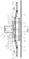
- the device comprises an irradiation device 1 and a transport device.
- the irradiation device 1 is arranged on supports 3 resting on the substrate 2 and has an irradiation chamber 1 'and a chamber 1 "mounted thereon.
- an electron beam source 4 projecting into the irradiation chamber 1' for precrosslinking of rubber mixtures is positioned which has an irradiation window 4a located within the irradiation chamber 1 '.
- the irradiation chamber 1 ' is designed to be elongated parallel to the substrate 2 and has a bottom 1a, a ceiling 1b, at their end faces in each case a perpendicular to the substrate 2 oriented end wall 1c and more in Fig. 1 unseen elongate sidewalls. In each end wall 1c, a horizontal slot 5 is formed at the lower portion.
- the transport device comprises a conveyor belt 6, a bypass belt 7, a feed belt 8 and a removal belt 9 and in the embodiment shown, further conveyor belts 8 ', 9'.
- Each of these belts 6, 7, 8, 8 ', 9, 9' is arranged circumferentially on two deflecting rollers 10 indicated in the figures, one of the deflecting rollers 10 being driven in a known manner.
- the transport direction is in Fig. 1 and Fig. 2 each marked by two arrow P 1 .
- the continuous belt 6 is preferably a chain conveyor belt consisting in particular of stainless steel.
- the bypass belt 7, the feed belt 8, the removal belt 9 and the other conveyor belts 8 ', 9' may also be chain conveyor belts.
- the bypass belt 7, the feed belt 8, the removal belt 9 and the further conveyor belts 8 ', 9' may also be roller conveyors.
- the continuous belt 6 is arranged on the irradiation chamber 1 ', wherein the deflection rollers 10 of the continuous belt 6 are positioned outside of the irradiation chamber 1' next to the slots 5.
- the load strand 6a of the continuous belt 6 is passed through the irradiation chamber 1 ', the slack side 6b of the continuous belt 6 in the embodiment shown below and thus outside of the irradiation chamber 1', but may alternatively also be passed through the irradiation chamber 1 '.
- the load strand 6a is further deflected within the irradiation chamber 1 'via deflection devices (not shown), for example rollers, sprockets or the like, in such a way that it has two inclined load strand sections 6'a in longitudinal section, each rising from one of the end walls 1c to the electron beam source 4, and A load-carrying section 6 "a extending horizontally just below the irradiation window 4a as well as between the inclined load-rail sections 6'a has a plate-shaped electron catcher 11 arranged directly underneath the horizontally extending load-carrying section 6" a, which is in particular a water-cooled stainless steel body.
- irradiation chamber 1 ' Within the irradiation chamber 1 'are arranged in the region of the inclined Lasttrumabête 6'a of the ceiling 1b and from the bottom 1a of the irradiation chamber 1' vertically projecting plates 12, wherein between the free ends of the Ceiling 1b protruding plates 12 and the free ends of the protruding from the bottom of the plate 1a plates 12 is a free space through which the inclined Lasttrumabête 6 'a performed.
- the plates 12 consist in particular of lead and serve to shield the X-radiation, which is generated during the deceleration of the electrons ("bremsstrahlung"), so that it is ensured that X-radiation reaches at most a small dose below a predetermined limit via the slits 5 from the irradiation chamber 1 'escape.
- three to five, in the embodiment shown, three plates 12 are arranged in the region of each inclined Lasttrumabêtes 6'a on the ceiling 1b and the bottom 1a.
- the bypass belt 7 extends below the irradiation chamber 1 'and substantially horizontally and parallel to the conveyor belt 6, wherein the deflection rollers 10 of the bypass belt 7 are perpendicular below the guide rollers 10 of the continuous belt 6, so that the pass belt 6 and the bypass belt. 7 project over the irradiation chamber 1 'laterally to a consistent extent.
- the conveyor belt 8 'and the feed belt 8 are arranged one behind the other and are, in relation to the transport direction, in front of the continuous belt 6 and the bypass belt 7, wherein the feed belt 8 between the conveyor belt 8' and the conveyor belt 6 and the bypass belt 7 is arranged.
- the feed belt 8 is pivotally mounted in the region of its end lying at the conveyor belt 8 ', so that its other, free end is pivotable in a position to the left end of the continuous belt 6 and in a position to the left end of the bypass belt 7.
- the pivot axis of the feed belt 8 coincides with the axis of rotation of the right deflection roller 10 of the conveyor belt 8 '.
- the conveyor belt 9 'and the removal belt 9 are also arranged one behind the other and are located, with respect to the transport direction, behind the conveyor belt 6 and the bypass belt 7, wherein the discharge conveyor 9 between the conveyor belt 9' and the conveyor belt 6 or the bypass belt.
- Band 7 is arranged.
- the removal belt 9 is pivotally mounted in the region of his at the conveyor belt 9 'lying end, so that his other, free end in a position to the right end of the continuous belt 6 and in a Position to the right end of the bypass belt 7 is pivotable.
- the pivot axis of the discharge conveyor 9 coincides with the axis of rotation of the left guide roller 10 of the conveyor belt 9 'together.
- Each protective cover 13 has a lower stationary cover part 13a, an upper stationary cover part 13b mounted thereon, and a pivotable cover part 13c.
- the upper stationary cover parts 13b adjoin the end walls 1c and surround the end section of the continuous belt 6 located outside the irradiation chamber 1 '.
- the lower stationary cover parts 13a surround the two end sections of the bypass belt 7 projecting beyond the irradiation chamber 1'
- Stationary Abdeckteilmaschine 13a and 13b have on the conveyor belt 8 and the removal belt 9 on an inwardly curved contour, which, viewed in section, is rounded along a radius.
- the center of the radius underlying the circle is located on the corresponding and already mentioned pivot axis of the feed belt 8 and the Abtransportbandes 9.
- the left pivotable cover 13c surrounds the feed belt 8 and the right pivoting cover 13c surrounds the discharge conveyor 9.
- a curved cover wall 13d is placed on the edge of the pivotable cover part 13c facing the stationary cover parts 13a, 13b.
- the pivotable cover part 13c and the cover wall 13d are curved outward such that their curvature corresponds to the curvature of the two stationary cover parts 13a, 13b.
- the left pivoting cover 13c extends behind the feed roller 8 located on the deflection roller 10 of the conveyor belt 8 'and the right pivotable cover 13c extends behind lying on the conveyor belt 9 guide roller 10 of the conveyor belt 9'.
- Fig. 1 the supply belt 8 and the discharge belt 9 are pivoted to the pass belt 6, so that the pivotable cover members 13c connect to the respective upper stationary cover member 13b and the curved cover walls 13d on the protrude upper stationary cover 13b.
- a material web 14 extruded from a rubber mixture is passed through the irradiation chamber 1 'and pre-crosslinked therein by the electron beam of the electron beam source 4.
- pre-crosslinking material webs 14 for example, are provided, from which subsequently side walls, treads or inner layers are formed for pneumatic vehicle tires.
- Fig. 2 the supply belt 8 and the discharge belt 9 are pivoted to the bypass belt 7, so that the pivotable cover parts 13c connect to the respective lower stationary cover part 13b and the curved cover walls 13d close the upper stationary cover parts 13b.
- the material web 14 is guided past the bypass belt 7 on the irradiation chamber 1 'and therefore not irradiated.
Landscapes
- Engineering & Computer Science (AREA)
- Mechanical Engineering (AREA)
- Heating, Cooling, Or Curing Plastics Or The Like In General (AREA)
Abstract
Description
- Die Erfindung betrifft eine Vorrichtung zum Transport und zum wahlweisen Vorvernetzen einer aus einer Kautschukmischung extrudierten Materialbahn.
- Bei der Reifenherstellung ist es bekannt, aus Kautschukmischungen extrudierte Materialbahnen in Bestrahlungskammern zu transportieren und diese dort mittels Elektronenstrahlen oberflächlich vorzuvernetzen. Die vorvernetzten Materialbahnen weisen gegenüber den aus "rohen" Kautschukmischungen bestehenden Materialbahnen eine reduzierte Klebrigkeit auf und eignen sich zum Aufwickeln auf Wickelspulen zur Zwischenlagerung. Nach dem Zuschneiden der Materialbahnen werden aus diesen entsprechende Reifenbauteile gebildet bzw. aufgebaut.
- Eine Vorvernetzung von extrudierten Materialbahnen ist jedoch nicht bei allen Materialbahnen vorgesehen und erforderlich. Ist eine Vorvernetzung vorteilhaft, ergibt sich in der Praxis oft das Problem, dass das Betreiben von Bestrahlungskammern mit einem relativ hohen Wartungsaufwand verbunden ist. Das an und für sich vorteilhafte Einbinden von Bestrahlungskammern im Wesentlichen unmittelbar nach der Extrusion in die Extruderlinie ist daher problematisch, da die erforderliche Wartung der Kammern mit Produktionsausfällen verbunden ist.
- Der Erfindung liegt daher die Aufgabe zu Grunde, eine Bestrahlungskammer derart in eine Extruderlinie einzubinden zu können, dass durch Wartungsarbeiten bedingte Produktionsausfälle vermieden werden.
- Gelöst wird die gestellte Aufgabe erfindungsgemäß mit einer Vorrichtung umfassend:
- eine Bestrahlungskammer mit einer Elektronenstrahlquelle,
- ein an der Bestrahlungskammer angeordnetes Durchlaufband mit einem durch die Bestrahlungskammer hindurchgeführten Lasttrum,
- einen unterhalb der Bestrahlungskammer angeordneter Bypass-Förderer,
- eine bezogen auf die Transportrichtung vor der Bestrahlungskammer angeordnete Zuführeinrichtung, welche in eine zum Durchlaufband führende Position und in eine zum Bypass-Förderer führende Position schwenkbar ist und
- eine bezogen auf die Transportrichtung hinter der Bestrahlungskammer angeordnete Abtransporteinrichtung, welche in eine zum Durchlaufband führende Position und in eine zum Bypass-Förderer führende Position schwenkbar ist.
- Bei einer erfindungsgemäßen Vorrichtung besteht durch die der Bestrahlungskammer vorgeordnete schwenkbare Zuführeinrichtung und die der Bestrahlungskammer nachgeordnete schwenkbare Abtransporteinrichtung die Möglichkeit, die extrudierte Materialbahn über den Bypass-Förderer an der Bestrahlungskammer vorbeizuführen. Ist eine Wartung der Bestrahlungskammer erforderlich, braucht die Extrusion nicht unterbrochen zu werden. Insbesondere kann während der Wartungsarbeiten auch eine nicht zur Vorvernetzung vorgesehene Materialbahn extrudiert werden. Es kann auch vorgesehen sein, die Materialbahn über den Bypass-Förderer zu einer zweiten Bestrahlungskammer umzuleiten. Durch die erfindungsgemäße Vorrichtung entfällt ferner die Notwendigkeit einer etwaigen "Offlinebestrahlung", also einer externen Bestrahlung, bei welcher die extrudierte Materialbahn zuerst verpackt und dann zur Elektronenstrahlquelle transportiert werden muss. Eine unmittelbar nach der Extrusion vorvernetzte Materialbahn kann zur Zwischenlagerung haftungsfrei und formstabil auf eine Spule aufgewickelt werden, wobei die Spulen vorteilhafter Weise auch einfach transportiert werden können.
- Gemäß einer bevorzugten Ausführungsvariante ist das Durchlaufband ein insbesondere aus Edelstahl bestehendes Kettenförderband. Ein solches Durchlaufband ist gegenüber Elektronenstrahlung beständig und ferner besonders verschleißresistent.
- Bevorzugter Weise weist das Durchlaufband ein unterhalb der Bestrahlungskammer rückgeführtes Leertrum auf. Es ist daher lediglich das Lasttrum des Durchlaufbandes durch die Bestrahlungskammer durchgeführt, was im Hinblick auf erforderliche Strahlenschutzmaßnahmen von Vorteil ist. Gemäß einer alternativen Ausführungsvariante weist das Durchlaufband ein in der die Bestrahlungskammer rückgeführtes Leertrum auf.
- Gemäß einer weiteren bevorzugten Ausführungsvariante ist die Zuführeinrichtung um eine Achse, welche mit der Drehachse einer Umlenkrolle einer unmittelbar an die Zuführeinrichtung anschließenden Transporteinrichtung zusammenfällt, schwenkbar. Auf analoge Weise ist die Abtransporteinrichtung um eine Achse, welche mit der Drehachse einer Umlenkrolle einer unmittelbar an die Abtransporteinrichtung anschließenden Transporteinrichtung zusammenfällt, schwenkbar.
- Die schwenkbare Abtransporteinrichtung sowie die schwenkbare Zuführeinrichtung lassen sich auf besonders einfache Weise anordnen und betätigen, wenn sich das Durchlaufband und der Bypass-Förderer in Seitenansicht parallel zueinander und in vertikaler Richtung übereiander erstrecken. In diesem Zusammenhang ist es ferner von Vorteil, wenn das Durchlaufband und der Bypass-Förderer die Bestrahlungskammer seitlich in übereinstimmendem Ausmaß überragen.
- Die Zuführeinrichtung, der Bypass-Förderer und die Abtransporteinrichtung weisen bevorzugter Weise jeweils ein Transportband oder ein Kettenförderband auf oder sind in bevorzugter Weise Rollenförderer.
- Gemäß einer weiteren bevorzugten Ausführungsvariante schließt an die Bestrahlungskammer beidseitig jeweils eine gehäuseartige Schutzabdeckung an. Die Schutzabdeckungen dienen insbesondere dem Personenschutz. Bevorzugter Weise weist jede Schutzabdeckung unmittelbar an die Bestrahlungskammer anschließende stationäre Abdeckteile und einen gemeinsam mit der Zuführeinrichtung bzw. der Abtransporteinrichtung schwenkbaren Abdeckteil auf. An der Oberseite des schwenkbaren Abdeckteiles ist vorzugsweise eine gebogene Abdeckwand angeordnet, welche bei zum Bypass-Förderer geschwenkter Zuführeinrichtung bzw. bei zum Bypass-Förderer geschwenkter Abtransporteinrichtung den stationären Abdeckteil abdeckt.
- Weitere Merkmale, Vorteile und Einzelheiten der Erfindung werden nun anhand der Zeichnung, die schematisch ein Ausführungsbeispiel der Erfindung darstellt, näher beschrieben. Dabei zeigen
-
Fig. 1 eine schematische seitliche Schnittansicht einer Vorrichtung gemäß einer Ausführungsvariante der Erfindung in einem ersten Betriebszustand und -
Fig. 2 eine schematische seitliche Schnittansicht der Vorrichtung ausFig. 1 in einem zweiten Betriebszustand. - In der nachfolgenden Beschreibung verwendete Richtungsangaben beziehen sich, falls nicht anders erwähnt, auf die Lage der einzelnen Bauteile der Vorrichtung wie in den Figuren gezeigt.
- Wie
Fig. 1 undFig. 2 zeigen, umfasst die Vorrichtung eine Bestrahlungseinrichtung 1 und eine Transportvorrichtung. - Die Bestrahlungseinrichtung 1 ist auf am Untergrund 2 aufstehenden Stützen 3 angeordnet und weist eine Bestrahlungskammer 1' und eine auf diese aufgesetzte Kammer 1" auf. In der aufgesetzten Kammer 1" ist eine in die Bestrahlungskammer 1' hineinragende zur Vorvernetzung von Kautschukmischungen geeignete Elektronenstrahlquelle 4 positioniert, welche ein innerhalb der Bestrahlungskammer 1' befindliches Bestrahlungsfenster 4a aufweist. Die Bestrahlungskammer 1' ist parallel zum Untergrund 2 langgestreckt ausgeführt und weist einen Boden 1a, eine Decke 1b, an ihren Stirnseiten jeweils eine senkrecht zum Untergrund 2 orientierte Stirnwand 1c sowie weitere in
Fig. 1 nicht zu sehende langgestreckte Seitenwände auf. In jeder Stirnwand 1c ist am unteren Bereich ein waagrechter Schlitz 5 ausgebildet. - Die Transportvorrichtung umfasst ein Durchlaufband 6, ein Bypass-Band 7, ein Zuführband 8 und ein Abtransportband 9 sowie beim gezeigten Ausführungsbeispiel weitere Transportbänder 8', 9'. Jedes dieser Bänder 6, 7, 8, 8', 9, 9' ist an zwei in den Figuren angedeuteten Umlenkrollen 10 umlaufend angeordnet, wobei jeweils eine der Umlenkrollen 10 in bekannter Weise angetrieben ist. Die Transportrichtung ist in
Fig. 1 undFig. 2 jeweils durch zwei Pfeil P1 gekennzeichnet. - Das Durchlaufband 6 ist bevorzugter Weise ein insbesondere aus rostfreiem Edelstahl bestehendes Kettenförderband. Das Bypass-Band 7, das Zuführband 8, das Abtransportband 9 sowie die weiteren Transportbänder 8', 9' können ebenfalls Kettenförderbänder sein. Das Bypass-Band 7, das Zuführband 8, das Abtransportbandes 9 und die weiteren Transportbänder 8', 9' können auch Rollenförderer sein.
- Das Durchlaufband 6 ist an der Bestrahlungskammer 1' angeordnet, wobei die Umlenkrollen 10 des Durchlaufbandes 6 außerhalb der Bestrahlungskammer 1' neben den Schlitzen 5 positioniert sind. Das Lasttrum 6a des Durchlaufbandes 6 ist durch die Bestrahlungskammer 1' hindurchgeführt, das Leertrum 6b des Durchlaufbandes 6 verläuft beim gezeigten Ausführungsbeispiel unterhalb und damit außerhalb der Bestrahlungskammer 1', kann alternativ jedoch ebenfalls durch die Bestrahlungskammer 1' hindurchgeführt sein. Das Lasttrum 6a ist ferner innerhalb der Bestrahlungskammer 1' derart über nicht gezeigte Umlenkeinrichtungen, beispielsweise Rollen, Kettenräder oder dergleichen, umgelenkt, dass es im Längsschnitt zwei geneigte Lasttrumabschnitte 6'a aufweist, die jeweils von einer der Stirnwände 1c zur Elektronenstrahlquelle 4 ansteigen, und einen knapp unterhalb des Bestrahlungsfensters 4a sowie zwischen den geneigten Lasttrumabschnitten 6'a waagrecht verlaufenden Lasttrumabschnitt 6"a besitzt. Unmittelbar unterhalb des waagrecht verlaufenden Lasttrumabschnittes 6"a ist ein plattenförmiger Elektronenfänger 11 angeordnet, welcher insbesondere ein wassergekühlter Edelstahlkörper ist.
- Innerhalb der Bestrahlungskammer 1' sind im Bereich der geneigten Lasttrumabschnitte 6'a von der Decke 1b und vom Boden 1a der Bestrahlungskammer 1' senkrecht abstehende Platten 12 angeordnet, wobei zwischen den freien Enden der von der Decke 1b abstehenden Platten 12 und den freien Enden der vom Boden 1a abstehenden Platten 12 ein Freiraum besteht, durch welchen die geneigte Lasttrumabschnitte 6'a durchgeführt sind. Die Platten 12 bestehen insbesondere aus Blei und dienen zur Abschirmung von Röntgenstrahlung, welche bei der Abbremsung der Elektronen entsteht ("Bremsstrahlung"), sodass sichergestellt ist, dass Röntgenstrahlung höchstens in geringer, unter vorgegebenem Grenzwert liegender Dosis über die Schlitze 5 aus der Bestrahlungskammer 1' entweichen kann. Bevorzugter Weise sind im Bereich jedes geneigten Lasttrumabschnittes 6'a an der Decke 1b und am Boden 1a jeweils drei bis fünf, beim gezeigten Ausführungsbeispiel drei, Platten 12 angeordnet.
- Das Bypass-Band 7 verläuft unterhalb der Bestrahlungskammer 1' sowie im Wesentlichen waagrecht und parallel zum Durchlaufband 6, wobei die Umlenkrollen 10 des Bypass-Bandes 7 senkrecht unterhalb der Umlenkrollen 10 des Durchlaufbandes 6 liegen, sodass das Durchlaufband 6 und das Bypass-Band 7 die Bestrahlungskammer 1' seitlich in übereinstimmendem Ausmaß überragen.
- Das Transportband 8' und das Zuführband 8 sind hintereinander angeordnet und befinden sich, bezogen auf die Transportrichtung, vor dem Durchlaufband 6 und dem Bypass-Band 7, wobei das Zuführband 8 zwischen dem Transportband 8' und dem Durchlaufband 6 bzw. dem Bypass-Band 7 angeordnet ist. Das Zuführband 8 ist im Bereich seines beim Transportband 8' liegenden Endes schwenkbar gelagert, sodass sein anderes, freies Ende in eine Position zum linken Ende des Durchlaufbandes 6 und in eine Position zum linken Ende des Bypass-Bandes 7 schwenkbar ist. Beim gezeigten Ausführungsbeispiel fällt die Schwenkachse des Zuführbandes 8 mit der Drehachse der rechten Umlenkrolle 10 des Transportbandes 8' zusammen.
- Das Transportband 9' und das Abtransportband 9 sind ebenfalls hintereinander angeordnet und befinden sich, bezogen auf die Transportrichtung, hinter dem Durchlaufband 6 und dem Bypass-Band 7, wobei das Abtransportband 9 zwischen dem Transportband 9' und dem Durchlaufband 6 bzw. dem Bypass-Band 7 angeordnet ist. Das Abtransportband 9 ist im Bereich seines beim Transportband 9' liegenden Endes schwenkbar gelagert, sodass sein anderes, freies Ende in eine Position zum rechten Ende des Durchlaufbandes 6 und in eine Position zum rechten Ende des Bypass-Bandes 7 schwenkbar ist. Beim gezeigten Ausführungsbeispiel fällt die Schwenkachse des Abtransportbandes 9 mit der Drehachse der linken Umlenkrolle 10 des Transportbandes 9' zusammen.
- An den Stirnwänden 1c der Bestrahlungskammer 1' schließt jeweils eine mehrteilige gehäuseartige Schutzabdeckung 13 an. Jede Schutzabdeckung 13 weist einen unteren stationären Abdeckteil 13a, einen auf diesem aufgesetzten oberen stationären Abdeckteil 13b, sowie einen schwenkbaren Abdeckteil 13c auf. Die oberen stationären Abdeckteile 13b grenzen an die Stirnwände 1c an und umgeben den außerhalb der Bestrahlungskammer 1' befindlichen Endabschnitt des Durchlaufbandes 6. Die unteren stationären Abdeckteile 13a umgeben die beiden über die Bestrahlungskammer 1' hinausragenden Endabschnitte des Bypass-Bandes 7. Die jeweils aufeinander angeordneten stationären Abdeckteilteile 13a und 13b weisen am Zuführband 8 bzw. am Abtransportband 9 eine nach innen gewölbte Kontur auf, welche, im Schnitt betrachtet, entlang eines Radius gerundet ist. Der Mittelpunkt des dem Radius zugrundliegenden Kreises liegt auf der entsprechenden und bereits erwähnten Schwenkachse des Zuführbandes 8 bzw. des Abtransportbandes 9. Der linke schwenkbare Abdeckteil 13c umgibt das Zuführband 8 und der rechte schwenkbare Abdeckteil 13c umgibt das Abtransportband 9. Auf der Oberseite jedes schwenkbaren Abdeckteiles 13c ist an der den stationären Abdeckteilen 13a, 13b zugewandten Kante des schwenkbaren Abdeckteiles 13c eine gebogene Abdeckwand 13d aufgesetzt. Der schwenkbare Abdeckteil 13c und die Abdeckwand 13d sind derart nach außen gewölbt, dass ihre Wölbung mit der Wölbung der beiden stationären Abdeckteile 13a, 13b korrespondiert.
- Beim gezeigten Ausführungsbeispiel reicht der linke schwenkbaren Abdeckteil 13c hinter die am Zuführband 8 liegende Umlenkrolle 10 des Transportbandes 8' und der rechte schwenkbare Abdeckteil 13c reicht hinter die am Abtransportband 9 liegende Umlenkrolle 10 des Transportbandes 9'.
- In
Fig. 1 sind das Zuführband 8 und das Abtransportband 9 zum Durchlaufband 6 geschwenkt, sodass die schwenkbaren Abdeckteile 13c an den jeweiligen oberen stationären Abdeckteil 13b anschließen und die gebogenen Abdeckwände 13d über die oberen stationären Abdeckteile 13b hinausragen. In diesem ersten Betriebszustand wird eine aus einer Kautschukmischung extrudierte Materialbahn 14 durch die Bestrahlungskammer 1' durchgeleitet und in dieser von der Elektronenstrahlung der Elektronenstrahlquelle 4 vorvernetzt. Zur Vorvernetzung sind beispielsweise Materialbahnen 14 vorgesehen, aus welchen nachfolgend Seitenwände, Laufstreifen oder Innenschichten für Fahrzeugluftreifen gebildet werden. - In
Fig. 2 sind das Zuführband 8 und das Abtransportband 9 zum Bypass-Band 7 geschwenkt, sodass die schwenkbaren Abdeckteile 13c an den jeweiligen unteren stationären Abdeckteil 13b anschließen und die gebogenen Abdeckwände 13d die oberen stationären Abdeckteile 13b verschließen bzw. abdecken. In diesem, zweiten Betriebszustand wird die Materialbahn 14 über das Bypass-Band 7 an der Bestrahlungskammer 1' vorbeigeleitet und daher nicht bestrahlt. -
- 1
- Bestrahlungseinrichtung
- 1'
- Bestrahlungskammer
- 1"
- Kammer
- 1a
- Boden
- 1b
- Decke
- 1c
- Stirnwand
- 2
- Untergrund
- 3
- Stütze
- 4
- Elektronenstrahlquelle
- 4a
- Bestrahlungsfenster
- 5
- Schlitz
- 6
- Durchlaufband
- 6a
- Lasttrum
- 6'a, 6"a
- Lasttrumabschnitt
- 6b
- Leertrum
- 7
- Bypass-Band
- 8
- Zuführband
- 8'
- Transportband
- 9
- Abtransportband
- 9'
- Transportband
- 10
- Umlenkrolle
- 11
- Elektronenfänger
- 12
- Platte
- 13
- Schutzabdeckung
- 13a, 13b
- stationärer Abdeckteil
- 13c
- schwenkbarer Abdeckteil
- 13d
- Abdeckwand
- 14
- Materialbahn
- P1
- Pfeil (Transportrichtung)
Claims (14)
- Vorrichtung zum Transport und zum wahlweisen Vorvernetzen einer aus einer Kautschukmischung extrudierten Materialbahn (14) umfassend:- eine Bestrahlungskammer (1') mit einer Elektronenstrahlquelle (4),- ein an der Bestrahlungskammer (1') angeordnetes Durchlaufband (6) mit einem durch die Bestrahlungskammer (1') hindurchgeführten Lasttrum (6a),- einen unterhalb der Bestrahlungskammer (1') angeordneter Bypass-Förderer (7),- eine bezogen auf die Transportrichtung (P1) vor der Bestrahlungskammer (1') angeordnete Zuführeinrichtung (8), welche in eine zum Durchlaufband (6) führende Position und in eine zum Bypass-Förderer (7) führende Position schwenkbar ist und- eine bezogen auf die Transportrichtung (P1) hinter der Bestrahlungskammer (1') angeordnete Abtransporteinrichtung (9), welche in eine zum Durchlaufband (6) führende Position und in eine zum Bypass-Förderer (7) führende Position schwenkbar ist.
- Vorrichtung nach Anspruch 1, dadurch gekennzeichnet, dass das Durchlaufband (6) ein insbesondere aus rostfreiem Edelstahl bestehendes Kettenförderband ist.
- Vorrichtung nach Anspruch 1 oder 2, dadurch gekennzeichnet, dass das Durchlaufband (6) ein unterhalb der Bestrahlungskammer (1') rückgeführtes Leertrum (6b) aufweist.
- Vorrichtung nach Anspruch 1 oder 2, dadurch gekennzeichnet, dass das Durchlaufband (6) ein durch die Bestrahlungskammer (1') rückgeführtes Leertrum (6b) aufweist.
- Vorrichtung nach einem der Ansprüche 1 bis 4, dadurch gekennzeichnet, dass die Zuführeinrichtung (8) um eine Achse, welche mit der Drehachse einer Umlenkrolle (10) einer unmittelbar an die Zuführeinrichtung (8) anschließenden Transporteinrichtung (8') zusammenfällt, schwenkbar ist.
- Vorrichtung nach einem der Ansprüche 1 bis 5, dadurch gekennzeichnet, dass die Abtransporteinrichtung (9) um eine Achse, welche mit der Drehachse einer Umlenkrolle (10) einer unmittelbar an die Abtransporteinrichtung (9) anschließendnen Transporteinrichtung (9') zusammenfällt, schwenkbar ist.
- Vorrichtung nach einem der Ansprüche 1 bis 6, dadurch gekennzeichnet, dass sich das Durchlaufband (6) und das Bypass-Förderer (7) in Seitenansicht parallel zueinander und in vertikaler Richtung übereinander erstrecken.
- Vorrichtung nach einem der Ansprüche 1 bis 7, dadurch gekennzeichnet, dass das Durchlaufband (6) und der Bypass-Förderer (7) die Bestrahlungskammer (1') seitlich in übereinstimmendem Ausmaß überragen.
- Vorrichtung nach einem der Ansprüche 1 bis 8, dadurch gekennzeichnet, dass die Zuführeinrichtung (8) ein Transportband oder ein Kettenförderband aufweist oder ein Rollenförderer ist.
- Vorrichtung nach einem der Ansprüche 1 bis 9, dadurch gekennzeichnet, dass der Bypass-Förderer (7) ein Transportband oder ein Kettenförderband aufweist oder ein Rollenförderer ist.
- Vorrichtung nach einem der Ansprüche 1 bis 10, dadurch gekennzeichnet, dass die Abtransporteinrichtung (9) ein Transportband oder ein Kettenförderband aufweist oder ein Rollenförderer ist.
- Vorrichtung nach einem der Ansprüche 1 bis 11, dadurch gekennzeichnet, dass an die Bestrahlungskammer (1') beidseitig jeweils eine gehäuseartige Schutzabdeckung (13) anschließt.
- Vorrichtung nach Anspruch 12, dadurch gekennzeichnet, dass jede Schutzabdeckung (13) unmittelbar an die Bestrahlungskammer (1') anschließende stationäre Abdeckteile (13b) und einen gemeinsam mit der Zuführeinrichtung (8) bzw. der Abtransporteinrichtung (9) schwenkbaren Abdeckteil (13c) aufweist.
- Vorrichtung nach Anspruch 13, dadurch gekennzeichnet, dass an der Oberseite des schwenkbaren Abdeckteiles (13c) eine gebogene Abdeckwand (13d) angeordnet ist, welche bei zum Bypass-Förderer (7) geschwenkter Zuführeinrichtung (8) bzw. bei zum Bypass-Förderer (7) geschwenkter Abtransporteinrichtung (9) den stationären Abdeckteil (13b) abdeckt.
Applications Claiming Priority (1)
| Application Number | Priority Date | Filing Date | Title |
|---|---|---|---|
| DE102017210334.5A DE102017210334A1 (de) | 2017-06-21 | 2017-06-21 | Vorrichtung zum Transport und zum wahlweisen Vorvernetzen einer aus einer Kautschukmischung extrudierten Materialbahn |
Publications (2)
| Publication Number | Publication Date |
|---|---|
| EP3424691A1 true EP3424691A1 (de) | 2019-01-09 |
| EP3424691B1 EP3424691B1 (de) | 2020-05-13 |
Family
ID=61827508
Family Applications (1)
| Application Number | Title | Priority Date | Filing Date |
|---|---|---|---|
| EP18163514.5A Active EP3424691B1 (de) | 2017-06-21 | 2018-03-23 | Vorrichtung zum transport und zum wahlweisen vorvernetzen einer aus einer kautschukmischung extrudierten materialbahn |
Country Status (2)
| Country | Link |
|---|---|
| EP (1) | EP3424691B1 (de) |
| DE (1) | DE102017210334A1 (de) |
Cited By (1)
| Publication number | Priority date | Publication date | Assignee | Title |
|---|---|---|---|---|
| CN115071012A (zh) * | 2022-07-22 | 2022-09-20 | 四川智研科技有限公司 | 一种高占比板材电子束固化方法及其装置 |
Families Citing this family (1)
| Publication number | Priority date | Publication date | Assignee | Title |
|---|---|---|---|---|
| DE102023114923A1 (de) | 2023-06-07 | 2024-12-12 | Dr. Ing. H.C. F. Porsche Aktiengesellschaft | Kraftfahrzeug-Traktionsbatterie |
Citations (3)
| Publication number | Priority date | Publication date | Assignee | Title |
|---|---|---|---|---|
| US4020354A (en) * | 1975-05-22 | 1977-04-26 | The Goodyear Tire & Rubber Company | Treatment of tire making components |
| DE102006041874A1 (de) * | 2005-09-30 | 2007-04-12 | Leibniz-Institut Für Polymerforschung Dresden E.V. | Vorrichtung zur kontinuierlichen Modifizierung von Polymeren im fließfähigen Zustand mittels Elektronenstrahlung |
| DE102015200078A1 (de) * | 2015-01-07 | 2016-07-07 | Continental Reifen Deutschland Gmbh | Verfahren zur Erhöhung der Festigkeitseigenschaften einer Spleissverbindung für einen Laufstreifen eines Fahrzeugreifens |
-
2017
- 2017-06-21 DE DE102017210334.5A patent/DE102017210334A1/de not_active Withdrawn
-
2018
- 2018-03-23 EP EP18163514.5A patent/EP3424691B1/de active Active
Patent Citations (3)
| Publication number | Priority date | Publication date | Assignee | Title |
|---|---|---|---|---|
| US4020354A (en) * | 1975-05-22 | 1977-04-26 | The Goodyear Tire & Rubber Company | Treatment of tire making components |
| DE102006041874A1 (de) * | 2005-09-30 | 2007-04-12 | Leibniz-Institut Für Polymerforschung Dresden E.V. | Vorrichtung zur kontinuierlichen Modifizierung von Polymeren im fließfähigen Zustand mittels Elektronenstrahlung |
| DE102015200078A1 (de) * | 2015-01-07 | 2016-07-07 | Continental Reifen Deutschland Gmbh | Verfahren zur Erhöhung der Festigkeitseigenschaften einer Spleissverbindung für einen Laufstreifen eines Fahrzeugreifens |
Cited By (2)
| Publication number | Priority date | Publication date | Assignee | Title |
|---|---|---|---|---|
| CN115071012A (zh) * | 2022-07-22 | 2022-09-20 | 四川智研科技有限公司 | 一种高占比板材电子束固化方法及其装置 |
| CN115071012B (zh) * | 2022-07-22 | 2023-08-15 | 四川智研科技有限公司 | 一种板材电子束固化方法及其装置 |
Also Published As
| Publication number | Publication date |
|---|---|
| EP3424691B1 (de) | 2020-05-13 |
| DE102017210334A1 (de) | 2018-12-27 |
Similar Documents
| Publication | Publication Date | Title |
|---|---|---|
| EP0056474A1 (de) | Förderanlage für Schüttgut | |
| DE2855164C2 (de) | Abdeckleistenanordnung für Bandförderer | |
| EP3424691B1 (de) | Vorrichtung zum transport und zum wahlweisen vorvernetzen einer aus einer kautschukmischung extrudierten materialbahn | |
| EP0734981B1 (de) | Beladevorrichtung | |
| DE102018005616A1 (de) | Transportvorrichtung mit Klemmriemen und Widerlager | |
| EP0572861A1 (de) | Vorrichtung zum Vereinzeln und Fördern elastischer Ringe | |
| DE3047508C2 (de) | ||
| DE2111179C3 (de) | Vorrichtung zum Aufwickeln von fadenförmigem Material | |
| DE20007232U1 (de) | Vorrichtung insbesondere zum Längsumreifen von Packgut | |
| DE2334441B2 (de) | Trommelartige Vorrichtung zum Entrinden von Hölzern | |
| DE102016202926B4 (de) | Förderbandanlage mit einem Vorschubkopf zum Fördern von Schüttgut | |
| DE2828871C2 (de) | Zuführvorrichtung für gegurtete Munition | |
| DE102011011666A1 (de) | Antrieb für einen horizontalen Bandspeicher für Bandanlagen | |
| DE4443997A1 (de) | Steilfördervorrichtung zum geneigten oder senkrechten Fördern von Stückgut | |
| EP0919497B1 (de) | Vorrichtung zum Auflagern und Führen eines zu bearbeitenden Materialbandes im Schlaufenbereich | |
| DE9202676U1 (de) | Vorrichtung an Rollenbahnen zum Transport von Stückgütern | |
| DE2419909C2 (de) | Übergabebock für Stetigförderer wie Bandförderer oder dergleichen | |
| DE2324014A1 (de) | Foerdereinrichtung | |
| DE3331359C2 (de) | Schaufelrad-Brückengerät | |
| DE1918812A1 (de) | Einrichtung zum Vorsortieren von Kartoffeln und aehnlichen Produkten | |
| DE6930929U (de) | Einrichtung an einem elevator fuer schuettgut, insbesondere fuer den koerner- und ahrenelevator eines maehdreschers | |
| DE19820252A1 (de) | Reinigungsförderer | |
| DE4432772A1 (de) | Einhausung eines langgestreckten Förderers zum Be- und Entladen von Schiffen und anderen Großraumtransportfahrzeugen | |
| DE2621304A1 (de) | Auffangeinrichtung | |
| AT390596B (de) | Kontinuierliche abfoerdereinrichtung |
Legal Events
| Date | Code | Title | Description |
|---|---|---|---|
| PUAI | Public reference made under article 153(3) epc to a published international application that has entered the european phase |
Free format text: ORIGINAL CODE: 0009012 |
|
| STAA | Information on the status of an ep patent application or granted ep patent |
Free format text: STATUS: THE APPLICATION HAS BEEN PUBLISHED |
|
| AK | Designated contracting states |
Kind code of ref document: A1 Designated state(s): AL AT BE BG CH CY CZ DE DK EE ES FI FR GB GR HR HU IE IS IT LI LT LU LV MC MK MT NL NO PL PT RO RS SE SI SK SM TR |
|
| AX | Request for extension of the european patent |
Extension state: BA ME |
|
| STAA | Information on the status of an ep patent application or granted ep patent |
Free format text: STATUS: REQUEST FOR EXAMINATION WAS MADE |
|
| 17P | Request for examination filed |
Effective date: 20190709 |
|
| RBV | Designated contracting states (corrected) |
Designated state(s): AL AT BE BG CH CY CZ DE DK EE ES FI FR GB GR HR HU IE IS IT LI LT LU LV MC MK MT NL NO PL PT RO RS SE SI SK SM TR |
|
| GRAP | Despatch of communication of intention to grant a patent |
Free format text: ORIGINAL CODE: EPIDOSNIGR1 |
|
| STAA | Information on the status of an ep patent application or granted ep patent |
Free format text: STATUS: GRANT OF PATENT IS INTENDED |
|
| INTG | Intention to grant announced |
Effective date: 20200113 |
|
| GRAS | Grant fee paid |
Free format text: ORIGINAL CODE: EPIDOSNIGR3 |
|
| GRAA | (expected) grant |
Free format text: ORIGINAL CODE: 0009210 |
|
| STAA | Information on the status of an ep patent application or granted ep patent |
Free format text: STATUS: THE PATENT HAS BEEN GRANTED |
|
| AK | Designated contracting states |
Kind code of ref document: B1 Designated state(s): AL AT BE BG CH CY CZ DE DK EE ES FI FR GB GR HR HU IE IS IT LI LT LU LV MC MK MT NL NO PL PT RO RS SE SI SK SM TR |
|
| REG | Reference to a national code |
Ref country code: GB Ref legal event code: FG4D Free format text: NOT ENGLISH |
|
| REG | Reference to a national code |
Ref country code: CH Ref legal event code: EP |
|
| REG | Reference to a national code |
Ref country code: DE Ref legal event code: R096 Ref document number: 502018001384 Country of ref document: DE |
|
| REG | Reference to a national code |
Ref country code: AT Ref legal event code: REF Ref document number: 1269702 Country of ref document: AT Kind code of ref document: T Effective date: 20200615 |
|
| REG | Reference to a national code |
Ref country code: LT Ref legal event code: MG4D |
|
| REG | Reference to a national code |
Ref country code: NL Ref legal event code: MP Effective date: 20200513 |
|
| PG25 | Lapsed in a contracting state [announced via postgrant information from national office to epo] |
Ref country code: SE Free format text: LAPSE BECAUSE OF FAILURE TO SUBMIT A TRANSLATION OF THE DESCRIPTION OR TO PAY THE FEE WITHIN THE PRESCRIBED TIME-LIMIT Effective date: 20200513 Ref country code: GR Free format text: LAPSE BECAUSE OF FAILURE TO SUBMIT A TRANSLATION OF THE DESCRIPTION OR TO PAY THE FEE WITHIN THE PRESCRIBED TIME-LIMIT Effective date: 20200814 Ref country code: LT Free format text: LAPSE BECAUSE OF FAILURE TO SUBMIT A TRANSLATION OF THE DESCRIPTION OR TO PAY THE FEE WITHIN THE PRESCRIBED TIME-LIMIT Effective date: 20200513 Ref country code: IS Free format text: LAPSE BECAUSE OF FAILURE TO SUBMIT A TRANSLATION OF THE DESCRIPTION OR TO PAY THE FEE WITHIN THE PRESCRIBED TIME-LIMIT Effective date: 20200913 Ref country code: NO Free format text: LAPSE BECAUSE OF FAILURE TO SUBMIT A TRANSLATION OF THE DESCRIPTION OR TO PAY THE FEE WITHIN THE PRESCRIBED TIME-LIMIT Effective date: 20200813 Ref country code: FI Free format text: LAPSE BECAUSE OF FAILURE TO SUBMIT A TRANSLATION OF THE DESCRIPTION OR TO PAY THE FEE WITHIN THE PRESCRIBED TIME-LIMIT Effective date: 20200513 Ref country code: PT Free format text: LAPSE BECAUSE OF FAILURE TO SUBMIT A TRANSLATION OF THE DESCRIPTION OR TO PAY THE FEE WITHIN THE PRESCRIBED TIME-LIMIT Effective date: 20200914 |
|
| PG25 | Lapsed in a contracting state [announced via postgrant information from national office to epo] |
Ref country code: LV Free format text: LAPSE BECAUSE OF FAILURE TO SUBMIT A TRANSLATION OF THE DESCRIPTION OR TO PAY THE FEE WITHIN THE PRESCRIBED TIME-LIMIT Effective date: 20200513 Ref country code: HR Free format text: LAPSE BECAUSE OF FAILURE TO SUBMIT A TRANSLATION OF THE DESCRIPTION OR TO PAY THE FEE WITHIN THE PRESCRIBED TIME-LIMIT Effective date: 20200513 Ref country code: RS Free format text: LAPSE BECAUSE OF FAILURE TO SUBMIT A TRANSLATION OF THE DESCRIPTION OR TO PAY THE FEE WITHIN THE PRESCRIBED TIME-LIMIT Effective date: 20200513 Ref country code: BG Free format text: LAPSE BECAUSE OF FAILURE TO SUBMIT A TRANSLATION OF THE DESCRIPTION OR TO PAY THE FEE WITHIN THE PRESCRIBED TIME-LIMIT Effective date: 20200813 |
|
| RAP2 | Party data changed (patent owner data changed or rights of a patent transferred) |
Owner name: CONTINENTAL REIFEN DEUTSCHLAND GMBH |
|
| PG25 | Lapsed in a contracting state [announced via postgrant information from national office to epo] |
Ref country code: AL Free format text: LAPSE BECAUSE OF FAILURE TO SUBMIT A TRANSLATION OF THE DESCRIPTION OR TO PAY THE FEE WITHIN THE PRESCRIBED TIME-LIMIT Effective date: 20200513 Ref country code: NL Free format text: LAPSE BECAUSE OF FAILURE TO SUBMIT A TRANSLATION OF THE DESCRIPTION OR TO PAY THE FEE WITHIN THE PRESCRIBED TIME-LIMIT Effective date: 20200513 |
|
| PG25 | Lapsed in a contracting state [announced via postgrant information from national office to epo] |
Ref country code: CZ Free format text: LAPSE BECAUSE OF FAILURE TO SUBMIT A TRANSLATION OF THE DESCRIPTION OR TO PAY THE FEE WITHIN THE PRESCRIBED TIME-LIMIT Effective date: 20200513 Ref country code: RO Free format text: LAPSE BECAUSE OF FAILURE TO SUBMIT A TRANSLATION OF THE DESCRIPTION OR TO PAY THE FEE WITHIN THE PRESCRIBED TIME-LIMIT Effective date: 20200513 Ref country code: ES Free format text: LAPSE BECAUSE OF FAILURE TO SUBMIT A TRANSLATION OF THE DESCRIPTION OR TO PAY THE FEE WITHIN THE PRESCRIBED TIME-LIMIT Effective date: 20200513 Ref country code: DK Free format text: LAPSE BECAUSE OF FAILURE TO SUBMIT A TRANSLATION OF THE DESCRIPTION OR TO PAY THE FEE WITHIN THE PRESCRIBED TIME-LIMIT Effective date: 20200513 Ref country code: SM Free format text: LAPSE BECAUSE OF FAILURE TO SUBMIT A TRANSLATION OF THE DESCRIPTION OR TO PAY THE FEE WITHIN THE PRESCRIBED TIME-LIMIT Effective date: 20200513 Ref country code: EE Free format text: LAPSE BECAUSE OF FAILURE TO SUBMIT A TRANSLATION OF THE DESCRIPTION OR TO PAY THE FEE WITHIN THE PRESCRIBED TIME-LIMIT Effective date: 20200513 |
|
| REG | Reference to a national code |
Ref country code: DE Ref legal event code: R097 Ref document number: 502018001384 Country of ref document: DE |
|
| PG25 | Lapsed in a contracting state [announced via postgrant information from national office to epo] |
Ref country code: SK Free format text: LAPSE BECAUSE OF FAILURE TO SUBMIT A TRANSLATION OF THE DESCRIPTION OR TO PAY THE FEE WITHIN THE PRESCRIBED TIME-LIMIT Effective date: 20200513 Ref country code: PL Free format text: LAPSE BECAUSE OF FAILURE TO SUBMIT A TRANSLATION OF THE DESCRIPTION OR TO PAY THE FEE WITHIN THE PRESCRIBED TIME-LIMIT Effective date: 20200513 |
|
| PLBE | No opposition filed within time limit |
Free format text: ORIGINAL CODE: 0009261 |
|
| STAA | Information on the status of an ep patent application or granted ep patent |
Free format text: STATUS: NO OPPOSITION FILED WITHIN TIME LIMIT |
|
| 26N | No opposition filed |
Effective date: 20210216 |
|
| PG25 | Lapsed in a contracting state [announced via postgrant information from national office to epo] |
Ref country code: SI Free format text: LAPSE BECAUSE OF FAILURE TO SUBMIT A TRANSLATION OF THE DESCRIPTION OR TO PAY THE FEE WITHIN THE PRESCRIBED TIME-LIMIT Effective date: 20200513 |
|
| PG25 | Lapsed in a contracting state [announced via postgrant information from national office to epo] |
Ref country code: MC Free format text: LAPSE BECAUSE OF FAILURE TO SUBMIT A TRANSLATION OF THE DESCRIPTION OR TO PAY THE FEE WITHIN THE PRESCRIBED TIME-LIMIT Effective date: 20200513 |
|
| REG | Reference to a national code |
Ref country code: CH Ref legal event code: PL |
|
| REG | Reference to a national code |
Ref country code: BE Ref legal event code: MM Effective date: 20210331 |
|
| PG25 | Lapsed in a contracting state [announced via postgrant information from national office to epo] |
Ref country code: CH Free format text: LAPSE BECAUSE OF NON-PAYMENT OF DUE FEES Effective date: 20210331 Ref country code: IE Free format text: LAPSE BECAUSE OF NON-PAYMENT OF DUE FEES Effective date: 20210323 Ref country code: LU Free format text: LAPSE BECAUSE OF NON-PAYMENT OF DUE FEES Effective date: 20210323 Ref country code: LI Free format text: LAPSE BECAUSE OF NON-PAYMENT OF DUE FEES Effective date: 20210331 |
|
| PG25 | Lapsed in a contracting state [announced via postgrant information from national office to epo] |
Ref country code: BE Free format text: LAPSE BECAUSE OF NON-PAYMENT OF DUE FEES Effective date: 20210331 |
|
| GBPC | Gb: european patent ceased through non-payment of renewal fee |
Effective date: 20220323 |
|
| PG25 | Lapsed in a contracting state [announced via postgrant information from national office to epo] |
Ref country code: GB Free format text: LAPSE BECAUSE OF NON-PAYMENT OF DUE FEES Effective date: 20220323 |
|
| PG25 | Lapsed in a contracting state [announced via postgrant information from national office to epo] |
Ref country code: CY Free format text: LAPSE BECAUSE OF FAILURE TO SUBMIT A TRANSLATION OF THE DESCRIPTION OR TO PAY THE FEE WITHIN THE PRESCRIBED TIME-LIMIT Effective date: 20200513 |
|
| PG25 | Lapsed in a contracting state [announced via postgrant information from national office to epo] |
Ref country code: HU Free format text: LAPSE BECAUSE OF FAILURE TO SUBMIT A TRANSLATION OF THE DESCRIPTION OR TO PAY THE FEE WITHIN THE PRESCRIBED TIME-LIMIT; INVALID AB INITIO Effective date: 20180323 |
|
| REG | Reference to a national code |
Ref country code: DE Ref legal event code: R081 Ref document number: 502018001384 Country of ref document: DE Owner name: CONTINENTAL REIFEN DEUTSCHLAND GMBH, DE Free format text: FORMER OWNER: CONTINENTAL REIFEN DEUTSCHLAND GMBH, 30165 HANNOVER, DE |
|
| PG25 | Lapsed in a contracting state [announced via postgrant information from national office to epo] |
Ref country code: MK Free format text: LAPSE BECAUSE OF FAILURE TO SUBMIT A TRANSLATION OF THE DESCRIPTION OR TO PAY THE FEE WITHIN THE PRESCRIBED TIME-LIMIT Effective date: 20200513 |
|
| REG | Reference to a national code |
Ref country code: AT Ref legal event code: MM01 Ref document number: 1269702 Country of ref document: AT Kind code of ref document: T Effective date: 20230323 |
|
| PGFP | Annual fee paid to national office [announced via postgrant information from national office to epo] |
Ref country code: IT Payment date: 20240329 Year of fee payment: 7 Ref country code: FR Payment date: 20240328 Year of fee payment: 7 |
|
| PG25 | Lapsed in a contracting state [announced via postgrant information from national office to epo] |
Ref country code: TR Free format text: LAPSE BECAUSE OF FAILURE TO SUBMIT A TRANSLATION OF THE DESCRIPTION OR TO PAY THE FEE WITHIN THE PRESCRIBED TIME-LIMIT Effective date: 20200513 |
|
| PG25 | Lapsed in a contracting state [announced via postgrant information from national office to epo] |
Ref country code: AT Free format text: LAPSE BECAUSE OF NON-PAYMENT OF DUE FEES Effective date: 20230323 |
|
| PG25 | Lapsed in a contracting state [announced via postgrant information from national office to epo] |
Ref country code: AT Free format text: LAPSE BECAUSE OF NON-PAYMENT OF DUE FEES Effective date: 20230323 |
|
| PG25 | Lapsed in a contracting state [announced via postgrant information from national office to epo] |
Ref country code: MT Free format text: LAPSE BECAUSE OF FAILURE TO SUBMIT A TRANSLATION OF THE DESCRIPTION OR TO PAY THE FEE WITHIN THE PRESCRIBED TIME-LIMIT Effective date: 20200513 |
|
| PG25 | Lapsed in a contracting state [announced via postgrant information from national office to epo] |
Ref country code: IT Free format text: LAPSE BECAUSE OF NON-PAYMENT OF DUE FEES Effective date: 20250323 Ref country code: FR Free format text: LAPSE BECAUSE OF NON-PAYMENT OF DUE FEES Effective date: 20250331 |
|
| PGFP | Annual fee paid to national office [announced via postgrant information from national office to epo] |
Ref country code: DE Payment date: 20260331 Year of fee payment: 9 |
|
| PGFP | Annual fee paid to national office [announced via postgrant information from national office to epo] |
Ref country code: AT Payment date: 20260410 Year of fee payment: 5 |