EP3423164B2 - Robotische feuerlöschvorrichtung und handhabungsverfahren - Google Patents
Robotische feuerlöschvorrichtung und handhabungsverfahren Download PDFInfo
- Publication number
- EP3423164B2 EP3423164B2 EP17709612.0A EP17709612A EP3423164B2 EP 3423164 B2 EP3423164 B2 EP 3423164B2 EP 17709612 A EP17709612 A EP 17709612A EP 3423164 B2 EP3423164 B2 EP 3423164B2
- Authority
- EP
- European Patent Office
- Prior art keywords
- fire
- storage system
- service device
- rails
- robotic
- Prior art date
- Legal status (The legal status is an assumption and is not a legal conclusion. Google has not performed a legal analysis and makes no representation as to the accuracy of the status listed.)
- Active
Links
Images


Classifications
-
- B—PERFORMING OPERATIONS; TRANSPORTING
- B65—CONVEYING; PACKING; STORING; HANDLING THIN OR FILAMENTARY MATERIAL
- B65G—TRANSPORT OR STORAGE DEVICES, e.g. CONVEYORS FOR LOADING OR TIPPING, SHOP CONVEYOR SYSTEMS OR PNEUMATIC TUBE CONVEYORS
- B65G1/00—Storing articles, individually or in orderly arrangement, in warehouses or magazines
- B65G1/02—Storage devices
- B65G1/04—Storage devices mechanical
- B65G1/06—Storage devices mechanical with means for presenting articles for removal at predetermined position or level
- B65G1/065—Storage devices mechanical with means for presenting articles for removal at predetermined position or level with self propelled cars
-
- A—HUMAN NECESSITIES
- A62—LIFE-SAVING; FIRE-FIGHTING
- A62C—FIRE-FIGHTING
- A62C27/00—Fire-fighting land vehicles
-
- A—HUMAN NECESSITIES
- A62—LIFE-SAVING; FIRE-FIGHTING
- A62C—FIRE-FIGHTING
- A62C3/00—Fire prevention, containment or extinguishing specially adapted for particular objects or places
- A62C3/002—Fire prevention, containment or extinguishing specially adapted for particular objects or places for warehouses, storage areas or other installations for storing goods
-
- B—PERFORMING OPERATIONS; TRANSPORTING
- B65—CONVEYING; PACKING; STORING; HANDLING THIN OR FILAMENTARY MATERIAL
- B65G—TRANSPORT OR STORAGE DEVICES, e.g. CONVEYORS FOR LOADING OR TIPPING, SHOP CONVEYOR SYSTEMS OR PNEUMATIC TUBE CONVEYORS
- B65G1/00—Storing articles, individually or in orderly arrangement, in warehouses or magazines
- B65G1/02—Storage devices
- B65G1/04—Storage devices mechanical
- B65G1/0407—Storage devices mechanical using stacker cranes
- B65G1/0414—Storage devices mechanical using stacker cranes provided with satellite cars adapted to travel in storage racks
-
- B—PERFORMING OPERATIONS; TRANSPORTING
- B65—CONVEYING; PACKING; STORING; HANDLING THIN OR FILAMENTARY MATERIAL
- B65G—TRANSPORT OR STORAGE DEVICES, e.g. CONVEYORS FOR LOADING OR TIPPING, SHOP CONVEYOR SYSTEMS OR PNEUMATIC TUBE CONVEYORS
- B65G1/00—Storing articles, individually or in orderly arrangement, in warehouses or magazines
- B65G1/02—Storage devices
- B65G1/04—Storage devices mechanical
- B65G1/0457—Storage devices mechanical with suspended load carriers
-
- B—PERFORMING OPERATIONS; TRANSPORTING
- B65—CONVEYING; PACKING; STORING; HANDLING THIN OR FILAMENTARY MATERIAL
- B65G—TRANSPORT OR STORAGE DEVICES, e.g. CONVEYORS FOR LOADING OR TIPPING, SHOP CONVEYOR SYSTEMS OR PNEUMATIC TUBE CONVEYORS
- B65G1/00—Storing articles, individually or in orderly arrangement, in warehouses or magazines
- B65G1/02—Storage devices
- B65G1/04—Storage devices mechanical
- B65G1/0464—Storage devices mechanical with access from above
-
- B—PERFORMING OPERATIONS; TRANSPORTING
- B65—CONVEYING; PACKING; STORING; HANDLING THIN OR FILAMENTARY MATERIAL
- B65G—TRANSPORT OR STORAGE DEVICES, e.g. CONVEYORS FOR LOADING OR TIPPING, SHOP CONVEYOR SYSTEMS OR PNEUMATIC TUBE CONVEYORS
- B65G2207/00—Indexing codes relating to constructional details, configuration and additional features of a handling device, e.g. Conveyors
- B65G2207/22—Heat or fire protection
Definitions
- the present invention relates to a robotic picking system device. More specifically but not exclusively, it relates to a robotic fire extinguishing device for use in a robotic picking system.
- One known type of system for the storage and retrieval of items in multiple product lines involves arranging storage bins or containers in stacks on top of one another, the stacks being arranged in rows. The storage bins or containers are accessed from above, removing the need for aisles between the rows and allowing more containers to be stored in a given space.
- PCT Publication No WO2015/185628A (Ocado ) describes a storage and fulfilment system in which stacks of containers are arranged within a frame structure. The containers are accessed by load handling devices operative on tracks located on the top of the frame structure. The load handling devices lift containers out from the stacks, multiple load handling devices co-operating to access containers located in the lowest positions of the stack.
- One form of robotic load handling device is described in PCT Patent Publication No WO2015/019055 (Ocado ) where each robotic load handler only covers one grid space of the frame work structure, thus allowing higher density of load handlers and thus higher throughput of a given size system.
- a robotic picking and storage system comprising two substantially perpendicular sets of rails forming a grid, stacked containers located beneath the rails of the grid and having robotic load handling devices operating on the rails forming the grid.
- the robotic picking and storage system further comprises at least one service device comprising a body defining containing means for containing fire extinguishing material; two sets of wheels upon which the body is mounted, the first set of wheels being arranged to engage with at least two rails of the first set of rails, the second set of wheels being arranged to engage with at least two rails of the second set of rails, one of the first or second set of wheels being independently moveable and driveable with respect to the other of the first or second set of wheels such that only one set of wheels will engaged with the first and second sets of rails at any one time thereby enabling movement of the service device along the rails to any point on the grid by driving only the set of wheels engaged with the rails; and, dispensing means for dispensing the fire extinguishing material from the
- the present invention overcomes the problems of the prior art and provides a system of increasing the reliability and reducing the overall cost of large bin handling systems by the deployment of one or more automated fire extinguishing service robots.
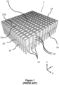
- stackable containers are stacked on top of one another to form stacks 12.
- the stacks 12 are arranged in a grid frame structure 14 in a warehousing or manufacturing environment.
- Figure 1 is a schematic perspective view of the frame structure 14, and
- Figure 2 is a top-down view showing a single stack 12 of bins 10 arranged within the frame structure 14.
- Each bin 10 typically holds a plurality of product items (not shown), and the product items within a bin 10 may be identical, or may be of different product types depending on the application.
- the frame structure 14 comprises a plurality of upright members 16 that support horizontal members 18, 20.
- a first set of parallel horizontal members 18 is arranged perpendicularly to a second set of parallel horizontal members 20 to form a plurality of horizontal grid structures supported by the upright members 16.
- the members 16, 18, 20 are typically manufactured from metal.
- the bins 10 are stacked between the members 16, 18, 20 of the frame structure 14, so that the frame structure 14 guards against horizontal movement of the stacks 12 of bins 10, and guides vertical movement of the bins 10.
- the top level of the frame structure 14 includes rails 22 arranged in a grid pattern across the top of the stacks 12.
- the rails 22 support a plurality of robotic load handling devices 30.
- a first set 22a of parallel rails 22 guide movement of the load handling devices 30 in a first direction (X) across the top of the frame structure 14, and a second set 22b of parallel rails 22, arranged perpendicular to the first set 22a, guide movement of the load handling devices 30 in a second direction (Y), perpendicular to the first direction.
- the rails 22 allow movement of the load handling devices 30 in two dimensions in the X-Y plane, so that a load handling device 30 can be moved into position above any of the stacks 12.
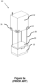
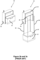
- Each load handling device 30 comprises a vehicle 32 which is arranged to travel in the X and Y directions on the rails 22 of the frame structure 14, above the stacks 12.
- a first set of wheels 34 consisting of a pair of wheels 34 on the front of the vehicle 32 and a pair of wheels 34 on the back of the vehicle 32, are arranged to engage with two adjacent rails of the first set 22a of rails 22.
- a second set of wheels 36 consisting of a pair of wheels 36 on each side of the vehicle 32, are arranged to engage with two adjacent rails of the second set 22b of rails 22.
- Each set of wheels 34, 36 can be lifted and lowered, so that either the first set of wheels 34 or the second set of wheels 36 is engaged with the respective set of rails 22a, 22b at any one time.
- the wheels 34 can be driven, by way of a drive mechanism (not shown) housed in the vehicle 32, to move the load handling device 30 in the X direction.
- a drive mechanism housed in the vehicle 32
- the first set of wheels 34 are lifted clear of the rails 22, and the second set of wheels 36 are lowered into engagement with the second set of rails 22a.
- the drive mechanism can then be used to drive the second set of wheels 36 to achieve movement in the Y direction.
- one or more robotic load handling devices 30 can move around the top surface of the stacks 12 on the frame structure 14 under the control of a central picking system (not shown).
- Each robotic load handling device 30 is provided with means for lifting out one or more bins or containers from the stack to access the required products. In this way, multiple products can be accessed from multiple locations in the grid and stacks at any one time.
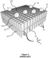
- Figure 4 shows a typical storage system as described above, the system having a plurality of load handling devices 30 active on the stacks 12.
- a robotic service device 50 is positioned on the grid 14.
- a first form of robotic service device 50 which lies outside the scope of the present invention but is useful for understanding the invention, will now be described with reference to Figures 5 , 7 and 11 .
- the robotic service device 50 comprises a vehicle 52 having first and second sets of wheels 54, 56 that are engageable with the first and second sets 22a, 22b of rails 22, respectively.
- the first and second sets of wheels 54, 56 of the robotic service device 50 can be moved vertically with respect to the vehicle 50 to engage or disengage the wheels from the corresponding set of rails 22a, 22b.
- the robotic service device 50 can be moved in the X and Y directions in the horizontal plane on the top of the frame structure 14.
- the device 50 occupies a single grid space formed by the tracks 22 on the top of the storage system framework. As described above in more detail, each grid space defines a location for a stack 12 of containers 10.
- the service device 50 may be moved under the control of the same utility controlling the load handling devices 30 on the storage system, in to any location above a stack 12 of containers 10 on the storage system.
- the device 50 is further provided with one or more spray device 70 capable of discharging a fire extinguishing material 60.
- the one or more spray device may be movable so that the spray device can be directed onto a fire so that the fire extinguishing material is discharged directly onto a fire.
- the device 50 is provided with a camera means 72 to assist with in locating the fire or any other heat source.
- the robotic service device 50 may be provided with suitable pumping means to pump the fire extinguishing material, from a tank or supply located within the device, out of the nozzle toward the fire.
- suitable pumping means to pump the fire extinguishing material, from a tank or supply located within the device, out of the nozzle toward the fire.
- the directionality of the deployment of the material may be governed by the geometry of the nozzle or spray device. Alternatively it may be computer controlled or remotely but manually controlled by a user located at a control point on the system (not shown).
- fire detectors located throughout the storage system continuously monitor the system for signs of fire.
- the fire detectors can be selected by way of example only from smoke detectors, heat sensors, optical sensors, and audio sensors.
- heat sensors or other detecting means may be carried on the service device 50 and may be used to identify the position of a fire and direct the spray device towards the fire.
- the spray device 70 on the service device 50 may be under the control of the central picking system (not shown) and hence activated by any of the detectors operable on the system and in communication with the central control utility of the storage system.
- the mechanism of deploying the fire extinguishing material 60 need not be limited to a spray device 70. Any form of nozzle 70 or movable output of the fire extinguishing material tank or supply may be used to direct the material in the direction of the fire.
- the service device may be provided with sealing means for sealing one or more containers or bins to prevent any fire spreading and vacuum means to remove air from the vicinity of the fire once the fire is contained in a given container or number of containers 10.
- the sealing means may comprise fire retardant lids capable of engagement with the open top of the uppermost container 10 in the stack 12.
- the sealing means may comprise any other suitable member suitable for containing the fire within a stacked container 10.
- the sealing may comprises means for sealing larger sections of the storage system when deployed, for example fire blankets or the like.
- the camera means 72 of the service device 50 may be used to view the situation from a control position (not shown).
- service device 50 may be provided with sensor means instead of or in addition to camera means 72 to accurately locate the fire.
- the service device 50 discharges fire extinguishing material 60 from one or more spray device or other mechanism.
- the one or more spray device 70 moves as the fire extinguishing material is discharged to ensure that fire extinguishing material is applied to all areas of the fire.
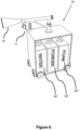
- Figure 6 shows an alternative form of device 50, capable of carrying multiple different types of fire extinguishing material 60' 60" 60′′′, which falls within the scope of the invention.
- material 60 may be used to extinguish the fire depending on the materials involved. These materials may include but not be limited to fire extinguishing foam, fire extinguishing powder and water or other fire extinguishing liquid. Suitable fire extinguishing materials may be selected from by way of example only powder, foam, fluid, aerosol, gas, pellets, gel, liquid and water. For simplicity these will all be referred to as fire extinguishing materials in the specification but it will be appreciated that this phrase is not limiting.
- the one or more spray device 70 can automatically oscillate as the fire extinguishing material 60 is discharged so that the fire extinguishing material 60 reaches all parts of a fire.
- the movement of spray device 70, as the fire extinguishing material 60 is discharged may be under the control of a computer utility or program forming a part of the control system of the central picking system (not shown).
- Figure 7 shows a further form of robotic service device 50 which is outside the scope of the invention but is useful for understanding the invention.
- the robotic service device occupies 2 x 2 grid spaces on the picking system.
- the remaining features of the device 50 are the same as those described in relation to Figures 5 and 6 .
- the increased size of the device enables a larger volume of fire extinguishing material to be carried on board the device 50.
- the additional fire extinguishing material carried on board the robotic service device may be sufficient to halt the spread of a small fire that may have started.
- the robotic service device need not occupy 2 x 2 grid spaces but may occupy 1 x 2 grid spaces, 2 x 3 grid spaces or any number of grid spaces.
- the size of the service device 50 may be selected depending on the size of the storage system, the nature of the materials stored within the system and/or the size of the containers and goods or materials within the system. For example in a chilled storage system in which fruit and vegetables are stored there may only be a requirement for a 1 x 1 service device 50 comprising fire extinguishing means. Whereas in a large ambient storage system in which the containers 10 are used to store matches or flammable materials such as alcohol, a larger service device 50 may be specified.
- the robotic service device 50 may be attached via a hose 74 and a hose reel 76 to a fire extinguishing material supply (not shown), such as a water supply or a foam supply or a supply of any other suitable fire extinguishing material.
- a fire extinguishing material supply such as a water supply or a foam supply or a supply of any other suitable fire extinguishing material.
- a small emergency supply of fire extinguishing material 60 may be carried on board the robotic service device 50 and supplemented by additional material 60 if required.
- the hose reel 76 is carried on the edge of the storage system by suitable structural members 80.
- the hose 74 may be transported to any required position on the storage system by a robotic service device 50, X movement being achieved by movement of the hose reel 76 on the structural member 80 and Y movement being achieved by movement of the robotic service device 50.
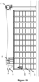
- Figure 10 shows the robotic fire extinguishing device 50 of Figures 8 and 9 as deployed on the storage system.
- the robotic service device of the type carrying three forms of fire extinguishing material 60 has been moved to a point above a detected fire 100 where deployment of the fire extinguishing material 60 via the spray nozzle 70 will halt or slow down the spread of the fire 100.
- Figure 11 shows a further form of robotic fire extinguishing service device 50 which is outside the scope of the invention but useful for understanding the invention.
- Figure 11 more particularly shows a form of device 50 where the fire extinguishing material 60 may be deposited at the site of a fire 100 without using a spray 70 or hose 74 mechanism.
- the robotic service device 50 comprises a tank 82 of suitable fire extinguishing material 60.
- the device further comprises means for emptying the contents of the tank 82.
- the means for emptying the tank 82 may comprise a remotely openable door or remotely pierceable diaphragm (not shown) in the base of the tank 82. Such remote actions may be controlled by a user or by the control utility of the storage system.
- the contents of the tank 82 is deposited on to the site of the fire 100.
- the sheer amount of fire extinguishing material deposited in a single action may act so as to extinguish a small fire with relative ease.
- Figures 12a and 12b show another device 50 outside the scope of the invention.
- a pod or pods 84 of fire extinguishing material 60 are stored in a load carrying portion of the device 50.
- the robotic service device 50 carrying the fire extinguishing pods 84 Upon detection of a fire 100 in the storage system, the robotic service device 50 carrying the fire extinguishing pods 84 is transported to the location of the fire 100 and the pods 84 deployed from the device 50. On deployment, the pod 84 casing is compromised, or the pod explodes, and the fire extinguishing material 60 contained therein is deployed above the fire. Such fire extinguishing pods 84 may only contain sufficient fire extinguishing material 60 to slow the progress of a fire. However, if the fire 100 is sufficiently smothered it may be possible to move the container 10 containing the fire from the stack 12 to a safe place remote from other goods or materials stored in the storage system. This may particularly be the case in a robotic system for storing and moving larger containers 10.
- pods 84 contain powder as a fire extinguishing or suppressing material 60 it is likely that the pods 84 may only activate with direct contact with the fire 100 or at high temperature. In this case, it may be necessary to deploy additional service devices to deploy additional fire extinguishing material.
- pods 84 comprise ball or grenade-style extinguishers. Such extinguishers may be manually operated by dropping, rolling or throwing into a fire. It will be appreciated that the ball or pod 84 will self-destruct once in contact with flame, dispersing a cloud of, for example, ABC dry chemical powder over the fire 100 which extinguishes the flame.
- pod-type extinguishers In known examples of pod-type extinguishers the coverage area is about 5 m2 (54 sq ft).
- One benefit of this type of fire extinguisher is that it may be used for passive suppression.
- the pod or ball can be placed in a fire prone area or held within the service device and will deploy if a fire develops, being triggered by heat.
- Most modern extinguishers of this type are designed to make a loud noise upon deployment.
- the pod-type fire extinguisher may be more easily stored within a load handling device until required, for long periods of time if necessary. Furthermore, in certain circumstances transporting large amounts of liquid within a robotic service device may be problematic over long distances, therefore use of pod-type materials may be advantageous.
- the service device 50 may comprise a substantially planar vehicle having first and second sets of wheels 54, 56 that are engageable with the first and second sets 22a, 22b of rails 22, of the grid 14 respectively.
- the planar vehicle 52 being provided with seating means 353 so as to be capable of carrying a user.
- the service device 50 may be robotically controlled by the picking system control but may also be manually driven by the user (not shown).
- the first and second sets of wheels 54, 56 of the service device 50 can be moved vertically with respect to the vehicle 52 to engage or disengage the wheels 54, 56 from the corresponding set of rails 22a, 22b.
- the service device 50 can be moved in the X and Y directions in the horizontal plane on the top of the grid 14.
- the service device 50 may be deployed on the grid 14 and driven to the fire site. Once in an appropriate position, any of the forms of the invention described above may be used.
- a single storage system may comprise more than one of the types of fire extinguishing robotic service devices 50.
- different types of fire for example, electrical, chemical etc
- different forms of fire extinguishing material 60 may need to be extinguished with different forms of fire extinguishing material 60. Therefore it may be advantageous for many types of robotic service devices to be in use on very large storage systems.
- dry powder extinguishing material may comprise sodium bicarbonate, potassium bicarbonate, monoammonium phosphate or any other suitable powder.
- foam fire extinguishing material may comprise aqueous film- forming foam, alcohol-resistant aqueous film-forming foams, film-forming fluoroprotein foams or any other suitable foam fire extinguishing material.
- water in the case where water is used as a fire extinguishing material, the water may be deployed as a spray, a mist or a stream and may be deployed under pressure.
- Other forms of fire extinguishing material may be used such as halons, halon-replacement clean agents, carbon dioxide or the like. It will be appreciated that depending on the material used, the deployment means will need to be selected accordingly. However, it will be apparent to a person skilled in the art what form of nozzle or spray mechanism is appropriate for which form of material 60.
- the robotic fire extinguishing devices 50 in accordance with the invention may provide sufficient fire extinguishing material to halt or slow the progress of a fire.
- the above described systems may prevent a sprinkler system deployment.
- Sprinkler systems can cause extensive damage and often deploy over a much larger area than required for the size of the fire.
- Such a sprinkler deployment can cause extensive damage to stored goods and to the system as a whole.
- such a sprinkler deployment may require significant amounts of stored goods to be disposed of at a large cost.
- one or more service device can be rapidly deployed to locate and if necessary extinguish the fire before it has a chance to spread without the need to await human fire fighters or to stop the whole system to allow fire fighters access. In systems of significant size or those which may be subject to large numbers of false alarms this can represent a substantial decrease in the down time of the system.
Landscapes
- Engineering & Computer Science (AREA)
- Mechanical Engineering (AREA)
- Health & Medical Sciences (AREA)
- Public Health (AREA)
- Business, Economics & Management (AREA)
- Emergency Management (AREA)
- Operations Research (AREA)
- Fire-Extinguishing By Fire Departments, And Fire-Extinguishing Equipment And Control Thereof (AREA)
- Manipulator (AREA)
- Warehouses Or Storage Devices (AREA)
Claims (12)
- Roboter-Kommissionier- und Lagersystem, umfassend: zwei im Wesentlichen rechtwinklige Sätze von Schienen (22), die ein Gitter bilden; gestapelte Container (10), die sich unter den Schienen (22) des Gitters befinden; Roboter-Lasthandhabungsvorrichtungen (30), die auf den Schienen (22), die das Gitter bilden, betrieben werden, dadurch gekennzeichnet, dass das Lagersystem ferner mindestens eine Servicevorrichtung (50) umfasst, wobei die Servicevorrichtung (50) umfasst: einen Körper (32), der ein Aufnahmemittel (82) zur Aufnahme von Feuerlöschmaterial (60, 60', 60", 84) definiert; zwei Sätze von Rädern (54, 56), auf denen der Körper (32) montiert ist, wobei der erste Satz von Rädern (54) so angeordnet ist, dass er mit mindestens zwei Schienen des ersten Satzes von Schienen (22) in Eingriff tritt, wobei der zweite Satz von Rädern (56) so angeordnet ist, dass er mit mindestens zwei Schienen des zweiten Satzes von Schienen (22) in Eingriff tritt, wobei einer des ersten oder zweiten Satzes von Rädern (54, 56) in Bezug auf den anderen des ersten oder zweiten Satzes von Rädern (54, 56) unabhängig beweglich und antreibbar ist, so dass nur ein Satz von Rädern zu jeder Zeit mit dem ersten und zweiten Satz von Schienen (22) in Eingriff tritt, wodurch eine Bewegung der Servicevorrichtung (50) entlang der Schienen (22) zu jedem Punkt auf dem Gitter ermöglicht wird, indem nur der Satz von Rädern (34, 36) angetrieben wird, der mit den Schienen (22) in Eingriff tritt; und ein Ausgabemittel (70) zum Ausgeben des Feuerlöschmaterials (60) aus dem Aufnahmemittel (82) der Servicevorrichtung (50) in Richtung eines Abschnitts des Kommissionier- und Lagersystems, so dass die Servicevorrichtung (50) angepasst ist, um ein Feuer innerhalb des Kommissionier- und Lagersystems zu löschen, wobei die Servicevorrichtung in der Lage ist, mehrere verschiedene Typen von Feuerlöschmaterial (60', 60", 60‴) gleichzeitig zu halten, die abhängig von den betreffenden Materialien zum Löschen des Feuers verwendet werden können.
- Roboter-Kommissionier- und Lagersystem nach Anspruch 1, wobei die Servicevorrichtung (50) ferner mit einem Feuerdetektionsmittel (72) versehen ist.
- Roboter-Kommissionier- und Lagersystem nach einem der Ansprüche 1 oder 2, wobei das Ausgabemittel eine Sprühvorrichtung (70) zum Ausgeben von Feuerlöschmaterial (60) umfasst, die an der Servicevorrichtung (50) angeordnet ist.
- Roboter-Kommissionier- und Lagersystem nach einem der vorhergehenden Ansprüche, ferner mit einem Schlauch (74) und einer Schlauchtrommel (76) zum Zuführen von Feuerlöschmaterial (60) zu der Servicevorrichtung (50).
- Roboter-Kommissionier- und Lagersystem nach Anspruch 4, wobei die Schlauchtrommel (76) von einem Bauelement (80) beweglich an einem Rand des Systems getragen ist.
- Roboter-Kommissionier- und Lagersystem nach einem der Ansprüche 3 bis 5, wobei die Feuerlöschmaterialien (60', 60", 60‴) aus Gel, Pulver, Schaum, Aerosol, Fluid, Gas, Pellets, Flüssigkeit und Wasser ausgewählt sind.
- Roboter-Kommissionier- und Lagersystem nach einem der Ansprüche 2 bis 6, wobei das Feuerdetektionsmittel (72) aus einem Rauchmelder, einem Wärmesensor, einem optischen Sensor und einem Audiosensor ausgewählt ist.
- Roboter-Kommissionier- und Lagersystem nach einem der vorhergehenden Ansprüche, wobei die Servicevorrichtung (50) ferner ein Kameramittel (72) umfasst, wodurch ein Sichtsystem bereitgestellt wird, so dass ein Benutzer ein Feuer aus der Ferne beobachten kann.
- Roboter-Kommissionier- und Lagersystem nach einem der vorhergehenden Ansprüche, wobei die Servicevorrichtung (50) ferner ein Sitzmittel umfasst, das für einen Benutzer geeignet ist, so dass die Servicevorrichtung (50) in Fällen verwendet werden kann, in denen ein manuelles Eingreifen in das Gitter erforderlich sein kann.
- Roboter-Kommissionier- und Lagersystem nach einem der vorhergehenden Ansprüche, wobei die Servicevorrichtung (50) ferner ein Anwendungsmittel zum Anwenden eines Dichtungsmittels zum Abdichten eines Teils des Lagersystems umfasst, um die Ausbreitung eines Feuers zu verhindern.
- Roboter-Kommissionier- und Lagersystem nach Anspruch 10, wobei die Dichtungsmittel feuerhemmende Deckel umfassen, die so angepasst sind, dass sie mit den Containern (10) in dem System in Eingriff treten.
- Roboter-Kommissionier- und Lagersystem nach einem der Ansprüche 10 oder 11, wobei das Dichtungsmittel eine Löschdecke umfasst.
Priority Applications (2)
| Application Number | Priority Date | Filing Date | Title |
|---|---|---|---|
| EP21201229.8A EP3960251A1 (de) | 2016-02-29 | 2017-02-28 | Robotische feuerlöschvorrichtung und handhabungsverfahren |
| PL17709612.0T PL3423164T5 (pl) | 2016-02-29 | 2017-02-28 | Robotyczne urządzenie gaśnicze oraz sposób obsługiwania |
Applications Claiming Priority (2)
| Application Number | Priority Date | Filing Date | Title |
|---|---|---|---|
| GBGB1603518.0A GB201603518D0 (en) | 2016-02-29 | 2016-02-29 | Robotic fire extinguishing device and handling method |
| PCT/EP2017/054670 WO2017148963A1 (en) | 2016-02-29 | 2017-02-28 | Robotic fire extinguishing device and handling method |
Related Child Applications (2)
| Application Number | Title | Priority Date | Filing Date |
|---|---|---|---|
| EP21201229.8A Division EP3960251A1 (de) | 2016-02-29 | 2017-02-28 | Robotische feuerlöschvorrichtung und handhabungsverfahren |
| EP21201229.8A Division-Into EP3960251A1 (de) | 2016-02-29 | 2017-02-28 | Robotische feuerlöschvorrichtung und handhabungsverfahren |
Publications (3)
| Publication Number | Publication Date |
|---|---|
| EP3423164A1 EP3423164A1 (de) | 2019-01-09 |
| EP3423164B1 EP3423164B1 (de) | 2022-02-09 |
| EP3423164B2 true EP3423164B2 (de) | 2025-04-30 |
Family
ID=55807097
Family Applications (2)
| Application Number | Title | Priority Date | Filing Date |
|---|---|---|---|
| EP17709612.0A Active EP3423164B2 (de) | 2016-02-29 | 2017-02-28 | Robotische feuerlöschvorrichtung und handhabungsverfahren |
| EP21201229.8A Pending EP3960251A1 (de) | 2016-02-29 | 2017-02-28 | Robotische feuerlöschvorrichtung und handhabungsverfahren |
Family Applications After (1)
| Application Number | Title | Priority Date | Filing Date |
|---|---|---|---|
| EP21201229.8A Pending EP3960251A1 (de) | 2016-02-29 | 2017-02-28 | Robotische feuerlöschvorrichtung und handhabungsverfahren |
Country Status (8)
| Country | Link |
|---|---|
| US (2) | US11701531B2 (de) |
| EP (2) | EP3423164B2 (de) |
| DK (1) | DK3423164T4 (de) |
| ES (1) | ES2910087T5 (de) |
| FI (1) | FI3423164T4 (de) |
| GB (2) | GB201603518D0 (de) |
| PL (1) | PL3423164T5 (de) |
| WO (1) | WO2017148963A1 (de) |
Families Citing this family (36)
| Publication number | Priority date | Publication date | Assignee | Title |
|---|---|---|---|---|
| CA3177838C (en) | 2017-03-20 | 2025-08-05 | Berkshire Grey Operating Company, Inc. | OBJECT PROCESSING SYSTEMS AND METHODS INCLUDING MOBILE MATRIX SUPPORT SYSTEMS |
| US10576621B2 (en) | 2017-03-23 | 2020-03-03 | Berkshire Grey, Inc. | Systems and methods for processing objects, including automated mobile matrix bins |
| WO2018175910A1 (en) | 2017-03-23 | 2018-09-27 | Berkshire Grey, Inc. | Systems and methods for processing objects, including automated mobile matrix carriers |
| WO2019084330A1 (en) | 2017-10-27 | 2019-05-02 | Berkshire Grey, Inc. | SYSTEMS AND METHODS FOR PROCESSING OBJECTS COMPRISING MOBILE MATRIX SUPPORT SYSTEMS |
| EP3737622B1 (de) | 2018-01-09 | 2025-10-15 | Autostore Technology AS | Verschiebungsmechanismus für ein ferngesteuertes fahrzeug |
| NO348639B1 (en) * | 2018-06-12 | 2025-04-14 | Autostore Tech As | A method of operating an automated storage and retrieval system |
| IT201800004432A1 (it) * | 2018-04-20 | 2019-10-20 | Ciarla Maria Cristina Lucia | Dispositivo a fune o catena di trasmissione per la traslazione bidirezionale ed il rifornimento idrico continuo di un cannone antincendio. |
| NO344995B1 (en) * | 2018-04-26 | 2020-08-17 | Autostore Tech As | Support vehicle for performing support operations in an automated storage and retrieval system |
| NO344889B1 (en) | 2018-06-06 | 2020-06-15 | Autostore Tech As | A service vehicle, an automated storage and retrieval system using such a service vehicle and a method thereof |
| WO2019233749A1 (en) | 2018-06-06 | 2019-12-12 | Autostore Technology AS | Service vehicle for extinguishing fire on and within an automated storage and retrieval system and a method thereof |
| ES2991321T3 (es) | 2018-06-12 | 2024-12-03 | Autostore Tech As | Un método de operación de un sistema automatizado de almacenamiento y recuperación |
| EP3807189B1 (de) | 2018-06-12 | 2025-01-08 | Autostore Technology As | Speichersystem |
| CN110870962A (zh) * | 2018-08-31 | 2020-03-10 | 成都市银隆新能源有限公司 | 一种锂电池化成灭火堆垛装置 |
| CN109350896A (zh) * | 2018-09-20 | 2019-02-19 | 温国雄 | 一种火力发电烟雾报警灭火装置 |
| CN109191755A (zh) * | 2018-10-09 | 2019-01-11 | 吉林工程技术师范学院 | 一种多功能火灾监测报警装置 |
| GB201902230D0 (en) | 2019-02-19 | 2019-04-03 | Ocado Innovation Ltd | Storage systems and methods |
| NO345321B1 (en) * | 2019-03-25 | 2020-12-07 | Autostore Tech As | Automated grid storage and retrieval system with foam-based fire prevention system |
| US12311207B2 (en) | 2019-03-25 | 2025-05-27 | Autostore Technology AS | Automated grid storage and retrieval system with foam-based fire prevention system |
| NO20190546A1 (en) | 2019-04-25 | 2020-10-26 | Autostore Tech As | An automated storage and retrieval system with fire detection device and methods of locating and/or verifying fire or smoke in an automated storage and retrieval system |
| CN110215625A (zh) * | 2019-05-12 | 2019-09-10 | 陕西理工大学 | 一种基于视频双感处理的建筑消防机器人 |
| US11058906B2 (en) * | 2019-06-06 | 2021-07-13 | Shenzhen Qianhai Ruifu Technology Co., Ltd. | Sweeping and fire extinguishing device |
| US11080990B2 (en) | 2019-08-05 | 2021-08-03 | Factory Mutual Insurance Company | Portable 360-degree video-based fire and smoke detector and wireless alerting system |
| CN110448841A (zh) * | 2019-08-27 | 2019-11-15 | 南京涵曦月自动化科技有限公司 | 一种智能灭火机器人的智能灭火控制系统 |
| NO347754B1 (en) * | 2019-09-02 | 2024-03-18 | Autostore Tech As | Method, and associated system, of providing an operator access to a target storage position in an automated storage and retrieval system |
| CN110917529B (zh) * | 2019-12-09 | 2021-08-20 | 国网智能科技股份有限公司 | 一种变电站消防机器人及其作业方法 |
| GB202017601D0 (en) * | 2020-11-06 | 2020-12-23 | Ocado Innovation Ltd | Storage system and storage container |
| TWI846982B (zh) * | 2020-11-18 | 2024-07-01 | 致茂電子股份有限公司 | 電子元件的滅火系統與方法 |
| WO2022120119A1 (en) * | 2020-12-04 | 2022-06-09 | Nimble Robotics, Inc. | Mobile robot and robotic farming system |
| CN113117277A (zh) * | 2021-04-08 | 2021-07-16 | 武汉理工大学 | 高性能安全性固态锂电池用于消防机器人 |
| CN113384840B (zh) * | 2021-07-04 | 2022-04-26 | 兴化市方圆消防器材有限公司 | 一种可补充型移动干粉灭火装置 |
| NO20211250A1 (en) * | 2021-10-18 | 2023-04-19 | Autostore Tech As | A service vehicle for an automated storage and retrieval system |
| GB2613866B (en) * | 2021-12-17 | 2024-10-02 | Ocado Innovation Ltd | An Adjustable spacer |
| NO347454B1 (en) * | 2022-04-28 | 2023-11-06 | Autostore Tech As | A system, method and computer program product for rental of physical items |
| DE102023101670A1 (de) * | 2023-01-24 | 2024-07-25 | Amova Gmbh | Feuerlöschkonzept in Hochregallager II |
| EP4588528A1 (de) * | 2024-01-22 | 2025-07-23 | Autostore Technology As | Feuerunterdrückungsmodul für stapelbaren behälter |
| EP4588529A1 (de) * | 2024-01-22 | 2025-07-23 | Autostore Technology As | Lagerbehälter |
Citations (1)
| Publication number | Priority date | Publication date | Assignee | Title |
|---|---|---|---|---|
| JPH09221201A (ja) † | 1996-02-20 | 1997-08-26 | Mitsubishi Heavy Ind Ltd | 消火機能付きスタッカクレーン |
Family Cites Families (28)
| Publication number | Priority date | Publication date | Assignee | Title |
|---|---|---|---|---|
| FR2385411A1 (fr) * | 1977-03-28 | 1978-10-27 | Schmittmann Gmbh Dr H | Vehicule de lutte contre l'incendie |
| DE4003777C1 (de) * | 1990-02-08 | 1991-03-14 | Hannover Sicherheitstechnik Gmbh, 3000 Hannover, De | |
| JP3128629B2 (ja) * | 1991-10-18 | 2001-01-29 | 能美防災株式会社 | 機械式駐車場の消火システム |
| ES2155847T3 (es) * | 1992-11-12 | 2001-06-01 | Fm Patentverwertung Kg | Dispositivo para almacenar objetos en un bloque de almacenaje. |
| JP3123424B2 (ja) | 1996-02-20 | 2001-01-09 | 鹿島建設株式会社 | 立体自動倉庫の自動消火方法および自動消火パレット |
| TW200603858A (en) | 2005-03-14 | 2006-02-01 | Richard Kao | Remote-controllable rail-guided removable fire fighter |
| US7909112B2 (en) * | 2007-05-03 | 2011-03-22 | Decker Gordon Michael | Compact mobile fire attack vehicle mountable to an emergency vehicle |
| JP5458856B2 (ja) | 2009-12-14 | 2014-04-02 | 村田機械株式会社 | 自動倉庫システム及び消火ユニット |
| US8381826B2 (en) * | 2010-03-29 | 2013-02-26 | Hadi A. Al-Azemi | Fire fighting robot |
| JP5590395B2 (ja) * | 2010-11-26 | 2014-09-17 | 株式会社ダイフク | 自動倉庫設備 |
| CN102275475A (zh) * | 2011-06-01 | 2011-12-14 | 公安部上海消防研究所 | 路轨两用消防车轨道行驶悬架系统 |
| TWM452046U (zh) * | 2011-11-11 | 2013-05-01 | Yi-Ping Lee | 自走式滅火機器人 |
| ES2422668B1 (es) | 2012-02-10 | 2014-07-01 | Big Blue Systems, S.L. | Dispositivo para la extincion de incendios |
| CN102921138A (zh) | 2012-10-11 | 2013-02-13 | 刘忠顺 | 探测器喷洒器移动式自动灭火系统 |
| NO334806B1 (no) | 2012-11-13 | 2014-06-02 | Jakob Hatteland Logistics As | Lagringssystem |
| NO335839B1 (no) * | 2012-12-10 | 2015-03-02 | Jakob Hatteland Logistics As | Robot for transport av lagringsbeholdere |
| CN103171851B (zh) | 2013-04-03 | 2015-05-27 | 上海速锐信息技术有限公司 | 一种具有爬坡功能的智能四向穿梭车 |
| GB201314313D0 (en) | 2013-08-09 | 2013-09-25 | Ocado Ltd | Apparatus for retrieving units from a storage system |
| GB201404870D0 (en) * | 2014-03-18 | 2014-04-30 | Ocado Ltd | Robotic service device and handling method |
| NO340313B1 (no) | 2014-01-08 | 2017-03-27 | Jakob Hatteland Logistics As | Fjernstyrt kjøretøy for å plukke opp lagringsbeholdere fra et lagringssystem, lagringssystem for lagring av beholdere og fremgangsmåte for å bytte en strømkilde |
| NO338156B1 (no) | 2014-02-19 | 2016-08-01 | Jakob Hatteland Logistics As | Avkjølt lagringssystem |
| CN203777559U (zh) | 2014-03-10 | 2014-08-20 | 赵钢 | 智慧安全防护整合系统载具 |
| DE202014003113U1 (de) * | 2014-04-10 | 2014-04-24 | Raumaster Paper Oy | Meldeanlage und Vertikalrollenlager |
| GB201409883D0 (en) * | 2014-06-03 | 2014-07-16 | Ocado Ltd | Methods, systems, and apparatus for controlling movement of transporting devices |
| GB2527543A (en) | 2014-06-25 | 2015-12-30 | Ocado Innovation Ltd | System and method for managing shipping containers |
| CN104298162A (zh) * | 2014-09-29 | 2015-01-21 | 北华大学 | 仓库火灾预警机器人控制系统 |
| CN205274386U (zh) | 2015-12-22 | 2016-06-01 | 湖州上电科电器科学研究有限公司 | 一种智能高效穿梭车 |
| CN106178348B (zh) | 2016-06-28 | 2018-12-25 | 陈淑腾 | 一种回转式智能消防特种作业机器人 |
-
2016
- 2016-02-29 GB GBGB1603518.0A patent/GB201603518D0/en not_active Ceased
-
2017
- 2017-02-28 GB GB1703257.4A patent/GB2548485A/en not_active Withdrawn
- 2017-02-28 ES ES17709612T patent/ES2910087T5/es active Active
- 2017-02-28 WO PCT/EP2017/054670 patent/WO2017148963A1/en not_active Ceased
- 2017-02-28 EP EP17709612.0A patent/EP3423164B2/de active Active
- 2017-02-28 PL PL17709612.0T patent/PL3423164T5/pl unknown
- 2017-02-28 DK DK17709612.0T patent/DK3423164T4/da active
- 2017-02-28 FI FIEP17709612.0T patent/FI3423164T4/fi active
- 2017-02-28 US US15/998,962 patent/US11701531B2/en active Active
- 2017-02-28 EP EP21201229.8A patent/EP3960251A1/de active Pending
-
2023
- 2023-06-01 US US18/327,376 patent/US20230321469A1/en not_active Abandoned
Patent Citations (1)
| Publication number | Priority date | Publication date | Assignee | Title |
|---|---|---|---|---|
| JPH09221201A (ja) † | 1996-02-20 | 1997-08-26 | Mitsubishi Heavy Ind Ltd | 消火機能付きスタッカクレーン |
Also Published As
| Publication number | Publication date |
|---|---|
| US11701531B2 (en) | 2023-07-18 |
| DK3423164T4 (da) | 2025-08-04 |
| ES2910087T5 (en) | 2025-08-28 |
| EP3960251A1 (de) | 2022-03-02 |
| PL3423164T3 (pl) | 2022-05-30 |
| WO2017148963A1 (en) | 2017-09-08 |
| GB201703257D0 (en) | 2017-04-12 |
| US20190240517A1 (en) | 2019-08-08 |
| FI3423164T4 (fi) | 2025-08-06 |
| EP3423164A1 (de) | 2019-01-09 |
| EP3423164B1 (de) | 2022-02-09 |
| GB201603518D0 (en) | 2016-04-13 |
| PL3423164T5 (pl) | 2025-08-18 |
| GB2548485A (en) | 2017-09-20 |
| US20230321469A1 (en) | 2023-10-12 |
| DK3423164T3 (da) | 2022-04-04 |
| ES2910087T3 (es) | 2022-05-11 |
Similar Documents
| Publication | Publication Date | Title |
|---|---|---|
| US20230321469A1 (en) | Robotic fire extinguishing device and handling method | |
| US20250108973A1 (en) | Storage systems and methods | |
| EP3283402B1 (de) | Speichersystem mit trennmitteln und verfahren | |
| EP2838817B1 (de) | Brandschutzsprinklersystem für regallager | |
| EP3215235B1 (de) | Brandschutzeinheit | |
| GB2541965A (en) | Storage systems and methods | |
| JP3123424B2 (ja) | 立体自動倉庫の自動消火方法および自動消火パレット | |
| US12030716B2 (en) | Storage system with partition means and methods | |
| US12338111B2 (en) | Stacker crane | |
| US20150165253A1 (en) | Laser material processing systems configured to suppress self-sustained combustion, and associated apparatuses and methods | |
| TW202430251A (zh) | 高架倉庫中的滅火方案 | |
| JP7738400B2 (ja) | 搬送ロボット稼働設備用防災システム | |
| TR2023016257A1 (tr) | Köprülü vi̇nç si̇stemleri̇ne uyumlanabi̇li̇r bi̇r yangin söndürme terti̇bati | |
| EP4588528A1 (de) | Feuerunterdrückungsmodul für stapelbaren behälter | |
| EP4588823A1 (de) | Längliches rahmenelement | |
| KR20250167405A (ko) | 물류로봇을 이용한 물류창고 화재확산방지 및 소화장치 |
Legal Events
| Date | Code | Title | Description |
|---|---|---|---|
| STAA | Information on the status of an ep patent application or granted ep patent |
Free format text: STATUS: UNKNOWN |
|
| STAA | Information on the status of an ep patent application or granted ep patent |
Free format text: STATUS: THE INTERNATIONAL PUBLICATION HAS BEEN MADE |
|
| PUAI | Public reference made under article 153(3) epc to a published international application that has entered the european phase |
Free format text: ORIGINAL CODE: 0009012 |
|
| STAA | Information on the status of an ep patent application or granted ep patent |
Free format text: STATUS: REQUEST FOR EXAMINATION WAS MADE |
|
| 17P | Request for examination filed |
Effective date: 20180914 |
|
| AK | Designated contracting states |
Kind code of ref document: A1 Designated state(s): AL AT BE BG CH CY CZ DE DK EE ES FI FR GB GR HR HU IE IS IT LI LT LU LV MC MK MT NL NO PL PT RO RS SE SI SK SM TR |
|
| AX | Request for extension of the european patent |
Extension state: BA ME |
|
| DAV | Request for validation of the european patent (deleted) | ||
| DAX | Request for extension of the european patent (deleted) | ||
| STAA | Information on the status of an ep patent application or granted ep patent |
Free format text: STATUS: EXAMINATION IS IN PROGRESS |
|
| 17Q | First examination report despatched |
Effective date: 20191218 |
|
| GRAP | Despatch of communication of intention to grant a patent |
Free format text: ORIGINAL CODE: EPIDOSNIGR1 |
|
| STAA | Information on the status of an ep patent application or granted ep patent |
Free format text: STATUS: GRANT OF PATENT IS INTENDED |
|
| RIC1 | Information provided on ipc code assigned before grant |
Ipc: A62C 35/13 20060101AFI20210519BHEP Ipc: A62C 37/40 20060101ALI20210519BHEP Ipc: B65G 1/04 20060101ALI20210519BHEP Ipc: A62C 3/00 20060101ALI20210519BHEP Ipc: A62C 27/00 20060101ALI20210519BHEP |
|
| INTG | Intention to grant announced |
Effective date: 20210621 |
|
| GRAS | Grant fee paid |
Free format text: ORIGINAL CODE: EPIDOSNIGR3 |
|
| GRAA | (expected) grant |
Free format text: ORIGINAL CODE: 0009210 |
|
| STAA | Information on the status of an ep patent application or granted ep patent |
Free format text: STATUS: THE PATENT HAS BEEN GRANTED |
|
| AK | Designated contracting states |
Kind code of ref document: B1 Designated state(s): AL AT BE BG CH CY CZ DE DK EE ES FI FR GB GR HR HU IE IS IT LI LT LU LV MC MK MT NL NO PL PT RO RS SE SI SK SM TR |
|
| REG | Reference to a national code |
Ref country code: GB Ref legal event code: FG4D |
|
| REG | Reference to a national code |
Ref country code: CH Ref legal event code: EP Ref country code: AT Ref legal event code: REF Ref document number: 1467141 Country of ref document: AT Kind code of ref document: T Effective date: 20220215 |
|
| REG | Reference to a national code |
Ref country code: IE Ref legal event code: FG4D |
|
| REG | Reference to a national code |
Ref country code: DE Ref legal event code: R096 Ref document number: 602017053137 Country of ref document: DE |
|
| REG | Reference to a national code |
Ref country code: DK Ref legal event code: T3 Effective date: 20220331 |
|
| REG | Reference to a national code |
Ref country code: NL Ref legal event code: FP |
|
| REG | Reference to a national code |
Ref country code: SE Ref legal event code: TRGR |
|
| REG | Reference to a national code |
Ref country code: FI Ref legal event code: FGE |
|
| REG | Reference to a national code |
Ref country code: ES Ref legal event code: FG2A Ref document number: 2910087 Country of ref document: ES Kind code of ref document: T3 Effective date: 20220511 |
|
| REG | Reference to a national code |
Ref country code: LT Ref legal event code: MG9D |
|
| REG | Reference to a national code |
Ref country code: NO Ref legal event code: T2 Effective date: 20220209 |
|
| PG25 | Lapsed in a contracting state [announced via postgrant information from national office to epo] |
Ref country code: RS Free format text: LAPSE BECAUSE OF FAILURE TO SUBMIT A TRANSLATION OF THE DESCRIPTION OR TO PAY THE FEE WITHIN THE PRESCRIBED TIME-LIMIT Effective date: 20220209 Ref country code: PT Free format text: LAPSE BECAUSE OF FAILURE TO SUBMIT A TRANSLATION OF THE DESCRIPTION OR TO PAY THE FEE WITHIN THE PRESCRIBED TIME-LIMIT Effective date: 20220609 Ref country code: LT Free format text: LAPSE BECAUSE OF FAILURE TO SUBMIT A TRANSLATION OF THE DESCRIPTION OR TO PAY THE FEE WITHIN THE PRESCRIBED TIME-LIMIT Effective date: 20220209 Ref country code: HR Free format text: LAPSE BECAUSE OF FAILURE TO SUBMIT A TRANSLATION OF THE DESCRIPTION OR TO PAY THE FEE WITHIN THE PRESCRIBED TIME-LIMIT Effective date: 20220209 Ref country code: BG Free format text: LAPSE BECAUSE OF FAILURE TO SUBMIT A TRANSLATION OF THE DESCRIPTION OR TO PAY THE FEE WITHIN THE PRESCRIBED TIME-LIMIT Effective date: 20220509 |
|
| REG | Reference to a national code |
Ref country code: HU Ref legal event code: AG4A Ref document number: E058362 Country of ref document: HU |
|
| PG25 | Lapsed in a contracting state [announced via postgrant information from national office to epo] |
Ref country code: LV Free format text: LAPSE BECAUSE OF FAILURE TO SUBMIT A TRANSLATION OF THE DESCRIPTION OR TO PAY THE FEE WITHIN THE PRESCRIBED TIME-LIMIT Effective date: 20220209 Ref country code: GR Free format text: LAPSE BECAUSE OF FAILURE TO SUBMIT A TRANSLATION OF THE DESCRIPTION OR TO PAY THE FEE WITHIN THE PRESCRIBED TIME-LIMIT Effective date: 20220510 |
|
| PG25 | Lapsed in a contracting state [announced via postgrant information from national office to epo] |
Ref country code: IS Free format text: LAPSE BECAUSE OF FAILURE TO SUBMIT A TRANSLATION OF THE DESCRIPTION OR TO PAY THE FEE WITHIN THE PRESCRIBED TIME-LIMIT Effective date: 20220609 |
|
| PG25 | Lapsed in a contracting state [announced via postgrant information from national office to epo] |
Ref country code: SM Free format text: LAPSE BECAUSE OF FAILURE TO SUBMIT A TRANSLATION OF THE DESCRIPTION OR TO PAY THE FEE WITHIN THE PRESCRIBED TIME-LIMIT Effective date: 20220209 Ref country code: SK Free format text: LAPSE BECAUSE OF FAILURE TO SUBMIT A TRANSLATION OF THE DESCRIPTION OR TO PAY THE FEE WITHIN THE PRESCRIBED TIME-LIMIT Effective date: 20220209 Ref country code: RO Free format text: LAPSE BECAUSE OF FAILURE TO SUBMIT A TRANSLATION OF THE DESCRIPTION OR TO PAY THE FEE WITHIN THE PRESCRIBED TIME-LIMIT Effective date: 20220209 Ref country code: EE Free format text: LAPSE BECAUSE OF FAILURE TO SUBMIT A TRANSLATION OF THE DESCRIPTION OR TO PAY THE FEE WITHIN THE PRESCRIBED TIME-LIMIT Effective date: 20220209 |
|
| REG | Reference to a national code |
Ref country code: DE Ref legal event code: R026 Ref document number: 602017053137 Country of ref document: DE |
|
| PLBI | Opposition filed |
Free format text: ORIGINAL CODE: 0009260 |
|
| PLAX | Notice of opposition and request to file observation + time limit sent |
Free format text: ORIGINAL CODE: EPIDOSNOBS2 |
|
| PG25 | Lapsed in a contracting state [announced via postgrant information from national office to epo] |
Ref country code: MC Free format text: LAPSE BECAUSE OF FAILURE TO SUBMIT A TRANSLATION OF THE DESCRIPTION OR TO PAY THE FEE WITHIN THE PRESCRIBED TIME-LIMIT Effective date: 20220209 Ref country code: AL Free format text: LAPSE BECAUSE OF FAILURE TO SUBMIT A TRANSLATION OF THE DESCRIPTION OR TO PAY THE FEE WITHIN THE PRESCRIBED TIME-LIMIT Effective date: 20220209 |
|
| 26 | Opposition filed |
Opponent name: AUTOSTORE TECHNOLOGY AS Effective date: 20221109 |
|
| REG | Reference to a national code |
Ref country code: AT Ref legal event code: UEP Ref document number: 1467141 Country of ref document: AT Kind code of ref document: T Effective date: 20220209 |
|
| PG25 | Lapsed in a contracting state [announced via postgrant information from national office to epo] |
Ref country code: SI Free format text: LAPSE BECAUSE OF FAILURE TO SUBMIT A TRANSLATION OF THE DESCRIPTION OR TO PAY THE FEE WITHIN THE PRESCRIBED TIME-LIMIT Effective date: 20220209 |
|
| PLBB | Reply of patent proprietor to notice(s) of opposition received |
Free format text: ORIGINAL CODE: EPIDOSNOBS3 |
|
| P01 | Opt-out of the competence of the unified patent court (upc) registered |
Effective date: 20230517 |
|
| PLBP | Opposition withdrawn |
Free format text: ORIGINAL CODE: 0009264 |
|
| REG | Reference to a national code |
Ref country code: FI Ref legal event code: FGE |
|
| PLAY | Examination report in opposition despatched + time limit |
Free format text: ORIGINAL CODE: EPIDOSNORE2 |
|
| PG25 | Lapsed in a contracting state [announced via postgrant information from national office to epo] |
Ref country code: MK Free format text: LAPSE BECAUSE OF FAILURE TO SUBMIT A TRANSLATION OF THE DESCRIPTION OR TO PAY THE FEE WITHIN THE PRESCRIBED TIME-LIMIT Effective date: 20220209 Ref country code: CY Free format text: LAPSE BECAUSE OF FAILURE TO SUBMIT A TRANSLATION OF THE DESCRIPTION OR TO PAY THE FEE WITHIN THE PRESCRIBED TIME-LIMIT Effective date: 20220209 |
|
| RAP4 | Party data changed (patent owner data changed or rights of a patent transferred) |
Owner name: OCADO INNOVATION LIMITED |
|
| PG25 | Lapsed in a contracting state [announced via postgrant information from national office to epo] |
Ref country code: TR Free format text: LAPSE BECAUSE OF FAILURE TO SUBMIT A TRANSLATION OF THE DESCRIPTION OR TO PAY THE FEE WITHIN THE PRESCRIBED TIME-LIMIT Effective date: 20220209 |
|
| PLBC | Reply to examination report in opposition received |
Free format text: ORIGINAL CODE: EPIDOSNORE3 |
|
| PG25 | Lapsed in a contracting state [announced via postgrant information from national office to epo] |
Ref country code: MT Free format text: LAPSE BECAUSE OF FAILURE TO SUBMIT A TRANSLATION OF THE DESCRIPTION OR TO PAY THE FEE WITHIN THE PRESCRIBED TIME-LIMIT Effective date: 20220209 |
|
| PGFP | Annual fee paid to national office [announced via postgrant information from national office to epo] |
Ref country code: NL Payment date: 20250218 Year of fee payment: 9 Ref country code: LU Payment date: 20250218 Year of fee payment: 9 |
|
| PGFP | Annual fee paid to national office [announced via postgrant information from national office to epo] |
Ref country code: HU Payment date: 20250220 Year of fee payment: 9 |
|
| PUAH | Patent maintained in amended form |
Free format text: ORIGINAL CODE: 0009272 |
|
| STAA | Information on the status of an ep patent application or granted ep patent |
Free format text: STATUS: PATENT MAINTAINED AS AMENDED |
|
| PGFP | Annual fee paid to national office [announced via postgrant information from national office to epo] |
Ref country code: DE Payment date: 20250218 Year of fee payment: 9 |
|
| PGFP | Annual fee paid to national office [announced via postgrant information from national office to epo] |
Ref country code: DK Payment date: 20250224 Year of fee payment: 9 Ref country code: FI Payment date: 20250220 Year of fee payment: 9 |
|
| PGFP | Annual fee paid to national office [announced via postgrant information from national office to epo] |
Ref country code: IE Payment date: 20250220 Year of fee payment: 9 Ref country code: SE Payment date: 20250218 Year of fee payment: 9 |
|
| PGFP | Annual fee paid to national office [announced via postgrant information from national office to epo] |
Ref country code: NO Payment date: 20250221 Year of fee payment: 9 |
|
| PGFP | Annual fee paid to national office [announced via postgrant information from national office to epo] |
Ref country code: AT Payment date: 20250219 Year of fee payment: 9 Ref country code: CH Payment date: 20250301 Year of fee payment: 9 Ref country code: BE Payment date: 20250218 Year of fee payment: 9 |
|
| PGFP | Annual fee paid to national office [announced via postgrant information from national office to epo] |
Ref country code: PL Payment date: 20250221 Year of fee payment: 9 Ref country code: FR Payment date: 20250221 Year of fee payment: 9 Ref country code: CZ Payment date: 20250220 Year of fee payment: 9 |
|
| PGFP | Annual fee paid to national office [announced via postgrant information from national office to epo] |
Ref country code: GB Payment date: 20250220 Year of fee payment: 9 Ref country code: IT Payment date: 20250221 Year of fee payment: 9 |
|
| 27A | Patent maintained in amended form |
Effective date: 20250430 |
|
| AK | Designated contracting states |
Kind code of ref document: B2 Designated state(s): AL AT BE BG CH CY CZ DE DK EE ES FI FR GB GR HR HU IE IS IT LI LT LU LV MC MK MT NL NO PL PT RO RS SE SI SK SM TR |
|
| REG | Reference to a national code |
Ref country code: DE Ref legal event code: R102 Ref document number: 602017053137 Country of ref document: DE |
|
| PGFP | Annual fee paid to national office [announced via postgrant information from national office to epo] |
Ref country code: ES Payment date: 20250331 Year of fee payment: 9 |
|
| REG | Reference to a national code |
Ref country code: SE Ref legal event code: RPEO |
|
| REG | Reference to a national code |
Ref country code: DK Ref legal event code: T4 Effective date: 20250728 |
|
| REG | Reference to a national code |
Ref country code: NL Ref legal event code: FP |
|
| REG | Reference to a national code |
Ref country code: ES Ref legal event code: DC2A Ref document number: 2910087 Country of ref document: ES Kind code of ref document: T5 Effective date: 20250828 |