EP3422073B1 - Phase-contrast microscope and imaging method - Google Patents
Phase-contrast microscope and imaging method Download PDFInfo
- Publication number
- EP3422073B1 EP3422073B1 EP17756280.8A EP17756280A EP3422073B1 EP 3422073 B1 EP3422073 B1 EP 3422073B1 EP 17756280 A EP17756280 A EP 17756280A EP 3422073 B1 EP3422073 B1 EP 3422073B1
- Authority
- EP
- European Patent Office
- Prior art keywords
- liquid surface
- surface shape
- phase difference
- difference image
- liquid
- Prior art date
- Legal status (The legal status is an assumption and is not a legal conclusion. Google has not performed a legal analysis and makes no representation as to the accuracy of the status listed.)
- Active
Links
- 238000003384 imaging method Methods 0.000 title claims description 80
- 239000007788 liquid Substances 0.000 claims description 173
- 230000003287 optical effect Effects 0.000 claims description 173
- 238000009826 distribution Methods 0.000 claims description 71
- 230000005499 meniscus Effects 0.000 claims description 64
- 238000005286 illumination Methods 0.000 claims description 56
- 238000013041 optical simulation Methods 0.000 claims description 21
- 238000005259 measurement Methods 0.000 claims description 14
- 238000009499 grossing Methods 0.000 claims description 8
- 238000005314 correlation function Methods 0.000 claims description 4
- 238000010586 diagram Methods 0.000 description 21
- 238000000034 method Methods 0.000 description 11
- 210000004027 cell Anatomy 0.000 description 7
- 239000004973 liquid crystal related substance Substances 0.000 description 6
- NCGICGYLBXGBGN-UHFFFAOYSA-N 3-morpholin-4-yl-1-oxa-3-azonia-2-azanidacyclopent-3-en-5-imine;hydrochloride Chemical compound Cl.[N-]1OC(=N)C=[N+]1N1CCOCC1 NCGICGYLBXGBGN-UHFFFAOYSA-N 0.000 description 3
- LFQSCWFLJHTTHZ-UHFFFAOYSA-N Ethanol Chemical compound CCO LFQSCWFLJHTTHZ-UHFFFAOYSA-N 0.000 description 3
- OKKJLVBELUTLKV-UHFFFAOYSA-N Methanol Chemical compound OC OKKJLVBELUTLKV-UHFFFAOYSA-N 0.000 description 3
- XLYOFNOQVPJJNP-UHFFFAOYSA-N water Substances O XLYOFNOQVPJJNP-UHFFFAOYSA-N 0.000 description 3
- WSFSSNUMVMOOMR-UHFFFAOYSA-N Formaldehyde Chemical compound O=C WSFSSNUMVMOOMR-UHFFFAOYSA-N 0.000 description 2
- 230000002238 attenuated effect Effects 0.000 description 2
- 230000000694 effects Effects 0.000 description 2
- 238000004364 calculation method Methods 0.000 description 1
- 230000000295 complement effect Effects 0.000 description 1
- 210000004748 cultured cell Anatomy 0.000 description 1
- 230000008020 evaporation Effects 0.000 description 1
- 238000001704 evaporation Methods 0.000 description 1
- 239000000463 material Substances 0.000 description 1
- 229910044991 metal oxide Inorganic materials 0.000 description 1
- 150000004706 metal oxides Chemical class 0.000 description 1
- 239000004065 semiconductor Substances 0.000 description 1
- 210000000130 stem cell Anatomy 0.000 description 1
- 238000002834 transmittance Methods 0.000 description 1
Images


Classifications
-
- G—PHYSICS
- G02—OPTICS
- G02B—OPTICAL ELEMENTS, SYSTEMS OR APPARATUS
- G02B21/00—Microscopes
- G02B21/06—Means for illuminating specimens
-
- G—PHYSICS
- G02—OPTICS
- G02B—OPTICAL ELEMENTS, SYSTEMS OR APPARATUS
- G02B21/00—Microscopes
- G02B21/06—Means for illuminating specimens
- G02B21/08—Condensers
- G02B21/14—Condensers affording illumination for phase-contrast observation
-
- G—PHYSICS
- G02—OPTICS
- G02B—OPTICAL ELEMENTS, SYSTEMS OR APPARATUS
- G02B21/00—Microscopes
- G02B21/06—Means for illuminating specimens
- G02B21/08—Condensers
- G02B21/086—Condensers for transillumination only
-
- G—PHYSICS
- G02—OPTICS
- G02B—OPTICAL ELEMENTS, SYSTEMS OR APPARATUS
- G02B21/00—Microscopes
- G02B21/36—Microscopes arranged for photographic purposes or projection purposes or digital imaging or video purposes including associated control and data processing arrangements
-
- G—PHYSICS
- G02—OPTICS
- G02B—OPTICAL ELEMENTS, SYSTEMS OR APPARATUS
- G02B21/00—Microscopes
- G02B21/36—Microscopes arranged for photographic purposes or projection purposes or digital imaging or video purposes including associated control and data processing arrangements
- G02B21/365—Control or image processing arrangements for digital or video microscopes
-
- G—PHYSICS
- G02—OPTICS
- G02B—OPTICAL ELEMENTS, SYSTEMS OR APPARATUS
- G02B26/00—Optical devices or arrangements for the control of light using movable or deformable optical elements
- G02B26/06—Optical devices or arrangements for the control of light using movable or deformable optical elements for controlling the phase of light
-
- G—PHYSICS
- G02—OPTICS
- G02B—OPTICAL ELEMENTS, SYSTEMS OR APPARATUS
- G02B26/00—Optical devices or arrangements for the control of light using movable or deformable optical elements
- G02B26/08—Optical devices or arrangements for the control of light using movable or deformable optical elements for controlling the direction of light
- G02B26/0875—Optical devices or arrangements for the control of light using movable or deformable optical elements for controlling the direction of light by means of one or more refracting elements
-
- G—PHYSICS
- G02—OPTICS
- G02B—OPTICAL ELEMENTS, SYSTEMS OR APPARATUS
- G02B27/00—Optical systems or apparatus not provided for by any of the groups G02B1/00 - G02B26/00, G02B30/00
- G02B27/0025—Optical systems or apparatus not provided for by any of the groups G02B1/00 - G02B26/00, G02B30/00 for optical correction, e.g. distorsion, aberration
- G02B27/0068—Optical systems or apparatus not provided for by any of the groups G02B1/00 - G02B26/00, G02B30/00 for optical correction, e.g. distorsion, aberration having means for controlling the degree of correction, e.g. using phase modulators, movable elements
-
- G—PHYSICS
- G02—OPTICS
- G02B—OPTICAL ELEMENTS, SYSTEMS OR APPARATUS
- G02B3/00—Simple or compound lenses
- G02B3/12—Fluid-filled or evacuated lenses
- G02B3/14—Fluid-filled or evacuated lenses of variable focal length
-
- G—PHYSICS
- G06—COMPUTING; CALCULATING OR COUNTING
- G06T—IMAGE DATA PROCESSING OR GENERATION, IN GENERAL
- G06T7/00—Image analysis
- G06T7/50—Depth or shape recovery
- G06T7/55—Depth or shape recovery from multiple images
-
- H—ELECTRICITY
- H04—ELECTRIC COMMUNICATION TECHNIQUE
- H04N—PICTORIAL COMMUNICATION, e.g. TELEVISION
- H04N23/00—Cameras or camera modules comprising electronic image sensors; Control thereof
- H04N23/70—Circuitry for compensating brightness variation in the scene
- H04N23/71—Circuitry for evaluating the brightness variation
-
- G—PHYSICS
- G06—COMPUTING; CALCULATING OR COUNTING
- G06T—IMAGE DATA PROCESSING OR GENERATION, IN GENERAL
- G06T2207/00—Indexing scheme for image analysis or image enhancement
- G06T2207/10—Image acquisition modality
- G06T2207/10056—Microscopic image
-
- G06T5/70—
Definitions
- the present invention relates to a phase contrast microscope according to the preamble of claim 1 and an imaging method thereof.
- phase difference measurement has started to be widely used as a method for observing transparent cultured cells, such as stem cells, achromatically.
- a phase contrast microscope is used as one that performs such phase difference measurement.
- ring-shaped illumination light is emitted to an observation target, and direct light and diffracted light having passed through the observation target are incident on a phase plate. Then, the direct light is attenuated by a ring portion of the phase plate, and the diffracted light passes through a transparent portion of the phase plate.
- the direct light is attenuated by a ring portion of the phase plate, and the diffracted light passes through a transparent portion of the phase plate.
- the liquid surface shape formed by the meniscus In order to compensate for the optical path deviation due to the meniscus, information of the liquid surface shape formed by the meniscus is required. In a case where the liquid surface shape is known, it is possible to compensate for the optical path deviation. However, since the liquid surface formed by the meniscus is formed from the relationship between the material of the surface of a container, such as a well plate, and a liquid contained in the container, it is difficult to compensate for the optical path deviation considering all possible combinations that can be realistically present. Even within the same well, the liquid surface shape locally differs depending on the type and amount of liquid contained in the well and the state of the surface within the well. Therefore, it is not sufficient to measure the liquid surface shape once, but it is necessary to measure the liquid surface shape every observation. In addition, in the case of performing time-lapse imaging, the water level in the container changes due to evaporation of the solution, and the liquid surface shape also changes accordingly.
- JP2015-152650A discloses emitting measurement light to a plurality of positions on the liquid surface of the culture solution, detecting the amount of deviation of the measurement light, and calculating the shape of the liquid surface of the culture solution based on the amount of deviation.
- JP 2015 152 649 A discloses a phase contrast microscope according to the preamble of claim 1.
- US 2012/0257040 discloses an optical microscope also in accordance with the preamble of claim 1.
- a phase contrast microscope of the present invention comprises the features of claim 1.
- the liquid surface shape estimation unit estimates the liquid surface shape of the liquid in the container based on brightness distributions of a plurality of phase difference images acquired by performing a geometric optical simulation using a plurality of liquid surface shapes that have different curvatures and are set in advance.
- the liquid surface shape estimation unit calculates the correlation using a correlation function.
- the liquid surface shape estimation unit calculates the correlation based on a brightness value of an inflection point in the brightness distribution of the phase difference image acquired by using the geometric optical simulation and a brightness value of an inflection point in the brightness distribution of the phase difference image captured by the imaging unit.
- the liquid surface shape estimation unit sets at least one straight line, which extends from a central portion of a meniscus formed in the container toward an outer periphery of the container, on the phase difference image captured by the imaging unit and estimates the liquid surface shape of the liquid in the container based on a brightness distribution of the phase difference image on the set straight line.
- the liquid surface shape estimation unit sets the straight lines extending in a plurality of different directions and estimates the liquid surface shape of the liquid in the container based on brightness distributions of phase difference images on the plurality of straight lines.
- the liquid surface shape estimation unit performs smoothing processing on the phase difference image captured by the imaging unit, and estimates the liquid surface shape of the liquid in the container based on a brightness distribution of a phase difference image subjected to the smoothing processing.
- An imaging method of the present invention comprises the features of claim 8.
- the liquid surface shape of the liquid in the container is estimated based on the brightness distribution of the phase difference image captured by the imaging unit that captures a phase difference image for observation. Therefore, it is possible to estimate the liquid surface shape of the liquid in the container without providing a new measurement system for estimating the liquid surface shape.
- Fig. 1 is a diagram showing the schematic configuration of the microscope system of the present embodiment.
- the microscope system of the present embodiment includes an illumination light emission unit 10, an adjustment optical system 20, an imaging optical system 30, an imaging unit 40, a microscope control device 50, a display device 70, and an input device 80.
- a stage 61 is provided between the adjustment optical system 20 and the imaging optical system 30, and a culture container 60 in which a culture solution C as a liquid and an observation target S are contained is provided on the stage 61.
- the microscope system of the present embodiment includes a stage driving unit 62 for moving the stage 61 in X, Y, and Z directions.
- the X and Y directions are directions perpendicular to each other on a plane parallel to an observation target placement surface P, and the Z direction is a direction perpendicular to the X and Y directions.
- a phase contrast microscope body is formed by the illumination light emission unit 10, the adjustment optical system 20, the imaging optical system 30, the imaging unit 40, the stage 61, and the stage driving unit 62 that have been described above and an imaging optical system driving unit 34, and the microscope control device 50 controls the phase contrast microscope body.
- the specific configuration of the phase contrast microscope body will be described.
- the illumination light emission unit 10 emits illumination light for so-called phase difference measurement to the observation target S contained in the culture container 60.
- the illumination light emission unit 10 emits ring-shaped illumination light as the illumination light for phase difference measurement.
- the illumination light emission unit 10 of the present embodiment includes: a white light source 11 that emits white light; a slit plate 12 which has a ring-shaped slit, on which the white light emitted from the white light source 11 is incident, and which emits ring-shaped illumination light; and a condenser lens 13 on which the ring-shaped illumination light emitted from the slit plate 12 is incident and which emits the incident ring-shaped illumination light to the observation target S.
- the slit plate 12 is obtained by providing a ring-shaped slit, through which white light is transmitted, on a light screen for shielding the white light emitted from the white light source 11.
- the white light passes through the slit to form ring-shaped illumination light.
- the ring-shaped illumination light is formed using the slit plate 12 as described above, but the method of forming the ring-shaped illumination light is not limited thereto.
- the ring-shaped illumination light may be formed using a spatial light modulation element or the like.
- the ring-shaped illumination light is used as illumination light for phase difference measurement, but illumination light having a shape other than the ring shape may be used.
- Other shapes such as a triangular shape or a quadrangular shape, may be used as long as the illumination light has a conjugate shape with a phase plate to be described later.
- the culture container 60 placed on the stage 61 has its bottom surface as the observation target placement surface P, and a cell group or the like as the observation target S is disposed on the observation target placement surface P.
- the culture solution C is filled in the culture container 60, and a concave meniscus is formed on the liquid surface of the culture solution C.
- Examples of the culture container 60 include a laboratory dish and a well plate in which a plurality of wells are arranged. In the case of a well plate, the observation target S and the culture solution C are contained in each well, and a meniscus is formed for each well.
- a cell group cultured in the culture solution is set as the observation target S.
- the observation target S is not limited to cells in the culture solution, and cells fixed in a liquid, such as water, formalin, ethanol, and methanol, may be set as the observation target S. Also in this case, a meniscus is formed on the liquid surfaces of these liquids in the container.
- the adjustment optical system 20 adjusts the refraction of illumination light for phase difference measurement due to the liquid surface shape of the meniscus described above.
- the adjustment optical system 20 of the present embodiment includes an adjustment optical element 21 and an adjustment optical system driving unit 22.
- the adjustment optical element 21 is an optical element having a focal power. Specifically, a plano-convex lens having a curvature on the incidence surface or the exit surface, a biconvex lens having a curvature on both the incidence surface and the exit surface, a liquid crystal lens whose focal power is changed by voltage application, a liquid lens whose radius of curvature can be changed, a spatial light modulator capable of changing the focal length, and the like can be used.
- the adjustment optical system driving unit 22 adjusts the focal length by changing the focal power of the adjustment optical element 21 based on a control signal output from an adjustment optical system control unit 51 to be described later.
- the adjustment optical system driving unit 22 includes a mechanism for changing the position and the optical axis direction of the adjustment optical element 21.
- the adjustment optical system driving unit 22 applies a voltage corresponding to a desired focal length to the liquid crystal lens or the spatial light modulator.
- the adjustment optical system driving unit 22 adjusts the amount of liquid in the liquid lens according to a desired focal length, thereby adjusting the radius of curvature of the liquid lens.
- Fig. 2A is a diagram schematically showing a change in the position of the adjustment optical element 21 in the X, Y, and Z directions.
- Fig. 2B is a diagram schematically showing a change in the direction of the optical axis of the adjustment optical element 21.
- Fig. 2B is a diagram schematically showing the rotation adjustment of the optical axis of the adjustment optical element 21 around the X axis ( ⁇ ), the rotation adjustment of the optical axis of the adjustment optical element 21 around the Y axis ( ⁇ ), and the rotation adjustment of the optical axis of the adjustment optical element 21 around the Z axis ( ⁇ ).
- Fig. 2C schematically shows the adjustment of the focal power of the adjustment optical element 21.
- the method of adjusting the focal power is not limited thereto.
- the focal power can be adjusted by adjusting the applied voltage.
- the adjustment optical element 21 is moved in the X, Y, and Z directions.
- the adjustment optical element 21 does not necessarily need to be moved.
- the same effect as the deviation of the optical axis by the movement of the adjustment optical element 21 may be obtained by adjusting the applied voltage.
- the same effect as the rotation of the optical axis by the rotation of the adjustment optical element 21 itself may be obtained by adjusting the applied voltage.
- the adjustment optical element 21 is moved in the X and Y directions.
- the present invention is not limited thereto, and the relative positional relationship between the adjustment optical element 21 and the meniscus, which is formed in the culture container 60, in the X and Y directions may be changed by moving the stage 61 in the X and Y directions.
- one adjustment optical element 21 is used.
- the focal power may be adjusted by performing switching between a plurality of adjustment optical elements 21 having different focal lengths.
- the adjustment optical elements 21 may be exchanged automatically or manually.
- information of the type of the appropriate adjustment optical element 21 may be displayed on the display device 70, for example, based on the liquid surface shape estimated by a liquid surface shape estimation unit 54 to be described later, so that the user may manually exchange the adjustment optical elements 21 based on the display.
- the imaging optical system 30 includes an objective lens 31, a phase plate 32, an imaging lens 33, and the imaging optical system driving unit 34.
- the phase plate 32 is configured by forming a phase ring on a transparent plate that is transparent for the wavelength of the ring-shaped illumination light.
- the size of the slit of the slit plate 12 described above and the phase ring are in the conjugate relationship.
- the phase ring is obtained by forming a phase film, which shifts the phase of incidence lay by 1/4 wavelength, and a dimming filter, which is for attenuating the incidence lay, in a ring shape.
- Direct light incident on the phase plate 32 is transmitted through the phase ring.
- the phase of the direct light is shifted by 1/4 wavelength, and the brightness is weakened.
- most of the diffracted light diffracted by the observation target S passes through the transparent plate of the phase plate 32, and the phase and the brightness are not changed.
- the objective lens 31 is moved in the Z direction by the imaging optical system driving unit 34.
- autofocus control is performed by moving the objective lens 31 in the Z direction using the imaging optical system driving unit 34, so that the contrast of the image captured by the imaging unit 40 is adjusted.
- Direct light and diffracted light having passed through the phase plate 32 are incident on the imaging lens 33, and these light beams are imaged on the imaging unit 40.
- the imaging optical system driving unit 34 includes a mechanism for moving the objective lens 31 in the Z direction as described above.
- the imaging unit 40 includes an imaging element for capturing a phase difference image of the observation target S formed by the imaging lens 33.
- an imaging element a charge-coupled device (CCD) image sensor, a complementary metal-oxide semiconductor (CMOS) image sensor, and the like can be used.
- CCD charge-coupled device
- CMOS complementary metal-oxide semiconductor
- ring-shaped illumination light emitted from the illumination light emission unit 10 is emitted to the observation target S.
- the illumination light emitted to the observation target S is divided into direct light having passed straight through the observation target S and diffracted light diffracted by the observation target S.
- the direct light and the diffracted light transmitted through the observation target S are transmitted through the objective lens 31 and incident on the phase plate 32.
- the direct light transmitted through the observation target S is incident on the phase ring of the phase plate 32.
- the phase of the direct light is shifted by 1/4 wavelength, and the brightness is weakened.
- most of the diffracted light transmitted through the observation target S passes through a transparent portion of the phase plate 32.
- the direct light and the diffracted light transmitted through the phase plate 32 are imaged on the imaging surface of the imaging element by the imaging lens 33, and a phase difference image in which the contrast of an edge portion or the like is emphasized is captured by interference between the direct light and the diffracted light.
- the inside of the culture container 60 is scanned with illumination light by moving the stage 61 in the X and Y directions, and a phase difference image is captured for each region irradiated with the illumination light in the culture container 60.
- the microscope control device 50 shown in Fig. 1 is a computer including a central processing unit (CPU), a memory, a hard disk, and the like.
- CPU central processing unit
- memory a hard disk, and the like.
- the microscope control device 50 includes the adjustment optical system control unit 51 that controls the adjustment optical system driving unit 22, an imaging optical system control unit 52 that controls the imaging optical system driving unit 34, a stage control unit 53 that controls the stage driving unit 62, the liquid surface shape estimation unit 54 that estimates the liquid surface shape of the culture solution C in the culture container 60 based on the brightness distribution of the phase difference image captured by the imaging unit 40, and an adjustment information acquisition unit 55 that acquires adjustment information for adjusting the optical characteristics of the adjustment optical system 20 based on the liquid surface shape estimated by the liquid surface shape estimation unit 54.
- the liquid surface shape estimation unit 54 estimates the liquid surface shape of the culture solution C in the culture container 60 based on the brightness distribution of the phase difference image captured by the imaging unit 40 as described above. First, the principle of estimating the liquid surface shape of the culture solution C based on the brightness distribution of the phase difference image in this manner will be described.
- (I) of Fig. 3 shows an example of a phase difference image
- (II) of Fig. 3 is an enlarged view of a part (range surrounded by a square) of the phase difference image shown in (I) of Fig. 3
- a bright and dark pattern (brightness distribution) is formed concentrically. The reason why such a bright and dark pattern is formed will be described below.
- the illumination light transmitted through the central portion of the meniscus formed on the liquid surface of the culture solution C in the culture container 60 is hardly influenced by refraction due to the meniscus. Accordingly, the direct light is incident on the phase ring of the phase plate 32 to be attenuated. As a result, the phase difference image of the central portion of the meniscus becomes an image darker than the surroundings (range indicated by an arrow A in (II) of Fig. 3 ).
- the central portion of the meniscus is a portion of the bottom surface of the meniscus including a position closest to the bottom surface of the culture container 60 in a case where a curved surface formed on the entire liquid surface in the culture container 60 is a meniscus.
- the direct light is not incident on the phase ring of the phase plate 32 but passes through the transparent portion.
- the phase difference image of the curved surface portion becomes brighter than the phase difference image of the central portion (range indicated by an arrow B in (II) of Fig. 3 ).
- illumination light transmitted through a portion away from the central portion to some extent is greatly refracted by the curved surface of the meniscus. Accordingly the direct light passes through the outside of the objective lens 31 and is not incident thereon.
- a dark phase difference image is formed (range indicated by an arrow C in (II) of Fig. 3 ). Therefore, in the phase difference image, a concentric bright and dark pattern, such as that shown in Fig. 3 , is formed by the above-described action.
- the bright and dark pattern appearing in the phase difference image changes depending on the shape of the meniscus.
- the shape of the meniscus that is, the liquid surface shape is estimated using the bright and dark pattern.
- a bright and dark pattern (brightness distribution) appearing on the phase difference image is acquired by performing geometric optical simulation using parameters of a known optical system, and the liquid surface shape of the culture solution C is estimated based on the bright and dark pattern acquired in advance by the geometric optical simulation.
- a plurality of liquid surface shape (meniscus) models having different curvatures are set, the optical path deviation of incidence lay is calculated for each of the liquid surface shape models, and a bright and dark pattern appearing on the phase difference image is calculated based on the optical path deviation.
- Fig. 4 is a diagram illustrating an example of a method of calculating the optical path deviation in a case where ring-shaped illumination light N is incident on a meniscus model M.
- 60a shown in Fig. 4 indicates a model of a culture container
- 31a indicates a model of an objective lens
- 32a indicates a model of a phase plate
- A indicates a plane at a position of the phase plate model 32a.
- ⁇ 2 is calculated by the following equations from the Snell's law.
- a range d na where the ring-shaped illumination light N is incident on the objective lens model 31a can be calculated by the following equation.
- Fig. 5 is a diagram showing the relationship between the range d na and the optical path deviation ⁇ x on the plane A.
- NA in the following equation is the numerical aperture of the objective lens model 31a.
- ⁇ 1 and ⁇ 2 shown in Fig. 5 indicate the inner diameter and the outer diameter of the image of the phase plate model 32a in a case where there is no optical path deviation.
- t 1 and t 2 shown in Fig. 5 indicate the inner diameter and the outer diameter of the ring-shaped illumination light N in a case where the optical path deviation is ⁇ x.
- d na f tan sin ⁇ 1 NA
- an incidence lay intensity P(x, y) for each position of (x, y) on the plane A can be expressed by the following equations.
- the incidence lay intensity P(x, y) may be expressed by a Gaussian distribution.
- the incidence lay intensity P(x, y) can be expressed by the following equation.
- P x y 1 2 ⁇ 2 exp ⁇ x ⁇ ⁇ x 2 + y 2 ⁇ t 2 + t 1 2 2 2 ⁇ 2
- Fig. 6 is a diagram showing an example of the brightness distribution of a phase difference image acquired by the geometric optical simulation.
- the brightness distribution shown in Fig. 6 is a brightness distribution on a straight line extending from the center of the meniscus model M toward the outer periphery of the culture container model 60a, and the horizontal axis in Fig. 6 is a distance from the center of the meniscus model M.
- the center of the meniscus model M is a center position in the central portion of the meniscus described above.
- the center of the meniscus model M is the same position as the center position of the culture container model 60a.
- the optical density on the vertical axis shown in Fig. 6 is a value obtained by normalizing the brightness value on the above-described straight line with the brightness value of the center of the meniscus model M.
- a bright and dark pattern is formed from the central portion of the meniscus toward the outside.
- the liquid surface shape estimation unit 54 acquires the phase difference image captured by the imaging unit 40 before adjustment by the adjustment optical system 20 described above, and acquires the brightness distribution of the phase difference image.
- a phase difference image may be captured with the optical characteristics of the adjustment optical system 20 in the initial state, or a phase difference image may be captured in a state in which the adjustment optical system 20 is retracted from the optical path of the illumination light.
- the optical parameters of the adjustment optical system 20 in the initial state are also taken into consideration in the geometric optical simulation described above.
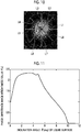
- Fig. 7 is a diagram showing an example of a phase difference image captured by the imaging unit 40 before adjustment by the adjustment optical system 20.
- the liquid surface shape estimation unit 54 sets a straight line L, which extends from the central portion of the meniscus toward the outer periphery of the culture container 60, on the phase difference image captured by the imaging unit 40, and acquires the brightness distribution of the phase difference image on the set straight line L.
- the extension direction of the straight line L set herein is the same as the extension direction of the straight line set on the phase difference image in the case of acquiring the brightness distribution in the geometric optical simulation.
- smoothing processing such as low pass filter processing, may be performed on the phase difference image before acquiring the brightness distribution of the phase difference image as described above, and the brightness distribution of the phase difference image subjected to the smoothing processing may be acquired.
- smoothing processing such as low pass filter processing
- the liquid surface shape estimation unit 54 specifies the central portion of the meniscus based on the brightness of the phase difference image. Specifically, the central portion of the meniscus is specified, for example, by extracting a region having a brightness equal to or less than a threshold value set in advance from the phase difference image and specifying a circular region close to the central portion of the phase difference image in the extracted region. Then, by setting a straight line extending from the center position in the specified central portion of the meniscus toward the outside, the straight line L shown in Fig. 7 is set.
- the correlation between the brightness distributions may be calculated by using a correlation function.
- a correlation function for example, as indicated by an arrow in Fig. 8
- inflection points in the brightness distribution of the liquid surface shape stored in advance and the brightness distribution of the phase difference image captured by the imaging unit 40 are obtained, and the total value of the differences of the brightness values (optical densities) of the corresponding inflection points of the brightness distributions is calculated.
- the above-described total value may be calculated for each of the brightness distributions of a plurality of liquid surface shapes stored in advance, and the brightness distribution having the smallest total value may be specified as a brightness distribution having the highest correlation.
- the liquid surface shape estimation unit 54 specifies a liquid surface shape of the curvature having the highest correlation with the brightness distribution of the phase difference image captured by the imaging unit 40, and estimates the specified liquid surface shape of the curvature as the liquid surface shape of the culture solution C in the culture container 60.
- the adjustment information acquisition unit 55 acquires adjustment information for adjusting the optical characteristics of the adjustment optical system 20 based on the liquid surface shape estimated by the liquid surface shape estimation unit 54 as described above. Specifically, the adjustment information acquisition unit 55 of the present embodiment acquires the inclination angle of the liquid surface in the imaging region of the phase difference image based on the liquid surface shape estimated by the liquid surface shape estimation unit 54, and calculates the refraction angle of illumination light in the imaging region based on the inclination angle and the refractive index of the culture solution C.
- the inside of the culture container 60 is scanned with illumination light as described above, and a phase difference image is captured for each of a plurality of imaging regions obtained by dividing the inside of the culture container 60. Accordingly, the refraction angle of illumination light is calculated for each imaging region.
- the adjustment information acquisition unit 55 outputs information of the refraction angle of the illumination light in each imaging region to the adjustment optical system control unit 51 as adjustment information.
- the adjustment optical system control unit 51 adjusts the optical characteristics of the adjustment optical system 20 based on the information on the refraction angle of the illumination light calculated by the adjustment information acquisition unit 55. Specifically, a look-up table in which the refraction angle of the illumination light in the imaging region is associated with the amount of adjustment of the adjustment optical element 21 of the adjustment optical system 20 is set in advance in the adjustment optical system control unit 51. Then, based on the information of the refraction angle of the illumination light, the adjustment optical system control unit 51 acquires the amount of adjustment of the adjustment optical element 21 of the adjustment optical system 20 with reference to the look-up table described above, and outputs a control signal corresponding to the amount of adjustment to the adjustment optical system driving unit 22. As the amount of adjustment of the adjustment optical element 21 of the adjustment optical system 20, as described above, there are positions in the X, Y, and Z directions, focal power, optical axis direction, and the like of the adjustment optical element 21.
- the control signal output from the adjustment optical system control unit 51 is input to the adjustment optical system driving unit 22, and the adjustment optical system driving unit 22 adjusts the optical characteristics by adjusting the focal power, positions in the X, Y, and Z directions, and optical axis direction of the adjustment optical element 21 based on the input control signal.
- the adjustment information acquisition unit 55 acquires, as adjustment information, information specifying the type of the adjustment optical element 21 having the optical characteristics corresponding to the liquid surface shape estimated by the liquid surface shape estimation unit 54. It is assumed that a table, in which the liquid surface shape is associated with the information specifying the type of the adjustment optical element 21 corresponding to the liquid surface shape, is set in advance in the adjustment information acquisition unit 55.
- the information specifying the type of the adjustment optical element 21 acquired by the adjustment information acquisition unit 55 is output to the adjustment optical system control unit 51, and the adjustment optical system control unit 51 performs automatic switching to the adjustment optical element 21 corresponding to the liquid surface shape based on the input information.
- the information specifying the type of the adjustment optical element 21 may be displayed on the display device 70 to notify the user of the information, so that the user manually replaces the adjustment optical element 21.
- the imaging optical system control unit 52 controls the driving of the imaging optical system driving unit 34 to move the objective lens 31 in the Z direction. Specifically, the imaging optical system control unit 52 of the present embodiment performs autofocus control by moving the objective lens 31 in the Z direction using the imaging optical system driving unit 34 in the case of capturing the phase difference image.
- the stage control unit 53 controls the driving of the stage driving unit 62 to move the stage 61 in the X, Y, and Z directions.
- the stage control unit 53 moves the stage 61 in the X and Y directions as described above to scan the inside of the culture container 60 with illumination light, so that a phase difference image is captured for each of a plurality of imaging regions divided within the culture container 60 (for example, within one well).
- the input device 80 and the display device 70 are connected to the microscope control device 50.
- the input device 80 includes an input device, such as a keyboard or a mouse, and receives a setting input from the user.
- the display device 70 is a display device, such as a liquid crystal display, and displays a phase difference image or the like captured by the imaging unit 40.
- the display device 70 may be configured by a touch panel so that the display device 70 also serves as an input device.
- the culture container 60 in which the observation target S and the culture solution C are contained is placed on the stage 61. Then, a phase difference image of the observation target S before adjustment by the adjustment optical system 20 is captured and acquired by the liquid surface shape estimation unit 54 (S10).
- the liquid surface shape estimation unit 54 sets the straight line L, which extends from the central portion of the meniscus toward the outer periphery of the culture container 60, on the phase difference image before adjustment as described above, and acquires the brightness distribution of the phase difference image on the set straight line L (S12).
- the estimation result of the liquid surface shape is output to the adjustment information acquisition unit 55, and the adjustment information acquisition unit 55 acquires adjustment information for adjusting the optical characteristics of the adjustment optical system 20 based on the estimated liquid surface shape (S16).
- the adjustment information acquired by the adjustment information acquisition unit 55 is output to the adjustment optical system control unit 51, and the adjustment optical system control unit 51 adjusts the optical characteristics of the adjustment optical system 20 based on the input adjustment information (S18).
- the phase difference image of the observation target S is captured again by the imaging unit 40 (S20).
- the phase difference image captured by the imaging unit 40 is output to the display device 70 and displayed by the display device 70.
- the liquid surface shape of the culture solution C in the culture container 60 is estimated based on the brightness distribution of the phase difference image captured by the imaging unit 40 that captures a phase difference image for observation. Therefore, it is possible to estimate the liquid surface shape of the culture solution C in the culture container 60 without providing a new measurement system for estimating the liquid surface shape. Then, since the optical characteristics of the adjustment optical system 20 are adjusted based on the estimated liquid surface shape and then the phase difference image of the observation target is captured, it is possible to capture a phase difference image in which the influence of the meniscus is suppressed.
- one straight line L extending from the central portion of the meniscus toward the outer periphery of the culture container 60 is set on the phase difference image captured by the imaging unit 40, and the brightness distribution on the straight line L is used as a representative of the brightness distribution of the entire phase difference image.
- a plurality of straight lines extending from the central portion of the meniscus toward the outer periphery may be set. That is, the meniscus formed in the culture container 60 is not necessarily formed with the same curvature in each direction from the center toward the outer periphery of the culture container 60.
- Fig. 10 eight straight lines L1 to L8 extending from the central portion of the meniscus toward the outer periphery may be set, and the brightness distribution for each straight line may be acquired. Then, by calculating the curvature of the liquid surface shape corresponding to the brightness distribution for each straight line, the curvature of the liquid surface shape may be obtained for each of the eight directions. As a result, it is possible to estimate the liquid surface shape with higher accuracy.
- an average value or a mode value of these curvatures may be calculated as a representative value, and adjustment information of the adjustment optical system 20 may be acquired based on the curvature of the representative value.
- the adjustment information of the adjustment optical system 20 may be acquired for each region divided for each direction using the curvature obtained for each direction. As a method of dividing a region for each direction, for example, division into fan-shaped regions each including a straight line extending in each direction at the center of the circular arc may be applied.
- the curvature R of the liquid surface shape is calculated on the assumption that the liquid surface shape is close to a spherical shape.
- the liquid surface shape does not become a spherical shape. For this reason, there is a possibility that the estimation accuracy of the liquid surface shape will be lowered. Therefore, the liquid surface shape may be estimated as follows.
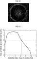
- a profile shown in Fig. 11 is acquired in which a brightness value P(x) of the phase difference image and the inclination angle ⁇ of the liquid surface are associated with each other.
- the brightness value P(x) indicates a brightness value at each position x between the central portion of the meniscus model M to the outer periphery of the culture container model 60a.
- the inclination angle ⁇ of the liquid surface is the inclination angle ⁇ 1 shown in Fig. 4 .
- the profile shown in Fig. 11 can be acquired using the calculation result in the embodiment described above.
- the phase difference image captured by the imaging unit 40 is acquired, the phase difference image is normalized so that the brightness value of the central portion of the meniscus becomes 1, and smoothing processing is performed on the normalized phase difference image to remove high frequency noise originating from cells.
- a straight line extending from the central portion of the meniscus toward the outer periphery is set as shown in Fig. 12 .
- brightness values at respective positions x 1 , x 2 , ..., x n are acquired.
- the profile shown in Fig. 11 the inclination angle ⁇ of the liquid surface corresponding to the brightness value P(x) at each position x is calculated.
- it is possible to calculate the inclination angle ⁇ of the liquid surface at each position on the straight line shown in Fig. 12 it is possible to estimate the shape of the liquid surface on the straight line.
- the inclination angle of the liquid surface may be set to increase as the distance from the center of the meniscus increases.
- the smallest inclination angle ⁇ may be selected first.
- the adjustment optical element 21 is provided to eliminate the influence of the refraction of illumination light due to the meniscus formed on the liquid surface.
- an adjustment optical element 21 does not necessarily need to be provided.
- the influence of the refraction of illumination light due to the meniscus may be eliminated by moving the slit plate 12 in the X and Y directions based on the adjustment information or by moving the phase plate 32 in the X and Y directions based on the adjustment information. That is, the slit plate 12 or the phase plate 32 may be used as the adjustment optical system in the present invention.
- the adjustment optical element 21 is provided between the condenser lens 13 and the culture container 60.
- the position of the adjustment optical element 21 is not limited thereto.
- the adjustment optical element 21 may be provided at other positions, such as between the white light source 11 and the slit plate 12, between the phase plate 32 and the condenser lens 13, and between the culture container 60 and the objective lens 31.
Applications Claiming Priority (2)
| Application Number | Priority Date | Filing Date | Title |
|---|---|---|---|
| JP2016030705A JP6594223B2 (ja) | 2016-02-22 | 2016-02-22 | 位相差顕微鏡および撮像方法 |
| PCT/JP2017/005128 WO2017145839A1 (ja) | 2016-02-22 | 2017-02-13 | 位相差顕微鏡および撮像方法 |
Publications (3)
| Publication Number | Publication Date |
|---|---|
| EP3422073A1 EP3422073A1 (en) | 2019-01-02 |
| EP3422073A4 EP3422073A4 (en) | 2019-03-06 |
| EP3422073B1 true EP3422073B1 (en) | 2020-04-22 |
Family
ID=59685125
Family Applications (1)
| Application Number | Title | Priority Date | Filing Date |
|---|---|---|---|
| EP17756280.8A Active EP3422073B1 (en) | 2016-02-22 | 2017-02-13 | Phase-contrast microscope and imaging method |
Country Status (5)
| Country | Link |
|---|---|
| US (1) | US10831009B2 (ja) |
| EP (1) | EP3422073B1 (ja) |
| JP (1) | JP6594223B2 (ja) |
| KR (1) | KR102054095B1 (ja) |
| WO (1) | WO2017145839A1 (ja) |
Families Citing this family (4)
| Publication number | Priority date | Publication date | Assignee | Title |
|---|---|---|---|---|
| JP6411294B2 (ja) * | 2015-06-30 | 2018-10-24 | 富士フイルム株式会社 | 位相差顕微鏡および撮像方法 |
| KR20200019250A (ko) | 2017-08-25 | 2020-02-21 | 후지필름 가부시키가이샤 | 판별기의 학습 장치, 방법 및 프로그램과, 판별기 |
| KR20220102324A (ko) * | 2021-01-12 | 2022-07-20 | 정홍준 | 투명 디스플레이 패널을 이용한 현미경의 투과광 형성장치 |
| CN113532800A (zh) * | 2021-05-21 | 2021-10-22 | 杭州涂鸦信息技术有限公司 | 透光区域的分析方法以及相关设备、装置 |
Family Cites Families (10)
| Publication number | Priority date | Publication date | Assignee | Title |
|---|---|---|---|---|
| EP2140267B1 (en) * | 2007-02-26 | 2017-11-15 | StemCell Technologies Inc. | Method of reducing curvature in a meniscus of liquid medium |
| JP5556444B2 (ja) * | 2010-06-30 | 2014-07-23 | 株式会社ニコン | 顕微鏡、培養観察装置 |
| JP5814684B2 (ja) * | 2010-09-03 | 2015-11-17 | オリンパス株式会社 | 位相物体の可視化方法及び可視化装置 |
| JP5008763B2 (ja) * | 2010-12-03 | 2012-08-22 | キヤノン株式会社 | 屈折率分布計測方法、屈折率分布計測装置および光学素子の製造方法 |
| US9069175B2 (en) * | 2011-04-08 | 2015-06-30 | Kairos Instruments, Llc | Adaptive phase contrast microscope |
| JP5946751B2 (ja) * | 2012-11-08 | 2016-07-06 | 株式会社日立ハイテクノロジーズ | 欠陥検出方法及びその装置並びに欠陥観察方法及びその装置 |
| JP2015152649A (ja) * | 2014-02-12 | 2015-08-24 | 株式会社ニコン | 位相差顕微鏡 |
| JP2015152650A (ja) | 2014-02-12 | 2015-08-24 | 株式会社ニコン | 位相差顕微鏡 |
| JP6380983B2 (ja) * | 2014-11-26 | 2018-08-29 | 富士フイルム株式会社 | 位相差顕微鏡 |
| JP6513507B2 (ja) * | 2015-06-30 | 2019-05-15 | 富士フイルム株式会社 | 位相差顕微鏡および撮像方法 |
-
2016
- 2016-02-22 JP JP2016030705A patent/JP6594223B2/ja active Active
-
2017
- 2017-02-13 EP EP17756280.8A patent/EP3422073B1/en active Active
- 2017-02-13 WO PCT/JP2017/005128 patent/WO2017145839A1/ja active Application Filing
- 2017-02-13 KR KR1020187022710A patent/KR102054095B1/ko active IP Right Grant
-
2018
- 2018-08-02 US US16/053,509 patent/US10831009B2/en active Active
Non-Patent Citations (1)
| Title |
|---|
| None * |
Also Published As
| Publication number | Publication date |
|---|---|
| EP3422073A1 (en) | 2019-01-02 |
| EP3422073A4 (en) | 2019-03-06 |
| WO2017145839A1 (ja) | 2017-08-31 |
| US10831009B2 (en) | 2020-11-10 |
| US20190033569A1 (en) | 2019-01-31 |
| KR102054095B1 (ko) | 2019-12-09 |
| JP2017151132A (ja) | 2017-08-31 |
| KR20180102118A (ko) | 2018-09-14 |
| JP6594223B2 (ja) | 2019-10-23 |
Similar Documents
| Publication | Publication Date | Title |
|---|---|---|
| US10831009B2 (en) | Phase contrast microscope and imaging method | |
| EP3318912B1 (en) | Phase contrast microscope and imaging method | |
| JP6380983B2 (ja) | 位相差顕微鏡 | |
| EP3336171B1 (en) | Cell evaluation device | |
| US8831306B2 (en) | Flow type particle image analysis method and device | |
| JP2015092253A (ja) | 適応光学系を有する顕微鏡検査法 | |
| JP6513507B2 (ja) | 位相差顕微鏡および撮像方法 | |
| JP2013113696A (ja) | 変位測定方法および変位測定装置 | |
| CN106895793A (zh) | 双模式深度测量的方法与装置 | |
| EP3422074A1 (en) | Microscope and observation method | |
| JP2010183028A (ja) | パターン描画装置およびパターン描画方法 | |
| CN104880913A (zh) | 一种提高工艺适应性的调焦调平系统 | |
| TWI715812B (zh) | 在半導體製造中之目標位置 | |
| JP2013002968A (ja) | 部品高さ測定方法およびその装置 | |
| KR101167071B1 (ko) | 닙코우 디스크의 핀홀 배치 방법 | |
| JP2010121955A (ja) | 高さ情報取得装置、高さ情報取得方法、及びプログラム | |
| KR101826226B1 (ko) | 자동 보정 집광렌즈를 이용한 자동으로 초점을 조절하는 방법 및 장치 | |
| US6490031B1 (en) | Radiometric scatter monitor | |
| JP2015210396A (ja) | アライメント装置、顕微鏡システム、アライメント方法、及びアライメントプログラム | |
| KR20180104041A (ko) | 세포 관찰 장치 및 방법 | |
| EP3835721A1 (en) | A method for measuring a height map of a test surface | |
| KR20230149932A (ko) | 초점 거리 측정 장치 및 방법 |
Legal Events
| Date | Code | Title | Description |
|---|---|---|---|
| STAA | Information on the status of an ep patent application or granted ep patent |
Free format text: STATUS: THE INTERNATIONAL PUBLICATION HAS BEEN MADE |
|
| PUAI | Public reference made under article 153(3) epc to a published international application that has entered the european phase |
Free format text: ORIGINAL CODE: 0009012 |
|
| STAA | Information on the status of an ep patent application or granted ep patent |
Free format text: STATUS: REQUEST FOR EXAMINATION WAS MADE |
|
| 17P | Request for examination filed |
Effective date: 20180726 |
|
| AK | Designated contracting states |
Kind code of ref document: A1 Designated state(s): AL AT BE BG CH CY CZ DE DK EE ES FI FR GB GR HR HU IE IS IT LI LT LU LV MC MK MT NL NO PL PT RO RS SE SI SK SM TR |
|
| AX | Request for extension of the european patent |
Extension state: BA ME |
|
| A4 | Supplementary search report drawn up and despatched |
Effective date: 20190204 |
|
| RIC1 | Information provided on ipc code assigned before grant |
Ipc: G02B 26/06 20060101ALI20190129BHEP Ipc: G02B 21/14 20060101ALI20190129BHEP Ipc: G02B 26/08 20060101ALI20190129BHEP Ipc: G02B 21/36 20060101ALI20190129BHEP Ipc: G02B 27/00 20060101ALI20190129BHEP Ipc: G02B 21/08 20060101ALI20190129BHEP Ipc: G02B 21/06 20060101AFI20190129BHEP Ipc: G02B 3/14 20060101ALI20190129BHEP |
|
| DAV | Request for validation of the european patent (deleted) | ||
| DAX | Request for extension of the european patent (deleted) | ||
| RIC1 | Information provided on ipc code assigned before grant |
Ipc: G02B 26/08 20060101ALI20190930BHEP Ipc: G02B 21/06 20060101AFI20190930BHEP Ipc: G02B 3/14 20060101ALI20190930BHEP Ipc: G02B 21/36 20060101ALI20190930BHEP Ipc: G02B 21/08 20060101ALI20190930BHEP Ipc: G02B 27/00 20060101ALI20190930BHEP Ipc: G02B 26/06 20060101ALI20190930BHEP Ipc: G02B 21/14 20060101ALI20190930BHEP |
|
| GRAP | Despatch of communication of intention to grant a patent |
Free format text: ORIGINAL CODE: EPIDOSNIGR1 |
|
| STAA | Information on the status of an ep patent application or granted ep patent |
Free format text: STATUS: GRANT OF PATENT IS INTENDED |
|
| INTG | Intention to grant announced |
Effective date: 20191115 |
|
| GRAJ | Information related to disapproval of communication of intention to grant by the applicant or resumption of examination proceedings by the epo deleted |
Free format text: ORIGINAL CODE: EPIDOSDIGR1 |
|
| STAA | Information on the status of an ep patent application or granted ep patent |
Free format text: STATUS: REQUEST FOR EXAMINATION WAS MADE |
|
| GRAR | Information related to intention to grant a patent recorded |
Free format text: ORIGINAL CODE: EPIDOSNIGR71 |
|
| GRAS | Grant fee paid |
Free format text: ORIGINAL CODE: EPIDOSNIGR3 |
|
| STAA | Information on the status of an ep patent application or granted ep patent |
Free format text: STATUS: GRANT OF PATENT IS INTENDED |
|
| GRAA | (expected) grant |
Free format text: ORIGINAL CODE: 0009210 |
|
| STAA | Information on the status of an ep patent application or granted ep patent |
Free format text: STATUS: THE PATENT HAS BEEN GRANTED |
|
| INTC | Intention to grant announced (deleted) | ||
| INTG | Intention to grant announced |
Effective date: 20200312 |
|
| AK | Designated contracting states |
Kind code of ref document: B1 Designated state(s): AL AT BE BG CH CY CZ DE DK EE ES FI FR GB GR HR HU IE IS IT LI LT LU LV MC MK MT NL NO PL PT RO RS SE SI SK SM TR |
|
| REG | Reference to a national code |
Ref country code: CH Ref legal event code: EP |
|
| REG | Reference to a national code |
Ref country code: IE Ref legal event code: FG4D |
|
| REG | Reference to a national code |
Ref country code: DE Ref legal event code: R096 Ref document number: 602017015341 Country of ref document: DE |
|
| REG | Reference to a national code |
Ref country code: AT Ref legal event code: REF Ref document number: 1260885 Country of ref document: AT Kind code of ref document: T Effective date: 20200515 |
|
| REG | Reference to a national code |
Ref country code: CH Ref legal event code: NV Representative=s name: SERVOPATENT GMBH, CH |
|
| REG | Reference to a national code |
Ref country code: LT Ref legal event code: MG4D |
|
| REG | Reference to a national code |
Ref country code: NL Ref legal event code: MP Effective date: 20200422 |
|
| PG25 | Lapsed in a contracting state [announced via postgrant information from national office to epo] |
Ref country code: SE Free format text: LAPSE BECAUSE OF FAILURE TO SUBMIT A TRANSLATION OF THE DESCRIPTION OR TO PAY THE FEE WITHIN THE PRESCRIBED TIME-LIMIT Effective date: 20200422 Ref country code: NO Free format text: LAPSE BECAUSE OF FAILURE TO SUBMIT A TRANSLATION OF THE DESCRIPTION OR TO PAY THE FEE WITHIN THE PRESCRIBED TIME-LIMIT Effective date: 20200722 Ref country code: FI Free format text: LAPSE BECAUSE OF FAILURE TO SUBMIT A TRANSLATION OF THE DESCRIPTION OR TO PAY THE FEE WITHIN THE PRESCRIBED TIME-LIMIT Effective date: 20200422 Ref country code: GR Free format text: LAPSE BECAUSE OF FAILURE TO SUBMIT A TRANSLATION OF THE DESCRIPTION OR TO PAY THE FEE WITHIN THE PRESCRIBED TIME-LIMIT Effective date: 20200723 Ref country code: IS Free format text: LAPSE BECAUSE OF FAILURE TO SUBMIT A TRANSLATION OF THE DESCRIPTION OR TO PAY THE FEE WITHIN THE PRESCRIBED TIME-LIMIT Effective date: 20200822 Ref country code: PT Free format text: LAPSE BECAUSE OF FAILURE TO SUBMIT A TRANSLATION OF THE DESCRIPTION OR TO PAY THE FEE WITHIN THE PRESCRIBED TIME-LIMIT Effective date: 20200824 Ref country code: LT Free format text: LAPSE BECAUSE OF FAILURE TO SUBMIT A TRANSLATION OF THE DESCRIPTION OR TO PAY THE FEE WITHIN THE PRESCRIBED TIME-LIMIT Effective date: 20200422 Ref country code: NL Free format text: LAPSE BECAUSE OF FAILURE TO SUBMIT A TRANSLATION OF THE DESCRIPTION OR TO PAY THE FEE WITHIN THE PRESCRIBED TIME-LIMIT Effective date: 20200422 |
|
| REG | Reference to a national code |
Ref country code: AT Ref legal event code: MK05 Ref document number: 1260885 Country of ref document: AT Kind code of ref document: T Effective date: 20200422 |
|
| PG25 | Lapsed in a contracting state [announced via postgrant information from national office to epo] |
Ref country code: LV Free format text: LAPSE BECAUSE OF FAILURE TO SUBMIT A TRANSLATION OF THE DESCRIPTION OR TO PAY THE FEE WITHIN THE PRESCRIBED TIME-LIMIT Effective date: 20200422 Ref country code: HR Free format text: LAPSE BECAUSE OF FAILURE TO SUBMIT A TRANSLATION OF THE DESCRIPTION OR TO PAY THE FEE WITHIN THE PRESCRIBED TIME-LIMIT Effective date: 20200422 Ref country code: BG Free format text: LAPSE BECAUSE OF FAILURE TO SUBMIT A TRANSLATION OF THE DESCRIPTION OR TO PAY THE FEE WITHIN THE PRESCRIBED TIME-LIMIT Effective date: 20200722 Ref country code: RS Free format text: LAPSE BECAUSE OF FAILURE TO SUBMIT A TRANSLATION OF THE DESCRIPTION OR TO PAY THE FEE WITHIN THE PRESCRIBED TIME-LIMIT Effective date: 20200422 |
|
| PG25 | Lapsed in a contracting state [announced via postgrant information from national office to epo] |
Ref country code: AL Free format text: LAPSE BECAUSE OF FAILURE TO SUBMIT A TRANSLATION OF THE DESCRIPTION OR TO PAY THE FEE WITHIN THE PRESCRIBED TIME-LIMIT Effective date: 20200422 |
|
| REG | Reference to a national code |
Ref country code: DE Ref legal event code: R097 Ref document number: 602017015341 Country of ref document: DE |
|
| PG25 | Lapsed in a contracting state [announced via postgrant information from national office to epo] |
Ref country code: SM Free format text: LAPSE BECAUSE OF FAILURE TO SUBMIT A TRANSLATION OF THE DESCRIPTION OR TO PAY THE FEE WITHIN THE PRESCRIBED TIME-LIMIT Effective date: 20200422 Ref country code: EE Free format text: LAPSE BECAUSE OF FAILURE TO SUBMIT A TRANSLATION OF THE DESCRIPTION OR TO PAY THE FEE WITHIN THE PRESCRIBED TIME-LIMIT Effective date: 20200422 Ref country code: DK Free format text: LAPSE BECAUSE OF FAILURE TO SUBMIT A TRANSLATION OF THE DESCRIPTION OR TO PAY THE FEE WITHIN THE PRESCRIBED TIME-LIMIT Effective date: 20200422 Ref country code: AT Free format text: LAPSE BECAUSE OF FAILURE TO SUBMIT A TRANSLATION OF THE DESCRIPTION OR TO PAY THE FEE WITHIN THE PRESCRIBED TIME-LIMIT Effective date: 20200422 Ref country code: CZ Free format text: LAPSE BECAUSE OF FAILURE TO SUBMIT A TRANSLATION OF THE DESCRIPTION OR TO PAY THE FEE WITHIN THE PRESCRIBED TIME-LIMIT Effective date: 20200422 Ref country code: RO Free format text: LAPSE BECAUSE OF FAILURE TO SUBMIT A TRANSLATION OF THE DESCRIPTION OR TO PAY THE FEE WITHIN THE PRESCRIBED TIME-LIMIT Effective date: 20200422 Ref country code: ES Free format text: LAPSE BECAUSE OF FAILURE TO SUBMIT A TRANSLATION OF THE DESCRIPTION OR TO PAY THE FEE WITHIN THE PRESCRIBED TIME-LIMIT Effective date: 20200422 Ref country code: IT Free format text: LAPSE BECAUSE OF FAILURE TO SUBMIT A TRANSLATION OF THE DESCRIPTION OR TO PAY THE FEE WITHIN THE PRESCRIBED TIME-LIMIT Effective date: 20200422 |
|
| PG25 | Lapsed in a contracting state [announced via postgrant information from national office to epo] |
Ref country code: PL Free format text: LAPSE BECAUSE OF FAILURE TO SUBMIT A TRANSLATION OF THE DESCRIPTION OR TO PAY THE FEE WITHIN THE PRESCRIBED TIME-LIMIT Effective date: 20200422 Ref country code: SK Free format text: LAPSE BECAUSE OF FAILURE TO SUBMIT A TRANSLATION OF THE DESCRIPTION OR TO PAY THE FEE WITHIN THE PRESCRIBED TIME-LIMIT Effective date: 20200422 |
|
| PLBE | No opposition filed within time limit |
Free format text: ORIGINAL CODE: 0009261 |
|
| STAA | Information on the status of an ep patent application or granted ep patent |
Free format text: STATUS: NO OPPOSITION FILED WITHIN TIME LIMIT |
|
| 26N | No opposition filed |
Effective date: 20210125 |
|
| PG25 | Lapsed in a contracting state [announced via postgrant information from national office to epo] |
Ref country code: SI Free format text: LAPSE BECAUSE OF FAILURE TO SUBMIT A TRANSLATION OF THE DESCRIPTION OR TO PAY THE FEE WITHIN THE PRESCRIBED TIME-LIMIT Effective date: 20200422 |
|
| PG25 | Lapsed in a contracting state [announced via postgrant information from national office to epo] |
Ref country code: MC Free format text: LAPSE BECAUSE OF FAILURE TO SUBMIT A TRANSLATION OF THE DESCRIPTION OR TO PAY THE FEE WITHIN THE PRESCRIBED TIME-LIMIT Effective date: 20200422 |
|
| GBPC | Gb: european patent ceased through non-payment of renewal fee |
Effective date: 20210213 |
|
| REG | Reference to a national code |
Ref country code: BE Ref legal event code: MM Effective date: 20210228 |
|
| PG25 | Lapsed in a contracting state [announced via postgrant information from national office to epo] |
Ref country code: LU Free format text: LAPSE BECAUSE OF NON-PAYMENT OF DUE FEES Effective date: 20210213 |
|
| PG25 | Lapsed in a contracting state [announced via postgrant information from national office to epo] |
Ref country code: FR Free format text: LAPSE BECAUSE OF NON-PAYMENT OF DUE FEES Effective date: 20210228 Ref country code: GB Free format text: LAPSE BECAUSE OF NON-PAYMENT OF DUE FEES Effective date: 20210213 Ref country code: IE Free format text: LAPSE BECAUSE OF NON-PAYMENT OF DUE FEES Effective date: 20210213 |
|
| PG25 | Lapsed in a contracting state [announced via postgrant information from national office to epo] |
Ref country code: BE Free format text: LAPSE BECAUSE OF NON-PAYMENT OF DUE FEES Effective date: 20210228 |
|
| PGFP | Annual fee paid to national office [announced via postgrant information from national office to epo] |
Ref country code: CH Payment date: 20230307 Year of fee payment: 7 |
|
| PGFP | Annual fee paid to national office [announced via postgrant information from national office to epo] |
Ref country code: DE Payment date: 20221229 Year of fee payment: 7 |
|
| P01 | Opt-out of the competence of the unified patent court (upc) registered |
Effective date: 20230515 |
|
| PG25 | Lapsed in a contracting state [announced via postgrant information from national office to epo] |
Ref country code: CY Free format text: LAPSE BECAUSE OF FAILURE TO SUBMIT A TRANSLATION OF THE DESCRIPTION OR TO PAY THE FEE WITHIN THE PRESCRIBED TIME-LIMIT Effective date: 20200422 |
|
| PG25 | Lapsed in a contracting state [announced via postgrant information from national office to epo] |
Ref country code: HU Free format text: LAPSE BECAUSE OF FAILURE TO SUBMIT A TRANSLATION OF THE DESCRIPTION OR TO PAY THE FEE WITHIN THE PRESCRIBED TIME-LIMIT; INVALID AB INITIO Effective date: 20170213 |