WO2017145839A1 - 位相差顕微鏡および撮像方法 - Google Patents
位相差顕微鏡および撮像方法 Download PDFInfo
- Publication number
- WO2017145839A1 WO2017145839A1 PCT/JP2017/005128 JP2017005128W WO2017145839A1 WO 2017145839 A1 WO2017145839 A1 WO 2017145839A1 JP 2017005128 W JP2017005128 W JP 2017005128W WO 2017145839 A1 WO2017145839 A1 WO 2017145839A1
- Authority
- WO
- WIPO (PCT)
- Prior art keywords
- surface shape
- liquid surface
- liquid
- phase difference
- difference image
- Prior art date
Links
- 238000003384 imaging method Methods 0.000 title claims abstract description 80
- 239000007788 liquid Substances 0.000 claims abstract description 206
- 230000003287 optical effect Effects 0.000 claims abstract description 174
- 238000009826 distribution Methods 0.000 claims abstract description 76
- 238000005286 illumination Methods 0.000 claims abstract description 64
- 238000005259 measurement Methods 0.000 claims abstract description 18
- 230000005499 meniscus Effects 0.000 claims description 60
- 238000013041 optical simulation Methods 0.000 claims description 22
- 238000000034 method Methods 0.000 claims description 16
- 238000009499 grossing Methods 0.000 claims description 8
- 230000008569 process Effects 0.000 claims description 6
- 238000005314 correlation function Methods 0.000 claims description 4
- 230000001678 irradiating effect Effects 0.000 claims description 4
- 239000001963 growth medium Substances 0.000 description 12
- 230000008859 change Effects 0.000 description 7
- 238000010586 diagram Methods 0.000 description 7
- 210000004027 cell Anatomy 0.000 description 6
- 239000004973 liquid crystal related substance Substances 0.000 description 6
- 230000009471 action Effects 0.000 description 4
- 238000009434 installation Methods 0.000 description 4
- LFQSCWFLJHTTHZ-UHFFFAOYSA-N Ethanol Chemical compound CCO LFQSCWFLJHTTHZ-UHFFFAOYSA-N 0.000 description 3
- OKKJLVBELUTLKV-UHFFFAOYSA-N Methanol Chemical compound OC OKKJLVBELUTLKV-UHFFFAOYSA-N 0.000 description 3
- 238000004364 calculation method Methods 0.000 description 3
- 230000000694 effects Effects 0.000 description 3
- XLYOFNOQVPJJNP-UHFFFAOYSA-N water Substances O XLYOFNOQVPJJNP-UHFFFAOYSA-N 0.000 description 3
- WSFSSNUMVMOOMR-UHFFFAOYSA-N Formaldehyde Chemical compound O=C WSFSSNUMVMOOMR-UHFFFAOYSA-N 0.000 description 2
- 230000007246 mechanism Effects 0.000 description 2
- 240000006829 Ficus sundaica Species 0.000 description 1
- 230000002238 attenuated effect Effects 0.000 description 1
- 230000000295 complement effect Effects 0.000 description 1
- 210000004748 cultured cell Anatomy 0.000 description 1
- 230000008020 evaporation Effects 0.000 description 1
- 238000001704 evaporation Methods 0.000 description 1
- 239000000463 material Substances 0.000 description 1
- 229910044991 metal oxide Inorganic materials 0.000 description 1
- 150000004706 metal oxides Chemical class 0.000 description 1
- 230000007935 neutral effect Effects 0.000 description 1
- 239000004065 semiconductor Substances 0.000 description 1
- 238000010186 staining Methods 0.000 description 1
- 210000000130 stem cell Anatomy 0.000 description 1
- 238000002834 transmittance Methods 0.000 description 1
Images


Classifications
-
- G—PHYSICS
- G02—OPTICS
- G02B—OPTICAL ELEMENTS, SYSTEMS OR APPARATUS
- G02B21/00—Microscopes
- G02B21/06—Means for illuminating specimens
-
- G—PHYSICS
- G02—OPTICS
- G02B—OPTICAL ELEMENTS, SYSTEMS OR APPARATUS
- G02B21/00—Microscopes
- G02B21/06—Means for illuminating specimens
- G02B21/08—Condensers
- G02B21/14—Condensers affording illumination for phase-contrast observation
-
- G—PHYSICS
- G02—OPTICS
- G02B—OPTICAL ELEMENTS, SYSTEMS OR APPARATUS
- G02B21/00—Microscopes
- G02B21/06—Means for illuminating specimens
- G02B21/08—Condensers
- G02B21/086—Condensers for transillumination only
-
- G—PHYSICS
- G02—OPTICS
- G02B—OPTICAL ELEMENTS, SYSTEMS OR APPARATUS
- G02B21/00—Microscopes
- G02B21/36—Microscopes arranged for photographic purposes or projection purposes or digital imaging or video purposes including associated control and data processing arrangements
-
- G—PHYSICS
- G02—OPTICS
- G02B—OPTICAL ELEMENTS, SYSTEMS OR APPARATUS
- G02B21/00—Microscopes
- G02B21/36—Microscopes arranged for photographic purposes or projection purposes or digital imaging or video purposes including associated control and data processing arrangements
- G02B21/365—Control or image processing arrangements for digital or video microscopes
-
- G—PHYSICS
- G02—OPTICS
- G02B—OPTICAL ELEMENTS, SYSTEMS OR APPARATUS
- G02B26/00—Optical devices or arrangements for the control of light using movable or deformable optical elements
- G02B26/06—Optical devices or arrangements for the control of light using movable or deformable optical elements for controlling the phase of light
-
- G—PHYSICS
- G02—OPTICS
- G02B—OPTICAL ELEMENTS, SYSTEMS OR APPARATUS
- G02B26/00—Optical devices or arrangements for the control of light using movable or deformable optical elements
- G02B26/08—Optical devices or arrangements for the control of light using movable or deformable optical elements for controlling the direction of light
- G02B26/0875—Optical devices or arrangements for the control of light using movable or deformable optical elements for controlling the direction of light by means of one or more refracting elements
-
- G—PHYSICS
- G02—OPTICS
- G02B—OPTICAL ELEMENTS, SYSTEMS OR APPARATUS
- G02B27/00—Optical systems or apparatus not provided for by any of the groups G02B1/00 - G02B26/00, G02B30/00
- G02B27/0025—Optical systems or apparatus not provided for by any of the groups G02B1/00 - G02B26/00, G02B30/00 for optical correction, e.g. distorsion, aberration
- G02B27/0068—Optical systems or apparatus not provided for by any of the groups G02B1/00 - G02B26/00, G02B30/00 for optical correction, e.g. distorsion, aberration having means for controlling the degree of correction, e.g. using phase modulators, movable elements
-
- G—PHYSICS
- G02—OPTICS
- G02B—OPTICAL ELEMENTS, SYSTEMS OR APPARATUS
- G02B3/00—Simple or compound lenses
- G02B3/12—Fluid-filled or evacuated lenses
- G02B3/14—Fluid-filled or evacuated lenses of variable focal length
-
- G—PHYSICS
- G06—COMPUTING; CALCULATING OR COUNTING
- G06T—IMAGE DATA PROCESSING OR GENERATION, IN GENERAL
- G06T7/00—Image analysis
- G06T7/50—Depth or shape recovery
- G06T7/55—Depth or shape recovery from multiple images
-
- H—ELECTRICITY
- H04—ELECTRIC COMMUNICATION TECHNIQUE
- H04N—PICTORIAL COMMUNICATION, e.g. TELEVISION
- H04N23/00—Cameras or camera modules comprising electronic image sensors; Control thereof
- H04N23/70—Circuitry for compensating brightness variation in the scene
- H04N23/71—Circuitry for evaluating the brightness variation
-
- G—PHYSICS
- G06—COMPUTING; CALCULATING OR COUNTING
- G06T—IMAGE DATA PROCESSING OR GENERATION, IN GENERAL
- G06T2207/00—Indexing scheme for image analysis or image enhancement
- G06T2207/10—Image acquisition modality
- G06T2207/10056—Microscopic image
-
- G06T5/70—
Definitions
- the present invention relates to a phase contrast microscope for measuring a phase difference of an observation target in a liquid and an imaging method thereof.
- phase difference measurement has been widely used as a method for observing cultured cultured cells such as stem cells without staining.
- a phase contrast microscope is used to perform such phase difference measurement.
- ring-shaped illumination light is irradiated onto an observation target, and direct light and diffracted light that have passed through the observation target are incident on a phase plate.
- the direct light is attenuated by the ring part of the phase plate, and the diffracted light passes through the transparent part of the phase plate, and the direct light and the diffracted light are imaged to form an image with a contrast of light and dark. An image can be taken.
- the liquid surface formed by the meniscus In order to compensate for the optical path shift due to the meniscus, information on the shape of the liquid surface formed by the meniscus is necessary. Compensation is possible if the liquid surface shape is known, but the liquid surface formed by the meniscus is formed from the relationship between the material on the surface of the container such as a well plate and the liquid contained in the container. It is difficult to compensate considering all possible combinations. Even within the same well, the liquid surface shape varies locally depending on the type and amount of liquid contained in the well and the surface state in the well, so it is only necessary to measure the liquid surface shape once. Instead, it is necessary to measure the liquid level shape every time it is observed. In addition, when performing time-lapse photography, the water level in the container changes due to the evaporation of the solution, which also changes the liquid surface shape.
- Patent Document 1 measurement light is irradiated to a plurality of positions on the liquid level of the culture solution, the amount of deviation of the measurement light is detected, and the shape of the liquid level of the culture solution is calculated based on the amount of deviation.
- Patent Document 1 requires a configuration for irradiating measurement light, and there is a problem that the apparatus becomes large and the cost increases.
- the present invention provides a phase contrast microscope and an imaging method capable of estimating the liquid level shape of a liquid in a container without providing a new measurement system for determining the shape of the liquid level. For the purpose.
- the phase contrast microscope of the present invention includes an illumination light irradiation unit that irradiates illumination light for phase difference measurement on a container in which a liquid and an observation target are stored, an imaging unit that images the observation target irradiated with the illumination light, Based on the adjustment optical system that adjusts the refraction of illumination light caused by the liquid surface shape of the liquid in the container, and the luminance distribution of the phase difference image of the observation target imaged by the imaging unit, the liquid surface shape of the liquid in the container A liquid surface shape estimation unit for estimating the liquid surface shape, and an adjustment information acquisition unit for acquiring adjustment information for adjusting the optical characteristics of the adjustment optical system based on the liquid surface shape estimated by the liquid surface shape estimation unit.
- the phase contrast microscope of the present invention preferably includes an adjustment optical system control unit that adjusts the optical characteristics of the adjustment optical system based on the adjustment information acquired by the adjustment information acquisition unit.
- the liquid level shape estimation unit is configured based on the luminance distribution of the phase difference image obtained by performing geometric optical simulation using a preset liquid level shape. It is preferable to estimate the liquid surface shape.
- the liquid surface shape estimation unit includes a plurality of phase differences obtained by performing geometric optical simulations using a plurality of preset liquid surface shapes having different curvatures. It is preferable to estimate the liquid level shape of the liquid in the container based on the luminance distribution of the image.
- the liquid surface shape estimation unit may correlate the luminance distribution of the phase difference image acquired by using geometric optical simulation and the luminance distribution of the phase difference image captured by the imaging unit. It is preferable to estimate the liquid level shape of the liquid in the container by obtaining the above.
- the liquid surface shape estimation unit obtains the correlation using a correlation function.
- the liquid surface shape estimation unit includes the luminance value of the inflection point in the luminance distribution of the phase difference image acquired using geometric optical simulation and the phase difference image captured by the imaging unit. It is preferable to obtain the correlation based on the luminance value of the inflection point in the luminance distribution.
- the liquid surface shape estimation unit is at least one extending from the central part of the meniscus formed in the container toward the outer periphery of the container on the phase difference image captured by the imaging unit. It is preferable to set two straight lines and to estimate the liquid surface shape of the liquid in the container based on the luminance distribution of the phase difference image on the set straight lines.
- the liquid surface shape estimation unit sets the straight lines extending in a plurality of different directions, and based on the luminance distribution of the phase difference images on the plurality of straight lines, It is preferable to estimate the liquid surface shape.
- the liquid surface shape estimation unit performs a smoothing process on the phase difference image captured by the imaging unit, and the luminance distribution of the phase difference image subjected to the smoothing process. It is preferable to estimate the liquid level shape of the liquid in the container based on the above.
- the imaging method of the present invention irradiates a container containing a liquid and an observation object with illumination light for phase difference measurement, images a phase difference image of the observation object, and luminance distribution of the imaged phase difference image
- a container containing a liquid and an observation object with illumination light for phase difference measurement images a phase difference image of the observation object, and luminance distribution of the imaged phase difference image
- the optical characteristics of the adjusting optical system that estimates the liquid level shape of the liquid and adjusts the refraction of light caused by the liquid level shape of the liquid in the container based on the estimated liquid level shape
- the container is irradiated with illumination light, and the observation target irradiated with the illumination light is imaged.
- the liquid level shape of the liquid in the container is estimated based on the luminance distribution of the phase-contrast image captured by the imaging unit that captures the phase-contrast image for observation. Therefore, the liquid surface shape of the liquid in the container can be estimated without providing a new measurement system for estimating the liquid surface shape.
- the figure which shows typically the position of the optical element for adjustment, rotation of an optical axis, and adjustment of refractive power The figure which shows an example of the light and dark pattern which appears in a phase difference image
- DELTA optical path shift
- the figure which shows an example of luminance distribution G1 of the phase difference image acquired by geometric optical simulation, and luminance distribution G2 of the phase difference image imaged by the imaging part The flowchart for demonstrating the effect
- the figure for demonstrating the example which set eight straight lines L1-L8 toward the outer periphery from the center part of a meniscus The figure which shows an example of the profile which matched the luminance value P (x) of the phase difference image, and the inclination-angle (theta) of a liquid level.
- FIG. 1 is a diagram showing a schematic configuration of the microscope system of the present embodiment.
- the microscope system includes an illumination light irradiation unit 10, an adjustment optical system 20, an imaging optical system 30, an imaging unit 40, a microscope control device 50, and a display device 70.
- the input device 80 is provided.
- a stage 61 is provided between the adjustment optical system 20 and the imaging optical system 30, and the culture medium C and the observation target S that are liquids are accommodated on the stage 61.
- the cultured container 60 is installed.
- the microscope system according to this embodiment includes a stage driving unit 62 that moves the stage 61 in the X direction, the Y direction, and the Z direction.
- the X direction and the Y direction are directions orthogonal to each other on a plane parallel to the observation target installation surface P, and the Z direction is a direction orthogonal to the X direction and the Y direction.
- a microscope main body is configured, and the microscope control device 50 controls the phase contrast microscope main body.
- the microscope control device 50 controls the phase contrast microscope main body.
- the illumination light irradiation unit 10 irradiates the observation target S accommodated in the culture vessel 60 with illumination light for so-called phase difference measurement.
- illumination for the phase difference measurement is performed.
- a ring-shaped illumination light is irradiated as light.
- the illumination light irradiation unit 10 of the present embodiment includes a white light source 11 that emits white light and a ring-shaped slit, and the white light emitted from the white light source 11 is incident on the ring light.
- a slit plate 12 that emits light and a condenser lens 13 that receives the ring-shaped illumination light emitted from the slit plate 12 and irradiates the incident ring-shaped illumination light onto the observation object S are provided.
- the slit plate 12 is provided with a ring-shaped slit that transmits white light to the light-shielding plate that blocks the white light emitted from the white light source 11, and the ring shape is obtained when the white light passes through the slit. Illumination light is formed.
- the ring-shaped illumination light is formed using the slit plate 12 as described above.
- the method for forming the ring-shaped illumination light is not limited to this, for example, spatial light modulation.
- Ring-shaped illumination light may be formed using an element or the like.
- the ring-shaped illumination light is used as the phase difference measurement illumination light.
- illumination light having a shape other than the ring shape may be used, and the shape may be a conjugate with the phase plate described later.
- other shapes such as a triangular shape and a rectangular shape may be used.
- the bottom surface of the culture vessel 60 installed on the stage 61 is the observation target installation surface P, and a cell group or the like is arranged as the observation target S on the observation target installation surface P.
- the culture vessel 60 is filled with the culture solution C, and a concave meniscus is formed on the surface of the culture solution C.
- Examples of the culture container 60 include a petri dish and a well plate in which a plurality of wells are arranged. In the case of a well plate, the observation object S and the culture medium C are accommodated in each well, and a meniscus is formed for each well.
- the cell group cultured in the culture medium is the observation object S.
- the observation object S is not limited to such a culture medium, and water, formalin, ethanol, and methanol. It is good also considering the cell fixed in liquids, such as the observation object S. FIG. Again, a meniscus is formed on the liquid level of these liquids in the container.
- the adjusting optical system 20 adjusts the refraction of the illumination light for phase difference measurement caused by the liquid surface shape of the meniscus described above.
- the adjustment optical system 20 of the present embodiment includes an adjustment optical element 21 and an adjustment optical system driving unit 22.
- the adjustment optical element 21 is an optical element having refractive power, and specifically, a plano-convex lens having a curvature on the incident surface or the exit surface, a biconvex lens having a curvature on both the entrance surface and the exit surface, a voltage A liquid crystal lens whose refractive power changes by application, a liquid lens that can change the radius of curvature of the lens, a spatial light modulator that can change the focal length, and the like can be used.
- the adjusting optical system driving unit 22 adjusts the focal length by changing the refractive power of the adjusting optical element 21 based on a control signal output from the adjusting optical system control unit 51 described later.
- the adjustment optical system drive unit 22 includes a mechanism for changing the position of the adjustment optical element 21 and the optical axis direction.
- the adjustment optical system drive unit 22 applies a voltage corresponding to a desired focal length to the liquid crystal lens or the spatial light modulator. Is.
- the adjustment optical system drive unit 22 adjusts the amount of liquid in the liquid lens according to a desired focal length, thereby setting the radius of curvature of the liquid lens. To be adjusted.
- FIG. 2I is a diagram schematically illustrating a change in the position of the adjustment optical element 21 in the X direction, the Y direction, and the Z direction.
- FIG. 2II is a diagram schematically showing the change in the optical axis direction of the adjustment optical element 21.
- the rotation adjustment around the X axis ( ⁇ ) of the optical axis of the adjustment optical element 21 It is a figure which shows typically the rotation adjustment around the Y-axis ( ⁇ ) and the rotation adjustment around the Z-axis ( ⁇ ).
- FIG. 2III schematically shows the adjustment of the refractive power of the adjustment optical element 21. Note that FIG.
- the refractive power is adjusted by adjusting the radius of curvature of the adjustment optical element 21, but the method for adjusting the refractive power is not limited to this.
- the refractive power can be adjusted by adjusting the applied voltage.
- the adjustment optical element 21 is moved in the X direction, the Y direction, and the Z direction.
- an action equivalent to the optical action by the movement of the adjustment optical element 21 can be obtained.
- the adjustment optical element 21 is not necessarily moved.
- the adjustment optical element 21 when a liquid crystal lens or a spatial light modulator is used as the adjustment optical element 21, the same effect as the shift of the optical axis due to the movement of the adjustment optical element 21 is obtained by adjusting the applied voltage. May be.
- the optical axis direction of the adjustment optical element 21 it is not always necessary to rotate the adjustment optical element 21 itself. By adjusting the applied voltage, the optical axis of the adjustment optical element 21 itself is rotated. You may make it acquire the effect similar to rotation.
- the adjustment optical element 21 is moved in the X direction and the Y direction.
- the adjustment optical element 21 is not limited to this, and the adjustment optical element 21 is moved by moving the stage 61 in the X direction and the Y direction. You may change the relative positional relationship about the X direction and the Y direction of 21 and the meniscus formed in the culture container 60. FIG.
- one adjustment optical element 21 is used, but the refractive power may be adjusted by switching a plurality of adjustment optical elements 21 having different focal lengths.
- the adjustment optical element 21 may be replaced automatically or manually.
- the plurality of adjustment optical elements 21 are manually replaced, for example, based on the liquid surface shape estimated by the liquid surface shape estimation unit 54 described later, information on the appropriate type of the adjustment optical element 21 is displayed. 70, and the user may manually replace the adjustment optical element 21 based on the display.
- the imaging optical system 30 includes an objective lens 31, a phase plate 32, an imaging lens 33, and an imaging optical system drive unit 34.
- the phase plate 32 is obtained by forming a phase ring on a transparent plate that is transparent with respect to the wavelength of the ring-shaped illumination light. Note that the size of the slit of the slit plate 12 described above is in a conjugate relationship with this phase ring.
- the phase ring is a ring in which a phase film that shifts the phase of incident light by a quarter wavelength and a neutral density filter that attenuates incident light are formed.
- the phase is shifted by 1 ⁇ 4 wavelength, and the brightness is weakened.
- most of the diffracted light diffracted by the observation object S passes through the transparent plate of the phase plate 32, and its phase and brightness do not change.
- the objective lens 31 is moved in the Z direction by the imaging optical system driving unit 34.
- autofocus control is performed by moving the objective lens 31 in the Z direction by the imaging optical system driving unit 34, and the contrast of the image captured by the imaging unit 40. Is adjusted.
- the imaging lens 33 receives direct light and diffracted light that have passed through the phase plate 32 and forms an image of these lights on the imaging unit 40.
- the imaging optical system drive unit 34 includes a mechanism for moving the objective lens 31 in the Z direction as described above.
- the imaging unit 40 includes an imaging element that captures a phase difference image of the observation target S imaged by the imaging lens 33.
- an imaging element that captures a phase difference image of the observation target S imaged by the imaging lens 33.
- the image sensor a charge-coupled device (CCD) image sensor, a complementary metal-oxide semiconductor (CMOS) image sensor, or the like can be used.
- CCD charge-coupled device
- CMOS complementary metal-oxide semiconductor
- phase contrast microscope main body configured as described above.
- meniscus formed on the liquid surface of the culture solution C it is assumed that there is no influence of the meniscus formed on the liquid surface of the culture solution C.
- the ring-shaped illumination light emitted from the illumination light irradiation unit 10 is irradiated to the observation object S.
- the illumination light applied to the observation object S is divided into direct light that travels straight through the observation object S and diffracted light that is diffracted by the observation object S.
- the direct light and the diffracted light transmitted through the observation object S are transmitted through the objective lens 31 and are incident on the phase plate 32.
- the direct light transmitted through the observation object S is incident on the phase ring of the phase plate 32, the phase of which is shifted by 1 ⁇ 4 wavelength, and the brightness is weakened.
- most of the diffracted light transmitted through the observation object S passes through a transparent portion of the phase plate 32.
- the direct light and diffracted light transmitted through the phase plate 32 are imaged on the imaging surface of the image sensor by the imaging lens 33, and a phase difference image in which the contrast of the edge portion and the like is enhanced by interference between the direct light and the diffracted light. Imaged.
- the stage 61 moves in the X direction and the Y direction, whereby the inside of the culture vessel 60 is scanned with illumination light, and the phase difference image for each region irradiated with the illumination light in the culture vessel 60 is obtained. Is imaged.
- the microscope control device 50 shown in FIG. 1 includes a computer having a CPU (Central Processing Unit), a memory, a hard disk, and the like.
- CPU Central Processing Unit
- the microscope control device 50 includes an adjustment optical system control unit 51 that controls the adjustment optical system drive unit 22 and an imaging optical system control that controls the imaging optical system drive unit 34.
- a surface shape estimation unit 54 and an adjustment information acquisition unit 55 that acquires adjustment information for adjusting the optical characteristics of the adjustment optical system 20 based on the liquid surface shape estimated by the liquid surface shape estimation unit 54 are provided. Yes.
- the liquid surface shape estimation unit 54 estimates the liquid surface shape of the culture solution C in the culture vessel 60 based on the luminance distribution of the phase difference image captured by the imaging unit 40 as described above. First, the principle of estimating the liquid surface shape of the culture medium C based on the luminance distribution of the phase difference image will be described.
- FIG. 3I shows an example of a phase difference image
- FIG. 3II is an enlarged view of a part of the phase difference image shown in FIG. 3I (range surrounded by a square).
- a light and dark pattern luminance distribution
- FIG. 3II shows an example of a phase difference image
- FIG. 3II is an enlarged view of a part of the phase difference image shown in FIG. 3I (range surrounded by a square).
- a light and dark pattern luminance distribution
- the direct light is incident on the phase ring of the phase plate 32.
- the phase difference image of the center portion of the meniscus becomes an image darker than the surroundings (range indicated by arrow A in FIG. 3II).
- the center portion of the meniscus is a portion of the bottom surface of the meniscus including the position closest to the bottom surface of the culture vessel 60 when the curved surface formed over the entire liquid surface in the culture vessel 60 is called a meniscus. It is.
- the illumination light transmitted through the curved surface portion adjacent to the central portion of the meniscus is affected by refraction by the curved surface of the meniscus, so that the direct light is transmitted through the transparent portion without being incident on the phase ring of the phase plate 32.
- the phase difference image of the curved surface portion becomes brighter than the phase difference image of the central portion (range indicated by arrow B in FIG. 3II).
- the illumination light that has passed through a portion that is a certain distance from the central portion is largely refracted by the curved surface of the meniscus.
- a dark phase difference image is formed (range indicated by an arrow C in FIG. 3II). Therefore, by the above-described action, a concentric light and dark pattern as shown in FIG. 3 is formed in the phase difference image.
- the shape of the meniscus that is, the liquid surface shape is estimated using the light / dark pattern.
- a geometrical optical simulation using parameters of a known optical system is performed to acquire a light / dark pattern (luminance distribution) appearing on the phase difference image, and acquired in advance by the geometrical optical simulation.
- the liquid surface shape of the culture medium C is estimated based on the light / dark pattern.
- a plurality of liquid surface shape (meniscus) models having different curvatures are set, the optical path deviation of incident light is calculated for each of the liquid surface shape models, and based on the optical path deviation.
- the light / dark pattern appearing on the phase difference image is calculated.
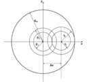
- FIG. 4 is a diagram for explaining an example of a method of calculating an optical path deviation when the ring-shaped illumination light N is incident on the meniscus model M.
- 60a is a culture vessel model
- 31a is an objective lens model
- 32a is a phase plate model
- A is a plane at the position of the phase difference plate model 32a.
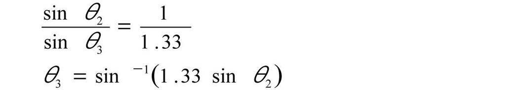
- ⁇ 2 is calculated from Snell's law by the following equation.
- ⁇ 3 is calculated from Snell's law using the following equation.
- the optical path deviation ⁇ x from the optical axis can be calculated by the following equation. Note that f is the focal length of the objective lens model 31a, and the focal position of the objective lens model 31a is focused on the bottom surface of the culture vessel model 60a.
- the range d na of the objective lens model 31a is a ring-shaped illumination light N incident can be calculated by the following equation
- FIG. 5 shows the relationship between the optical path shift ⁇ x in the range d na and plane A Figure It is.
- NA in the following expression is the numerical aperture of the objective lens model 31a.
- ⁇ 1 and ⁇ 2 shown in FIG. 5 indicate the inner diameter and outer diameter of the image of the phase plate model 32a when there is no optical path deviation.
- t 1 and t 2 shown in FIG. 5 indicate the inner diameter and outer diameter of the image of the ring-shaped illumination light N when the optical path deviation is ⁇ x.
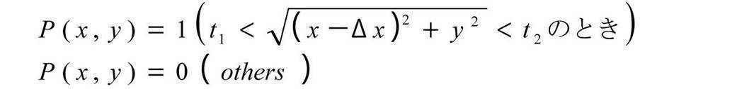
- the transmittance T (x, y) at each position (x, y) in the plane A can be expressed by the following equation.
- incident light intensity P (x, y) at each position (x, y) on the plane A can be expressed by the following equation.
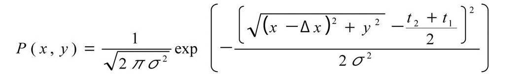
- the incident light intensity P (x, y) may be expressed by a Gaussian distribution, in which case it can be expressed by the following equation.
- the sum O ( ⁇ 1) of the intensity of light passing through the plane A when the liquid surface inclination of the meniscus model M is ⁇ 1 can be expressed by the following equation.
- the liquid surface shape can be estimated with high accuracy by correcting the estimated position using the following equation.
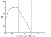
- FIG. 6 is a diagram illustrating an example of the luminance distribution of the phase difference image acquired by the geometric optical simulation.
- the luminance distribution shown in FIG. 6 shows a linear luminance distribution extending from the center of the meniscus model M toward the outer periphery of the culture vessel model 60a, and the horizontal axis of FIG. Distance.
- the center of the meniscus model M is the center position in the center portion of the meniscus described above, and in the case of geometric optical simulation, is the same position as the center position of the culture vessel model 60a.
- the OD value on the vertical axis shown in FIG. 6 is a value obtained by normalizing the luminance value on the straight line with the luminance value at the center of the meniscus model M. As shown in FIG. 6, even in the result of the geometric optical simulation, a bright and dark pattern is formed outward from the central portion of the meniscus.
- the liquid surface shape estimation unit 54 acquires the phase difference image captured by the imaging unit 40 before the adjustment by the adjustment optical system 20 described above, and acquires the luminance distribution of the phase difference image.
- a phase difference image may be captured with the optical characteristics of the adjustment optical system 20 as an initial state, or the adjustment optical system 20 is used as illumination light.
- a phase difference image may be taken in a state of being retracted from the optical path.
- the optical parameters of the adjustment optical system 20 in the initial state are also considered in the geometric optical simulation described above.
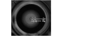
- FIG. 7 is a diagram illustrating an example of a phase difference image captured by the imaging unit 40 before adjustment by the adjustment optical system 20.
- the liquid surface shape estimation unit 54 sets a straight line L extending from the central portion of the meniscus toward the outer periphery of the culture vessel 60 on the phase difference image captured by the imaging unit 40, and the setting is performed.
- the luminance distribution of the phase difference image on the straight line L is acquired.
- stretching direction of the straight line set on the phase difference image when acquiring luminance distribution in geometric optical simulation are the same directions.
- the phase difference image is subjected to smoothing processing such as low-pass filter processing, and the luminance distribution of the phase difference image subjected to the smoothing processing is obtained. You may get it. Thereby, the brightness
- the liquid surface shape estimation unit 54 specifies the center portion of the meniscus based on the luminance of the phase difference image. Specifically, for example, by extracting a region having a luminance equal to or lower than a preset threshold value from the phase difference image, and identifying a circular region near the central portion of the phase difference image among the extracted regions, the center of the meniscus Identify the part. And the straight line L shown in FIG. 7 is set by setting the straight line extended toward the outer side from the center position in the center part of the specified meniscus.
- a correlation function is used to obtain the correlation between these luminance distributions. What should I do?
- inflection points in the luminance distribution of the liquid surface shape stored in advance and the luminance distribution of the phase difference image captured by the imaging unit 40 inflection points in the luminance distribution of the liquid surface shape stored in advance and the luminance distribution of the phase difference image captured by the imaging unit 40.
- the sum of the differences between the luminance values (OD values) of the corresponding inflection points of these luminance distributions may be obtained for each of the plurality of liquid surface shape luminance distributions stored in advance, and the luminance distribution having the smallest total value may be specified as the luminance distribution having the highest correlation.
- the liquid surface shape estimation unit 54 specifies the liquid surface shape with the curvature having the highest correlation with the luminance distribution of the phase difference image captured by the imaging unit 40, and determines the liquid surface shape with the specified curvature as the culture vessel 60. It is estimated as the liquid surface shape of the culture medium C inside.
- the adjustment information acquisition unit 55 acquires adjustment information for adjusting the optical characteristics of the adjustment optical system 20 based on the liquid surface shape estimated by the liquid surface shape estimation unit 54 as described above. Is. Specifically, the adjustment information acquisition unit 55 of the present embodiment acquires the inclination angle of the liquid surface in the imaging region of the phase difference image based on the liquid surface shape estimated by the liquid surface shape estimation unit 54, Based on the inclination angle and the refractive index of the culture medium C, the refraction angle of the illumination light in the imaging region is calculated. In the present embodiment, as described above, the inside of the culture vessel 60 is scanned with illumination light, and phase difference images are taken for each of a plurality of imaging regions obtained by dividing the inside of the culture vessel 60. For, the refraction angle of the illumination light is calculated.
- the adjustment information acquisition unit 55 outputs information on the refraction angle of illumination light in each imaging region to the adjustment optical system control unit 51 as adjustment information.
- the adjustment optical system control unit 51 adjusts the optical characteristics of the adjustment optical system 20 based on the information on the refraction angle of the illumination light calculated by the adjustment information acquisition unit 55. Specifically, the adjustment optical system control unit 51 is preset with a lookup table that associates the refraction angle of the illumination light in the imaging region with the adjustment amount of the adjustment optical element 21 of the adjustment optical system 20. ing. Then, the adjustment optical system control unit 51 acquires the adjustment amount of the adjustment optical element 21 of the adjustment optical system 20 with reference to the lookup table based on the information on the refraction angle of the illumination light, and uses the adjustment amount as the adjustment amount. A corresponding control signal is output to the adjusting optical system driving unit 22. As described above, the adjustment amount of the adjustment optical element 21 of the adjustment optical system 20 includes the position, refractive power, optical axis direction, and the like of the adjustment optical element 21 in the X direction, Y direction, and Z direction.
- the control signal output from the adjustment optical system control unit 51 is input to the adjustment optical system drive unit 22, and the adjustment optical system drive unit 22 uses the refractive power of the adjustment optical element 21 based on the input control signal.
- the optical characteristics are adjusted by adjusting the positions in the X direction, the Y direction, and the Z direction, and the optical axis direction.
- the adjustment information acquisition unit 55 is an optical according to the liquid surface shape estimated by the liquid surface shape estimation unit 54. Information specifying the type of the adjustment optical element 21 having characteristics is acquired as adjustment information. It is assumed that the adjustment information acquisition unit 55 is preset with a table in which the liquid level shape and information for specifying the type of the adjustment optical element 21 corresponding to the liquid level shape are associated with each other.
- adjustment optical system control part 51 the information which specifies the kind of optical element 21 for adjustment acquired in adjustment information acquisition part 55 is outputted to adjustment optical system control part 51, and adjustment optical system control part 51 is based on the inputted information. It automatically switches to the adjusting optical element 21 corresponding to the liquid surface shape. The user may manually replace the adjustment optical element 21 by displaying information specifying the type of the adjustment optical element 21 on the display device 70 to notify the user of the information.
- the imaging optical system control unit 52 moves the objective lens 31 in the Z direction by driving and controlling the imaging optical system driving unit 34. Specifically, the imaging optical system control unit 52 of the present embodiment performs autofocus control by moving the objective lens 31 in the Z direction by the imaging optical system driving unit 34 when capturing a phase difference image. It is.
- the stage control unit 53 controls the stage driving unit 62 to move the stage 61 in the X direction, the Y direction, and the Z direction.
- the stage controller 53 scans the inside of the culture vessel 60 with illumination light by moving the stage 61 in the X direction and the Y direction as described above, and is divided in the culture vessel 60 (for example, in one well). In addition, a phase difference image for each of a plurality of imaging regions is captured.
- the input device 80 includes an input device such as a keyboard and a mouse, and accepts a setting input by a user.
- the display device 70 is configured by a display device such as a liquid crystal display, and displays a phase difference image captured by the imaging unit 40.
- the display device 70 may be configured with a touch panel, and the display device 70 may also serve as an input device.
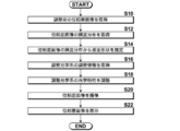
- the culture vessel 60 containing the observation object S and the culture medium C is placed on the stage 61.
- a phase difference image of the observation target S before adjustment by the adjustment optical system 20 is captured and acquired by the liquid surface shape estimation unit 54 (S10).
- the liquid surface shape estimation unit 54 sets a straight line L extending from the central portion of the meniscus toward the outer periphery of the culture vessel 60 on the phase difference image before adjustment as described above, and the phase difference on the set straight line L.
- the luminance distribution of the image is acquired (S12).
- the liquid surface shape luminance distribution having the highest correlation with the luminance distribution of the phase difference image before adjustment is specified, and the specified liquid surface shape is determined as the liquid surface shape of the culture liquid C in the culture vessel 60. (S14).
- the estimation result of the liquid surface shape is output to the adjustment information acquisition unit 55, and the adjustment information acquisition unit 55 acquires adjustment information for adjusting the optical characteristics of the adjustment optical system 20 based on the estimated liquid surface shape. (S16).
- the adjustment information acquired by the adjustment information acquisition unit 55 is output to the adjustment optical system control unit 51.
- the adjustment optical system control unit 51 adjusts the optical characteristics of the adjustment optical system 20 based on the input adjustment information. (S18).
- the optical characteristics of the adjustment optical system 20 are adjusted as described above, and thereby the influence of refraction due to the meniscus formed on the liquid surface of the culture medium C is removed, and then the phase difference image of the observation target S is again displayed. Is imaged by the imaging unit 40 (S20).
- the phase difference image captured by the imaging unit 40 is output to the display device 70 and displayed by the display device 70.
- the liquid surface shape of the culture medium C in the culture vessel 60 is estimated based on the luminance distribution of the phase difference image captured by the imaging unit 40 that captures the phase difference image for observation. Therefore, the liquid surface shape of the culture solution C in the culture vessel 60 can be estimated without providing a new measurement system for estimating the liquid surface shape. Then, based on the estimated liquid surface shape, the optical characteristics of the adjustment optical system 20 are adjusted, and then the phase difference image to be observed is captured, so that the phase difference image in which the influence of the meniscus is suppressed is obtained. An image can be taken.
- one straight line L extending from the central portion of the meniscus toward the outer periphery of the culture vessel 60 is displayed on the phase difference image captured by the imaging unit 40.
- the luminance distribution on the straight line L is used as a representative of the luminance distribution of the entire phase difference image
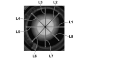
- a plurality of straight lines extending from the central portion of the meniscus toward the outer periphery may be set. . That is, the meniscus formed in the culture vessel 60 is not necessarily formed with the same curvature in each direction from the center toward the outer periphery in the culture vessel 60.
- each straight line L1 to L8 extending from the central portion of the meniscus toward the outer periphery may be set, and the luminance distribution for each straight line may be acquired. Then, by calculating the curvature of the liquid surface shape corresponding to the luminance distribution for each straight line, the curvature of the liquid surface shape may be obtained for each of the eight directions. Thereby, the liquid level shape can be estimated with higher accuracy.
- the curvature R of the liquid surface shape is obtained on the assumption that the liquid surface shape is close to a sphere.
- the meniscus depends on the size of the culture vessel 60. Since the flat bottom surface portion of the liquid becomes large, the liquid surface shape does not become spherical, and there is a possibility that the estimation accuracy of the liquid surface shape is lowered. Therefore, the liquid surface shape may be estimated as follows.
- a profile associating the luminance value P (x) of the phase difference image with the inclination angle ⁇ of the liquid surface as shown in FIG. 11 is acquired.
- the luminance value P (x) represents the luminance value at each position x between the central portion of the meniscus model M and the outer periphery of the culture vessel 60a.
- the liquid surface inclination angle ⁇ is the inclination angle ⁇ 1 shown in FIG. Note that the profile shown in FIG. 11 can be acquired using the calculation result in the above embodiment.
- the phase difference image captured by the imaging unit 40 is acquired, the phase difference image is normalized so that the luminance value of the center portion of the meniscus is 1, and the normalized level is obtained.
- a smoothing process is performed on the phase difference image to remove high-frequency noise derived from cells.
- a straight line extending from the center portion of the meniscus toward the outer periphery is set as shown in FIG. 12, and each position is scanned on the straight line from the center of the meniscus.
- the luminance values at x 1 , x 2 ,..., x n are acquired.
- the inclination angle ⁇ of the liquid level corresponding to the luminance value P (x) at each position x is obtained using the profile shown in FIG.
- the inclination angle ⁇ of the liquid level at each position on the straight line shown in FIG. 12 can be obtained, and the shape of the liquid level on the straight line can be estimated.
- the inclination angle ⁇ of the liquid surface is obtained using the profile shown in FIG. 11, two values are obtained for the same luminance value P (x) (1.5 in the example shown in FIG. 13) as shown in FIG.
- the inclination angle ⁇ may be obtained. Therefore, as described above, when the luminance value is acquired in order from the center of the meniscus and the inclination angle ⁇ corresponding to the luminance value is sequentially obtained, the inclination angle of the liquid surface increases as the distance from the center of the meniscus increases. When there are a plurality of candidates for the inclination angle ⁇ , the smallest inclination angle ⁇ may be selected first.
- the adjustment optical element 21 is provided to remove the influence of the refraction of illumination light caused by the meniscus formed on the liquid surface.
- the optical element 21 may not be provided.
- the slit plate 12 may be moved in the X direction and the Y direction, or the phase plate 32 may be moved in the X direction and the Y direction. You may make it remove the influence of the refraction of the illumination light which originates. That is, the slit plate 12 and the phase plate 32 may be used as the adjustment optical system in the present invention.
- the adjustment optical element 21 is provided between the condenser lens 13 and the culture vessel 60.
- the position of the adjustment optical element 21 is not limited to this position. It may be provided at other positions such as between the light source 11 and the slit plate 12, between the phase plate 32 and the condenser lens 13, and between the culture vessel 60 and the objective lens 31.
Abstract
Description

同様に、スネルの法則から、下式によりθ3が算出される。
そして、光軸からの光路ずれΔxは、下式により算出することができる。なお、fは、対物レンズモデル31aの焦点距離であり、対物レンズモデル31aの焦点位置は、培養容器モデル60aの底面に合焦しているものとする。
また、対物レンズモデル31aにリング状照明光Nが入射する範囲dnaは、下式により算出することができ、図5は、この範囲dnaと平面Aにおける光路ずれΔxとの関係を示す図である。なお、下式におけるNAは対物レンズモデル31aの開口数である。また、図5に示すφ1およびφ2は、光路ずれがない場合における位相板モデル32aの像の内径および外径を示している。また、図5に示すt1およびt2は、光路ずれがΔxの場合におけるリング状照明光Nの像の内径および外径を示している。
そして、位相差板モデル32aの減光率をND(定数)とすると、平面Aにおける(x,y)の位置毎の透過率T(x,y)は、下式で表すことができる。

また、平面Aにおける(x,y)の位置毎の入射光強度P(x,y)は、下式で表すことができる。
なお、このとき、入射光強度P(x,y)をガウス分布で表現してもよく、その場合は、下式で表すことができる。
以上より、メニスカスモデルMの液面の傾斜がθ1のときの平面Aを通過する光の強度の総和O(θ1)は、下式で表すことができる。
上述したような演算に基づく幾何光学シミュレーションを行うことによって、メニスカスモデルMの液面上の各位置を通過した光の強度の分布、すなわち位相差画像の輝度分布を取得することができる。
そして、互いに異なる曲率を有する複数の液面形状のそれぞれの位相差画像の輝度分布が取得され、液面形状推定部54にこれらの輝度分布が予め記憶される。図6は、幾何光学シミュレーションによって取得された位相差画像の輝度分布の一例を示す図である。図6に示す輝度分布は、メニスカスモデルMの中心から培養容器モデル60aの外周に向かって延びる直線上の輝度分布を示したものであり、図6の横軸は、メニスカスモデルMの中心からの距離である。なお、メニスカスモデルMの中心とは、上述したメニスカスの中心部分の中の中央位置のことであり、幾何光学シミュレーションの場合には、培養容器モデル60aの中心位置と同じ位置となる。また、図6に示す縦軸のOD値は、上述した直線上の輝度値を、メニスカスモデルMの中心の輝度値によって規格化した値である。図6に示すように、幾何光学シミュレーションによる結果においても、メニスカスの中央部分から外側に向かって明暗パターンが形成される。
11 白色光源
12 スリット板
12a スリット板モデル
13 コンデンサレンズ
13a コンデンサレンズモデル
20 調整光学系
21 調整用光学素子
22 調整光学系駆動部
30 結像光学系
31 対物レンズ
31a 対物レンズモデル
32 位相板
32a 位相板モデル
33 結像レンズ
34 結像光学系駆動部
40 撮像部
50 顕微鏡制御装置
51 調整光学系制御部
52 結像光学系制御部
53 ステージ制御部
54 液面形状推定部
55 調整情報取得部
60 培養容器
60a 培養容器モデル
61 ステージ
62 ステージ駆動部
70 表示装置
80 入力装置
C 培養液
Ca 培養液モデル
G1 輝度分布
G2 輝度分布
L 直線
L1-L8 直線
M メニスカスモデル
N リング状照明光
P 観察対象設置面
Claims (11)
- 液体および観察対象が収容された容器に対して位相差計測用の照明光を照射する照明光照射部と、
前記照明光を照射した前記観察対象を撮像する撮像部と、
前記容器内の液体の液面形状に起因する前記照明光の屈折を調整する調整光学系と、
前記撮像部によって撮像された前記観察対象の位相差画像の輝度分布に基づいて、前記容器内の液体の液面形状を推定する液面形状推定部と、
前記液面形状推定部によって推定された液面形状に基づいて、前記調整光学系の光学特性を調整するための調整情報を取得する調整情報取得部とを備えたことを特徴とする位相差顕微鏡。 - 前記調整情報取得部によって取得された調整情報に基づいて、前記調整光学系の光学特性を調整する調整光学系制御部を備えた請求項1記載の位相差顕微鏡。
- 前記液面形状推定部が、予め設定された液面形状を用いて幾何光学シミュレーションを行って取得された位相差画像の輝度分布に基づいて、前記容器内の液体の液面形状を推定する請求項1または2記載の位相差顕微鏡。
- 前記液面形状推定部が、互いに異なる曲率を有する、予め設定された複数の液面形状を用いてそれぞれ幾何光学シミュレーションを行って取得された複数の位相差画像の輝度分布に基づいて、前記容器内の液体の液面形状を推定する請求項3記載の位相差顕微鏡。
- 前記液面形状推定部が、前記幾何光学シミュレーションを用いて取得された位相差画像の輝度分布と前記撮像部によって撮像された位相差画像の輝度分布との相関関係を求めることによって、前記容器内の液体の液面形状を推定する請求項3または4記載の位相差顕微鏡。
- 前記液面形状推定部が、相関関数を用いて前記相関関係を求める請求項5記載の位相差顕微鏡。
- 前記液面形状推定部が、前記幾何光学シミュレーションを用いて取得された位相差画像の輝度分布における変曲点の輝度値と前記撮像部によって撮像された位相差画像の輝度分布における変曲点の輝度値とに基づいて、前記相関関係を求める請求項5記載の位相差顕微鏡。
- 前記液面形状推定部が、前記撮像部によって撮像された位相差画像上において、前記容器内に形成されるメニスカスの中心部分から前記容器の外周に向かって延びる少なくとも一つの直線を設定し、該設定した直線上の前記位相差画像の輝度分布に基づいて、前記容器内の液体の液面形状を推定する請求項1から7いずれか1項記載の位相差顕微鏡。
- 前記液面形状推定部が、互いに異なる複数の方向に延びる前記直線を設定し、該複数の直線上の位相差画像の輝度分布に基づいて、前記容器内の液体の液面形状を推定する請求項8記載の位相差顕微鏡。
- 前記液面形状推定部が、前記撮像部によって撮像された位相差画像に対して平滑化処理を施し、該平滑化処理の施された位相差画像の輝度分布に基づいて、前記容器内の液体の液面形状を推定する請求項1から9いずれか1項記載の位相差顕微鏡。
- 液体および観察対象が収容された容器に対して位相差計測用の照明光を照射して、前記観察対象の位相差画像を撮像し、
該撮像した位相差画像の輝度分布に基づいて、前記液体の液面形状を推定し、
前記推定した液面形状に基づいて、前記容器内の液体の液面形状に起因する光の屈折を調整する調整光学系の光学特性を調整するための調整情報を取得し、
該調整情報に基づいて、前記調整光学系の光学特性が調整された後、前記容器に対して前記照明光を照射し、
前記照明光を照射した前記観察対象を撮像することを特徴とする撮像方法。
Priority Applications (3)
| Application Number | Priority Date | Filing Date | Title |
|---|---|---|---|
| KR1020187022710A KR102054095B1 (ko) | 2016-02-22 | 2017-02-13 | 위상차 현미경 및 촬상 방법 |
| EP17756280.8A EP3422073B1 (en) | 2016-02-22 | 2017-02-13 | Phase-contrast microscope and imaging method |
| US16/053,509 US10831009B2 (en) | 2016-02-22 | 2018-08-02 | Phase contrast microscope and imaging method |
Applications Claiming Priority (2)
| Application Number | Priority Date | Filing Date | Title |
|---|---|---|---|
| JP2016-030705 | 2016-02-22 | ||
| JP2016030705A JP6594223B2 (ja) | 2016-02-22 | 2016-02-22 | 位相差顕微鏡および撮像方法 |
Related Child Applications (1)
| Application Number | Title | Priority Date | Filing Date |
|---|---|---|---|
| US16/053,509 Continuation US10831009B2 (en) | 2016-02-22 | 2018-08-02 | Phase contrast microscope and imaging method |
Publications (1)
| Publication Number | Publication Date |
|---|---|
| WO2017145839A1 true WO2017145839A1 (ja) | 2017-08-31 |
Family
ID=59685125
Family Applications (1)
| Application Number | Title | Priority Date | Filing Date |
|---|---|---|---|
| PCT/JP2017/005128 WO2017145839A1 (ja) | 2016-02-22 | 2017-02-13 | 位相差顕微鏡および撮像方法 |
Country Status (5)
| Country | Link |
|---|---|
| US (1) | US10831009B2 (ja) |
| EP (1) | EP3422073B1 (ja) |
| JP (1) | JP6594223B2 (ja) |
| KR (1) | KR102054095B1 (ja) |
| WO (1) | WO2017145839A1 (ja) |
Cited By (2)
| Publication number | Priority date | Publication date | Assignee | Title |
|---|---|---|---|---|
| WO2019039035A1 (ja) * | 2017-08-25 | 2019-02-28 | 富士フイルム株式会社 | 判別器の学習装置、方法およびプログラム、並びに判別器 |
| CN113532800A (zh) * | 2021-05-21 | 2021-10-22 | 杭州涂鸦信息技术有限公司 | 透光区域的分析方法以及相关设备、装置 |
Families Citing this family (2)
| Publication number | Priority date | Publication date | Assignee | Title |
|---|---|---|---|---|
| JP6411294B2 (ja) * | 2015-06-30 | 2018-10-24 | 富士フイルム株式会社 | 位相差顕微鏡および撮像方法 |
| KR20220102324A (ko) * | 2021-01-12 | 2022-07-20 | 정홍준 | 투명 디스플레이 패널을 이용한 현미경의 투과광 형성장치 |
Citations (4)
| Publication number | Priority date | Publication date | Assignee | Title |
|---|---|---|---|---|
| US20100047845A1 (en) * | 2007-02-26 | 2010-02-25 | Stemcell Technologies Inc. | Method of reducing curvature in a meniscus of liquid medium |
| JP2012013888A (ja) * | 2010-06-30 | 2012-01-19 | Nikon Corp | 顕微鏡、培養観察装置 |
| JP2012073591A (ja) * | 2010-09-03 | 2012-04-12 | Olympus Corp | 位相物体の可視化方法及び可視化装置 |
| JP2015152650A (ja) | 2014-02-12 | 2015-08-24 | 株式会社ニコン | 位相差顕微鏡 |
Family Cites Families (6)
| Publication number | Priority date | Publication date | Assignee | Title |
|---|---|---|---|---|
| JP5008763B2 (ja) * | 2010-12-03 | 2012-08-22 | キヤノン株式会社 | 屈折率分布計測方法、屈折率分布計測装置および光学素子の製造方法 |
| US9069175B2 (en) * | 2011-04-08 | 2015-06-30 | Kairos Instruments, Llc | Adaptive phase contrast microscope |
| JP5946751B2 (ja) * | 2012-11-08 | 2016-07-06 | 株式会社日立ハイテクノロジーズ | 欠陥検出方法及びその装置並びに欠陥観察方法及びその装置 |
| JP2015152649A (ja) * | 2014-02-12 | 2015-08-24 | 株式会社ニコン | 位相差顕微鏡 |
| JP6380983B2 (ja) * | 2014-11-26 | 2018-08-29 | 富士フイルム株式会社 | 位相差顕微鏡 |
| JP6513507B2 (ja) * | 2015-06-30 | 2019-05-15 | 富士フイルム株式会社 | 位相差顕微鏡および撮像方法 |
-
2016
- 2016-02-22 JP JP2016030705A patent/JP6594223B2/ja active Active
-
2017
- 2017-02-13 EP EP17756280.8A patent/EP3422073B1/en active Active
- 2017-02-13 KR KR1020187022710A patent/KR102054095B1/ko active IP Right Grant
- 2017-02-13 WO PCT/JP2017/005128 patent/WO2017145839A1/ja active Application Filing
-
2018
- 2018-08-02 US US16/053,509 patent/US10831009B2/en active Active
Patent Citations (4)
| Publication number | Priority date | Publication date | Assignee | Title |
|---|---|---|---|---|
| US20100047845A1 (en) * | 2007-02-26 | 2010-02-25 | Stemcell Technologies Inc. | Method of reducing curvature in a meniscus of liquid medium |
| JP2012013888A (ja) * | 2010-06-30 | 2012-01-19 | Nikon Corp | 顕微鏡、培養観察装置 |
| JP2012073591A (ja) * | 2010-09-03 | 2012-04-12 | Olympus Corp | 位相物体の可視化方法及び可視化装置 |
| JP2015152650A (ja) | 2014-02-12 | 2015-08-24 | 株式会社ニコン | 位相差顕微鏡 |
Non-Patent Citations (1)
| Title |
|---|
| See also references of EP3422073A4 |
Cited By (3)
| Publication number | Priority date | Publication date | Assignee | Title |
|---|---|---|---|---|
| WO2019039035A1 (ja) * | 2017-08-25 | 2019-02-28 | 富士フイルム株式会社 | 判別器の学習装置、方法およびプログラム、並びに判別器 |
| US11328522B2 (en) | 2017-08-25 | 2022-05-10 | Fujifilm Corporation | Learning device, method, and program for discriminator, and discriminator |
| CN113532800A (zh) * | 2021-05-21 | 2021-10-22 | 杭州涂鸦信息技术有限公司 | 透光区域的分析方法以及相关设备、装置 |
Also Published As
| Publication number | Publication date |
|---|---|
| JP6594223B2 (ja) | 2019-10-23 |
| KR102054095B1 (ko) | 2019-12-09 |
| EP3422073A4 (en) | 2019-03-06 |
| EP3422073B1 (en) | 2020-04-22 |
| US20190033569A1 (en) | 2019-01-31 |
| JP2017151132A (ja) | 2017-08-31 |
| EP3422073A1 (en) | 2019-01-02 |
| KR20180102118A (ko) | 2018-09-14 |
| US10831009B2 (en) | 2020-11-10 |
Similar Documents
| Publication | Publication Date | Title |
|---|---|---|
| JP6380983B2 (ja) | 位相差顕微鏡 | |
| EP3318912B1 (en) | Phase contrast microscope and imaging method | |
| WO2017145839A1 (ja) | 位相差顕微鏡および撮像方法 | |
| JP6461128B2 (ja) | 細胞評価装置および方法並びにプログラム | |
| JP6513507B2 (ja) | 位相差顕微鏡および撮像方法 | |
| JP6301199B2 (ja) | 細胞評価装置および方法並びにプログラム | |
| JP6173950B2 (ja) | 細胞撮像制御装置および方法並びにプログラム | |
| JP5177138B2 (ja) | 観察装置 | |
| KR102073503B1 (ko) | 현미경 및 관찰 방법 | |
| US11061214B2 (en) | Cell observation apparatus and method | |
| EP3835721A1 (en) | A method for measuring a height map of a test surface | |
| WO2019069823A1 (ja) | 撮像装置、撮像装置の作動方法及び撮像制御プログラム |
Legal Events
| Date | Code | Title | Description |
|---|---|---|---|
| ENP | Entry into the national phase |
Ref document number: 20187022710 Country of ref document: KR Kind code of ref document: A |
|
| WWE | Wipo information: entry into national phase |
Ref document number: 1020187022710 Country of ref document: KR |
|
| NENP | Non-entry into the national phase |
Ref country code: DE |
|
| WWE | Wipo information: entry into national phase |
Ref document number: 2017756280 Country of ref document: EP |
|
| ENP | Entry into the national phase |
Ref document number: 2017756280 Country of ref document: EP Effective date: 20180924 |
|
| 121 | Ep: the epo has been informed by wipo that ep was designated in this application |
Ref document number: 17756280 Country of ref document: EP Kind code of ref document: A1 |