EP3420142B1 - Vorrichtung zur verdichtung eines untergrundes - Google Patents
Vorrichtung zur verdichtung eines untergrundes Download PDFInfo
- Publication number
- EP3420142B1 EP3420142B1 EP17703698.5A EP17703698A EP3420142B1 EP 3420142 B1 EP3420142 B1 EP 3420142B1 EP 17703698 A EP17703698 A EP 17703698A EP 3420142 B1 EP3420142 B1 EP 3420142B1
- Authority
- EP
- European Patent Office
- Prior art keywords
- contact plate
- baseplate
- base plate
- plate
- connection
- Prior art date
- Legal status (The legal status is an assumption and is not a legal conclusion. Google has not performed a legal analysis and makes no representation as to the accuracy of the status listed.)
- Active
Links
Images


Classifications
-
- E—FIXED CONSTRUCTIONS
- E01—CONSTRUCTION OF ROADS, RAILWAYS, OR BRIDGES
- E01C—CONSTRUCTION OF, OR SURFACES FOR, ROADS, SPORTS GROUNDS, OR THE LIKE; MACHINES OR AUXILIARY TOOLS FOR CONSTRUCTION OR REPAIR
- E01C19/00—Machines, tools or auxiliary devices for preparing or distributing paving materials, for working the placed materials, or for forming, consolidating, or finishing the paving
- E01C19/22—Machines, tools or auxiliary devices for preparing or distributing paving materials, for working the placed materials, or for forming, consolidating, or finishing the paving for consolidating or finishing laid-down unset materials
- E01C19/30—Tamping or vibrating apparatus other than rollers ; Devices for ramming individual paving elements
- E01C19/34—Power-driven rammers or tampers, e.g. air-hammer impacted shoes for ramming stone-sett paving; Hand-actuated ramming or tamping machines, e.g. tampers with manually hoisted dropping weight
- E01C19/38—Power-driven rammers or tampers, e.g. air-hammer impacted shoes for ramming stone-sett paving; Hand-actuated ramming or tamping machines, e.g. tampers with manually hoisted dropping weight with means specifically for generating vibrations, e.g. vibrating plate compactors, immersion vibrators
-
- E—FIXED CONSTRUCTIONS
- E01—CONSTRUCTION OF ROADS, RAILWAYS, OR BRIDGES
- E01C—CONSTRUCTION OF, OR SURFACES FOR, ROADS, SPORTS GROUNDS, OR THE LIKE; MACHINES OR AUXILIARY TOOLS FOR CONSTRUCTION OR REPAIR
- E01C19/00—Machines, tools or auxiliary devices for preparing or distributing paving materials, for working the placed materials, or for forming, consolidating, or finishing the paving
- E01C19/22—Machines, tools or auxiliary devices for preparing or distributing paving materials, for working the placed materials, or for forming, consolidating, or finishing the paving for consolidating or finishing laid-down unset materials
- E01C19/30—Tamping or vibrating apparatus other than rollers ; Devices for ramming individual paving elements
- E01C19/34—Power-driven rammers or tampers, e.g. air-hammer impacted shoes for ramming stone-sett paving; Hand-actuated ramming or tamping machines, e.g. tampers with manually hoisted dropping weight
-
- E—FIXED CONSTRUCTIONS
- E02—HYDRAULIC ENGINEERING; FOUNDATIONS; SOIL SHIFTING
- E02D—FOUNDATIONS; EXCAVATIONS; EMBANKMENTS; UNDERGROUND OR UNDERWATER STRUCTURES
- E02D3/00—Improving or preserving soil or rock, e.g. preserving permafrost soil
- E02D3/02—Improving by compacting
- E02D3/046—Improving by compacting by tamping or vibrating, e.g. with auxiliary watering of the soil
- E02D3/068—Vibrating apparatus operating with systems involving reciprocating masses
-
- E—FIXED CONSTRUCTIONS
- E02—HYDRAULIC ENGINEERING; FOUNDATIONS; SOIL SHIFTING
- E02D—FOUNDATIONS; EXCAVATIONS; EMBANKMENTS; UNDERGROUND OR UNDERWATER STRUCTURES
- E02D3/00—Improving or preserving soil or rock, e.g. preserving permafrost soil
- E02D3/02—Improving by compacting
- E02D3/046—Improving by compacting by tamping or vibrating, e.g. with auxiliary watering of the soil
- E02D3/074—Vibrating apparatus operating with systems involving rotary unbalanced masses
-
- E—FIXED CONSTRUCTIONS
- E02—HYDRAULIC ENGINEERING; FOUNDATIONS; SOIL SHIFTING
- E02F—DREDGING; SOIL-SHIFTING
- E02F3/00—Dredgers; Soil-shifting machines
- E02F3/04—Dredgers; Soil-shifting machines mechanically-driven
- E02F3/96—Dredgers; Soil-shifting machines mechanically-driven with arrangements for alternate or simultaneous use of different digging elements
- E02F3/967—Dredgers; Soil-shifting machines mechanically-driven with arrangements for alternate or simultaneous use of different digging elements of compacting-type tools
Definitions
- a device described above can be, for example, a so-called vibrating plate, which is either remotely controlled or moved manually over the subsoil to be compacted. If such a device is moved by hand, it typically has a drawbar by means of which a person guiding the device can steer the device.
- the “base plate” of such a device refers to the component by means of which the device typically comes into contact with the subsoil to be compacted.
- the base plate is consequently the component that transfers the forces generated by the device to the subsoil to be compacted.
- the base plate is formed from a steel part several millimeters thick.
- a contact plate is additionally arranged below the base plate, that is to say on a side facing the subsurface, and instead of the base plate, it comes into contact with the subsoil to be compacted during operation of the device.
- a contact plate can be formed, for example, from a plastic material, such a contact plate serving in particular to dampen forces acting on the substrate and thus, for example, to avoid damage to the same. It is also conceivable that a contact plate is made of steel and takes on the function of a wear protection plate that protects the base plate of the device from the direct action of forces.
- a thickness of both the base plate and the contact plate is generally not more than 30 mm, while both a length and a width of the respective plate are typically several 100 mm.
- a “non-destructive detachable" connection between the contact plate and the base plate is understood to mean a connection which can be closed and released again as often as desired without damage to one of the two plates.
- the contact plate is connected to the base plate by means of a connecting means, for example a screw bolt. It is understood that such a connection can be restored at will can be solved, both the base plate and the contact plate are not damaged.
- the "force-transmitting connection" between the base plate and the contact plate is not necessarily to be understood as being direction-independent. In order to be able to use the device together with its contact plate sensibly, it is generally only necessary that a relative movement between the plates in a forward direction of the device is prevented by means of the force-transmitting connection between the base plate and the contact plate. This means that in the course of the forward movement of the device, which represents its primary working direction, the contact plate should not become detached from the base plate, so that in particular it is prevented that the device together with its base plate moves forward while the contact plate remains in place .
- contact plates can be wear protection plates as well as insulation plates.
- the devices shown in these documents have in common that the contact plates provided there are arranged on the associated base plates by means of the need to use tools. It is shown, on the one hand, to attach a respective contact plate to the base plate itself and, on the other hand, to anchor the contact plate to the upper carriage of the device by means of a connecting device.
- the present application is therefore based on the object of simplifying the assembly and disassembly of a contact plate on a device for compacting a subsurface compared to the prior art.
- connection area is formed on the rest of the contact plate in such a way that - in an installed state of the contact plate - starting from the underside of the base plate to one facing the superstructure Extends top of the base plate and engages there with the top.
- connection area is designed in such a way that it engages around the base plate in a form-fitting manner at least in a corresponding form-fit area. This engagement between the contact plate and the base plate takes place in such a way that a force-transmitting connection between the contact plate and the base plate is established or can be produced solely on the basis of the form-fitting connection between the contact plate and the base plate.
- a “directly form-fitting connection” is understood to mean a connection which forms a form-fit connection, the partners of the form-fitting connection being the contact plate and the base plate.
- Specifying this form-fitting connection as "direct” means that no separate connecting means are used to produce the form-fitting connection, for example bolt-shaped connecting means that penetrate both the base plate and the contact plate and thereby establish a form-fitting engagement between the two components.
- a form-fitting connection of the last-mentioned type describes in the context of the present application only an "indirect" form-fitting connection.
- Such indirect positive connections are already known in the prior art and are not suitable for realizing the advantages achieved here by the subject matter of the invention, which are described below.
- the contact plate has a plurality of connection areas which encompass the base plate in a form-fitting manner at different points, that is to say in different form-fit areas.
- the contact plate can each have a connection area of the type described at its two front corners.
- connection area of the contact plate encompasses the base plate in a corner area, so that at least part of the connection area of the contact plate surrounds the forwardly directed outer edge of the base plate and at least another part of the connection area surrounds a lateral edge of the base plate.
- the contact plate advantageously has such a connection area at least in its two front corner areas, viewed in the forward direction of the device. A corresponding design can be found in the exemplary embodiment below.
- the power transmission due to the direct form fit is designed at least in such a way that the device can execute a forward movement during operation without the contact plate and the base plate becoming detached from one another.
- a relative movement of the two components is blocked at least parallel to the forward direction of the device.
- the direct form fit formed between the components also enables a sideways movement or a backward movement of the device without the contact plate and the base plate moving relative to one another. This will be discussed separately below.
- Such a pronounced form fit between the components is not absolutely necessary for the primary success according to the invention, since the device generally executes a forward movement in an operating state.
- the device according to the invention has many advantages.
- the workflow on the construction site is significantly improved compared to the prior art.
- the device which can in particular be formed by a vibrating plate, onto the contact plate in its operating state, in particular from a rear end of the contact plate in the direction of a front end thereof.
- the contact plate For the connection of the contact plate to the base plate of the device, it is consequently only necessary in this procedure to place the contact plate on the ground and to drive the device onto the contact plate, which is done solely by means of the drive device of the device and possibly with the help of the muscle power of those operating the device Person can be done.
- the contact plate and the base plate finally engage with one another in a force-transmitting manner by means of the form fit. After this state has been reached, the device can be used together with the contact plate without additional measures having to be taken.
- a thickness of the contact plate on said edge side should not be more than 7 cm, preferably not more than 5 cm, more preferably not more than 4 cm.
- connection between the contact plate and the base plate is completely free of additional connecting means.
- additional connecting means At least for the execution of a forward movement of the device, this applies in principle in the sense of the invention.
- an additional connecting means is also not required for such movements of the device.
- the direct form fit between the base plate and the contact plate is advantageously designed in such a way that the device can be used in several directions of movement completely independently of additional movement means.
- such a device is of particular advantage in which the contact plate and the base plate can be connected to one another without tools and can also be detached from one another without tools.
- it is possible at any time on the construction site to connect the contact plate and the base plate to one another or to detach them from one another. There is no need to purchase a tool. This further simplifies the operation of the device according to the invention.
- the contact plate is made in one piece. This applies in particular to those cases in which the contact plate is made of a plastic.
- contact plates are used that are comparatively soft so that they have a damping effect.
- Contact plates made from Vulkollan® are used here in particular. This is a polyester-urethane rubber that has a rubber-like consistency and is particularly durable against mechanical loads. Other comparable plastics can of course also be used be beneficial.
- the design of a one-piece contact plate is particularly simple when it is manufactured from a plastic, since such a material can easily be brought into any shape and can thus be adapted, for example, to a wide variety of base plate geometries.
- the device according to the invention is further advantageous when the contact plate has at least one outer collar extending perpendicular to its base surface, which when the contact plate is installed forms a lateral stop surface for a corresponding outer edge of the base plate.
- This collar of the contact plate is advantageously designed at least along the longitudinal sides of the contact plate, further preferably circumferentially, so that to a certain extent the entire circumferential outer edge of the base plate is laterally enclosed by means of the outer collar of the contact plate.
- the collar of the contact plate is designed in such a way that it blocks a movement of the base plate relative to the contact plate in the direction of the collar of the contact plate.
- the contact plate is formed from a material whose rigidity is well below the rigidity of the base plate.
- the stiffness of the contact plate is at most 25%, preferably at most 5%, more preferably at most 0.5%, of the stiffness of the base plate.
- the stiffness ratio is 200,000 N / mm 2 to 100 N / mm 2 .
- the stiffness of the contact plate in this case is consequently only 0.05% of the stiffness of the base plate.
- the device according to the invention can then be particularly advantageous if it has at least one locking element by means of which the contact plate can be locked on the base plate.
- This locking element can be formed on the undercarriage of the device, in particular on the base plate, or on the contact plate.
- the locking element is advantageously formed on the contact plate. If this is the case, it is also advantageous if the locking element is formed in one piece with the contact plate.
- the locking element can be a type of clip, for example, which is deflected by applying a force, for example by stepping on a transmission surface with a foot, the locking element being resilient deformed.
- the locking element can be arranged on the base plate in such a way that it forms a positive fit with the base plate after the force has been released and the resulting elastic recovery, in particular encompasses the base plate with a positive fit.
- the arrangement of a locking element on the device, in particular on the contact plate, is particularly advantageous in those cases in which a relative movement between the contact plate and the base plate is blocked in all directions of the device by means of a direct form fit.
- the locking element it is then possible to release such a form fit at least in one direction of movement of the device and then to move the device in precisely this direction, so that a relative movement occurs between the contact plate and the rest of the device.
- the rest of the device can be "moved down" from the contact plate in a particularly simple manner.
- connection area is molded onto the rest of the contact plate, and - in an installed state of the contact plate - starting from the underside of the base plate, the base plate positively engages around to form a the upper carriage facing the upper side of the base plate extends and engages there with the upper side
- retraction is understood to mean a translational relative movement between the contact plate and the base plate.
- this retraction is designed in such a way that the contact plate is placed on a surface and then the base plate or the rest of the device as a whole is moved onto the contact plate using the normal driving operation of the device until the base plate has finally moved into the connection area of the contact plate, so that the indirect form fit is present.
- the device can advantageously be moved starting from a rear end of the contact plate in the direction of its front end, the base plate moving into a connection area of the contact plate in the course of this movement.
- the method according to the invention has many advantages.
- it enables the contact plate to be connected to the base plate without the use of tools.
- the advantages of such a procedure have already been explained above. It goes without saying that the method according to the invention can be carried out particularly easily by means of the device according to the invention described above.
- the contact plate To carry out method steps d) and e), it is necessary for the contact plate to be formed from a material that can be elastically deformed by the action of a force that can be applied by a person without technical aids.
- the use of plastic comes into consideration here, in particular the use of a polyester-urethane rubber.
- the second method mentioned here also has the advantages mentioned above in connection with the first mentioned method. In particular, it can be carried out on the construction site without the use of tools or other aids.
- the force-transmitting connection between the base plate and the contact plate is always achieved by means of the direct form fit between the two components.
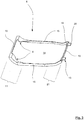
- the embodiment shown in Figures 1 to 3 comprises a device 1 for compacting a subsoil.
- the device 1 is formed here by a hand-held vibrating plate.
- the device 1 comprises an upper carriage 4 and an undercarriage 2, the upper carriage 4 and the undercarriage 2 being connected to one another in a force-transmitting manner.
- a vibration exciter is arranged on the upper carriage 4 , which is suitable for causing the upper carriage 4 - and due to the force-transmitting connection also the undercarriage 2 - to vibrate.
- the particular subsoil to be compacted can be compacted by means of the device 1 .
- the superstructure 4 interacts with a drawbar 5 which is arranged on the superstructure 4 with the interposition of buffer elements.
- the device 1 can overall be controlled by a person guiding the device 1 by means of the drawbar 5. In particular, a direction of movement of the device 1 can be influenced by means of the drawbar 5.
- a base plate 3 which is suitable for coming into direct contact with the respective subsoil to be compacted.
- the base plate 3 is typically formed from a particularly wear-resistant material, in particular steel. It goes without saying that the base plate 3 is exposed to considerable labor forces during operation of the device 1 according to the invention, which lead to severe wear on the base plate 3 . Due to its particularly high rigidity, the subsoil to be compacted is also exposed to a considerable amount of force. In typical applications in which the device 1 is used to compact loose soil, for example sandy soil, the effect of the force on the soil, in particular the frictional force exerted by means of the base plate, is of no further relevance.
- the base plate 3 is therefore equipped in the example shown with a contact plate 6 , which here acts as a damping plate.
- the contact plate 6 is formed here from a polyester urethane rubber. Due to its particularly low stiffness compared to the material of the base plate 3 , it is suitable for distributing the forces acting on the substrate to be compacted by means of the base plate 3 and thus avoiding punctual loading of the substrate and in particular its surface.
- the base plate 3 and the contact plate 6 are connected to one another in a force-transmitting manner.
- the contact plate 6 has two front connection areas 8 which are arranged in a front end section 11 of the contact plate 6 .
- the connection areas 8 are suitable for interlocking with corresponding form-fit areas 10 of the base plate 3. In the example shown, this is accomplished in such a way that the connection areas 8 encompass the base plate 3 in the front corner areas of the base plate 3.
- the material of the contact plate 6 in the connection areas 8 is guided over a front edge 12 of the base plate 3 to an upper side 9 of the base plate 3. There the material extends above the top side 9 of the base plate 3 and thus encloses the base plate 3 in a form-fitting manner in its form-fit areas 10.
- the contact plate 6 is designed in its connection areas 8 , so to speak, in the form of a negative of the base plate 3 , so that the base plate 3 with its form-fit areas 10 engages "precisely" in the connection areas 8 of the contact plate 6.
- the resulting form- fit connection between the contact plate 6 and the base plate 3 represents a direct form fit within the meaning of the present application.
- This form fit between the connection areas 8 of the contact plate 6 and the form-fit areas 10 of the base plate 3 ensures that the base plate 3 moves in the forward direction 17 of the device 1 according to the invention cannot be moved relative to the contact plate 6. In other words, in the course of a forward movement of the device 1, the contact plate 6 is "dragged along" due to the forward movement of the base plate 3.
- the contact plate 6 is also equipped with a circumferential collar 15 which extends perpendicular to a base surface 14 of the contact plate 6 .
- the collar 15 is formed along an outer edge of the contact plate 6 so that it is suitable for interlocking with a corresponding outer edge 16 of the base plate 3. This interaction of the contact plate 6 with the base plate 3 results in particular from the illustration according to FIG Figure 2 .
- the circumferential collar 15 of the contact plate 6 ensures that, in addition to blocking a relative movement between the base plate 3 and the contact plate 6 in the forward direction 17 of the device 1, relative movements in the rearward direction 18 and in the lateral directions 7 are also blocked. In this way it is possible to move the device 1 according to the invention in any direction without the contact plate 6 being inadvertently detached from the base plate 3 .
- the same has a total of two locking elements 13. These are suitable for producing a reversible form fit between the contact plate 6 and the base plate 3.
- the locking elements 13 are each equipped with a form-fit section 19 which extends in the direction of a center of the contact plate 6 and is suitable for engaging with the top side 9 of the base plate 3 in a form-fitting manner.
- these form-fit sections 19 are made significantly smaller, so that it is possible to move a respective form-fit section 19 by deflecting the respective entire locking element 13 in such a way that it is no longer in a form-fitting manner with the base plate 3 Intervention is located.
- the locking elements 13 have a transmission section 20 which extends away from the contact plate 6 and which, for example, can be deflected particularly easily by stepping on with the foot.
- the direct form-fitting connection between the contact plate 6 and the base plate 3 can be very easily achieved in this manner, is moved relative to detachment of the locking elements of the base plate 3, the rest of the device 1 in the reverse direction 18 to the contact plate 6 can be separated again until the contact plate 6 and the rest of the device 1 exist from each other.
- the material of the contact plate 6 is made elastic in such a way that it can deform under the mass of the rest of the device 1 , so that despite the upwardly curved configuration of the contact plate 6 in its rear end section 21, the device 1 over the contact plate 6 can drive without destroying them.
- the contact plate 6 has, at least in sections along its outer edge, preferably circumferentially, one or more connection areas which are designed in such a way that they can be expanded by means of an elastic deformation and on in this way - roughly comparable to the locking elements 13 described - can be slipped over the base plate 3.
- the contact plate 6 and the base plate 3 are connected to one another by forming a direct form fit in a force-transmitting manner in such a way that the base plate 3 moves relative to the contact plate 6 at least in the forward direction 17 , preferably further in the backward direction 18, further preferably in all directions of movement, of the device 1 is blocked.
Landscapes
- Engineering & Computer Science (AREA)
- Structural Engineering (AREA)
- Life Sciences & Earth Sciences (AREA)
- Civil Engineering (AREA)
- General Life Sciences & Earth Sciences (AREA)
- Agronomy & Crop Science (AREA)
- Environmental & Geological Engineering (AREA)
- Soil Sciences (AREA)
- Mining & Mineral Resources (AREA)
- Paleontology (AREA)
- General Engineering & Computer Science (AREA)
- Architecture (AREA)
- Connection Of Plates (AREA)
- Road Paving Structures (AREA)
- Investigation Of Foundation Soil And Reinforcement Of Foundation Soil By Compacting Or Drainage (AREA)
- Road Paving Machines (AREA)
- Vibration Prevention Devices (AREA)
Priority Applications (1)
| Application Number | Priority Date | Filing Date | Title |
|---|---|---|---|
| PL17703698T PL3420142T3 (pl) | 2016-02-22 | 2017-02-01 | Urządzenie do zagęszczania podłoża |
Applications Claiming Priority (2)
| Application Number | Priority Date | Filing Date | Title |
|---|---|---|---|
| DE102016103024.4A DE102016103024A1 (de) | 2016-02-22 | 2016-02-22 | Vorrichtung zur Verdichtung eines Untergrundes |
| PCT/EP2017/052093 WO2017144245A1 (de) | 2016-02-22 | 2017-02-01 | Vorrichtung zur verdichtung eines untergrundes |
Publications (2)
| Publication Number | Publication Date |
|---|---|
| EP3420142A1 EP3420142A1 (de) | 2019-01-02 |
| EP3420142B1 true EP3420142B1 (de) | 2021-06-30 |
Family
ID=57984915
Family Applications (1)
| Application Number | Title | Priority Date | Filing Date |
|---|---|---|---|
| EP17703698.5A Active EP3420142B1 (de) | 2016-02-22 | 2017-02-01 | Vorrichtung zur verdichtung eines untergrundes |
Country Status (11)
| Country | Link |
|---|---|
| US (1) | US10494775B2 (pl) |
| EP (1) | EP3420142B1 (pl) |
| JP (1) | JP2019507266A (pl) |
| CN (1) | CN108699793B (pl) |
| AU (1) | AU2017223898B2 (pl) |
| CA (1) | CA3014279A1 (pl) |
| DE (1) | DE102016103024A1 (pl) |
| ES (1) | ES2883324T3 (pl) |
| PL (1) | PL3420142T3 (pl) |
| RU (1) | RU2708299C1 (pl) |
| WO (1) | WO2017144245A1 (pl) |
Families Citing this family (6)
| Publication number | Priority date | Publication date | Assignee | Title |
|---|---|---|---|---|
| DE102018110465A1 (de) * | 2018-05-02 | 2019-11-07 | Mts Maschinentechnik Schrode Ag | Anbauwerkzeugeinrichtung |
| DE102019004549B4 (de) * | 2019-06-28 | 2023-10-12 | Felasto Pur Gmbh & Co. Kg | Bodenkontaktvorrichtung mit Schutzplatte |
| CN112301842A (zh) * | 2020-10-23 | 2021-02-02 | 刘倩 | 一种夯实装置及其使用方法 |
| JP2024027353A (ja) * | 2022-08-17 | 2024-03-01 | 酒井重工業株式会社 | 締固め機械 |
| JP2024027298A (ja) * | 2022-08-17 | 2024-03-01 | 酒井重工業株式会社 | 締固め機械 |
| CZ2022542A3 (cs) * | 2022-12-20 | 2024-07-03 | Ammann Schweiz Ag | Způsob řízení dálkově ovládaného stavebního stroje a stavební stroj tímto způsobem ovládaný |
Citations (3)
| Publication number | Priority date | Publication date | Assignee | Title |
|---|---|---|---|---|
| DE3114947A1 (de) * | 1981-04-13 | 1982-12-16 | Wacker-Werke Gmbh & Co Kg, 8077 Reichertshofen | Vibrationsplatte mit besohlung |
| JPH0329507U (pl) * | 1989-07-27 | 1991-03-25 | ||
| DE20105765U1 (de) * | 2001-04-02 | 2001-07-05 | Weber Maschinentechnik GmbH, 57334 Bad Laasphe | Bodenverdichter |
Family Cites Families (11)
| Publication number | Priority date | Publication date | Assignee | Title |
|---|---|---|---|---|
| SU1807169A1 (en) * | 1991-05-22 | 1993-04-07 | P I Nii Do Promstrojniiproekt | Device for ramming down pits |
| RU2076167C1 (ru) * | 1993-07-12 | 1997-03-27 | Специализированное проектно-конструкторское и технологическое бюро Территориального производственного специализированного транспортного объединения | Укладчик дорожно-строительных материалов |
| JPH0729004U (ja) * | 1993-10-12 | 1995-06-02 | 株式会社明和製作所 | 振動コンパクタの防音装置 |
| JPH09328710A (ja) * | 1996-06-10 | 1997-12-22 | Meiwa Seisakusho:Kk | 平板式締固め機の輾圧板 |
| DE19629324C1 (de) | 1996-07-20 | 1997-10-16 | Wacker Werke Kg | Vibrationsplatte mit Besohlung |
| JP2003201082A (ja) * | 2002-01-09 | 2003-07-15 | Mitsubishi Electric Corp | エレベータ用巻上機 |
| US7740416B2 (en) * | 2008-02-26 | 2010-06-22 | Lesche Peter W | Tamper device with replaceable tool head assembly |
| DE102010008309A1 (de) * | 2010-02-17 | 2011-08-18 | BOMAG GmbH, 56154 | Schwingungsreduzierte Führungsvorrichtung |
| DE102012200908B4 (de) | 2012-01-23 | 2015-07-23 | Ammann Verdichtung Gmbh | Bodenverdichter und Verfahren zum Besohlen eines Bodenverdichters |
| DE102012004436A1 (de) * | 2012-03-05 | 2013-09-05 | Bomag Gmbh | Plattengleitvorrichtung |
| CN205188931U (zh) * | 2015-11-26 | 2016-04-27 | 宁波市鄞州飞虎机械有限公司 | 一种平板夯的驱动系统 |
-
2016
- 2016-02-22 DE DE102016103024.4A patent/DE102016103024A1/de not_active Ceased
-
2017
- 2017-02-01 CA CA3014279A patent/CA3014279A1/en not_active Abandoned
- 2017-02-01 CN CN201780012141.7A patent/CN108699793B/zh active Active
- 2017-02-01 AU AU2017223898A patent/AU2017223898B2/en active Active
- 2017-02-01 EP EP17703698.5A patent/EP3420142B1/de active Active
- 2017-02-01 RU RU2018133458A patent/RU2708299C1/ru active
- 2017-02-01 PL PL17703698T patent/PL3420142T3/pl unknown
- 2017-02-01 JP JP2018562406A patent/JP2019507266A/ja active Pending
- 2017-02-01 WO PCT/EP2017/052093 patent/WO2017144245A1/de not_active Ceased
- 2017-02-01 ES ES17703698T patent/ES2883324T3/es active Active
-
2018
- 2018-08-22 US US16/108,509 patent/US10494775B2/en active Active
Patent Citations (3)
| Publication number | Priority date | Publication date | Assignee | Title |
|---|---|---|---|---|
| DE3114947A1 (de) * | 1981-04-13 | 1982-12-16 | Wacker-Werke Gmbh & Co Kg, 8077 Reichertshofen | Vibrationsplatte mit besohlung |
| JPH0329507U (pl) * | 1989-07-27 | 1991-03-25 | ||
| DE20105765U1 (de) * | 2001-04-02 | 2001-07-05 | Weber Maschinentechnik GmbH, 57334 Bad Laasphe | Bodenverdichter |
Also Published As
| Publication number | Publication date |
|---|---|
| JP2019507266A (ja) | 2019-03-14 |
| AU2017223898B2 (en) | 2019-05-23 |
| US20190078272A1 (en) | 2019-03-14 |
| EP3420142A1 (de) | 2019-01-02 |
| RU2708299C1 (ru) | 2019-12-05 |
| CN108699793A (zh) | 2018-10-23 |
| WO2017144245A1 (de) | 2017-08-31 |
| DE102016103024A1 (de) | 2017-08-24 |
| PL3420142T3 (pl) | 2021-11-29 |
| CA3014279A1 (en) | 2017-08-31 |
| US10494775B2 (en) | 2019-12-03 |
| AU2017223898A1 (en) | 2018-08-09 |
| ES2883324T3 (es) | 2021-12-07 |
| CN108699793B (zh) | 2022-02-18 |
Similar Documents
| Publication | Publication Date | Title |
|---|---|---|
| WO2017144245A1 (de) | Vorrichtung zur verdichtung eines untergrundes | |
| EP3025683B1 (de) | Fussprothese | |
| EP1474961A1 (de) | Halteeinrichtung | |
| EP3502357B1 (de) | Schnellwechsler | |
| DE60017070T2 (de) | Oberflächenbewehrung für Träger, Säulen, Platten o. d | |
| DE112008002949B4 (de) | Zugschlitten für Gewinnungshobel | |
| DE102016204483B4 (de) | Befestigungselement mit mindestens einem Clip zur Herstellung einer Verbindung mit einem korrespondierenden Ansteckelement und Anordnung eines Befestigungselements an einem Ansteckelement | |
| DE102016006187B4 (de) | Straßenfertiger oder Beschicker mit Materialrückhaltevorrichtung mit Überlastschutz und Verfahren zum Schutz einer Materialrückhaltevorrichtung | |
| WO2023222363A1 (de) | Schlitzwandgerät und verfahren zum erstellen eines schlitzes im boden | |
| EP3085832B1 (de) | Vorrichtung zum verdichten eines untergrundes | |
| DE941913C (de) | Zug- und Stossvorrichtung fuer Schienenfahrzeuge mit Mittelpufferkupplung | |
| DE202016009015U1 (de) | Vorrichtung zur Verdichtung eines Untergrunds | |
| EP2636781A1 (de) | Legebarre einer Wirkmaschine | |
| WO2014067736A1 (de) | Hilfsvorrichtung | |
| DE2547019B1 (de) | Halterung zur loesbaren befestigung der zahnspitze eines baggerzahns | |
| DE102012018853A1 (de) | Rahmen für ein Nutzfahrzeug | |
| DE202010007413U1 (de) | System zum Befestigen einer Schiene | |
| DE102020004165A1 (de) | Positionseinstellvorrichtung und Ultrapräzisions-Werkzeugmaschine | |
| EP4715120A1 (de) | Rüttelunterlage | |
| DE102013112198B4 (de) | Betonballastvorrichtung und System mit einer Betonballastvorrichtung und einer Landmaschine | |
| DE2758661C2 (de) | Rückvorrichtung für einen Strebförderer und ein diesem nachgeordnetes Ausbaugestell | |
| EP3299519B1 (de) | Brückenelement einer verlegbaren brücke und bodenkontaktelement für ein brückenelement | |
| DE102007053206A1 (de) | Zugschlitten für Gewinnungshobel | |
| AT521067B1 (de) | Laufwerkskette für eine pistenraupe und verfahren zur präparierung einer skipiste mit einer pistenraupe | |
| DE102017001590A1 (de) | Schneeschiebeschild für einen Schneepflug |
Legal Events
| Date | Code | Title | Description |
|---|---|---|---|
| STAA | Information on the status of an ep patent application or granted ep patent |
Free format text: STATUS: UNKNOWN |
|
| STAA | Information on the status of an ep patent application or granted ep patent |
Free format text: STATUS: THE INTERNATIONAL PUBLICATION HAS BEEN MADE |
|
| PUAI | Public reference made under article 153(3) epc to a published international application that has entered the european phase |
Free format text: ORIGINAL CODE: 0009012 |
|
| STAA | Information on the status of an ep patent application or granted ep patent |
Free format text: STATUS: REQUEST FOR EXAMINATION WAS MADE |
|
| 17P | Request for examination filed |
Effective date: 20180613 |
|
| AK | Designated contracting states |
Kind code of ref document: A1 Designated state(s): AL AT BE BG CH CY CZ DE DK EE ES FI FR GB GR HR HU IE IS IT LI LT LU LV MC MK MT NL NO PL PT RO RS SE SI SK SM TR |
|
| AX | Request for extension of the european patent |
Extension state: BA ME |
|
| DAV | Request for validation of the european patent (deleted) | ||
| DAX | Request for extension of the european patent (deleted) | ||
| STAA | Information on the status of an ep patent application or granted ep patent |
Free format text: STATUS: EXAMINATION IS IN PROGRESS |
|
| 17Q | First examination report despatched |
Effective date: 20200625 |
|
| GRAP | Despatch of communication of intention to grant a patent |
Free format text: ORIGINAL CODE: EPIDOSNIGR1 |
|
| STAA | Information on the status of an ep patent application or granted ep patent |
Free format text: STATUS: GRANT OF PATENT IS INTENDED |
|
| RIC1 | Information provided on ipc code assigned before grant |
Ipc: E02D 3/074 20060101AFI20210317BHEP Ipc: E02D 3/068 20060101ALI20210317BHEP Ipc: E01C 19/34 20060101ALI20210317BHEP Ipc: E01C 19/38 20060101ALI20210317BHEP |
|
| INTG | Intention to grant announced |
Effective date: 20210408 |
|
| GRAS | Grant fee paid |
Free format text: ORIGINAL CODE: EPIDOSNIGR3 |
|
| GRAA | (expected) grant |
Free format text: ORIGINAL CODE: 0009210 |
|
| STAA | Information on the status of an ep patent application or granted ep patent |
Free format text: STATUS: THE PATENT HAS BEEN GRANTED |
|
| AK | Designated contracting states |
Kind code of ref document: B1 Designated state(s): AL AT BE BG CH CY CZ DE DK EE ES FI FR GB GR HR HU IE IS IT LI LT LU LV MC MK MT NL NO PL PT RO RS SE SI SK SM TR |
|
| REG | Reference to a national code |
Ref country code: CH Ref legal event code: EP |
|
| REG | Reference to a national code |
Ref country code: AT Ref legal event code: REF Ref document number: 1406444 Country of ref document: AT Kind code of ref document: T Effective date: 20210715 |
|
| REG | Reference to a national code |
Ref country code: DE Ref legal event code: R096 Ref document number: 502017010782 Country of ref document: DE |
|
| REG | Reference to a national code |
Ref country code: IE Ref legal event code: FG4D Free format text: LANGUAGE OF EP DOCUMENT: GERMAN |
|
| REG | Reference to a national code |
Ref country code: NL Ref legal event code: FP |
|
| REG | Reference to a national code |
Ref country code: SE Ref legal event code: TRGR |
|
| REG | Reference to a national code |
Ref country code: LT Ref legal event code: MG9D |
|
| REG | Reference to a national code |
Ref country code: NO Ref legal event code: T2 Effective date: 20210630 |
|
| PG25 | Lapsed in a contracting state [announced via postgrant information from national office to epo] |
Ref country code: HR Free format text: LAPSE BECAUSE OF FAILURE TO SUBMIT A TRANSLATION OF THE DESCRIPTION OR TO PAY THE FEE WITHIN THE PRESCRIBED TIME-LIMIT Effective date: 20210630 Ref country code: BG Free format text: LAPSE BECAUSE OF FAILURE TO SUBMIT A TRANSLATION OF THE DESCRIPTION OR TO PAY THE FEE WITHIN THE PRESCRIBED TIME-LIMIT Effective date: 20210930 Ref country code: FI Free format text: LAPSE BECAUSE OF FAILURE TO SUBMIT A TRANSLATION OF THE DESCRIPTION OR TO PAY THE FEE WITHIN THE PRESCRIBED TIME-LIMIT Effective date: 20210630 |
|
| PG25 | Lapsed in a contracting state [announced via postgrant information from national office to epo] |
Ref country code: LV Free format text: LAPSE BECAUSE OF FAILURE TO SUBMIT A TRANSLATION OF THE DESCRIPTION OR TO PAY THE FEE WITHIN THE PRESCRIBED TIME-LIMIT Effective date: 20210630 Ref country code: GR Free format text: LAPSE BECAUSE OF FAILURE TO SUBMIT A TRANSLATION OF THE DESCRIPTION OR TO PAY THE FEE WITHIN THE PRESCRIBED TIME-LIMIT Effective date: 20211001 Ref country code: RS Free format text: LAPSE BECAUSE OF FAILURE TO SUBMIT A TRANSLATION OF THE DESCRIPTION OR TO PAY THE FEE WITHIN THE PRESCRIBED TIME-LIMIT Effective date: 20210630 |
|
| REG | Reference to a national code |
Ref country code: ES Ref legal event code: FG2A Ref document number: 2883324 Country of ref document: ES Kind code of ref document: T3 Effective date: 20211207 |
|
| PG25 | Lapsed in a contracting state [announced via postgrant information from national office to epo] |
Ref country code: SK Free format text: LAPSE BECAUSE OF FAILURE TO SUBMIT A TRANSLATION OF THE DESCRIPTION OR TO PAY THE FEE WITHIN THE PRESCRIBED TIME-LIMIT Effective date: 20210630 Ref country code: SM Free format text: LAPSE BECAUSE OF FAILURE TO SUBMIT A TRANSLATION OF THE DESCRIPTION OR TO PAY THE FEE WITHIN THE PRESCRIBED TIME-LIMIT Effective date: 20210630 Ref country code: EE Free format text: LAPSE BECAUSE OF FAILURE TO SUBMIT A TRANSLATION OF THE DESCRIPTION OR TO PAY THE FEE WITHIN THE PRESCRIBED TIME-LIMIT Effective date: 20210630 Ref country code: PT Free format text: LAPSE BECAUSE OF FAILURE TO SUBMIT A TRANSLATION OF THE DESCRIPTION OR TO PAY THE FEE WITHIN THE PRESCRIBED TIME-LIMIT Effective date: 20211102 Ref country code: RO Free format text: LAPSE BECAUSE OF FAILURE TO SUBMIT A TRANSLATION OF THE DESCRIPTION OR TO PAY THE FEE WITHIN THE PRESCRIBED TIME-LIMIT Effective date: 20210630 |
|
| REG | Reference to a national code |
Ref country code: DE Ref legal event code: R082 Ref document number: 502017010782 Country of ref document: DE Representative=s name: BAUER WAGNER PELLENGAHR SROKA PATENT- & RECHTS, DE Ref country code: DE Ref legal event code: R082 Ref document number: 502017010782 Country of ref document: DE Representative=s name: BAUER PSU PARTG MBB, DE |
|
| REG | Reference to a national code |
Ref country code: DE Ref legal event code: R097 Ref document number: 502017010782 Country of ref document: DE |
|
| PG25 | Lapsed in a contracting state [announced via postgrant information from national office to epo] |
Ref country code: DK Free format text: LAPSE BECAUSE OF FAILURE TO SUBMIT A TRANSLATION OF THE DESCRIPTION OR TO PAY THE FEE WITHIN THE PRESCRIBED TIME-LIMIT Effective date: 20210630 |
|
| PLBE | No opposition filed within time limit |
Free format text: ORIGINAL CODE: 0009261 |
|
| STAA | Information on the status of an ep patent application or granted ep patent |
Free format text: STATUS: NO OPPOSITION FILED WITHIN TIME LIMIT |
|
| PG25 | Lapsed in a contracting state [announced via postgrant information from national office to epo] |
Ref country code: AL Free format text: LAPSE BECAUSE OF FAILURE TO SUBMIT A TRANSLATION OF THE DESCRIPTION OR TO PAY THE FEE WITHIN THE PRESCRIBED TIME-LIMIT Effective date: 20210630 |
|
| 26N | No opposition filed |
Effective date: 20220331 |
|
| REG | Reference to a national code |
Ref country code: NO Ref legal event code: MMEP |
|
| PG25 | Lapsed in a contracting state [announced via postgrant information from national office to epo] |
Ref country code: MC Free format text: LAPSE BECAUSE OF FAILURE TO SUBMIT A TRANSLATION OF THE DESCRIPTION OR TO PAY THE FEE WITHIN THE PRESCRIBED TIME-LIMIT Effective date: 20210630 |
|
| REG | Reference to a national code |
Ref country code: BE Ref legal event code: MM Effective date: 20220228 |
|
| GBPC | Gb: european patent ceased through non-payment of renewal fee |
Effective date: 20220201 |
|
| PG25 | Lapsed in a contracting state [announced via postgrant information from national office to epo] |
Ref country code: NO Free format text: LAPSE BECAUSE OF NON-PAYMENT OF DUE FEES Effective date: 20220228 Ref country code: LU Free format text: LAPSE BECAUSE OF NON-PAYMENT OF DUE FEES Effective date: 20220201 |
|
| PG25 | Lapsed in a contracting state [announced via postgrant information from national office to epo] |
Ref country code: IE Free format text: LAPSE BECAUSE OF NON-PAYMENT OF DUE FEES Effective date: 20220201 Ref country code: GB Free format text: LAPSE BECAUSE OF NON-PAYMENT OF DUE FEES Effective date: 20220201 |
|
| PG25 | Lapsed in a contracting state [announced via postgrant information from national office to epo] |
Ref country code: BE Free format text: LAPSE BECAUSE OF NON-PAYMENT OF DUE FEES Effective date: 20220228 |
|
| REG | Reference to a national code |
Ref country code: ES Ref legal event code: FD2A Effective date: 20230327 |
|
| PG25 | Lapsed in a contracting state [announced via postgrant information from national office to epo] |
Ref country code: LT Free format text: LAPSE BECAUSE OF FAILURE TO SUBMIT A TRANSLATION OF THE DESCRIPTION OR TO PAY THE FEE WITHIN THE PRESCRIBED TIME-LIMIT Effective date: 20210630 Ref country code: ES Free format text: LAPSE BECAUSE OF NON-PAYMENT OF DUE FEES Effective date: 20220202 |
|
| PG25 | Lapsed in a contracting state [announced via postgrant information from national office to epo] |
Ref country code: IT Free format text: LAPSE BECAUSE OF NON-PAYMENT OF DUE FEES Effective date: 20220201 |
|
| P01 | Opt-out of the competence of the unified patent court (upc) registered |
Effective date: 20230516 |
|
| PG25 | Lapsed in a contracting state [announced via postgrant information from national office to epo] |
Ref country code: HU Free format text: LAPSE BECAUSE OF FAILURE TO SUBMIT A TRANSLATION OF THE DESCRIPTION OR TO PAY THE FEE WITHIN THE PRESCRIBED TIME-LIMIT; INVALID AB INITIO Effective date: 20170201 |
|
| PG25 | Lapsed in a contracting state [announced via postgrant information from national office to epo] |
Ref country code: MK Free format text: LAPSE BECAUSE OF FAILURE TO SUBMIT A TRANSLATION OF THE DESCRIPTION OR TO PAY THE FEE WITHIN THE PRESCRIBED TIME-LIMIT Effective date: 20210630 Ref country code: CY Free format text: LAPSE BECAUSE OF FAILURE TO SUBMIT A TRANSLATION OF THE DESCRIPTION OR TO PAY THE FEE WITHIN THE PRESCRIBED TIME-LIMIT Effective date: 20210630 |
|
| PG25 | Lapsed in a contracting state [announced via postgrant information from national office to epo] |
Ref country code: MT Free format text: LAPSE BECAUSE OF FAILURE TO SUBMIT A TRANSLATION OF THE DESCRIPTION OR TO PAY THE FEE WITHIN THE PRESCRIBED TIME-LIMIT Effective date: 20210630 |
|
| PG25 | Lapsed in a contracting state [announced via postgrant information from national office to epo] |
Ref country code: TR Free format text: LAPSE BECAUSE OF FAILURE TO SUBMIT A TRANSLATION OF THE DESCRIPTION OR TO PAY THE FEE WITHIN THE PRESCRIBED TIME-LIMIT Effective date: 20210630 |
|
| REG | Reference to a national code |
Ref country code: CH Ref legal event code: U11 Free format text: ST27 STATUS EVENT CODE: U-0-0-U10-U11 (AS PROVIDED BY THE NATIONAL OFFICE) Effective date: 20260301 |
|
| PGFP | Annual fee paid to national office [announced via postgrant information from national office to epo] |
Ref country code: NL Payment date: 20260218 Year of fee payment: 10 |
|
| PGFP | Annual fee paid to national office [announced via postgrant information from national office to epo] |
Ref country code: SE Payment date: 20260218 Year of fee payment: 10 |
|
| PGFP | Annual fee paid to national office [announced via postgrant information from national office to epo] |
Ref country code: DE Payment date: 20260218 Year of fee payment: 10 |
|
| PGFP | Annual fee paid to national office [announced via postgrant information from national office to epo] |
Ref country code: AT Payment date: 20260219 Year of fee payment: 10 |
|
| PGFP | Annual fee paid to national office [announced via postgrant information from national office to epo] |
Ref country code: FR Payment date: 20260218 Year of fee payment: 10 |
|
| PGFP | Annual fee paid to national office [announced via postgrant information from national office to epo] |
Ref country code: CH Payment date: 20260301 Year of fee payment: 10 Ref country code: CZ Payment date: 20260127 Year of fee payment: 10 |
|
| PGFP | Annual fee paid to national office [announced via postgrant information from national office to epo] |
Ref country code: PL Payment date: 20260123 Year of fee payment: 10 |