EP3417822A1 - Microwave and radiofrequency energy-transmitting tissue ablation systems - Google Patents
Microwave and radiofrequency energy-transmitting tissue ablation systems Download PDFInfo
- Publication number
- EP3417822A1 EP3417822A1 EP18178349.9A EP18178349A EP3417822A1 EP 3417822 A1 EP3417822 A1 EP 3417822A1 EP 18178349 A EP18178349 A EP 18178349A EP 3417822 A1 EP3417822 A1 EP 3417822A1
- Authority
- EP
- European Patent Office
- Prior art keywords
- outer shaft
- surgical instrument
- microwave
- distal portion
- tissue
- Prior art date
- Legal status (The legal status is an assumption and is not a legal conclusion. Google has not performed a legal analysis and makes no representation as to the accuracy of the status listed.)
- Granted
Links
- 238000002679 ablation Methods 0.000 title claims description 47
- 230000005540 biological transmission Effects 0.000 claims abstract description 32
- 210000001519 tissue Anatomy 0.000 description 97
- 238000000034 method Methods 0.000 description 24
- 238000002271 resection Methods 0.000 description 15
- 239000004020 conductor Substances 0.000 description 11
- 230000006870 function Effects 0.000 description 9
- 210000005228 liver tissue Anatomy 0.000 description 9
- 238000004891 communication Methods 0.000 description 7
- 210000000056 organ Anatomy 0.000 description 7
- 230000015271 coagulation Effects 0.000 description 6
- 238000005345 coagulation Methods 0.000 description 6
- 230000001112 coagulating effect Effects 0.000 description 4
- 239000002826 coolant Substances 0.000 description 4
- 230000005404 monopole Effects 0.000 description 4
- 230000000712 assembly Effects 0.000 description 3
- 238000000429 assembly Methods 0.000 description 3
- 239000008280 blood Substances 0.000 description 3
- 210000004369 blood Anatomy 0.000 description 3
- 239000011248 coating agent Substances 0.000 description 3
- 238000000576 coating method Methods 0.000 description 3
- 230000009977 dual effect Effects 0.000 description 3
- 230000037361 pathway Effects 0.000 description 3
- 239000000523 sample Substances 0.000 description 3
- 239000007787 solid Substances 0.000 description 3
- RYGMFSIKBFXOCR-UHFFFAOYSA-N Copper Chemical compound [Cu] RYGMFSIKBFXOCR-UHFFFAOYSA-N 0.000 description 2
- 239000004697 Polyetherimide Substances 0.000 description 2
- FAPWRFPIFSIZLT-UHFFFAOYSA-M Sodium chloride Chemical compound [Na+].[Cl-] FAPWRFPIFSIZLT-UHFFFAOYSA-M 0.000 description 2
- 230000005670 electromagnetic radiation Effects 0.000 description 2
- 229920001601 polyetherimide Polymers 0.000 description 2
- 229920001343 polytetrafluoroethylene Polymers 0.000 description 2
- 239000004810 polytetrafluoroethylene Substances 0.000 description 2
- 230000008569 process Effects 0.000 description 2
- 238000007674 radiofrequency ablation Methods 0.000 description 2
- 239000000779 smoke Substances 0.000 description 2
- 239000011780 sodium chloride Substances 0.000 description 2
- 229920006362 Teflon® Polymers 0.000 description 1
- 230000001154 acute effect Effects 0.000 description 1
- 238000001574 biopsy Methods 0.000 description 1
- 230000000740 bleeding effect Effects 0.000 description 1
- 229910010293 ceramic material Inorganic materials 0.000 description 1
- 229910052802 copper Inorganic materials 0.000 description 1
- 239000010949 copper Substances 0.000 description 1
- 239000011889 copper foil Substances 0.000 description 1
- 230000006378 damage Effects 0.000 description 1
- 230000000881 depressing effect Effects 0.000 description 1
- 239000003989 dielectric material Substances 0.000 description 1
- 238000012976 endoscopic surgical procedure Methods 0.000 description 1
- 239000012530 fluid Substances 0.000 description 1
- 238000010438 heat treatment Methods 0.000 description 1
- 230000010354 integration Effects 0.000 description 1
- 210000003734 kidney Anatomy 0.000 description 1
- 238000012830 laparoscopic surgical procedure Methods 0.000 description 1
- 230000003902 lesion Effects 0.000 description 1
- 239000007788 liquid Substances 0.000 description 1
- 210000004185 liver Anatomy 0.000 description 1
- 239000000463 material Substances 0.000 description 1
- 238000012986 modification Methods 0.000 description 1
- 230000004048 modification Effects 0.000 description 1
- 239000000615 nonconductor Substances 0.000 description 1
- 239000004033 plastic Substances 0.000 description 1
- 229920003023 plastic Polymers 0.000 description 1
- 238000007747 plating Methods 0.000 description 1
- 238000010248 power generation Methods 0.000 description 1
- 230000005855 radiation Effects 0.000 description 1
- 239000011347 resin Substances 0.000 description 1
- 229920005989 resin Polymers 0.000 description 1
- 230000004044 response Effects 0.000 description 1
- 229910001285 shape-memory alloy Inorganic materials 0.000 description 1
- 238000001356 surgical procedure Methods 0.000 description 1
- 238000002560 therapeutic procedure Methods 0.000 description 1
- 229920001169 thermoplastic Polymers 0.000 description 1
- 239000004416 thermosoftening plastic Substances 0.000 description 1
Images




Classifications
-
- A—HUMAN NECESSITIES
- A61—MEDICAL OR VETERINARY SCIENCE; HYGIENE
- A61B—DIAGNOSIS; SURGERY; IDENTIFICATION
- A61B18/00—Surgical instruments, devices or methods for transferring non-mechanical forms of energy to or from the body
- A61B18/04—Surgical instruments, devices or methods for transferring non-mechanical forms of energy to or from the body by heating
- A61B18/12—Surgical instruments, devices or methods for transferring non-mechanical forms of energy to or from the body by heating by passing a current through the tissue to be heated, e.g. high-frequency current
- A61B18/14—Probes or electrodes therefor
- A61B18/1482—Probes or electrodes therefor having a long rigid shaft for accessing the inner body transcutaneously in minimal invasive surgery, e.g. laparoscopy
-
- A—HUMAN NECESSITIES
- A61—MEDICAL OR VETERINARY SCIENCE; HYGIENE
- A61B—DIAGNOSIS; SURGERY; IDENTIFICATION
- A61B18/00—Surgical instruments, devices or methods for transferring non-mechanical forms of energy to or from the body
- A61B18/18—Surgical instruments, devices or methods for transferring non-mechanical forms of energy to or from the body by applying electromagnetic radiation, e.g. microwaves
- A61B18/1815—Surgical instruments, devices or methods for transferring non-mechanical forms of energy to or from the body by applying electromagnetic radiation, e.g. microwaves using microwaves
-
- A—HUMAN NECESSITIES
- A61—MEDICAL OR VETERINARY SCIENCE; HYGIENE
- A61B—DIAGNOSIS; SURGERY; IDENTIFICATION
- A61B18/00—Surgical instruments, devices or methods for transferring non-mechanical forms of energy to or from the body
- A61B18/04—Surgical instruments, devices or methods for transferring non-mechanical forms of energy to or from the body by heating
- A61B18/12—Surgical instruments, devices or methods for transferring non-mechanical forms of energy to or from the body by heating by passing a current through the tissue to be heated, e.g. high-frequency current
- A61B18/1206—Generators therefor
-
- A—HUMAN NECESSITIES
- A61—MEDICAL OR VETERINARY SCIENCE; HYGIENE
- A61B—DIAGNOSIS; SURGERY; IDENTIFICATION
- A61B17/00—Surgical instruments, devices or methods
- A61B2017/00973—Surgical instruments, devices or methods pedal-operated
-
- A—HUMAN NECESSITIES
- A61—MEDICAL OR VETERINARY SCIENCE; HYGIENE
- A61B—DIAGNOSIS; SURGERY; IDENTIFICATION
- A61B18/00—Surgical instruments, devices or methods for transferring non-mechanical forms of energy to or from the body
- A61B2018/00005—Cooling or heating of the probe or tissue immediately surrounding the probe
- A61B2018/00011—Cooling or heating of the probe or tissue immediately surrounding the probe with fluids
-
- A—HUMAN NECESSITIES
- A61—MEDICAL OR VETERINARY SCIENCE; HYGIENE
- A61B—DIAGNOSIS; SURGERY; IDENTIFICATION
- A61B18/00—Surgical instruments, devices or methods for transferring non-mechanical forms of energy to or from the body
- A61B2018/00315—Surgical instruments, devices or methods for transferring non-mechanical forms of energy to or from the body for treatment of particular body parts
- A61B2018/00529—Liver
-
- A—HUMAN NECESSITIES
- A61—MEDICAL OR VETERINARY SCIENCE; HYGIENE
- A61B—DIAGNOSIS; SURGERY; IDENTIFICATION
- A61B18/00—Surgical instruments, devices or methods for transferring non-mechanical forms of energy to or from the body
- A61B2018/00571—Surgical instruments, devices or methods for transferring non-mechanical forms of energy to or from the body for achieving a particular surgical effect
- A61B2018/00577—Ablation
-
- A—HUMAN NECESSITIES
- A61—MEDICAL OR VETERINARY SCIENCE; HYGIENE
- A61B—DIAGNOSIS; SURGERY; IDENTIFICATION
- A61B18/00—Surgical instruments, devices or methods for transferring non-mechanical forms of energy to or from the body
- A61B2018/00571—Surgical instruments, devices or methods for transferring non-mechanical forms of energy to or from the body for achieving a particular surgical effect
- A61B2018/00601—Cutting
-
- A—HUMAN NECESSITIES
- A61—MEDICAL OR VETERINARY SCIENCE; HYGIENE
- A61B—DIAGNOSIS; SURGERY; IDENTIFICATION
- A61B18/00—Surgical instruments, devices or methods for transferring non-mechanical forms of energy to or from the body
- A61B2018/00571—Surgical instruments, devices or methods for transferring non-mechanical forms of energy to or from the body for achieving a particular surgical effect
- A61B2018/00607—Coagulation and cutting with the same instrument
-
- A—HUMAN NECESSITIES
- A61—MEDICAL OR VETERINARY SCIENCE; HYGIENE
- A61B—DIAGNOSIS; SURGERY; IDENTIFICATION
- A61B18/00—Surgical instruments, devices or methods for transferring non-mechanical forms of energy to or from the body
- A61B2018/0091—Handpieces of the surgical instrument or device
- A61B2018/00916—Handpieces of the surgical instrument or device with means for switching or controlling the main function of the instrument or device
- A61B2018/00928—Handpieces of the surgical instrument or device with means for switching or controlling the main function of the instrument or device by sending a signal to an external energy source
-
- A—HUMAN NECESSITIES
- A61—MEDICAL OR VETERINARY SCIENCE; HYGIENE
- A61B—DIAGNOSIS; SURGERY; IDENTIFICATION
- A61B18/00—Surgical instruments, devices or methods for transferring non-mechanical forms of energy to or from the body
- A61B2018/0091—Handpieces of the surgical instrument or device
- A61B2018/00916—Handpieces of the surgical instrument or device with means for switching or controlling the main function of the instrument or device
- A61B2018/0094—Types of switches or controllers
- A61B2018/00946—Types of switches or controllers slidable
-
- A—HUMAN NECESSITIES
- A61—MEDICAL OR VETERINARY SCIENCE; HYGIENE
- A61B—DIAGNOSIS; SURGERY; IDENTIFICATION
- A61B18/00—Surgical instruments, devices or methods for transferring non-mechanical forms of energy to or from the body
- A61B2018/0091—Handpieces of the surgical instrument or device
- A61B2018/00916—Handpieces of the surgical instrument or device with means for switching or controlling the main function of the instrument or device
- A61B2018/00958—Handpieces of the surgical instrument or device with means for switching or controlling the main function of the instrument or device for switching between different working modes of the main function
-
- A—HUMAN NECESSITIES
- A61—MEDICAL OR VETERINARY SCIENCE; HYGIENE
- A61B—DIAGNOSIS; SURGERY; IDENTIFICATION
- A61B18/00—Surgical instruments, devices or methods for transferring non-mechanical forms of energy to or from the body
- A61B2018/00982—Surgical instruments, devices or methods for transferring non-mechanical forms of energy to or from the body combined with or comprising means for visual or photographic inspections inside the body, e.g. endoscopes
-
- A—HUMAN NECESSITIES
- A61—MEDICAL OR VETERINARY SCIENCE; HYGIENE
- A61B—DIAGNOSIS; SURGERY; IDENTIFICATION
- A61B18/00—Surgical instruments, devices or methods for transferring non-mechanical forms of energy to or from the body
- A61B2018/00994—Surgical instruments, devices or methods for transferring non-mechanical forms of energy to or from the body combining two or more different kinds of non-mechanical energy or combining one or more non-mechanical energies with ultrasound
-
- A—HUMAN NECESSITIES
- A61—MEDICAL OR VETERINARY SCIENCE; HYGIENE
- A61B—DIAGNOSIS; SURGERY; IDENTIFICATION
- A61B18/00—Surgical instruments, devices or methods for transferring non-mechanical forms of energy to or from the body
- A61B18/04—Surgical instruments, devices or methods for transferring non-mechanical forms of energy to or from the body by heating
- A61B18/12—Surgical instruments, devices or methods for transferring non-mechanical forms of energy to or from the body by heating by passing a current through the tissue to be heated, e.g. high-frequency current
- A61B18/1206—Generators therefor
- A61B2018/1246—Generators therefor characterised by the output polarity
- A61B2018/1253—Generators therefor characterised by the output polarity monopolar
-
- A—HUMAN NECESSITIES
- A61—MEDICAL OR VETERINARY SCIENCE; HYGIENE
- A61B—DIAGNOSIS; SURGERY; IDENTIFICATION
- A61B18/00—Surgical instruments, devices or methods for transferring non-mechanical forms of energy to or from the body
- A61B18/04—Surgical instruments, devices or methods for transferring non-mechanical forms of energy to or from the body by heating
- A61B18/12—Surgical instruments, devices or methods for transferring non-mechanical forms of energy to or from the body by heating by passing a current through the tissue to be heated, e.g. high-frequency current
- A61B18/1206—Generators therefor
- A61B2018/1246—Generators therefor characterised by the output polarity
- A61B2018/126—Generators therefor characterised by the output polarity bipolar
-
- A—HUMAN NECESSITIES
- A61—MEDICAL OR VETERINARY SCIENCE; HYGIENE
- A61B—DIAGNOSIS; SURGERY; IDENTIFICATION
- A61B18/00—Surgical instruments, devices or methods for transferring non-mechanical forms of energy to or from the body
- A61B18/18—Surgical instruments, devices or methods for transferring non-mechanical forms of energy to or from the body by applying electromagnetic radiation, e.g. microwaves
- A61B18/1815—Surgical instruments, devices or methods for transferring non-mechanical forms of energy to or from the body by applying electromagnetic radiation, e.g. microwaves using microwaves
- A61B2018/1823—Generators therefor
-
- A—HUMAN NECESSITIES
- A61—MEDICAL OR VETERINARY SCIENCE; HYGIENE
- A61B—DIAGNOSIS; SURGERY; IDENTIFICATION
- A61B18/00—Surgical instruments, devices or methods for transferring non-mechanical forms of energy to or from the body
- A61B18/18—Surgical instruments, devices or methods for transferring non-mechanical forms of energy to or from the body by applying electromagnetic radiation, e.g. microwaves
- A61B18/1815—Surgical instruments, devices or methods for transferring non-mechanical forms of energy to or from the body by applying electromagnetic radiation, e.g. microwaves using microwaves
- A61B2018/183—Surgical instruments, devices or methods for transferring non-mechanical forms of energy to or from the body by applying electromagnetic radiation, e.g. microwaves using microwaves characterised by the type of antenna
- A61B2018/1838—Dipole antennas
-
- A—HUMAN NECESSITIES
- A61—MEDICAL OR VETERINARY SCIENCE; HYGIENE
- A61B—DIAGNOSIS; SURGERY; IDENTIFICATION
- A61B18/00—Surgical instruments, devices or methods for transferring non-mechanical forms of energy to or from the body
- A61B18/18—Surgical instruments, devices or methods for transferring non-mechanical forms of energy to or from the body by applying electromagnetic radiation, e.g. microwaves
- A61B18/1815—Surgical instruments, devices or methods for transferring non-mechanical forms of energy to or from the body by applying electromagnetic radiation, e.g. microwaves using microwaves
- A61B2018/183—Surgical instruments, devices or methods for transferring non-mechanical forms of energy to or from the body by applying electromagnetic radiation, e.g. microwaves using microwaves characterised by the type of antenna
- A61B2018/1846—Helical antennas
-
- A—HUMAN NECESSITIES
- A61—MEDICAL OR VETERINARY SCIENCE; HYGIENE
- A61B—DIAGNOSIS; SURGERY; IDENTIFICATION
- A61B18/00—Surgical instruments, devices or methods for transferring non-mechanical forms of energy to or from the body
- A61B18/18—Surgical instruments, devices or methods for transferring non-mechanical forms of energy to or from the body by applying electromagnetic radiation, e.g. microwaves
- A61B18/1815—Surgical instruments, devices or methods for transferring non-mechanical forms of energy to or from the body by applying electromagnetic radiation, e.g. microwaves using microwaves
- A61B2018/183—Surgical instruments, devices or methods for transferring non-mechanical forms of energy to or from the body by applying electromagnetic radiation, e.g. microwaves using microwaves characterised by the type of antenna
- A61B2018/1853—Monopole antennas
-
- A—HUMAN NECESSITIES
- A61—MEDICAL OR VETERINARY SCIENCE; HYGIENE
- A61B—DIAGNOSIS; SURGERY; IDENTIFICATION
- A61B18/00—Surgical instruments, devices or methods for transferring non-mechanical forms of energy to or from the body
- A61B18/18—Surgical instruments, devices or methods for transferring non-mechanical forms of energy to or from the body by applying electromagnetic radiation, e.g. microwaves
- A61B18/1815—Surgical instruments, devices or methods for transferring non-mechanical forms of energy to or from the body by applying electromagnetic radiation, e.g. microwaves using microwaves
- A61B2018/1869—Surgical instruments, devices or methods for transferring non-mechanical forms of energy to or from the body by applying electromagnetic radiation, e.g. microwaves using microwaves with an instrument interstitially inserted into the body, e.g. needles
-
- A—HUMAN NECESSITIES
- A61—MEDICAL OR VETERINARY SCIENCE; HYGIENE
- A61B—DIAGNOSIS; SURGERY; IDENTIFICATION
- A61B2218/00—Details of surgical instruments, devices or methods for transferring non-mechanical forms of energy to or from the body
- A61B2218/001—Details of surgical instruments, devices or methods for transferring non-mechanical forms of energy to or from the body having means for irrigation and/or aspiration of substances to and/or from the surgical site
- A61B2218/002—Irrigation
-
- A—HUMAN NECESSITIES
- A61—MEDICAL OR VETERINARY SCIENCE; HYGIENE
- A61B—DIAGNOSIS; SURGERY; IDENTIFICATION
- A61B2218/00—Details of surgical instruments, devices or methods for transferring non-mechanical forms of energy to or from the body
- A61B2218/001—Details of surgical instruments, devices or methods for transferring non-mechanical forms of energy to or from the body having means for irrigation and/or aspiration of substances to and/or from the surgical site
- A61B2218/007—Aspiration
Definitions
- the present disclosure relates to a tissue ablation system, and more particularly to a combination microwave/radiofrequency ablation system for coagulating and resecting tissues.
- apparatus for use in ablation procedures include a power generation source, e.g., a microwave or radio frequency (RF) electrosurgical generator that functions as an energy source and a surgical instrument (e.g., microwave ablation probe having an antenna assembly) for directing energy to the target tissue.
- RF radio frequency
- the generator and surgical instrument are typically operatively coupled by a cable assembly having a plurality of conductors for transmitting energy from the generator to the instrument, and for communicating control, feedback, and identification signals between the instrument and the generator.
- monopole and dipole antenna assemblies microwave energy generally radiates perpendicularly away from the axis of the conductor.
- Monopole antenna assemblies typically include a single, elongated conductor.
- a typical dipole antenna assembly includes two elongated conductors that are linearly-aligned and positioned end-to-end relative to one another with an electrical insulator placed therebetween.
- Helical antenna assemblies include helically-shaped conductor configurations of various dimensions, e.g., diameter and length.
- the main modes of operation of a helical antenna assembly are normal mode (broadside), in which the field radiated by the helix is maximum in a perpendicular plane to the helix axis, and axial mode (end fire), in which maximum radiation is along the helix axis.
- microwave probe One use for a microwave probe is to dissect solid organs, such as liver or kidney, to remove entire diseased portions of the organ. During these procedures, it is important that blood loss from the dissected organ is minimized without compromising the efficacy of the procedure. It is also of particular importance to keep the procedure simple by reducing the number of surgical instruments used while also keeping the overall procedure time at a minimum.
- a surgical instrument for ablating tissue includes a handle portion and a shaft assembly extending distally from the handle portion.
- the shaft assembly includes an outer shaft, a coaxial cable extending through the outer shaft, and an electrode coupled to a distal portion of the outer shaft.
- the coaxial cable has a distal portion disposed within the distal portion of the outer shaft.
- the distal portion of the coaxial cable forms a microwave antenna configured to transmit microwave energy radially outward and through the outer shaft.
- An actuation of the handle portion activates the transmission of the microwave energy from the microwave antenna or the transmission of the radiofrequency energy from the at least one electrode.
- the electrode may be disposed distally of the microwave antenna.
- the electrode may be disposed radially outward from the microwave antenna and out of alignment with the direction of travel of the microwave energy transmitted from the microwave antenna.
- the electrode may be a pair of bipolar electrodes.
- the distal portion of the outer shaft may have a wedge-shaped configuration.
- the shaft assembly may further include a reflector disposed within the distal portion of the outer shaft and about the microwave antenna.
- the reflector may have a semi-circular shape and be configured to direct the transmission of the microwave energy toward an edge of the outer shaft.
- the edge of the outer shaft may extend parallel with a longitudinal axis defined by the shaft assembly.
- the shaft assembly may further include a dielectric region disposed within the distal portion of the outer shaft.
- the reflector and a pair of adjoined lateral sides of the outer shaft may cooperatively define a cavity therein.
- the dielectric region may fill the cavity.
- the surgical instrument may further include a tube extending through the outer shaft and may be disposed radially outward from the microwave antenna.
- the tube may have a proximal portion configured to receive suction.
- the electrode may include a hooked distal portion disposed distally of the microwave antenna.
- the shaft assembly may further include an outer sheath disposed about the outer shaft and may be axially movable relative to the outer shaft between a first position, in which the hooked distal portion is disposed within the outer sheath, and a second position, in which the hooked distal portion is disposed distally of the outer sheath.
- a tissue ablation system in another aspect of the present disclosure, includes a microwave generator configured to generate and transmit microwave energy, an electrosurgical generator configured to generate and transmit radiofrequency energy, and a surgical instrument.
- the surgical instrument includes a handle portion configured to be coupled to both of the microwave and electrosurgical generators, and a shaft assembly extending distally from the handle portion.
- the shaft assembly includes an outer shaft, a coaxial cable extending through the outer shaft, and an electrode coupled to a distal portion of the outer shaft.
- the coaxial cable has a proximal portion configured to be in electrical communication with the microwave generator, and a distal portion disposed within the distal portion of the outer shaft.
- the distal portion of the coaxial cable forms a microwave antenna configured to transmit the microwave energy radially outward and through the outer shaft.
- the electrode is coupled to the distal portion of the outer shaft and configured to be in electrical communication with the electrosurgical generator to transmit the radiofrequency energy.
- An actuation of the handle portion activates the transmission of the microwave energy from the microwave antenna or the transmission of the radiofrequency energy from the electrode.
- a method of resecting a portion of tissue includes positioning a microwave antenna of a surgical instrument adjacent a portion of tissue, transmitting microwave energy into the portion of the tissue, thereby precoagulating the portion of the tissue, deactivating the transmission of the microwave energy, and moving a distal portion of an outer shaft of the surgical instrument along the tissue while transmitting radiofrequency energy from an electrode of the surgical instrument into the tissue, thereby resecting the portion of the tissue.
- parallel and perpendicular are understood to include relative configurations that are substantially parallel and substantially perpendicular up to about + or - 10 degrees from true parallel and true perpendicular.
- tissue ablation systems including various embodiments of a surgical instrument and methods of use thereof are described in detail with reference to the drawings, in which like reference numerals designate identical or corresponding elements in each of the several views.
- distal refers to that portion of the tissue ablation system or component thereof, that is closer to the patient
- proximal refers to that portion of the tissue ablation system or component thereof, that is farther from the patient.
- one embodiment of the disclosed surgical instruments includes a wedge-shaped outer shaft, a microwave antenna disposed within a distal portion of the outer shaft, and a monopolar electrode or bipolar electrodes disposed on the distal portion of the outer shaft.
- the microwave antenna is activated to transmit microwave energy out of an apex of the outer shaft and into tissue to precoagulate tissue.
- the microwave antenna is deactivated, and the electrode is activated to transmit radiofrequency energy into the tissue while moving the distal portion of the outer shaft along an outer surface of the tissue.
- the radiofrequency energy cuts or resects the precoagulated tissue to remove a portion of the tissue with minimal to no bleeding occurring.
- pre-coagulate means heating tissue to the extent necessary to prevent blood from flowing from the heated tissue upon resecting the tissue.
- microwave generally refers to electromagnetic waves in the frequency range of 300 megahertz (MHz) (3 x 10⁸ cycles/second) to 300 gigahertz (GHz) (3 x 10¹¹ cycles/second).
- tissue ablation generally refers to any ablation procedure, such as, for example, microwave ablation, radiofrequency (RF) ablation, or microwave or RF ablation-assisted resection.
- RF radiofrequency
- transmission line generally refers to any transmission medium that can be used for the propagation of signals from one point to another.
- fluid generally refers to a liquid, a gas or both.
- controller generally refers to any electrical device that employs digital and/or analog components to generate digital and/or analog signals to control or drive another device.
- controller may refer to a digital signal processor, a microcontroller, or a computer having a processor, a memory, and input/output ports for carrying out some of the methods described herein.
- Various embodiments of the presently disclosed surgical instruments are suitable for tissue ablation and for use to pre-coagulate tissue for microwave ablation-assisted surgical resection.
- various methods described hereinbelow are targeted toward microwave ablation and the destruction and/or resection of targeted tissue, methods for directing electromagnetic radiation may be used with other therapies in which the target tissue is partially destroyed, damaged, or dissected.
- teachings of the present disclosure may apply to a dipole, monopole, helical, or other suitable type of microwave antenna.
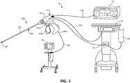
- a dual microwave/RF energy ablation and cutting system 10 is illustrated and generally includes a tissue ablation instrument 100 operably coupled to a microwave generator 12, an electrosurgical generator 14, and a surgical suction pump 16.
- the microwave generator 12 generates a microwave energy signal that is transmitted to a radiating section "R" ( FIG. 2 ) of the surgical instrument 100 via a coaxial cable 102.
- the microwave energy generated by the microwave generator 12 may be in the range of about 915 MHz to about 25.0 GHz. In some embodiments, the microwave generator 12 may operate at 915 MHz, 2450 MHz, and/or 5800 Mhz.
- the electrosurgical generator 14 generates a radiofrequency signal and outputs it to bipolar electrodes 142a, 142b ( FIG.
- the tissue ablation system 10 may further include a source of coolant 18 (e.g., saline) and a pump 20 for conveying the coolant to the surgical instrument 100 to cool various components therein during operation.
- a source of coolant 18 e.g., saline
- a pump 20 for conveying the coolant to the surgical instrument 100 to cool various components therein during operation.
- the surgical instrument 100 of the tissue ablation system 10 includes a handle portion 112 and a shaft assembly 120 extending distally from the handle portion 112.
- the handle portion 112 has a body portion 114 through which each of the coaxial cable 102, the transmission line 104, and the suction tube 106 extend.
- the handle portion 112 includes first and second controls 116a, 116b such as buttons, switches, or triggers, movably coupled to the body portion 114 of the handle portion 112.
- the first control 116a may be in electrical communication (e.g., wirelessly or wired connection) with the microwave generator 12 and configured to selectively actuate a microwave function of the surgical instrument 100
- the second control 116b may be in electrical communication (e.g., wirelessly or wired connection) with the electro surgical generator 14 and configured to selectively actuate a radiofrequency function of the surgical instrument 100.
- an actuation of the microwave function and/or the radiofrequency function of the surgical instrument 100 may be accomplished via a button or a footswitch external to the surgical instrument 100.
- the shaft assembly 120 of the surgical instrument 100 includes a hollow, elongated body or outer shaft 122 and an outer coating or sheath 124 covering an outer surface of the outer shaft 122.
- the outer shaft 122 has a proximal portion 122a coupled to the handle portion 112 and a distal portion 122b.
- the outer shaft 122 defines a longitudinal axis "X" and has a wedge-shaped or triangular cross-sectional profile.
- the outer shaft 122 has a planar base 126a and a pair sides 126b, 126c extending at acute angles downwardly from the base 126a.
- the sides 126b, 126c of the outer shaft 122 form an acuminate apex or edge 128 at the point at which they are adjoined.
- the edge 128 of the outer shaft 122 extends parallel with and along the longitudinal axis "X" thereof and is configured to contact and move along a tissue surface, as will be described.
- the outer shaft 122 may assume any suitable cross-sectional configuration, such as, for example, circular, V-shaped, U-shaped, oval, square, and/or polygonal.
- the distal portion 122b of the outer shaft 122 may be configured to articulate relative to the proximal portion 122a thereof.
- the distal portion 122b of the outer shaft 122 may move relative to the proximal portion 122a between a non-articulated configuration as shown in FIG. 2 , in which the distal portion 122b is coaxial with the longitudinal axis "X" of the outer shaft 122, and an articulated position as shown in FIG. 5 , in which the distal portion 122b extends at a non-zero angle relative to the longitudinal axis "X" of the outer shaft 122.
- distal portion 122b of the outer shaft 122 may be resiliently biased toward the non-articulated position via a biasing member (not shown) or a shape-memory alloy, and may be articulated by applying external pressure on the distal portion 122b.
- articulation wires and articulated segments may be employed to achieve the depicted articulation as is common in the surgical arts.
- the coaxial cable 102 of the surgical instrument 100 extends axially through a channel 130 defined through the outer shaft 122 and has a proximal portion 102a disposed with the proximal portion 122a of the outer shaft 122 and a distal portion 102b disposed within the distal portion 122b of the outer shaft 122.
- the proximal portion 102a of the coaxial cable 102 has a larger diameter, e.g., 1.5X - 3X the diameter of the distal portion 102a, such that the proximal portion 102a is well-suited for dissipating heat therefrom during the transmission of microwave energy therethrough.
- the coaxial cable 102 has an outer conductor 108a, an inner conductor 108b extending coaxially through the outer conductor 108a, and a dielectric 108c disposed between the inner and outer conductors 108a, 108b.
- the inner conductor 108b extends distally beyond a distal end of the outer conductor 108a to form or define the microwave antenna 132, from which microwave energy originating from the microwave generator 12 is emitted radially outward.
- the shaft assembly 120 of the surgical instrument 100 may further include a solid core dielectric region 134 disposed within the distal portion 122b of the outer shaft 122, and a reflector 136 disposed about an upper portion 134b of the dielectric region 134 and about the microwave antenna 132.
- the dielectric region 134 has a bottom portion 134a received between the two lateral sides 126b, 126c of the outer shaft 122, and an upper portion 134b.
- the lower portion 134a of the dielectric region 134 has a generally triangular configuration and the upper portion 134b has a generally semicircular configuration.
- the lower portion 134a includes a bottom acuminate edge 138 through which microwave energy is transmitted.
- the bottom edge 138 of the lower portion 134a is disposed adjacent the edge 128 of the outer shaft 122 and is exposed (i.e., not covered by the reflector 136).
- the upper portion 134b of the dielectric region 134 has the distal portion 102b of the coaxial cable 102 extending therethrough.
- the dielectric region 134 may be formed from any suitable dielectric material having low-loss dielectric loading properties that possesses sufficient mechanical and biocompatible properties to withstand conditions associated with surgical procedures, including without limitation ceramic material; PTFE; Teflon®; or UltemTM amorphous thermoplastic polyetherimide (PEI) resin distributed by SABIC Innovative Plastics of Pittsfield, Mass., USA.
- suitable dielectric material having low-loss dielectric loading properties that possesses sufficient mechanical and biocompatible properties to withstand conditions associated with surgical procedures, including without limitation ceramic material; PTFE; Teflon®; or UltemTM amorphous thermoplastic polyetherimide (PEI) resin distributed by SABIC Innovative Plastics of Pittsfield, Mass., USA.
- the reflector 136 of the shaft assembly 120 surrounds the upper portion 134b of the dielectric region 134 and has a semi-circular shape, which facilitates directing or focusing microwave energy toward the edge 128 of the outer shaft 122.
- the reflector 136 may assume any suitable shape for focusing microwave energy through the dielectric region 134 and toward the edge 128 of the outer shaft 122, such as, for example, parabolic, semi-hemispherical, or the like. It is contemplated that the reflector 136 and the pair of lateral sides 126b, 126c of the outer shaft 122 cooperatively define a cavity 139 therein, which is filled by the dielectric region 134.
- the reflector 136 may be a layer or coating and may be formed from any suitable material having the capability to reflect microwave energy, such as, without limitation, copper plating, copper foil, or PolyflonTM electroplated PTFE.
- the suction tube 106 of the surgical instrument 100 extends axially through the outer shaft 122.
- the tube 106 has a proximal portion 106a coupled to the surgical suction pump 16 and a distal portion 106b disposed radially outward from the microwave antenna 132 and out of the pathway of microwave energy transmitted from the microwave antenna 132.
- the distal portion 106b of the tube 106 extends distally beyond the microwave antenna 132 and terminates adjacent a distal tip of the outer shaft 122.
- the outer shaft 122 and the outer sheath 124 define a port 140 therethrough that is fluidly coupled to the distal portion 106b of the tube 106 such that the port 140 acts as a suction port when the surgical suction pump 16 is activated.
- the shaft assembly 120 of the surgical instrument 100 further includes a pair of bipolar electrodes 142a, 142b disposed within the distal portion 122b of the outer shaft 122 and radially outward from the microwave antenna 132.
- the location of the electrodes 142a, 142b is selected so as to position the electrodes 142a, 142b out of alignment with the pathway of the microwave energy transmitted from the microwave antenna 132.
- the electrodes 142a, 142b are electrically coupled to the electrosurgical generator 14 via the transmission line 104.
- the transmission line 104 splits into two electrode leads 104a, 104b in the outer shaft 122.
- a first electrode 142a of the pair of bipolar electrodes may be disposed on the base 126a of the outer shaft 122, and a second electrode 142b of the pair of bipolar electrodes may be disposed on the second the lateral side 126c of the outer shaft 122, such that the first and second electrodes 142a, 142b are angled relative to one another.
- the first and second electrodes 142a, 142b are in close proximity to one another (e.g., within about 0.025 and 0.050 inches from one another) while remaining electrically insulated along their length.
- the bipolar electrodes 142a, 142b may be disposed distally of the microwave antenna 132. In this way, the microwave energy transmitted from the microwave antenna 132, which is directed perpendicularly relative to the longitudinal axis "X" of the outer shaft 122, will not travel through the distally-located electrodes 142a, 142b.
- a portion of tissue such as a section of liver tissue "T” may be ablated and resected using the tissue ablation system 10 of the present disclosure.
- the edge 128 of the distal portion 122b of the outer shaft 122 may be placed in contact with a surface "S" of the liver tissue "T” to be resected.
- the edge 128 of the outer shaft 122 Due to the acuminate design of the edge 128 of the outer shaft 122, contacting the edge 128 of the outer shaft 122 with the tissue surface "S" forms a depression or valley in the tissue "T.” With the edge 128 of the outer shaft 122 engaged with the tissue "T,” the first control 116a of the handle portion 112 is actuated to activate the microwave function of the surgical instrument 100, whereby the microwave generator 12 transmits microwave energy to the microwave antenna 132 via the coaxial cable 102.
- the reflector 136 of the shaft assembly 120 redirects a portion of the microwave energy towards the edge 138 of the dielectric region 134, the edge 128 of the outer shaft 122, and ultimately into the valley of the tissue "T.”
- the surgical instrument 100 is manipulated to move or slide the edge 128 of the outer shaft 122 along a resection plane "P" of the liver tissue "T,” thereby pre-coagulating the underlying tissue at a depth proportional to the frequency of the microwave energy and the length of time the microwave antenna 132 is activated.
- the outer shaft 122 of the surgical instrument 100 is rotated about the longitudinal axis "X" from approximately 5° - to approximately 180°, and in some embodiments approximately 130°, to engage a second edge 129 ( FIG. 3B ) of the outer shaft 122 with the tissue surface "S" ( FIG. 5 ).
- the second edge 129 is defined by the second lateral side 126c of the outer shaft 122 and the base 126a of the outer shaft 122.
- the outer shaft 122 of the surgical instrument 100 is tilted toward the distal tip of the outer shaft 122 rather than be rotated about the longitudinal axis "X.”
- the second control 116b is actuated to activate the radiofrequency function of the surgical instrument, whereby the electrosurgical generator 14 transmits radiofrequency energy to the bipolar electrodes 142a, 142b via the electrode leads 104a, 104b.
- the radiofrequency energy is directed out of the second edge 129 of the outer shaft 122 to resect the liver tissue "T" along the resection plane "P.”
- the above-noted steps may be repeated to pre-coagulate the tissue "T" at increasingly greater depths, and then resect along the pre-coagulation line until a desired portion of the tissue "T” is separated from the remainder of the organ.
- the surgical suction pump 16 may be activated at any point during and/or after the procedure to remove surgical debris and/or surgical smoke via the port 140 of the surgical instrument 100.
- system 210 is similar to the tissue ablation system 10 described above with reference to FIGS. 1-5 . Due to the similarity between the tissue ablation systems 10, 210 of the present disclosure, only those details viewed as important in elucidating selected differences between the two ablation systems 10, 210 will be described in detail.
- the dual microwave/RF energy ablation system 210 generally includes a tissue ablation instrument 200 operably coupled to the microwave generator 12, the radiofrequency generator 14, and the surgical suction pump 16.
- the microwave generator 12 generates a microwave signal and outputs it to a microwave antenna 232 of the surgical instrument 200 via a coaxial cable 202.
- the electrosurgical generator 14 generates a radiofrequency signal and outputs it to a monopolar electrode 242 of the surgical instrument 200 via a transmission line 204.
- a return signal, originating from the transmission line 204, may be received by a ground pad 205 coupled to the electrosurgical generator 14.
- the surgical suction pump 16 produces suction and applies the suction to a port 240 located a distal portion of the surgical instrument 200 via a suction tube 206.
- the tissue ablation system 210 may further include a coolant 18 (e.g., saline) and a pump 20 for conveying the coolant to the surgical instrument 200 to cool various components therein during operation.
- a coolant 18 e.g
- the surgical instrument 200 of the tissue ablation system 210 includes a handle portion 212 and a shaft assembly 220 extending distally from the handle portion 212.
- the shaft assembly 220 includes a hollow, elongated body or outer shaft 222 and an outer coating or sheath 224 covering an outer surface of the outer shaft 222.
- the outer sheath 224 is operably coupled to a control 216, such as a button, switch, or trigger, of the handle portion 212.
- the outer sheath 224 in response to an actuation of the control 216, axially moves relative to the handle portion 212 and the outer shaft 222 between a proximal position and a distal position to selectively expose a hook-shaped monopolar electrode 242 of the surgical instrument 200, as will be described in detail below.
- the shaft assembly 220 further includes a coaxial cable 202 that forms the microwave antenna 232 at its terminal end.
- the microwave antenna 232 and its associated components are similar to the microwave antenna 132 described above, and will therefore not be described in further detail herein.
- the monopolar electrode 242 is disposed between an outer surface of the outer shaft 222 and an inner surface of the outer sheath 224, and is electrically coupled to the electrosurgical generator 14.
- the monopolar electrode 242 has a proximal portion 242a in communication with the transmission line 204, and a distal portion 242b extending distally beyond the microwave antenna 232.
- the proximal portion 242a of the monopolar electrode 242 may be mechanically coupled to the control 216 such that an actuation of the control 216 moves the monopolar electrode 242 between proximal and distal positions relative to the outer sheath 224.
- the distal portion 242b of the monopolar electrode 242 may have a hooked configuration for depressing tissue upon contact therewith.
- the distal portion 242b extends at a perpendicular angle relative to the longitudinal axis defined by the outer shaft 222.
- the distal portion 242b of the monopolar electrode 242 may extend at a variety of angles relative to the longitudinal axis of the outer shaft 222, e.g., 0° to 180°.
- the distal portion 242b may assume a helical configuration, a curved configuration, or the like.
- a portion of tissue such as a section of liver tissue "T” may be ablated and resected using the tissue ablation system 210 of the present disclosure.
- tissue ablation system 210 of the present disclosure.
- an edge of the distal portion of the outer shaft 222 may be placed in contact with a surface "S" of the liver tissue "T” to be resected.
- the handle portion 212 is actuated to activate the microwave function of the surgical instrument 200, whereby the microwave generator 12 transmits microwave energy to the microwave antenna 232 via the coaxial cable 202.
- the microwave antenna 232 directs the microwave energy radially outward therefrom and toward the edge of the outer shaft 222 and into the valley formed in the tissue "T.” As the microwave energy is transmitted into the valley of the tissue "T,” the surgical instrument 200 is manipulated to move or slide the edge of the outer shaft 222 along a resection plane "P" of the liver tissue "T,” thereby pre-coagulating the underlying tissue at a depth proportional to the frequency of the microwave energy and the length of time the microwave antenna 232 is activated.
- Movement of the edge of the outer shaft 222 of the surgical instrument 200 along the resection plane "P" is continued until a desired depth and/or width of tissue pre-coagulation is achieved.
- transmission of the microwave energy is deactivated and the outer sheath 224 of the shaft assembly 220 is moved proximally toward the proximal position to expose the distal portion 242b of the monopolar electrode 242.
- the monopolar electrode 242 may be moved distally beyond the outer sheath 224. With the distal portion 242b of the monopolar electrode 242 exposed, the distal portion 242b of the monopolar electrode 242 contacts the tissue surface "S" of the pre-coagulated tissue along the resection plane "P.”
- the control 216 of the handle portion 212 is actuated to activate the radiofrequency function of the surgical instrument 200, whereby the electrosurgical generator 14 transmits radiofrequency energy to the monopolar electrode 242, whereby the radiofrequency energy is directed into the liver tissue "T” to resect the liver tissue "T” along the resection plane "P.”
- the above-noted steps may be repeated to pre-coagulate the tissue "T” at increasingly greater depths until the desired volume of the tissue "T” is pre-coagulated and resected from the remainder of the organ.
- the surgical suction pump 16 may be activated at any point during and/or after the procedure to remove surgical debris and/or surgical smoke via the port 240 of the surgical instrument 200.
- tissue ablation systems are capable of directing microwave and radiofrequency energy into tissue, and may be suitable for use in a variety of procedures and operations.
- the above-described tissue ablation systems may be suitable for utilization with hand-assisted, endoscopic, and laparoscopic surgical procedures.
- the above-described tissue ablation systems may also be suitable for utilization in open surgical applications.
- CT computed tomographic
Landscapes
- Health & Medical Sciences (AREA)
- Surgery (AREA)
- Life Sciences & Earth Sciences (AREA)
- Engineering & Computer Science (AREA)
- Biomedical Technology (AREA)
- Molecular Biology (AREA)
- Nuclear Medicine, Radiotherapy & Molecular Imaging (AREA)
- Veterinary Medicine (AREA)
- Physics & Mathematics (AREA)
- Heart & Thoracic Surgery (AREA)
- Medical Informatics (AREA)
- Otolaryngology (AREA)
- Animal Behavior & Ethology (AREA)
- General Health & Medical Sciences (AREA)
- Public Health (AREA)
- Plasma & Fusion (AREA)
- Electromagnetism (AREA)
- Surgical Instruments (AREA)
Abstract
Description
- The present disclosure relates to a tissue ablation system, and more particularly to a combination microwave/radiofrequency ablation system for coagulating and resecting tissues.
- Electrosurgical devices utilizing electromagnetic radiation have been developed for a variety of uses and applications. Typically, apparatus for use in ablation procedures include a power generation source, e.g., a microwave or radio frequency (RF) electrosurgical generator that functions as an energy source and a surgical instrument (e.g., microwave ablation probe having an antenna assembly) for directing energy to the target tissue. The generator and surgical instrument are typically operatively coupled by a cable assembly having a plurality of conductors for transmitting energy from the generator to the instrument, and for communicating control, feedback, and identification signals between the instrument and the generator.
- There are several types of microwave probes in use, e.g., monopole, dipole, and helical, which may be used in tissue ablation applications. In monopole and dipole antenna assemblies, microwave energy generally radiates perpendicularly away from the axis of the conductor. Monopole antenna assemblies typically include a single, elongated conductor. A typical dipole antenna assembly includes two elongated conductors that are linearly-aligned and positioned end-to-end relative to one another with an electrical insulator placed therebetween. Helical antenna assemblies include helically-shaped conductor configurations of various dimensions, e.g., diameter and length. The main modes of operation of a helical antenna assembly are normal mode (broadside), in which the field radiated by the helix is maximum in a perpendicular plane to the helix axis, and axial mode (end fire), in which maximum radiation is along the helix axis.
- One use for a microwave probe is to dissect solid organs, such as liver or kidney, to remove entire diseased portions of the organ. During these procedures, it is important that blood loss from the dissected organ is minimized without compromising the efficacy of the procedure. It is also of particular importance to keep the procedure simple by reducing the number of surgical instruments used while also keeping the overall procedure time at a minimum.
- Accordingly, it would be advantageous to provide one surgical instrument that performs a plurality of tasks during a tissue ablation procedure to effectively dissect a diseased portion of a solid organ.
- In one aspect of the present disclosure, a surgical instrument for ablating tissue is provided and includes a handle portion and a shaft assembly extending distally from the handle portion. The shaft assembly includes an outer shaft, a coaxial cable extending through the outer shaft, and an electrode coupled to a distal portion of the outer shaft. The coaxial cable has a distal portion disposed within the distal portion of the outer shaft. The distal portion of the coaxial cable forms a microwave antenna configured to transmit microwave energy radially outward and through the outer shaft. An actuation of the handle portion activates the transmission of the microwave energy from the microwave antenna or the transmission of the radiofrequency energy from the at least one electrode.
- In some embodiments, the electrode may be disposed distally of the microwave antenna.
- In some embodiments, the electrode may be disposed radially outward from the microwave antenna and out of alignment with the direction of travel of the microwave energy transmitted from the microwave antenna. The electrode may be a pair of bipolar electrodes.
- In some embodiments, the distal portion of the outer shaft may have a wedge-shaped configuration.
- In some embodiments, the shaft assembly may further include a reflector disposed within the distal portion of the outer shaft and about the microwave antenna.
- In some embodiments, the reflector may have a semi-circular shape and be configured to direct the transmission of the microwave energy toward an edge of the outer shaft. The edge of the outer shaft may extend parallel with a longitudinal axis defined by the shaft assembly.
- In some embodiments, the shaft assembly may further include a dielectric region disposed within the distal portion of the outer shaft.
- In some embodiments, the reflector and a pair of adjoined lateral sides of the outer shaft may cooperatively define a cavity therein. The dielectric region may fill the cavity.
- In some embodiments, the surgical instrument may further include a tube extending through the outer shaft and may be disposed radially outward from the microwave antenna. The tube may have a proximal portion configured to receive suction.
- In some embodiments, the electrode may include a hooked distal portion disposed distally of the microwave antenna. The shaft assembly may further include an outer sheath disposed about the outer shaft and may be axially movable relative to the outer shaft between a first position, in which the hooked distal portion is disposed within the outer sheath, and a second position, in which the hooked distal portion is disposed distally of the outer sheath.
- In another aspect of the present disclosure, a tissue ablation system is provided and includes a microwave generator configured to generate and transmit microwave energy, an electrosurgical generator configured to generate and transmit radiofrequency energy, and a surgical instrument. The surgical instrument includes a handle portion configured to be coupled to both of the microwave and electrosurgical generators, and a shaft assembly extending distally from the handle portion. The shaft assembly includes an outer shaft, a coaxial cable extending through the outer shaft, and an electrode coupled to a distal portion of the outer shaft. The coaxial cable has a proximal portion configured to be in electrical communication with the microwave generator, and a distal portion disposed within the distal portion of the outer shaft. The distal portion of the coaxial cable forms a microwave antenna configured to transmit the microwave energy radially outward and through the outer shaft. The electrode is coupled to the distal portion of the outer shaft and configured to be in electrical communication with the electrosurgical generator to transmit the radiofrequency energy. An actuation of the handle portion activates the transmission of the microwave energy from the microwave antenna or the transmission of the radiofrequency energy from the electrode.
- In yet another aspect of the present disclosure, a method of resecting a portion of tissue is provided and includes positioning a microwave antenna of a surgical instrument adjacent a portion of tissue, transmitting microwave energy into the portion of the tissue, thereby precoagulating the portion of the tissue, deactivating the transmission of the microwave energy, and moving a distal portion of an outer shaft of the surgical instrument along the tissue while transmitting radiofrequency energy from an electrode of the surgical instrument into the tissue, thereby resecting the portion of the tissue.
- As used herein, the terms parallel and perpendicular are understood to include relative configurations that are substantially parallel and substantially perpendicular up to about + or - 10 degrees from true parallel and true perpendicular.
- The accompanying drawings, which are incorporated in and constitute a part of this specification, illustrate embodiments of the disclosure and, together with a general description of the disclosure given above, and the detailed description of the embodiment(s) given below, serve to explain the principles of the disclosure, wherein:
-
FIG. 1 is perspective view of a tissue ablation system including a surgical instrument, an electrosurgical generator, a microwave generator, and a surgical suction pump in accordance with the principles of the present disclosure; -
FIG. 2 is a side view of the surgical instrument ofFIG. 1 , illustrating a microwave antenna disposed at a distal portion of a shaft assembly; -
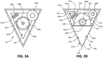
FIG. 3A is a cross-section, taken alongline 3A-3A ofFIG. 2 , of a proximal portion of the shaft assembly; -
FIG. 3B is a cross-section, taken alongline 3B-3B ofFIG. 2 , of a distal portion of the shaft assembly; -
FIG. 4 is a side view of another embodiment of a shaft assembly having bipolar electrodes disposed distally of a microwave antenna; -
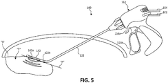
FIG. 5 is a perspective view of the surgical instrument ofFIG. 4 , illustrating an exemplary ablation procedure; -
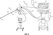
FIG. 6 is a perspective view of another embodiment of a tissue ablation system including a surgical instrument, an electrosurgical generator, a microwave generator, and a surgical suction pump in accordance with the principles of the present disclosure; -
FIG. 7 is a side view of the surgical instrument ofFIG. 6 , illustrating an outer sheath covering a monopolar electrode; -
FIG. 8 is a side view of the surgical instrument ofFIG. 6 , illustrating the monopolar electrode disposed outside of the outer sheath; and -
FIG. 9 is a perspective view of the surgical instrument ofFIG. 6 , illustrating an exemplary ablation procedure. - Embodiments of the presently disclosed tissue ablation systems including various embodiments of a surgical instrument and methods of use thereof are described in detail with reference to the drawings, in which like reference numerals designate identical or corresponding elements in each of the several views. As used herein the term "distal" refers to that portion of the tissue ablation system or component thereof, that is closer to the patient, while the term "proximal" refers to that portion of the tissue ablation system or component thereof, that is farther from the patient.
- As will be described in detail below, provided are embodiments of a surgical instrument of a tissue ablation system that switches between microwave energy transmission and radiofrequency energy transmission. For example, one embodiment of the disclosed surgical instruments includes a wedge-shaped outer shaft, a microwave antenna disposed within a distal portion of the outer shaft, and a monopolar electrode or bipolar electrodes disposed on the distal portion of the outer shaft. In operation, the microwave antenna is activated to transmit microwave energy out of an apex of the outer shaft and into tissue to precoagulate tissue. After the tissue is precoagulated, the microwave antenna is deactivated, and the electrode is activated to transmit radiofrequency energy into the tissue while moving the distal portion of the outer shaft along an outer surface of the tissue. The radiofrequency energy cuts or resects the precoagulated tissue to remove a portion of the tissue with minimal to no bleeding occurring.
- As used herein, the term "pre-coagulate" means heating tissue to the extent necessary to prevent blood from flowing from the heated tissue upon resecting the tissue.
- As used herein, "microwave" generally refers to electromagnetic waves in the frequency range of 300 megahertz (MHz) (3 x 10⁸ cycles/second) to 300 gigahertz (GHz) (3 x 10¹¹ cycles/second).
- As used herein, "tissue ablation" generally refers to any ablation procedure, such as, for example, microwave ablation, radiofrequency (RF) ablation, or microwave or RF ablation-assisted resection.
- As used herein, "transmission line" generally refers to any transmission medium that can be used for the propagation of signals from one point to another.
- As used herein, "fluid" generally refers to a liquid, a gas or both.
- As used herein, "controller" generally refers to any electrical device that employs digital and/or analog components to generate digital and/or analog signals to control or drive another device. The term "controller" may refer to a digital signal processor, a microcontroller, or a computer having a processor, a memory, and input/output ports for carrying out some of the methods described herein.
- Various embodiments of the presently disclosed surgical instruments are suitable for tissue ablation and for use to pre-coagulate tissue for microwave ablation-assisted surgical resection. Although various methods described hereinbelow are targeted toward microwave ablation and the destruction and/or resection of targeted tissue, methods for directing electromagnetic radiation may be used with other therapies in which the target tissue is partially destroyed, damaged, or dissected. In addition, the teachings of the present disclosure may apply to a dipole, monopole, helical, or other suitable type of microwave antenna.
- With reference to
FIG. 1 , a dual microwave/RF energy ablation and cutting system 10 is illustrated and generally includes atissue ablation instrument 100 operably coupled to amicrowave generator 12, anelectrosurgical generator 14, and asurgical suction pump 16. Themicrowave generator 12 generates a microwave energy signal that is transmitted to a radiating section "R" (FIG. 2 ) of thesurgical instrument 100 via acoaxial cable 102. The microwave energy generated by themicrowave generator 12 may be in the range of about 915 MHz to about 25.0 GHz. In some embodiments, themicrowave generator 12 may operate at 915 MHz, 2450 MHz, and/or 5800 Mhz. Theelectrosurgical generator 14 generates a radiofrequency signal and outputs it tobipolar electrodes FIG. 3B ) of thesurgical instrument 100 via atransmission line 104. Thesurgical suction pump 16 produces suction and applies the suction to a port 140 (FIG. 2 ) located a distal portion of thesurgical instrument 100 via asuction tube 106. In some embodiments, the tissue ablation system 10 may further include a source of coolant 18 (e.g., saline) and apump 20 for conveying the coolant to thesurgical instrument 100 to cool various components therein during operation. - The
surgical instrument 100 of the tissue ablation system 10 includes ahandle portion 112 and ashaft assembly 120 extending distally from thehandle portion 112. Thehandle portion 112 has abody portion 114 through which each of thecoaxial cable 102, thetransmission line 104, and thesuction tube 106 extend. Thehandle portion 112 includes first andsecond controls body portion 114 of thehandle portion 112. Thefirst control 116a may be in electrical communication (e.g., wirelessly or wired connection) with themicrowave generator 12 and configured to selectively actuate a microwave function of thesurgical instrument 100, and thesecond control 116b may be in electrical communication (e.g., wirelessly or wired connection) with the electrosurgical generator 14 and configured to selectively actuate a radiofrequency function of thesurgical instrument 100. In some embodiments, an actuation of the microwave function and/or the radiofrequency function of thesurgical instrument 100 may be accomplished via a button or a footswitch external to thesurgical instrument 100. - With reference to
FIGS. 1 ,2 ,3A, and 3B , theshaft assembly 120 of thesurgical instrument 100 includes a hollow, elongated body orouter shaft 122 and an outer coating orsheath 124 covering an outer surface of theouter shaft 122. Theouter shaft 122 has aproximal portion 122a coupled to thehandle portion 112 and adistal portion 122b. Theouter shaft 122 defines a longitudinal axis "X" and has a wedge-shaped or triangular cross-sectional profile. Theouter shaft 122 has aplanar base 126a and a pair sides 126b, 126c extending at acute angles downwardly from thebase 126a. Thesides outer shaft 122 form an acuminate apex or edge 128 at the point at which they are adjoined. Theedge 128 of theouter shaft 122 extends parallel with and along the longitudinal axis "X" thereof and is configured to contact and move along a tissue surface, as will be described. In some embodiments, theouter shaft 122 may assume any suitable cross-sectional configuration, such as, for example, circular, V-shaped, U-shaped, oval, square, and/or polygonal. - The
distal portion 122b of theouter shaft 122 may be configured to articulate relative to theproximal portion 122a thereof. In particular, thedistal portion 122b of theouter shaft 122 may move relative to theproximal portion 122a between a non-articulated configuration as shown inFIG. 2 , in which thedistal portion 122b is coaxial with the longitudinal axis "X" of theouter shaft 122, and an articulated position as shown inFIG. 5 , in which thedistal portion 122b extends at a non-zero angle relative to the longitudinal axis "X" of theouter shaft 122. It is contemplated that thedistal portion 122b of theouter shaft 122 may be resiliently biased toward the non-articulated position via a biasing member (not shown) or a shape-memory alloy, and may be articulated by applying external pressure on thedistal portion 122b. Alternatively, articulation wires and articulated segments may be employed to achieve the depicted articulation as is common in the surgical arts. - With reference to
FIGS. 3A and 3B , thecoaxial cable 102 of thesurgical instrument 100 extends axially through achannel 130 defined through theouter shaft 122 and has aproximal portion 102a disposed with theproximal portion 122a of theouter shaft 122 and adistal portion 102b disposed within thedistal portion 122b of theouter shaft 122. Theproximal portion 102a of thecoaxial cable 102 has a larger diameter, e.g., 1.5X - 3X the diameter of thedistal portion 102a, such that theproximal portion 102a is well-suited for dissipating heat therefrom during the transmission of microwave energy therethrough. Thecoaxial cable 102 has anouter conductor 108a, aninner conductor 108b extending coaxially through theouter conductor 108a, and a dielectric 108c disposed between the inner andouter conductors inner conductor 108b extends distally beyond a distal end of theouter conductor 108a to form or define themicrowave antenna 132, from which microwave energy originating from themicrowave generator 12 is emitted radially outward. - The
shaft assembly 120 of thesurgical instrument 100 may further include a solid coredielectric region 134 disposed within thedistal portion 122b of theouter shaft 122, and areflector 136 disposed about anupper portion 134b of thedielectric region 134 and about themicrowave antenna 132. Thedielectric region 134 has abottom portion 134a received between the twolateral sides outer shaft 122, and anupper portion 134b. Thelower portion 134a of thedielectric region 134 has a generally triangular configuration and theupper portion 134b has a generally semicircular configuration. Thelower portion 134a includes a bottomacuminate edge 138 through which microwave energy is transmitted. Thebottom edge 138 of thelower portion 134a is disposed adjacent theedge 128 of theouter shaft 122 and is exposed (i.e., not covered by the reflector 136). Theupper portion 134b of thedielectric region 134 has thedistal portion 102b of thecoaxial cable 102 extending therethrough. - The
dielectric region 134 may be formed from any suitable dielectric material having low-loss dielectric loading properties that possesses sufficient mechanical and biocompatible properties to withstand conditions associated with surgical procedures, including without limitation ceramic material; PTFE; Teflon®; or Ultem™ amorphous thermoplastic polyetherimide (PEI) resin distributed by SABIC Innovative Plastics of Pittsfield, Mass., USA. - The
reflector 136 of theshaft assembly 120 surrounds theupper portion 134b of thedielectric region 134 and has a semi-circular shape, which facilitates directing or focusing microwave energy toward theedge 128 of theouter shaft 122. In some embodiments, thereflector 136 may assume any suitable shape for focusing microwave energy through thedielectric region 134 and toward theedge 128 of theouter shaft 122, such as, for example, parabolic, semi-hemispherical, or the like. It is contemplated that thereflector 136 and the pair oflateral sides outer shaft 122 cooperatively define a cavity 139 therein, which is filled by thedielectric region 134. Thereflector 136 may be a layer or coating and may be formed from any suitable material having the capability to reflect microwave energy, such as, without limitation, copper plating, copper foil, or Polyflon™ electroplated PTFE. - With reference to
FIGS. 2 ,3A, and 3B , thesuction tube 106 of thesurgical instrument 100 extends axially through theouter shaft 122. Thetube 106 has aproximal portion 106a coupled to thesurgical suction pump 16 and adistal portion 106b disposed radially outward from themicrowave antenna 132 and out of the pathway of microwave energy transmitted from themicrowave antenna 132. Thedistal portion 106b of thetube 106 extends distally beyond themicrowave antenna 132 and terminates adjacent a distal tip of theouter shaft 122. Theouter shaft 122 and theouter sheath 124 define aport 140 therethrough that is fluidly coupled to thedistal portion 106b of thetube 106 such that theport 140 acts as a suction port when thesurgical suction pump 16 is activated. - With reference to
FIGS. 3A and 3B , theshaft assembly 120 of thesurgical instrument 100 further includes a pair ofbipolar electrodes distal portion 122b of theouter shaft 122 and radially outward from themicrowave antenna 132. The location of theelectrodes electrodes microwave antenna 132. Theelectrodes electrosurgical generator 14 via thetransmission line 104. Thetransmission line 104 splits into twoelectrode leads outer shaft 122. Afirst electrode 142a of the pair of bipolar electrodes may be disposed on thebase 126a of theouter shaft 122, and asecond electrode 142b of the pair of bipolar electrodes may be disposed on the second thelateral side 126c of theouter shaft 122, such that the first andsecond electrodes second electrodes - As illustrated in the embodiment of
FIG. 4 , instead of positioning thebipolar electrodes microwave antenna 132, thebipolar electrodes microwave antenna 132. In this way, the microwave energy transmitted from themicrowave antenna 132, which is directed perpendicularly relative to the longitudinal axis "X" of theouter shaft 122, will not travel through the distally-locatedelectrodes - In operation, as shown in
FIG. 5 , a portion of tissue, such as a section of liver tissue "T" may be ablated and resected using the tissue ablation system 10 of the present disclosure. Theedge 128 of thedistal portion 122b of theouter shaft 122 may be placed in contact with a surface "S" of the liver tissue "T" to be resected. Due to the acuminate design of theedge 128 of theouter shaft 122, contacting theedge 128 of theouter shaft 122 with the tissue surface "S" forms a depression or valley in the tissue "T." With theedge 128 of theouter shaft 122 engaged with the tissue "T," thefirst control 116a of thehandle portion 112 is actuated to activate the microwave function of thesurgical instrument 100, whereby themicrowave generator 12 transmits microwave energy to themicrowave antenna 132 via thecoaxial cable 102. - The
reflector 136 of theshaft assembly 120 redirects a portion of the microwave energy towards theedge 138 of thedielectric region 134, theedge 128 of theouter shaft 122, and ultimately into the valley of the tissue "T." As the microwave energy is transmitted into the valley of the tissue "T," thesurgical instrument 100 is manipulated to move or slide theedge 128 of theouter shaft 122 along a resection plane "P" of the liver tissue "T," thereby pre-coagulating the underlying tissue at a depth proportional to the frequency of the microwave energy and the length of time themicrowave antenna 132 is activated. - Movement of the
edge 128 of theouter shaft 122 of thesurgical instrument 100 along the resection plane "P" is continued until a desired depth and/or width of pre-coagulation is achieved. Upon achieving the desired depth and width of tissue pre-coagulation, transmission of the microwave energy is deactivated and thebipolar electrodes - As shown in
FIG. 3A in conjunction withFIG. 2 , to orient thebipolar electrodes FIG. 5 ) theouter shaft 122 of thesurgical instrument 100 is rotated about the longitudinal axis "X" from approximately 5° - to approximately 180°, and in some embodiments approximately 130°, to engage a second edge 129 (FIG. 3B ) of theouter shaft 122 with the tissue surface "S" (FIG. 5 ). Thesecond edge 129 is defined by the secondlateral side 126c of theouter shaft 122 and thebase 126a of theouter shaft 122. In the embodiment illustrated inFIG. 4 , to orient thebipolar electrodes outer shaft 122 of thesurgical instrument 100 is tilted toward the distal tip of theouter shaft 122 rather than be rotated about the longitudinal axis "X." - While moving the
second edge 129 of theouter shaft 122 along the resection plane "P," thesecond control 116b is actuated to activate the radiofrequency function of the surgical instrument, whereby theelectrosurgical generator 14 transmits radiofrequency energy to thebipolar electrodes second edge 129 of theouter shaft 122 to resect the liver tissue "T" along the resection plane "P." - The above-noted steps may be repeated to pre-coagulate the tissue "T" at increasingly greater depths, and then resect along the pre-coagulation line until a desired portion of the tissue "T" is separated from the remainder of the organ. The
surgical suction pump 16 may be activated at any point during and/or after the procedure to remove surgical debris and/or surgical smoke via theport 140 of thesurgical instrument 100. By pre-coagulating the tissue using microwave energy, blood loss is minimized since the resection line for the bi-polar resection or cutting is within the boundaries of the pre-coagulated tissue. Further, this procedure reduces the opportunities for reseeding of cancerous tissue by this same pre-coagulation process prior to any resection or cutting of the organ. - With reference to
FIGS. 6-9 , another embodiment of a dual microwave/RF energy ablation system is illustrated assystem 210, which is similar to the tissue ablation system 10 described above with reference toFIGS. 1-5 . Due to the similarity between thetissue ablation systems 10, 210 of the present disclosure, only those details viewed as important in elucidating selected differences between the twoablation systems 10, 210 will be described in detail. - The dual microwave/RF
energy ablation system 210 generally includes atissue ablation instrument 200 operably coupled to themicrowave generator 12, theradiofrequency generator 14, and thesurgical suction pump 16. Themicrowave generator 12 generates a microwave signal and outputs it to amicrowave antenna 232 of thesurgical instrument 200 via acoaxial cable 202. Theelectrosurgical generator 14 generates a radiofrequency signal and outputs it to amonopolar electrode 242 of thesurgical instrument 200 via atransmission line 204. A return signal, originating from thetransmission line 204, may be received by aground pad 205 coupled to theelectrosurgical generator 14. Thesurgical suction pump 16 produces suction and applies the suction to aport 240 located a distal portion of thesurgical instrument 200 via asuction tube 206. In some embodiments, thetissue ablation system 210 may further include a coolant 18 (e.g., saline) and apump 20 for conveying the coolant to thesurgical instrument 200 to cool various components therein during operation. - The
surgical instrument 200 of thetissue ablation system 210 includes ahandle portion 212 and ashaft assembly 220 extending distally from thehandle portion 212. Theshaft assembly 220 includes a hollow, elongated body orouter shaft 222 and an outer coating orsheath 224 covering an outer surface of theouter shaft 222. Theouter sheath 224 is operably coupled to acontrol 216, such as a button, switch, or trigger, of thehandle portion 212. Theouter sheath 224, in response to an actuation of thecontrol 216, axially moves relative to thehandle portion 212 and theouter shaft 222 between a proximal position and a distal position to selectively expose a hook-shapedmonopolar electrode 242 of thesurgical instrument 200, as will be described in detail below. - The
shaft assembly 220 further includes acoaxial cable 202 that forms themicrowave antenna 232 at its terminal end. Themicrowave antenna 232 and its associated components (e.g., a reflector and dielectric region) are similar to themicrowave antenna 132 described above, and will therefore not be described in further detail herein. Themonopolar electrode 242 is disposed between an outer surface of theouter shaft 222 and an inner surface of theouter sheath 224, and is electrically coupled to theelectrosurgical generator 14. Themonopolar electrode 242 has aproximal portion 242a in communication with thetransmission line 204, and adistal portion 242b extending distally beyond themicrowave antenna 232. In some embodiments, theproximal portion 242a of themonopolar electrode 242 may be mechanically coupled to thecontrol 216 such that an actuation of thecontrol 216 moves themonopolar electrode 242 between proximal and distal positions relative to theouter sheath 224. - The
distal portion 242b of themonopolar electrode 242 may have a hooked configuration for depressing tissue upon contact therewith. In particular, thedistal portion 242b extends at a perpendicular angle relative to the longitudinal axis defined by theouter shaft 222. In some embodiments, thedistal portion 242b of themonopolar electrode 242 may extend at a variety of angles relative to the longitudinal axis of theouter shaft 222, e.g., 0° to 180°. In other embodiments, rather than thedistal portion 242b of themonopolar electrode 242 assuming a hooked configuration, thedistal portion 242b may assume a helical configuration, a curved configuration, or the like. - In operation, as shown in
FIG. 9 , a portion of tissue, such as a section of liver tissue "T" may be ablated and resected using thetissue ablation system 210 of the present disclosure. With theouter sheath 224 of thesurgical instrument 200 covering thedistal portion 242b of themonopolar electrode 242b, an edge of the distal portion of theouter shaft 222 may be placed in contact with a surface "S" of the liver tissue "T" to be resected. Contacting the edge of theouter shaft 222 with the tissue surface "S" forms a depression or valley in the tissue "T." Thehandle portion 212 is actuated to activate the microwave function of thesurgical instrument 200, whereby themicrowave generator 12 transmits microwave energy to themicrowave antenna 232 via thecoaxial cable 202. - The
microwave antenna 232 directs the microwave energy radially outward therefrom and toward the edge of theouter shaft 222 and into the valley formed in the tissue "T." As the microwave energy is transmitted into the valley of the tissue "T," thesurgical instrument 200 is manipulated to move or slide the edge of theouter shaft 222 along a resection plane "P" of the liver tissue "T," thereby pre-coagulating the underlying tissue at a depth proportional to the frequency of the microwave energy and the length of time themicrowave antenna 232 is activated. - Movement of the edge of the
outer shaft 222 of thesurgical instrument 200 along the resection plane "P" is continued until a desired depth and/or width of tissue pre-coagulation is achieved. Upon achieving the desired depth and width of tissue pre-coagulation, transmission of the microwave energy is deactivated and theouter sheath 224 of theshaft assembly 220 is moved proximally toward the proximal position to expose thedistal portion 242b of themonopolar electrode 242. In some embodiments, instead of moving theouter sheath 242 proximally to expose the monopolar electrodedistal portion 242b, themonopolar electrode 242 may be moved distally beyond theouter sheath 224. With thedistal portion 242b of themonopolar electrode 242 exposed, thedistal portion 242b of themonopolar electrode 242 contacts the tissue surface "S" of the pre-coagulated tissue along the resection plane "P." - While moving the
monopolar electrode 242 along the resection plane "P," thecontrol 216 of thehandle portion 212 is actuated to activate the radiofrequency function of thesurgical instrument 200, whereby theelectrosurgical generator 14 transmits radiofrequency energy to themonopolar electrode 242, whereby the radiofrequency energy is directed into the liver tissue "T" to resect the liver tissue "T" along the resection plane "P." - The above-noted steps may be repeated to pre-coagulate the tissue "T" at increasingly greater depths until the desired volume of the tissue "T" is pre-coagulated and resected from the remainder of the organ. The
surgical suction pump 16 may be activated at any point during and/or after the procedure to remove surgical debris and/or surgical smoke via theport 240 of thesurgical instrument 200. - The above-described tissue ablation systems are capable of directing microwave and radiofrequency energy into tissue, and may be suitable for use in a variety of procedures and operations. The above-described tissue ablation systems may be suitable for utilization with hand-assisted, endoscopic, and laparoscopic surgical procedures. The above-described tissue ablation systems may also be suitable for utilization in open surgical applications.
- An effective method of identifying cancerous or diseased target tissue involves the use of a computed tomographic (CT) image. The use of CT as a diagnostic tool has now become routine and CT results are now frequently the primary source of information available to the practitioner regarding the size and location of a lesion. This information is used by the practitioner in planning an operative procedure such as a biopsy, but is only available as "offline" information which must typically be memorized to the best of the practitioner's ability prior to beginning a procedure. In addition to inputting target information, integration with the CT data provides improved system functionality, thereby greatly facilitating the planning of a pathway to an identified target as well as providing the ability to navigate through the body to the target location.
- Although embodiments have been described in detail with reference to the accompanying drawings for the purpose of illustration and description, it is to be understood that the inventive processes and apparatus are not to be construed as limited thereby. It will be apparent to those of ordinary skill in the art that various modifications to the foregoing embodiments may be made without departing from the scope of the disclosure.
- The invention may be described by reference to the following numbered paragraphs:-
- 1. A surgical instrument for ablating tissue, comprising:
- a handle portion; and
- a shaft assembly extending distally from the handle portion and including:
- an outer shaft having a distal portion;
- a coaxial cable extending through the outer shaft and having a distal portion disposed within the distal portion of the outer shaft, the distal portion of the coaxial cable forming a microwave antenna configured to transmit microwave energy radially outward and through the outer shaft; and
- at least one electrode coupled to the distal portion of the outer shaft and configured to transmit radiofrequency energy, wherein an actuation of the surgical instrument activates at least one of the transmission of the microwave energy from the microwave antenna or the transmission of the radiofrequency energy from the at least one electrode.
- 2. The surgical instrument according to paragraph 1, wherein the at least one electrode is disposed distally of the microwave antenna.
- 3. The surgical instrument according to paragraph 1, wherein the at least one electrode is disposed radially outward from the microwave antenna and out of alignment with the direction of travel of the microwave energy being transmitted from the microwave antenna.
- 4. The surgical instrument according to paragraph 1, wherein the at least one electrode is a pair of bipolar electrodes.
- 5. The surgical instrument according to paragraph 1, wherein the distal portion of the outer shaft has a wedge-shaped configuration.
- 6. The surgical instrument according to
paragraph 5, wherein the shaft assembly further includes a reflector disposed within the distal portion of the outer shaft and about the microwave antenna. - 7. The surgical instrument according to paragraph 6, wherein the reflector has a semi-circular shape and is configured to direct the transmission of the microwave energy toward an edge of the outer shaft, the edge of the outer shaft extending parallel with a longitudinal axis defined by the shaft assembly.
- 8. The surgical instrument according to paragraph 7, wherein the shaft assembly further includes a dielectric region disposed within the distal portion of the outer shaft.
- 9. The surgical instrument according to paragraph 8, wherein the reflector and a pair of adjoined lateral sides of the outer shaft cooperatively define a cavity therein, the dielectric region filling the cavity.
- 10. The surgical instrument according to paragraph 1, further comprising a tube extending through the outer shaft and disposed radially outward from the microwave antenna, wherein the tube has a proximal portion configured to receive suction.
- 11. The surgical instrument according to paragraph 1, wherein the at least one electrode includes a hooked distal portion disposed distally of the microwave antenna.
- 12. The surgical instrument according to paragraph 11, wherein the shaft assembly further includes an outer sheath disposed about the outer shaft and axially movable relative to the outer shaft between a first position, in which the hooked distal portion is disposed within the outer sheath, and a second position, in which the hooked distal portion is disposed distally of the outer sheath.
- 13. A tissue ablation system, comprising:
- a microwave generator configured to generate and transmit microwave energy;
- an electrosurgical generator configured to generate and transmit radiofrequency energy; and
- a surgical instrument including:
- a handle portion configured to be coupled to both of the microwave and electrosurgical generators; and
- a shaft assembly extending distally from the handle portion and including:
- an outer shaft having a distal portion;
- a coaxial cable extending through the outer shaft and having a proximal portion configured to be in electrical communication with the microwave generator, and a distal portion disposed within the distal portion of the outer shaft, the distal portion of the coaxial cable forming a microwave antenna configured to transmit the microwave energy radially outward and through the outer shaft; and
- at least one electrode coupled to the distal portion of the outer shaft and configured to be in electrical communication with the electro surgical generator to transmit the radiofrequency energy, wherein an actuation of the surgical instrument activates at least one of the transmission of the microwave energy from the microwave antenna or the transmission of the radiofrequency energy from the at least one electrode.
- 14. The tissue ablation system according to paragraph 1, wherein the at least one electrode is disposed radially outward from the microwave antenna and out of alignment with the direction of travel of the microwave energy being transmitted from the microwave antenna.
- 15. The tissue ablation system according to paragraph 1, wherein the distal portion of the outer shaft has a wedge-shaped configuration.
- 16. The tissue ablation system according to paragraph 15, wherein the shaft assembly further includes a reflector disposed within the distal portion of the outer shaft and about the microwave antenna.
- 17. The tissue ablation system according to
paragraph 16, wherein the reflector has a semi-circular shape and is configured to direct the transmission of the microwave energy toward an edge of the outer shaft, the edge of the outer shaft extending parallel with a longitudinal axis defined by the shaft assembly. - 18. The tissue ablation system according to paragraph 17, wherein the shaft assembly further includes a dielectric region filling a cavity cooperatively defined by the reflector and a pair of adjoined lateral sides of the outer shaft.
- 19. The tissue ablation system according to paragraph 1, wherein the shaft assembly further includes an outer sheath disposed about the outer shaft, the at least one electrode including a hooked distal portion disposed distally of the microwave antenna and within the outer sheath.
- 20. A method of resecting a portion of tissue, comprising:
- positioning a microwave antenna of a surgical instrument adjacent a portion of tissue;
- transmitting microwave energy into the portion of the tissue, thereby precoagulating the portion of the tissue;
- deactivating the transmission of the microwave energy; and
- moving a distal portion of an outer shaft of the surgical instrument along the tissue while transmitting radiofrequency energy from at least one electrode of the surgical instrument into the tissue, thereby resecting the portion of the tissue.
Claims (13)
- A surgical instrument for ablating tissue, comprising:a handle portion; anda shaft assembly extending distally from the handle portion and including:an outer shaft having a distal portion;a coaxial cable extending through the outer shaft and having a distal portion disposed within the distal portion of the outer shaft, the distal portion of the coaxial cable forming a microwave antenna configured to transmit microwave energy radially outward and through the outer shaft; andat least one electrode coupled to the distal portion of the outer shaft and configured to transmit radiofrequency energy, wherein an actuation of the surgical instrument activates at least one of the transmission of the microwave energy from the microwave antenna or the transmission of the radiofrequency energy from the at least one electrode.
- The surgical instrument according to claim 1, wherein the at least one electrode is disposed distally of the microwave antenna.
- The surgical instrument according to claim 1, wherein the at least one electrode is disposed radially outward from the microwave antenna and out of alignment with the direction of travel of the microwave energy being transmitted from the microwave antenna.
- The surgical instrument according to claim 1, wherein the at least one electrode is a pair of bipolar electrodes.
- The surgical instrument according to any preceding claim, wherein the distal portion of the outer shaft has a wedge-shaped configuration.
- The surgical instrument according to claim 5, wherein the shaft assembly further includes a reflector disposed within the distal portion of the outer shaft and about the microwave antenna.
- The surgical instrument according to claim 6, wherein the reflector has a semi-circular shape and is configured to direct the transmission of the microwave energy toward an edge of the outer shaft, the edge of the outer shaft extending parallel with a longitudinal axis defined by the shaft assembly.
- The surgical instrument according to claim 7, wherein the shaft assembly further includes a dielectric region disposed within the distal portion of the outer shaft.
- The surgical instrument according to claim 8, wherein the reflector and a pair of adjoined lateral sides of the outer shaft cooperatively define a cavity therein, the dielectric region filling the cavity.
- The surgical instrument according to any preceding claim, further comprising a tube extending through the outer shaft and disposed radially outward from the microwave antenna, wherein the tube has a proximal portion configured to receive suction.
- The surgical instrument according to any preceding claim, wherein the at least one electrode includes a hooked distal portion disposed distally of the microwave antenna.
- The surgical instrument according to claim 11, wherein the shaft assembly further includes an outer sheath disposed about the outer shaft and axially movable relative to the outer shaft between a first position, in which the hooked distal portion is disposed within the outer sheath, and a second position, in which the hooked distal portion is disposed distally of the outer sheath.
- A tissue ablation system, comprising:a microwave generator configured to generate and transmit microwave energy;an electrosurgical generator configured to generate and transmit radiofrequency energy; anda surgical instrument according to any preceding claim.
Applications Claiming Priority (1)
| Application Number | Priority Date | Filing Date | Title |
|---|---|---|---|
| US15/626,867 US10716619B2 (en) | 2017-06-19 | 2017-06-19 | Microwave and radiofrequency energy-transmitting tissue ablation systems |
Publications (2)
| Publication Number | Publication Date |
|---|---|
| EP3417822A1 true EP3417822A1 (en) | 2018-12-26 |
| EP3417822B1 EP3417822B1 (en) | 2021-04-21 |
Family
ID=62705525
Family Applications (1)
| Application Number | Title | Priority Date | Filing Date |
|---|---|---|---|
| EP18178349.9A Active EP3417822B1 (en) | 2017-06-19 | 2018-06-18 | Microwave and radiofrequency energy-transmitting tissue ablation systems |
Country Status (6)
| Country | Link |
|---|---|
| US (1) | US10716619B2 (en) |
| EP (1) | EP3417822B1 (en) |
| JP (1) | JP7142480B2 (en) |
| CN (1) | CN109124761B (en) |
| AU (1) | AU2018204194A1 (en) |
| CA (1) | CA3008243C (en) |
Cited By (2)
| Publication number | Priority date | Publication date | Assignee | Title |
|---|---|---|---|---|
| WO2021000293A1 (en) * | 2019-07-03 | 2021-01-07 | Covidien Lp | Energy-delivery devices |
| GB2589589A (en) * | 2019-12-03 | 2021-06-09 | Creo Medical Ltd | Electrosurgical instrument |
Families Citing this family (5)
| Publication number | Priority date | Publication date | Assignee | Title |
|---|---|---|---|---|
| CN112932659A (en) * | 2021-01-26 | 2021-06-11 | 上海优医基微能医疗科技有限公司 | Microwave ablation electrode needle and ablation system thereof |
| CN113974825A (en) * | 2021-10-29 | 2022-01-28 | 上海美微达医疗科技有限公司 | Microwave ablation electrode device with radio frequency needle channel hemostasis function, system and method |
| CN116058957B (en) * | 2021-10-29 | 2025-11-21 | 上海美微达医疗科技有限公司 | Radiofrequency ablation system with hemostatic function |
| CN114209419B (en) * | 2021-12-14 | 2024-07-05 | 上海交通大学医学院附属瑞金医院 | Ablation therapy device |
| CN115778526B (en) * | 2022-07-11 | 2023-08-29 | 南京康友医疗科技有限公司 | Microwave, radio frequency and temperature measurement integrated ablation needle |
Citations (5)
| Publication number | Priority date | Publication date | Assignee | Title |
|---|---|---|---|---|
| US5800494A (en) * | 1996-08-20 | 1998-09-01 | Fidus Medical Technology Corporation | Microwave ablation catheters having antennas with distal fire capabilities |
| US20100286687A1 (en) * | 2009-05-06 | 2010-11-11 | Ian Feldberg | Dual Energy Therapy Needle |
| US20140358140A1 (en) * | 2008-10-21 | 2014-12-04 | Microcube, Llc | Microwave treatment devices and methods |
| US20150133910A1 (en) * | 2011-02-03 | 2015-05-14 | Covidien Lp | System and method for ablation procedure monitoring using electrodes |
| US20170100186A1 (en) * | 2012-05-22 | 2017-04-13 | Covidien Lp | Electrosurgical instrument |
Family Cites Families (159)
| Publication number | Priority date | Publication date | Assignee | Title |
|---|---|---|---|---|
| DE390937C (en) | 1922-10-13 | 1924-03-03 | Adolf Erb | Device for internal heating of furnace furnaces for hardening, tempering, annealing, quenching and melting |
| DE1099658B (en) | 1959-04-29 | 1961-02-16 | Siemens Reiniger Werke Ag | Automatic switch-on device for high-frequency surgical devices |
| FR1275415A (en) | 1960-09-26 | 1961-11-10 | Device for detecting disturbances for electrical installations, in particular electrosurgery | |
| DE1139927B (en) | 1961-01-03 | 1962-11-22 | Friedrich Laber | High-frequency surgical device |
| DE1149832C2 (en) | 1961-02-25 | 1977-10-13 | Siemens AG, 1000 Berlin und 8000 München | HIGH FREQUENCY SURGICAL EQUIPMENT |
| FR1347865A (en) | 1962-11-22 | 1964-01-04 | Improvements to diathermo-coagulation devices | |
| DE1439302B2 (en) | 1963-10-26 | 1971-05-19 | Siemens AG, 1000 Berlin u 8000 München | High frequency surgical device |
| SU401367A1 (en) | 1971-10-05 | 1973-10-12 | Тернопольский государственный медицинский институт | BIAKTIVNYE ELECTRO SURGICAL INSTRUMENT |
| FR2235669A1 (en) | 1973-07-07 | 1975-01-31 | Lunacek Boris | Gynaecological sterilisation instrument - has hollow electrode protruding from the end of a curved ended tube |
| GB1480736A (en) | 1973-08-23 | 1977-07-20 | Matburn Ltd | Electrodiathermy apparatus |
| FR2251864A1 (en) | 1973-11-21 | 1975-06-13 | Termiflex Corp | Portable input and output unit for connection to a data processor - is basically a calculator with transmitter and receiver |
| DE2407559C3 (en) | 1974-02-16 | 1982-01-21 | Dornier System Gmbh, 7990 Friedrichshafen | Heat probe |
| DE2415263A1 (en) | 1974-03-29 | 1975-10-02 | Aesculap Werke Ag | Surgical H.F. coagulation probe has electrode tongs - with exposed ends of insulated conductors forming tong-jaws |
| DE2429021C2 (en) | 1974-06-18 | 1983-12-08 | Erbe Elektromedizin GmbH, 7400 Tübingen | Remote switching device for an HF surgical device |
| FR2276027A1 (en) | 1974-06-25 | 1976-01-23 | Medical Plastics Inc | ELECTRICAL CONNECTION FOR FLAT ELECTRODE |
| DE2460481A1 (en) | 1974-12-20 | 1976-06-24 | Delma Elektro Med App | Electrode grip for remote HF surgical instrument switching - has shaped insulated piece with contact ring of sterilizable (silicon) rubber |
| US4237887A (en) | 1975-01-23 | 1980-12-09 | Valleylab, Inc. | Electrosurgical device |
| DE2504280C3 (en) | 1975-02-01 | 1980-08-28 | Hans Heinrich Prof. Dr. 8035 Gauting Meinke | Device for cutting and / or coagulating human tissue with high frequency current |
| CA1064581A (en) | 1975-06-02 | 1979-10-16 | Stephen W. Andrews | Pulse control circuit and method for electrosurgical units |
| FR2315286A2 (en) | 1975-06-26 | 1977-01-21 | Lamidey Marcel | H.F. blood coagulating dissecting forceps - with adjustable stops to vary clamping space and circuit making contacts |
| DE2540968C2 (en) | 1975-09-13 | 1982-12-30 | Erbe Elektromedizin GmbH, 7400 Tübingen | Device for switching on the coagulation current of a bipolar coagulation forceps |
| FR2390968A1 (en) | 1977-05-16 | 1978-12-15 | Skovajsa Joseph | Local acupuncture treatment appts. - has oblong head with end aperture and contains laser diode unit (NL 20.11.78) |
| SU727201A2 (en) | 1977-11-02 | 1980-04-15 | Киевский Научно-Исследовательский Институт Нейрохирургии | Electric surgical apparatus |
| DE2803275C3 (en) | 1978-01-26 | 1980-09-25 | Aesculap-Werke Ag Vormals Jetter & Scheerer, 7200 Tuttlingen | Remote switching device for switching a monopolar HF surgical device |
| DE2823291A1 (en) | 1978-05-27 | 1979-11-29 | Rainer Ing Grad Koch | Coagulation instrument automatic HF switching circuit - has first lead to potentiometer and second to transistor base |
| DE2946728A1 (en) | 1979-11-20 | 1981-05-27 | Erbe Elektromedizin GmbH & Co KG, 7400 Tübingen | HF surgical appts. for use with endoscope - provides cutting or coagulation current at preset intervals and of selected duration |
| USD263020S (en) | 1980-01-22 | 1982-02-16 | Rau Iii David M | Retractable knife |
| JPS56161636A (en) | 1980-05-16 | 1981-12-12 | Tdk Electronics Co Ltd | Slide type variable capacitor |
| USD266842S (en) | 1980-06-27 | 1982-11-09 | Villers Mark W | Phonograph record spacer |
| USD278306S (en) | 1980-06-30 | 1985-04-09 | Mcintosh Lois A | Microwave oven rack |
| JPS5778844A (en) | 1980-11-04 | 1982-05-17 | Kogyo Gijutsuin | Lasre knife |
| DE3045996A1 (en) | 1980-12-05 | 1982-07-08 | Medic Eschmann Handelsgesellschaft für medizinische Instrumente mbH, 2000 Hamburg | Electro-surgical scalpel instrument - has power supply remotely controlled by surgeon |
| FR2502935B1 (en) | 1981-03-31 | 1985-10-04 | Dolley Roger | METHOD AND DEVICE FOR CONTROLLING THE COAGULATION OF TISSUES USING A HIGH FREQUENCY CURRENT |
| DE3120102A1 (en) | 1981-05-20 | 1982-12-09 | F.L. Fischer GmbH & Co, 7800 Freiburg | ARRANGEMENT FOR HIGH-FREQUENCY COAGULATION OF EGG WHITE FOR SURGICAL PURPOSES |
| FR2517953A1 (en) | 1981-12-10 | 1983-06-17 | Alvar Electronic | Diaphanometer for optical examination of breast tissue structure - measures tissue transparency using two plates and optical fibre bundle cooperating with photoelectric cells |
| JPS5958933A (en) | 1982-09-28 | 1984-04-04 | Nec Corp | Receiving circuit of bidirectional burst digital transmission |
| US4583556A (en) | 1982-12-13 | 1986-04-22 | M/A-Com, Inc. | Microwave applicator/receiver apparatus |
| US4601296A (en) * | 1983-10-07 | 1986-07-22 | Yeda Research And Development Co., Ltd. | Hyperthermia apparatus |
| FR2573301B3 (en) | 1984-11-16 | 1987-04-30 | Lamidey Gilles | SURGICAL PLIERS AND ITS CONTROL AND CONTROL APPARATUS |
| DE3510586A1 (en) | 1985-03-23 | 1986-10-02 | Erbe Elektromedizin GmbH, 7400 Tübingen | Control device for a high-frequency surgical instrument |
| USD295893S (en) | 1985-09-25 | 1988-05-24 | Acme United Corporation | Disposable surgical clamp |
| USD295894S (en) | 1985-09-26 | 1988-05-24 | Acme United Corporation | Disposable surgical scissors |
| DE3604823C2 (en) | 1986-02-15 | 1995-06-01 | Lindenmeier Heinz | High frequency generator with automatic power control for high frequency surgery |
| EP0246350A1 (en) | 1986-05-23 | 1987-11-25 | Erbe Elektromedizin GmbH. | Coagulation electrode |
| DE3711511C1 (en) | 1987-04-04 | 1988-06-30 | Hartmann & Braun Ag | Method for determining gas concentrations in a gas mixture and sensor for measuring thermal conductivity |
| DE8712328U1 (en) | 1987-09-11 | 1988-02-18 | Jakoubek, Franz, 7201 Emmingen-Liptingen | Endoscopy forceps |
| DE3904558C2 (en) | 1989-02-15 | 1997-09-18 | Lindenmeier Heinz | Automatically power-controlled high-frequency generator for high-frequency surgery |
| DE3942998C2 (en) | 1989-12-27 | 1998-11-26 | Delma Elektro Med App | High frequency electrosurgical unit |
| JP2806511B2 (en) | 1990-07-31 | 1998-09-30 | 松下電工株式会社 | Manufacturing method of sintered alloy |
| JP2951418B2 (en) | 1991-02-08 | 1999-09-20 | トキコ株式会社 | Sample liquid component analyzer |
| DE4122050C2 (en) | 1991-07-03 | 1996-05-30 | Gore W L & Ass Gmbh | Antenna arrangement with supply line for medical heat application in body cavities |
| JPH058933A (en) | 1991-07-05 | 1993-01-19 | Furukawa Electric Co Ltd:The | Winding width adjusting type winding frame device |
| DE4238263A1 (en) | 1991-11-15 | 1993-05-19 | Minnesota Mining & Mfg | Adhesive comprising hydrogel and crosslinked polyvinyl:lactam - is used in electrodes for biomedical application providing low impedance and good mechanical properties when water and/or moisture is absorbed from skin |
| DE4205213A1 (en) | 1992-02-20 | 1993-08-26 | Delma Elektro Med App | HIGH FREQUENCY SURGERY DEVICE |
| FR2687786B1 (en) | 1992-02-26 | 1994-05-06 | Pechiney Recherche | MEASUREMENT OF ELECTRICAL RESISTIVITY AND HIGH TEMPERATURE THERMAL CONDUCTIVITY OF REFRACTORY PRODUCTS. |
| USD354218S (en) | 1992-10-01 | 1995-01-10 | Fiberslab Pty Limited | Spacer for use in concrete construction |
| DE4303882C2 (en) | 1993-02-10 | 1995-02-09 | Kernforschungsz Karlsruhe | Combination instrument for separation and coagulation for minimally invasive surgery |
| GB9309142D0 (en) | 1993-05-04 | 1993-06-16 | Gyrus Medical Ltd | Laparoscopic instrument |
| FR2711066B1 (en) | 1993-10-15 | 1995-12-01 | Sadis Bruker Spectrospin | Antenna for heating fabrics by microwave and probe comprising one or more of these antennas. |
| GB9322464D0 (en) | 1993-11-01 | 1993-12-22 | Gyrus Medical Ltd | Electrosurgical apparatus |
| DE4339049C2 (en) | 1993-11-16 | 2001-06-28 | Erbe Elektromedizin | Surgical system configuration facility |
| GB9413070D0 (en) | 1994-06-29 | 1994-08-17 | Gyrus Medical Ltd | Electrosurgical apparatus |
| GB9425781D0 (en) | 1994-12-21 | 1995-02-22 | Gyrus Medical Ltd | Electrosurgical instrument |
| JP3500228B2 (en) | 1995-06-21 | 2004-02-23 | オリンパス株式会社 | Endoscope treatment instrument insertion / extraction device |
| US6293942B1 (en) | 1995-06-23 | 2001-09-25 | Gyrus Medical Limited | Electrosurgical generator method |
| JP3782495B2 (en) | 1995-10-27 | 2006-06-07 | アルフレッサファーマ株式会社 | Microwave surgical device |
| DE19608716C1 (en) | 1996-03-06 | 1997-04-17 | Aesculap Ag | Bipolar surgical holding instrument |
| DE29616210U1 (en) | 1996-09-18 | 1996-11-14 | Olympus Winter & Ibe Gmbh, 22045 Hamburg | Handle for surgical instruments |
| US6355034B2 (en) * | 1996-09-20 | 2002-03-12 | Ioan Cosmescu | Multifunctional telescopic monopolar/bipolar surgical device and method therefor |
| DE19643127A1 (en) | 1996-10-18 | 1998-04-23 | Berchtold Gmbh & Co Geb | High frequency surgical device and method for its operation |
| US5923475A (en) | 1996-11-27 | 1999-07-13 | Eastman Kodak Company | Laser printer using a fly's eye integrator |
| DE19717411A1 (en) | 1997-04-25 | 1998-11-05 | Aesculap Ag & Co Kg | Monitoring of thermal loading of patient tissue in contact region of neutral electrode of HF treatment unit |
| DE59712260D1 (en) | 1997-06-06 | 2005-05-12 | Endress & Hauser Gmbh & Co Kg | Microwave level gauge |
| DE19751108A1 (en) | 1997-11-18 | 1999-05-20 | Beger Frank Michael Dipl Desig | Electrosurgical operation tool, especially for diathermy |
| EP0923907A1 (en) | 1997-12-19 | 1999-06-23 | Gyrus Medical Limited | An electrosurgical instrument |
| DE19801173C1 (en) | 1998-01-15 | 1999-07-15 | Kendall Med Erzeugnisse Gmbh | Clamp connector for film electrodes |
| DE19848540A1 (en) | 1998-10-21 | 2000-05-25 | Reinhard Kalfhaus | Circuit layout and method for operating a single- or multiphase current inverter connects an AC voltage output to a primary winding and current and a working resistance to a transformer's secondary winding and current. |
| USD449886S1 (en) | 1998-10-23 | 2001-10-30 | Sherwood Services Ag | Forceps with disposable electrode |
| USD425201S (en) | 1998-10-23 | 2000-05-16 | Sherwood Services Ag | Disposable electrode assembly |
| USD424694S (en) | 1998-10-23 | 2000-05-09 | Sherwood Services Ag | Forceps |
| ATE507788T1 (en) | 1998-12-18 | 2011-05-15 | Celon Ag Medical Instruments | ELECTRODE ARRANGEMENT FOR A SURGICAL INSTRUMENT FOR ELECTROTHERMAL COAGULATION IN TISSUE |
| USD424693S (en) | 1999-04-08 | 2000-05-09 | Pruter Rick L | Needle guide for attachment to an ultrasound transducer probe |
| GB9911956D0 (en) | 1999-05-21 | 1999-07-21 | Gyrus Medical Ltd | Electrosurgery system and method |
| GB9911954D0 (en) | 1999-05-21 | 1999-07-21 | Gyrus Medical Ltd | Electrosurgery system and instrument |
| GB9912627D0 (en) | 1999-05-28 | 1999-07-28 | Gyrus Medical Ltd | An electrosurgical instrument |
| GB9912625D0 (en) | 1999-05-28 | 1999-07-28 | Gyrus Medical Ltd | An electrosurgical generator and system |
| GB9913652D0 (en) | 1999-06-11 | 1999-08-11 | Gyrus Medical Ltd | An electrosurgical generator |
| JP2001003776A (en) | 1999-06-22 | 2001-01-09 | Mitsubishi Electric Corp | Automatic transmission control device |
| JP2001037775A (en) | 1999-07-26 | 2001-02-13 | Olympus Optical Co Ltd | Treatment device |
| JP2001231870A (en) | 2000-02-23 | 2001-08-28 | Olympus Optical Co Ltd | Moisturizing treatment apparatus |
| US6471696B1 (en) * | 2000-04-12 | 2002-10-29 | Afx, Inc. | Microwave ablation instrument with a directional radiation pattern |
| DE10027727C1 (en) | 2000-06-03 | 2001-12-06 | Aesculap Ag & Co Kg | Scissors-shaped or forceps-shaped surgical instrument |
| ITPI20010006A1 (en) | 2001-01-31 | 2002-07-31 | Cnr Consiglio Naz Delle Ricer | INTERSTITIAL ANTENNA WITH MINIATURIZED CHOKE FOR MICROWAVE HYPERTEMIA APPLICATIONS IN MEDICINE AND SURGERY |
| JP4346826B2 (en) | 2001-02-28 | 2009-10-21 | 瑞穂医科工業株式会社 | Portable electrosurgical device, portable electrosurgical device system including the same, and control method for portable electrosurgical device |
| USD457958S1 (en) | 2001-04-06 | 2002-05-28 | Sherwood Services Ag | Vessel sealer and divider |
| USD457959S1 (en) | 2001-04-06 | 2002-05-28 | Sherwood Services Ag | Vessel sealer |
| DE10217281A1 (en) | 2002-04-12 | 2003-10-23 | Laser & Med Tech Gmbh | Medical instrument locating method for the detection of long thin flexible instruments with a patient body by exciting vibrations within the instrument and then detecting said vibrations using an ultrasonic transducer |
| DE10224154A1 (en) | 2002-05-27 | 2003-12-18 | Celon Ag Medical Instruments | Application device for electrosurgical device for body tissue removal via of HF current has electrode subset selected from active electrode set in dependence on measured impedance of body tissue |
| USD487039S1 (en) | 2002-11-27 | 2004-02-24 | Robert Bosch Corporation | Spacer |
| DE10310765A1 (en) | 2003-03-12 | 2004-09-30 | Dornier Medtech Systems Gmbh | Medical thermotherapy instrument, e.g. for treatment of benign prostatic hypertrophy (BPH), has an antenna that can be set to radiate at least two different frequency microwave signals |
| USD499181S1 (en) | 2003-05-15 | 2004-11-30 | Sherwood Services Ag | Handle for a vessel sealer and divider |
| USD496997S1 (en) | 2003-05-15 | 2004-10-05 | Sherwood Services Ag | Vessel sealer and divider |
| DE10328514B3 (en) | 2003-06-20 | 2005-03-03 | Aesculap Ag & Co. Kg | Endoscopic surgical scissor instrument has internal pushrod terminating at distal end in transverse cylindrical head |
| US7311703B2 (en) | 2003-07-18 | 2007-12-25 | Vivant Medical, Inc. | Devices and methods for cooling microwave antennas |
| FR2862813B1 (en) | 2003-11-20 | 2006-06-02 | Pellenc Sa | METHOD FOR BALANCED LOADING OF LITHIUM-ION OR POLYMER LITHIUM BATTERY |
| FR2864439B1 (en) | 2003-12-30 | 2010-12-03 | Image Guided Therapy | DEVICE FOR TREATING A VOLUME OF BIOLOGICAL TISSUE BY LOCALIZED HYPERTHERMIA |
| USD541938S1 (en) | 2004-04-09 | 2007-05-01 | Sherwood Services Ag | Open vessel sealer with mechanical cutter |
| US7101369B2 (en) | 2004-04-29 | 2006-09-05 | Wisconsin Alumni Research Foundation | Triaxial antenna for microwave tissue ablation |
| DE102004022206B4 (en) | 2004-05-04 | 2006-05-11 | Bundesrepublik Deutschland, vertr. d. d. Bundesministerium für Wirtschaft und Arbeit, dieses vertr. d. d. Präsidenten der Physikalisch-Technischen Bundesanstalt | Sensor for measuring thermal conductivity comprises a strip composed of two parallel sections, and two outer heating strips |
| USD533942S1 (en) | 2004-06-30 | 2006-12-19 | Sherwood Services Ag | Open vessel sealer with mechanical cutter |
| USD535027S1 (en) | 2004-10-06 | 2007-01-09 | Sherwood Services Ag | Low profile vessel sealing and cutting mechanism |
| USD525361S1 (en) | 2004-10-06 | 2006-07-18 | Sherwood Services Ag | Hemostat style elongated dissecting and dividing instrument |
| USD531311S1 (en) | 2004-10-06 | 2006-10-31 | Sherwood Services Ag | Pistol grip style elongated dissecting and dividing instrument |
| USD541418S1 (en) | 2004-10-06 | 2007-04-24 | Sherwood Services Ag | Lung sealing device |
| USD564662S1 (en) | 2004-10-13 | 2008-03-18 | Sherwood Services Ag | Hourglass-shaped knife for electrosurgical forceps |
| SE0403133D0 (en) | 2004-12-22 | 2004-12-22 | Ericsson Telefon Ab L M | A method and arrangement for providing communication group information to a client |
| USD576932S1 (en) | 2005-03-01 | 2008-09-16 | Robert Bosch Gmbh | Spacer |
| US7797056B2 (en) * | 2005-09-06 | 2010-09-14 | Nmt Medical, Inc. | Removable intracardiac RF device |
| DE202005015147U1 (en) | 2005-09-26 | 2006-02-09 | Health & Life Co., Ltd., Chung-Ho | Biosensor test strip with identifying function for biological measuring instruments has functioning electrode and counter electrode, identification zones with coating of electrically conductive material and reaction zone |
| US8103356B2 (en) * | 2006-05-23 | 2012-01-24 | Vertech, Inc. | High frequency epidural neuromodulation catheter without needle for effectuating RF treatment |
| WO2008011351A2 (en) * | 2006-07-19 | 2008-01-24 | Boston Scientific Scimed, Inc. | Apparatus for tissue resection |
| EP1897506B1 (en) * | 2006-09-08 | 2010-03-03 | Ethicon Endo-Surgery, Inc. | A surgical instrument for performing controlled myotomies |
| GB0620063D0 (en) * | 2006-10-10 | 2006-11-22 | Medical Device Innovations Ltd | Needle structure and method of performing needle biopsies |
| JP2010508124A (en) * | 2006-11-01 | 2010-03-18 | ボビー メディカル,コーポレイション | Bipolar removal probe with a porous electrode for delivering a conducting fluid |
| JP4618241B2 (en) | 2006-12-13 | 2011-01-26 | 株式会社村田製作所 | Coaxial probe device |
| GB0702763D0 (en) | 2007-02-13 | 2007-03-21 | Skype Ltd | Messaging system and method |
| US8747398B2 (en) | 2007-09-13 | 2014-06-10 | Covidien Lp | Frequency tuning in a microwave electrosurgical system |
| JP4725808B2 (en) * | 2007-11-14 | 2011-07-13 | 有限会社リバー精工 | Endoscopic hook-type high-frequency treatment instrument |
| USD606203S1 (en) | 2008-07-04 | 2009-12-15 | Cambridge Temperature Concepts, Ltd. | Hand-held device |
| USD594736S1 (en) | 2008-08-13 | 2009-06-23 | Saint-Gobain Ceramics & Plastics, Inc. | Spacer support |
| US9173706B2 (en) | 2008-08-25 | 2015-11-03 | Covidien Lp | Dual-band dipole microwave ablation antenna |
| WO2010035831A1 (en) | 2008-09-29 | 2010-04-01 | 京セラ株式会社 | Cutting insert, cutting tool, and cutting method using cutting insert and cutting tool |
| EP2349452B1 (en) * | 2008-10-21 | 2016-05-11 | Microcube, LLC | Microwave treatment devices |
| USD594737S1 (en) | 2008-10-28 | 2009-06-23 | Mmi Management Services Lp | Rebar chair |
| DE102009015699A1 (en) | 2008-10-30 | 2010-05-06 | Rohde & Schwarz Gmbh & Co. Kg | Broadband antenna |
| US8235981B2 (en) | 2009-06-02 | 2012-08-07 | Vivant Medical, Inc. | Electrosurgical devices with directional radiation pattern |
| USD634010S1 (en) | 2009-08-05 | 2011-03-08 | Vivant Medical, Inc. | Medical device indicator guide |
| USD613412S1 (en) | 2009-08-06 | 2010-04-06 | Vivant Medical, Inc. | Vented microwave spacer |
| US8069553B2 (en) | 2009-09-09 | 2011-12-06 | Vivant Medical, Inc. | Method for constructing a dipole antenna |
| US8764744B2 (en) | 2010-01-25 | 2014-07-01 | Covidien Lp | System for monitoring ablation size |
| US8728067B2 (en) | 2010-03-08 | 2014-05-20 | Covidien Lp | Microwave antenna probe having a deployable ground plane |
| US8740893B2 (en) | 2010-06-30 | 2014-06-03 | Covidien Lp | Adjustable tuning of a dielectrically loaded loop antenna |
| US8690866B2 (en) | 2010-08-23 | 2014-04-08 | Covidien Lp | Ablation devices utilizing exothermic chemical reactions, system including same, and methods of ablating tissue using same |
| JP2012050758A (en) * | 2010-09-03 | 2012-03-15 | Hoya Corp | Hook-like high-frequency knife for flexible endoscope |
| KR20120055063A (en) | 2010-11-23 | 2012-05-31 | 김상훈 | Sand sterilization method of children's sand playground |
| GB201021032D0 (en) * | 2010-12-10 | 2011-01-26 | Creo Medical Ltd | Electrosurgical apparatus |
| US9579150B2 (en) * | 2011-04-08 | 2017-02-28 | Covidien Lp | Microwave ablation instrument with interchangeable antenna probe |
| AU2015201912B2 (en) * | 2011-04-08 | 2016-12-15 | Covidien Lp | Microwave tissue dissection and coagulation |
| US8745846B2 (en) * | 2011-09-20 | 2014-06-10 | Covidien Lp | Method of manufacturing handheld medical devices including microwave amplifier unit |
| USD681810S1 (en) | 2012-03-05 | 2013-05-07 | Covidien Lp | Ergonomic handle for ablation device |
| US20130324910A1 (en) | 2012-05-31 | 2013-12-05 | Covidien Lp | Ablation device with drug delivery component and biopsy tissue-sampling component |
| US10314649B2 (en) * | 2012-08-02 | 2019-06-11 | Ethicon Endo-Surgery, Inc. | Flexible expandable electrode and method of intraluminal delivery of pulsed power |
| US11123130B2 (en) * | 2013-03-15 | 2021-09-21 | Charles Somers Living Trust | RF tissue ablation devices and methods of using the same |
| US20140276200A1 (en) * | 2013-03-15 | 2014-09-18 | Covidien Lp | Microwave energy-delivery device and system |
| GB201308558D0 (en) * | 2013-05-13 | 2013-06-19 | Creo Medical Ltd | Electrosurgical apparatus |
| US9814844B2 (en) | 2013-08-27 | 2017-11-14 | Covidien Lp | Drug-delivery cannula assembly |
| US11134978B2 (en) * | 2016-01-15 | 2021-10-05 | Cilag Gmbh International | Modular battery powered handheld surgical instrument with self-diagnosing control switches for reusable handle assembly |
| US11058487B2 (en) * | 2017-03-09 | 2021-07-13 | Wisconsin Alumni Research Foundation | Microwave ablation antenna system with reflector and slot |
| GB201705171D0 (en) * | 2017-03-30 | 2017-05-17 | Creo Medical Ltd | Elecrosurgical instrument |
-
2017
- 2017-06-19 US US15/626,867 patent/US10716619B2/en active Active
-
2018
- 2018-06-13 AU AU2018204194A patent/AU2018204194A1/en not_active Abandoned
- 2018-06-14 CA CA3008243A patent/CA3008243C/en not_active Expired - Fee Related
- 2018-06-18 EP EP18178349.9A patent/EP3417822B1/en active Active
- 2018-06-19 CN CN201810628224.5A patent/CN109124761B/en not_active Expired - Fee Related
- 2018-06-19 JP JP2018115958A patent/JP7142480B2/en active Active
Patent Citations (5)
| Publication number | Priority date | Publication date | Assignee | Title |
|---|---|---|---|---|
| US5800494A (en) * | 1996-08-20 | 1998-09-01 | Fidus Medical Technology Corporation | Microwave ablation catheters having antennas with distal fire capabilities |
| US20140358140A1 (en) * | 2008-10-21 | 2014-12-04 | Microcube, Llc | Microwave treatment devices and methods |
| US20100286687A1 (en) * | 2009-05-06 | 2010-11-11 | Ian Feldberg | Dual Energy Therapy Needle |
| US20150133910A1 (en) * | 2011-02-03 | 2015-05-14 | Covidien Lp | System and method for ablation procedure monitoring using electrodes |
| US20170100186A1 (en) * | 2012-05-22 | 2017-04-13 | Covidien Lp | Electrosurgical instrument |
Cited By (2)
| Publication number | Priority date | Publication date | Assignee | Title |
|---|---|---|---|---|
| WO2021000293A1 (en) * | 2019-07-03 | 2021-01-07 | Covidien Lp | Energy-delivery devices |
| GB2589589A (en) * | 2019-12-03 | 2021-06-09 | Creo Medical Ltd | Electrosurgical instrument |
Also Published As
| Publication number | Publication date |
|---|---|
| AU2018204194A1 (en) | 2019-01-17 |
| CN109124761B (en) | 2021-06-04 |
| JP7142480B2 (en) | 2022-09-27 |
| CN109124761A (en) | 2019-01-04 |
| JP2019000649A (en) | 2019-01-10 |
| EP3417822B1 (en) | 2021-04-21 |
| CA3008243C (en) | 2021-06-22 |
| US20180360529A1 (en) | 2018-12-20 |
| CA3008243A1 (en) | 2018-12-19 |
| US10716619B2 (en) | 2020-07-21 |
Similar Documents
| Publication | Publication Date | Title |
|---|---|---|
| CA3008243C (en) | Microwave and radiofrequency energy-transmitting tissue ablation systems | |
| US9023026B2 (en) | Articulating ablation device and method | |
| JP6464230B2 (en) | Energy transfer device with flexible fluid cooling shaft, inflow / outflow joints suitable for use therewith and system including them | |
| KR102359545B1 (en) | Electrosurgical probes for delivering RF and microwave energy | |
| JP6158470B2 (en) | Energy transfer device with flexible fluid cooling shaft, inflow / outflow joints suitable for use therewith and system including them | |
| JP6195694B2 (en) | Energy transfer device with flexible fluid cooling shaft, inflow / outflow joints suitable for use therewith and system including them | |
| EP2508144B1 (en) | Microwave tissue dissection and coagulation | |
| JP6072409B2 (en) | Energy transfer device with flexible fluid cooling shaft, inflow / outflow joints suitable for use therewith and system including them | |
| KR20200102989A (en) | Electrosurgical resection device | |
| KR20200042442A (en) | Electrosurgical device for delivering Rv and / or microwave energy to biological tissue | |
| JP2018530360A (en) | Electrosurgical snare | |
| EP4031047B1 (en) | Electrosurgical apparatus for treating biological tissue with microwave energy | |
| JP7492771B2 (en) | Electrosurgical Instruments | |
| HK40073264A (en) | Electrosurgical instrument | |
| JP2010162300A (en) | Articulating ablation device and method |
Legal Events
| Date | Code | Title | Description |
|---|---|---|---|
| PUAI | Public reference made under article 153(3) epc to a published international application that has entered the european phase |
Free format text: ORIGINAL CODE: 0009012 |
|
| STAA | Information on the status of an ep patent application or granted ep patent |
Free format text: STATUS: REQUEST FOR EXAMINATION WAS MADE |
|
| 17P | Request for examination filed |
Effective date: 20180618 |
|
| AK | Designated contracting states |
Kind code of ref document: A1 Designated state(s): AL AT BE BG CH CY CZ DE DK EE ES FI FR GB GR HR HU IE IS IT LI LT LU LV MC MK MT NL NO PL PT RO RS SE SI SK SM TR |
|
| AX | Request for extension of the european patent |
Extension state: BA ME |
|
| RBV | Designated contracting states (corrected) |
Designated state(s): AL AT BE BG CH CY CZ DE DK EE ES FI FR GB GR HR HU IE IS IT LI LT LU LV MC MK MT NL NO PL PT RO RS SE SI SK SM TR |
|
| GRAP | Despatch of communication of intention to grant a patent |
Free format text: ORIGINAL CODE: EPIDOSNIGR1 |
|
| STAA | Information on the status of an ep patent application or granted ep patent |
Free format text: STATUS: GRANT OF PATENT IS INTENDED |
|
| INTG | Intention to grant announced |
Effective date: 20201116 |
|
| GRAS | Grant fee paid |
Free format text: ORIGINAL CODE: EPIDOSNIGR3 |
|
| GRAA | (expected) grant |
Free format text: ORIGINAL CODE: 0009210 |
|
| STAA | Information on the status of an ep patent application or granted ep patent |
Free format text: STATUS: THE PATENT HAS BEEN GRANTED |
|
| AK | Designated contracting states |
Kind code of ref document: B1 Designated state(s): AL AT BE BG CH CY CZ DE DK EE ES FI FR GB GR HR HU IE IS IT LI LT LU LV MC MK MT NL NO PL PT RO RS SE SI SK SM TR |
|
| REG | Reference to a national code |
Ref country code: GB Ref legal event code: FG4D |
|
| REG | Reference to a national code |
Ref country code: CH Ref legal event code: EP |
|
| REG | Reference to a national code |
Ref country code: DE Ref legal event code: R096 Ref document number: 602018015730 Country of ref document: DE Ref country code: IE Ref legal event code: FG4D |
|
| REG | Reference to a national code |
Ref country code: AT Ref legal event code: REF Ref document number: 1383821 Country of ref document: AT Kind code of ref document: T Effective date: 20210515 |
|
| REG | Reference to a national code |
Ref country code: LT Ref legal event code: MG9D |
|
| REG | Reference to a national code |
Ref country code: AT Ref legal event code: MK05 Ref document number: 1383821 Country of ref document: AT Kind code of ref document: T Effective date: 20210421 |
|
| REG | Reference to a national code |
Ref country code: NL Ref legal event code: MP Effective date: 20210421 |
|
| PG25 | Lapsed in a contracting state [announced via postgrant information from national office to epo] |
Ref country code: NL Free format text: LAPSE BECAUSE OF FAILURE TO SUBMIT A TRANSLATION OF THE DESCRIPTION OR TO PAY THE FEE WITHIN THE PRESCRIBED TIME-LIMIT Effective date: 20210421 Ref country code: AT Free format text: LAPSE BECAUSE OF FAILURE TO SUBMIT A TRANSLATION OF THE DESCRIPTION OR TO PAY THE FEE WITHIN THE PRESCRIBED TIME-LIMIT Effective date: 20210421 Ref country code: BG Free format text: LAPSE BECAUSE OF FAILURE TO SUBMIT A TRANSLATION OF THE DESCRIPTION OR TO PAY THE FEE WITHIN THE PRESCRIBED TIME-LIMIT Effective date: 20210721 Ref country code: HR Free format text: LAPSE BECAUSE OF FAILURE TO SUBMIT A TRANSLATION OF THE DESCRIPTION OR TO PAY THE FEE WITHIN THE PRESCRIBED TIME-LIMIT Effective date: 20210421 Ref country code: LT Free format text: LAPSE BECAUSE OF FAILURE TO SUBMIT A TRANSLATION OF THE DESCRIPTION OR TO PAY THE FEE WITHIN THE PRESCRIBED TIME-LIMIT Effective date: 20210421 Ref country code: FI Free format text: LAPSE BECAUSE OF FAILURE TO SUBMIT A TRANSLATION OF THE DESCRIPTION OR TO PAY THE FEE WITHIN THE PRESCRIBED TIME-LIMIT Effective date: 20210421 |
|
| PG25 | Lapsed in a contracting state [announced via postgrant information from national office to epo] |
Ref country code: IS Free format text: LAPSE BECAUSE OF FAILURE TO SUBMIT A TRANSLATION OF THE DESCRIPTION OR TO PAY THE FEE WITHIN THE PRESCRIBED TIME-LIMIT Effective date: 20210821 Ref country code: GR Free format text: LAPSE BECAUSE OF FAILURE TO SUBMIT A TRANSLATION OF THE DESCRIPTION OR TO PAY THE FEE WITHIN THE PRESCRIBED TIME-LIMIT Effective date: 20210722 Ref country code: NO Free format text: LAPSE BECAUSE OF FAILURE TO SUBMIT A TRANSLATION OF THE DESCRIPTION OR TO PAY THE FEE WITHIN THE PRESCRIBED TIME-LIMIT Effective date: 20210721 Ref country code: PT Free format text: LAPSE BECAUSE OF FAILURE TO SUBMIT A TRANSLATION OF THE DESCRIPTION OR TO PAY THE FEE WITHIN THE PRESCRIBED TIME-LIMIT Effective date: 20210823 Ref country code: PL Free format text: LAPSE BECAUSE OF FAILURE TO SUBMIT A TRANSLATION OF THE DESCRIPTION OR TO PAY THE FEE WITHIN THE PRESCRIBED TIME-LIMIT Effective date: 20210421 Ref country code: LV Free format text: LAPSE BECAUSE OF FAILURE TO SUBMIT A TRANSLATION OF THE DESCRIPTION OR TO PAY THE FEE WITHIN THE PRESCRIBED TIME-LIMIT Effective date: 20210421 Ref country code: RS Free format text: LAPSE BECAUSE OF FAILURE TO SUBMIT A TRANSLATION OF THE DESCRIPTION OR TO PAY THE FEE WITHIN THE PRESCRIBED TIME-LIMIT Effective date: 20210421 Ref country code: SE Free format text: LAPSE BECAUSE OF FAILURE TO SUBMIT A TRANSLATION OF THE DESCRIPTION OR TO PAY THE FEE WITHIN THE PRESCRIBED TIME-LIMIT Effective date: 20210421 |
|
| REG | Reference to a national code |
Ref country code: DE Ref legal event code: R097 Ref document number: 602018015730 Country of ref document: DE |
|
| PG25 | Lapsed in a contracting state [announced via postgrant information from national office to epo] |
Ref country code: RO Free format text: LAPSE BECAUSE OF FAILURE TO SUBMIT A TRANSLATION OF THE DESCRIPTION OR TO PAY THE FEE WITHIN THE PRESCRIBED TIME-LIMIT Effective date: 20210421 Ref country code: DK Free format text: LAPSE BECAUSE OF FAILURE TO SUBMIT A TRANSLATION OF THE DESCRIPTION OR TO PAY THE FEE WITHIN THE PRESCRIBED TIME-LIMIT Effective date: 20210421 Ref country code: CZ Free format text: LAPSE BECAUSE OF FAILURE TO SUBMIT A TRANSLATION OF THE DESCRIPTION OR TO PAY THE FEE WITHIN THE PRESCRIBED TIME-LIMIT Effective date: 20210421 Ref country code: MC Free format text: LAPSE BECAUSE OF FAILURE TO SUBMIT A TRANSLATION OF THE DESCRIPTION OR TO PAY THE FEE WITHIN THE PRESCRIBED TIME-LIMIT Effective date: 20210421 Ref country code: SM Free format text: LAPSE BECAUSE OF FAILURE TO SUBMIT A TRANSLATION OF THE DESCRIPTION OR TO PAY THE FEE WITHIN THE PRESCRIBED TIME-LIMIT Effective date: 20210421 Ref country code: SK Free format text: LAPSE BECAUSE OF FAILURE TO SUBMIT A TRANSLATION OF THE DESCRIPTION OR TO PAY THE FEE WITHIN THE PRESCRIBED TIME-LIMIT Effective date: 20210421 Ref country code: ES Free format text: LAPSE BECAUSE OF FAILURE TO SUBMIT A TRANSLATION OF THE DESCRIPTION OR TO PAY THE FEE WITHIN THE PRESCRIBED TIME-LIMIT Effective date: 20210421 Ref country code: EE Free format text: LAPSE BECAUSE OF FAILURE TO SUBMIT A TRANSLATION OF THE DESCRIPTION OR TO PAY THE FEE WITHIN THE PRESCRIBED TIME-LIMIT Effective date: 20210421 |
|
| REG | Reference to a national code |
Ref country code: CH Ref legal event code: PL |
|
| PLBE | No opposition filed within time limit |
Free format text: ORIGINAL CODE: 0009261 |
|
| STAA | Information on the status of an ep patent application or granted ep patent |
Free format text: STATUS: NO OPPOSITION FILED WITHIN TIME LIMIT |
|
| REG | Reference to a national code |
Ref country code: BE Ref legal event code: MM Effective date: 20210630 |
|
| 26N | No opposition filed |
Effective date: 20220124 |
|
| PG25 | Lapsed in a contracting state [announced via postgrant information from national office to epo] |
Ref country code: LU Free format text: LAPSE BECAUSE OF NON-PAYMENT OF DUE FEES Effective date: 20210618 |
|
| PG25 | Lapsed in a contracting state [announced via postgrant information from national office to epo] |
Ref country code: LI Free format text: LAPSE BECAUSE OF NON-PAYMENT OF DUE FEES Effective date: 20210630 Ref country code: IE Free format text: LAPSE BECAUSE OF NON-PAYMENT OF DUE FEES Effective date: 20210618 Ref country code: CH Free format text: LAPSE BECAUSE OF NON-PAYMENT OF DUE FEES Effective date: 20210630 |
|
| PG25 | Lapsed in a contracting state [announced via postgrant information from national office to epo] |
Ref country code: IS Free format text: LAPSE BECAUSE OF FAILURE TO SUBMIT A TRANSLATION OF THE DESCRIPTION OR TO PAY THE FEE WITHIN THE PRESCRIBED TIME-LIMIT Effective date: 20210821 Ref country code: AL Free format text: LAPSE BECAUSE OF FAILURE TO SUBMIT A TRANSLATION OF THE DESCRIPTION OR TO PAY THE FEE WITHIN THE PRESCRIBED TIME-LIMIT Effective date: 20210421 |
|
| PG25 | Lapsed in a contracting state [announced via postgrant information from national office to epo] |
Ref country code: IT Free format text: LAPSE BECAUSE OF FAILURE TO SUBMIT A TRANSLATION OF THE DESCRIPTION OR TO PAY THE FEE WITHIN THE PRESCRIBED TIME-LIMIT Effective date: 20210421 Ref country code: BE Free format text: LAPSE BECAUSE OF NON-PAYMENT OF DUE FEES Effective date: 20210630 |
|
| PG25 | Lapsed in a contracting state [announced via postgrant information from national office to epo] |
Ref country code: CY Free format text: LAPSE BECAUSE OF FAILURE TO SUBMIT A TRANSLATION OF THE DESCRIPTION OR TO PAY THE FEE WITHIN THE PRESCRIBED TIME-LIMIT Effective date: 20210421 |
|
| PG25 | Lapsed in a contracting state [announced via postgrant information from national office to epo] |
Ref country code: HU Free format text: LAPSE BECAUSE OF FAILURE TO SUBMIT A TRANSLATION OF THE DESCRIPTION OR TO PAY THE FEE WITHIN THE PRESCRIBED TIME-LIMIT; INVALID AB INITIO Effective date: 20180618 |
|
| PGFP | Annual fee paid to national office [announced via postgrant information from national office to epo] |
Ref country code: FR Payment date: 20230524 Year of fee payment: 6 Ref country code: DE Payment date: 20230523 Year of fee payment: 6 |
|
| PGFP | Annual fee paid to national office [announced via postgrant information from national office to epo] |
Ref country code: GB Payment date: 20230523 Year of fee payment: 6 |
|
| PG25 | Lapsed in a contracting state [announced via postgrant information from national office to epo] |
Ref country code: MK Free format text: LAPSE BECAUSE OF FAILURE TO SUBMIT A TRANSLATION OF THE DESCRIPTION OR TO PAY THE FEE WITHIN THE PRESCRIBED TIME-LIMIT Effective date: 20210421 |
|
| PG25 | Lapsed in a contracting state [announced via postgrant information from national office to epo] |
Ref country code: TR Free format text: LAPSE BECAUSE OF FAILURE TO SUBMIT A TRANSLATION OF THE DESCRIPTION OR TO PAY THE FEE WITHIN THE PRESCRIBED TIME-LIMIT Effective date: 20210421 |
|
| PG25 | Lapsed in a contracting state [announced via postgrant information from national office to epo] |
Ref country code: MT Free format text: LAPSE BECAUSE OF FAILURE TO SUBMIT A TRANSLATION OF THE DESCRIPTION OR TO PAY THE FEE WITHIN THE PRESCRIBED TIME-LIMIT Effective date: 20210421 |
|
| REG | Reference to a national code |
Ref country code: DE Ref legal event code: R119 Ref document number: 602018015730 Country of ref document: DE |
|
| GBPC | Gb: european patent ceased through non-payment of renewal fee |
Effective date: 20240618 |
|
| PG25 | Lapsed in a contracting state [announced via postgrant information from national office to epo] |
Ref country code: DE Free format text: LAPSE BECAUSE OF NON-PAYMENT OF DUE FEES Effective date: 20250101 |
|
| PG25 | Lapsed in a contracting state [announced via postgrant information from national office to epo] |
Ref country code: FR Free format text: LAPSE BECAUSE OF NON-PAYMENT OF DUE FEES Effective date: 20240630 |
|
| PG25 | Lapsed in a contracting state [announced via postgrant information from national office to epo] |
Ref country code: GB Free format text: LAPSE BECAUSE OF NON-PAYMENT OF DUE FEES Effective date: 20240618 |