EP3415917B1 - Gerät zur inspektion, inspektionsvorrichtung und inspektionsverfahren - Google Patents
Gerät zur inspektion, inspektionsvorrichtung und inspektionsverfahren Download PDFInfo
- Publication number
- EP3415917B1 EP3415917B1 EP17750316.6A EP17750316A EP3415917B1 EP 3415917 B1 EP3415917 B1 EP 3415917B1 EP 17750316 A EP17750316 A EP 17750316A EP 3415917 B1 EP3415917 B1 EP 3415917B1
- Authority
- EP
- European Patent Office
- Prior art keywords
- implement
- inspection
- test substance
- compound
- substance
- Prior art date
- Legal status (The legal status is an assumption and is not a legal conclusion. Google has not performed a legal analysis and makes no representation as to the accuracy of the status listed.)
- Active
Links
Images




Classifications
-
- G—PHYSICS
- G01—MEASURING; TESTING
- G01N—INVESTIGATING OR ANALYSING MATERIALS BY DETERMINING THEIR CHEMICAL OR PHYSICAL PROPERTIES
- G01N33/00—Investigating or analysing materials by specific methods not covered by groups G01N1/00 - G01N31/00
- G01N33/48—Biological material, e.g. blood, urine; Haemocytometers
- G01N33/50—Chemical analysis of biological material, e.g. blood, urine; Testing involving biospecific ligand binding methods; Immunological testing
- G01N33/53—Immunoassay; Biospecific binding assay; Materials therefor
- G01N33/543—Immunoassay; Biospecific binding assay; Materials therefor with an insoluble carrier for immobilising immunochemicals
- G01N33/54366—Apparatus specially adapted for solid-phase testing
- G01N33/54373—Apparatus specially adapted for solid-phase testing involving physiochemical end-point determination, e.g. wave-guides, FETS, gratings
-
- G—PHYSICS
- G01—MEASURING; TESTING
- G01N—INVESTIGATING OR ANALYSING MATERIALS BY DETERMINING THEIR CHEMICAL OR PHYSICAL PROPERTIES
- G01N21/00—Investigating or analysing materials by the use of optical means, i.e. using sub-millimetre waves, infrared, visible or ultraviolet light
- G01N21/17—Systems in which incident light is modified in accordance with the properties of the material investigated
- G01N21/47—Scattering, i.e. diffuse reflection
- G01N21/4788—Diffraction
-
- G—PHYSICS
- G01—MEASURING; TESTING
- G01N—INVESTIGATING OR ANALYSING MATERIALS BY DETERMINING THEIR CHEMICAL OR PHYSICAL PROPERTIES
- G01N21/00—Investigating or analysing materials by the use of optical means, i.e. using sub-millimetre waves, infrared, visible or ultraviolet light
- G01N21/75—Systems in which material is subjected to a chemical reaction, the progress or the result of the reaction being investigated
- G01N21/77—Systems in which material is subjected to a chemical reaction, the progress or the result of the reaction being investigated by observing the effect on a chemical indicator
-
- G—PHYSICS
- G01—MEASURING; TESTING
- G01N—INVESTIGATING OR ANALYSING MATERIALS BY DETERMINING THEIR CHEMICAL OR PHYSICAL PROPERTIES
- G01N21/00—Investigating or analysing materials by the use of optical means, i.e. using sub-millimetre waves, infrared, visible or ultraviolet light
- G01N21/75—Systems in which material is subjected to a chemical reaction, the progress or the result of the reaction being investigated
- G01N21/77—Systems in which material is subjected to a chemical reaction, the progress or the result of the reaction being investigated by observing the effect on a chemical indicator
- G01N21/82—Systems in which material is subjected to a chemical reaction, the progress or the result of the reaction being investigated by observing the effect on a chemical indicator producing a precipitate or turbidity
-
- G—PHYSICS
- G01—MEASURING; TESTING
- G01N—INVESTIGATING OR ANALYSING MATERIALS BY DETERMINING THEIR CHEMICAL OR PHYSICAL PROPERTIES
- G01N33/00—Investigating or analysing materials by specific methods not covered by groups G01N1/00 - G01N31/00
- G01N33/48—Biological material, e.g. blood, urine; Haemocytometers
- G01N33/50—Chemical analysis of biological material, e.g. blood, urine; Testing involving biospecific ligand binding methods; Immunological testing
- G01N33/579—Chemical analysis of biological material, e.g. blood, urine; Testing involving biospecific ligand binding methods; Immunological testing involving limulus lysate
-
- G—PHYSICS
- G01—MEASURING; TESTING
- G01N—INVESTIGATING OR ANALYSING MATERIALS BY DETERMINING THEIR CHEMICAL OR PHYSICAL PROPERTIES
- G01N21/00—Investigating or analysing materials by the use of optical means, i.e. using sub-millimetre waves, infrared, visible or ultraviolet light
- G01N21/75—Systems in which material is subjected to a chemical reaction, the progress or the result of the reaction being investigated
- G01N21/77—Systems in which material is subjected to a chemical reaction, the progress or the result of the reaction being investigated by observing the effect on a chemical indicator
- G01N2021/7769—Measurement method of reaction-produced change in sensor
- G01N2021/7773—Reflection
Definitions
- the implement 1 for inspection is provided with a lid 5 disposed on the side opposite to the bottom portion 3 side of the side wall portion 4.
- the compound 6 is disposed on the surface of the lid 5.
- the recesses 3a are regularly arranged.
- the recesses 3a are arranged in a plurality of rows at equal intervals in a first direction (vertical direction in Fig. 2 ) and a second direction (horizontal direction in Fig. 2 ) orthogonal to the first direction.
- the recess 3a has a two-dimensional periodic structure.
- a plurality of recesses may be regularly arranged, or a plurality of protrusions may be regularly arranged.
- the shape and arrangement of the protrusions or recesses can be appropriately changed according to the direction and angle of irradiation of the inspection light.
- the tip of the protrusion or recess may be a flat surface, a curved surface, or a point-like shape.
- the protrusion or recess may have a groove-like shape.
- the shape of the protrusion or recess may be a prismatic, pyramidal or conical.
- the periodic structure may be a one-dimensional periodic structure.
- the period of the periodic structure is 1000 nm or less.
- the period of the periodic structure is preferably the particle size of a granular substance or more.
- the period of the periodic structure is, for example, an interval between the tip of each protrusion or recess (the center in the case where the tip is a flat surface or the like) and the tip of the protrusion or recess (the center in the case where the tip is a flat surface) most adjacent thereto.
- An opening area between the protrusions or an opening area of the recess is preferably 640000 nm 2 or less, and more preferably 160000 nm 2 or less.
- the opening area between the protrusions or the opening area of the recess is preferably 2500 nm 2 or more, and more preferably 10000 nm 2 or more.
- the height of the protrusion or the depth of the recess is preferably 800 nm or less, and more preferably 400 nm or less.
- the height of the protrusion or the depth of the recess is preferably 50 nm or more, and more preferably 100 nm or more.
- each protrusion or recess can be set arbitrarily, they can be determined by the type of a granular substance formed by reacting a test substance with a compound and the shape of the recess.
- the reflected light intensity can be optimized by adjusting the period of the periodic structure and the shape and size of the protrusion or recess.
- the period of the periodic structure may vary as long as there is no significant influence on the accuracy of concentration measurement. From the viewpoint of effectively reducing noise in measurement, standard deviation of the opening areas between the protrusions or the opening areas of the recesses in the periodic structure is preferably 10% or less, and more preferably 5% or less.
- test substance examples include sugar chain, glycolipid, protein, peptide, and DNA.
- sugar chain examples include Mac-2 binding protein sugar chain.
- glycolipid examples include endotoxin, peptide glucan, and ⁇ -D-glucan.
- protein examples include a tumor marker, urine protein, and amyloid.
- tumor marker examples include PSA which is a marker of prostate cancer, CEA which is a marker of colon cancer, CA 15-3 which is a marker of breast cancer, and AEP which is a marker of lung cancer.
- peptide examples include brain natriuretic peptide (BNP) and atrial natriuretic peptide (ANP).
- Examples of the compound in the present invention include an enzyme, a support with an antibody, and a support with complementary DNA.
- the enzyme include LAL reagent.
- Examples of the support with an antibody include latex with an antibody and metal nanoparticles with an antibody.
- a compound capable of reacting with glycolipid to form a granular substance may be an enzyme capable of reacting with glycolipid.
- the test substance is endotoxin
- the compound 6 is LAL reagent.
- the compound 6 reacts with the test substance to form a granular substance of gel.
- a distance between the recesses 3a is 460 nm.
- the size of the recess corresponds to the opening area (the opening area of the recess) at an opening end of the recess.
- the size between the protrusions corresponds to the opening area (the opening area between the protrusions) at an opening end between the protrusions.
- the size of the recess and the size of the space between the protrusions may be smaller than the size of the granular substance. In this case, the granular substance covers the periodic structure. It is possible to greatly change the intensity of the light reflected from the bottom portion of the implement for inspection.
- the test substance may have an antigen, or may be an antigen which is a marker or the like.
- the compound preferably has an antibody.
- the compound described above may be, for example, latex with an antibody or the like.
- the antibody can be bound to the antigen.
- a granular substance in an aggregated state can be formed by binding the test substance and the compound. The intensity of the light reflected from the bottom portion of the implement for inspection can be greatly changed even when the granular substance in the aggregated state covers the periodic structure.
- the periodic structure 3A is provided at a portion of the bottom portion 3.
- the periodic structure 3A is provided at a position facing the compound 6.
- a granular substance (a granular substance or the like formed by reacting the test substance with the compound 6) can be efficiently deposited in the periodic structure 3A by gravity.
- the periodic structure can be shaped, for example, at the time of molding the storage portion. After the storage portion having no periodic structure is obtained, the surface of the storage portion is subjected to shaping processing, whereby the periodic structure may be formed.
- the wall portion having the periodic structure may be the side wall portion of the implement for inspection.
- a granular substance can be deposited in the periodic structure, for example, by electrophoresis or the like.
- Fig. 3 is an enlarged front cross-sectional view of an implement for inspection according to an example not falling under the scope of the claim.
- the implement for inspection of the present embodiment includes a compound 36 capable of reacting with a test substance to form a granular substance, and a wall portion.
- the wall portion is a bottom portion 33 of the implement for inspection.
- the bottom portion 33 has a periodic structure 33A on its surface.
- a plurality of recesses 33a are regularly arranged.
- the implement for inspection of the present embodiment is different from the implement 1 for inspection in that the compound 36 is disposed on the surface of the periodic structure 33A.
- the wall portion having the periodic structure may be the side wall portion of the implement for inspection.
- a compound which is capable of being bound to the test substance and is a granular substance may be used.
- the granular substance is formed on the surface of the periodic structure 33A.
- Fig. 4 is a front cross-sectional view of an implement for inspection according to a third embodiment of the present invention.
- Fig. 5 is a plan view of the implement for inspection according to the third embodiment of the present invention.
- Fig. 4 is a cross-sectional view of the implement for inspection taken along the line B-B of Fig. 5 .
- the implement 11 for inspection includes a petri dish and a lid 15.
- the petri dish has a wall portion with a periodic structure 13A formed on its surface. In the periodic structure 13A, a plurality of recesses 13a are regularly arranged.
- the wall portion is a bottom portion 13 of the petri dish.
- the petri dish further includes a side wall portion 14 erected from an outer peripheral edge of the bottom portion 13.
- the bottom portion 13 and the side wall portion 14 are integrally constituted, and are configured as one instrument (container).
- the implement 11 for inspection has a storage portion 12 surrounded by the bottom portion 13 and the side wall portion 14.
- the lid 15 is installed on the storage portion 12, whereby the reaction between the test substance and the compound 6 can be started.
- the test substance may be introduced into the storage portion 12.
- Light irradiation for measurement of the concentration of the test substance in the liquid may be performed in a state where the lid is removed. In this case, the lid may not be transparent.
- Fig. 6 is an enlarged front cross-sectional view of an implement for inspection according to a fourth embodiment of the present invention.
- the implement for inspection of the present embodiment includes a compound 56 capable of being bound to a test substance, an antibody 57, and a wall portion.
- the compound 56 has an antibody.
- the compound 56 is, for example, latex with an antibody, and is a granular substance. In the present embodiment, it is assumed that an antigen to be bound to the compound 56 is used as the test substance.
- the antibody 57 is preferably the same as the antibody possessed by the compound 56. In Fig. 6 , the antibody is schematically indicated by a Y shape.
- the wall portion is a bottom portion 3 of the implement for inspection.
- the bottom portion 3 has a periodic structure 3A on its surface.
- a plurality of recesses 3a are regularly arranged.
- the implement for inspection is provided with a side wall portion erected from the bottom portion 3 at the side of the periodic structure 3A in the bottom portion 3.
- the implement for inspection has a storage portion surrounded by the bottom portion 3 and the side wall portion.
- the wall portion having the periodic structure may be the side wall portion of the implement for inspection.
- the implement for inspection of the present embodiment has a liquid W disposed in the storage portion.
- the compound 56 is contained in the liquid W.
- the antibody 57 is disposed only on a protrusion of the periodic structure 3A. At the time of inspection, the test substance can be bound to the compound 56, and, at the same time, the test substance can be bound to the antibody 57.
- the test substance bound to the compound 56 can be selectively deposited on the protrusion. Due to the deposition of the test substance in this state, a refractive index greatly changes at the protrusion, so that the intensity of light reflected from the bottom portion of the implement for inspection can be greatly changed.
- the period of the periodic structure 3A is approximately the same as a wavelength of light to be measured.
- a medium having a relatively large change in the refractive index in a period substantially equal to a wavelength of light light in a specific wavelength region cannot enter and is reflected, and light having a wavelength outside the specific wavelength region transmits.
- the wavelength region of light that cannot enter the medium as described above is called a photonic band gap.
- a photonic band gap is generated in the periodic structure 3A by suitably setting an angle of light to be applied.
- a peak of reflected light occurs in the wavelength region of the photonic band gap. Since the peak intensity greatly changes due to the change in the refractive index, measurement accuracy can be further enhanced.
- the concentration of a low-concentration test substance can be measured.
- This inspecting method includes (1) a step of measuring reference light intensity, (2) a step of measuring evaluation light intensity, and (3) a step of acquiring a relative value of the reference light intensity and the evaluation light intensity.
- the steps (1) to (3) may be performed in this order, or in the order of (2), (1), and (3).
- the steps of (1) to (3) are performed on a sample in which the concentration of a test substance is known, and a calibration curve is prepared in advance. For example, a plurality of relationships between the (known) concentration of the test substance and the relative value obtained in the above step are plotted to create approximate straight lines and approximate expressions. Similarly, the steps (1) to (3) are performed on a sample in which the concentration of the test substance is unknown, and the obtained relative value is substituted into the approximate straight line or the approximate expression, so that the concentration of the test substance in the unknown sample can be determined.
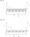
- inspection light L1 is applied to the bottom portion 3 having the recess 3a in which the granular substance Y is deposited. Then, the intensity of light L2 reflected from the bottom portion 3 is measured.
- Deposition of the granular substance Y in the recesses 3a reduces the intensity of light applied to the bottom portion 3 and reflected by the bottom portion 3. Accordingly, it is possible to improve the accuracy of measuring the concentration of the test substance.
- the inspection light L1 may be applied to the bottom portion 3, and the intensity of the light L2 reflected from the bottom portion 3 may be measured.
- a value of a difference between the reference light intensity and the evaluation light intensity is calculated.
- the relative value may be obtained using a value of a ratio between the reference light intensity and the evaluation light intensity.
- a value obtained by appropriately applying a mathematical operation to the difference or the ratio may be set as the relative value.
- the reflected light intensity may be measured only with a specific wavelength, and the reflected light intensity may be acquired as a spectrum at a plurality of consecutive wavelengths.
- any wavelength can be selected for a wavelength of light to be applied, the wavelength can be appropriately selected according to the shape and size of the periodic structure.
- visible light can be typically used, infrared or ultraviolet light can also be used.
- Fig. 10 is an enlarged front cross-sectional view for describing an example of the inspecting method using the implement for inspection according to the first embodiment of the present invention.
- the intensity of the light L2 reflected by the bottom portion 3 may be measured. Even in a state where the height at which the granular substance Y is deposited in the recess 3a does not reach the depth of the recess 3a (the height of the side surface of the recess 3a), the intensity of the light L2 reflected by the bottom portion 3 becomes low. Accordingly, the concentration of a low-concentration test substance can be measured. In addition, the inspection time can be shortened.
- a filling rate of the granular substance Y in the recess 3a at the time of measurement is preferably 1% or more, more preferably 10% or more, still more preferably 30% or more, even more preferably 50% or more, further more preferably 70% or more, particularly preferably 90% or more, most preferably 95% or more.
- the filling rate is the volume of the granular substance in the volume of the recess. When the granular substance is deposited between the protrusions, the volume of the granular substance in the volume between the protrusions is the filling rate.
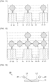
- Fig. 11 is an enlarged front cross-sectional view for describing an example of an inspecting method using the implement for inspection according to the fourth embodiment of the present invention.
- a test substance Z1 in this inspecting method is an antigen bound to the antibody 57 and the antibody possessed by the compound 56.
- the test substance Z1 is bound to the compound 56 contained in the liquid W.
- the compound 56 is a granular substance.
- the test substance 21 bound to the compound 56 is bound to the antibody 57 disposed at the protrusion of the periodic structure 3A and selectively deposited on the protrusion. Consequently, a refractive index of a portion irradiated with the inspection light changes greatly.
- the wavelength of the inspection light and the period of the periodic structure 33A are substantially equal to each other, and a peak of light reflected at the photonic band gap occurs.
- the intensity of the peak of the reflected light greatly changes due to the change in the refractive index.
- the concentration of a test substance having an extremely low concentration of approximate 100 pg/ml or less.
- an implement for inspection in which the above-described compound is disposed at a position distant from the periodic structure may be used.
- the test substances Z1 are bound to each other via the compound 56 as a granular substance to form an aggregate Z2.
- the granular substance thus aggregated is deposited in the periodic structure 33A.
- the refractive index of the portion irradiated with the inspection light changes greatly.
- the concentration of a low-concentration test substance can be measured.
- Fig. 13 is a schematic diagram of an inspecting device according to a fifth embodiment of the present invention.
- An inspecting device 20 includes the implement 11 for inspection of the third embodiment, a light source 28, and a measuring instrument 29.
- Light L1 is applied from the light source 28 to the bottom portion having the recesses of the implement 11 for inspection.
- the intensity of light L2 reflected by the bottom portion is measured by the measuring instrument 29.
- the inspecting device 20 can measure the concentration of a test substance with high accuracy by the above-described inspecting method.
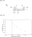
- Fig. 14 is a schematic diagram of an inspecting device according to a sixth embodiment of the present invention.
- An inspecting device 40 includes the implement 1 for inspection of the first embodiment, an installation portion 44 in which the implement 1 for inspection is installed, a light source 28, and a measuring instrument 29.
- the installation portion 44 has a flow path 47 through which a liquid containing a test substance is sent.
- the flow path 47 is connected to the introduction portion 7 of the implement 1 for inspection.
- a reaction between the test substance and a compound can be started by introducing the liquid containing the test substance into the storage portion of the implement 1 for inspection through the flow path 47.
- the concentration of the test substance can be measured with high accuracy by the above-described inspecting method. The inspection can be easily performed by installing the implement 1 for inspection in the installation portion 44.
- the above-described implement for inspection may be a microfluidic device, and the microfluidic device may include a compound capable of forming a granular substance or a compound which is capable of being bound to the test substance and is a granular substance, and a wall portion.
- the compound may be disposed in a microchannel in the microfluidic device.
- the wall portion may be an inner wall portion of the microchannel in the microfluidic device.
- the inspecting device may be a microfluidic device including the light source and the measuring instrument described above.
- the implement for inspection of the third embodiment was used to determine a relationship between the concentration of endotoxin and intensity of reflected light at the bottom portion of the implement for inspection.
- the implement for inspection of the third embodiment was prepared.
- the recess had a cylindrical shape, and had a diameter of 230 nm and a plane area (opening area) of 41.5 ⁇ 10 3 nm 2 .
- a distance between the recesses was 460 nm, and the depth of the recess was 200 nm.
- blank data reference light intensity
- the bottom portion of the implement for inspection was irradiated with light, and the intensity of light reflected by the bottom portion was measured, whereby the blank data was acquired.
- a liquid containing endotoxin and water was prepared.
- the endotoxin concentrations in the liquid containing endotoxin and water were 0.000625 EU/ml, 0.00125 EU/ml, 0.0025 EU/ml, 0.005 EU/ml, 0.01 EU/ml, 0.025 EU/ml, 0.05 EU/ml, and 0.1 EU/ml, respectively.
- LAL reagent manufactured by Lonza Ltd.
- LAL reagent manufactured by Lonza Ltd.
- the lid was disposed on the storage portion, and the implement for inspection was left to stand for 60 minutes.
- the liquid containing endotoxin and water was removed.
- the bottom portion of the implement for inspection was irradiated with light, and the intensity (evaluation light intensity) of light reflected by the bottom portion was measured.
- ⁇ intensity in each liquid containing endotoxin and water was determined.
- the ⁇ intensity is a difference between the intensity of the light reflected by the bottom portion and the blank data.
- the ⁇ intensity when water was stored in the storage portion was determined.
- Fig. 15 is a view showing a relationship between the endotoxin concentration and the ⁇ intensity in Example 1.
- Fig. 15 it is found that at the endotoxin concentration of 0.000625 EU/ml or more, the ⁇ intensity decreases as the endotoxin concentration increases.
- high-precision inspection can be performed at a concentration around 0.001 EU/ml, and that inspection can be performed even within a concentration range lower than 0.001 EU/ml.
- the relationship between the endotoxin concentration and the intensity of the reflected light at the bottom portion of the implement for inspection was determined in the same manner as in Example 1 except that LAL reagent (manufactured by Wako Pure Chem. Ind. Ltd.) was used as the above compound.
- Fig. 16 is a view showing a relationship between the endotoxin concentration and the ⁇ intensity in Example 2.
- the implement for inspection of the fourth embodiment was used to determine a relationship between the concentration of cystatin C and the intensity of the reflected light at the bottom portion of the implement for inspection.
- the implement for inspection of the fourth embodiment was prepared.
- the protrusion in the periodic structure had a cylindrical shape and had a diameter of 230 nm. A distance between the protrusions was 460 nm.
- the surface of the periodic structure was immersed in a cystatin C antibody aqueous solution for 24 hours. Then, washing with TBS-T buffer was performed three times. Then, the implement for inspection was dried. Thus, the periodic structure was modified with cystatin C antibody.
- cystatin C and physiological saline were prepared.
- the cystatin C concentrations in the liquid containing cystatin C and physiological saline were 0 pg/ml, 10 pg/ml and 100 pg/ml, respectively.
- a cystatin C antibody modified latex aqueous solution (manufactured by Sekisui Medical Co., Ltd.) was placed on the lid. Then, the cystatin C antibody modified latex aqueous solution was stored in the storage portion of the implement for inspection. Then, the reflected light intensity immediately after adding the liquid containing cystatin C and physiological saline (0 minutes) and the reflected light intensity after standing for 10 minutes were measured. The implement for inspection was irradiated with light at an angle of 15°, and the intensity (evaluation light intensity) of the reflected light was measured.
- d intensity in each liquid containing cystatin C and water was determined.
- the d intensity is a difference between the reflected light intensity immediately after adding a liquid (0 minutes) and the reflected light intensity after standing for 10 minutes.
- the ⁇ intensity when water was stored in the storage portion was determined.
- Fig. 17 is a view showing a relationship between the cystatin C concentration and the d intensity in Example 3.
- Fig. 18 is an SEM photograph (using trade name "VE-8800" manufactured by Keyence Corporation) of 10 pg/ml cystatin C in Example 3, and it is found that cystatin C antibody modified latex is adsorbed to the protrusions in the periodic structure.
Landscapes
- Health & Medical Sciences (AREA)
- Life Sciences & Earth Sciences (AREA)
- Chemical & Material Sciences (AREA)
- Immunology (AREA)
- Engineering & Computer Science (AREA)
- Physics & Mathematics (AREA)
- Analytical Chemistry (AREA)
- Biochemistry (AREA)
- General Health & Medical Sciences (AREA)
- General Physics & Mathematics (AREA)
- Pathology (AREA)
- Molecular Biology (AREA)
- Biomedical Technology (AREA)
- Hematology (AREA)
- Urology & Nephrology (AREA)
- Plasma & Fusion (AREA)
- Biotechnology (AREA)
- Cell Biology (AREA)
- Microbiology (AREA)
- Chemical Kinetics & Catalysis (AREA)
- Food Science & Technology (AREA)
- Medicinal Chemistry (AREA)
- Investigating Or Analysing Materials By Optical Means (AREA)
- Investigating Or Analysing Biological Materials (AREA)
Claims (7)
- Gerät zur Inspektion, verwendet zum Messen einer Konzentration einer Testsubstanz,wobei das Gerät (1, 11) zur Inspektion eine Verbindung (6) zum Reagieren mit der Testsubstanz zum Bilden einer granulären Substanz oder eine Verbindung, die zum Binden an die Testsubstanz vorgesehen ist und eine granuläre Substanz ist, umfasst; undwobei das Gerät (1, 11) zur Inspektion weiter einen Bodenabschnitt (3) mit einer periodischen Struktur (3A, 13A, 33A) auf einer Fläche des Bodenabschnitts (3) umfasst; einen Seitenwandabschnitt (4), der von dem Bodenabschnitt (3) ausgehend aufgerichtet ist; und einen Deckel (5), der auf der zu der Seite des Bodenabschnitts (3) des Seitenwandabschnitts (4) entgegengesetzten Seite angeordnet ist,wobei das Gerät (1, 11) zur Inspektion einen Speicherabschnitt (2) aufweist, bei dem es sich um das Volumen handelt, das von dem Bodenabschnitt (3) und dem Seitenwandabschnitt (4) und dem Deckel (5) umgeben ist,wobei der Deckel (5) auf dem Speicherabschnitt (2) angeordnet ist, wobei die periodische Struktur (3A, 13A, 33A) in dem Bodenabschnitt (3) eine Mehrzahl von Vertiefungen (3a, 13a, 33a) oder eine Mehrzahl von Vorsprüngen aufweist,wobei eine Periode der periodischen Struktur (3A, 13A, 33A) 1000 nm oder weniger beträgt, undwobei die Verbindung (6) nicht mit der periodischen Struktur (3A, 13A, 33A) in dem Bodenabschnitt (3) in Kontakt ist, an einer von der periodischen Struktur (3A, 13A, 33A) in dem Bodenabschnitt (3) entfernten Position angeordnet ist und auf dem Speicherabschnitt (2) angeordnet ist, in den eine Flüssigkeit, die die Testsubstanz enthält, eingeleitet werden kann, da die Verbindung (6) auf der Oberfläche des Deckels (5) angeordnet ist.
- Gerät (1, 11) zur Inspektion nach Anspruch 1, wobeiwenn das Gerät (1, 11) zur Inspektion die Verbindung (6) zum Reagieren mit der Testsubstanz zum Bilden der granulären Substanz aufweist, die Verbindung zum Reagieren mit der Testsubstanz zum Bilden der granulären Substanz eine Verbindung zum Reagieren mit der Testsubstanz zum Bilden einer granulären Substanz in einem aggregierten Zustand ist, undwenn das Gerät (1, 11) zur Inspektion die Verbindung (6), die zum Binden an die Testsubstanz vorgesehen ist und die granuläre Substanz ist, aufweist, die Verbindung, die zum Binden an die Testsubstanz vorgesehen ist und die granuläre Substanz ist, an die Testsubstanz gebunden wird, um eine granuläre Substanz in einem aggregierten Zustand zu bilden.
- Gerät (1, 11) zur Inspektion nach Anspruch 1 oder 2, wobei die Verbindung (6) zum Binden an die Testsubstanz vorgesehen ist und eine granuläre Substanz ist, wobeidie Testsubstanz ein Antigen aufweist, unddie Verbindung (6) einen Antikörper (57) aufweist.
- Gerät (1, 11) zur Inspektion nach Anspruch 1 oder 2, wobei die Verbindung (6) zum Reagieren mit der Testsubstanz zum Bilden einer granulären Substanz vorgesehen ist, wobeidie Testsubstanz ein Glykolipid ist, unddie Verbindung (6) ein Enzym zum Reagieren mit dem Glykolipid ist.
- Gerät (1, 11) zur Inspektion nach Anspruch 1 oder 2, wobei die Verbindung (6) zum Reagieren mit der Testsubstanz zum Bilden einer granulären Substanz vorgesehen ist, wobeidie Testsubstanz ein Endotoxin ist, unddie Verbindung (6) ein LAL-Reagenz ist.
- Inspektionsvorrichtung (20), umfassend:das Gerät (1) zur Inspektion nach einem der Ansprüche 1 bis 5;eine Lichtquelle (28) zum Aufbringen von Licht auf den Bodenabschnitt (3) mit der periodischen Struktur (3A, 13A, 33A) des Geräts (1, 11) zur Inspektion; undein Messgerät (29) zum Messen einer Intensität von Licht, das von der Lichtquelle emittiert und von dem Bodenabschnitt mit der periodischen Struktur (3A, 13A, 33A) reflektiert wird.
- Inspektionsverfahren unter Verwendung des Geräts (1, 11) zur Inspektion nach einem der Ansprüche 1 bis 5, wobei das Inspektionsverfahren umfasst:einen Schritt des Aufbringens von Licht auf die periodische Struktur (3A, 13A, 33A) zum Messen einer Intensität von Referenzlicht in einem Zustand, in dem die Testsubstanz nicht in das Gerät (1, 11) zur Inspektion eingeleitet ist;einen Schritt des Aufbringens von Licht auf die periodische Struktur (3A, 13A, 33A) zum Messen einer Intensität von Untersuchungslicht in einem Zustand, in dem die Testsubstanz in das Gerät (1, 11) zur Inspektion eingeleitet ist und die granuläre Substanz auf der periodischen Struktur (3A, 13A, 33A) abgelagert ist; undeinen Schritt des Erhaltens eines relativen Werts der Intensität des Referenzlichts und der Intensität des Untersuchungslichts, wobeiwenn der relative Wert, der erhalten wird, wenn eine Probe, in der eine Konzentration der Testsubstanz bekannt ist, in das Gerät (1, 11) zur Inspektion eingeleitet wird, mit dem relativen Wert verglichen wird, der erhalten wird, wenn eine Probe, in der eine Konzentration der Testsubstanz unbekannt ist, in das Gerät (1, 11) zur Inspektion eingeleitet wird, die Konzentration der Testsubstanz in der Probe bestimmt wird, in der die Konzentration der Testsubstanz unbekannt ist.
Applications Claiming Priority (2)
| Application Number | Priority Date | Filing Date | Title |
|---|---|---|---|
| JP2016022465 | 2016-02-09 | ||
| PCT/JP2017/004680 WO2017138595A1 (ja) | 2016-02-09 | 2017-02-09 | 検査用器具、検査装置及び検査方法 |
Publications (3)
| Publication Number | Publication Date |
|---|---|
| EP3415917A1 EP3415917A1 (de) | 2018-12-19 |
| EP3415917A4 EP3415917A4 (de) | 2019-09-11 |
| EP3415917B1 true EP3415917B1 (de) | 2025-01-15 |
Family
ID=59563117
Family Applications (1)
| Application Number | Title | Priority Date | Filing Date |
|---|---|---|---|
| EP17750316.6A Active EP3415917B1 (de) | 2016-02-09 | 2017-02-09 | Gerät zur inspektion, inspektionsvorrichtung und inspektionsverfahren |
Country Status (5)
| Country | Link |
|---|---|
| US (2) | US11016087B2 (de) |
| EP (1) | EP3415917B1 (de) |
| JP (1) | JP6328853B2 (de) |
| CN (1) | CN108713144B (de) |
| WO (1) | WO2017138595A1 (de) |
Families Citing this family (2)
| Publication number | Priority date | Publication date | Assignee | Title |
|---|---|---|---|---|
| JP7345782B2 (ja) * | 2018-07-31 | 2023-09-19 | 積水化学工業株式会社 | 検査方法、検査用器具及び検査装置 |
| WO2021193589A1 (ja) * | 2020-03-23 | 2021-09-30 | 積水化学工業株式会社 | 検査方法、検査キット及び検査システム |
Citations (1)
| Publication number | Priority date | Publication date | Assignee | Title |
|---|---|---|---|---|
| US20150268237A1 (en) * | 2014-03-24 | 2015-09-24 | Josef Kerimo | Bioassay system and method for detecting analytes in body fluids |
Family Cites Families (18)
| Publication number | Priority date | Publication date | Assignee | Title |
|---|---|---|---|---|
| JPS6033403Y2 (ja) | 1980-10-09 | 1985-10-04 | オリンパス光学工業株式会社 | プレ−ト型粒子凝集判定用容器 |
| JPS6086468A (ja) | 1983-10-18 | 1985-05-16 | Olympus Optical Co Ltd | 抗原抗体反応の判定方法 |
| JPH0643951B2 (ja) | 1986-04-30 | 1994-06-08 | リコ−精器株式会社 | 堆積物検出装置 |
| US6300141B1 (en) * | 1999-03-02 | 2001-10-09 | Helix Biopharma Corporation | Card-based biosensor device |
| JP3766575B2 (ja) * | 2000-01-18 | 2006-04-12 | オリンパス株式会社 | 反応性微粒子を用いた分析方法および分析用容器 |
| US7070987B2 (en) | 2000-10-30 | 2006-07-04 | Sru Biosystems, Inc. | Guided mode resonant filter biosensor using a linear grating surface structure |
| US20040002121A1 (en) * | 2001-11-06 | 2004-01-01 | Regan Jeffrey F. | High throughput methods and devices for assaying analytes in a fluid sample |
| MX383382B (es) | 2005-12-21 | 2025-03-13 | Meso Scale Technologies Llc | Modulos de ensayo que tienen reactivos de ensayo y metodos para hacer y utilizar los mismos |
| JP2007327946A (ja) | 2006-05-09 | 2007-12-20 | Tokyo Univ Of Agriculture & Technology | 標的酵素の活性を測定する方法、標的酵素の活性を測定するためのキット、および標的酵素の活性を測定するためのバイオセンサ |
| JP2008002948A (ja) | 2006-06-22 | 2008-01-10 | Olympus Corp | 標的核酸の検出方法及び該検出方法に用いる容器 |
| JP5223125B2 (ja) | 2006-08-25 | 2013-06-26 | 謙治 佐藤 | 無線タグ型センサ |
| US20100046902A1 (en) * | 2006-11-03 | 2010-02-25 | Trustees Of Tufts College | Biopolymer photonic crystals and method of manufacturing the same |
| US7737392B2 (en) * | 2006-11-09 | 2010-06-15 | The Board Of Trustees Of The University Of Illinois | Photonic crystal sensors with integrated fluid containment structure, sample handling devices incorporating same, and uses thereof for biomolecular interaction analysis |
| JP5188311B2 (ja) | 2008-07-30 | 2013-04-24 | 興和株式会社 | 生物由来の生理活性物質の測定方法及び測定装置 |
| CN101825629B (zh) | 2009-03-06 | 2014-03-26 | 北京工业大学 | 波导耦合金属光子晶体生物传感器及其检测方法 |
| JP5014466B2 (ja) | 2010-06-04 | 2012-08-29 | 徹 小幡 | ゲル粒子測定装置 |
| JP2012098272A (ja) | 2010-08-23 | 2012-05-24 | Nsk Ltd | 標的物質濃度測定装置および標的物質濃度測定方法 |
| CN104220862B (zh) | 2013-04-12 | 2018-02-09 | 日本精工株式会社 | 靶物质捕捉装置 |
-
2017
- 2017-02-09 WO PCT/JP2017/004680 patent/WO2017138595A1/ja not_active Ceased
- 2017-02-09 JP JP2017526713A patent/JP6328853B2/ja active Active
- 2017-02-09 CN CN201780010615.4A patent/CN108713144B/zh active Active
- 2017-02-09 EP EP17750316.6A patent/EP3415917B1/de active Active
- 2017-02-09 US US16/076,637 patent/US11016087B2/en active Active
-
2021
- 2021-04-22 US US17/237,917 patent/US20210239690A1/en active Pending
Patent Citations (1)
| Publication number | Priority date | Publication date | Assignee | Title |
|---|---|---|---|---|
| US20150268237A1 (en) * | 2014-03-24 | 2015-09-24 | Josef Kerimo | Bioassay system and method for detecting analytes in body fluids |
Also Published As
| Publication number | Publication date |
|---|---|
| EP3415917A1 (de) | 2018-12-19 |
| US20190041337A1 (en) | 2019-02-07 |
| US20210239690A1 (en) | 2021-08-05 |
| JPWO2017138595A1 (ja) | 2018-02-15 |
| WO2017138595A1 (ja) | 2017-08-17 |
| CN108713144A (zh) | 2018-10-26 |
| EP3415917A4 (de) | 2019-09-11 |
| US11016087B2 (en) | 2021-05-25 |
| JP6328853B2 (ja) | 2018-05-23 |
| CN108713144B (zh) | 2021-08-13 |
Similar Documents
| Publication | Publication Date | Title |
|---|---|---|
| Liu et al. | Cancer diagnosis using label-free SERS-based exosome analysis | |
| Usman et al. | Plasmonic biosensors for the detection of lung cancer biomarkers: a review | |
| US8940523B2 (en) | Pipette tip, pipette system and method for performing analysis with the pipette tip and system | |
| CN100516835C (zh) | 局域等离子共振传感器和检查装置 | |
| US9678014B2 (en) | Capillary flow plasmonic sensor | |
| KR101328190B1 (ko) | 국소 표면플라즈몬 공명현상을 이용한 시료분석을 위한 카트리지 및 이를 이용한 분석방법 | |
| KR20140043806A (ko) | 나노구조를 가지는 표면 플라스몬 공명(spr) 센서 장치 | |
| US20210239690A1 (en) | Implement for inspection, inspecting device and inspecting method | |
| Li et al. | Molecular stratification and treatment monitoring of lung cancer using a small extracellular vesicle-activated nanocavity architecture | |
| JP6098523B2 (ja) | Spfs測定用センサーチップ、およびspfs測定用センサーチップを用いたspfs測定方法、ならびにspfs測定用センサーチップを備えたspfs測定装置 | |
| EP3832292B1 (de) | Inspektionsverfahren, inspektionsinstrument und inspektionsvorrichtung | |
| CN102762971A (zh) | 纳米流体生物传感器及其对于快速测量溶液中的生物分子相互作用的应用及方法 | |
| EP3314261B1 (de) | Schneller und hochempfindlicher bakteriennachweis | |
| US20110058165A1 (en) | Sample cell for spectrometric analysis and method of use | |
| EP3021968B1 (de) | Verfahren und vorrichtung für bioassays | |
| US20240402164A1 (en) | Plasmonic caged nanoplatforms and methods thereof | |
| WO2021193589A1 (ja) | 検査方法、検査キット及び検査システム | |
| Hughes | Biosensing on the End of an Optical Fiber | |
| Terao et al. | Size-exclusion SPR sensor chip: application to detection of aggregation and disaggregation of biological particles | |
| Wen | Development of Novel Diagnostic Platforms Using Gold Nanoparticles and Spectroscopy | |
| US9739718B2 (en) | Flow-valve diagnostic microfluidic system | |
| Hughes et al. | Fiberoptic nanobiosensor: A quantitative calibration method |
Legal Events
| Date | Code | Title | Description |
|---|---|---|---|
| STAA | Information on the status of an ep patent application or granted ep patent |
Free format text: STATUS: THE INTERNATIONAL PUBLICATION HAS BEEN MADE |
|
| PUAI | Public reference made under article 153(3) epc to a published international application that has entered the european phase |
Free format text: ORIGINAL CODE: 0009012 |
|
| STAA | Information on the status of an ep patent application or granted ep patent |
Free format text: STATUS: REQUEST FOR EXAMINATION WAS MADE |
|
| 17P | Request for examination filed |
Effective date: 20180807 |
|
| AK | Designated contracting states |
Kind code of ref document: A1 Designated state(s): AL AT BE BG CH CY CZ DE DK EE ES FI FR GB GR HR HU IE IS IT LI LT LU LV MC MK MT NL NO PL PT RO RS SE SI SK SM TR |
|
| AX | Request for extension of the european patent |
Extension state: BA ME |
|
| DAV | Request for validation of the european patent (deleted) | ||
| DAX | Request for extension of the european patent (deleted) | ||
| A4 | Supplementary search report drawn up and despatched |
Effective date: 20190808 |
|
| RIC1 | Information provided on ipc code assigned before grant |
Ipc: G01N 33/579 20060101ALI20190802BHEP Ipc: G01N 21/82 20060101AFI20190802BHEP Ipc: G01N 21/47 20060101ALI20190802BHEP |
|
| STAA | Information on the status of an ep patent application or granted ep patent |
Free format text: STATUS: EXAMINATION IS IN PROGRESS |
|
| 17Q | First examination report despatched |
Effective date: 20220421 |
|
| GRAP | Despatch of communication of intention to grant a patent |
Free format text: ORIGINAL CODE: EPIDOSNIGR1 |
|
| STAA | Information on the status of an ep patent application or granted ep patent |
Free format text: STATUS: GRANT OF PATENT IS INTENDED |
|
| INTG | Intention to grant announced |
Effective date: 20240812 |
|
| GRAS | Grant fee paid |
Free format text: ORIGINAL CODE: EPIDOSNIGR3 |
|
| GRAA | (expected) grant |
Free format text: ORIGINAL CODE: 0009210 |
|
| STAA | Information on the status of an ep patent application or granted ep patent |
Free format text: STATUS: THE PATENT HAS BEEN GRANTED |
|
| AK | Designated contracting states |
Kind code of ref document: B1 Designated state(s): AL AT BE BG CH CY CZ DE DK EE ES FI FR GB GR HR HU IE IS IT LI LT LU LV MC MK MT NL NO PL PT RO RS SE SI SK SM TR |
|
| REG | Reference to a national code |
Ref country code: CH Ref legal event code: EP Ref country code: GB Ref legal event code: FG4D |
|
| P01 | Opt-out of the competence of the unified patent court (upc) registered |
Free format text: CASE NUMBER: APP_65909/2024 Effective date: 20241213 |
|
| REG | Reference to a national code |
Ref country code: DE Ref legal event code: R096 Ref document number: 602017087347 Country of ref document: DE |
|
| REG | Reference to a national code |
Ref country code: IE Ref legal event code: FG4D |
|
| PGFP | Annual fee paid to national office [announced via postgrant information from national office to epo] |
Ref country code: DE Payment date: 20250226 Year of fee payment: 9 |
|
| REG | Reference to a national code |
Ref country code: NL Ref legal event code: MP Effective date: 20250115 |
|
| PG25 | Lapsed in a contracting state [announced via postgrant information from national office to epo] |
Ref country code: NL Free format text: LAPSE BECAUSE OF FAILURE TO SUBMIT A TRANSLATION OF THE DESCRIPTION OR TO PAY THE FEE WITHIN THE PRESCRIBED TIME-LIMIT Effective date: 20250115 |
|
| PG25 | Lapsed in a contracting state [announced via postgrant information from national office to epo] |
Ref country code: RS Free format text: LAPSE BECAUSE OF FAILURE TO SUBMIT A TRANSLATION OF THE DESCRIPTION OR TO PAY THE FEE WITHIN THE PRESCRIBED TIME-LIMIT Effective date: 20250415 |
|
| PG25 | Lapsed in a contracting state [announced via postgrant information from national office to epo] |
Ref country code: FI Free format text: LAPSE BECAUSE OF FAILURE TO SUBMIT A TRANSLATION OF THE DESCRIPTION OR TO PAY THE FEE WITHIN THE PRESCRIBED TIME-LIMIT Effective date: 20250115 |
|
| PG25 | Lapsed in a contracting state [announced via postgrant information from national office to epo] |
Ref country code: PL Free format text: LAPSE BECAUSE OF FAILURE TO SUBMIT A TRANSLATION OF THE DESCRIPTION OR TO PAY THE FEE WITHIN THE PRESCRIBED TIME-LIMIT Effective date: 20250115 |
|
| PG25 | Lapsed in a contracting state [announced via postgrant information from national office to epo] |
Ref country code: ES Free format text: LAPSE BECAUSE OF FAILURE TO SUBMIT A TRANSLATION OF THE DESCRIPTION OR TO PAY THE FEE WITHIN THE PRESCRIBED TIME-LIMIT Effective date: 20250115 |
|
| REG | Reference to a national code |
Ref country code: LT Ref legal event code: MG9D |
|
| PG25 | Lapsed in a contracting state [announced via postgrant information from national office to epo] |
Ref country code: NO Free format text: LAPSE BECAUSE OF FAILURE TO SUBMIT A TRANSLATION OF THE DESCRIPTION OR TO PAY THE FEE WITHIN THE PRESCRIBED TIME-LIMIT Effective date: 20250415 Ref country code: IS Free format text: LAPSE BECAUSE OF FAILURE TO SUBMIT A TRANSLATION OF THE DESCRIPTION OR TO PAY THE FEE WITHIN THE PRESCRIBED TIME-LIMIT Effective date: 20250515 |
|
| REG | Reference to a national code |
Ref country code: AT Ref legal event code: MK05 Ref document number: 1760126 Country of ref document: AT Kind code of ref document: T Effective date: 20250115 |
|
| PG25 | Lapsed in a contracting state [announced via postgrant information from national office to epo] |
Ref country code: HR Free format text: LAPSE BECAUSE OF FAILURE TO SUBMIT A TRANSLATION OF THE DESCRIPTION OR TO PAY THE FEE WITHIN THE PRESCRIBED TIME-LIMIT Effective date: 20250115 |
|
| PG25 | Lapsed in a contracting state [announced via postgrant information from national office to epo] |
Ref country code: LV Free format text: LAPSE BECAUSE OF FAILURE TO SUBMIT A TRANSLATION OF THE DESCRIPTION OR TO PAY THE FEE WITHIN THE PRESCRIBED TIME-LIMIT Effective date: 20250115 Ref country code: PT Free format text: LAPSE BECAUSE OF FAILURE TO SUBMIT A TRANSLATION OF THE DESCRIPTION OR TO PAY THE FEE WITHIN THE PRESCRIBED TIME-LIMIT Effective date: 20250515 |
|
| PG25 | Lapsed in a contracting state [announced via postgrant information from national office to epo] |
Ref country code: BG Free format text: LAPSE BECAUSE OF FAILURE TO SUBMIT A TRANSLATION OF THE DESCRIPTION OR TO PAY THE FEE WITHIN THE PRESCRIBED TIME-LIMIT Effective date: 20250115 Ref country code: GR Free format text: LAPSE BECAUSE OF FAILURE TO SUBMIT A TRANSLATION OF THE DESCRIPTION OR TO PAY THE FEE WITHIN THE PRESCRIBED TIME-LIMIT Effective date: 20250416 |
|
| PG25 | Lapsed in a contracting state [announced via postgrant information from national office to epo] |
Ref country code: AT Free format text: LAPSE BECAUSE OF FAILURE TO SUBMIT A TRANSLATION OF THE DESCRIPTION OR TO PAY THE FEE WITHIN THE PRESCRIBED TIME-LIMIT Effective date: 20250115 |
|
| PG25 | Lapsed in a contracting state [announced via postgrant information from national office to epo] |
Ref country code: SE Free format text: LAPSE BECAUSE OF FAILURE TO SUBMIT A TRANSLATION OF THE DESCRIPTION OR TO PAY THE FEE WITHIN THE PRESCRIBED TIME-LIMIT Effective date: 20250115 |
|
| REG | Reference to a national code |
Ref country code: CH Ref legal event code: PL |
|
| PG25 | Lapsed in a contracting state [announced via postgrant information from national office to epo] |
Ref country code: SM Free format text: LAPSE BECAUSE OF FAILURE TO SUBMIT A TRANSLATION OF THE DESCRIPTION OR TO PAY THE FEE WITHIN THE PRESCRIBED TIME-LIMIT Effective date: 20250115 |
|
| PG25 | Lapsed in a contracting state [announced via postgrant information from national office to epo] |
Ref country code: DK Free format text: LAPSE BECAUSE OF FAILURE TO SUBMIT A TRANSLATION OF THE DESCRIPTION OR TO PAY THE FEE WITHIN THE PRESCRIBED TIME-LIMIT Effective date: 20250115 |
|
| PG25 | Lapsed in a contracting state [announced via postgrant information from national office to epo] |
Ref country code: MC Free format text: LAPSE BECAUSE OF FAILURE TO SUBMIT A TRANSLATION OF THE DESCRIPTION OR TO PAY THE FEE WITHIN THE PRESCRIBED TIME-LIMIT Effective date: 20250115 |
|
| PG25 | Lapsed in a contracting state [announced via postgrant information from national office to epo] |
Ref country code: LU Free format text: LAPSE BECAUSE OF NON-PAYMENT OF DUE FEES Effective date: 20250209 Ref country code: IT Free format text: LAPSE BECAUSE OF FAILURE TO SUBMIT A TRANSLATION OF THE DESCRIPTION OR TO PAY THE FEE WITHIN THE PRESCRIBED TIME-LIMIT Effective date: 20250115 |
|
| REG | Reference to a national code |
Ref country code: DE Ref legal event code: R097 Ref document number: 602017087347 Country of ref document: DE |
|
| PG25 | Lapsed in a contracting state [announced via postgrant information from national office to epo] |
Ref country code: CH Free format text: LAPSE BECAUSE OF NON-PAYMENT OF DUE FEES Effective date: 20250228 |
|
| PG25 | Lapsed in a contracting state [announced via postgrant information from national office to epo] |
Ref country code: EE Free format text: LAPSE BECAUSE OF FAILURE TO SUBMIT A TRANSLATION OF THE DESCRIPTION OR TO PAY THE FEE WITHIN THE PRESCRIBED TIME-LIMIT Effective date: 20250115 Ref country code: CZ Free format text: LAPSE BECAUSE OF FAILURE TO SUBMIT A TRANSLATION OF THE DESCRIPTION OR TO PAY THE FEE WITHIN THE PRESCRIBED TIME-LIMIT Effective date: 20250115 |
|
| PG25 | Lapsed in a contracting state [announced via postgrant information from national office to epo] |
Ref country code: RO Free format text: LAPSE BECAUSE OF FAILURE TO SUBMIT A TRANSLATION OF THE DESCRIPTION OR TO PAY THE FEE WITHIN THE PRESCRIBED TIME-LIMIT Effective date: 20250115 |
|
| PG25 | Lapsed in a contracting state [announced via postgrant information from national office to epo] |
Ref country code: SK Free format text: LAPSE BECAUSE OF FAILURE TO SUBMIT A TRANSLATION OF THE DESCRIPTION OR TO PAY THE FEE WITHIN THE PRESCRIBED TIME-LIMIT Effective date: 20250115 |
|
| PLBE | No opposition filed within time limit |
Free format text: ORIGINAL CODE: 0009261 |
|
| STAA | Information on the status of an ep patent application or granted ep patent |
Free format text: STATUS: NO OPPOSITION FILED WITHIN TIME LIMIT |
|
| REG | Reference to a national code |
Ref country code: BE Ref legal event code: MM Effective date: 20250228 |
|
| 26N | No opposition filed |
Effective date: 20251016 |
|
| GBPC | Gb: european patent ceased through non-payment of renewal fee |
Effective date: 20250415 |
|
| PG25 | Lapsed in a contracting state [announced via postgrant information from national office to epo] |
Ref country code: GB Free format text: LAPSE BECAUSE OF NON-PAYMENT OF DUE FEES Effective date: 20250415 |
|
| PG25 | Lapsed in a contracting state [announced via postgrant information from national office to epo] |
Ref country code: FR Free format text: LAPSE BECAUSE OF NON-PAYMENT OF DUE FEES Effective date: 20250315 |
|
| PG25 | Lapsed in a contracting state [announced via postgrant information from national office to epo] |
Ref country code: BE Free format text: LAPSE BECAUSE OF NON-PAYMENT OF DUE FEES Effective date: 20250228 |
|
| PG25 | Lapsed in a contracting state [announced via postgrant information from national office to epo] |
Ref country code: IE Free format text: LAPSE BECAUSE OF NON-PAYMENT OF DUE FEES Effective date: 20250209 |