EP3410052B1 - Verkohlungsvorrichtung - Google Patents
Verkohlungsvorrichtung Download PDFInfo
- Publication number
- EP3410052B1 EP3410052B1 EP18174738.7A EP18174738A EP3410052B1 EP 3410052 B1 EP3410052 B1 EP 3410052B1 EP 18174738 A EP18174738 A EP 18174738A EP 3410052 B1 EP3410052 B1 EP 3410052B1
- Authority
- EP
- European Patent Office
- Prior art keywords
- target material
- treatment target
- furnace body
- stirring
- axis direction
- Prior art date
- Legal status (The legal status is an assumption and is not a legal conclusion. Google has not performed a legal analysis and makes no representation as to the accuracy of the status listed.)
- Active
Links
Images



Classifications
-
- F—MECHANICAL ENGINEERING; LIGHTING; HEATING; WEAPONS; BLASTING
- F27—FURNACES; KILNS; OVENS; RETORTS
- F27B—FURNACES, KILNS, OVENS OR RETORTS IN GENERAL; OPEN SINTERING OR LIKE APPARATUS
- F27B7/00—Rotary-drum furnaces, i.e. horizontal or slightly inclined
- F27B7/14—Rotary-drum furnaces, i.e. horizontal or slightly inclined with means for agitating or moving the charge
- F27B7/16—Rotary-drum furnaces, i.e. horizontal or slightly inclined with means for agitating or moving the charge the means being fixed relatively to the drum, e.g. composite means
-
- C—CHEMISTRY; METALLURGY
- C10—PETROLEUM, GAS OR COKE INDUSTRIES; TECHNICAL GASES CONTAINING CARBON MONOXIDE; FUELS; LUBRICANTS; PEAT
- C10B—DESTRUCTIVE DISTILLATION OF CARBONACEOUS MATERIALS FOR PRODUCTION OF GAS, COKE, TAR, OR SIMILAR MATERIALS
- C10B53/00—Destructive distillation, specially adapted for particular solid raw materials or solid raw materials in special form
-
- C—CHEMISTRY; METALLURGY
- C10—PETROLEUM, GAS OR COKE INDUSTRIES; TECHNICAL GASES CONTAINING CARBON MONOXIDE; FUELS; LUBRICANTS; PEAT
- C10B—DESTRUCTIVE DISTILLATION OF CARBONACEOUS MATERIALS FOR PRODUCTION OF GAS, COKE, TAR, OR SIMILAR MATERIALS
- C10B33/00—Discharging devices; Coke guides
-
- C—CHEMISTRY; METALLURGY
- C10—PETROLEUM, GAS OR COKE INDUSTRIES; TECHNICAL GASES CONTAINING CARBON MONOXIDE; FUELS; LUBRICANTS; PEAT
- C10B—DESTRUCTIVE DISTILLATION OF CARBONACEOUS MATERIALS FOR PRODUCTION OF GAS, COKE, TAR, OR SIMILAR MATERIALS
- C10B47/00—Destructive distillation of solid carbonaceous materials with indirect heating, e.g. by external combustion
-
- C—CHEMISTRY; METALLURGY
- C10—PETROLEUM, GAS OR COKE INDUSTRIES; TECHNICAL GASES CONTAINING CARBON MONOXIDE; FUELS; LUBRICANTS; PEAT
- C10B—DESTRUCTIVE DISTILLATION OF CARBONACEOUS MATERIALS FOR PRODUCTION OF GAS, COKE, TAR, OR SIMILAR MATERIALS
- C10B47/00—Destructive distillation of solid carbonaceous materials with indirect heating, e.g. by external combustion
- C10B47/28—Other processes
- C10B47/30—Other processes in rotary ovens or retorts
-
- C—CHEMISTRY; METALLURGY
- C10—PETROLEUM, GAS OR COKE INDUSTRIES; TECHNICAL GASES CONTAINING CARBON MONOXIDE; FUELS; LUBRICANTS; PEAT
- C10B—DESTRUCTIVE DISTILLATION OF CARBONACEOUS MATERIALS FOR PRODUCTION OF GAS, COKE, TAR, OR SIMILAR MATERIALS
- C10B53/00—Destructive distillation, specially adapted for particular solid raw materials or solid raw materials in special form
- C10B53/02—Destructive distillation, specially adapted for particular solid raw materials or solid raw materials in special form of cellulose-containing material
-
- F—MECHANICAL ENGINEERING; LIGHTING; HEATING; WEAPONS; BLASTING
- F27—FURNACES; KILNS; OVENS; RETORTS
- F27B—FURNACES, KILNS, OVENS OR RETORTS IN GENERAL; OPEN SINTERING OR LIKE APPARATUS
- F27B7/00—Rotary-drum furnaces, i.e. horizontal or slightly inclined
- F27B7/14—Rotary-drum furnaces, i.e. horizontal or slightly inclined with means for agitating or moving the charge
- F27B7/16—Rotary-drum furnaces, i.e. horizontal or slightly inclined with means for agitating or moving the charge the means being fixed relatively to the drum, e.g. composite means
- F27B7/161—Rotary-drum furnaces, i.e. horizontal or slightly inclined with means for agitating or moving the charge the means being fixed relatively to the drum, e.g. composite means the means comprising projections jutting out from the wall
-
- F—MECHANICAL ENGINEERING; LIGHTING; HEATING; WEAPONS; BLASTING
- F27—FURNACES; KILNS; OVENS; RETORTS
- F27B—FURNACES, KILNS, OVENS OR RETORTS IN GENERAL; OPEN SINTERING OR LIKE APPARATUS
- F27B7/00—Rotary-drum furnaces, i.e. horizontal or slightly inclined
- F27B7/14—Rotary-drum furnaces, i.e. horizontal or slightly inclined with means for agitating or moving the charge
- F27B7/16—Rotary-drum furnaces, i.e. horizontal or slightly inclined with means for agitating or moving the charge the means being fixed relatively to the drum, e.g. composite means
- F27B7/161—Rotary-drum furnaces, i.e. horizontal or slightly inclined with means for agitating or moving the charge the means being fixed relatively to the drum, e.g. composite means the means comprising projections jutting out from the wall
- F27B7/162—Rotary-drum furnaces, i.e. horizontal or slightly inclined with means for agitating or moving the charge the means being fixed relatively to the drum, e.g. composite means the means comprising projections jutting out from the wall the projections consisting of separate lifting elements, e.g. lifting shovels
-
- Y—GENERAL TAGGING OF NEW TECHNOLOGICAL DEVELOPMENTS; GENERAL TAGGING OF CROSS-SECTIONAL TECHNOLOGIES SPANNING OVER SEVERAL SECTIONS OF THE IPC; TECHNICAL SUBJECTS COVERED BY FORMER USPC CROSS-REFERENCE ART COLLECTIONS [XRACs] AND DIGESTS
- Y02—TECHNOLOGIES OR APPLICATIONS FOR MITIGATION OR ADAPTATION AGAINST CLIMATE CHANGE
- Y02E—REDUCTION OF GREENHOUSE GAS [GHG] EMISSIONS, RELATED TO ENERGY GENERATION, TRANSMISSION OR DISTRIBUTION
- Y02E50/00—Technologies for the production of fuel of non-fossil origin
- Y02E50/10—Biofuels, e.g. bio-diesel
Definitions
- the present invention relates to a carbonization apparatus.
- a carbonization system of organic wastes in accordance with material properties and use of a carbonized material, known are methods such as a fixed bed type one which is batch type and requires less installation area, a moving bed type one which is continuous type and requires shorter treatment time, an internal heating type one which accompanies combustion of a material, an external heating type one which indirectly heats a material, and the like.
- an external heating moving bed furnace in order to carbonize a material on continuous and stable heating conditions and manufacture a carbonized material as a phosphorus fertilizer material with high solubility, an external heating moving bed furnace is suitable.
- an external heating rotary kiln is most suitable.
- Japanese Patent Application Laid-Open Nos. 2008-122043 discloses a rotary kiln provided with a plurality of lifters in an axis direction of the kiln body.
- the tilt angle of the lifter is different in accordance with a position in the axis direction, it is possible to change a movement speed of a treatment target material and adjust a layer thickness to a desired one for each position.
- a heating zone through which hot air passes is formed between an inner cylinder and an outer cylinder. Then, by providing a spiral lifter on an outer peripheral surface of the inner cylinder, dust deposited in the heating zone is raked up toward a discharge port.
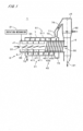
- the carbonization furnace 2 includes a furnace body 3, a rotation mechanism 21, a stirring part 41, a discharge feed part 42, and an outer surface guide part 51.
- the furnace body 3 has a cylindrical shape around a first central axis J1 and formed of, for example, a metal material (including an alloy. The same applies to the following).
- a cross section of the furnace body 3 perpendicular to the first central axis J1 has a circular form. Only if the shape thereof can be regarded as almost circular, the cross section may have a polygon or the like.
- the furnace body 3 is rotated about the first central axis J1 by the rotation mechanism 21.
- the stirring part 41 and the discharge feed part 42 are each formed of, for example, a metal material, and are provided on the inner surface 33 of the furnace body 3.
- the stirring part 41 is provided in an area on the side of the charge port 31 in the axis direction, i.e., an area 331 away from the discharge port 32 (hereinafter, referred to as a "stirring area 331").
- the discharge feed part 42 is provided in an area on the side of the discharge port 32 in the axis direction, i.e., an area 332 between the stirring area 331 and the discharge port 32 (hereinafter, referred to as a "discharge feed area 332").
- the discharge feed part 42 includes a screw blade 421 and a plurality of auxiliary stirring parts 422.
- the screw blade 421 is a continuous blade provided in a spiral manner. Paying attention to the circumferential direction about the first central axis 11, the screw blade 421 is provided continuously along an entire circumference in the circumferential direction. Further, paying attention to the axis direction, the screw blade 421 is provided entirely in the discharge feed area 332. Similarly to the stirring blade 411, the screw blade 421 is also fixed perpendicular to or substantially perpendicular to the inner surface 33 of the furnace body 3. In the screw blade 421, the tilt angle at a portion in contact with the inner surface 33 of the furnace body 3 with respect to the axis direction is constant across the whole. In Fig. 2 , the tilt angle of the screw blade 421 is represented by reference sign ⁇ 2. As described later, the screw blade 421 may be provided intermittently along the entire circumference in the circumferential direction.
- the screw blade 421 is a feed blade.
- a clearance between the portions of the screw blade 421 which are adjacent to each other in the axis direction is continuous in a spiral manner as a conveyance path, and the treatment target material is carried through the conveyance path.
- the tilt angle of the screw blade 421 is larger than that of each of the plurality of stirring blades 411.
- the tilt angle of the screw blade 421 is larger than 45 degrees, and preferably larger than 60 degrees.
- the tilt angle of the screw blade 421 is smaller than 90 degrees.
- Fig. 3 is a view showing part of a cross section of the furnace body 3 perpendicular to the first central axis J1.
- the height H1 of the screw blade 421 perpendicular to the inner surface 33 is, for example, not smaller than 0.1 times the radius of the furnace body 3 and not larger than 0.3 times the radius.
- the height H1 of the screw blade 421 is preferably larger than a thickness of a layer 9 of the treatment target material (a thickness at the lowest portion of the furnace body 3), which is indicated by parallel hatch lines in Fig. 3 , and is not larger than, for example, twice the thickness of the layer 9.
- auxiliary stirring part group a group of auxiliary stirring parts 422 aligned in the axis direction is regarded as an auxiliary stirring part group, and a plurality of auxiliary stirring part groups are arranged at regular intervals in the circumferential direction.
- the number of auxiliary stirring part groups is, for example, two to four, but may be one.
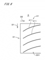
- Fig. 4 is a development view showing an outer surface (outer side surface) 34 of the furnace body 3, and Fig. 5 is a view showing an appearance of the furnace body 3.
- the upper side is the rotation direction front side and the lower side is the rotation direction rear side.
- the outer surface 34 of the furnace body 3 except both ends in the axis direction is covered with the external heating furnace 7.
- both ends of the external heating furnace 7 in the axis direction are indicated by two-dot chain lines.
- the outer surface guide blade 511 is fixed perpendicular to or substantially perpendicular to the outer surface 34.
- the tilt angle at a portion in contact with the outer surface 34 with respect to the axis direction is constant.
- the tilt angle of the outer surface guide blade 511 may be determined arbitrarily. Paying attention to parts of the outer surface guide blade 511, a portion on the feed direction rear side is positioned on the rotation direction front side as compared with a portion on the feed direction front side. Therefore, with the rotation of the furnace body 3, dust in the external heating furnace 7 described later is transported toward the feed direction front side by the outer surface guide blade 511.
- the combustion furnace 6 is provided with a supply nozzle 62.
- the supply nozzle 62 is disposed above the discharge port 32 and jets combustion air into the combustion furnace 6.
- the combustion air carries out complete combustion of the pyrolysis gas supplied from the carbonization furnace 2 and decomposes a harmful component to thereby generate a high-temperature combustion gas.
- One end of a hot air duct 79 is attached to an upper portion of the combustion furnace 6 and the combustion gas is discharged from the combustion furnace 6 through the hot air duct 79.
- a plurality of supply nozzles 62 may be provided along the circumferential direction.
- the combustion air and the pyrolysis gas can be thereby more uniformly mixed.
- a plurality of supply nozzle 62 may be provided along the second central axis J2.
- the supply nozzles 62 are provided thus in the direction of the second central axis J2 at a plurality of stages, it becomes possible to carry out combustion of the pyrolysis gas in stages (for example, two-stage combustion). As a result, it is possible to cope with the problem that nitrogen oxide is more easily generated by the high-temperature combustion.
- the treatment target material is charged into the furnace body 3 from the charge port 31.
- the treatment target material becomes likely to adhere to the inner surface 33 of the furnace body 3 in the vicinity of the charge port 31. If the treatment target material adheres to the inner surface 33, the efficiency of heat transfer is deteriorated. Therefore, in a preferable carbonization apparatus 1, as shown in Fig. 2 , the tilt angle of the stirring blades 411 disposed on the rearest side in the feed direction is made larger and the feed speed of the treatment target material in the vicinity of the charge port 31 is made higher. It is thereby possible to suppress adhesion of the treatment target material to the inner surface 33.
- the tilt angle of the stirring blades 411 disposed in the vicinity of the charge port 31 is not smaller than 20 degrees and not larger than 45 degrees.
- the carbonization apparatus 1 by changing the speed of the rotation of the furnace body 3 by the rotation mechanism 21, it is possible to adjust the retention time of the treatment target material in accordance with heating characteristics of the treatment target material. Furthermore, though the height H1 of the screw blade 421 is constant in the furnace body 3 of the present preferred embodiment, the height H1 of the screw blade 421 may be lowered continuously or in stages toward the feed direction front side in accordance with a proceeding of the carbonization in the carbonization area, i.e., a volume reduction of the treatment target material.
- the treatment target material retained on the front side of the rotation direction D1 in the layer 9 is carried back to the rear side of the rotation direction D1 while sliding on an upper surface of the layer 9 as shown by an arrow B2 of a thick broken line.
- the treatment target material is carried toward the feed direction front side along the screw blade 421 (along the already-described conveyance path), keeping a state in which the treatment target material is almost in contact with the inner surface 33 at the lowest portion of the furnace body 3.
- the combustion furnace 6 and the carbonization furnace 2 have an integral structure, it is possible to prevent the reduction in the calorific value of the pyrolysis gas, the blockage of the duct, and the like. Further, size reduction of the carbonization apparatus 1 can be ensured.
- a start-up operation for increasing the temperature of the furnace body 3 to a predetermined temperature is performed before charging the treatment target material into the furnace body 3.
- predetermined auxiliary fuel is used, but in a normal operation after the start-up operation (after the start of charging the treatment target material), the pyrolysis gas generated from the treatment target material can be used as the whole or part of the heat source for heating the furnace body 3.
Landscapes
- Chemical & Material Sciences (AREA)
- Engineering & Computer Science (AREA)
- Oil, Petroleum & Natural Gas (AREA)
- Materials Engineering (AREA)
- Organic Chemistry (AREA)
- Mechanical Engineering (AREA)
- General Engineering & Computer Science (AREA)
- Combustion & Propulsion (AREA)
- Muffle Furnaces And Rotary Kilns (AREA)
- Processing Of Solid Wastes (AREA)
- Gasification And Melting Of Waste (AREA)
- Waste-Gas Treatment And Other Accessory Devices For Furnaces (AREA)
Claims (7)
- Carbonisiervorrichtung (1) zum Erzeugen eines cabonisierten Materials aus einem zu behandelnden Material, die umfasst:einen Ofenkörper (3), der eine zylindrische Form um eine Mittelachse (J1) herum hat und sich um die Mittelachse herum dreht, an einem Ende in einer Achsenrichtung parallel zu der Mittelachse mit einer Eintragöffnung (31) versehen ist, über die das zu behandelnde Material eingetragen wird, und an dem anderen Ende mit einer Austragöffnung (32) versehen ist, über die das behandelte Material ausgetragen wird;einen Heizteil (6, 7) zum Erhitzen des zu behandelnden Materials in dem Ofenkörper; sowieeinen Rührteil (41), der an einer Innenfläche (33) des Ofenkörpers vorhanden ist, um das zu behandelnde Material bei Drehung des Ofenkörpers unter Verwendung einer Vielzahl von Rührflügeln (411) zu rühren, undwobei der Rührteil in einem Rührbereich (331) vorhanden ist, der in der Achsenrichtung von der Austragöffnung entfernt ist, unddie Carbonisiervorrichtung des Weiteren umfasst:einen Austrag-Zuführteil (42), der in einem Austrag-Zuführbereich (332) zwischen dem Rührbereich und der Austragöffnung in der Achsenrichtung an der Innenfläche vorhanden ist, um das zu behandelnde Material der Austragöffnung mit der Drehung des Ofenkörpers unter Verwendung wenigstens eines Zuführflügels (421, 423) zuzuführen,dadurch gekennzeichnet, dassder wenigstens eine Zuführflügel an einem Abschnitt, der in Kontakt mit der Innenfläche ist, einen Neigungswinkel (θ2) in Bezug auf die Achsenrichtung hat,wobei der Neigungswinkel (θ2) des wenigstens einen Zuführflügels (421, 423) größer ist als derjenige der Vielzahl von Rührflügeln (411),der Neigungswinkel (θ1) in der Nähe der Eintragöffnung (31) angeordneter Rührflügel (411) nicht kleiner ist als 20° und nicht größer als 45°, undder Neigungswinkel (θ2) des wenigstens einen Zuführflügels (421) größer ist als 45° und kleiner als 90°.
- Carbonisiervorrichtung nach Anspruch 1, wobei
der wenigstens eine Zuführflügel (421, 423) kontinuierlich oder intermittierend entlang eines gesamten Umfangs in einer Umfangsrichtung um die Mittelachse herum vorhanden ist. - Carbonisiervorrichtung nach Anspruch 2, wobei
der wenigstens eine Zuführflügel (421, 423) spiralförmig eingerichtet ist. - Carbonisiervorrichtung nach Anspruch 3, wobei
der Austrag-Zuführteil (42) einen Zusatz-Rührteil (422, 422a) umfasst, der zwischen Abschnitten des wenigstens einen Zuführflügels vorhanden ist, die in der Achsenrichtung aneinander angrenzen, um ein zwischen den Abschnitten vorhandenes zu behandelndes Material zu rühren, wobei ein Zustand aufrechterhalten wird, in dem das zu behandelnde Material in Kontakt mit der Innenfläche ist. - Carbonisiervorrichtung nach einem der Ansprüche 1 bis 4, wobei
bei der Vielzahl von Rührflügeln (411) der Neigungswinkel (θ1) an einem Abschnitt, der mit der Innenfläche in Kontakt ist, in Bezug auf die Achsenrichtung sowie eine Zuführgeschwindigkeit des zu behandelnden Materials in der Achsenrichtung mit zunehmenden Abstand einer Position in der Achsenrichtung zu der Eintragöffnung abnehmen. - Carbonisiervorrichtung nach einem der Ansprüche 1 bis 5, wobei der Heizabschnitt (6, 7) umfasst:einen Verbrennungsofen (6) zum Verbrennen eines aus dem zu behandelnden Material in dem Ofenkörper erzeugten Pyrolysegases; sowieeinen externen Heizofen (7), der eine zylindrische Form hat, die einen Umfang des Ofenkörpers umgibt und einen zylindrischen Raum (70) zwischen einer Außenfläche des Ofenkörpers und dem externen Heizofen bildet, undder externe Heizofen (7) umfasst:eine Einlassöffnung (71), die an der Seite der Austragöffnung in der Achsenrichtung vorhanden ist, um zu bewirken, dass ein aus dem Verbrennungsofen ausgetragenes Verbrennungsgas in den zylindrischen Raum einströmt; sowieeine Auslassöffnung (72), die an der Seite der Eintragöffnung vorhanden ist, um zu bewirken, dass ein Verbrennungsgas im Inneren des zylindrischen Raums nach außen strömt.
- Carbonisiervorrichtung nach Anspruch 6, die des Weiteren umfasst:
einen Außenflächen-Führungsteil (51) mit einem Außenflächen-Führungsflügel (511), der spiralförmig an einer Außenfläche (34) des Ofenkörpers vorhanden ist, um einen Wirbelstrom eines in den zylindrischen Raum einströmenden Verbrennungsgases auszubilden und den im Inneren des zylindrischen Raums abgelagerten Staub mit der Drehung des Ofenkörpers in der Achsenrichtung zu transportieren.
Applications Claiming Priority (1)
| Application Number | Priority Date | Filing Date | Title |
|---|---|---|---|
| JP2017108083A JP6954526B2 (ja) | 2017-05-31 | 2017-05-31 | 炭化装置 |
Publications (3)
| Publication Number | Publication Date |
|---|---|
| EP3410052A1 EP3410052A1 (de) | 2018-12-05 |
| EP3410052B1 true EP3410052B1 (de) | 2023-12-27 |
| EP3410052C0 EP3410052C0 (de) | 2023-12-27 |
Family
ID=62486417
Family Applications (1)
| Application Number | Title | Priority Date | Filing Date |
|---|---|---|---|
| EP18174738.7A Active EP3410052B1 (de) | 2017-05-31 | 2018-05-29 | Verkohlungsvorrichtung |
Country Status (3)
| Country | Link |
|---|---|
| EP (1) | EP3410052B1 (de) |
| JP (1) | JP6954526B2 (de) |
| CN (1) | CN108977209B (de) |
Families Citing this family (16)
| Publication number | Priority date | Publication date | Assignee | Title |
|---|---|---|---|---|
| CN110686533A (zh) * | 2019-07-22 | 2020-01-14 | 中国航空规划设计研究总院有限公司 | 一种热电厂用无水热能二次利用装置 |
| JP2021059679A (ja) * | 2019-10-08 | 2021-04-15 | 伊藤レーシングサービス株式会社 | 炭化装置 |
| AU2020383332A1 (en) * | 2019-11-13 | 2022-06-16 | EcoGensus LLC | Mobile solid fuel production system |
| CN111303924B (zh) * | 2019-12-13 | 2024-11-05 | 张勇 | 自动集料式热解干馏装置及热解干馏自动集料方法 |
| CN111233297A (zh) * | 2020-03-09 | 2020-06-05 | 李惠芝 | 温差式加热处理系统及其加热方法 |
| CN111365983A (zh) * | 2020-04-23 | 2020-07-03 | 河南龙成煤高效技术应用有限公司 | 一种回转窑 |
| CN111410972A (zh) * | 2020-05-07 | 2020-07-14 | 闫新东 | 一种畜牧业废弃物炭化处理装置 |
| CN113154872B (zh) * | 2021-04-22 | 2022-07-19 | 重庆科技学院 | 一种低温等离子体组合式回转窑 |
| CN114210296A (zh) * | 2021-12-28 | 2022-03-22 | 常州创明超电材料科技有限公司 | 高效气固非均相反应炉 |
| CN115820278B (zh) * | 2022-11-09 | 2024-04-09 | 合肥工业大学 | 一种螺旋推进式生物质热解炭化炉 |
| CN116606662B (zh) * | 2023-04-27 | 2024-01-09 | 勐腊县瑞祥橡胶木业有限责任公司 | 节能型生物质卧式炭化炉 |
| WO2025062050A1 (es) * | 2023-09-22 | 2025-03-27 | Greenval Technologies, S.L. | Aparato para conversión termoquímica de polímeros |
| FI20236213A1 (en) * | 2023-10-31 | 2025-05-01 | Neste Oyj | System comprising a rotatable hollow chamber and a heating system and method for heating a rotatable hollow chamber |
| CN118988447B (zh) * | 2024-08-12 | 2026-03-31 | 安徽建工集团建材科技有限公司 | 一种磷石膏作为填料的制备设备 |
| WO2026063185A1 (ja) * | 2024-09-18 | 2026-03-26 | Ube三菱セメント株式会社 | バイオマス固体燃料の製造装置、及びバイオマス固体燃料の製造方法 |
| CN118853212B (zh) * | 2024-09-20 | 2025-01-10 | 内蒙古易高煤化科技有限公司 | 一种连续式生物质低温炭化带压设备 |
Family Cites Families (21)
| Publication number | Priority date | Publication date | Assignee | Title |
|---|---|---|---|---|
| JPS5833519Y2 (ja) * | 1979-07-26 | 1983-07-26 | 株式会社クボタ | 回転炉 |
| SE8801377D0 (sv) * | 1988-04-14 | 1988-04-14 | Productcontrol Ltd | Foredling av organiskt material |
| JP4118379B2 (ja) * | 1998-04-06 | 2008-07-16 | 株式会社ナカタ技研 | 炭化炉 |
| JP2003183665A (ja) * | 2001-12-14 | 2003-07-03 | Mitsui Eng & Shipbuild Co Ltd | 家畜糞尿処理装置及びチャー回収システム |
| JP4687873B2 (ja) * | 2005-02-02 | 2011-05-25 | サントリーホールディングス株式会社 | 炭化装置 |
| JP2006299010A (ja) * | 2005-04-18 | 2006-11-02 | Kurimoto Ltd | 外熱式ロータリーキルン |
| CN101046293B (zh) * | 2006-03-28 | 2011-11-09 | 高桥贤三 | 加煤机型热分解炉 |
| EP1903292B1 (de) * | 2006-09-19 | 2011-11-16 | Blücher GmbH | Drehrohrofen für die Aktivkohleherstellung mit veränderter Drehrohrgeometrie |
| JP2008122043A (ja) * | 2006-11-15 | 2008-05-29 | Sumitomo Heavy Ind Ltd | ロータリーキルン炉 |
| JP5574583B2 (ja) | 2008-07-18 | 2014-08-20 | 日立造船株式会社 | リン酸質肥料の製造方法 |
| JP2010064913A (ja) * | 2008-09-09 | 2010-03-25 | Katsumi Iida | 炭化物系肥料の製造方法 |
| MY156263A (en) * | 2008-10-20 | 2016-01-29 | Gaia Inst Of Environmental Technology Inc | Carbonization apparatus and carbonization method |
| JP5246663B2 (ja) | 2009-02-27 | 2013-07-24 | 日立造船株式会社 | リン化合物の回収方法 |
| US8198493B1 (en) * | 2012-01-11 | 2012-06-12 | Earth Care Products, Inc. | High energy efficiency biomass conversion process |
| US8388813B1 (en) * | 2012-01-11 | 2013-03-05 | Earth Care Products, Inc. | High energy efficiency biomass conversion process |
| GB201411920D0 (en) * | 2014-07-03 | 2014-08-20 | Dps Bristol Holdings Ltd | Waste processing apparatus |
| CN205019842U (zh) * | 2015-08-19 | 2016-02-10 | 陕西煤业化工集团神木天元化工有限公司 | 一种除尘装置及具有该除尘装置的煤干馏提质回转反应器 |
| CN105154107B (zh) * | 2015-10-14 | 2017-08-08 | 中南大学 | 回转式生物质粉料炭化炉 |
| CN105698176A (zh) * | 2016-03-21 | 2016-06-22 | 浙江尚鼎工业炉有限公司 | 一种病死动物热解炭化供热系统 |
| CN205710573U (zh) * | 2016-03-31 | 2016-11-23 | 神华集团有限责任公司 | 一种分段外热回转式炭化炉 |
| CN206069777U (zh) * | 2016-08-11 | 2017-04-05 | 中信重工机械股份有限公司 | 一种低阶煤低温热解卧式回转窑 |
-
2017
- 2017-05-31 JP JP2017108083A patent/JP6954526B2/ja active Active
-
2018
- 2018-05-22 CN CN201810493805.2A patent/CN108977209B/zh active Active
- 2018-05-29 EP EP18174738.7A patent/EP3410052B1/de active Active
Also Published As
| Publication number | Publication date |
|---|---|
| CN108977209A (zh) | 2018-12-11 |
| JP6954526B2 (ja) | 2021-10-27 |
| EP3410052A1 (de) | 2018-12-05 |
| CN108977209B (zh) | 2021-11-09 |
| JP2018203828A (ja) | 2018-12-27 |
| EP3410052C0 (de) | 2023-12-27 |
Similar Documents
| Publication | Publication Date | Title |
|---|---|---|
| EP3410052A1 (de) | Verkohlungsvorrichtung | |
| KR101916958B1 (ko) | 슬러지용 열분해 탄화장치 및 방법 | |
| JP4540044B2 (ja) | 回転式熱交換装置用リフター、それを装備した回転式熱交換装置、およびニッケル酸化鉱石の熱処理法 | |
| EP2549184B1 (de) | Verfahren zur zufuhr von verbrennungsluft in einen vertikalen abfallverbrennungsofen und vertikaler abfallverbrennungsofen | |
| KR20180054939A (ko) | 슬러지용 열분해 탄화장치 및 방법 | |
| CN109974004A (zh) | 一种清洁焚烧炉 | |
| KR101003006B1 (ko) | 건류가스 제거기능을 구비한 연소로 및 탄화시스템 | |
| JP4478441B2 (ja) | 畜糞の乾燥物及び炭化物の製造設備 | |
| JP2018200140A (ja) | 熱分解炉 | |
| RU2606671C2 (ru) | Устройство для транспортирования металлургического материала | |
| JP4552999B2 (ja) | 分円型ロータリーキルンの原料分配装置 | |
| JP7651324B2 (ja) | 炭化炉及びガス化システム | |
| EP3124864B1 (de) | Oberflächenschmelzofen und verfahren zum betrieb eines oberflächenschmelzofens | |
| JP2011158188A (ja) | 燃焼装置 | |
| JP2000193219A (ja) | 噴流加熱式ロータリドライヤ | |
| RU2602573C2 (ru) | Устройство для предварительного нагрева транспортируемого скрапа | |
| JP2001064710A (ja) | 粒状還元鉄原料の均し方法及びその均し装置 | |
| CN112694905B (zh) | 油页岩处理系统及方法 | |
| JP2001317718A (ja) | ロータリーキルン投入式溶融炉 | |
| US2555289A (en) | Method of producing calcined calcareous materials | |
| CN211546414U (zh) | 用于固体有机废弃物的热解装置 | |
| JP3983563B2 (ja) | ロータリーキルン冷却帯にクリンカーコーチング層を形成する方法およびセメントクリンカー焼成装置 | |
| CN211921662U (zh) | 一种用于冶金尘泥再资源化生产的转底炉 | |
| CN121163231B (zh) | 石油焦烘干煅烧系统 | |
| JP6533939B2 (ja) | ロータリーキルン用リフター装置 |
Legal Events
| Date | Code | Title | Description |
|---|---|---|---|
| PUAI | Public reference made under article 153(3) epc to a published international application that has entered the european phase |
Free format text: ORIGINAL CODE: 0009012 |
|
| STAA | Information on the status of an ep patent application or granted ep patent |
Free format text: STATUS: THE APPLICATION HAS BEEN PUBLISHED |
|
| AK | Designated contracting states |
Kind code of ref document: A1 Designated state(s): AL AT BE BG CH CY CZ DE DK EE ES FI FR GB GR HR HU IE IS IT LI LT LU LV MC MK MT NL NO PL PT RO RS SE SI SK SM TR |
|
| AX | Request for extension of the european patent |
Extension state: BA ME |
|
| STAA | Information on the status of an ep patent application or granted ep patent |
Free format text: STATUS: REQUEST FOR EXAMINATION WAS MADE |
|
| 17P | Request for examination filed |
Effective date: 20190517 |
|
| RBV | Designated contracting states (corrected) |
Designated state(s): AL AT BE BG CH CY CZ DE DK EE ES FI FR GB GR HR HU IE IS IT LI LT LU LV MC MK MT NL NO PL PT RO RS SE SI SK SM TR |
|
| STAA | Information on the status of an ep patent application or granted ep patent |
Free format text: STATUS: EXAMINATION IS IN PROGRESS |
|
| 17Q | First examination report despatched |
Effective date: 20201016 |
|
| GRAP | Despatch of communication of intention to grant a patent |
Free format text: ORIGINAL CODE: EPIDOSNIGR1 |
|
| STAA | Information on the status of an ep patent application or granted ep patent |
Free format text: STATUS: GRANT OF PATENT IS INTENDED |
|
| INTG | Intention to grant announced |
Effective date: 20230728 |
|
| GRAS | Grant fee paid |
Free format text: ORIGINAL CODE: EPIDOSNIGR3 |
|
| GRAA | (expected) grant |
Free format text: ORIGINAL CODE: 0009210 |
|
| STAA | Information on the status of an ep patent application or granted ep patent |
Free format text: STATUS: THE PATENT HAS BEEN GRANTED |
|
| AK | Designated contracting states |
Kind code of ref document: B1 Designated state(s): AL AT BE BG CH CY CZ DE DK EE ES FI FR GB GR HR HU IE IS IT LI LT LU LV MC MK MT NL NO PL PT RO RS SE SI SK SM TR |
|
| REG | Reference to a national code |
Ref country code: GB Ref legal event code: FG4D |
|
| REG | Reference to a national code |
Ref country code: CH Ref legal event code: EP |
|
| REG | Reference to a national code |
Ref country code: DE Ref legal event code: R096 Ref document number: 602018063125 Country of ref document: DE |
|
| REG | Reference to a national code |
Ref country code: IE Ref legal event code: FG4D |
|
| U01 | Request for unitary effect filed |
Effective date: 20240116 |
|
| U07 | Unitary effect registered |
Designated state(s): AT BE BG DE DK EE FI FR IT LT LU LV MT NL PT SE SI Effective date: 20240125 |
|
| PG25 | Lapsed in a contracting state [announced via postgrant information from national office to epo] |
Ref country code: GR Free format text: LAPSE BECAUSE OF FAILURE TO SUBMIT A TRANSLATION OF THE DESCRIPTION OR TO PAY THE FEE WITHIN THE PRESCRIBED TIME-LIMIT Effective date: 20240328 |
|
| PG25 | Lapsed in a contracting state [announced via postgrant information from national office to epo] |
Ref country code: ES Free format text: LAPSE BECAUSE OF FAILURE TO SUBMIT A TRANSLATION OF THE DESCRIPTION OR TO PAY THE FEE WITHIN THE PRESCRIBED TIME-LIMIT Effective date: 20231227 |
|
| PG25 | Lapsed in a contracting state [announced via postgrant information from national office to epo] |
Ref country code: GR Free format text: LAPSE BECAUSE OF FAILURE TO SUBMIT A TRANSLATION OF THE DESCRIPTION OR TO PAY THE FEE WITHIN THE PRESCRIBED TIME-LIMIT Effective date: 20240328 Ref country code: ES Free format text: LAPSE BECAUSE OF FAILURE TO SUBMIT A TRANSLATION OF THE DESCRIPTION OR TO PAY THE FEE WITHIN THE PRESCRIBED TIME-LIMIT Effective date: 20231227 |
|
| PG25 | Lapsed in a contracting state [announced via postgrant information from national office to epo] |
Ref country code: RS Free format text: LAPSE BECAUSE OF FAILURE TO SUBMIT A TRANSLATION OF THE DESCRIPTION OR TO PAY THE FEE WITHIN THE PRESCRIBED TIME-LIMIT Effective date: 20231227 Ref country code: NO Free format text: LAPSE BECAUSE OF FAILURE TO SUBMIT A TRANSLATION OF THE DESCRIPTION OR TO PAY THE FEE WITHIN THE PRESCRIBED TIME-LIMIT Effective date: 20240327 Ref country code: HR Free format text: LAPSE BECAUSE OF FAILURE TO SUBMIT A TRANSLATION OF THE DESCRIPTION OR TO PAY THE FEE WITHIN THE PRESCRIBED TIME-LIMIT Effective date: 20231227 |
|
| PG25 | Lapsed in a contracting state [announced via postgrant information from national office to epo] |
Ref country code: IS Free format text: LAPSE BECAUSE OF FAILURE TO SUBMIT A TRANSLATION OF THE DESCRIPTION OR TO PAY THE FEE WITHIN THE PRESCRIBED TIME-LIMIT Effective date: 20240427 |
|
| U20 | Renewal fee for the european patent with unitary effect paid |
Year of fee payment: 7 Effective date: 20240527 |
|
| PG25 | Lapsed in a contracting state [announced via postgrant information from national office to epo] |
Ref country code: CZ Free format text: LAPSE BECAUSE OF FAILURE TO SUBMIT A TRANSLATION OF THE DESCRIPTION OR TO PAY THE FEE WITHIN THE PRESCRIBED TIME-LIMIT Effective date: 20231227 |
|
| PG25 | Lapsed in a contracting state [announced via postgrant information from national office to epo] |
Ref country code: SK Free format text: LAPSE BECAUSE OF FAILURE TO SUBMIT A TRANSLATION OF THE DESCRIPTION OR TO PAY THE FEE WITHIN THE PRESCRIBED TIME-LIMIT Effective date: 20231227 |
|
| PG25 | Lapsed in a contracting state [announced via postgrant information from national office to epo] |
Ref country code: SM Free format text: LAPSE BECAUSE OF FAILURE TO SUBMIT A TRANSLATION OF THE DESCRIPTION OR TO PAY THE FEE WITHIN THE PRESCRIBED TIME-LIMIT Effective date: 20231227 Ref country code: SK Free format text: LAPSE BECAUSE OF FAILURE TO SUBMIT A TRANSLATION OF THE DESCRIPTION OR TO PAY THE FEE WITHIN THE PRESCRIBED TIME-LIMIT Effective date: 20231227 Ref country code: RO Free format text: LAPSE BECAUSE OF FAILURE TO SUBMIT A TRANSLATION OF THE DESCRIPTION OR TO PAY THE FEE WITHIN THE PRESCRIBED TIME-LIMIT Effective date: 20231227 Ref country code: IS Free format text: LAPSE BECAUSE OF FAILURE TO SUBMIT A TRANSLATION OF THE DESCRIPTION OR TO PAY THE FEE WITHIN THE PRESCRIBED TIME-LIMIT Effective date: 20240427 Ref country code: CZ Free format text: LAPSE BECAUSE OF FAILURE TO SUBMIT A TRANSLATION OF THE DESCRIPTION OR TO PAY THE FEE WITHIN THE PRESCRIBED TIME-LIMIT Effective date: 20231227 |
|
| PG25 | Lapsed in a contracting state [announced via postgrant information from national office to epo] |
Ref country code: PL Free format text: LAPSE BECAUSE OF FAILURE TO SUBMIT A TRANSLATION OF THE DESCRIPTION OR TO PAY THE FEE WITHIN THE PRESCRIBED TIME-LIMIT Effective date: 20231227 |
|
| PG25 | Lapsed in a contracting state [announced via postgrant information from national office to epo] |
Ref country code: PL Free format text: LAPSE BECAUSE OF FAILURE TO SUBMIT A TRANSLATION OF THE DESCRIPTION OR TO PAY THE FEE WITHIN THE PRESCRIBED TIME-LIMIT Effective date: 20231227 |
|
| REG | Reference to a national code |
Ref country code: DE Ref legal event code: R097 Ref document number: 602018063125 Country of ref document: DE |
|
| PLBE | No opposition filed within time limit |
Free format text: ORIGINAL CODE: 0009261 |
|
| STAA | Information on the status of an ep patent application or granted ep patent |
Free format text: STATUS: NO OPPOSITION FILED WITHIN TIME LIMIT |
|
| 26N | No opposition filed |
Effective date: 20240930 |
|
| PG25 | Lapsed in a contracting state [announced via postgrant information from national office to epo] |
Ref country code: MC Free format text: LAPSE BECAUSE OF FAILURE TO SUBMIT A TRANSLATION OF THE DESCRIPTION OR TO PAY THE FEE WITHIN THE PRESCRIBED TIME-LIMIT Effective date: 20231227 |
|
| GBPC | Gb: european patent ceased through non-payment of renewal fee |
Effective date: 20240529 |
|
| PG25 | Lapsed in a contracting state [announced via postgrant information from national office to epo] |
Ref country code: MC Free format text: LAPSE BECAUSE OF FAILURE TO SUBMIT A TRANSLATION OF THE DESCRIPTION OR TO PAY THE FEE WITHIN THE PRESCRIBED TIME-LIMIT Effective date: 20231227 |
|
| PG25 | Lapsed in a contracting state [announced via postgrant information from national office to epo] |
Ref country code: IE Free format text: LAPSE BECAUSE OF NON-PAYMENT OF DUE FEES Effective date: 20240529 |
|
| PG25 | Lapsed in a contracting state [announced via postgrant information from national office to epo] |
Ref country code: GB Free format text: LAPSE BECAUSE OF NON-PAYMENT OF DUE FEES Effective date: 20240529 |
|
| U20 | Renewal fee for the european patent with unitary effect paid |
Year of fee payment: 8 Effective date: 20250407 |
|
| PGFP | Annual fee paid to national office [announced via postgrant information from national office to epo] |
Ref country code: CH Payment date: 20250601 Year of fee payment: 8 |
|
| PG25 | Lapsed in a contracting state [announced via postgrant information from national office to epo] |
Ref country code: CY Free format text: LAPSE BECAUSE OF FAILURE TO SUBMIT A TRANSLATION OF THE DESCRIPTION OR TO PAY THE FEE WITHIN THE PRESCRIBED TIME-LIMIT; INVALID AB INITIO Effective date: 20180529 |
|
| PG25 | Lapsed in a contracting state [announced via postgrant information from national office to epo] |
Ref country code: HU Free format text: LAPSE BECAUSE OF FAILURE TO SUBMIT A TRANSLATION OF THE DESCRIPTION OR TO PAY THE FEE WITHIN THE PRESCRIBED TIME-LIMIT; INVALID AB INITIO Effective date: 20180529 |