EP3406827A1 - Druckernussanordnung für einen beweglichen flügel - Google Patents
Druckernussanordnung für einen beweglichen flügel Download PDFInfo
- Publication number
- EP3406827A1 EP3406827A1 EP18169604.8A EP18169604A EP3406827A1 EP 3406827 A1 EP3406827 A1 EP 3406827A1 EP 18169604 A EP18169604 A EP 18169604A EP 3406827 A1 EP3406827 A1 EP 3406827A1
- Authority
- EP
- European Patent Office
- Prior art keywords
- spring
- nut
- printer
- guide element
- screw
- Prior art date
- Legal status (The legal status is an assumption and is not a legal conclusion. Google has not performed a legal analysis and makes no representation as to the accuracy of the status listed.)
- Granted
Links
Images


Classifications
-
- E—FIXED CONSTRUCTIONS
- E05—LOCKS; KEYS; WINDOW OR DOOR FITTINGS; SAFES
- E05B—LOCKS; ACCESSORIES THEREFOR; HANDCUFFS
- E05B3/00—Fastening knobs or handles to lock or latch parts
- E05B3/06—Fastening knobs or handles to lock or latch parts by means arranged in or on the rose or escutcheon
- E05B3/065—Fastening knobs or handles to lock or latch parts by means arranged in or on the rose or escutcheon with spring biasing means for moving the handle over a substantial distance, e.g. to its horizontal position
-
- E—FIXED CONSTRUCTIONS
- E05—LOCKS; KEYS; WINDOW OR DOOR FITTINGS; SAFES
- E05B—LOCKS; ACCESSORIES THEREFOR; HANDCUFFS
- E05B15/00—Other details of locks; Parts for engagement by bolts of fastening devices
- E05B15/04—Spring arrangements in locks
- E05B2015/0431—Modifying spring characteristic or tension
-
- E—FIXED CONSTRUCTIONS
- E05—LOCKS; KEYS; WINDOW OR DOOR FITTINGS; SAFES
- E05B—LOCKS; ACCESSORIES THEREFOR; HANDCUFFS
- E05B15/00—Other details of locks; Parts for engagement by bolts of fastening devices
- E05B15/04—Spring arrangements in locks
- E05B2015/0437—Attachments or mountings; Mounting of springs
- E05B2015/0441—Tensioning after mounting
Definitions
- the invention relates to a Druckernussan extract for a movable wing of the type mentioned in the preamble of claim 1 and a counter box and lock case for a lock of a movable wing, each comprising such a Druckernussan eleven, and a method for mounting a spring assembly for such Druckernussan eleven.
- printer nut arrangements for a movable vane, with a rotatably mounted in a housing Druckernuss and at least one acted upon by the Druckernuss actuator which causes a release of a corresponding lock against a spring action of the Druckernuss.
- the Druckernuss is coupled via an actuating arm with the actuating element and a spring arm with a spring element of a spring arrangement which generates the spring action.
- Such a printer nut arrangement can be used for example in counter cases or lock cases for panic door locks.
- a challenge in the known Druckernussan nieen is to mount the spring assembly with the spring element in the region of the pressure nut with a desired length and bias. In general, special expensive tools are required for the assembly of the spring assembly, which is part of the Druckernussan emblem.
- a lock with a lock case, a cuff, a spring-loaded latch, an auxiliary latch and a cross latch is known.
- the lock case is a generic Drucknussaniser with a rotatably mounted Druckernuss and at least one acted upon by the Druckernuss actuator arranged, which causes an unlocking of the lock in a done against a spring action of the Druckernuss.
- the Druckernuss is coupled to the actuating element and a spring element of a spring arrangement which generates the spring action.
- the invention has for its object to provide a Druckernussan Ich for a movable wing, which can be easily mounted without special tools and the spring preload can be easily adjusted, and to provide a counter box and a lock case for a lock of a movable wing, each comprising such a Druckernussan whatsoever.
- the invention has for its object to provide a simple method for mounting a spring assembly for a Druckernussanaku.
- a spring assembly comprises an adjusting device via which a biasing force of the spring element is adjustable.
- a counter box and a lock case are proposed for a lock of a movable wing, which each have a housing and such a printer nut arrangement.
- Embodiments of the counter box according to the invention and / or the lock box according to the invention can be used for example for door leaves or window sash.
- a preassembly assembly is assembled that includes a first guide member, a non-biased coil spring, a screw, and a nut.
- the preassembly assembly is coupled to a mounted pressure nut and the preload of the coil spring is pre-aligned via the screw-nut connection.
- the first guide member is fixed to the bottom plate and then the spring bias is adjusted via the screw-nut connection until a desired bias of the coil spring is reached.
- a second guide element is fixed to the bottom plate, wherein the second guide element rotatably fixes the screw.
- Embodiments of the present invention allow the assembly of the printer nut assembly and the spring assembly for the printer nut assembly with normal tools, such as wrenches and screwdrivers without expensive special tool.
- the adjustment device By the adjustment device, the biasing force of the spring element can be easily adjusted to a desired value.
- the spring element can be designed as a spiral spring. This allows a particularly cost-effective and simple implementation of the coupling between the printer nut and the spring arrangement, since the spring arm of the printer nut can act on a first end of the spiral spring.
- the adjustment device may comprise a cylinder head screw with a screw head and a threaded shaft and a nut.
- the Adjusting device which can be combined in combination with a first guide element to a preassembly assembly.
- the first guide element and the coil spring can be pushed onto the threaded shaft and held captive between the screw head and the nut.
- the spring assembly of the spring arm may have a fork-shaped end portion which surrounds the threaded shaft at least partially.
- the nut can act on the spring arm and on the spring arm on the coil spring.
- first guide element can be mounted in the assembled state on the housing and guide the threaded shaft rotatably.
- the screw head may abut against a first side of the first guide element and the coil spring may abut with a second side on a second side of the first guide element opposite the first side.
- a second guide element can be arranged in the region of the screw head and fixed on the housing.
- the second guide element secure the screw against rotation. This can be prevented in an advantageous manner that changes the set bias voltage during operation.
- a spring arm of the Druckernuss after coupling with the preassembly assembly act on a first end of the coil spring and engage around the threaded shaft at least partially.
- the pre-adjustment of the spring bias of the coil spring can be performed simply by turning the screw and / or the nut, whereby the nut can act on the spring arm and the screw head on the first guide member and the effective distance between the spring arm and the first Can reduce guide element, in which the first guide member is moved toward the spring arm and shorten the effective length of the coil spring and the coil spring can be stretched.
- the adjustment of the spring bias of the coil spring can be performed simply by turning the screw and / or the nut, whereby the nut can act on the spring arm and this can be moved to the first guide member and the screw head, which rotatably mounted on the first guide member and axially is fixed, so that further reduce the effective distance between the spring arm and the first guide member and the effective length of the coil spring further shortened and the coil spring can be further tensioned.
- a fine adjustment of the spring bias of the coil spring can be performed simply by turning the nut, whereby the nut acts on the spring arm and this can be moved to the first guide member and the screw head, which is rotatably mounted on the second guide member, so that the effective distance between further reduce the spring arm and the first guide member and the effective length of the coil spring further shortened and the coil spring can be stretched further.
- the first guide element and the second guide element can be fixed to the cover plate, wherein the nut can remain accessible from the outside through an opening in the cover plate. This allows easy fine adjustment or readjustment of the spring preload during operation.
- a counter box 1 for a lock of a movable wing comprises a housing 3, a rotatably mounted therein Druckernuss 12 and at least one acted upon by the Druckernuss 12 not shown in detail actuating element, which at a effected against a spring action actuation of the Druckernuss 12 causes an unlocking of an associated lock.
- the Druckernuss 12 is coupled via an actuating arm 14 with the actuating element and a spring arm 16 with a spring element 22 of a spring assembly 20, which generates the spring action.
- the housing 3 of the counter box 1 comprises a bottom plate 5 and a cover plate 6, which also forms the rear wall of the housing 3 and a cuff plate 4, which forms a front wall of the housing 3.
- a cuff plate 4 which forms a front wall of the housing 3.
- In the cuff plate at least one opening is introduced, which passes through a non-illustrated slider in the unlocked state.
- the illustrated housing 3 and the Druckernussan Aunt 10 can also be used for a lock box 2 according to the invention for a lock of a movable wing.
- the movable wing may be, for example, a door leaf or a window sash.
- the actuatable by the Druckernuss 12 actuating element can actuate a first thrust element in a first actuation direction in a pressed against a spring action of the Druckernuss 12.
- the first push element can be coupled to a second push element via a first transmission device and to a slider via a second transmission device.
- the slide can be brought to enclose a trap and / or a latch of a lock with full panic function through a corresponding opening in a faceplate 4 in a protruding from the housing 3 position.
- the first pusher may be coupled to a first striker, and the second pusher may be coupled to a second striker.
- the first transmission device the first operating direction of the first thrust element in an opposite second actuating direction convert the second thrust element.
- the second transmission device may convert the first operating direction of the first pushing element into a third operating direction of the slider.
- the first transmission device may be designed, for example, as a rack drive and comprise a first rack formed on the first thrust element, which may be coupled via a gear with a formed on the second thrust element second rack.
- the Druckernussan Aunt 10 for a movable wing in the illustrated embodiment comprises rotatably mounted in the housing 3 Druckernuss 12 and at least one acted upon by the Druckernuss 12 unspecified actuator, which in an against spring action of the Druckernuss 12 unlocking a associated lock causes.
- the Druckernuss 12 is coupled via an actuating arm 14 with the actuating element and a spring arm 16 with a spring element 22 of a spring assembly 20, which generates the spring action.
- the spring arrangement 20 comprises an adjusting device 24, via which a biasing force of the spring element 22 is adjustable.
- the spring element 22 is designed in the illustrated embodiment as a spiral spring 22A.
- the spring arm 16 of the printer core 12 acts on a first end of the coil spring 22A.
- the adjusting device 24 comprises a cylinder head screw 26 with a screw head 26.1 and a threaded shaft 26.2 and a nut 28.
- a corresponding pre-assembly 21 comprises the adjusting device 24 and a first guide member 29A. After assembly of the preassembly assembly 21, the first guide member 29A and the coil spring 22A are pushed onto the threaded shaft 26.2 and held captive between the screw head 26.1 and the nut 28.
- This pre-assembly 21 can then easily on the floor panel 5 are placed and coupled to the spring arm 16 of the Druckernuss 12. How out Fig. 3 to 5 It can also be seen that the spring arm 16 has a fork-shaped end region which at least partially surrounds the threaded shaft 26.2 in such a way that the nut 28 acts on the spring arm 16 and on the spring arm 16 on the spiral spring 22A.
- the first guide element 29A is fastened to the housing 3 in the mounted state and rotatably guides the threaded shaft 26.1.
- the screw head 26.1 bears against a first side of the first guide element 29A and the spiral spring 22A with a second side against a second side of the first guide element 29A opposite the first side.
- a second guide element 29B is arranged in the region of the screw head 26.1 and fixed to the housing 3. The second guide member 29B secures the screw 26 against rotation.
- the preassembled assembly 21 is first assembled comprising the first guide member 29A, the unthreaded coil spring 22A, the screw 26, and a nut 28.
- the first guide member 29A and the coil spring 22A are pushed onto the threaded shank 26.2 of the screw 26 during assembly of the preassembly assembly 21 and then the nut 28 is screwed onto the threaded shank 26.2. Then, the preassembly assembly 21 is coupled to a mounted printer core 12.
- Fig. 3 shows the printer nut assembly 10 after the coupling of the preassembly assembly 21 to the printer core 12.
- a spring arm 16 of the printer core 12 at least partially engages around the threaded shank 26.2 after coupling with the preassembly assembly 21 and acts on a first end of the spiral spring 22A.
- the pre-adjustment of the spring bias of the coil spring 22A is performed by turning the screw 26 and / or the nut 28 and may be performed with conventional standard tools such as a mating screw or a screwdriver.
- the nut 28 acts on the spring arm 16 and the screw head 26.1 on the first guide member 29A and the effective distance between the spring arm 16 and the first guide member 29A is reduced, in which the first guide member 29A is moved toward the spring arm 16. This shortens the effective length of the coil spring 22A, and the coil spring 22A is tensioned.
- the first guide element 29A is fixed to the floor panel 5.
- the first guide element 29A is fastened to the base plate 5 with a fastening screw 7, which is screwed through a hole in the base plate 5 into a threaded bore in the first guide element 29A.
- FIG. 4 shows the Druckernussan Aunt 10 after the pre-adjustment of the spring bias of the coil spring 22A and the fixing of the first guide member 29A on the floor panel.
- the adjustment of the spring bias of the coil spring 22A can be performed via the screw-nut connection until a desired bias of the coil spring 22A is reached.
- the adjustment of the spring bias of the coil spring 22A is performed by turning the screw 26 and / or the nut 28 with conventional standard tool, whereby the nut 28 acts on the spring arm 16 and this is moved to the first guide member 29A and the screw head 26.1.
- the screw head 26.1 or the screw 26 is rotatably mounted on the first guide member 29A and axially fixed, so that the effective distance between the spring arm 16 and the first guide member 29A further reduced.
- the effective length of the coil spring 22A is further shortened and the coil spring 22A is further tensioned.
- the second guide member 29B After adjusting the spring bias of the coil spring 22A the second guide member 29B fixed to the floor panel 5, wherein the second guide member 29B, the screw 26 rotatably fixed.
- the second guide element 29B is fastened to the base plate 5 with a fastening screw 7, which is screwed through a hole in the base plate 5 into a threaded bore in the second guide element 29B.
- the screw 26 After fixing the second guide member 29B on the floor panel 5, the screw 26 is axially fixed by the first guide member 29A and secured against rotation by the second guide member 29A.
- Fig. 5 shows the Druckernussan angel 10 after adjusting the spring bias of the coil spring 22A and the fixation of the second guide member 29B on the floor panel.
- a fine adjustment or readjustment of the spring bias of the coil spring 22A can now be performed by turning the nut 28, whereby the nut 28 acts on the spring arm 16 and this is moved to the first guide member 29A and the screw head 26.1, which rotatably is supported on the second guide member 29B, so that the effective distance between the spring arm 16 and the first guide member 29A further reduced.
- the effective length of the coil spring 22A is further shortened and the coil spring 22A is further tensioned.
- the cover plate 6 is placed and the first guide member 29 A and the second guide member 29 B are fixed to the cover plate 6.
- first guide member 29A and the second guide member 29B with fastening screws 8 which are screwed through holes in the cover plate 6 in corresponding threaded holes in the first guide member 29A and the second guide member 29B, attached to the cover plate 6.
- Fig. 6 shows the Druckernussan Aunt 10 after placing the Deckelbelchs. 6
- the nut 28 remains accessible through an opening 6.1 in the cover plate 6 from the outside.
- the spring preload of the coil spring 22A can be easily readjusted with conventional standard tools during operation.
Landscapes
- Engineering & Computer Science (AREA)
- Mechanical Engineering (AREA)
- Accessory Devices And Overall Control Thereof (AREA)
- Springs (AREA)
Abstract
Description
- Die Erfindung betrifft eine Druckernussanordnung für einen beweglichen Flügel der im Oberbegriff des Patentanspruchs 1 genannten Art sowie einen Gegenkasten und Schlosskasten für ein Schloss eines beweglichen Flügels, welche jeweils eine solche Druckernussanordnung umfassen, und ein Verfahren zur Montage einer Federanordnung für eine solche Druckernussanordnung.
- Aus dem Stand der Technik sind Druckernussanordnungen für einen beweglichen Flügel, mit einer in einem Gehäuse drehbar gelagerten Druckernuss und mindestens einem von der Druckernuss beaufschlagbaren Betätigungselement bekannt, welches bei einer gegen eine Federwirkung erfolgten Betätigung der Druckernuss eine Entriegelung eines zugehörigen Schlosses bewirkt. Hierbei ist die Druckernuss über einen Betätigungsarm mit dem Betätigungselement und über einen Federarm mit einem Federelement einer Federanordnung gekoppelt, welche die Federwirkung erzeugt. Eine solche Druckernussanordnung kann beispielsweise in Gegenkästen oder Schlosskästen für Paniktürschlösser eingesetzt werden. Eine Herausforderung bei den bekannten Druckernussanordnungen besteht darin, die Federanordnung mit dem Federelement im Bereich der Drucknuss mit einer gewünschten Länge und Vorspannung zu montieren. In der Regel sind für die Montage der Federanordnung, welche Teil der Druckernussanordnung ist, spezielle teure Werkzeuge erforderlich.
- Aus der
DE 102 61 129 A1 ist ein Schloss mit einem Schlosskasten, einer Stulp, einem federbeaufschlagten Riegel, einer Hilfsfalle und einer Kreuzfalle bekannt. Im Schlosskasten ist eine gattungsgemäße Drucknussanordnung mit einer drehbar gelagerten Druckernuss und mindestens einem von der Druckernuss beaufschlagbaren Betätigungselement angeordnet, welches bei einer gegen eine Federwirkung erfolgten Betätigung der Druckernuss eine Entriegelung des Schlosses bewirkt. Hierbei ist die Druckernuss mit dem Betätigungselement und einem Federelement einer Federanordnung gekoppelt, welche die Federwirkung erzeugt. - Der Erfindung liegt die Aufgabe zugrunde, eine Druckernussanordnung für einen beweglichen Flügel, welche einfach ohne Spezialwerkzeug montiert und deren Federvorspannung einfach eingestellt werden kann, sowie einen Gegenkasten und einen Schlosskasten für ein Schloss eines beweglichen Flügels anzugeben, welche jeweils eine solche Druckernussanordnung umfassen.
- Zudem liegt der Erfindung die Aufgabe zugrunde, ein einfaches Verfahren zur Montage einer Federanordnung für eine Druckernussanordnung anzugeben.
- Diese Aufgaben werden durch die Merkmale der Druckernussanordnung für einen beweglichen Flügel nach Patentanspruch 1, durch die Merkmale des Gegenkastens für ein Schloss eines beweglichen Flügels nach Patentanspruch 10, durch die Merkmale des Schlosskastens für ein Schloss eines beweglichen Flügels nach Patentanspruch 12 und durch die Merkmale des Verfahren zur Montage einer Federanordnung für eine Druckernussanordnung nach Patentanspruch 14 gelöst.
- Vorteilhafte Ausgestaltungen und Weiterbildungen der Erfindung sind in den übrigen Ansprüchen angegeben.
- Um eine Druckernussanordnung für einen beweglichen Flügel, welche einfach ohne Spezialwerkzeug montiert und deren Federvorspannung einfach eingestellt werden kann, sowie einen Gegenkasten und einen Schlosskasten für ein Schloss eines beweglichen Flügels anzugeben, welche jeweils eine solche Druckernussanordnung umfassen, umfasst eine Federanordnung eine Einstellvorrichtung, über welche eine Vorspannkraft des Federelements einstellbar ist.
- Zudem werden ein Gegenkasten und ein Schlosskasten für ein Schloss eines beweglichen Flügels vorgeschlagen, welche jeweils ein Gehäuse und eine solche Druckernussanordnung aufweisen. Ausführungsformen des erfindungsgemäßen Gegenkastens und/oder des erfindungsgemäßen Schlosskastens können beispielsweise für Türflügel oder Fensterflügel verwendet werden.
- Um ein einfaches Verfahren zur Montage einer Federanordnung für eine Druckernussanordnung anzugeben, wird eine Vormontagebaugruppe zusammengebaut, welche ein erstes Führungselement, eine Spiralfeder ohne Vorspannung, eine Schraube und eine Mutter umfasst. Die Vormontagebaugruppe wird mit einer montierten Druckernuss gekoppelt und die Vorspannung der Spiralfeder wird über die Schraube-Mutter-Verbindung vorjustiert. Dann wird das erste Führungselement am Bodenblech fixiert und anschließend wird die Federvorspannung über die Schraube-Mutter-Verbindung justiert, bis eine gewünschte Vorspannung der Spiralfeder erreicht ist. Abschließend wird ein zweites Führungselement am Bodenblech fixiert, wobei das zweite Führungselement die Schraube drehfest fixiert.
- Ausführungsform der vorliegenden Erfindung ermöglichen die Montage der Druckernussanordnung und der Federanordnung für die Druckernussanordnung mit normalem Werkzeug, wie Schraubenschlüssel und Schraubendreher ohne teures Spezialwerkzeug. Durch die Einstellvorrichtung kann die Vorspannkraft des Federelements einfach auf einen gewünschten Wert eingestellt werden.
- In weiterer vorteilhafter Ausgestaltung der Druckernussanordnung kann das Federelement als Spiralfeder ausgeführt werden. Dies ermöglicht eine besonders kostengünstige und einfache Umsetzung der Kopplung zwischen Druckernuss und Federanordnung, da der Federarm der Druckernuss auf ein erstes Ende der Spiralfeder wirken kann.
- In weiterer vorteilhafter Ausgestaltung der Druckernussanordnung kann die Einstellvorrichtung eine Zylinderschraube mit einem Schraubenkopf und einem Gewindeschaft und eine Mutter umfassen. Dies ermöglicht eine einfache und kostengünstige Implementierung der Einstellvorrichtung, welche in Kombination mit einem ersten Führungselement zu einer Vormontagebaugruppe zusammengefasst werden kann. Hierbei kann das erste Führungselement und die Spiralfeder auf den Gewindeschaft aufgeschoben und zwischen dem Schraubenkopf und der Mutter verliersicher gehalten werden. Zur einfachen Kopplung der Druckernuss mit der Federanordnung kann der Federarm einen gabelförmigen Endbereich aufweisen, welcher den Gewindeschaft zumindest teilweise umgreift. Hierbei kann die Mutter auf den Federarm und über den Federarm auf die Spiralfeder wirken. Zudem kann das erste Führungselement im montierten Zustand am Gehäuse befestigt werden und den Gewindeschaft drehbeweglich führen. Der Schraubenkopf kann an einer ersten Seite des ersten Führungselements und die Spiralfeder kann mit einer zweiten Seite an einer der ersten Seite gegenüberliegenden zweiten Seite des ersten Führungselements anliegen.
- In weiterer vorteilhafter Ausgestaltung der Druckernussanordnung kann ein zweites Führungselement im Bereich des Schraubenkopfes angeordnet und am Gehäuse fixiert werden. Hierbei kann das zweite Führungselement die Schraube gegen Verdrehen sichern. Dadurch kann in vorteilhafter Weise verhindert werden, dass sich die eingestellte Vorspannung während des Betriebs verändert.
- In vorteilhafter Ausgestaltung des Verfahrens zur Montage einer Federanordnung für eine Druckernussanordnung kann während des Zusammenbaus der Vormontagebaugruppe das erste Führungselement und die Spiralfeder auf einen Gewindeschaft der Schraube aufgeschoben und anschließend die Mutter auf den Gewindeschaft aufgeschraubt werden. Zudem kann ein Federarm der Druckernuss nach der Kopplung mit der Vormontagebaugruppe auf ein erstes Ende der Spiralfeder wirken und den Gewindeschaft zumindest teilweise umgreifen. In vorteilhafter Weise kann die Vorjustierung der Federvorspannung der Spiralfeder einfach durch Drehen der Schraube und/oder der Mutter durchgeführt werden, wodurch die Mutter auf den Federarm und der Schraubenkopf auf das erste Führungselement wirken kann und sich der wirksame Abstand zwischen dem Federarm und dem ersten Führungselement reduzieren kann, in dem das erste Führungselement auf den Federarm zubewegt wird und sich die wirksame Länge der Spiralfeder verkürzen und die Spiralfeder gespannt werden kann. Anschließend kann die Justierung der Federvorspannung der Spiralfeder einfach durch Drehen der Schraube und/oder der Mutter durchgeführt werden, wodurch die Mutter auf den Federarm wirken kann und dieser auf das erste Führungselement und den Schraubenkopf zubewegt werden kann, welcher drehbeweglich am ersten Führungselement gelagert und axial fixiert ist, so dass sich der wirksame Abstand zwischen dem Federarm und dem ersten Führungselement weiter reduzieren und die wirksame Länge der Spiralfeder weiter verkürzt und die Spiralfeder weiter gespannt werden kann. Eine Feinjustierung der Federvorspannung der Spiralfeder kann einfach durch Drehen der Mutter durchgeführt werden, wodurch die Mutter auf den Federarm wirkt und dieser auf das erste Führungselement und den Schraubenkopf zubewegt werden kann, welcher drehfest am zweiten Führungselement gelagert ist, so dass sich der wirksame Abstand zwischen dem Federarm und dem ersten Führungselement weiter reduzieren und die wirksame Länge der Spiralfeder weiter verkürzt und die Spiralfeder weiter gespannt werden kann.
- In weiterer vorteilhafter Ausgestaltung des Verfahrens zur Montage einer Federanordnung für eine Druckernussanordnung kann das erste Führungselement und das zweite Führungselement am Deckelblech fixiert werden, wobei die Mutter durch eine Öffnung im Deckelblech von außen zugänglich bleiben kann. Dies ermöglicht eine einfach Feinjustierung bzw. Nachjustierung der Federvorspannung während des Betriebs.
- Nachfolgend werden Ausführungsbeispiele der Erfindung anhand von zeichnerischen Darstellungen näher erläutert. In den zeichnerischen Darstellungen bezeichnen gleiche Bezugszeichen Komponenten bzw. Elemente, die gleiche bzw. analoge Funktionen ausführen.
- Dabei zeigen:
- Fig. 1
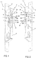
- eine schematische perspektivische Darstellung einer Unterseite eines Gegenkastens oder Schlosskastens für ein Schloss eines beweglichen Flügels,
- Fig. 2
- eine schematische perspektivische Darstellung einer Oberseite des Gegenkastens oder Schlosskastens für ein Schloss eines beweglichen Flügels aus
Fig. 1 , - Fig. 3
- eine schematische Darstellung des Gegenkastens oder Schlosskastens für ein Schloss eines beweglichen Flügels aus
Fig. 1 und 2 ohne Deckelblech mit den erfindungswesentlichen Teile eines Ausführungsbeispiels einer erfindungsgemäßen Druckernussanordnung für einen beweglichen Flügel nach dem Koppeln der Vormontagebaugruppe mit der Druckernuss, - Fig. 4
- eine schematische Darstellung der erfindungsgemäßen Druckernussanordnung für einen beweglichen Flügel aus
Fig. 3 nach der Justierung der Federvorspannung der Federvorrichtung, - Fig. 5
- eine schematische Darstellung der erfindungsgemäßen Druckernussanordnung für einen beweglichen Flügel aus
Fig. 3 und 4 nach Fixierung des zweiten Führungselements, und - Fig. 6
- eine schematische Darstellung der erfindungsgemäßen Druckernussanordnung für einen beweglichen Flügel aus
Fig. 3 bis 5 nach dem Aufsetzen des Deckelblechs und der Fixierung des ersten und zweiten Führungselements am Deckelblech. - Wie aus
Fig. 1 bis 6 ersichtlich ist, umfasst das dargestellte Ausführungsbeispiel eines erfindungsgemäßen Gegenkastens 1 für ein Schloss eines beweglichen Flügels ein Gehäuse 3, eine darin drehbar gelagerte Druckernuss 12 und mindestens ein von der Druckernuss 12 beaufschlagbares nicht näher dargestelltes Betätigungselement, welches bei einer gegen eine Federwirkung erfolgte Betätigung der Druckernuss 12 eine Entriegelung eines zugehörigen Schlosses bewirkt. Hierbei ist die Druckernuss 12 über einen Betätigungsarm 14 mit dem Betätigungselement und über einen Federarm 16 mit einem Federelement 22 einer Federanordnung 20 gekoppelt, welche die Federwirkung erzeugt. Wie ausFig. 1 bis 6 weiter ersichtlich ist, umfasst das Gehäuse 3 des Gegenkastens 1 ein Bodenblech 5 und ein Deckelblech 6, welches auch die Rückwand des Gehäuses 3 bildet und eine Stulpplatte 4, welche eine Vorderwand des Gehäuses 3 ausbildet. In die Stulpplatte ist mindestens eine Öffnung eingebracht, welche ein nicht näher dargestellter Schieber im entriegelten Zustand durchgreift. - Wie aus
Fig. 1 bis 6 ersichtlich ist, kann das dargestellte Gehäuse 3 und die Druckernussanordnung 10 auch für einen erfindungsgemäßen Schlosskasten 2 für ein Schloss eines beweglichen Flügels verwendet werden. - Bei dem beweglichen Flügel kann es sich beispielsweise um einen Türflügel oder einen Fensterflügel handeln.
- Bei einer möglichen Ausführungsform des Gegenkastens 1 für ein Schloss eines Flügels kann das von der Druckernuss 12 beaufschlagbare Betätigungselement bei einer gegen eine Federwirkung erfolgte Betätigung der Druckernuss 12 ein erstes Schubelement in eine erste Betätigungsrichtung betätigen. Das erste Schubelement kann über eine erste Übertragungsvorrichtung mit einem zweiten Schubelement und über eine zweite Übertragungsvorrichtung mit einem Schieber gekoppelt werden. Der Schieber kann zum Einschließen einer Falle und/oder eines Riegels eines Schlosses mit Vollpanikfunktion durch eine korrespondierende Öffnung in einer Stulpplatte 4 in eine aus dem Gehäuse 3 vorstehende Stellung gebracht werden. Das erste Schubelement kann mit einer ersten Schließstange gekoppelt sein, und das zweite Schubelement kann mit einer zweiten Schließstange gekoppelt sein. Zudem kann die erste Übertragungsvorrichtung die erste Betätigungsrichtung des ersten Schubelements in eine entgegengesetzte zweite Betätigungsrichtung des zweiten Schubelements umwandeln. Die zweite Übertragungsvorrichtung kann die erste Betätigungsrichtung des ersten Schubelements in eine dritte Betätigungsrichtung des Schiebers umwandeln. Hierbei kann die erste Übertragungsvorrichtung beispielsweise als Zahnstangenantrieb ausgeführt sein und eine am ersten Schubelement ausgebildete erste Zahnstange umfassen, welche über ein Zahnrad mit einer am zweiten Schubelement ausgebildeten zweiten Zahnstange gekoppelt sein kann.
- Wie aus
Fig. 1 bis 6 weiter ersichtlich ist, umfasst die Druckernussanordnung 10 für einen beweglichen Flügel im dargestellten Ausführungsbeispiel die im Gehäuse 3 drehbar gelagerte Druckernuss 12 und mindestens ein von der Druckernuss 12 beaufschlagbares nicht näher dargestelltes Betätigungselement, welches bei einer gegen eine Federwirkung erfolgten Betätigung der Druckernuss 12 eine Entriegelung eines zugehörigen Schlosses bewirkt. Hierbei ist die Druckernuss 12 über einen Betätigungsarm 14 mit dem Betätigungselement und über einen Federarm 16 mit einem Federelement 22 einer Federanordnung 20 gekoppelt, welche die Federwirkung erzeugt. Erfindungsgemäß umfasst die Federanordnung 20 eine Einstellvorrichtung 24, über welche eine Vorspannkraft des Federelements 22 einstellbar ist. - Wie aus
Fig. 1 bis 6 weiter ersichtlich ist, ist das Federelement 22 im dargestellten Ausführungsbeispiel als Spiralfeder 22A ausgeführt. Wie insbesondere ausFig. 3 bis 5 weiter ersichtlich ist, wirkt der Federarm 16 der Druckernuss 12 auf ein erstes Ende der Spiralfeder 22A. Im dargestellten Ausführungsbeispiel umfasst die Einstellvorrichtung 24 eine Zylinderschraube 26 mit einem Schraubenkopf 26.1 und einem Gewindeschaft 26.2 sowie eine Mutter 28. Eine korrespondierende Vormontagebaugruppe 21 umfasst die Einstellvorrichtung 24 und ein erstes Führungselement 29A. Nach dem Zusammenbau der Vormontagebaugruppe 21 sind das erste Führungselement 29A und die Spiralfeder 22A auf den Gewindeschaft 26.2 aufgeschoben und zwischen dem Schraubenkopf 26.1 und der Mutter 28 verliersicher gehalten. Diese Vormontagebaugruppe 21 kann dann einfach auf das Bodenblech 5 aufgesetzt und mit dem Federarm 16 der Druckernuss 12 gekoppelt werden. Wie ausFig. 3 bis 5 weiter ersichtlich ist, weist der Federarm 16 einen gabelförmigen Endbereich auf, welcher den Gewindeschaft 26.2 zumindest teilweise so umgreift, dass die Mutter 28 auf den Federarm 16 und über den Federarm 16 auf die Spiralfeder 22A wirkt. - Wie aus
Fig. 1 bis 6 weiter ersichtlich ist, ist das erste Führungselement 29A im montierten Zustand am Gehäuse 3 befestigt und führt den Gewindeschaft 26.1 drehbeweglich. Hierbei liegt der Schraubenkopf 26.1 an einer ersten Seite des ersten Führungselements 29A und die Spiralfeder 22A mit einer zweiten Seite an einer der ersten Seite gegenüberliegenden zweiten Seite des ersten Führungselements 29A an. Zudem ist ein zweites Führungselement 29B im Bereich des Schraubenkopfes 26.1 angeordnet und am Gehäuse 3 fixiert. Das zweite Führungselement 29B sichert die Schraube 26 gegen Verdrehen. - Bei der Durchführung des erfindungsgemäßen Verfahrens zur Montage einer Federanordnung 20 für eine Druckernussanordnung 10 wird zuerst die Vormontagebaugruppe 21 zusammengebaut, welche das erste Führungselement 29A, die Spiralfeder 22A ohne Vorspannung, die Schraube 26 und eine Mutter 28 umfasst.
- Im dargestellten Ausführungsbeispiel werden während des Zusammenbaus der Vormontagebaugruppe 21 das erste Führungselement 29A und die Spiralfeder 22A auf den Gewindeschaft 26.2 der Schraube 26 aufgeschoben und anschließend wird die Mutter 28 auf den Gewindeschaft 26.2 aufgeschraubt. Dann wird die Vormontagebaugruppe 21 mit einer montierten Druckernuss 12 gekoppelt.
Fig. 3 zeigt die Druckernussanordnung 10 nach der Kopplung der Vormontagebaugruppe 21 mit der Druckernuss 12. - Wie aus
Fig. 3 weiter ersichtlich ist, umgreift ein Federarm 16 der Druckernuss 12 nach der Kopplung mit der Vormontagebaugruppe 21 den Gewindeschaft 26.2 zumindest teilweise und wirkt auf ein erstes Ende der Spiralfeder 22A. In einem weiteren Schritt wird die Vorspannung der Spiralfeder 22A über die Schraube-Mutter-Verbindung vorjustiert. Die Vorjustierung der Federvorspannung der Spiralfeder 22A wird durch Drehen der Schraube 26 und/oder der Mutter 28 durchgeführt und kann mit herkömmlichem Standardwerkzeug, wie einem passenden Schraubenschlüsse oder einem Schraubendreher ausgeführt werden. Hierbei wirkt die Mutter 28 auf den Federarm 16 und der Schraubenkopf 26.1 auf das erste Führungselement 29A und der wirksame Abstand zwischen dem Federarm 16 und dem ersten Führungselement 29A reduziert sich, in dem das erste Führungselement 29A auf den Federarm 16 zubewegt wird. Dadurch verkürzt sich die wirksame Länge der Spiralfeder 22A und die Spiralfeder 22A wird gespannt. Nach der Vorjustierung der Federvorspannung der Spiralfeder 22A wird das erste Führungselement 29A am Bodenblech 5 fixiert. Im dargestellten Ausführungsbeispiel wird das erste Führungselement 29A mit einer Befestigungsschraube 7, welche durch ein Loch im Bodenblech 5 in eine Gewindebohrung im ersten Führungselement 29A eingeschraubt wird, am Bodenblech 5 befestigt. Nach der Fixierung des ersten Führungselements 29A am Bodenblech 5 ist die Schraube 26 durch das erste Führungselement 29A axial fixiert und drehbeweglich gelagert.Fig. 4 zeigt die Druckernussanordnung 10 nach der Vorjustierung der Federvorspannung der Spiralfeder 22A und der Fixierung des ersten Führungselements 29A am Bodenblech. - Wie aus
Fig. 4 weiter ersichtlich ist, kann jetzt die Justierung der Federvorspannung der Spiralfeder 22A über die Schraube-Mutter-Verbindung durchgeführt werden, bis eine gewünschte Vorspannung der Spiralfeder 22A erreicht ist. Die Justierung der Federvorspannung der Spiralfeder 22A wird durch Drehen der Schraube 26 und/oder der Mutter 28 mit herkömmlichem Standardwerkzeug durchgeführt, wodurch die Mutter 28 auf den Federarm 16 wirkt und dieser auf das erste Führungselement 29A und den Schraubenkopf 26.1 zubewegt wird. Der Schraubenkopf 26.1 bzw. die Schraube 26 ist drehbeweglich am ersten Führungselement 29A gelagert und axial fixiert, so dass sich der wirksame Abstand zwischen dem Federarm 16 und dem ersten Führungselement 29A weiter reduziert. Dadurch wird die wirksame Länge der Spiralfeder 22A weiter verkürzt und die Spiralfeder 22A weiter gespannt. Nach der Justierung der Federvorspannung der Spiralfeder 22A wird das zweite Führungselement 29B am Bodenblech 5 fixiert, wobei das zweite Führungselement 29B die Schraube 26 drehfest fixiert. Im dargestellten Ausführungsbeispiel wird das zweite Führungselement 29B mit einer Befestigungsschraube 7, welche durch ein Loch im Bodenblech 5 in eine Gewindebohrung im zweiten Führungselement 29B eingeschraubt wird, am Bodenblech 5 befestigt. Nach der Fixierung des zweiten Führungselements 29B am Bodenblech 5 ist die Schraube 26 durch das erste Führungselement 29A axial fixiert und durch das zweite Führungselement 29A gegen Verdrehen gesichert.Fig. 5 zeigt die Druckernussanordnung 10 nach der Justierung der Federvorspannung der Spiralfeder 22A und der Fixierung des zweiten Führungselements 29B am Bodenblech. - Wie aus
Fig. 5 weiter ersichtlich ist, kann nun noch eine Feinjustierung bzw. Nachjustierung der Federvorspannung der Spiralfeder 22A durch Drehen der Mutter 28 durchgeführt werden, wodurch die Mutter 28 auf den Federarm 16 wirkt und dieser auf das erste Führungselement 29A und den Schraubenkopf 26.1 zubewegt wird, welcher drehfest am zweiten Führungselement 29B gelagert ist, so dass sich der wirksame Abstand zwischen dem Federarm 16 und dem ersten Führungselement 29A weiter reduziert. Dadurch wird die wirksame Länge der Spiralfeder 22A weiter verkürzt und die Spiralfeder 22A weiter gespannt. Anschließend wird das Deckelblech 6 aufgesetzt und das erste Führungselement 29A und das zweite Führungselement 29B werden am Deckelblech 6 fixiert. Im dargestellten Ausführungsbeispiel werden das erste Führungselement 29A und das zweite Führungselement 29B mit Befestigungsschrauben 8, welche durch Löcher im Deckelblech 6 in korrespondierende Gewindebohrungen im ersten Führungselement 29A und im zweiten Führungselement 29B eingeschraubt werden, am Deckelblech 6 befestigt.Fig. 6 zeigt die Druckernussanordnung 10 nach dem Aufsetzen des Deckelbelchs 6. - Wie aus
Fig. 1, 2 und6 weiter ersichtlich ist, bleibt die Mutter 28 durch eine Öffnung 6.1 im Deckelblech 6 von außen zugänglich. Dadurch kann während des Betriebs die Federvorspannung der Spiralfeder 22A mit herkömmlichem Standardwerkzeug einfach nachjustiert werden. -
- 1
- Gegenkasten
- 2
- Schlosskasten
- 3
- Gehäuse
- 4
- Stulpplatte
- 5
- Bodenblech
- 6
- Deckelblech
- 6.1
- Öffnung
- 7
- Befestigungsschraube (Bodenblech)
- 8
- Befestigungsschraube (Deckelblech)
- 10
- Druckernussanordnung
- 12
- Druckernuss
- 14
- Betätigungsarm
- 16
- Federarm
- 20
- Federanordnung
- 21
- Vormontagebaugruppe
- 22
- Federelement
- 22A
- Spiralfeder
- 24
- Einstellvorrichtung
- 26
- Schraube
- 26.1
- Schraubenkopf
- 26.2
- Gewindeschaft
- 28
- Mutter
- 29A
- erstes Führungselement
- 29B
- zweites Führungselement
Claims (20)
- Druckernussanordnung (10) für einen beweglichen Flügel, mit einer in einem Gehäuse (3) drehbar gelagerten Druckernuss (12), mindestens einem von der Druckernuss (12) beaufschlagbaren Betätigungselement, welches bei einer gegen eine Federwirkung erfolgten Betätigung der Druckernuss (12) eine Entriegelung eines zugehörigen Schlosses bewirkt, wobei die Druckernuss (12) über einen Betätigungsarm (14) mit dem Betätigungselement und über einen Federarm (16) mit einem Federelement (22) einer Federanordnung (20) gekoppelt ist, welche die Federwirkung erzeugt,
dadurch gekennzeichnet,
dass die Federanordnung (20) eine Einstellvorrichtung (24) umfasst, über welche eine Vorspannkraft des Federelements (22) einstellbar ist. - Druckernussanordnung (10) nach Anspruch 1,
dadurch gekennzeichnet,
dass das Federelement (22) als Spiralfeder (22A) ausgeführt ist. - Druckernussanordnung (10) nach Anspruch 2,
dadurch gekennzeichnet,
dass der Federarm (16) der Druckernuss (12) auf ein erstes Ende der Spiralfeder (22A) wirkt. - Druckernussanordnung (1) nach einem der Ansprüche 1 bis 3,
dadurch gekennzeichnet,
dass die Einstellvorrichtung (24) eine Zylinderschraube (26) mit einem Schraubenkopf (26.1) und einem Gewindeschaft (26.2) und eine Mutter (28) umfasst. - Druckernussanordnung (10) nach einem der Ansprüche 1 bis 4,
dadurch gekennzeichnet,
dass eine Vormontagebaugruppe (21) die Einstellvorrichtung (24) und ein erstes Führungselement (29A) umfasst. - Druckernussanordnung (10) nach Anspruch 5,
dadurch gekennzeichnet,
dass das erste Führungselement (29A) und die Spiralfeder (22A) auf den Gewindeschaft (26.2) aufgeschoben und zwischen dem Schraubenkopf (26.1) und der Mutter (28) verliersicher gehalten sind. - Druckernussanordnung (10) nach Anspruch 6,
dadurch gekennzeichnet,
dass der Federarm (16) einen gabelförmigen Endbereich aufweist, welcher den Gewindeschaft (26.2) zumindest teilweise umgreift, wobei die Mutter (28) auf den Federarm (16) und über den Federarm (16) auf die Spiralfeder (22A) wirkt. - Druckernussanordnung (10) nach Anspruch 7,
dadurch gekennzeichnet,
dass das erste Führungselement (29A) im montierten Zustand am Gehäuse (3) befestigt ist und den Gewindeschaft (26.1) drehbeweglich führt, wobei der Schraubenkopf (26.1) an einer ersten Seite des ersten Führungselements (29A) und die Spiralfeder (22A) mit einer zweiten Seite an einer der ersten Seite gegenüberliegenden zweiten Seite des ersten Führungselements (29A) anliegt. - Druckernussanordnung (10) nach einem der Ansprüche 4 bis 8,
dadurch gekennzeichnet,
dass ein zweites Führungselement (29B) im Bereich des Schraubenkopfes (26.1) angeordnet und am Gehäuse (3) fixiert ist, wobei das zweite Führungselement (29B) die Schraube (26) gegen Verdrehen sichert. - Gegenkasten (1) für ein Schloss eines beweglichen Flügels, mit einem Gehäuse (3) und einer Druckernussanordnung (10),
dadurch gekennzeichnet,
dass die Druckernussanordnung (10) nach zumindest einem der Ansprüche 1 bis 9 ausgeführt ist. - Gegenkasten (1) nach Anspruch 10,
dadurch gekennzeichnet,
dass der bewegliche Flügel ein Türflügel oder ein Fensterflügel ist. - Schlosskasten (2) für ein Schloss eines beweglichen Flügels, mit einem Gehäuse (3) und einer Druckernussanordnung (10),
dadurch gekennzeichnet,
dass die Druckernussanordnung (10) nach zumindest einem der Ansprüche 1 bis 9 ausgeführt ist. - Schlosskasten (2) nach Anspruch 12,
dadurch gekennzeichnet,
dass der bewegliche Flügel ein Türflügel oder ein Fensterflügel ist. - Verfahren zur Montage einer Federanordnung (20) für eine Druckernussanordnung (10), welche nach zumindest einem der Ansprüche 1 bis 9 ausgeführt ist, gekennzeichnet durch die Schritte:Zusammenbau einer Vormontagebaugruppe (21), welche ein erstes Führungselement (29A), eine Spiralfeder (22A) ohne Vorspannung, eine Schraube (26) und eine Mutter (28) umfasst,Koppeln der Vormontagebaugruppe (21) mit einer montierten Druckernuss (12), Vorjustierung der Vorspannung der Spiralfeder (22A) über die Schraube-Mutter-Verbindung,Fixieren des ersten Führungselements (29A) am Bodenblech (5),Justierung der Federvorspannung über die Schraube-Mutter-Verbindung bis eine gewünschte Vorspannung der Spiralfeder (22A) erreicht ist,Fixieren eines zweiten Führungselements (29B) am Bodenblech (5), wobei das zweite Führungselement (29B) die Schraube (26) drehfest fixiert.
- Verfahren nach Anspruch 14,
dadurch gekennzeichnet,
dass während des Zusammenbaus der Vormontagebaugruppe (21) das erste Führungselement (29A) und die Spiralfeder (22A) auf einen Gewindeschaft (26.2) der Schraube (26) aufgeschoben werden und anschließend die Mutter (28) auf den Gewindeschaft (26.2) aufgeschraubt wird. - Verfahren nach Anspruch 14 oder 15,
dadurch gekennzeichnet,
dass ein Federarm (16) der Druckernuss (12) nach der Kopplung mit der Vormontagebaugruppe (21) auf ein erstes Ende der Spiralfeder (22A) wirkt und den Gewindeschaft (26.2) zumindest teilweise umgreift. - Verfahren nach einem der Ansprüche 14 bis 16,
dadurch gekennzeichnet,
dass die Vorjustierung der Federvorspannung der Spiralfeder (22A) durch Drehen der Schraube (26) und/oder der Mutter (28) durchgeführt wird, wodurch die Mutter (28) auf den Federarm (16) und der Schraubenkopf (26.1) auf das erste Führungselement (29A) wirkt und sich der wirksame Abstand zwischen dem Federarm (16) und dem ersten Führungselement (29A) reduziert, in dem das erste Führungselement (29A) auf den Federarm (16) zubewegt wird und sich die wirksame Länge der Spiralfeder (22A) verkürzt und die Spiralfeder (22A) gespannt wird. - Verfahren nach Anspruch 17,
dadurch gekennzeichnet,
dass die Justierung der Federvorspannung der Spiralfeder (22A) durch Drehen der Schraube (26) und/oder der Mutter (28) durchgeführt wird, wodurch die Mutter (28) auf den Federarm (16) wirkt und dieser auf das erste Führungselement (29A) und den Schraubenkopf (26.1) zubewegt wird, welcher drehbeweglich am ersten Führungselement (29A) gelagert und axial fixiert ist, so dass sich der wirksame Abstand zwischen dem Federarm (16) und dem ersten Führungselement (29A) weiter reduziert und die wirksame Länge der Spiralfeder (22A) weiter verkürzt und die Spiralfeder (22A) weiter gespannt wird. - Verfahren nach Anspruch 18,
dadurch gekennzeichnet,
dass eine Feinjustierung der Federvorspannung der Spiralfeder (22A) durch Drehen der Mutter (28) durchgeführt wird, wodurch die Mutter (28) auf den Federarm (16) wirkt und dieser auf das erste Führungselement (29A) und den Schraubenkopf (26.1) zubewegt wird, welcher drehfest am zweiten Führungselement (29B) gelagert ist, so dass sich der wirksame Abstand zwischen dem Federarm (16) und dem ersten Führungselement (29A) weiter reduziert und die wirksame Länge der Spiralfeder (22A) weiter verkürzt und die Spiralfeder (22A) weiter gespannt wird. - Verfahren nach einem der Ansprüche 14 bis 19,
dadurch gekennzeichnet,
dass ein Deckelblech (6) aufgesetzt wird, und das erste Führungselement (29A) und das zweite Führungselement (29B) am Deckelblech (6) fixiert werden, wobei die Mutter (28) durch eine Öffnung (6.1) im Deckelblech (6) von außen zugänglich bleibt.
Priority Applications (1)
| Application Number | Priority Date | Filing Date | Title |
|---|---|---|---|
| PL18169604T PL3406827T3 (pl) | 2017-05-23 | 2018-04-26 | Układ orzecha naciskowego do ruchomego skrzydła |
Applications Claiming Priority (1)
| Application Number | Priority Date | Filing Date | Title |
|---|---|---|---|
| DE102017208731.5A DE102017208731A1 (de) | 2017-05-23 | 2017-05-23 | Druckernussanordnung für einen beweglichen Flügel |
Publications (2)
| Publication Number | Publication Date |
|---|---|
| EP3406827A1 true EP3406827A1 (de) | 2018-11-28 |
| EP3406827B1 EP3406827B1 (de) | 2020-08-05 |
Family
ID=62067539
Family Applications (1)
| Application Number | Title | Priority Date | Filing Date |
|---|---|---|---|
| EP18169604.8A Active EP3406827B1 (de) | 2017-05-23 | 2018-04-26 | Druckernussanordnung für einen beweglichen flügel |
Country Status (5)
| Country | Link |
|---|---|
| EP (1) | EP3406827B1 (de) |
| DE (1) | DE102017208731A1 (de) |
| ES (1) | ES2820555T3 (de) |
| HU (1) | HUE051224T2 (de) |
| PL (1) | PL3406827T3 (de) |
Citations (6)
| Publication number | Priority date | Publication date | Assignee | Title |
|---|---|---|---|---|
| GB2323626A (en) * | 1997-03-25 | 1998-09-30 | Newman Tonks Group Plc | Latch assembly with adjustable spring |
| US20030061847A1 (en) * | 2001-09-28 | 2003-04-03 | Morris Eric D. | Mortise lock |
| DE10261129A1 (de) | 2002-12-20 | 2004-07-01 | Geze Gmbh | Schloss |
| EP2468988A2 (de) * | 2010-12-23 | 2012-06-27 | Dorma GmbH + Co. KG | Schloss mit einer Nulllagenverstellung des Türdrückers |
| DE202014003684U1 (de) * | 2014-05-02 | 2014-05-28 | Heinz-Werner Nowak | Drückerverstellung für Glastürschlösser |
| CN104806074A (zh) * | 2015-05-06 | 2015-07-29 | 张治军 | 一种锁紧件及应用该锁紧件的锁 |
Family Cites Families (2)
| Publication number | Priority date | Publication date | Assignee | Title |
|---|---|---|---|---|
| DE20307656U1 (de) | 2003-05-16 | 2004-09-23 | Casma S.P.A. | Ganzglastürschloss |
| DE202009008431U1 (de) | 2009-06-15 | 2009-08-27 | Bks Gmbh | Einsteckschloss |
-
2017
- 2017-05-23 DE DE102017208731.5A patent/DE102017208731A1/de not_active Ceased
-
2018
- 2018-04-26 PL PL18169604T patent/PL3406827T3/pl unknown
- 2018-04-26 EP EP18169604.8A patent/EP3406827B1/de active Active
- 2018-04-26 ES ES18169604T patent/ES2820555T3/es active Active
- 2018-04-26 HU HUE18169604A patent/HUE051224T2/hu unknown
Patent Citations (6)
| Publication number | Priority date | Publication date | Assignee | Title |
|---|---|---|---|---|
| GB2323626A (en) * | 1997-03-25 | 1998-09-30 | Newman Tonks Group Plc | Latch assembly with adjustable spring |
| US20030061847A1 (en) * | 2001-09-28 | 2003-04-03 | Morris Eric D. | Mortise lock |
| DE10261129A1 (de) | 2002-12-20 | 2004-07-01 | Geze Gmbh | Schloss |
| EP2468988A2 (de) * | 2010-12-23 | 2012-06-27 | Dorma GmbH + Co. KG | Schloss mit einer Nulllagenverstellung des Türdrückers |
| DE202014003684U1 (de) * | 2014-05-02 | 2014-05-28 | Heinz-Werner Nowak | Drückerverstellung für Glastürschlösser |
| CN104806074A (zh) * | 2015-05-06 | 2015-07-29 | 张治军 | 一种锁紧件及应用该锁紧件的锁 |
Also Published As
| Publication number | Publication date |
|---|---|
| ES2820555T3 (es) | 2021-04-21 |
| EP3406827B1 (de) | 2020-08-05 |
| HUE051224T2 (hu) | 2021-03-01 |
| DE102017208731A1 (de) | 2018-11-29 |
| PL3406827T3 (pl) | 2021-02-08 |
Similar Documents
| Publication | Publication Date | Title |
|---|---|---|
| WO2003025320A1 (de) | Griffbeschlag | |
| EP2042671A2 (de) | Griffbefestigung und Beschlag mit Griffbefestigung | |
| EP4438836B1 (de) | Schliesssystem und tür oder fenster mit derartigem schliesssystem | |
| DE10233556B4 (de) | Aggregateträger für eine Fahrzeugtür | |
| DE19924028A1 (de) | Kraftfahrzeugtür | |
| EP3913181B1 (de) | Türaufsteller mit lösbarer halterung | |
| WO2002002894A1 (de) | Kraftfahrzeugtürverschluss | |
| DE10332818A1 (de) | Vorrichtung zum Anheben einer Motorhaube | |
| EP3406827B1 (de) | Druckernussanordnung für einen beweglichen flügel | |
| EP4505088A1 (de) | Anschlussgelenkanordnung | |
| DE102022120478A1 (de) | Betätigungshandhabe | |
| EP1525362B1 (de) | System mit einem feststehenden Schließbügel und einer Zuziehvorrichtung | |
| DE102017119252A1 (de) | Funktionskomponente einer Kraftfahrzeugschlossanordnung | |
| DE1500858C3 (de) | Verschluß für Türen oder Fenster | |
| DE102010029985B4 (de) | Fenster, Tür oder dergleichen mit einer Verriegelungsvorrichtung mit Getriebegehäuse sowie Verfahren zur Herstellung eines derartigen Fensters, einer derartigen Tür oder dergleichen | |
| EP4479613B1 (de) | Verriegelungsvorrichtung, türanordnung mit einer solchen verriegelungsvorrichtung und verfahren zur montage einer solchen verriegelungseinrichtung | |
| DE102023114287B3 (de) | Stellantrieb für eine Fahrzeugklappe und Verfahren zur Verschwenkung einer Fahrzeugklappe | |
| DE10322113A1 (de) | Schließmechanismus | |
| DE19800858C2 (de) | Einstellvorrichtung zum Längenausgleich für einen Betätigungszug | |
| DE19956537C1 (de) | Türdrückergarnitur | |
| DE202024102517U1 (de) | Beschlag eines Fensters oder einer Tür | |
| DE202022105658U1 (de) | Verriegelungsvorrichtung, Tür- oder Fensterverschluss und Tür- oder Fensteranordnung | |
| EP1580371B1 (de) | Beschlaganordnung | |
| EP1084660B1 (de) | Vorrichtung zur vertikalen Einstellung für Möbelschubladen | |
| DE202025104657U1 (de) | Beschlag eines Fensters oder einer Tür |
Legal Events
| Date | Code | Title | Description |
|---|---|---|---|
| PUAI | Public reference made under article 153(3) epc to a published international application that has entered the european phase |
Free format text: ORIGINAL CODE: 0009012 |
|
| STAA | Information on the status of an ep patent application or granted ep patent |
Free format text: STATUS: THE APPLICATION HAS BEEN PUBLISHED |
|
| AK | Designated contracting states |
Kind code of ref document: A1 Designated state(s): AL AT BE BG CH CY CZ DE DK EE ES FI FR GB GR HR HU IE IS IT LI LT LU LV MC MK MT NL NO PL PT RO RS SE SI SK SM TR |
|
| AX | Request for extension of the european patent |
Extension state: BA ME |
|
| STAA | Information on the status of an ep patent application or granted ep patent |
Free format text: STATUS: REQUEST FOR EXAMINATION WAS MADE |
|
| 17P | Request for examination filed |
Effective date: 20190515 |
|
| RBV | Designated contracting states (corrected) |
Designated state(s): AL AT BE BG CH CY CZ DE DK EE ES FI FR GB GR HR HU IE IS IT LI LT LU LV MC MK MT NL NO PL PT RO RS SE SI SK SM TR |
|
| STAA | Information on the status of an ep patent application or granted ep patent |
Free format text: STATUS: EXAMINATION IS IN PROGRESS |
|
| 17Q | First examination report despatched |
Effective date: 20191008 |
|
| GRAP | Despatch of communication of intention to grant a patent |
Free format text: ORIGINAL CODE: EPIDOSNIGR1 |
|
| STAA | Information on the status of an ep patent application or granted ep patent |
Free format text: STATUS: GRANT OF PATENT IS INTENDED |
|
| INTG | Intention to grant announced |
Effective date: 20200416 |
|
| GRAS | Grant fee paid |
Free format text: ORIGINAL CODE: EPIDOSNIGR3 |
|
| GRAA | (expected) grant |
Free format text: ORIGINAL CODE: 0009210 |
|
| STAA | Information on the status of an ep patent application or granted ep patent |
Free format text: STATUS: THE PATENT HAS BEEN GRANTED |
|
| AK | Designated contracting states |
Kind code of ref document: B1 Designated state(s): AL AT BE BG CH CY CZ DE DK EE ES FI FR GB GR HR HU IE IS IT LI LT LU LV MC MK MT NL NO PL PT RO RS SE SI SK SM TR |
|
| REG | Reference to a national code |
Ref country code: GB Ref legal event code: FG4D Free format text: NOT ENGLISH |
|
| REG | Reference to a national code |
Ref country code: CH Ref legal event code: EP |
|
| REG | Reference to a national code |
Ref country code: AT Ref legal event code: REF Ref document number: 1298911 Country of ref document: AT Kind code of ref document: T Effective date: 20200815 |
|
| REG | Reference to a national code |
Ref country code: DE Ref legal event code: R096 Ref document number: 502018002064 Country of ref document: DE |
|
| REG | Reference to a national code |
Ref country code: IE Ref legal event code: FG4D Free format text: LANGUAGE OF EP DOCUMENT: GERMAN |
|
| REG | Reference to a national code |
Ref country code: NL Ref legal event code: FP |
|
| REG | Reference to a national code |
Ref country code: LT Ref legal event code: MG4D |
|
| PG25 | Lapsed in a contracting state [announced via postgrant information from national office to epo] |
Ref country code: FI Free format text: LAPSE BECAUSE OF FAILURE TO SUBMIT A TRANSLATION OF THE DESCRIPTION OR TO PAY THE FEE WITHIN THE PRESCRIBED TIME-LIMIT Effective date: 20200805 Ref country code: LT Free format text: LAPSE BECAUSE OF FAILURE TO SUBMIT A TRANSLATION OF THE DESCRIPTION OR TO PAY THE FEE WITHIN THE PRESCRIBED TIME-LIMIT Effective date: 20200805 Ref country code: PT Free format text: LAPSE BECAUSE OF FAILURE TO SUBMIT A TRANSLATION OF THE DESCRIPTION OR TO PAY THE FEE WITHIN THE PRESCRIBED TIME-LIMIT Effective date: 20201207 Ref country code: HR Free format text: LAPSE BECAUSE OF FAILURE TO SUBMIT A TRANSLATION OF THE DESCRIPTION OR TO PAY THE FEE WITHIN THE PRESCRIBED TIME-LIMIT Effective date: 20200805 Ref country code: NO Free format text: LAPSE BECAUSE OF FAILURE TO SUBMIT A TRANSLATION OF THE DESCRIPTION OR TO PAY THE FEE WITHIN THE PRESCRIBED TIME-LIMIT Effective date: 20201105 Ref country code: GR Free format text: LAPSE BECAUSE OF FAILURE TO SUBMIT A TRANSLATION OF THE DESCRIPTION OR TO PAY THE FEE WITHIN THE PRESCRIBED TIME-LIMIT Effective date: 20201106 Ref country code: SE Free format text: LAPSE BECAUSE OF FAILURE TO SUBMIT A TRANSLATION OF THE DESCRIPTION OR TO PAY THE FEE WITHIN THE PRESCRIBED TIME-LIMIT Effective date: 20200805 Ref country code: BG Free format text: LAPSE BECAUSE OF FAILURE TO SUBMIT A TRANSLATION OF THE DESCRIPTION OR TO PAY THE FEE WITHIN THE PRESCRIBED TIME-LIMIT Effective date: 20201105 |
|
| PG25 | Lapsed in a contracting state [announced via postgrant information from national office to epo] |
Ref country code: RS Free format text: LAPSE BECAUSE OF FAILURE TO SUBMIT A TRANSLATION OF THE DESCRIPTION OR TO PAY THE FEE WITHIN THE PRESCRIBED TIME-LIMIT Effective date: 20200805 Ref country code: LV Free format text: LAPSE BECAUSE OF FAILURE TO SUBMIT A TRANSLATION OF THE DESCRIPTION OR TO PAY THE FEE WITHIN THE PRESCRIBED TIME-LIMIT Effective date: 20200805 Ref country code: IS Free format text: LAPSE BECAUSE OF FAILURE TO SUBMIT A TRANSLATION OF THE DESCRIPTION OR TO PAY THE FEE WITHIN THE PRESCRIBED TIME-LIMIT Effective date: 20201205 |
|
| REG | Reference to a national code |
Ref country code: HU Ref legal event code: AG4A Ref document number: E051224 Country of ref document: HU |
|
| REG | Reference to a national code |
Ref country code: ES Ref legal event code: FG2A Ref document number: 2820555 Country of ref document: ES Kind code of ref document: T3 Effective date: 20210421 |
|
| PG25 | Lapsed in a contracting state [announced via postgrant information from national office to epo] |
Ref country code: EE Free format text: LAPSE BECAUSE OF FAILURE TO SUBMIT A TRANSLATION OF THE DESCRIPTION OR TO PAY THE FEE WITHIN THE PRESCRIBED TIME-LIMIT Effective date: 20200805 Ref country code: DK Free format text: LAPSE BECAUSE OF FAILURE TO SUBMIT A TRANSLATION OF THE DESCRIPTION OR TO PAY THE FEE WITHIN THE PRESCRIBED TIME-LIMIT Effective date: 20200805 Ref country code: RO Free format text: LAPSE BECAUSE OF FAILURE TO SUBMIT A TRANSLATION OF THE DESCRIPTION OR TO PAY THE FEE WITHIN THE PRESCRIBED TIME-LIMIT Effective date: 20200805 Ref country code: SM Free format text: LAPSE BECAUSE OF FAILURE TO SUBMIT A TRANSLATION OF THE DESCRIPTION OR TO PAY THE FEE WITHIN THE PRESCRIBED TIME-LIMIT Effective date: 20200805 |
|
| REG | Reference to a national code |
Ref country code: DE Ref legal event code: R097 Ref document number: 502018002064 Country of ref document: DE |
|
| PG25 | Lapsed in a contracting state [announced via postgrant information from national office to epo] |
Ref country code: AL Free format text: LAPSE BECAUSE OF FAILURE TO SUBMIT A TRANSLATION OF THE DESCRIPTION OR TO PAY THE FEE WITHIN THE PRESCRIBED TIME-LIMIT Effective date: 20200805 |
|
| PLBE | No opposition filed within time limit |
Free format text: ORIGINAL CODE: 0009261 |
|
| STAA | Information on the status of an ep patent application or granted ep patent |
Free format text: STATUS: NO OPPOSITION FILED WITHIN TIME LIMIT |
|
| PG25 | Lapsed in a contracting state [announced via postgrant information from national office to epo] |
Ref country code: SK Free format text: LAPSE BECAUSE OF FAILURE TO SUBMIT A TRANSLATION OF THE DESCRIPTION OR TO PAY THE FEE WITHIN THE PRESCRIBED TIME-LIMIT Effective date: 20200805 |
|
| 26N | No opposition filed |
Effective date: 20210507 |
|
| PG25 | Lapsed in a contracting state [announced via postgrant information from national office to epo] |
Ref country code: SI Free format text: LAPSE BECAUSE OF FAILURE TO SUBMIT A TRANSLATION OF THE DESCRIPTION OR TO PAY THE FEE WITHIN THE PRESCRIBED TIME-LIMIT Effective date: 20200805 |
|
| PG25 | Lapsed in a contracting state [announced via postgrant information from national office to epo] |
Ref country code: MC Free format text: LAPSE BECAUSE OF FAILURE TO SUBMIT A TRANSLATION OF THE DESCRIPTION OR TO PAY THE FEE WITHIN THE PRESCRIBED TIME-LIMIT Effective date: 20200805 |
|
| PG25 | Lapsed in a contracting state [announced via postgrant information from national office to epo] |
Ref country code: IE Free format text: LAPSE BECAUSE OF NON-PAYMENT OF DUE FEES Effective date: 20210426 |
|
| PG25 | Lapsed in a contracting state [announced via postgrant information from national office to epo] |
Ref country code: IS Free format text: LAPSE BECAUSE OF FAILURE TO SUBMIT A TRANSLATION OF THE DESCRIPTION OR TO PAY THE FEE WITHIN THE PRESCRIBED TIME-LIMIT Effective date: 20201205 |
|
| P01 | Opt-out of the competence of the unified patent court (upc) registered |
Effective date: 20230510 |
|
| PG25 | Lapsed in a contracting state [announced via postgrant information from national office to epo] |
Ref country code: CY Free format text: LAPSE BECAUSE OF FAILURE TO SUBMIT A TRANSLATION OF THE DESCRIPTION OR TO PAY THE FEE WITHIN THE PRESCRIBED TIME-LIMIT Effective date: 20200805 |
|
| PGFP | Annual fee paid to national office [announced via postgrant information from national office to epo] |
Ref country code: NL Payment date: 20230419 Year of fee payment: 6 Ref country code: LU Payment date: 20230419 Year of fee payment: 6 |
|
| PGFP | Annual fee paid to national office [announced via postgrant information from national office to epo] |
Ref country code: IT Payment date: 20230426 Year of fee payment: 6 Ref country code: FR Payment date: 20230424 Year of fee payment: 6 Ref country code: ES Payment date: 20230627 Year of fee payment: 6 Ref country code: CZ Payment date: 20230419 Year of fee payment: 6 |
|
| PGFP | Annual fee paid to national office [announced via postgrant information from national office to epo] |
Ref country code: HU Payment date: 20230421 Year of fee payment: 6 |
|
| PGFP | Annual fee paid to national office [announced via postgrant information from national office to epo] |
Ref country code: BE Payment date: 20230419 Year of fee payment: 6 |
|
| PGFP | Annual fee paid to national office [announced via postgrant information from national office to epo] |
Ref country code: GB Payment date: 20230419 Year of fee payment: 6 |
|
| PG25 | Lapsed in a contracting state [announced via postgrant information from national office to epo] |
Ref country code: MK Free format text: LAPSE BECAUSE OF FAILURE TO SUBMIT A TRANSLATION OF THE DESCRIPTION OR TO PAY THE FEE WITHIN THE PRESCRIBED TIME-LIMIT Effective date: 20200805 |
|
| PG25 | Lapsed in a contracting state [announced via postgrant information from national office to epo] |
Ref country code: MT Free format text: LAPSE BECAUSE OF FAILURE TO SUBMIT A TRANSLATION OF THE DESCRIPTION OR TO PAY THE FEE WITHIN THE PRESCRIBED TIME-LIMIT Effective date: 20200805 |
|
| REG | Reference to a national code |
Ref country code: NL Ref legal event code: MM Effective date: 20240501 |
|
| PG25 | Lapsed in a contracting state [announced via postgrant information from national office to epo] |
Ref country code: LU Free format text: LAPSE BECAUSE OF NON-PAYMENT OF DUE FEES Effective date: 20240426 |
|
| GBPC | Gb: european patent ceased through non-payment of renewal fee |
Effective date: 20240426 |
|
| REG | Reference to a national code |
Ref country code: BE Ref legal event code: MM Effective date: 20240430 |
|
| PG25 | Lapsed in a contracting state [announced via postgrant information from national office to epo] |
Ref country code: LU Free format text: LAPSE BECAUSE OF NON-PAYMENT OF DUE FEES Effective date: 20240426 |
|
| PG25 | Lapsed in a contracting state [announced via postgrant information from national office to epo] |
Ref country code: HU Free format text: LAPSE BECAUSE OF NON-PAYMENT OF DUE FEES Effective date: 20240427 |
|
| PG25 | Lapsed in a contracting state [announced via postgrant information from national office to epo] |
Ref country code: NL Free format text: LAPSE BECAUSE OF NON-PAYMENT OF DUE FEES Effective date: 20240501 Ref country code: BE Free format text: LAPSE BECAUSE OF NON-PAYMENT OF DUE FEES Effective date: 20240430 |
|
| PG25 | Lapsed in a contracting state [announced via postgrant information from national office to epo] |
Ref country code: GB Free format text: LAPSE BECAUSE OF NON-PAYMENT OF DUE FEES Effective date: 20240426 |
|
| PG25 | Lapsed in a contracting state [announced via postgrant information from national office to epo] |
Ref country code: FR Free format text: LAPSE BECAUSE OF NON-PAYMENT OF DUE FEES Effective date: 20240430 |
|
| PG25 | Lapsed in a contracting state [announced via postgrant information from national office to epo] |
Ref country code: CZ Free format text: LAPSE BECAUSE OF NON-PAYMENT OF DUE FEES Effective date: 20240426 |
|
| PG25 | Lapsed in a contracting state [announced via postgrant information from national office to epo] |
Ref country code: NL Free format text: LAPSE BECAUSE OF NON-PAYMENT OF DUE FEES Effective date: 20240501 Ref country code: HU Free format text: LAPSE BECAUSE OF NON-PAYMENT OF DUE FEES Effective date: 20240427 Ref country code: GB Free format text: LAPSE BECAUSE OF NON-PAYMENT OF DUE FEES Effective date: 20240426 Ref country code: FR Free format text: LAPSE BECAUSE OF NON-PAYMENT OF DUE FEES Effective date: 20240430 Ref country code: CZ Free format text: LAPSE BECAUSE OF NON-PAYMENT OF DUE FEES Effective date: 20240426 Ref country code: BE Free format text: LAPSE BECAUSE OF NON-PAYMENT OF DUE FEES Effective date: 20240430 |
|
| PG25 | Lapsed in a contracting state [announced via postgrant information from national office to epo] |
Ref country code: IT Free format text: LAPSE BECAUSE OF NON-PAYMENT OF DUE FEES Effective date: 20240426 |
|
| REG | Reference to a national code |
Ref country code: ES Ref legal event code: FD2A Effective date: 20250530 |
|
| PG25 | Lapsed in a contracting state [announced via postgrant information from national office to epo] |
Ref country code: ES Free format text: LAPSE BECAUSE OF NON-PAYMENT OF DUE FEES Effective date: 20240427 |
|
| PG25 | Lapsed in a contracting state [announced via postgrant information from national office to epo] |
Ref country code: TR Free format text: LAPSE BECAUSE OF FAILURE TO SUBMIT A TRANSLATION OF THE DESCRIPTION OR TO PAY THE FEE WITHIN THE PRESCRIBED TIME-LIMIT Effective date: 20200805 |
|
| REG | Reference to a national code |
Ref country code: CH Ref legal event code: U11 Free format text: ST27 STATUS EVENT CODE: U-0-0-U10-U11 (AS PROVIDED BY THE NATIONAL OFFICE) Effective date: 20260501 |
|
| PGFP | Annual fee paid to national office [announced via postgrant information from national office to epo] |
Ref country code: PL Payment date: 20260416 Year of fee payment: 9 |
|
| PGFP | Annual fee paid to national office [announced via postgrant information from national office to epo] |
Ref country code: DE Payment date: 20260430 Year of fee payment: 9 |
|
| PGFP | Annual fee paid to national office [announced via postgrant information from national office to epo] |
Ref country code: AT Payment date: 20260421 Year of fee payment: 9 |
|
| PGFP | Annual fee paid to national office [announced via postgrant information from national office to epo] |
Ref country code: CH Payment date: 20260501 Year of fee payment: 9 |