EP3403733B1 - Innenwaschvorrichtung für behälter - Google Patents
Innenwaschvorrichtung für behälter Download PDFInfo
- Publication number
- EP3403733B1 EP3403733B1 EP18171853.7A EP18171853A EP3403733B1 EP 3403733 B1 EP3403733 B1 EP 3403733B1 EP 18171853 A EP18171853 A EP 18171853A EP 3403733 B1 EP3403733 B1 EP 3403733B1
- Authority
- EP
- European Patent Office
- Prior art keywords
- section
- incorporates
- washing device
- internal washing
- containers according
- Prior art date
- Legal status (The legal status is an assumption and is not a legal conclusion. Google has not performed a legal analysis and makes no representation as to the accuracy of the status listed.)
- Active
Links
Images









Classifications
-
- B—PERFORMING OPERATIONS; TRANSPORTING
- B05—SPRAYING OR ATOMISING IN GENERAL; APPLYING FLUENT MATERIALS TO SURFACES, IN GENERAL
- B05B—SPRAYING APPARATUS; ATOMISING APPARATUS; NOZZLES
- B05B13/00—Machines or plants for applying liquids or other fluent materials to surfaces of objects or other work by spraying, not covered by groups B05B1/00 - B05B11/00
- B05B13/06—Machines or plants for applying liquids or other fluent materials to surfaces of objects or other work by spraying, not covered by groups B05B1/00 - B05B11/00 specially designed for treating the inside of hollow bodies
-
- B—PERFORMING OPERATIONS; TRANSPORTING
- B60—VEHICLES IN GENERAL
- B60S—SERVICING, CLEANING, REPAIRING, SUPPORTING, LIFTING, OR MANOEUVRING OF VEHICLES, NOT OTHERWISE PROVIDED FOR
- B60S3/00—Vehicle cleaning apparatus not integral with vehicles
- B60S3/008—Vehicle cleaning apparatus not integral with vehicles for interiors of land vehicles
-
- B—PERFORMING OPERATIONS; TRANSPORTING
- B05—SPRAYING OR ATOMISING IN GENERAL; APPLYING FLUENT MATERIALS TO SURFACES, IN GENERAL
- B05B—SPRAYING APPARATUS; ATOMISING APPARATUS; NOZZLES
- B05B13/00—Machines or plants for applying liquids or other fluent materials to surfaces of objects or other work by spraying, not covered by groups B05B1/00 - B05B11/00
- B05B13/02—Means for supporting work; Arrangement or mounting of spray heads; Adaptation or arrangement of means for feeding work
- B05B13/04—Means for supporting work; Arrangement or mounting of spray heads; Adaptation or arrangement of means for feeding work the spray heads being moved during spraying operation
- B05B13/0405—Means for supporting work; Arrangement or mounting of spray heads; Adaptation or arrangement of means for feeding work the spray heads being moved during spraying operation with reciprocating or oscillating spray heads
- B05B13/041—Means for supporting work; Arrangement or mounting of spray heads; Adaptation or arrangement of means for feeding work the spray heads being moved during spraying operation with reciprocating or oscillating spray heads with spray heads reciprocating along a straight line
-
- B—PERFORMING OPERATIONS; TRANSPORTING
- B08—CLEANING
- B08B—CLEANING IN GENERAL; PREVENTION OF FOULING IN GENERAL
- B08B9/00—Cleaning hollow articles by methods or apparatus specially adapted thereto
- B08B9/08—Cleaning containers, e.g. tanks
-
- B—PERFORMING OPERATIONS; TRANSPORTING
- B08—CLEANING
- B08B—CLEANING IN GENERAL; PREVENTION OF FOULING IN GENERAL
- B08B9/00—Cleaning hollow articles by methods or apparatus specially adapted thereto
- B08B9/08—Cleaning containers, e.g. tanks
- B08B9/093—Cleaning containers, e.g. tanks by the force of jets or sprays
-
- F—MECHANICAL ENGINEERING; LIGHTING; HEATING; WEAPONS; BLASTING
- F16—ENGINEERING ELEMENTS AND UNITS; GENERAL MEASURES FOR PRODUCING AND MAINTAINING EFFECTIVE FUNCTIONING OF MACHINES OR INSTALLATIONS; THERMAL INSULATION IN GENERAL
- F16H—GEARING
- F16H19/00—Gearings comprising essentially only toothed gears or friction members and not capable of conveying indefinitely-continuing rotary motion
- F16H19/02—Gearings comprising essentially only toothed gears or friction members and not capable of conveying indefinitely-continuing rotary motion for interconverting rotary or oscillating motion and reciprocating motion
- F16H19/04—Gearings comprising essentially only toothed gears or friction members and not capable of conveying indefinitely-continuing rotary motion for interconverting rotary or oscillating motion and reciprocating motion comprising a rack
-
- F—MECHANICAL ENGINEERING; LIGHTING; HEATING; WEAPONS; BLASTING
- F16—ENGINEERING ELEMENTS AND UNITS; GENERAL MEASURES FOR PRODUCING AND MAINTAINING EFFECTIVE FUNCTIONING OF MACHINES OR INSTALLATIONS; THERMAL INSULATION IN GENERAL
- F16H—GEARING
- F16H19/00—Gearings comprising essentially only toothed gears or friction members and not capable of conveying indefinitely-continuing rotary motion
- F16H19/02—Gearings comprising essentially only toothed gears or friction members and not capable of conveying indefinitely-continuing rotary motion for interconverting rotary or oscillating motion and reciprocating motion
- F16H19/04—Gearings comprising essentially only toothed gears or friction members and not capable of conveying indefinitely-continuing rotary motion for interconverting rotary or oscillating motion and reciprocating motion comprising a rack
- F16H2019/046—Facilitating the engagement or stopping of racks
Definitions
- the present invention relates to an internal washing device for containers, trailers, truck boxes and the like that incorporates a novel system that can be extended to access the inside of the space to be washed. It can be actuated by a single motor and it incorporates a support that provides an inclination at which the inside of the container can be accessed even if it is not aligned with the device.
- the search is carried out when devices aimed at cleaning the inside of containers in general are involved. This task is crucial in order to reuse the containers in the transport and storage of different types of products, especially given the traces they leave behind, either due to spills or rubbing of both liquid and solid products that would contaminate products transported afterwards.
- Patent document US-1504550 describes an internal washing device for containers basically formed by an extendable crane jib or arm, supported horizontally on a platform.
- the jib incorporates wheels on the free end thereof to move inside the container actuated by a motor.
- the structure of the jib incorporates hoses or cleaning mechanisms suitable for cleaning.
- Patent document DE-102012024887 describes a vehicle that incorporates a front arm that incorporates several cleaning devices. The vehicle is introduced inside the container and it proceeds to wash the container.
- Patent document ES-2398275 describes a vehicle that incorporates a horizontal roller that can be lifted on the front part and two vertical rollers on each side of the horizontal roller. The vehicle is introduced into the container and it proceeds to wash the inner surface of the container in a way that is similar to that used by machines for the external washing of vehicles.
- Patent document EP-0256699 describes a device that incorporates a coiled hose connected to a vehicle. The vehicle is introduced into the container and pressure is provided to the hose to proceed to wash the inside.
- Patent document WO2011141354A1 which discloses an internal washing device for containers in accordance with the preamble of claim 1, relates to a cleaning system that comprises: a carrier movable in a longitudinal direction. It also comprises a washing head pivotally mounted on a front surface of the carrier and about an axis of said washing head. It also comprises at least one vertical rinsing line mounted on the carrier so as to be capable of moving between a first position in which said line diffuses a rinsing fluid in a transverse direction and a second position in which said line diffuses the rinsing fluid in the longitudinal direction. It also comprises a control device adapted so as to control the supply and pivoting of the washing head during a washing operation, and so as to control the supply and movement of the vertical rinsing line during a rinsing operation.
- patent document KR-0138696 describes a device that has a base on which several telescopically extendable U-shaped beams stacked one inside of another are stacked.
- the U-shaped beams incorporate toothed external edges.
- a pinion actuated by a motor, engages with the corresponding beam.
- the pinion descends to engage with the following beam, and so on until reaching the final beam.
- To retract the beams the same shall occur, such that in this case the pinion rises to engage with the following beam until all of the beams are retracted.
- This movement of the pinion is carried out by means of a device that incorporates a sphere and spring pawl that has several problems. Firstly, it implies a limitation on the force with which the extended sections move, the resistance to the disengagement to which the pawl is adjusted by the traction motor itself when retracting the beams having to be overcome. This system also has the drawback that, if a pawl of one of the already extended beams is released, the synchronization of the teeth of the involved beams would be lost, leading to locking at the time of the corresponding engagement. This synchronization is also lost due to the movement of the pinion to engage with the different beams.
- the present invention shows substantial improvement with respect to the device and process for retracting the beams in view of this document, the device incorporating toothed sections whose ends comprise pull and push pawls that act on the following section that is going to start moving and that, due to the grip positions thereof, ensure the synchronization of each section to be engaged with the pinions of the drive shaft at all times, allowing the extending and retracting movement to be carried out as many times as established and making the telescopic movement of the different sections to resemble that of a rail of a single section.
- interference in the movement of the different sections would not affect the operations of the device having to stop it, but instead it would only create the need to remove the interference.
- Another advantage is due to the fact that a drive shaft has pinions that directly engage with each toothed section without needing to move.
- the present invention describes an internal washing device for containers in accordance with claim 1.
- washing device of the invention is described below, describing the simplifications that have been made in the figures.
- the washing device of the invention is intended for the internal washing of containers, truck boxes, trailers and the like, although, throughout the specification, reference is only made to containers.
- the base (4) incorporates the very components of the washing system such as, for example, a hose connected to a water dispenser. This hose is fastened to the extendable arm as described later.
- the base (4) can be fastened to a loading dock or be transported to a specific location where there is a container to be cleaned. It can also incorporate wheels for the movement thereof with a locking mechanism that disables them when necessary.
- the extendable arm is made up of three sections (1, 2, 3), although the number can differ.
- the novelty of the invention is based on the system for extending the cleaning arm, which is why the cleaning elements have not been represented in the figures, given they are not determining elements.
- the device incorporates a hose connected to a water dispenser or fountain that is fastened to the structure of the base (4) and the end of which is fastened to the initial section (1) that can be extended to clean the container.
- the hose in the base (4) can be coiled in a device that releases or retracts it depending on whether the sections (1, 2, 3) of the arm extend or retract.
- This device can be activated, for example, by means of a spring.
- the mechanism for extending and retracting the sections (1, 2, 3) of the arm is actuated by means of a motor (25) connected to the drive shaft (26) that incorporates at least one pinion (5) for connection thereof to the sections (1, 2, 3).
- Each section (1, 2, 3) of the arm is configured as a U-shaped plate comprising a toothed segment along the section (1, 2, 3) intended to engage with the pinions (5) of the drive shaft (26), which is fastened on the base (4) together with the motor (25).
- each section (1, 2, 3) incorporates two toothed segments.
- the drive shaft (26) incorporates a pinion (5) for each section (1, 2, 3).
- the drive shaft (26) incorporates a pinion (5) for each toothed segment of each section (1, 2, 3).
- the change in direction of the movement of the sections (1, 2, 3) is simply carried out by inverting the direction of rotation of the motor (25).
- the device comprises a base (4) with a structure comprising at least one pinion (5), a set formed by a first brake (11) and a first cam (13) and a second set formed by a second brake (12) and a second cam (14).
- the sections (1, 2, 3) are positioned in parallel, such that the telescopic movement of the different sections (1, 2, 3) resembles that of a rail of a single section (1, 2, 3) as described later.
- Each section (1, 2, 3) incorporates a stop (17, 18, 19) and a tilting push pawl (8, 9, 10) on the rear end with a protrusion on the end.
- the first additional segment (2) and the second additional segment (3) incorporate, on the other end, a tilting L-shaped pull pawl (6, 7) that incorporates a protrusion on the end of one of the flanges thereof and a bolt (22, 23), on the end of the other flange, perpendicular to the surface, which is why it is not represented in Figure 1 .
- the initial section (1) incorporates a wheel for supporting the complete device on the free end.
- Figures 2a and 2b show three exploded sections (1, 2, 3) and the base (4) with the structure where the sections (1, 2, 3) are housed, showing a support (24) for fastening to the floor and the motor (25) responsible for activating the pinion (5) in side and front views, respectively.
- Figure 3 shows a cross section view of the base (4) and the three sections (1, 2, 3) in a form of representation that incorporates two toothed longitudinal segments for each section (1, 2, 3) where the drive shaft (26) incorporates the same number of pinions (5), such that each toothed segment engages with a pinion (5).
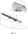
- FIG. 4 shows the device located on a loading dock with the initial section (1) in the extending process.
- each segment (1, 2, 3) incorporates a pair of wheels on the forward end, such that the structure does not need to be configured to support all the weight of the three sections (1, 2, 3) when they are extended, but rather each section (1, 2, 3) only supports its own weight.
- Figures 5a-5d show the effect of the support (24) of the device due to the length it has.
- the support (24) is away from the position of the center of gravity of the device, such that it is never going to be horizontal.
- the support (24) is in a position closer to the working end, supported on the opposite end. This inclination prevents problems with aligning a container with the floor of the loading dock where the device is located.
- the device is horizontal when a specific length of the initial section (1) has been extended. At this time, the device will continue to tilt, such that the wheels of the free end of the initial section (1) rest on the floor of the container, as shown in Figure 5c .
- the device will continue to rest on the floor of the container, as shown in Figure 5d , until they are completely extended, either by means of the wheels of the initial section (1) or by also resting on the wheels of the other sections (2, 3).
- the device behaves in a way that is similar to movement in the opposite direction, when the sections (1, 2, 3) are retracted to end in the initial position.
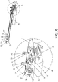
- Figure 6 shows the machine with the sections (1, 2, 3) in a completely retracted position.
- the protrusions of the pull pawls (6, 7) are adjusted in the corresponding brakes (11, 12), anchoring the corresponding sections (2, 3).
- the pinion (5) upon activating the pinion (5) by means of the motor, only the initial section (1) is deployed, being extended to the maximum length thereof.
- Figure 7 shows the situation of the initial section (1) moments before it is completely extended.
- the first stop (17) comes in contact with the first bolt (22) making the first pull pawl (6) rotate over its entire path until coming in contact with the first head (20).
- the rotation of the first pull pawl (6) releases the first additional section (2) of the first brake (11), being arranged to be pulled by the initial section (1), as shown in Figure 8 .
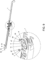
- Figure 9 shows how the pinion (5) stops engaging with the initial section (1) to engage with the first additional section (2), which pushes the initial section (1) due to the fact that, at that moment, the protrusion of the first push pawl (8) has fit into the first recess (15).
- Figure 10 shows the first additional section (2) being expanded and moving the initial section (1) and the second additional section (3) still being immobile, since the second pull pawl (7) is anchored to the second brake (12).
- Figure 11 shows the situation of the first additional section (2) moments before it is completely extended.
- the second stop (18) comes in contact with the second bolt (23) making the second pull pawl (7) rotate throughout its entire path until coming in contact with the second head (21).
- the rotation of the second pull pawl (6) releases the second additional section (3) of the second brake (12), being arranged to be pulled by the first additional section (2).
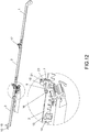
- Figure 12 shows how the pinion (5) engages with the second additional section (3), which pushes the first additional section (2) due to the fact that, at that moment, the protrusion of the second push pawl (9) has fit into the second recess (16).
- the first additional segment (2) continues pulling the initial section (1).
- the second additional section (3) reaches the end of its path, marked by a position determined beforehand that can be defined by an element, not shown in the figures, on which the protrusion of the third push pawl (10) or the third stop (19) hooks, such that the movement of the second additional section (3) in that direction is limited and it is not necessary to create a new component in the second additional section (3) that distinguishes it from the first additional section (2).
- This situation can be extended to an arm that incorporates a greater number of sections (1, 2, 3), where the last section does not have to be different from the intermediate sections. Thus, only the initial section (1) is different from the rest.
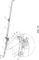
- Figure 13 shows the movement of retracting the second additional section (3), which pulls the first additional section (2) by means of pushing the second bolt (23) through the second head (21), as occurs between the first additional section (2) and the initial section (1).
- the push pawls (8, 9) do not have carry out any function in this case.
- Figure 14 shows how the pinion (5) has started to engage with the first additional section (2).
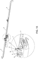
- the second additional section (3) is still pushed by the pinion (5), since the second push pawl (9) is still anchored to the second recess (16). This situation lasts until the second push pawl (9) comes in contact with the second cam, as shown in Figure 15 , which releases the second push pawl (9) and ends the movement of the second additional section (3).
- Figure 16 shows the movement of the first additional section (2) pushed by the pinion (5).
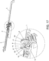
- Figure 17 shows the end of the path of the first additional section (2), the first push pawl (8) having come in contact with the first cam (13) and being unanchored from the first recess (15), such that only the pinion (5) moves the initial section (1).
- the movement of the initial section (1) ends when the initial section (1) reaches the end of its trajectory.
- the brakes (11, 12) and the cams (13, 14) can be incorporated in the segment (1, 2, 3) following that of the movement instead of being in a fixed location.
Landscapes
- Engineering & Computer Science (AREA)
- Mechanical Engineering (AREA)
- General Engineering & Computer Science (AREA)
- Electric Suction Cleaners (AREA)
- Refuse-Collection Vehicles (AREA)
- Vehicle Cleaning, Maintenance, Repair, Refitting, And Outriggers (AREA)
- Transmission Devices (AREA)
Claims (8)
- Innenwaschvorrichtung für Container, umfassend eine Basis (4), eine Struktur mit einem Anfangsabschnitt (1) und wenigstens einem zusätzlichen Abschnitt (2, 3), wobei die Struktur teleskopisch von einem vorderen Ende zu einem hinteren Ende ausziehbar ist und in dem wenigstens ein Reinigungselement untergebracht ist, dadurch gekennzeichnet, dass:- die Basis (4) eine Antriebswelle (26) aufweist, die von einem Motor (25) betätigt wird,- jeder Abschnitt (1, 2, 3) wenigstens ein gezahntes Längssegment umfasst, das für den Eingriff mit wenigstens einem Ritzel (5) eingerichtet ist, das an der Antriebswelle (26) befestigt ist,- jeder Abschnitt (1, 2, 3) am hinteren Ende eine Druckklinke (8, 9, 10) aufweist,- der erste Abschnitt (1) ein Stützelement am vorderen Ende enthält, und- jeder zusätzliche Abschnitt (2, 3) am vorderen Ende eine Druckklinke (6, 7) und eine Aussparung (15, 16) zur Befestigung der entsprechenden Druckklinke (8, 9, 10) aufweist, wobei,- die Zahnsegmente der Abschnitte (1, 2, 3) parallel und in Bezug auf die Antriebswelle auf gleicher Höhe sind, so dass die Zahnsegmente ohne zusätzliche Bewegungen mit den Ritzeln in Eingriff gebracht werden können.
- Innenwaschvorrichtung für Container nach Anspruch 1, dadurch gekennzeichnet, dass jeder Abschnitt (1, 2, 3) zwei Zahnsegmente enthält.
- Innenwaschvorrichtung für Container nach Anspruch 1 oder 2, dadurch gekennzeichnet, dass sie ein Ritzel (5) zum Eingriff mit jedem Zahnsegment jedes Abschnitts (1, 2, 3) enthält.
- Innenwaschvorrichtung für Container nach Anspruch 1, dadurch gekennzeichnet, dass- die Basis (4) wenigstens einen Satz umfasst, der von einer Bremse (11, 12) und einer Nocke (13, 14) ausgebildet ist,- jeder Abschnitt (1, 2, 3) eine Druckklinke (8, 9, 10) und einen Anschlag (17, 18, 19) am hinteren Ende aufweist,- der erste Abschnitt (1) ein Stützelement am vorderen Ende enthält und- jeder zusätzliche Abschnitt (2, 3) einen Kopf (20, 21) und eine Zugklinke (6, 7) mit einem Bolzen (22, 23) am hinteren Ende und eine Aussparung (15, 16) aufweist, wobei- die Druckklinken (8, 9, 10) einen Vorsprung mit einer Breite aufweisen, die so beschaffen ist, dass die erste und die zweite Druckklinke (8, 9) in die erste und die zweite Aussparung (15, 16) passen und gleichzeitig in Kontakt mit der ersten bzw. der zweiten Nocke (13, 14) gelangen und- sowohl der erste als auch der zweite Anschlag (17, 18) sowie der erste und der zweite Kopf (20, 21) eine Aussparung zur Aufnahme des ersten bzw. des zweiten Bolzens (22, 23) aufweisen.
- Innenwaschvorrichtung für Container nach Anspruch 1, dadurch gekennzeichnet, dass jeder Abschnitt (1, 2, 3) am vorderen Ende ein Stützelement aufweist.
- Innenwaschvorrichtung für Container nach Anspruch 5, dadurch gekennzeichnet, dass das Stützelement aus einem Paar von Rädern besteht.
- Innenwaschvorrichtung für Container nach einem der vorhergehenden Ansprüche, dadurch gekennzeichnet, dass die Basis (4) eine Stütze (24) umfasst, die vom Schwerpunkt der Vorrichtung in einem Ruhezustand bewegt wird, so dass die Vorrichtung auf dem Träger und an dem dem Arbeitsbereich gegenüberliegenden Ende gestützt wird.
- Innenwaschvorrichtung für Container nach Anspruch 7, dadurch gekennzeichnet, dass der Träger (24) Räder zum Bewegen aufweist, die zum Verriegeln konfiguriert sind.
Applications Claiming Priority (1)
| Application Number | Priority Date | Filing Date | Title |
|---|---|---|---|
| ES201730706A ES2690203B2 (es) | 2017-05-18 | 2017-05-18 | Dispositivo de lavado interior de contenedores |
Publications (2)
| Publication Number | Publication Date |
|---|---|
| EP3403733A1 EP3403733A1 (de) | 2018-11-21 |
| EP3403733B1 true EP3403733B1 (de) | 2019-11-27 |
Family
ID=62152461
Family Applications (1)
| Application Number | Title | Priority Date | Filing Date |
|---|---|---|---|
| EP18171853.7A Active EP3403733B1 (de) | 2017-05-18 | 2018-05-11 | Innenwaschvorrichtung für behälter |
Country Status (3)
| Country | Link |
|---|---|
| US (1) | US10525940B2 (de) |
| EP (1) | EP3403733B1 (de) |
| ES (2) | ES2690203B2 (de) |
Families Citing this family (2)
| Publication number | Priority date | Publication date | Assignee | Title |
|---|---|---|---|---|
| CN111604198B (zh) * | 2020-06-16 | 2021-03-16 | 广州扬坪机电科技有限公司 | 一种机电产品拐角处修复设备 |
| IT202000017395A1 (it) * | 2020-07-17 | 2022-01-17 | Mauro Service Impianti S R L | Sistema e metodo di lavaggio di un macchinario separatore |
Family Cites Families (13)
| Publication number | Priority date | Publication date | Assignee | Title |
|---|---|---|---|---|
| US1504550A (en) | 1922-08-10 | 1924-08-12 | Gruman Special Machine Company | Flat-fell sewing machine |
| US4106516A (en) * | 1974-10-23 | 1978-08-15 | Wiegand Paul C | Internal wash cleaner for truck trailers and bodies |
| US3961983A (en) | 1974-12-23 | 1976-06-08 | Safeway Stores, Incorporated | Apparatus and method for washing interiors of truck and trailer bodies |
| US4112533A (en) * | 1976-10-07 | 1978-09-12 | Brager Douglas R | Interior-exterior truck body wash |
| GB8619129D0 (en) | 1986-08-05 | 1986-09-17 | Jaco Sumal Ltd | Internal body cleaner |
| KR0138696B1 (ko) * | 1994-12-29 | 1998-05-15 | 신재인 | 래크 피니언 기어 구동방식의 텔리스코픽 매니퓨레이터 장치 |
| EP0940192A3 (de) * | 1998-03-06 | 2000-11-02 | Thorben Larsen | Behälterreinigungsvorrichtung und Verwendung einer solchen Vorrichtung |
| US6418948B1 (en) * | 1998-10-30 | 2002-07-16 | Thomas G. Harmon | Apparatus and method for removing concrete from interior surfaces of a concrete mixing drum |
| FR2914869B1 (fr) * | 2007-04-13 | 2009-07-17 | Mgr Ind Soc Par Actions Simpli | Tete de lavage d'une enceinte et dispositif pour nettoyer l'interieur d'une enceinte muni d'une telle tete de lavage. |
| FR2959946B1 (fr) * | 2010-05-11 | 2012-07-13 | Grosbenoit Frederic Michaud | Systeme de nettoyage d'interieur d'enceinte, installation de nettoyage comprenant un tel systeme et procede de nettoyage d'interieur d'enceinte |
| DE202011002414U1 (de) * | 2011-02-04 | 2011-04-14 | Kathöfer, Felix | Reinigungsvorrichtung |
| ES2398275B1 (es) | 2012-10-18 | 2013-10-11 | Guzmán DE L'HOTELLERIE DE FALLOIS ALBALAT | Equipo limpiador autónomo |
| DE102012024887B4 (de) | 2012-12-19 | 2016-03-31 | Felix Kathöfer | Vorrichtung zur Behandlung von Fahrzeuginnenräumen mit Behandlungsflüssigkeiten |
-
2017
- 2017-05-18 ES ES201730706A patent/ES2690203B2/es not_active Expired - Fee Related
-
2018
- 2018-05-11 EP EP18171853.7A patent/EP3403733B1/de active Active
- 2018-05-11 ES ES18171853T patent/ES2771648T3/es active Active
- 2018-05-17 US US15/982,085 patent/US10525940B2/en active Active
Non-Patent Citations (1)
| Title |
|---|
| None * |
Also Published As
| Publication number | Publication date |
|---|---|
| EP3403733A1 (de) | 2018-11-21 |
| ES2690203A1 (es) | 2018-11-19 |
| ES2771648T3 (es) | 2020-07-06 |
| ES2690203B2 (es) | 2019-05-23 |
| US10525940B2 (en) | 2020-01-07 |
| US20180334142A1 (en) | 2018-11-22 |
Similar Documents
| Publication | Publication Date | Title |
|---|---|---|
| CA2751591C (en) | Manual wheel chocks with enhanced bracing upon deployment | |
| US8905198B2 (en) | Manual wheel chocks with enhanced bracing upon deployment | |
| AU2009212478B2 (en) | Manual wheel chocks | |
| US10525940B2 (en) | Internal washing device for containers | |
| JP5534322B2 (ja) | 物品移載装置 | |
| US6405397B1 (en) | Loading dock with segmented wide lip | |
| JP2006290340A (ja) | 横転可能な取付け・取外し工具を備える着脱装置 | |
| CA2650090C (en) | Restraint device for a tire | |
| JP4000549B2 (ja) | 収納式スライドスロープ | |
| KR102485372B1 (ko) | 가변형 적재장치 | |
| KR100568463B1 (ko) | 피킹 및 상승 연속동작이 가능한 주차설비용 차량이송장치 | |
| JP5453162B2 (ja) | 車両用昇降機の格納ロック用ハンドル装置 | |
| US2802429A (en) | Loading mechanism | |
| CN110304582A (zh) | 汽车吊运装置及汽车底涂输送线 | |
| JPH10194037A (ja) | コンテナ車における積荷の後退防止装置 | |
| JP4723976B2 (ja) | 作業車両及びコンテナ荷役車両 | |
| US2903267A (en) | Centering and locking means | |
| JP2010274781A (ja) | 荷役車両 | |
| JP4397265B2 (ja) | 車両用昇降装置の受け止め体操作構造 | |
| JP4129093B2 (ja) | 車両用電動式ステップ | |
| JP2516982Y2 (ja) | 操作レバー連動式荷台固定装置 | |
| JP2014172722A (ja) | 車載用作業台 | |
| CN110217615B (zh) | 装车机及装车方法 | |
| JP2003063298A (ja) | トラック荷台等の荷役装置 | |
| EP4655133A1 (de) | Maschine zum bearbeiten von rohren und profilen mit einem verbesserten entladesystem |
Legal Events
| Date | Code | Title | Description |
|---|---|---|---|
| PUAI | Public reference made under article 153(3) epc to a published international application that has entered the european phase |
Free format text: ORIGINAL CODE: 0009012 |
|
| STAA | Information on the status of an ep patent application or granted ep patent |
Free format text: STATUS: THE APPLICATION HAS BEEN PUBLISHED |
|
| AK | Designated contracting states |
Kind code of ref document: A1 Designated state(s): AL AT BE BG CH CY CZ DE DK EE ES FI FR GB GR HR HU IE IS IT LI LT LU LV MC MK MT NL NO PL PT RO RS SE SI SK SM TR |
|
| AX | Request for extension of the european patent |
Extension state: BA ME |
|
| STAA | Information on the status of an ep patent application or granted ep patent |
Free format text: STATUS: REQUEST FOR EXAMINATION WAS MADE |
|
| 17P | Request for examination filed |
Effective date: 20190409 |
|
| RBV | Designated contracting states (corrected) |
Designated state(s): AL AT BE BG CH CY CZ DE DK EE ES FI FR GB GR HR HU IE IS IT LI LT LU LV MC MK MT NL NO PL PT RO RS SE SI SK SM TR |
|
| GRAP | Despatch of communication of intention to grant a patent |
Free format text: ORIGINAL CODE: EPIDOSNIGR1 |
|
| STAA | Information on the status of an ep patent application or granted ep patent |
Free format text: STATUS: GRANT OF PATENT IS INTENDED |
|
| INTG | Intention to grant announced |
Effective date: 20190731 |
|
| INTG | Intention to grant announced |
Effective date: 20190806 |
|
| GRAS | Grant fee paid |
Free format text: ORIGINAL CODE: EPIDOSNIGR3 |
|
| GRAA | (expected) grant |
Free format text: ORIGINAL CODE: 0009210 |
|
| STAA | Information on the status of an ep patent application or granted ep patent |
Free format text: STATUS: THE PATENT HAS BEEN GRANTED |
|
| AK | Designated contracting states |
Kind code of ref document: B1 Designated state(s): AL AT BE BG CH CY CZ DE DK EE ES FI FR GB GR HR HU IE IS IT LI LT LU LV MC MK MT NL NO PL PT RO RS SE SI SK SM TR |
|
| REG | Reference to a national code |
Ref country code: GB Ref legal event code: FG4D |
|
| REG | Reference to a national code |
Ref country code: CH Ref legal event code: EP |
|
| REG | Reference to a national code |
Ref country code: AT Ref legal event code: REF Ref document number: 1206112 Country of ref document: AT Kind code of ref document: T Effective date: 20191215 |
|
| REG | Reference to a national code |
Ref country code: DE Ref legal event code: R096 Ref document number: 602018001362 Country of ref document: DE |
|
| REG | Reference to a national code |
Ref country code: IE Ref legal event code: FG4D |
|
| REG | Reference to a national code |
Ref country code: NL Ref legal event code: MP Effective date: 20191127 |
|
| REG | Reference to a national code |
Ref country code: LT Ref legal event code: MG4D |
|
| PG25 | Lapsed in a contracting state [announced via postgrant information from national office to epo] |
Ref country code: NL Free format text: LAPSE BECAUSE OF FAILURE TO SUBMIT A TRANSLATION OF THE DESCRIPTION OR TO PAY THE FEE WITHIN THE PRESCRIBED TIME-LIMIT Effective date: 20191127 Ref country code: BG Free format text: LAPSE BECAUSE OF FAILURE TO SUBMIT A TRANSLATION OF THE DESCRIPTION OR TO PAY THE FEE WITHIN THE PRESCRIBED TIME-LIMIT Effective date: 20200227 Ref country code: NO Free format text: LAPSE BECAUSE OF FAILURE TO SUBMIT A TRANSLATION OF THE DESCRIPTION OR TO PAY THE FEE WITHIN THE PRESCRIBED TIME-LIMIT Effective date: 20200227 Ref country code: LT Free format text: LAPSE BECAUSE OF FAILURE TO SUBMIT A TRANSLATION OF THE DESCRIPTION OR TO PAY THE FEE WITHIN THE PRESCRIBED TIME-LIMIT Effective date: 20191127 Ref country code: FI Free format text: LAPSE BECAUSE OF FAILURE TO SUBMIT A TRANSLATION OF THE DESCRIPTION OR TO PAY THE FEE WITHIN THE PRESCRIBED TIME-LIMIT Effective date: 20191127 Ref country code: SE Free format text: LAPSE BECAUSE OF FAILURE TO SUBMIT A TRANSLATION OF THE DESCRIPTION OR TO PAY THE FEE WITHIN THE PRESCRIBED TIME-LIMIT Effective date: 20191127 Ref country code: LV Free format text: LAPSE BECAUSE OF FAILURE TO SUBMIT A TRANSLATION OF THE DESCRIPTION OR TO PAY THE FEE WITHIN THE PRESCRIBED TIME-LIMIT Effective date: 20191127 Ref country code: GR Free format text: LAPSE BECAUSE OF FAILURE TO SUBMIT A TRANSLATION OF THE DESCRIPTION OR TO PAY THE FEE WITHIN THE PRESCRIBED TIME-LIMIT Effective date: 20200228 |
|
| PG25 | Lapsed in a contracting state [announced via postgrant information from national office to epo] |
Ref country code: IS Free format text: LAPSE BECAUSE OF FAILURE TO SUBMIT A TRANSLATION OF THE DESCRIPTION OR TO PAY THE FEE WITHIN THE PRESCRIBED TIME-LIMIT Effective date: 20200327 Ref country code: RS Free format text: LAPSE BECAUSE OF FAILURE TO SUBMIT A TRANSLATION OF THE DESCRIPTION OR TO PAY THE FEE WITHIN THE PRESCRIBED TIME-LIMIT Effective date: 20191127 Ref country code: HR Free format text: LAPSE BECAUSE OF FAILURE TO SUBMIT A TRANSLATION OF THE DESCRIPTION OR TO PAY THE FEE WITHIN THE PRESCRIBED TIME-LIMIT Effective date: 20191127 |
|
| PG25 | Lapsed in a contracting state [announced via postgrant information from national office to epo] |
Ref country code: AL Free format text: LAPSE BECAUSE OF FAILURE TO SUBMIT A TRANSLATION OF THE DESCRIPTION OR TO PAY THE FEE WITHIN THE PRESCRIBED TIME-LIMIT Effective date: 20191127 |
|
| REG | Reference to a national code |
Ref country code: ES Ref legal event code: FG2A Ref document number: 2771648 Country of ref document: ES Kind code of ref document: T3 Effective date: 20200706 |
|
| PG25 | Lapsed in a contracting state [announced via postgrant information from national office to epo] |
Ref country code: RO Free format text: LAPSE BECAUSE OF FAILURE TO SUBMIT A TRANSLATION OF THE DESCRIPTION OR TO PAY THE FEE WITHIN THE PRESCRIBED TIME-LIMIT Effective date: 20191127 Ref country code: PT Free format text: LAPSE BECAUSE OF FAILURE TO SUBMIT A TRANSLATION OF THE DESCRIPTION OR TO PAY THE FEE WITHIN THE PRESCRIBED TIME-LIMIT Effective date: 20200419 Ref country code: CZ Free format text: LAPSE BECAUSE OF FAILURE TO SUBMIT A TRANSLATION OF THE DESCRIPTION OR TO PAY THE FEE WITHIN THE PRESCRIBED TIME-LIMIT Effective date: 20191127 Ref country code: EE Free format text: LAPSE BECAUSE OF FAILURE TO SUBMIT A TRANSLATION OF THE DESCRIPTION OR TO PAY THE FEE WITHIN THE PRESCRIBED TIME-LIMIT Effective date: 20191127 Ref country code: DK Free format text: LAPSE BECAUSE OF FAILURE TO SUBMIT A TRANSLATION OF THE DESCRIPTION OR TO PAY THE FEE WITHIN THE PRESCRIBED TIME-LIMIT Effective date: 20191127 |
|
| REG | Reference to a national code |
Ref country code: DE Ref legal event code: R097 Ref document number: 602018001362 Country of ref document: DE |
|
| PG25 | Lapsed in a contracting state [announced via postgrant information from national office to epo] |
Ref country code: SM Free format text: LAPSE BECAUSE OF FAILURE TO SUBMIT A TRANSLATION OF THE DESCRIPTION OR TO PAY THE FEE WITHIN THE PRESCRIBED TIME-LIMIT Effective date: 20191127 Ref country code: SK Free format text: LAPSE BECAUSE OF FAILURE TO SUBMIT A TRANSLATION OF THE DESCRIPTION OR TO PAY THE FEE WITHIN THE PRESCRIBED TIME-LIMIT Effective date: 20191127 |
|
| REG | Reference to a national code |
Ref country code: AT Ref legal event code: MK05 Ref document number: 1206112 Country of ref document: AT Kind code of ref document: T Effective date: 20191127 |
|
| PLBE | No opposition filed within time limit |
Free format text: ORIGINAL CODE: 0009261 |
|
| STAA | Information on the status of an ep patent application or granted ep patent |
Free format text: STATUS: NO OPPOSITION FILED WITHIN TIME LIMIT |
|
| 26N | No opposition filed |
Effective date: 20200828 |
|
| PG25 | Lapsed in a contracting state [announced via postgrant information from national office to epo] |
Ref country code: SI Free format text: LAPSE BECAUSE OF FAILURE TO SUBMIT A TRANSLATION OF THE DESCRIPTION OR TO PAY THE FEE WITHIN THE PRESCRIBED TIME-LIMIT Effective date: 20191127 Ref country code: AT Free format text: LAPSE BECAUSE OF FAILURE TO SUBMIT A TRANSLATION OF THE DESCRIPTION OR TO PAY THE FEE WITHIN THE PRESCRIBED TIME-LIMIT Effective date: 20191127 Ref country code: PL Free format text: LAPSE BECAUSE OF FAILURE TO SUBMIT A TRANSLATION OF THE DESCRIPTION OR TO PAY THE FEE WITHIN THE PRESCRIBED TIME-LIMIT Effective date: 20191127 |
|
| PG25 | Lapsed in a contracting state [announced via postgrant information from national office to epo] |
Ref country code: MC Free format text: LAPSE BECAUSE OF FAILURE TO SUBMIT A TRANSLATION OF THE DESCRIPTION OR TO PAY THE FEE WITHIN THE PRESCRIBED TIME-LIMIT Effective date: 20191127 |
|
| REG | Reference to a national code |
Ref country code: BE Ref legal event code: MM Effective date: 20200531 |
|
| PG25 | Lapsed in a contracting state [announced via postgrant information from national office to epo] |
Ref country code: LU Free format text: LAPSE BECAUSE OF NON-PAYMENT OF DUE FEES Effective date: 20200511 |
|
| PG25 | Lapsed in a contracting state [announced via postgrant information from national office to epo] |
Ref country code: IE Free format text: LAPSE BECAUSE OF NON-PAYMENT OF DUE FEES Effective date: 20200511 |
|
| PG25 | Lapsed in a contracting state [announced via postgrant information from national office to epo] |
Ref country code: BE Free format text: LAPSE BECAUSE OF NON-PAYMENT OF DUE FEES Effective date: 20200531 |
|
| REG | Reference to a national code |
Ref country code: CH Ref legal event code: PL |
|
| PG25 | Lapsed in a contracting state [announced via postgrant information from national office to epo] |
Ref country code: CH Free format text: LAPSE BECAUSE OF NON-PAYMENT OF DUE FEES Effective date: 20210531 Ref country code: LI Free format text: LAPSE BECAUSE OF NON-PAYMENT OF DUE FEES Effective date: 20210531 |
|
| PG25 | Lapsed in a contracting state [announced via postgrant information from national office to epo] |
Ref country code: TR Free format text: LAPSE BECAUSE OF FAILURE TO SUBMIT A TRANSLATION OF THE DESCRIPTION OR TO PAY THE FEE WITHIN THE PRESCRIBED TIME-LIMIT Effective date: 20191127 Ref country code: MT Free format text: LAPSE BECAUSE OF FAILURE TO SUBMIT A TRANSLATION OF THE DESCRIPTION OR TO PAY THE FEE WITHIN THE PRESCRIBED TIME-LIMIT Effective date: 20191127 Ref country code: CY Free format text: LAPSE BECAUSE OF FAILURE TO SUBMIT A TRANSLATION OF THE DESCRIPTION OR TO PAY THE FEE WITHIN THE PRESCRIBED TIME-LIMIT Effective date: 20191127 |
|
| PG25 | Lapsed in a contracting state [announced via postgrant information from national office to epo] |
Ref country code: MK Free format text: LAPSE BECAUSE OF FAILURE TO SUBMIT A TRANSLATION OF THE DESCRIPTION OR TO PAY THE FEE WITHIN THE PRESCRIBED TIME-LIMIT Effective date: 20191127 |
|
| GBPC | Gb: european patent ceased through non-payment of renewal fee |
Effective date: 20220511 |
|
| PG25 | Lapsed in a contracting state [announced via postgrant information from national office to epo] |
Ref country code: GB Free format text: LAPSE BECAUSE OF NON-PAYMENT OF DUE FEES Effective date: 20220511 |
|
| PGFP | Annual fee paid to national office [announced via postgrant information from national office to epo] |
Ref country code: DE Payment date: 20250528 Year of fee payment: 8 |
|
| PGFP | Annual fee paid to national office [announced via postgrant information from national office to epo] |
Ref country code: ES Payment date: 20250602 Year of fee payment: 8 |
|
| PGFP | Annual fee paid to national office [announced via postgrant information from national office to epo] |
Ref country code: IT Payment date: 20250508 Year of fee payment: 8 |
|
| PGFP | Annual fee paid to national office [announced via postgrant information from national office to epo] |
Ref country code: FR Payment date: 20250522 Year of fee payment: 8 |