EP3402735B1 - Cartridge housing for a beverage or food cartridge - Google Patents
Cartridge housing for a beverage or food cartridge Download PDFInfo
- Publication number
- EP3402735B1 EP3402735B1 EP17700341.5A EP17700341A EP3402735B1 EP 3402735 B1 EP3402735 B1 EP 3402735B1 EP 17700341 A EP17700341 A EP 17700341A EP 3402735 B1 EP3402735 B1 EP 3402735B1
- Authority
- EP
- European Patent Office
- Prior art keywords
- cartridge
- cartridge receptacle
- piercing means
- receptacle
- membrane
- Prior art date
- Legal status (The legal status is an assumption and is not a legal conclusion. Google has not performed a legal analysis and makes no representation as to the accuracy of the status listed.)
- Active
Links
- 235000013361 beverage Nutrition 0.000 title claims description 21
- 235000013305 food Nutrition 0.000 title description 24
- 239000000758 substrate Substances 0.000 claims description 35
- 239000012528 membrane Substances 0.000 claims description 31
- 239000003085 diluting agent Substances 0.000 claims description 9
- 238000007373 indentation Methods 0.000 claims description 9
- 238000007789 sealing Methods 0.000 claims description 9
- XLYOFNOQVPJJNP-UHFFFAOYSA-N water Substances O XLYOFNOQVPJJNP-UHFFFAOYSA-N 0.000 claims description 9
- 238000007664 blowing Methods 0.000 claims description 2
- 239000002904 solvent Substances 0.000 description 19
- 239000000203 mixture Substances 0.000 description 4
- 239000000126 substance Substances 0.000 description 4
- 239000007788 liquid Substances 0.000 description 3
- 239000004033 plastic Substances 0.000 description 3
- 239000011324 bead Substances 0.000 description 2
- 238000000071 blow moulding Methods 0.000 description 2
- 239000003795 chemical substances by application Substances 0.000 description 2
- 238000006073 displacement reaction Methods 0.000 description 2
- 238000001746 injection moulding Methods 0.000 description 2
- 238000004519 manufacturing process Methods 0.000 description 2
- 230000007704 transition Effects 0.000 description 2
- 230000001133 acceleration Effects 0.000 description 1
- BVKZGUZCCUSVTD-UHFFFAOYSA-N carbonic acid Chemical compound OC(O)=O BVKZGUZCCUSVTD-UHFFFAOYSA-N 0.000 description 1
- 235000020965 cold beverage Nutrition 0.000 description 1
- 239000012141 concentrate Substances 0.000 description 1
- 230000006378 damage Effects 0.000 description 1
- 239000006260 foam Substances 0.000 description 1
- 239000011521 glass Substances 0.000 description 1
- 239000000463 material Substances 0.000 description 1
- 238000000034 method Methods 0.000 description 1
- 238000000465 moulding Methods 0.000 description 1
- 230000002093 peripheral effect Effects 0.000 description 1
- 239000002985 plastic film Substances 0.000 description 1
- 229920006255 plastic film Polymers 0.000 description 1
- 239000000565 sealant Substances 0.000 description 1
- 239000011343 solid material Substances 0.000 description 1
- 238000005507 spraying Methods 0.000 description 1
Images


Classifications
-
- B—PERFORMING OPERATIONS; TRANSPORTING
- B67—OPENING, CLOSING OR CLEANING BOTTLES, JARS OR SIMILAR CONTAINERS; LIQUID HANDLING
- B67D—DISPENSING, DELIVERING OR TRANSFERRING LIQUIDS, NOT OTHERWISE PROVIDED FOR
- B67D1/00—Apparatus or devices for dispensing beverages on draught
- B67D1/08—Details
-
- B—PERFORMING OPERATIONS; TRANSPORTING
- B67—OPENING, CLOSING OR CLEANING BOTTLES, JARS OR SIMILAR CONTAINERS; LIQUID HANDLING
- B67D—DISPENSING, DELIVERING OR TRANSFERRING LIQUIDS, NOT OTHERWISE PROVIDED FOR
- B67D1/00—Apparatus or devices for dispensing beverages on draught
- B67D1/0042—Details of specific parts of the dispensers
- B67D1/0078—Ingredient cartridges
-
- A—HUMAN NECESSITIES
- A23—FOODS OR FOODSTUFFS; TREATMENT THEREOF, NOT COVERED BY OTHER CLASSES
- A23L—FOODS, FOODSTUFFS, OR NON-ALCOHOLIC BEVERAGES, NOT COVERED BY SUBCLASSES A21D OR A23B-A23J; THEIR PREPARATION OR TREATMENT, e.g. COOKING, MODIFICATION OF NUTRITIVE QUALITIES, PHYSICAL TREATMENT; PRESERVATION OF FOODS OR FOODSTUFFS, IN GENERAL
- A23L2/00—Non-alcoholic beverages; Dry compositions or concentrates therefor; Their preparation
- A23L2/385—Concentrates of non-alcoholic beverages
- A23L2/39—Dry compositions
-
- A—HUMAN NECESSITIES
- A23—FOODS OR FOODSTUFFS; TREATMENT THEREOF, NOT COVERED BY OTHER CLASSES
- A23L—FOODS, FOODSTUFFS, OR NON-ALCOHOLIC BEVERAGES, NOT COVERED BY SUBCLASSES A21D OR A23B-A23J; THEIR PREPARATION OR TREATMENT, e.g. COOKING, MODIFICATION OF NUTRITIVE QUALITIES, PHYSICAL TREATMENT; PRESERVATION OF FOODS OR FOODSTUFFS, IN GENERAL
- A23L2/00—Non-alcoholic beverages; Dry compositions or concentrates therefor; Their preparation
- A23L2/52—Adding ingredients
- A23L2/54—Mixing with gases
-
- A—HUMAN NECESSITIES
- A47—FURNITURE; DOMESTIC ARTICLES OR APPLIANCES; COFFEE MILLS; SPICE MILLS; SUCTION CLEANERS IN GENERAL
- A47J—KITCHEN EQUIPMENT; COFFEE MILLS; SPICE MILLS; APPARATUS FOR MAKING BEVERAGES
- A47J31/00—Apparatus for making beverages
- A47J31/06—Filters or strainers for coffee or tea makers ; Holders therefor
- A47J31/0657—Filters or strainers for coffee or tea makers ; Holders therefor for brewing coffee under pressure, e.g. for espresso machines
- A47J31/0668—Filters or strainers for coffee or tea makers ; Holders therefor for brewing coffee under pressure, e.g. for espresso machines specially adapted for cartridges
- A47J31/0673—Means to perforate the cartridge for creating the beverage outlet
-
- A—HUMAN NECESSITIES
- A47—FURNITURE; DOMESTIC ARTICLES OR APPLIANCES; COFFEE MILLS; SPICE MILLS; SUCTION CLEANERS IN GENERAL
- A47J—KITCHEN EQUIPMENT; COFFEE MILLS; SPICE MILLS; APPARATUS FOR MAKING BEVERAGES
- A47J31/00—Apparatus for making beverages
- A47J31/24—Coffee-making apparatus in which hot water is passed through the filter under pressure, i.e. in which the coffee grounds are extracted under pressure
- A47J31/34—Coffee-making apparatus in which hot water is passed through the filter under pressure, i.e. in which the coffee grounds are extracted under pressure with hot water under liquid pressure
- A47J31/36—Coffee-making apparatus in which hot water is passed through the filter under pressure, i.e. in which the coffee grounds are extracted under pressure with hot water under liquid pressure with mechanical pressure-producing means
- A47J31/3604—Coffee-making apparatus in which hot water is passed through the filter under pressure, i.e. in which the coffee grounds are extracted under pressure with hot water under liquid pressure with mechanical pressure-producing means with a mechanism arranged to move the brewing chamber between loading, infusing and ejecting stations
- A47J31/3623—Cartridges being employed
- A47J31/3628—Perforating means therefor
-
- A—HUMAN NECESSITIES
- A47—FURNITURE; DOMESTIC ARTICLES OR APPLIANCES; COFFEE MILLS; SPICE MILLS; SUCTION CLEANERS IN GENERAL
- A47J—KITCHEN EQUIPMENT; COFFEE MILLS; SPICE MILLS; APPARATUS FOR MAKING BEVERAGES
- A47J31/00—Apparatus for making beverages
- A47J31/40—Beverage-making apparatus with dispensing means for adding a measured quantity of ingredients, e.g. coffee, water, sugar, cocoa, milk, tea
- A47J31/407—Beverage-making apparatus with dispensing means for adding a measured quantity of ingredients, e.g. coffee, water, sugar, cocoa, milk, tea with ingredient-containing cartridges; Cartridge-perforating means
-
- A—HUMAN NECESSITIES
- A47—FURNITURE; DOMESTIC ARTICLES OR APPLIANCES; COFFEE MILLS; SPICE MILLS; SUCTION CLEANERS IN GENERAL
- A47J—KITCHEN EQUIPMENT; COFFEE MILLS; SPICE MILLS; APPARATUS FOR MAKING BEVERAGES
- A47J31/00—Apparatus for making beverages
- A47J31/44—Parts or details or accessories of beverage-making apparatus
- A47J31/4403—Constructional details
- A47J31/441—Warming devices or supports for beverage containers
- A47J31/4425—Supports for beverage containers when filled or while being filled
-
- A—HUMAN NECESSITIES
- A47—FURNITURE; DOMESTIC ARTICLES OR APPLIANCES; COFFEE MILLS; SPICE MILLS; SUCTION CLEANERS IN GENERAL
- A47J—KITCHEN EQUIPMENT; COFFEE MILLS; SPICE MILLS; APPARATUS FOR MAKING BEVERAGES
- A47J31/00—Apparatus for making beverages
- A47J31/44—Parts or details or accessories of beverage-making apparatus
- A47J31/4492—Means to read code provided on ingredient pod or cartridge
-
- B—PERFORMING OPERATIONS; TRANSPORTING
- B65—CONVEYING; PACKING; STORING; HANDLING THIN OR FILAMENTARY MATERIAL
- B65D—CONTAINERS FOR STORAGE OR TRANSPORT OF ARTICLES OR MATERIALS, e.g. BAGS, BARRELS, BOTTLES, BOXES, CANS, CARTONS, CRATES, DRUMS, JARS, TANKS, HOPPERS, FORWARDING CONTAINERS; ACCESSORIES, CLOSURES, OR FITTINGS THEREFOR; PACKAGING ELEMENTS; PACKAGES
- B65D51/00—Closures not otherwise provided for
- B65D51/18—Arrangements of closures with protective outer cap-like covers or of two or more co-operating closures
- B65D51/20—Caps, lids, or covers co-operating with an inner closure arranged to be opened by piercing, cutting, or tearing
- B65D51/22—Caps, lids, or covers co-operating with an inner closure arranged to be opened by piercing, cutting, or tearing having means for piercing, cutting, or tearing the inner closure
- B65D51/221—Caps, lids, or covers co-operating with an inner closure arranged to be opened by piercing, cutting, or tearing having means for piercing, cutting, or tearing the inner closure a major part of the inner closure being left inside the container after the opening
- B65D51/222—Caps, lids, or covers co-operating with an inner closure arranged to be opened by piercing, cutting, or tearing having means for piercing, cutting, or tearing the inner closure a major part of the inner closure being left inside the container after the opening the piercing or cutting means being integral with, or fixedly attached to, the outer closure
- B65D51/223—Caps, lids, or covers co-operating with an inner closure arranged to be opened by piercing, cutting, or tearing having means for piercing, cutting, or tearing the inner closure a major part of the inner closure being left inside the container after the opening the piercing or cutting means being integral with, or fixedly attached to, the outer closure the outer closure having to be removed or inverted for piercing or cutting
-
- B—PERFORMING OPERATIONS; TRANSPORTING
- B65—CONVEYING; PACKING; STORING; HANDLING THIN OR FILAMENTARY MATERIAL
- B65D—CONTAINERS FOR STORAGE OR TRANSPORT OF ARTICLES OR MATERIALS, e.g. BAGS, BARRELS, BOTTLES, BOXES, CANS, CARTONS, CRATES, DRUMS, JARS, TANKS, HOPPERS, FORWARDING CONTAINERS; ACCESSORIES, CLOSURES, OR FITTINGS THEREFOR; PACKAGING ELEMENTS; PACKAGES
- B65D51/00—Closures not otherwise provided for
- B65D51/18—Arrangements of closures with protective outer cap-like covers or of two or more co-operating closures
- B65D51/20—Caps, lids, or covers co-operating with an inner closure arranged to be opened by piercing, cutting, or tearing
- B65D51/22—Caps, lids, or covers co-operating with an inner closure arranged to be opened by piercing, cutting, or tearing having means for piercing, cutting, or tearing the inner closure
- B65D51/221—Caps, lids, or covers co-operating with an inner closure arranged to be opened by piercing, cutting, or tearing having means for piercing, cutting, or tearing the inner closure a major part of the inner closure being left inside the container after the opening
- B65D51/226—Caps, lids, or covers co-operating with an inner closure arranged to be opened by piercing, cutting, or tearing having means for piercing, cutting, or tearing the inner closure a major part of the inner closure being left inside the container after the opening the piercing or cutting means being non integral with, or not fixedly attached to, the outer closure
-
- B—PERFORMING OPERATIONS; TRANSPORTING
- B65—CONVEYING; PACKING; STORING; HANDLING THIN OR FILAMENTARY MATERIAL
- B65D—CONTAINERS FOR STORAGE OR TRANSPORT OF ARTICLES OR MATERIALS, e.g. BAGS, BARRELS, BOTTLES, BOXES, CANS, CARTONS, CRATES, DRUMS, JARS, TANKS, HOPPERS, FORWARDING CONTAINERS; ACCESSORIES, CLOSURES, OR FITTINGS THEREFOR; PACKAGING ELEMENTS; PACKAGES
- B65D85/00—Containers, packaging elements or packages, specially adapted for particular articles or materials
- B65D85/70—Containers, packaging elements or packages, specially adapted for particular articles or materials for materials not otherwise provided for
- B65D85/804—Disposable containers or packages with contents which are mixed, infused or dissolved in situ, i.e. without having been previously removed from the package
- B65D85/8043—Packages adapted to allow liquid to pass through the contents
- B65D85/8055—Means for influencing the liquid flow inside the package
-
- B—PERFORMING OPERATIONS; TRANSPORTING
- B67—OPENING, CLOSING OR CLEANING BOTTLES, JARS OR SIMILAR CONTAINERS; LIQUID HANDLING
- B67D—DISPENSING, DELIVERING OR TRANSFERRING LIQUIDS, NOT OTHERWISE PROVIDED FOR
- B67D1/00—Apparatus or devices for dispensing beverages on draught
- B67D1/0015—Apparatus or devices for dispensing beverages on draught the beverage being prepared by mixing at least two liquid components
- B67D1/0021—Apparatus or devices for dispensing beverages on draught the beverage being prepared by mixing at least two liquid components the components being mixed at the time of dispensing, i.e. post-mix dispensers
- B67D1/0022—Apparatus or devices for dispensing beverages on draught the beverage being prepared by mixing at least two liquid components the components being mixed at the time of dispensing, i.e. post-mix dispensers the apparatus comprising means for automatically controlling the amount to be dispensed
-
- B—PERFORMING OPERATIONS; TRANSPORTING
- B67—OPENING, CLOSING OR CLEANING BOTTLES, JARS OR SIMILAR CONTAINERS; LIQUID HANDLING
- B67D—DISPENSING, DELIVERING OR TRANSFERRING LIQUIDS, NOT OTHERWISE PROVIDED FOR
- B67D1/00—Apparatus or devices for dispensing beverages on draught
- B67D1/0042—Details of specific parts of the dispensers
- B67D1/0043—Mixing devices for liquids
- B67D1/0044—Mixing devices for liquids for mixing inside the dispensing nozzle
- B67D1/0046—Mixing chambers
-
- B—PERFORMING OPERATIONS; TRANSPORTING
- B67—OPENING, CLOSING OR CLEANING BOTTLES, JARS OR SIMILAR CONTAINERS; LIQUID HANDLING
- B67D—DISPENSING, DELIVERING OR TRANSFERRING LIQUIDS, NOT OTHERWISE PROVIDED FOR
- B67D1/00—Apparatus or devices for dispensing beverages on draught
- B67D1/0042—Details of specific parts of the dispensers
- B67D1/0078—Ingredient cartridges
- B67D1/0079—Ingredient cartridges having their own dispensing means
-
- B—PERFORMING OPERATIONS; TRANSPORTING
- B67—OPENING, CLOSING OR CLEANING BOTTLES, JARS OR SIMILAR CONTAINERS; LIQUID HANDLING
- B67D—DISPENSING, DELIVERING OR TRANSFERRING LIQUIDS, NOT OTHERWISE PROVIDED FOR
- B67D1/00—Apparatus or devices for dispensing beverages on draught
- B67D1/04—Apparatus utilising compressed air or other gas acting directly or indirectly on beverages in storage containers
- B67D1/045—Apparatus utilising compressed air or other gas acting directly or indirectly on beverages in storage containers using elastic bags and pistons actuated by air or other gas
-
- B—PERFORMING OPERATIONS; TRANSPORTING
- B67—OPENING, CLOSING OR CLEANING BOTTLES, JARS OR SIMILAR CONTAINERS; LIQUID HANDLING
- B67D—DISPENSING, DELIVERING OR TRANSFERRING LIQUIDS, NOT OTHERWISE PROVIDED FOR
- B67D1/00—Apparatus or devices for dispensing beverages on draught
- B67D1/08—Details
- B67D1/0857—Cooling arrangements
-
- B—PERFORMING OPERATIONS; TRANSPORTING
- B67—OPENING, CLOSING OR CLEANING BOTTLES, JARS OR SIMILAR CONTAINERS; LIQUID HANDLING
- B67D—DISPENSING, DELIVERING OR TRANSFERRING LIQUIDS, NOT OTHERWISE PROVIDED FOR
- B67D3/00—Apparatus or devices for controlling flow of liquids under gravity from storage containers for dispensing purposes
- B67D3/0012—Apparatus or devices for controlling flow of liquids under gravity from storage containers for dispensing purposes provided with mixing devices
-
- B—PERFORMING OPERATIONS; TRANSPORTING
- B67—OPENING, CLOSING OR CLEANING BOTTLES, JARS OR SIMILAR CONTAINERS; LIQUID HANDLING
- B67D—DISPENSING, DELIVERING OR TRANSFERRING LIQUIDS, NOT OTHERWISE PROVIDED FOR
- B67D3/00—Apparatus or devices for controlling flow of liquids under gravity from storage containers for dispensing purposes
- B67D3/0019—Apparatus or devices for controlling flow of liquids under gravity from storage containers for dispensing purposes using ingredient cartridges
-
- B—PERFORMING OPERATIONS; TRANSPORTING
- B67—OPENING, CLOSING OR CLEANING BOTTLES, JARS OR SIMILAR CONTAINERS; LIQUID HANDLING
- B67D—DISPENSING, DELIVERING OR TRANSFERRING LIQUIDS, NOT OTHERWISE PROVIDED FOR
- B67D7/00—Apparatus or devices for transferring liquids from bulk storage containers or reservoirs into vehicles or into portable containers, e.g. for retail sale purposes
- B67D7/02—Apparatus or devices for transferring liquids from bulk storage containers or reservoirs into vehicles or into portable containers, e.g. for retail sale purposes for transferring liquids other than fuel or lubricants
- B67D7/0227—Apparatus or devices for transferring liquids from bulk storage containers or reservoirs into vehicles or into portable containers, e.g. for retail sale purposes for transferring liquids other than fuel or lubricants by an ejection plunger
- B67D7/0233—Apparatus or devices for transferring liquids from bulk storage containers or reservoirs into vehicles or into portable containers, e.g. for retail sale purposes for transferring liquids other than fuel or lubricants by an ejection plunger the plunger being gas driven
-
- A—HUMAN NECESSITIES
- A23—FOODS OR FOODSTUFFS; TREATMENT THEREOF, NOT COVERED BY OTHER CLASSES
- A23V—INDEXING SCHEME RELATING TO FOODS, FOODSTUFFS OR NON-ALCOHOLIC BEVERAGES AND LACTIC OR PROPIONIC ACID BACTERIA USED IN FOODSTUFFS OR FOOD PREPARATION
- A23V2002/00—Food compositions, function of food ingredients or processes for food or foodstuffs
-
- A—HUMAN NECESSITIES
- A47—FURNITURE; DOMESTIC ARTICLES OR APPLIANCES; COFFEE MILLS; SPICE MILLS; SUCTION CLEANERS IN GENERAL
- A47J—KITCHEN EQUIPMENT; COFFEE MILLS; SPICE MILLS; APPARATUS FOR MAKING BEVERAGES
- A47J31/00—Apparatus for making beverages
- A47J31/24—Coffee-making apparatus in which hot water is passed through the filter under pressure, i.e. in which the coffee grounds are extracted under pressure
- A47J31/34—Coffee-making apparatus in which hot water is passed through the filter under pressure, i.e. in which the coffee grounds are extracted under pressure with hot water under liquid pressure
- A47J31/36—Coffee-making apparatus in which hot water is passed through the filter under pressure, i.e. in which the coffee grounds are extracted under pressure with hot water under liquid pressure with mechanical pressure-producing means
- A47J31/3666—Coffee-making apparatus in which hot water is passed through the filter under pressure, i.e. in which the coffee grounds are extracted under pressure with hot water under liquid pressure with mechanical pressure-producing means whereby the loading of the brewing chamber with the brewing material is performed by the user
- A47J31/3676—Cartridges being employed
- A47J31/369—Impermeable cartridges being employed
- A47J31/3695—Cartridge perforating means for creating the hot water inlet
-
- B—PERFORMING OPERATIONS; TRANSPORTING
- B65—CONVEYING; PACKING; STORING; HANDLING THIN OR FILAMENTARY MATERIAL
- B65D—CONTAINERS FOR STORAGE OR TRANSPORT OF ARTICLES OR MATERIALS, e.g. BAGS, BARRELS, BOTTLES, BOXES, CANS, CARTONS, CRATES, DRUMS, JARS, TANKS, HOPPERS, FORWARDING CONTAINERS; ACCESSORIES, CLOSURES, OR FITTINGS THEREFOR; PACKAGING ELEMENTS; PACKAGES
- B65D51/00—Closures not otherwise provided for
- B65D51/24—Closures not otherwise provided for combined or co-operating with auxiliary devices for non-closing purposes
- B65D51/28—Closures not otherwise provided for combined or co-operating with auxiliary devices for non-closing purposes with auxiliary containers for additional articles or materials
- B65D51/2807—Closures not otherwise provided for combined or co-operating with auxiliary devices for non-closing purposes with auxiliary containers for additional articles or materials the closure presenting means for placing the additional articles or materials in contact with the main contents by acting on a part of the closure without removing the closure, e.g. by pushing down, pulling up, rotating or turning a part of the closure, or upon initial opening of the container
- B65D51/2814—Closures not otherwise provided for combined or co-operating with auxiliary devices for non-closing purposes with auxiliary containers for additional articles or materials the closure presenting means for placing the additional articles or materials in contact with the main contents by acting on a part of the closure without removing the closure, e.g. by pushing down, pulling up, rotating or turning a part of the closure, or upon initial opening of the container the additional article or materials being released by piercing, cutting or tearing an element enclosing it
- B65D51/2828—Closures not otherwise provided for combined or co-operating with auxiliary devices for non-closing purposes with auxiliary containers for additional articles or materials the closure presenting means for placing the additional articles or materials in contact with the main contents by acting on a part of the closure without removing the closure, e.g. by pushing down, pulling up, rotating or turning a part of the closure, or upon initial opening of the container the additional article or materials being released by piercing, cutting or tearing an element enclosing it said element being a film or a foil
- B65D51/2835—Closures not otherwise provided for combined or co-operating with auxiliary devices for non-closing purposes with auxiliary containers for additional articles or materials the closure presenting means for placing the additional articles or materials in contact with the main contents by acting on a part of the closure without removing the closure, e.g. by pushing down, pulling up, rotating or turning a part of the closure, or upon initial opening of the container the additional article or materials being released by piercing, cutting or tearing an element enclosing it said element being a film or a foil ruptured by a sharp element, e.g. a cutter or a piercer
-
- B—PERFORMING OPERATIONS; TRANSPORTING
- B67—OPENING, CLOSING OR CLEANING BOTTLES, JARS OR SIMILAR CONTAINERS; LIQUID HANDLING
- B67D—DISPENSING, DELIVERING OR TRANSFERRING LIQUIDS, NOT OTHERWISE PROVIDED FOR
- B67D1/00—Apparatus or devices for dispensing beverages on draught
- B67D2001/0091—Component storage means
-
- B—PERFORMING OPERATIONS; TRANSPORTING
- B67—OPENING, CLOSING OR CLEANING BOTTLES, JARS OR SIMILAR CONTAINERS; LIQUID HANDLING
- B67D—DISPENSING, DELIVERING OR TRANSFERRING LIQUIDS, NOT OTHERWISE PROVIDED FOR
- B67D1/00—Apparatus or devices for dispensing beverages on draught
- B67D1/08—Details
- B67D1/0801—Details of beverage containers, e.g. casks, kegs
- B67D2001/0811—Details of beverage containers, e.g. casks, kegs provided with coded information
-
- B—PERFORMING OPERATIONS; TRANSPORTING
- B67—OPENING, CLOSING OR CLEANING BOTTLES, JARS OR SIMILAR CONTAINERS; LIQUID HANDLING
- B67D—DISPENSING, DELIVERING OR TRANSFERRING LIQUIDS, NOT OTHERWISE PROVIDED FOR
- B67D1/00—Apparatus or devices for dispensing beverages on draught
- B67D1/08—Details
- B67D1/0801—Details of beverage containers, e.g. casks, kegs
- B67D2001/0812—Bottles, cartridges or similar containers
Definitions
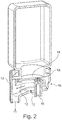
- the invention relates to a cartridge holder with a diluent, in particular a water inlet, a mixing chamber in which the diluent and a beverage and / or food substrate are mixed, and an outlet.
- Such cartridge receptacles are from the prior art, for example from EP 2 017 221 A1 and WO 2006/005401 A2 , known and are used to produce cold beverages, for example, using cartridges.
- good hygiene good mixing between the beverage and / or food substrate and the solvent, in particular water, which are mixed in the cartridge receptacle is also important.
- the output is solved with a cartridge holder with a diluent, in particular a water inlet, a mixing chamber in which the diluent and a beverage and / or food substrate are mixed, and an outlet, whereby the flow cross-section is initially expanded and then reduced again, drawn to the direction of flow of the diluent.
- a diluent in particular a water inlet, a mixing chamber in which the diluent and a beverage and / or food substrate are mixed, and an outlet, whereby the flow cross-section is initially expanded and then reduced again, drawn to the direction of flow of the diluent.
- the present invention relates to a cartridge receptacle which reversibly or irreversibly holds a cartridge, in particular partially.
- the cartridge has a cavity in which a beverage and / or food substance is located and which is hermetically sealed prior to the beverage and / or food production.
- the cartridge is then opened, in particular pierced, and the substrate runs / flows into a mixing chamber of the cartridge holder, which also has a solvent, in particular water inlet, which is mixed with the substrate in order to produce the finished drink or food which is also discharged from the cartridge holder through an outlet that is also provided on the cartridge holder Mixing chamber runs out.
- the volume flow of the solvent is generally much greater than the volume flow of the substrate.
- the flow cross-section i.e. the cross section, which is available for the flow of the liquid, in particular the solvent flow and / or the mixture of solvent and substrate, is now provided in such a way that it initially slows down and then accelerates the flow rate based on the flow direction of the solvent.
- the acceleration which is achieved by constricting the flow cross-section, takes place, if possible, after the solvent and the substrate have been mixed.
- the respective transition between the area with an enlarged flow cross-section and the areas with a narrowed flow cross-section is predetermined by the course of the wall of the mixing chamber.
- the wall can have a curved or stepped or angular course in the transition areas.
- the mixing chamber has a bulge.
- This bulge preferably protrudes from the circumference, in particular the lateral circumference, which extends between the two end faces of the cartridge receptacle.
- the bulge is preferably part of the mixing chamber.
- the circumference of the mixing chamber is preferably designed to be essentially circular and the bulge emerges from this circular shape. According to a particularly preferred embodiment of the present invention, the drainage of the finished drink or food is provided in the bulge.
- the cartridge receptacle has a fastening and / or securing ring.
- This fastening and / or locking ring preferably takes the cartridge, which is attached to the cartridge holder.
- the fastening and / or securing ring is preferably provided with a predetermined breaking point and / or predetermined deformation point on the mixing chamber. Before a drink or foodstuff is produced, this point is destroyed and / or deformed, in particular irreversibly deformed. This can be done, for example, by moving the cartridge and the cartridge holder relative to one another. As a result of the deformation and / or destruction, the cartridge holder can only be used once and / or the bond between the cartridge holder and the cartridge can no longer be released.
- At least one mixing element is preferably provided in the mixing chamber, which ensures that the solvent or the mixture of solvent and substrate is swirled.
- the mixing element is preferably provided as a bulge in the bottom.
- the mixing element is preferably designed in such a way that carbonic acid which is dissolved in the solvent is not or only slightly outgassed.
- the mixing element is preferably designed in such a way that it has only a low pressure loss.
- the cartridge receptacle preferably has a piercing means which perforates the membrane.
- This piercing means is designed, for example, as a mandrel that protrudes from the bottom of the mixing chamber.
- the piercing means preferably has at least one, preferably several indentations and / or bulges on its outer periphery, which serve as a drain for the substrate. The amount and size of the indentations and / or indentations depends preferably on the viscosity of the substrate.
- the piercing means preferably has a channel which ends in or in the region of the tip. A gas, in particular air or CO 2, can be blown into the cartridge through this channel in order to accelerate and / or dose the delivery of the substrate.
- the cartridge receptacle preferably has a mandrel guide, the piercing means being displaceably mounted within the mandrel guide, the piercing means between a retracted position in which the piercing means is spaced from the membrane and an extended position in which the piercing means pierces the membrane of the cartridge and protrudes into the cartridge, is displaceable.
- At least one side channel for guiding the beverage and / or food substrate in the direction of the mixing chamber when the membrane is pierced by the piercing means is preferably made in the outer wall of the piercing means.
- a compressed air line is particularly preferably integrated into the piercing means, with a compressed air connection for connection to a connection with a compressed air connection, particularly accessible from outside the cartridge receptacle, on a side of the piercing means facing away from the cartridge
- Compressed air source is formed and wherein a side of the piercing means facing the cartridge
- the inlet and the outlet are preferably provided at opposite ends of the cartridge receptacle.
- the piercing means is particularly preferably provided in alignment with the inlet and the outlet.
- the outlet is movable, in particular pivotable, provided on the mixing chamber or has a means with which the outlet is aligned, in particular in the direction of the side wall of the vessel that receives the finished drink or food, can be directed.
- This embodiment is particularly advantageous for beverages or foods that tend to foam.
- the outlet can be moved manually or by motor. In the event that the cartridge has an identification, the pivoting can take place automatically after the dispenser has recognized the cartridge.
- Another object of the present invention is a system comprising the cartridge receptacle according to the invention or preferably, on / in which a cartridge is provided which has a wall area, at one end of which is connected a connection area which is closed, in particular with a membrane (14) is and at the opposite end of which a floor area is optionally provided, the wall area and optionally the floor area spanning a cavity which receives a beverage and / or food substrate.
- the cartridge is preferably made of plastic, in particular by a molding and / or a blow molding process.
- the cartridge has a side wall which, for example, has a round, rectangular, square, conical or oval cross section.
- a base is generally provided, in particular in one piece.
- the side wall and, if appropriate, the bottom area span a cavity in which a beverage and / or food substrate, in particular in liquid form, is provided.
- a connection area is provided with which the cartridge with the cartridge receptacle is connected.
- This cartridge receptacle can be part of a dispenser or a component separate from the dispenser.
- connection area is preferably provided in such a way that it has a flange.
- the flange protrudes from the connection area and preferably protrudes at an angle, particularly preferably a right angle, from a wall area of the connection area.
- the flange is preferably oriented horizontally.
- the flange is made of solid material, i. not made hollow.
- the flange is preferably provided with a positioning and / or covering means.
- the positioning means ensures that the cartridge can only be arranged on the dispenser and / or on the cartridge receptacle in a specific position, in particular at a specific angle of rotation, in particular in relation to the longitudinal center axis of the cartridge.
- the covering means covers an area, in particular an area, through which the finished drink or food flows off.
- the positioning means and the covering means are preferably identical.
- the positioning means and / or covering means is preferably an indentation and / or bulge which protrudes from the flange, in particular its circumference.
- the positioning means and / or covering means are preferably provided in one piece with the flange.
- the positioning means and / or covering means is designed as a nose which is molded onto the periphery of the flange at one point.
- the thickness of the positioning means and / or covering means corresponds at least essentially to the thickness of the flange.
- a neck is provided between the wall area and the connecting area.
- This neck can for example have a round cross section.
- the neck represents the wall area of the connection area.
- the flange preferably adjoins the neck at right angles.
- the membrane which closes the cartridge, in particular hermetically, before it is used, is preferably provided, in particular sealed, on the flange, in particular its end face.
- the flange in particular its end face, can have a bead, in particular a circular bead, which interacts with the sealing tool during sealing.
- the outer circumference of the membrane is less than the outer circumference of the flange.
- a fastening means is preferably provided in the wall area and / or in the area of the neck. With this fastening means, the cartridge can be connected to a dispenser.
- the fastening means can, for example, be a groove into which a fastening means on the dispenser engages.
- the cartridge receptacle can be permanently connected to the cartridge or it can be an exchangeable part that is removed from the cartridge after use and connected to a new cartridge.
- the cartridge holder is preferably made of plastic, in particular by injection molding.
- the cartridge receptacle is preferably connected to a dispenser.
- the covering means which is provided on the flange of the cartridge preferably covers the drain from the cartridge receptacle.
- the flange on the cartridge in particular its circumference, preferably acts in a sealing manner with the cartridge receptacle.
- the periphery of the flange can, for example, engage in a groove in the cartridge receptacle.
- This flange / groove connection can also serve as a frictional connection in order to prevent the cartridge from being displaced relative to the cartridge receptacle during beverage or food production and the connection between the cartridge and the cartridge receptacle becoming leaky.
- the cartridge and the cartridge holder are.
- the membrane before the membrane is pierced, provided so that they can be displaced longitudinally with respect to one another. As a result of this longitudinal displacement, the piercing means can then be brought into engagement with the membrane and pierce it.
- the cartridge and the cartridge holder are preferably connected to one another in a rotationally fixed manner.
- the piercing means preferably has a channel. A gas can be pressed into the cartridge through this channel, which gas presses the beverage and / or food substrate out of the cartridge, in particular into the mixing space of the cartridge receptacle.
- FIGS 1 - 4 show a first embodiment of the system according to the invention that consists of a cartridge 1 and a cartridge receptacle 10.
- the cartridge is preferably made of a plastic material, for example by spraying or injection molding or by a blow molding technique.
- the cartridge has a wall area 6, which is square in the present case, at one end of which, here the upper end, is a base area 7.
- the wall area 6 and the bottom area 7 delimit a cavity in which the beverage and / or food substrate, in particular a concentrate, is located, with which a beverage or food can be produced.
- a connection area 4 is provided, which in the present case has a neck 3 and a flange 5.
- the cavity of the cartridge is hermetically sealed by a closure 14, here a membrane.
- the membrane 14, in particular a plastic film, is preferably materially bonded, in particular through Sealing connected to the flange.
- the cartridge With the connection area, the cartridge is connected to a cartridge holder.
- a positioning and / or covering means 8 is provided on the flange 5, which in the present case is provided as a bulge, in particular as a nose-shaped bulge.
- the nose is formed in one piece on the flange here.
- the system such as in particular the Figures 1 b) and c) can be removed, a cartridge holder 10.
- This cartridge holder has a solvent, in particular water, inlet 15 (cf.
- Figure 2 and a mixing chamber 13 in which the solvent and the beverage and / or food substrate are mixed.
- the direction of flow of the mixture is in Figure 1 c) represented by arrow 12.
- the finished drink / food leaves the mixing chamber through the outlet 11 and is collected in a container, for example a glass.
- the cartridge receptacle has a piercing means 16, here a mandrel 16, which, as in particular based on Figure 3 can be seen, the membrane, which is sealed to the flange area of the cartridge, pierces so that the beverage or food substrate can flow into the flow chamber 13, in particular along the outer surface of the mandrel, which is preferably provided with drainage channels 17 on its outer side .
- Figure 2 shows the system before the piercing means 16 comes into engagement with the membrane 14.
- the cartridge and / or the cartridge receptacle are displaced relative and longitudinally to one another, so that the mandrel 16 penetrates the membrane 14, which is particularly evident from FIG Figure 3 c) can be clearly seen.
- the channels 17 through which the substrate flows into the mixing chamber can also be recognized particularly well in this figure.
- the flow of the substrate into the mixing chamber can be accelerated and specifically controlled by gas which is pressed into the cartridge through a channel 18 in the piercing spike 16.
- the pressure in the cartridge can be adapted to the volume flow of the solvent.
- the flange 5 of the cartridge 1 cooperates in a sealing manner with the cartridge receptacle and thereby ensures that the liquid only leaves the mixing chamber through the drain 5.
- the bulge 8 in the present case is not only a positioning means, but also covers the drain 11 in the cartridge receptacle in a particularly sealing manner.
- the flange 8 and the bulge 8 provided thereon can cooperate with their end face and / or with their circumference in a sealing manner with corresponding surfaces of the cartridge receptacle.
- the Figures 5 - 8 show a further embodiment of the system according to the invention.
- the cartridge in its connection area, in addition to the flange 5, also has a fastening means 20 which connects the cartridge 1 to the cartridge receptacle 10.
- the wall area 6 has an indentation 24 which allows longitudinal displacement between the cartridge and the cartridge receptacle and possibly a dispenser and which also represents a guide for the cartridge.
- the cartridge receptacle in the present case has a fastening or securing ring 21 which is connected to the mixing chamber 13 by means of deformation and / or predetermined breaking points 22.
- This ring 21 acts in a force-locking manner with the fastening means 20, for example here a collar 20 which is provided on the cartridge.
- the cartridge receptacle 10 has further piercing means 16 in addition to the mandrel 18. A gas is pressed into the cartridge through the mandrel 18, which gas presses the substrate out of the cartridge.
- the opening means 16 cut, here angled cuts, into the membrane, which then form tabs which are pressed down under the pressure of the substrate and thus enable easier drainage of the substrate.
- a piercing means 16 may also suffice, or that it is also possible to pierce the membrane and drain the substrate as on the basis of FIG Figures 1 - 4 explained to be used in the present case.
- the opening means 16, 18 here can also be applied to the embodiment according to FIGS Figures 1 to 4 be transmitted.
- Figure 5 shows the system before piercing.
- Figure 6 shows the system after the membrane has been pierced.
- the desired deformation or predetermined breaking points 22 are deformed or destroyed in such a way that the cartridge can move together with the ring 21 in the direction of the mixing chamber 13.
- the membrane 14 is perforated and the substrate can flow from the cartridge into the mixing chamber, in which it is mixed with a solvent that flows through the inlet 15 is dosed into the mixing chamber, mixed and leaves the mixing chamber through the outlet 11.
- Figure 9 shows a fastening means here a groove 25 in the wall area of the cartridge.
- a fastening means 26, with which the cartridge is fastened to a dispender, can engage in this groove.
- the Figures 10 and 11 each show the mixing chamber in plan view.
- the mixing chamber 13 is provided with a mixing element 28, which in the present case consists of several components.
- the components are circular ring segment-shaped, whereby the diameter of the circular rings can differ.
- the embodiment according to Figure 11 are the components angles.
- the mixing elements 28 are preferably designed in such a way that, on the one hand, they mix the substrate and the solvent well with one another, but on the other hand only the lowest possible pressure loss occurs.
- Figure 12 on the right is the system consisting of the cartridge 1 and the cartridge holder 10.
- the view here is from the direction of the drain.
- the left representation of Figure 12 shows a holder 29 with which the system 1, 10 is held on a dispenser.
- the holder 29 has a recess into which the bottom of the mixing chamber protrudes at least partially.
- the bracket serves as a support for the system.
- Below the holder 29 there is a container into which the finished drink or food runs.
- the holder has a guide 30 which interacts positively with the cartridge receptacle 10 and secures it against lateral slipping and / or twisting relative to the holder 29.
- the guide is provided at a distance from the recess.
- the specialist understands that the function of securing against slipping and / or twisting can also be taken over by a form fit between the recess and the bottom of the cartridge holder.
- a connection for the solvent adjoins the recess, but this connection is preferably not part of the holder.
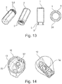
- FIG Figure 13 four images of a cartridge 1 according to a further exemplary embodiment of the present invention are shown.
- the cartridge 1 and the associated system of cartridge 2 and cartridge holder 10 (illustrated in FIG Figure 14 ) are similar in their functionality to the one based on Figures 1 to 4 illustrated system according to the first embodiment of the present invention.
- the cartridge 1 shown has two flanges 5. Both flanges 5 are used to fasten the cartridge receptacle 10 to the cartridge 1.
- the membrane 14 is also sealed on the outer flange 5.
- the cross-section (perpendicular to the longitudinal axis of the cartridge 1) of both flanges 5 has an essentially round circumference, a straight circumferential area 31 being provided on one side.
- the circumference runs as an almost straight line (can be seen on the underside of the flange 5 in the right figure in Figure 13 ), while the periphery of the flange 5 extends outside the rectilinear peripheral region 31 as a curved line.
- the rectilinear circumferential area 31 serves as a positioning means, whereby the orientation of the cartridge 1 with respect to the cartridge receptacle 10 is determined.
- the matching cartridge holder 10 can be seen. It can be seen that, in the further embodiment, the circumference of the cartridge receptacle 10 is one to the contour of the two in Figure 10 Flanges 5 shown has a corresponding shape, so that the cartridge 2 and cartridge holder 10 can only be connected to one another in a certain orientation.
- the straight circumferential area 31 thus serves as a protection against rotation. This advantageously also defines the area of the cartridge 1 in which the gas is pressed into the cavity.
- a mandrel guide 32 is arranged inside the mixing chamber 13, in which the mandrel 16 (also referred to as a piercing means) is movably guided.
- the perforation of the membrane 14 is not brought about by a relative movement between the cartridge 1 and the cartridge receptacle 10, but the mandrel 16 is movably guided in the cartridge receptacle 10 which is fixedly fixed relative to the cartridge 1.
- the mandrel 16 can be transferred from a retracted position (corresponds above all to the initial state of the system), in which the mandrel 16 is spaced from the membrane 14, into an extended position in which the mandrel 16 enters the cavity of the cartridge 1 protrudes and thereby perforates the membrane 14.
- the cartridge 1 is therefore open and the beverage and / or food substrate can pass through drainage channels 17 in the outer surface of the mandrel 16 past the membrane 14 and into the mixing chamber 13.
- a latching strip 33 is also provided which, for fastening the cartridge 1 to the cartridge receptacle 10, engages around one of the two flanges 5 in a form-fitting and / or force-fitting manner. In this way, a relative movement between cartridge 1 and cartridge holder 10 is prevented.
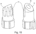
- Figure 14 is a schematic view of a mandrel 16 shown, which in the in Figure 13 mandrel guide 32 shown is guided.
- the mandrel 16 has an inner compressed air line 34, which serves as a gas inlet 18, as well as the outer drainage channels 17 through which the substrate can flow past the membrane 14 pierced by means of the mandrel 16 into the mixing chamber 13.
- a compressed air connection of the compressed air line 34 which is accessible from outside the cartridge receptacle 10, is formed for connection to a compressed air source, with a compressed air outlet of the compressed air line 34 for blowing the compressed air into the cartridge 1 is formed.
Description
Die Erfindung betrifft eine Kartuschenaufnahme mit einem Verdünnungsmittel- insbesondere Wasserzulauf, einer Mischkammer in der das Verdünnungsmittel und ein Getränke- und/oder Lebensmittelsubstrat gemischt werden und einem Ablauf.The invention relates to a cartridge holder with a diluent, in particular a water inlet, a mixing chamber in which the diluent and a beverage and / or food substrate are mixed, and an outlet.
Derartige Kartuschenaufnahmen sind aus dem Stand der Technik, beispielsweise aus
Es war deshalb die Aufgabe der vorliegenden Erfindung eine Kartuschenaufnahme zur Verfügung zu stellen, die diesen Anforderungen gerecht wird.It was therefore the object of the present invention to provide a cartridge holder which meets these requirements.
Gelöst wird die Ausgabe mit einer Kartuschenaufnahme mit einem Verdünnungsmittelinsbesondere Wasserzulauf, einer Mischkammer in der das Verdünnungsmittel und ein Getränke- und/oder Lebensmittelsubstrat gemischt werden und einem Ablauf, wobei sich gezogen auf die Strömungsrichtung des Verdünnungsmittels der Strömungsquerschnitt zunächst erweitert und dann wieder vermindert.The output is solved with a cartridge holder with a diluent, in particular a water inlet, a mixing chamber in which the diluent and a beverage and / or food substrate are mixed, and an outlet, whereby the flow cross-section is initially expanded and then reduced again, drawn to the direction of flow of the diluent.
Die zu diesem Gegenstand der vorliegenden Erfindung gemachten Ausführungen gelten für die anderen Gegenstände der vorliegenden Erfindung gleichermaßen und umgekehrt.The statements made in relation to this subject matter of the present invention apply equally to the other subjects of the present invention and vice versa.
Die vorliegende Erfindung betrifft eine Kartuschenaufnahme, die reversibel oder irreversibel eine Kartusche insbesondere teilweise aufnimmt. Die Kartusche hat einen Hohlraum, in dem sich eine Getränke- und/oder Lebensmittelsubstanz befindet und die vor der Getränke- und/oder Lebensmittelherstellung hermetisch verschlossen ist. Zur Herstellung des Getränks und/oder Lebensmittels wird die Kartusche dann geöffnet, insbesondere aufgestochen, und das Substrat läuft/strömt in eine Mischkammer der Kartuschenaufnahme, die auch über einen Lösungsmittel-, insbesondere Wasserzulauf, verfügt, das mit dem Substrat gemischt wird, um das fertige Getränk oder Lebensmittel zu erzeugen, das durch einen ebenfalls an der Kartuschenaufnahme vorgesehenen Ablauf aus der Mischkammer rausläuft. Der Volumenstrom des Lösungsmittels ist dabei in der Regel wesentlich größer als der Volumenstrom des Substrats.The present invention relates to a cartridge receptacle which reversibly or irreversibly holds a cartridge, in particular partially. The cartridge has a cavity in which a beverage and / or food substance is located and which is hermetically sealed prior to the beverage and / or food production. To produce the drink and / or foodstuff, the cartridge is then opened, in particular pierced, and the substrate runs / flows into a mixing chamber of the cartridge holder, which also has a solvent, in particular water inlet, which is mixed with the substrate in order to produce the finished drink or food which is also discharged from the cartridge holder through an outlet that is also provided on the cartridge holder Mixing chamber runs out. The volume flow of the solvent is generally much greater than the volume flow of the substrate.
Erfindungsgemäß ist der Strömungsquerschnitt, d.h. der Querschnitt, der für Strömung der Flüssigkeit, insbesondere des Lösungsmittelstroms und/oder des Gemischs aus Lösungsmittel und Substrat zur Verfügung steht, nun so vorgesehen, dass er sich bezogen auf die Strömungsrichtung des Lösungsmittels die Strömungsgeschwindigkeit zunächst verlangsamt und dann wieder beschleunigt. Die Beschleunigung, die durch eine Strömungsquerschnittsverengung erreicht wird, findet möglichst statt, nachdem das Lösungsmittel und das Substrat vermischt worden sind.According to the invention the flow cross-section, i.e. the cross section, which is available for the flow of the liquid, in particular the solvent flow and / or the mixture of solvent and substrate, is now provided in such a way that it initially slows down and then accelerates the flow rate based on the flow direction of the solvent. The acceleration, which is achieved by constricting the flow cross-section, takes place, if possible, after the solvent and the substrate have been mixed.
Der jeweilige Übergang zwischen dem Bereich mit erweitertem Strömungsquerschnitt und den Bereichen mit verengtem Strömungsquerschnitt wird durch den Verlauf der Wandung der Mischkammer vorgegeben. Die Wandung kann hierfür einen gekrümmten oder abgestuften bzw. eckigen Verlauf in den Übergangsbereichen aufweisen.The respective transition between the area with an enlarged flow cross-section and the areas with a narrowed flow cross-section is predetermined by the course of the wall of the mixing chamber. For this purpose, the wall can have a curved or stepped or angular course in the transition areas.
Gemäß einem weiteren bevorzugten oder erfindungsgemäßen Gegenstand der vorliegenden Erfindung weist die Mischkammer eine Ausbuchtung auf.According to a further preferred or inventive subject matter of the present invention, the mixing chamber has a bulge.
Die zu diesem Gegenstand der vorliegenden Erfindung gemachten Ausführungen gelten für die anderen Gegenstände der vorliegenden Erfindung gleichermaßen und umgekehrt.The statements made in relation to this subject matter of the present invention apply equally to the other subjects of the present invention and vice versa.
Diese Ausbuchtung ragt vorzugsweise aus dem Umfang, insbesondere dem seitlichen Umfang, der sich zwischen den beiden Stirnseiten der Kartuschenaufnahme erstreckt heraus. Vorzugsweise ist die Ausbuchtung Teil der Mischkammer. Vorzugsweise ist der Umfang der Mischkammer im wesentlichen kreisförmig gestaltet und die Ausbuchtung rang aus dieser Kreisform heraus. Gemäß einer besonders bevorzugten Ausführungsform der vorliegenden Erfindung ist der Ablauf des fertiggestellten Getränks oder Lebensmittels in der Ausbuchtung vorgesehen.This bulge preferably protrudes from the circumference, in particular the lateral circumference, which extends between the two end faces of the cartridge receptacle. The bulge is preferably part of the mixing chamber. The circumference of the mixing chamber is preferably designed to be essentially circular and the bulge emerges from this circular shape. According to a particularly preferred embodiment of the present invention, the drainage of the finished drink or food is provided in the bulge.
Gemäß noch einem bevorzugten oder erfindungsgemäßen Gegenstand der vorliegenden Erfindung weist die Kartuschenaufnahme einen Befestigungs- und/oder Sicherungsring aufweist. Dieser Befestigungs- und/oder Sicherungsring nimmt vorzugsweise die Kartusche, die an der Kartuschenaufnahme befestigt wird, auf. Vorzugsweise ist der Befestigungs- und/oder Sicherungsring mit einer Sollbruch- und/oder Solldeformationsstelle an der Mischkammer vorgesehen. Vor der Herstellung eines Getränks oder Lebensmittels wird diese Stelle zerstört und oder verformt, insbesondere irreversibel verformt. Dies kann beispielsweise durch eine Bewegung der Kartusche und der Kartuschenaufnahme relativ zueinander erfolgen. Durch die Deformation und/oder Zerstörung kann die Kartuschenaufnahme nur einmal benutzt werden und/oder der Verbund zwischen der Kartuschenaufnahme und der Kartusche kann nicht mehr gelöst werden.According to yet another preferred or inventive subject matter of the present invention, the cartridge receptacle has a fastening and / or securing ring. This fastening and / or locking ring preferably takes the cartridge, which is attached to the cartridge holder. The fastening and / or securing ring is preferably provided with a predetermined breaking point and / or predetermined deformation point on the mixing chamber. Before a drink or foodstuff is produced, this point is destroyed and / or deformed, in particular irreversibly deformed. This can be done, for example, by moving the cartridge and the cartridge holder relative to one another. As a result of the deformation and / or destruction, the cartridge holder can only be used once and / or the bond between the cartridge holder and the cartridge can no longer be released.
Vorzugsweise ist in der Mischkammer mindestens ein Mischelement vorgesehen, das für eine Verwirbelung des Lösemittels oder des Gemischs von Lösemittel und Substrat sorgt. Vorzugsweise ist das Mischelement als Ausbuchtung im Boden vorgesehen. Vorzugsweise ist das Mischelement so gestaltet, dass Kohlensäure, die in dem Lösemittel gelöst ist, nicht oder nur geringfügig ausgast. Vorzugsweise ist das Mischelement so gestaltet, das es nur einen geringen Druckverlust aufweist.At least one mixing element is preferably provided in the mixing chamber, which ensures that the solvent or the mixture of solvent and substrate is swirled. The mixing element is preferably provided as a bulge in the bottom. The mixing element is preferably designed in such a way that carbonic acid which is dissolved in the solvent is not or only slightly outgassed. The mixing element is preferably designed in such a way that it has only a low pressure loss.
Vorzugsweise weist die Kartuschenaufnahme ein Aufstechmittel, das die Membran perforiert, auf. Dieses Aufstechmittel ist beispielsweise als Dorn gestaltet, der aus dem Boden der Mischkammer ragt. Vorzugsweise weist das Aufstechmittel an seinem äußeren Umfang mindestens eine, vorzugsweise mehrere Ein- und/oder Ausbuchtungen auf, die als Ablauf für das Substrat dienen. Die Menge und die Größe der Ein- und/oder Ausbuchtungen hängt vorzugsweise von der Viskosität des Substrats ab. Vorzugsweise weist das Aufstechmittel einen Kanal auf, der in oder im Bereich der Spitze endet. Durch diesen Kanal kann ein Gas, insbesondere Luft oder CO2 in die Kartusche geblasen werden, um die Abgabe des Substrats zu beschleunigen und/oder zu dosieren.The cartridge receptacle preferably has a piercing means which perforates the membrane. This piercing means is designed, for example, as a mandrel that protrudes from the bottom of the mixing chamber. The piercing means preferably has at least one, preferably several indentations and / or bulges on its outer periphery, which serve as a drain for the substrate. The amount and size of the indentations and / or indentations depends preferably on the viscosity of the substrate. The piercing means preferably has a channel which ends in or in the region of the tip. A gas, in particular air or CO 2, can be blown into the cartridge through this channel in order to accelerate and / or dose the delivery of the substrate.
Vorzugsweise weist die Kartuschenaufnahme eine Dornführung auf, wobei das Aufstechmittel verschiebbar innerhalb der Dornführung gelagert ist, wobei das Aufstechmittel zwischen einer eingefahrenen Position, in welcher das Aufstechmittel von der Membran beabstandet ist, und einer ausgefahrenen Position, in welcher das Aufstechmittel die Membran der Kartusche durchsticht und bis in die Kartusche ragt, verschiebbar ist. In die Außenwandung des Aufstechmittels ist vorzugsweise wenigstens ein Seitenkanal zum Leiten des Getränke- und/oder Lebensmittelsubstrats in Richtung der Mischkammer, wenn die Membran von dem Aufstechmittel durchstochen ist, eingebracht. Ferner ist in das Aufstechmittel besonders bevorzugt eine Druckluftleitung integriert, wobei an einer der Kartusche abgewandten Seite des Aufstechmittels ein, insbesondere von außerhalb der Kartuschenaufnahme zugänglicher Druckluftanschluss zur Verbindung mit einerThe cartridge receptacle preferably has a mandrel guide, the piercing means being displaceably mounted within the mandrel guide, the piercing means between a retracted position in which the piercing means is spaced from the membrane and an extended position in which the piercing means pierces the membrane of the cartridge and protrudes into the cartridge, is displaceable. At least one side channel for guiding the beverage and / or food substrate in the direction of the mixing chamber when the membrane is pierced by the piercing means is preferably made in the outer wall of the piercing means. Furthermore, a compressed air line is particularly preferably integrated into the piercing means, with a compressed air connection for connection to a connection with a compressed air connection, particularly accessible from outside the cartridge receptacle, on a side of the piercing means facing away from the cartridge
Druckluftquelle ausgebildet ist und wobei an einer der Kartusche zugewandten Seite des Aufstechmittels einCompressed air source is formed and wherein a side of the piercing means facing the cartridge
Vorzugsweise sind der Zulauf und der Ablauf an gegenüberliegenden Enden der Kartuschenaufnahme vorgesehen. Besonders bevorzugt ist das Aufstechmittel in einer Flucht mit dem Zulauf und dem Ablauf vorgesehen.The inlet and the outlet are preferably provided at opposite ends of the cartridge receptacle. The piercing means is particularly preferably provided in alignment with the inlet and the outlet.
Gemäß einem weiteren bevorzugten oder erfindungsgemäßen Gegenstand der vorliegenden Erfindung ist der Auslauf beweglich, insbesondere schwenkbar, an der Mischkammer vorgesehen oder weist ein Mittel auf, mit dem der Auslauf ausgerichtet, insbesondere in Richtung der Seitenwand des Gefäßes, das das fertiggestellte Getränk oder Lebensmittel aufnimmt, gerichtet werden kann. Diese Ausführungsform ist insbesondere bei Getränken oder Lebensmittels, die zu Schaumbildung neigen vorteilhaft. Das Bewegen des Auslaufs kann manuell oder motorisch erfolgen. Für den Fall, dass die Kartusche eine Identifikation aufweist, kann das Schwenken automatisch erfolgen, nachdem der Dispenser die Kartusche erkannt hat.According to a further preferred or inventive subject matter of the present invention, the outlet is movable, in particular pivotable, provided on the mixing chamber or has a means with which the outlet is aligned, in particular in the direction of the side wall of the vessel that receives the finished drink or food, can be directed. This embodiment is particularly advantageous for beverages or foods that tend to foam. The outlet can be moved manually or by motor. In the event that the cartridge has an identification, the pivoting can take place automatically after the dispenser has recognized the cartridge.
Noch ein Gegenstand der vorliegenden Erfindung ist ein System aufweisend die erfindungsgemäße oder bevorzugt Kartuschenaufnahme, an/in der eine Kartusche vorgesehen ist, die einen Wandbereich aufweist, an dessen einem Ende sich ein Verbindungsbereich anschließt, der, insbesondere mit einer Membran (14), verschlossen ist und an dessen gegenüberliegendem Ende gegebenenfalls ein Bodenbereich vorgesehen ist, wobei der Wandbereich und gegebenenfalls der Bodenbereich einen Hohlraum aufspannen, der ein Getränke- und/oder Lebensmittelsubstrat aufnimmt.Another object of the present invention is a system comprising the cartridge receptacle according to the invention or preferably, on / in which a cartridge is provided which has a wall area, at one end of which is connected a connection area which is closed, in particular with a membrane (14) is and at the opposite end of which a floor area is optionally provided, the wall area and optionally the floor area spanning a cavity which receives a beverage and / or food substrate.
Die zu diesem Gegenstand der vorliegenden Erfindung gemachten Ausführungen gelten für die anderen Gegenstände der vorliegenden Erfindung gleichermaßen und umgekehrt.The statements made in relation to this subject matter of the present invention apply equally to the other subjects of the present invention and vice versa.
Die Kartusche wird vorzugsweise aus Kunststoff, insbesondere durch ein Moulding- und/oder ein Blasverfahren hergestellt. Die Kartusche weist eine Seitenwand auf, die beispielsweise einen runden, rechteckigen, quadratischen, konischen oder ovalen Querschnitt aufweist. An einem Ende der Seitenwand ist in der Regel ein Boden, insbesondere einstückig vorgesehen. Die Seitenwand und gegebenenfalls der Bodenbereich spannen einen Hohlraum auf, in dem ein Getränke- und/oder Lebensmittelsubstrat, insbesondere in flüssiger Form vorgesehen ist. An dem anderen Ende des Wandbereichs ist ein Verbindungsbereich vorgesehen, mit dem die Kartusche mit der Kartuschenaufnahme verbunden wird. Diese Kartuschenaufnahme kann Teil eines Dispensers oder ein vom Dispenser separates Bauteil sein.The cartridge is preferably made of plastic, in particular by a molding and / or a blow molding process. The cartridge has a side wall which, for example, has a round, rectangular, square, conical or oval cross section. At one end of the side wall, a base is generally provided, in particular in one piece. The side wall and, if appropriate, the bottom area span a cavity in which a beverage and / or food substrate, in particular in liquid form, is provided. At the other end of the wall area, a connection area is provided with which the cartridge with the cartridge receptacle is connected. This cartridge receptacle can be part of a dispenser or a component separate from the dispenser.
Vorzugsweise ist der Verbindungsbereich so vorgesehen, dass er einen Flansch aufweist. Der Flansch steht aus dem Verbindungsbereich hervor und steht vorzugsweise in einem Winkel, besonders bevorzugt einem rechten Winkel von einem Wandbereich des Verbindungsbereichs ab. Zur Herstellung des Getränks oder Lebensmittels ist der Flansch vorzugsweise horizontal ausgerichtet. Vorzugsweise ist der Flansch aus Vollmaterial, d.h. nicht hohl gefertigt.The connection area is preferably provided in such a way that it has a flange. The flange protrudes from the connection area and preferably protrudes at an angle, particularly preferably a right angle, from a wall area of the connection area. To produce the beverage or food, the flange is preferably oriented horizontally. Preferably the flange is made of solid material, i. not made hollow.
Weiterhin bevorzugt ist der Flansch mit einem Positionier- und oder Abdeckmittel versehen. Das Positioniermittel stellt sicher, dass die Kartusche nur in einer bestimmten Position, insbesondere in einem bestimmten Drehwinkel, insbesondere Bezogen auf die Längsmittelachse der Kartusche an dem Dispenser und/oder an der Kartuschenaufnahme angeordnet werden kann. Das Abdeckmittel deckt einen Bereich, insbesondere einen Bereich, durch den das fertig gestellte Getränk oder Lebensmittel fließt ab. Vorzugsweise sind das Positioniermittel und das Abdeckmittel identisch.Furthermore, the flange is preferably provided with a positioning and / or covering means. The positioning means ensures that the cartridge can only be arranged on the dispenser and / or on the cartridge receptacle in a specific position, in particular at a specific angle of rotation, in particular in relation to the longitudinal center axis of the cartridge. The covering means covers an area, in particular an area, through which the finished drink or food flows off. The positioning means and the covering means are preferably identical.
Vorzugsweise ist das Positioniermittel und/oder Abdeckmittel eine Ein- und/oder Ausbuchtung, die aus dem Flansch, insbesondere dessen Umfang hervorsteht. Vorzugsweise ist das Positioniermittel und/oder Abdeckmittel einstückig mit dem Flansch vorgesehen. Beispielsweise ist das Positioniermittel und/oder Abdeckmittel als Nase ausgebildet, die an einer Stelle an den Umfang des Flanschs angeformt ist. Die Dicke des Positioniermittels und/oder Abdeckmittels entspricht dabei zumindest im wesentlichen der Dicke des Flanschs.The positioning means and / or covering means is preferably an indentation and / or bulge which protrudes from the flange, in particular its circumference. The positioning means and / or covering means are preferably provided in one piece with the flange. For example, the positioning means and / or covering means is designed as a nose which is molded onto the periphery of the flange at one point. The thickness of the positioning means and / or covering means corresponds at least essentially to the thickness of the flange.
Gemäß einer bevorzugten Ausführungsform ist zwischen dem Wandbereich und dem Verbindungsbereich ein Hals vorgesehen. Dieser Hals kann beispielsweise einen runden Querschnitt aufweisen. Der Hals stellt den Wandbereich des Verbindungsbereichs dar. Der Flansch schließt sich vorzugsweise rechtwinklig an den Hals an.According to a preferred embodiment, a neck is provided between the wall area and the connecting area. This neck can for example have a round cross section. The neck represents the wall area of the connection area. The flange preferably adjoins the neck at right angles.
Vorzugsweise ist die Membran, die die Kartusche vor deren Gebrauch, insbesondere hermetisch verschließt, an dem Flansch, insbesondere dessen Stirnfläche, vorgesehen, insbesondere gesiegelt. Dafür kann der Flansch, insbesondere dessen Stirnfläche eine Wulst, insbesondere eine kreisringförmige Wulst aufweisen, die beim Siegeln mit dem Siegelwerkzeug zusammenwirkt. Vorzugsweise ist der äußere Umfang der Membran geringer als der äußere Umfang des Flansches.The membrane, which closes the cartridge, in particular hermetically, before it is used, is preferably provided, in particular sealed, on the flange, in particular its end face. For this purpose, the flange, in particular its end face, can have a bead, in particular a circular bead, which interacts with the sealing tool during sealing. Preferably the outer circumference of the membrane is less than the outer circumference of the flange.
Vorzugsweise ist im Wandbereich und/oder im Bereich des Halses ein Befestigungsmittel vorgesehen ist. Mit diesem Befestigungsmittel kann die Kartusche mit einem Dispenser verbunden werden. Das Befestigungsmittel kann beispielsweise eine Nut sein, in die ein Befestigungsmittel an dem Dispenser eingreift.A fastening means is preferably provided in the wall area and / or in the area of the neck. With this fastening means, the cartridge can be connected to a dispenser. The fastening means can, for example, be a groove into which a fastening means on the dispenser engages.
Die Kartuschenaufnahme kann fest mit der Kartusche verbunden oder ein Austauschteil sein, das nach dem Gebrauch der Kartusche von dieser entfernt und mit einer neuen Kartusche verbunden wird. Vorzugsweise ist die Kartuschenaufnahme aus Kunststoff, insbesondere im Spritzguss gefertigt. Vorzugsweise wird die Kartuschenaufnahme mit einem Dispenser verbunden.The cartridge receptacle can be permanently connected to the cartridge or it can be an exchangeable part that is removed from the cartridge after use and connected to a new cartridge. The cartridge holder is preferably made of plastic, in particular by injection molding. The cartridge receptacle is preferably connected to a dispenser.
Vorzugsweise deckt das Abdeckmittel, das an dem Flansch der Kartusche vorgesehen ist den Ablauf den Kartuschenaufnahme ab.The covering means which is provided on the flange of the cartridge preferably covers the drain from the cartridge receptacle.
Vorzugsweise wirkt der Flansch an der Kartusche, insbesondere deren Umfang dichtend mit der Kartuschenaufnahme zusammen. Dafür kann der Umfang des Flansches beispielsweise in eine Nut in der Kartuschenaufnahme eingreifen. Diese Flansch/Nut-Verbindung kann auch als Kraftschluss dienen, um zu verhindern, dass sich die Kartusche relativ zu der Kartuschenaufnahme während der Getränke- oder Lebensmittelherstellung verschiebt und die Verbindung zwischen Kartusche und Kartuschenaufnahme undicht wird.The flange on the cartridge, in particular its circumference, preferably acts in a sealing manner with the cartridge receptacle. For this purpose, the periphery of the flange can, for example, engage in a groove in the cartridge receptacle. This flange / groove connection can also serve as a frictional connection in order to prevent the cartridge from being displaced relative to the cartridge receptacle during beverage or food production and the connection between the cartridge and the cartridge receptacle becoming leaky.
Gemäß einer bevorzugten Ausführungsform sind die Kartusche und die Kartuschenaufnahme. Insbesondere bevor die Membrane angestochen wird, längsverschieblich zueinander vorgesehen. Durch diese Längsverschiebung kann das Aufstechmittel dann mit der Membrane in Eingriff gebracht werden und diese durchstechen.According to a preferred embodiment, the cartridge and the cartridge holder are. In particular, before the membrane is pierced, provided so that they can be displaced longitudinally with respect to one another. As a result of this longitudinal displacement, the piercing means can then be brought into engagement with the membrane and pierce it.
Vorzugsweise sind die Kartusche und die Kartuschenaufnahme drehfest miteinander verbunden.The cartridge and the cartridge holder are preferably connected to one another in a rotationally fixed manner.
Vorzugsweise weist das Aufstechmittel einen Kanal auf. Durch diesen Kanal kann ein Gas in die Kartusche gedrückt werden, das das Getränke- und/oder Lebensmittelsubstrat aus der Kartusche insbesondere in den Mischraum der Kartuschenaufnahme drückt.The piercing means preferably has a channel. A gas can be pressed into the cartridge through this channel, which gas presses the beverage and / or food substrate out of the cartridge, in particular into the mixing space of the cartridge receptacle.
Im folgendem wird die Erfindung anhand der
- Figuren 1 - 4
- zeigen eine erste Ausführungsform des erfindungsgemäßen Systems.
- Figuren 5 - 8
- zeigen noch eine Ausführungsform des erfindungsgemäßen Systems.
Figur 9- zeigt eine Ausführungsform mit einem Befestigungsmittel.
Figuren 10 und 11- zeigen zwei Beispiele von Mischelementen
Figur 12- zeigt die Halterung für die Kartuschenaufnahme an dem Dispenser
Figur 13- zeigt eine Kartusche eines Systems gemäß einer weiteren Ausführungsform der vorliegenden Erfindung
Figur 14- zeigt eine Kartuschenaufnahme des Systems gemäß der weiteren Ausführungsform der vorliegenden Erfindung
Figur 15- zeigt einen Dorn der Kartuschenaufnahme gemäß der weiteren Ausführungsform der vorliegenden Erfindung
- Figures 1 - 4
- show a first embodiment of the system according to the invention.
- Figures 5 - 8
- show another embodiment of the system according to the invention.
- Figure 9
- shows an embodiment with a fastening means.
- Figures 10 and 11
- show two examples of mixing elements
- Figure 12
- shows the holder for the cartridge holder on the dispenser
- Figure 13
- Figure 3 shows a cartridge of a system according to a further embodiment of the present invention
- Figure 14
- shows a cartridge receptacle of the system according to the further embodiment of the present invention
- Figure 15
- shows a mandrel of the cartridge receptacle according to the further embodiment of the present invention
Wie insbesondere den
Die
Auch bezüglich der Kartuschenaufnahme 10 kann auf die Ausführung gemäß den
Die
In
In
Die in
Der Querschnitt (senkrecht zur Längsachse der Kartusche 1) beider Flansche 5 weist einen im Wesentlichen runden Umfang auf, wobei an einer Seite ein geradliniger Umfangsbereich 31 vorgesehen ist. Im geradlinigen oder abgeflachten Umfangsbereich 31 verläuft der Umfang als nahezu gerade Linie (zu erkennen an der Unterseite des Flansches 5 in der rechten Abbildung in
In
Innerhalb der Mischkammer 13 ist eine Dornführung 32 angeordnet, in welcher der Dorn 16 (auch als Aufstechmittel bezeichnet) beweglich geführt ist. Die Perforation der Membran 14 wird bei der weiteren Ausführungsform also nicht durch eine Relativbewegung zwischen Kartusche 1 und Kartuschenaufnahme 10 herbeigeführt, sondern der Dorn 16 ist beweglich in der fest relativ zur Kartusche 1 fixierten Kartuschenaufnahme 10 geführt. Auf diese Weise kann der Dorn 16 von einer eingefahrenen Position (entspricht vor allem dem Ausgangszustand des Systems), in welcher Dorn 16 von der Membran 14 beabstandet ist, in eine ausgefahrene Position überführt werden, in welcher der Dorn 16 in den Hohlraum der Kartusche 1 vorsteht und dabei die Membran 14 perforiert. In dieser ausgefahrenen Position ist die Kartusche 1 also geöffnet und das Getränke- und/oder Lebensmittelsubstrat kann durch Ablaufkanäle 17 in der Außenfläche des Dorns 16 an der Membran 14 vorbei in die Mischkammer 13 gelangen.A
An einer der Kartusche 1 zugewandten Seite der Kartuschenaufnahme 10 ist ferner eine Rastleiste 33 vorgesehen, welche zum Befestigen der Kartusche 1 an der Kartuschenaufnahme 10 einen der beiden Flansche 5 form- und/oder kraftschlüssig umgreift. Auf diese Weise wird eine Relativbewegung zwischen Kartusche 1 und Kartuschenaufnahme 10 unterbunden.On a side of the
In
Eine Anordnung, in welcher der in
- 11
- Kartuschecartridge
- 22
- BewegungsrichtungDirection of movement
- 33
- Halsneck
- 44th
- VerbindungsbereichConnection area
- 55
- Flanschflange
- 66th
- WandbereichWall area
- 77th
- BodenbereichFloor area
- 88th
- Positionier- und/oder Abdeckmittel, Ein- und/oder Ausbuchtung,Positioning and / or covering means, indentation and / or bulge,
- 99
- Zulauf der Substanz, AufstechmittelInlet of the substance, piercing agent
- 1010
- KartuschenaufnahmeCartridge holder
- 1111
- Ablauf Substanz plus Lösungsmittel/WasserDrain substance plus solvent / water
- 1212
- Strömungsrichtung Substanz plus Lösungsmittel/WasserDirection of flow substance plus solvent / water
- 1313
- MischkammerMixing chamber
- 1414th
- Verschluss, MembranClosure, membrane
- 1515th
- Lösemittel-, WasserzulaufSolvent and water supply
- 1616
- Aufstechmittel, DornPiercing agent, thorn
- 1717th
- AblaufkanäleDrainage channels
- 1818th
- GaseinlassGas inlet
- 1919th
- Dichtung, BunddichtungSeal, collar seal
- 2020th
- Befestigungsmittel, BundFasteners, collar
- 2121st
- Befestigungs-, SicherungsringFastening, locking ring
- 2222nd
- Deformations- und/oder SollbruchstelleDeformation and / or predetermined breaking point
- 2323
- Ein- und/oder Ausbuchtung der KartuschenaufnahmeIndentation and / or bulge of the cartridge holder
- 2424
- Einbuchtung, FührungIndentation, leadership
- 2525th
- Formschlussmittel für ein Befestigungsmittel 26Form-fitting means for a fastening means 26
- 2626th
- BefestigungsmittelFasteners
- 2727
- Dichtmittel, NutSealant, groove
- 2828
- MischelementeMixing elements
- 2929
- Halterungbracket
- 3030th
- Führung für die KartuschenaufnahmeGuide for the cartridge holder
- 3131
- Geradliniger UmfangsbereichStraight circumferential area
- 3232
- DornführungMandrel guide
- 3333
- RastleisteLocking bar
- 3434
- DruckluftleitungCompressed air line
Claims (17)
- A cartridge receptacle (10) having a diluent, in particular water, inflow (15), a mixing chamber (13) in which the diluent and a beverage substrate and/or foodstuff substrate are mixed, and an outflow (11), wherein, with regard to the direction of flow of the diluent, the flow cross section is first expanded and then reduced again, characterized in that the cartridge receptacle (10) has a piercing means (16) for perforating a membrane (14) of the cartridge (1), wherein the piercing means (16) is provided in a manner aligned with the diluent inflow (15) and the outflow (11).
- The cartridge receptacle (10) as claimed in claim 1, characterized in that the mixing chamber (13) has a protuberance.
- The cartridge receptacle (10) as claimed in claim 2, characterized in that the outflow (11) is provided in the protuberance.
- The cartridge receptacle (10) as claimed in one of the preceding claims, characterized in that it has a fastening and/or securing ring (21).
- The cartridge receptacle (10) as claimed in claim 4, characterized in that the fastening and/or securing ring (21) is provided with a predetermined breaking point and/or predetermined deformation point (22) at the mixing chamber.
- The cartridge receptacle (10) as claimed in one of the preceding claims, wherein the cartridge receptacle (10) has a spike guide (32) and the piercing means (16) is mounted in a displaceable manner within the spike guide (32), wherein the piercing means (16) is displaceable between a retracted position, in which the piercing means (16) is away from the membrane (14), and an extended position, in which the piercing means (16) pierces the membrane (14) of the cartridge (1) and projects into the cartridge (1).
- The cartridge receptacle (10) as claimed in claim 6, wherein at least one lateral channel (71) for conveying the beverage substrate and/or foodstuff substrate in the direction of the mixing chamber (8) when the membrane (14) is pierced by the piercing means (16) has been introduced into the outer wall of the piercing means (16).
- The cartridge receptacle (10) as claimed in claim 7, wherein a compressed-air line (34) is integrated into the piercing means (16), and wherein a compressed-air connection of the compressed-air line (34) for connecting to a compressed-air source is formed on a side of the piercing means (16) that is remote from the cartridge (1), said compressed-air connection being accessible in particular from outside the cartridge receptacle (10), and wherein a compressed-air outlet of the compressed-air line (34) for blowing the compressed air into the cartridge (1) is formed on a side of the piercing means (16) that faces the cartridge (1).
- A system having a cartridge receptacle (10) as claimed in one of the preceding claims on/in which a cartridge (1) is provided, said cartridge (1) having a wall region (6), one end of which is adjoined by a connecting region (4) which is closed by a membrane (14), and at the opposite end of which optionally a bottom region (7) is provided, wherein the wall region and optionally the bottom region define a cavity which accommodates a beverage substrate and/or foodstuff substrate.
- The system as claimed in claim 9, characterized in that the connecting region (4) has a flange (5) which is provided with a positioning means and/or covering means (8).
- The system as claimed in claim 11, characterized in that the positioning means and/or covering means (8) is an indentation and/or protuberance which protrudes from the flange, in particular the circumference thereof.
- The system as claimed in one of claims 9- 11, characterized in that a neck (3) is provided between the wall region (6) and the connecting region (4).
- The system as claimed in one of claims 9 -12, characterized in that the membrane (14) is provided on the flange.
- The system as claimed in one of claims 9 - 12, characterized in that the cartridge receptacle (10) is provided in the connecting region (4) of the cartridge.
- The system as claimed in one of claims 9 -14, characterized in that the flange cooperates in a sealing manner with the cartridge receptacle (10).
- The system as claimed in one of claims 9 -15, characterized in that the cartridge (1) and the cartridge receptacle (10) are connected together in a rotationally fixed manner.
- The system as claimed in one of claims 9 -16, characterized in that the covering means (8) covers the outflow (11) of the cartridge receptacle (10).
Priority Applications (5)
| Application Number | Priority Date | Filing Date | Title |
|---|---|---|---|
| RS20201495A RS61240B1 (en) | 2016-01-12 | 2017-01-12 | Cartridge housing for a beverage or food cartridge |
| EP19157800.4A EP3517486B1 (en) | 2016-01-12 | 2017-01-12 | Cartridge holder for a beverage or food cartridge |
| PL17700341T PL3402735T3 (en) | 2016-01-12 | 2017-01-12 | Cartridge housing for a beverage or food cartridge |
| DK19157800.4T DK3517486T3 (en) | 2016-01-12 | 2017-01-12 | CARTRIDGE ADMISSION FOR A BEVERAGE OR FOOD CARTRIDGE |
| HRP20201976TT HRP20201976T1 (en) | 2016-01-12 | 2020-12-10 | Cartridge housing for a beverage or food cartridge |
Applications Claiming Priority (7)
| Application Number | Priority Date | Filing Date | Title |
|---|---|---|---|
| DE102016200254 | 2016-01-12 | ||
| DE102016212013 | 2016-07-01 | ||
| DE102016212012 | 2016-07-01 | ||
| DE102016218507 | 2016-09-27 | ||
| DE102016218509 | 2016-09-27 | ||
| DE102016218884 | 2016-09-29 | ||
| PCT/EP2017/050562 WO2017121797A1 (en) | 2016-01-12 | 2017-01-12 | Cartridge housing for a beverage or food cartridge |
Related Child Applications (2)
| Application Number | Title | Priority Date | Filing Date |
|---|---|---|---|
| EP19157800.4A Division EP3517486B1 (en) | 2016-01-12 | 2017-01-12 | Cartridge holder for a beverage or food cartridge |
| EP19157800.4A Division-Into EP3517486B1 (en) | 2016-01-12 | 2017-01-12 | Cartridge holder for a beverage or food cartridge |
Publications (2)
| Publication Number | Publication Date |
|---|---|
| EP3402735A1 EP3402735A1 (en) | 2018-11-21 |
| EP3402735B1 true EP3402735B1 (en) | 2020-09-16 |
Family
ID=57796360
Family Applications (22)
| Application Number | Title | Priority Date | Filing Date |
|---|---|---|---|
| EP19157799.8A Active EP3517488B1 (en) | 2016-01-12 | 2017-01-12 | Dispenser with a cartridge holder |
| EP19157796.4A Active EP3517491B1 (en) | 2016-01-12 | 2017-01-12 | System, cartridge, drink preparation unit and method for preparing a beverage |
| EP17701429.7A Active EP3402740B1 (en) | 2016-01-12 | 2017-01-12 | Cartridge for a beverage or food substrate |
| EP17700344.9A Active EP3402738B1 (en) | 2016-01-12 | 2017-01-12 | Cartridge receptacle, cartridge system, beverage preparation machine, and method for producing a beverage |
| EP19157800.4A Active EP3517486B1 (en) | 2016-01-12 | 2017-01-12 | Cartridge holder for a beverage or food cartridge |
| EP17700343.1A Active EP3402737B1 (en) | 2016-01-12 | 2017-01-12 | Cartridge receiver, cartridge system, drink preparation machine and method for producing a drink |
| EP17700340.7A Active EP3402736B1 (en) | 2016-01-12 | 2017-01-12 | Dispenser having a cartridge holder |
| EP20157884.6A Active EP3674256B1 (en) | 2016-01-12 | 2017-01-12 | Dispenser with a cartridge holder |
| EP19157804.6A Pending EP3514106A3 (en) | 2016-01-12 | 2017-01-12 | System comprising a dispenser, a cartridge holder and a cartridge |
| EP17700341.5A Active EP3402735B1 (en) | 2016-01-12 | 2017-01-12 | Cartridge housing for a beverage or food cartridge |
| EP19157802.0A Active EP3517494B1 (en) | 2016-01-12 | 2017-01-12 | System, cartridge, drink preparation unit and method for preparing a beverage |
| EP19157803.8A Active EP3517489B1 (en) | 2016-01-12 | 2017-01-12 | Dispenser with a cartridge holder |
| EP17700342.3A Active EP3402742B1 (en) | 2016-01-12 | 2017-01-12 | System, cartridge, beverage preparation unit and method for producing a beverage |
| EP19157792.3A Active EP3517487B1 (en) | 2016-01-12 | 2017-01-12 | Cartridge holder, cartridge system, beverage preparation machine and method for preparing a beverage |
| EP20157882.0A Active EP3674254B1 (en) | 2016-01-12 | 2017-01-12 | Cartridge for a beverage or food substrate |
| EP20157886.1A Active EP3674257B1 (en) | 2016-01-12 | 2017-01-12 | Dispensersystem with a cartridge holder |
| EP19157795.6A Active EP3517485B1 (en) | 2016-01-12 | 2017-01-12 | Cartridge holder, cartridge system, beverage preparation machine and method for preparing a beverage |
| EP20157883.8A Active EP3674255B1 (en) | 2016-01-12 | 2017-01-12 | Dispenser with a cartridge holder |
| EP19157794.9A Withdrawn EP3514107A1 (en) | 2016-01-12 | 2017-01-12 | Cartridge holder, cartridge system, beverage preparation machine and method for preparing a beverage |
| EP17700803.4A Active EP3402739B1 (en) | 2016-01-12 | 2017-01-12 | Cartridge system, drink preparation machine and method for producing a drink |
| EP19157798.0A Active EP3517493B1 (en) | 2016-01-12 | 2017-01-12 | System, cartridge, drink preparation unit and method for preparing a beverage |
| EP19157797.2A Active EP3517492B1 (en) | 2016-01-12 | 2017-01-12 | System, cartridge, drink preparation unit and method for preparing a beverage |
Family Applications Before (9)
| Application Number | Title | Priority Date | Filing Date |
|---|---|---|---|
| EP19157799.8A Active EP3517488B1 (en) | 2016-01-12 | 2017-01-12 | Dispenser with a cartridge holder |
| EP19157796.4A Active EP3517491B1 (en) | 2016-01-12 | 2017-01-12 | System, cartridge, drink preparation unit and method for preparing a beverage |
| EP17701429.7A Active EP3402740B1 (en) | 2016-01-12 | 2017-01-12 | Cartridge for a beverage or food substrate |
| EP17700344.9A Active EP3402738B1 (en) | 2016-01-12 | 2017-01-12 | Cartridge receptacle, cartridge system, beverage preparation machine, and method for producing a beverage |
| EP19157800.4A Active EP3517486B1 (en) | 2016-01-12 | 2017-01-12 | Cartridge holder for a beverage or food cartridge |
| EP17700343.1A Active EP3402737B1 (en) | 2016-01-12 | 2017-01-12 | Cartridge receiver, cartridge system, drink preparation machine and method for producing a drink |
| EP17700340.7A Active EP3402736B1 (en) | 2016-01-12 | 2017-01-12 | Dispenser having a cartridge holder |
| EP20157884.6A Active EP3674256B1 (en) | 2016-01-12 | 2017-01-12 | Dispenser with a cartridge holder |
| EP19157804.6A Pending EP3514106A3 (en) | 2016-01-12 | 2017-01-12 | System comprising a dispenser, a cartridge holder and a cartridge |
Family Applications After (12)
| Application Number | Title | Priority Date | Filing Date |
|---|---|---|---|
| EP19157802.0A Active EP3517494B1 (en) | 2016-01-12 | 2017-01-12 | System, cartridge, drink preparation unit and method for preparing a beverage |
| EP19157803.8A Active EP3517489B1 (en) | 2016-01-12 | 2017-01-12 | Dispenser with a cartridge holder |
| EP17700342.3A Active EP3402742B1 (en) | 2016-01-12 | 2017-01-12 | System, cartridge, beverage preparation unit and method for producing a beverage |
| EP19157792.3A Active EP3517487B1 (en) | 2016-01-12 | 2017-01-12 | Cartridge holder, cartridge system, beverage preparation machine and method for preparing a beverage |
| EP20157882.0A Active EP3674254B1 (en) | 2016-01-12 | 2017-01-12 | Cartridge for a beverage or food substrate |
| EP20157886.1A Active EP3674257B1 (en) | 2016-01-12 | 2017-01-12 | Dispensersystem with a cartridge holder |
| EP19157795.6A Active EP3517485B1 (en) | 2016-01-12 | 2017-01-12 | Cartridge holder, cartridge system, beverage preparation machine and method for preparing a beverage |
| EP20157883.8A Active EP3674255B1 (en) | 2016-01-12 | 2017-01-12 | Dispenser with a cartridge holder |
| EP19157794.9A Withdrawn EP3514107A1 (en) | 2016-01-12 | 2017-01-12 | Cartridge holder, cartridge system, beverage preparation machine and method for preparing a beverage |
| EP17700803.4A Active EP3402739B1 (en) | 2016-01-12 | 2017-01-12 | Cartridge system, drink preparation machine and method for producing a drink |
| EP19157798.0A Active EP3517493B1 (en) | 2016-01-12 | 2017-01-12 | System, cartridge, drink preparation unit and method for preparing a beverage |
| EP19157797.2A Active EP3517492B1 (en) | 2016-01-12 | 2017-01-12 | System, cartridge, drink preparation unit and method for preparing a beverage |
Country Status (22)
| Country | Link |
|---|---|
| US (18) | US11518667B2 (en) |
| EP (22) | EP3517488B1 (en) |
| JP (19) | JP6880066B2 (en) |
| KR (18) | KR102592645B1 (en) |
| CN (18) | CN108463426B (en) |
| AU (18) | AU2017207768B2 (en) |
| BR (7) | BR112018014063A2 (en) |
| CA (17) | CA3038295C (en) |
| DK (9) | DK3402739T3 (en) |
| ES (13) | ES2939370T3 (en) |
| FI (6) | FI3402739T3 (en) |
| HR (3) | HRP20230485T1 (en) |
| HU (10) | HUE060829T2 (en) |
| IL (16) | IL260520B (en) |
| PH (14) | PH12018501481A1 (en) |
| PL (18) | PL3674256T3 (en) |
| PT (9) | PT3517488T (en) |
| RS (3) | RS64211B1 (en) |
| RU (13) | RU2739371C1 (en) |
| SG (18) | SG11201805982YA (en) |
| WO (7) | WO2017121802A1 (en) |
| ZA (17) | ZA201805340B (en) |
Families Citing this family (35)
| Publication number | Priority date | Publication date | Assignee | Title |
|---|---|---|---|---|
| ES2939370T3 (en) | 2016-01-12 | 2023-04-21 | Freezio Ag | Dispensing system with cartridge holder |
| CH712695A1 (en) | 2016-07-07 | 2018-01-15 | Mühlemann Ip Gmbh | One-serving pack for making a beverage from a beverage concentrate. |
| MX2019004895A (en) * | 2016-11-08 | 2019-06-20 | Ngk Insulators Ltd | Method for drying separation membrane and method for producing separation membrane structure. |
| US11643269B2 (en) * | 2016-12-01 | 2023-05-09 | Bedford Systems, LLC | Container and opening arrangement for beverage production |
| CN110139812B (en) | 2016-12-01 | 2021-09-07 | 贝德福德系统有限责任公司 | Container and opening device for beverage production |
| ES2878377T3 (en) * | 2017-06-26 | 2021-11-18 | Freezio Ag | Device for producing a drink |
| JP7016954B2 (en) * | 2017-11-27 | 2022-02-07 | フレーツィオ アーゲー | Cartridge receiver, cartridge system, beverage maker, and beverage manufacturing method |
| CA3094701A1 (en) * | 2018-03-22 | 2019-09-26 | Bedford Systems Llc | Pod assembly for beverage machine |
| WO2019183563A1 (en) | 2018-03-22 | 2019-09-26 | Bedford Systems Llc | Puncture mechanism for beverage machine |
| CN108577560B (en) * | 2018-04-30 | 2020-06-26 | 瑞安市捷达机械制造有限公司 | Movable water drinking device for office |
| CN113165861B (en) * | 2018-11-08 | 2024-03-19 | 贝德福德系统有限责任公司 | Multipurpose beverage system |
| US20220232859A1 (en) * | 2019-07-22 | 2022-07-28 | Good Design, Inc. | Beverage dispensing apparatus and methods for preparing beverages |
| EP4003899A1 (en) * | 2019-07-26 | 2022-06-01 | Freezio AG | Cartridge system and method for producing a cartridge system |
| GB201912089D0 (en) | 2019-08-22 | 2019-10-09 | Diageo Ireland | A beverage dispense apparatus and method relating to same |
| CA3149694A1 (en) * | 2019-08-22 | 2021-02-25 | Freezio Ag | Cartridge system and method for producing a cartridge system |
| EP4031469B1 (en) * | 2019-09-18 | 2023-11-01 | Petrini, Angelo | Improved capsule for the infusion of drinks |
| MX2022003470A (en) * | 2019-09-23 | 2022-04-19 | Carlsberg Breweries As | Rfid-equipped pressure chamber for keg. |
| AU2020383624A1 (en) | 2019-11-14 | 2022-06-02 | Product Ventures, Ltd. | Automated pet food dispenser |
| WO2021110652A1 (en) * | 2019-12-04 | 2021-06-10 | Société des Produits Nestlé S.A. | Beverage preparation machine |
| BR112022010136A2 (en) * | 2019-12-04 | 2022-08-09 | Nestle Sa | FLUID PROCESSING DEVICE FOR A BEVERAGE MACHINE |
| US20230348253A1 (en) | 2020-10-22 | 2023-11-02 | Freezio Ag | Cartridge System, Beverage Preparation Machine, and Process For Manufacturing a Cartridge System |
| US20240032725A1 (en) | 2021-01-07 | 2024-02-01 | Freezio Ag | Cartridge Receptacle, Cartridge System, Beverage Preparation System and Method for Preparing a Beverage |
| GB202104233D0 (en) * | 2021-03-25 | 2021-05-12 | Edwards Harrison | Brewing cartridge |
| IL305286A (en) | 2021-03-25 | 2023-10-01 | Freezio Ag | Cartridge for inserting into a beverage-preparing machine, and method for operating a cartridge of this type |
| CA3221133A1 (en) | 2021-07-15 | 2023-01-19 | Marc Kruger | Cartridge system comprising a cartridge closed by a valve |
| US11647860B1 (en) | 2022-05-13 | 2023-05-16 | Sharkninja Operating Llc | Flavored beverage carbonation system |
| WO2023216231A1 (en) | 2022-05-13 | 2023-11-16 | Sharkninja Operating Llc | Agitator for a carbonation system |
| US11751585B1 (en) | 2022-05-13 | 2023-09-12 | Sharkninja Operating Llc | Flavored beverage carbonation system |
| DE102022115715A1 (en) | 2022-06-23 | 2023-12-28 | Pressure Wave Systems Gmbh | Compressor device and cooling device with compressor device |
| US11634314B1 (en) | 2022-11-17 | 2023-04-25 | Sharkninja Operating Llc | Dosing accuracy |
| US11745996B1 (en) | 2022-11-17 | 2023-09-05 | Sharkninja Operating Llc | Ingredient containers for use with beverage dispensers |
| US11738988B1 (en) | 2022-11-17 | 2023-08-29 | Sharkninja Operating Llc | Ingredient container valve control |
| US11871867B1 (en) | 2023-03-22 | 2024-01-16 | Sharkninja Operating Llc | Additive container with bottom cover |
| US11925287B1 (en) | 2023-03-22 | 2024-03-12 | Sharkninja Operating Llc | Additive container with inlet tube |
| US11931704B1 (en) | 2023-06-16 | 2024-03-19 | Sharkninja Operating Llc | Carbonation chamber |
Family Cites Families (257)
| Publication number | Priority date | Publication date | Assignee | Title |
|---|---|---|---|---|
| AT283183B (en) | 1968-11-02 | 1970-07-27 | Kantor Internat S A | Capsule for containing substances intended for the preparation of beverages |
| SE378409B (en) * | 1968-12-18 | 1975-09-01 | Kantor Int Sa | |
| US3685694A (en) * | 1969-12-18 | 1972-08-22 | Yan Nell Corp | Liquid dispenser plastic bottle and receptacle with piercing units |
| US3904083A (en) | 1974-04-19 | 1975-09-09 | Gen Electric | Self-sealing viscous material dispenser loading apparatus |
| US4098434A (en) | 1975-06-20 | 1978-07-04 | Owens-Illinois, Inc. | Fluid product dispenser |
| US4012823A (en) * | 1975-12-08 | 1977-03-22 | American Optical Corporation | Method of making artificial intraocular lenses |
| SU1071220A3 (en) | 1978-05-05 | 1984-01-30 | , Луиджи Гольо и Альдо Бас сети (Итали ) | Device for preparing and dispensing drink |
| US4216885A (en) * | 1978-10-20 | 1980-08-12 | The Coca-Cola Company | Disposable package for dispensing liquids with a controlled rate of flow |
| JPS56500817A (en) * | 1979-07-02 | 1981-06-18 | ||
| US4376496A (en) | 1979-10-12 | 1983-03-15 | The Coca-Cola Company | Post-mix beverage dispensing system syrup package, valving system, and carbonator therefor |
| US4306667A (en) * | 1979-10-12 | 1981-12-22 | The Coca-Cola Company | Post-mix beverage dispensing system syrup package, valving system, and carbonator therefor |
| US4408701A (en) * | 1980-04-16 | 1983-10-11 | Cadbury Schweppes Plc | Liquid dispensing valve |
| US4363424A (en) * | 1980-10-23 | 1982-12-14 | Cadbury Schweppes Pcl | Quick coupling device for a gas pressurization system |
| DK162369C (en) | 1982-07-19 | 1992-03-23 | Mars G B Ltd | METHOD AND DISPENSES FOR THE PREPARATION OF AN INFUSIONAL BEVERAGE |
| JPS6181991A (en) * | 1984-09-28 | 1986-04-25 | 日世冷機株式会社 | Feeder for drink liquid |
| US4708266A (en) | 1986-03-21 | 1987-11-24 | The Coca-Cola Company | Concentrate dispensing system for a post-mix beverage dispenser |
| CA1280903C (en) | 1987-05-30 | 1991-03-05 | Hirosato Takeuchi | Dispenser |
| JPH0424949Y2 (en) * | 1988-02-29 | 1992-06-12 | ||
| JPH01226387A (en) | 1988-03-07 | 1989-09-11 | Nitto Denko Corp | Thermal recording material and method |
| JP2656935B2 (en) * | 1988-03-08 | 1997-09-24 | キリンビバレッジ株式会社 | Dispenser with bag-in-box |
| GB8806666D0 (en) * | 1988-03-21 | 1988-04-20 | Gen Foods Ltd | Method for preparing beverages & beverage preparing machines |
| JPH01254597A (en) * | 1988-04-05 | 1989-10-11 | Sanden Corp | Mixing valve for after-mix soda drink distributer |
| SE462713B (en) | 1988-04-27 | 1990-08-20 | Drinx Productions Ab | DOSAGE AND MIXING DEVICE |
| CN88205971U (en) * | 1988-05-20 | 1988-12-28 | 罗宁 | Bulk beer retail device |
| US4901890A (en) * | 1988-06-24 | 1990-02-20 | Mivelaz Michael B | Watering system automatic additive dispenser kit |
| JPH0279300A (en) * | 1988-09-16 | 1990-03-19 | Sanyo Electric Co Ltd | Sound recording/reproducing device |
| US5025953A (en) * | 1988-10-17 | 1991-06-25 | Doundoulakis George J | Deformable beverage containers for preserving carbonation |
| JPH049360Y2 (en) * | 1988-11-30 | 1992-03-09 | ||
| JPH02269696A (en) * | 1989-04-04 | 1990-11-05 | Sanyo Electric Co Ltd | Beverage supply apparatus |
| US4984711A (en) * | 1989-10-23 | 1991-01-15 | Ellis Charles V | Wine dispenser |
| DK533789D0 (en) * | 1989-10-26 | 1989-10-26 | Torben Peter Petersen | ICE MACHINE FOR DINING WITH ROTATING MIX ORGAN |
| US5842603A (en) | 1990-06-06 | 1998-12-01 | The Coca-Cola Company | Postmix juice dispenser |
| US6460734B1 (en) | 1990-06-06 | 2002-10-08 | Lancer Partnership | Dispensing apparatus including a pump package system |
| CN1042415C (en) * | 1990-06-23 | 1999-03-10 | 伊索沃思有限公司 | Apparatus for making or dispensing drinks |
| US5301838A (en) | 1991-01-23 | 1994-04-12 | Continental Pet Technologies, Inc. | Multilayer bottle with separable inner layer and method for forming same |
| TW199884B (en) | 1991-05-08 | 1993-02-11 | Sociere Des Produits Nestle S A | |
| US5897899A (en) | 1991-05-08 | 1999-04-27 | Nestec S.A. | Cartridges containing substances for beverage preparation |
| JPH05138101A (en) * | 1991-11-21 | 1993-06-01 | Kawasaki Steel Corp | Dropping device for high-viscosity coating material |
| JPH05270592A (en) * | 1992-03-25 | 1993-10-19 | Hidefusa Kudo | Cartridge device for liquid |
| JP2591744Y2 (en) | 1993-01-20 | 1999-03-10 | ノードソン株式会社 | Dispenser for liquid discharge with liquid enclosing cartridge storage case |
| US5425404A (en) * | 1993-04-20 | 1995-06-20 | Minnesota Mining And Manufacturing Company | Gravity feed fluid dispensing system |
| JP3164948B2 (en) * | 1993-09-28 | 2001-05-14 | 株式会社 神崎高級工機製作所 | Reversible hydraulic clutch mechanism for marine engines |
| US5494194A (en) * | 1993-12-10 | 1996-02-27 | White Consolidated Industries, Inc. | Viscous material dispenser |
| JPH07309397A (en) * | 1994-05-12 | 1995-11-28 | Sanyo Electric Co Ltd | Bag-in-box undiluted solution extracting device |
| US5876995A (en) | 1996-02-06 | 1999-03-02 | Bryan; Bruce | Bioluminescent novelty items |
| JPH10245099A (en) * | 1997-03-06 | 1998-09-14 | Fuji Electric Co Ltd | Drink dispenser |
| US5836482A (en) | 1997-04-04 | 1998-11-17 | Ophardt; Hermann | Automated fluid dispenser |
| US5992685A (en) * | 1998-01-23 | 1999-11-30 | The Coca-Cola Company | Fountain dispensing module |
| GB2335412B (en) * | 1998-03-18 | 2003-03-05 | Alan David Somerfield | Improved fluid dispenser |
| DE29825074U1 (en) | 1998-10-08 | 2004-09-09 | Sumitomo Rubber Industries Ltd., Kobe | Sealing equipment, for inflatable object e.g. tyre, has gas source connector, that allows sealant container to be removed |
| US6689108B2 (en) | 1998-11-13 | 2004-02-10 | Elan Pharma International Limited | Device for measuring a volume of drug |
| US6267496B1 (en) * | 1998-12-03 | 2001-07-31 | Bryan Real | Beverage supply apparatus for dispensing machine |
| US6079315A (en) | 1999-01-19 | 2000-06-27 | Keurig, Inc. | Beverage filter cartridge holder |
| AU3666000A (en) | 1999-04-08 | 2000-11-14 | Crossflow International Limited | Method and apparatus for dispensing viscous material |
| US7597922B2 (en) | 1999-05-18 | 2009-10-06 | Nestec S.A. | System for dispensing a liquid beverage concentrate |
| SE515590C2 (en) | 1999-09-24 | 2001-09-03 | Asept Int Ab | Process and apparatus for making beverages on which foam is to be formed |
| ATE246144T1 (en) | 1999-12-01 | 2003-08-15 | Procter & Gamble | PRODUCT DELIVERY DEVICE |
| AUPQ450999A0 (en) | 1999-12-07 | 2000-01-06 | Perna Pty Ltd | Storage and dispensing of carbonated beverages |
| EP1118301A1 (en) * | 2000-01-19 | 2001-07-25 | Cws International Ag | Soap solution dispensing device in a dispenser |
| NL1015368C2 (en) * | 2000-05-31 | 2001-12-12 | Heineken Tech Services | Beverage dispensing assembly as well as container for beverage, in particular carbonated beverage, and beverage dispensing conduit for use in such an assembly. |
| US6896159B2 (en) | 2000-06-08 | 2005-05-24 | Beverage Works, Inc. | Beverage dispensing apparatus having fluid director |
| JP4552969B2 (en) | 2000-08-24 | 2010-09-29 | 日本軽金属株式会社 | Anaerobic opener for beverage containers |
| US20030036725A1 (en) * | 2000-09-21 | 2003-02-20 | Gilad Lavi | Reconstitution and injection system |
| FR2815328B1 (en) | 2000-10-17 | 2002-12-20 | Biodome | CONNECTION DEVICE BETWEEN A CONTAINER AND A CONTAINER AND READY-TO-USE ASSEMBLY COMPRISING SUCH A DEVICE |
| US6740345B2 (en) * | 2000-12-22 | 2004-05-25 | Edward Zhihua Cai | Beverage making cartridge |
| US6554165B2 (en) * | 2001-03-15 | 2003-04-29 | Cactrus Drink Systems Inc. | Beverage dispenser |
| ATE282353T1 (en) | 2001-04-03 | 2004-12-15 | Nestle Sa | EXTRACTION DEVICE WITH INTEGRATED CAPSULE FEEDING DEVICE |
| US6606938B2 (en) | 2001-04-06 | 2003-08-19 | Keurig, Incorporated | Two step puncturing and venting of single serve filter cartridge in a beverage brewer |
| US6655260B2 (en) | 2001-04-11 | 2003-12-02 | Keurig, Incorporated | Beverage filter cartridge holder |
| ITTO20010902A1 (en) * | 2001-09-21 | 2003-03-21 | Sgl Italia Srl | COFFEE MACHINE'. |
| NL1019054C2 (en) * | 2001-09-28 | 2003-03-31 | Heineken Tech Services | Beverage dispensing device provided with a double closure. |
| JP2003141625A (en) * | 2001-11-06 | 2003-05-16 | Fuji Electric Co Ltd | Cup type beverage vending machine |
| CA2421128C (en) * | 2002-03-14 | 2008-05-20 | Robert Hale | Beverage cartridge and filter assembly |
| CA2432814C (en) * | 2003-06-19 | 2012-05-08 | Hygiene-Technik Inc. | Manual or pump assist fluid dispenser |
| AU2003225307A1 (en) | 2002-05-06 | 2003-11-17 | Bunn-O-Matic Corporation | Spray head |
| WO2003107110A1 (en) * | 2002-06-01 | 2003-12-24 | Unilever Plc | Beverage dispenser |
| US20040055472A1 (en) | 2002-09-24 | 2004-03-25 | Sto Corporation | One-cup coffee brewer |
| CA2507683C (en) | 2002-11-29 | 2013-02-12 | Interbrew S.A. | Beer dispensing system with gas pressure reservoir |
| US7097074B2 (en) | 2003-01-24 | 2006-08-29 | Kraft Foods R&D, Inc. | Machine for the preparation of beverages |
| US7316178B2 (en) | 2003-01-24 | 2008-01-08 | Kraft Foods R & D, Inc. | Machine for the preparation of beverages |
| WO2004065225A2 (en) | 2003-01-24 | 2004-08-05 | Kraft Foods R & D, Inc. | Cartridge for the preparation of beverages and method of manufacturing a cartridge |
| NZ541459A (en) | 2003-01-31 | 2007-09-28 | Nestec Sa | Viscous food and beverage dispensing system |
| US6959839B2 (en) * | 2003-02-10 | 2005-11-01 | Donna Roth | Flavoring component holding dispenser for use with consumable beverages |
| US6971549B2 (en) | 2003-04-18 | 2005-12-06 | S.C. Johnson & Son, Inc. | Bottle adapter for dispensing of cleanser from bottle used in an automated cleansing sprayer |
| US20050001095A1 (en) * | 2003-05-05 | 2005-01-06 | Christensen Donald J. | Self-aligning thrust reverser system lock assembly |
| PL1626925T3 (en) * | 2003-05-06 | 2007-09-28 | Carlsberg Breweries As | A method for dispensing a beverage and devices therefor |
| US6955116B2 (en) | 2003-06-13 | 2005-10-18 | Robert Hale | Beverage dispensing machine including cartridge ejector assembly |
| US8327754B2 (en) * | 2003-07-22 | 2012-12-11 | The Coca-Cola Company | Coffee and tea pod |
| ES2257621T3 (en) | 2003-07-23 | 2006-08-01 | Monodor S.A. | PROCEDURE FOR THE PREPARATION OF A DRINK FROM A CAPSULE AND DEVICE FOR THE PERFORMANCE OF THIS PROCEDURE. |
| US7165700B2 (en) * | 2003-08-25 | 2007-01-23 | Henry Macler | Portable water cooler for use with bagged fluids and bagged fluids for use therewith |
| PT1510160E (en) * | 2003-08-25 | 2011-11-02 | Nestec Sa | Method and apparatus for making a beverage from a cartridge containing a substance |
| US6983863B2 (en) * | 2003-08-28 | 2006-01-10 | Lancer Partnership, Ltd. | Method and apparatus for beverage dispensing nozzle |
| US7234787B2 (en) | 2004-01-08 | 2007-06-26 | Eastman Kodak Company | Liquid level detection method and apparatus |
| DE102004004314B4 (en) * | 2004-01-28 | 2014-05-15 | Tchibo Gmbh | Brewing device for a coffee machine |
| US7651015B2 (en) * | 2004-02-13 | 2010-01-26 | Intelligent Coffee Company, Llc | Liquid concentrate/extract beverage dispenser with replaceable concentrate/extract cartridge |
| CN1997585B (en) | 2004-02-13 | 2013-11-06 | 美商智高咖啡公司 | Liquid concentrate/extract beverage dispenser with replaceable concentrate/extract cartridge |
| GB2413480B (en) | 2004-02-17 | 2006-08-30 | Kraft Foods R & D Inc | An insert and a system for the preparation of beverages |
| EP1579793B1 (en) * | 2004-03-26 | 2007-07-11 | ILLYCAFFE' S.p.A. | Beverage extraction assembly for extracting a beverage from a particulate substance contained in a cartridge |
| EP1748936B1 (en) * | 2004-05-05 | 2011-06-22 | Columbus E. APS | Disposable brewing device |
| US7347345B2 (en) | 2004-06-02 | 2008-03-25 | Nestec S.A. | Device and method for hygienically delivering a liquid food |
| NZ551598A (en) * | 2004-07-09 | 2010-10-29 | Nestec Sa | System and device for preparing and delivering food products from a mixture made up of a food liquid and a diluent |
| JP4349985B2 (en) | 2004-07-15 | 2009-10-21 | フジテクノ株式会社 | Beverage server and connection for beverage server |
| GB2416757A (en) | 2004-08-06 | 2006-02-08 | Imi Vision Ltd | Apparatus for dispensing a flowable foodstuff |
| US20060047250A1 (en) | 2004-08-30 | 2006-03-02 | Hickingbotham Dyson W | Fluid delivery device |
| US7661352B2 (en) * | 2004-08-31 | 2010-02-16 | Nestec S.A. | Method and system for in-cup dispensing, mixing and foaming hot and cold beverages from liquid concentrates |
| CN101080358B (en) * | 2004-10-19 | 2016-02-10 | 皇家戴维艾格伯茨有限公司 | Preparation is suitable for the system and method for the beverage consumed |
| NL1029155C2 (en) | 2004-10-19 | 2006-04-20 | Sara Lee De Nv | System and method for preparing a drink suitable for consumption. |
| US20060115570A1 (en) * | 2004-11-30 | 2006-06-01 | Guerrero Arturo F | Beverage dispenser with variable-concentration additive dispensing |
| US7621426B2 (en) * | 2004-12-15 | 2009-11-24 | Joseph Kanfer | Electronically keyed dispensing systems and related methods utilizing near field frequency response |
| JP4419854B2 (en) * | 2005-01-21 | 2010-02-24 | 富士電機リテイルシステムズ株式会社 | Drinking water dispenser |
| US20060249536A1 (en) | 2005-05-09 | 2006-11-09 | Hartman Eric E | Device and method for dispensing a food product using a reclosable resilient valve |
| US20060278657A1 (en) * | 2005-06-14 | 2006-12-14 | Roatis Calin V | Concentrate dispensing units and disposable concentrate packages including impeller pumps |
| US7866508B2 (en) | 2005-09-19 | 2011-01-11 | JMF Group LLC | Beverage dispensing system and method |
| US7651010B2 (en) | 2005-09-23 | 2010-01-26 | Nestec S.A. | Food dispenser with pump for dispensing from a plurality of sources |
| EP1806314A1 (en) * | 2006-01-09 | 2007-07-11 | Nestec S.A. | Device for dispensing a beverage with a controlled air inlet, and method therefor |
| NL1031177C2 (en) * | 2006-02-17 | 2007-08-20 | Meccano Asia Ltd | Package for preparation of food product e.g. beverage, includes reservoir and mixing element which are produced monolithically by injection molding |
| NL1033412C2 (en) * | 2006-02-17 | 2007-11-13 | Meccano Asia Ltd | Package for preparation of food product e.g. beverage, includes reservoir and mixing element which are produced monolithically by injection molding |
| US7905373B2 (en) * | 2006-03-06 | 2011-03-15 | Deka Products Limited Partnership | System and method for generating a drive signal |
| NL1032081C2 (en) | 2006-04-19 | 2007-10-22 | Sara Lee De Nv | Beverage preparation system, container and device. |
| NL1031622C2 (en) * | 2006-04-19 | 2007-10-22 | Sara Lee De Nv | System for preparing a drink suitable for consumption, as well as an exchangeable holder for such a system. |
| ES2337959T3 (en) | 2006-06-06 | 2010-04-30 | Nestec S.A. | CAPSULE WITH REDUCED DRIP. |
| JP5012160B2 (en) | 2006-06-13 | 2012-08-29 | 富士電機リテイルシステムズ株式会社 | Beverage extractor |
| EP2053950B1 (en) | 2006-08-25 | 2010-03-10 | Delica AG | Means for penetrating portion packaging containing extractable material, device for extracting the extractable material contained in the portion packaging, and method for the production of said means |
| ITMI20061989A1 (en) * | 2006-10-17 | 2008-04-18 | Maddalena Ricotti | INFUSION APPARATUS FOR COFFEE MACHINE AND RELATED DRIVING METHOD |
| NL1032893C2 (en) * | 2006-11-17 | 2008-05-20 | Heineken Supply Chain Bv | Container for dispensing liquor. |
| EP2129618A4 (en) | 2006-12-18 | 2011-04-20 | Avishai Hatuka | System for the preparation and distribution of beverages in a transportation unit |
| PL1944248T3 (en) | 2007-01-15 | 2018-05-30 | Swiss Caffe Asia Ltd. | Capsule, means for penetrating the bottom of a capsule and device for preparing a drink |
| PL1967100T3 (en) | 2007-03-06 | 2009-11-30 | Nestec Sa | System for preparing a beverage from a capsule and method |
| DK1967099T3 (en) * | 2007-03-06 | 2010-03-15 | Nestec Sa | Device for preparing a nutrient liquid from a capsule |
| EP2243405B1 (en) | 2007-06-05 | 2012-09-19 | Criali Investment SA | Capsule for preparing a drink and method for preparing a drink using such capsule |
| CN101742918A (en) | 2007-06-11 | 2010-06-16 | 艾斯普瑞西股份有限公司 | Portable brewing device and manufacturing thereof and method of operating |
| DE602007008873D1 (en) * | 2007-07-19 | 2010-10-14 | Nestec Ltd | Device for dispensing a liquid |
| ES2349438T3 (en) | 2007-07-19 | 2011-01-03 | Nestec, Ltd. | DEVICE FOR DISPENSING A LIQUID. |
| EP2017221A1 (en) * | 2007-07-19 | 2009-01-21 | Nestec, Ltd. | Device for dispensing a liquid |
| ATE537108T1 (en) * | 2007-08-20 | 2011-12-15 | Carlsberg Breweries As | MODULAR PRESSURE DISTRIBUTION SYSTEM FOR BEVERAGES AND MODULE THEREOF |
| BRPI0816730A2 (en) * | 2007-09-06 | 2019-09-24 | Deka Products Lp | product distribution system |
| CN201105986Y (en) * | 2007-10-16 | 2008-08-27 | 犍为一中外国语实验学校 | Edible oil quantitative dispenser |
| EP2080454B1 (en) * | 2008-01-18 | 2010-08-04 | Nestec S.A. | Beverage machine and piercing member for an opening device of a beverage machine |
| EP2082975A1 (en) * | 2008-01-23 | 2009-07-29 | Rychiger AG | Capsule for infusion beverages. |
| RU2501512C2 (en) | 2008-03-14 | 2013-12-20 | Мокофе Аг | Device and capsule for beverage preparation |
| DE102008021778A1 (en) * | 2008-04-30 | 2009-11-05 | Eugster/Frismag Ag | Process for the preparation and administration of milk froth or a beverage, device for carrying out the process, espresso machine with such a device and preparation vessel for use in such a device or espresso machine |
| DE102008021777A1 (en) * | 2008-04-30 | 2009-11-05 | Eugster/Frismag Ag | Process for the preparation of a drink and beverage preparation device for carrying out the method |
| US8522841B2 (en) | 2008-06-11 | 2013-09-03 | Enpulz, L.L.C. | Soft drink container supporting additive containment and selective release |
| ES2528315T3 (en) | 2008-08-29 | 2015-02-06 | Pepsico, Inc. | Post-mixed drink system |
| US9272827B2 (en) | 2008-08-29 | 2016-03-01 | Pepsico, Inc. | Post-mix beverage system |
| IT1391885B1 (en) * | 2008-11-03 | 2012-01-27 | Hausbrandt Trieste 1892 Spa | PERFORATOR DEVICE FOR CAPSULES AND MACHINE FOR THE PREPARATION OF DRINKING DRINKS SUCH A DEVICE. |
| EP2184259A1 (en) * | 2008-11-05 | 2010-05-12 | Carlsberg Breweries A/S | Pressure generating device for beverage dispensing system |
| CA2750251C (en) | 2009-01-09 | 2017-03-28 | Nestec S.A. | Coupling for pump and container |
| PT2210826E (en) | 2009-01-22 | 2012-09-21 | Nestec Sa | Capsule with integrated piercing member and system for preparing a beverage |
| PT2236437E (en) | 2009-03-31 | 2012-04-13 | Nestec Sa | Capsule with filter for preparing a liquid nutritional or food composition and related beverage production system |
| AU2010237535B2 (en) | 2009-04-15 | 2016-10-20 | Qbo Coffee Gmbh | Device for discharging an extraction product out of a portion packaging; puncturing device and extraction apparatus |
| GB2469873B (en) | 2009-05-01 | 2011-09-07 | Kraft Foods R & D Inc | Beverage preparation machines |
| SA110310345B1 (en) | 2009-05-05 | 2013-12-30 | Nestec Sa | Capsule for Preparing a Nutritional Product Including a Water Filter |
| PT2630899T (en) | 2009-06-17 | 2019-08-22 | Douwe Egberts Bv | Capsule, system and method for preparing a predetermined quantity of beverage suitable for consumption |
| RU2012116168A (en) | 2009-09-23 | 2013-10-27 | Нестек С.А. | CONTAINER HOLDER AND RECEIVER FOR CONNECTING THE CONTAINER TO THE MACHINE |
| CA2776957A1 (en) * | 2009-10-08 | 2011-04-14 | Daniel Roland Manser | Portioned system for preparing a nutritional product |
| IT1396016B1 (en) | 2009-10-15 | 2012-11-09 | Swiss Caffe Asia Ltd | INFUSION DEVICE FOR INFUSION AND SIMILAR CAPSULES, PARTICULARLY FOR ESPRESSO AND SIMILAR COFFEE MACHINES. |
| DE102009049945A1 (en) | 2009-10-19 | 2011-04-21 | Krüger Gmbh & Co. Kg | Brewing device and method for extracting a portion capsule |
| DE102009052513A1 (en) | 2009-11-11 | 2011-05-12 | K System Gmbh | Brewing device for extracting portion capsule, particularly preparation of hot drinks, has brewing chamber elements, where brewing chamber elements are at distance from each other between loading position and extraction position |
| JP2013510680A (en) | 2009-11-12 | 2013-03-28 | ジェネレーション アイ.ディー.イー.エー.,エルエルシー. | Apparatus and method for preparing a liquid mixture |
| GB2475291B (en) | 2009-11-12 | 2012-03-28 | Kraft Foods R & D Inc | Beverage preparation machines |
| US20120305605A1 (en) | 2009-12-16 | 2012-12-06 | Intelligent Coffee Company, Llc | Pump and appliances containing a pump |
| ES2563195T3 (en) * | 2010-02-01 | 2016-03-11 | Keurig Green Mountain, Inc. | Method and apparatus for carbonation based on beverage cartridge |
| US9402787B2 (en) * | 2010-02-01 | 2016-08-02 | Medmix Systems Ag | Device for removing a fluid from a vial |
| US9936834B2 (en) | 2010-02-01 | 2018-04-10 | Bedford Systems Llc | Method and apparatus for cartridge-based carbonation of beverages |
| ES2486302T3 (en) * | 2010-02-17 | 2014-08-18 | Koninklijke Douwe Egberts B.V. | Coffee beverage system, coffee maker |
| ES2398896T3 (en) | 2010-03-30 | 2013-03-22 | Capitani S.R.L. | Capsule or pod for the production of an infused beverage |
| CN101897544B (en) | 2010-03-31 | 2012-02-15 | 宁波西文电器有限公司 | Coffee machine capable of making coffee package fallen off automatically |
| EP2384996A1 (en) * | 2010-05-04 | 2011-11-09 | Luna Technology Systems LTS GmbH | Capsule for coffee, method for its production and device for brewing coffee |
| JP2011235905A (en) * | 2010-05-06 | 2011-11-24 | Sakagami Kogyo Kk | Floating prevention device for synthetic resin bottle in drinking water dispenser |
| TW201200433A (en) | 2010-05-06 | 2012-01-01 | Brita Gmbh | Container and device with such a container |
| CA2799644C (en) * | 2010-05-19 | 2018-06-05 | Nestec S.A. | Beverage production system using capsules |
| DE102010044945A1 (en) | 2010-05-28 | 2011-12-01 | Eugster/Frismag Ag | Brewing device for extracting a portion capsule, method for operating a brewing device, method for producing a brewing device and use of a brewing device |
| GB2481068B (en) * | 2010-06-11 | 2012-06-20 | Kraft Foods R & D Inc | Cartridge for the preparation of beverages |
| PT2592977T (en) | 2010-07-16 | 2022-03-14 | Nestle Sa | Device for preparing a beverage by centrifugation |
| RU2570370C2 (en) | 2010-08-13 | 2015-12-10 | Конинклейке Дауве Егбертс Б.В. | Device, system and method of preparing beverage suitable for consumption, from capsule |
| US8505777B2 (en) * | 2010-08-16 | 2013-08-13 | Lancer Corporation | Method and apparatus for a sanitizable mixing nozzle |
| DE102011012881A1 (en) * | 2010-09-22 | 2012-03-22 | Krüger Gmbh & Co. Kg | Portion capsule and method of making a beverage with a portion capsule |
| US9486102B2 (en) | 2010-10-08 | 2016-11-08 | Koninklijke Philips N.V. | Brewing unit with horizontal motion |
| JP3164948U (en) * | 2010-10-12 | 2010-12-24 | 慎一 矢野 | Needle for water server |
| US8646379B2 (en) | 2010-11-15 | 2014-02-11 | Conair Corporation | Brewed beverage appliance and method |
| EP3175744B1 (en) | 2010-12-16 | 2023-11-29 | Briggo, LLC | Apparatus and method for brewed and espresso drink generation |
| CN202186881U (en) * | 2011-01-13 | 2012-04-11 | 阮志燕 | Oil filling device |
| BR112013019209A2 (en) | 2011-01-31 | 2019-09-24 | Nestec Sa | beverage production machine comprising features for facilitating capsule loading and unloading |
| BR112013028171A2 (en) | 2011-05-02 | 2020-05-12 | Mouse Trap Design, Llc | DEVICE FOR MIXING A FLUID PLURALITY TO FORMULATE A MIXTURE AND TO DISPENSE THE MIXTURE |
| CN103889857A (en) * | 2011-06-01 | 2014-06-25 | 艾伦·弗里德曼 | Capsule for pressurised drink extraction |
| CN102838076A (en) * | 2011-06-23 | 2012-12-26 | 可口可乐公司 | Close over assembly and beverage distributor provided with same |
| MX2014001332A (en) * | 2011-08-03 | 2014-05-30 | Green Mountain Coffee Roasters Inc | Method and apparatus for cartridge-based carbonation of beverages. |
| JP5514777B2 (en) * | 2011-08-03 | 2014-06-04 | 富士山の銘水株式会社 | Punching device for drinking water packaging bag in water server |
| ITRE20110065A1 (en) | 2011-09-05 | 2013-03-06 | Raimondi Spa | LEVELING SPACER DEVICE FOR INSTALLING LASTRIFORM FACTS FOR SURFACE COATING |
| DE102011053294A1 (en) | 2011-09-06 | 2013-03-07 | Eugster/Frismag Ag | Method and device for producing a coffee preparation |
| CN103841862B (en) * | 2011-09-09 | 2017-10-20 | 弗特马斯特有限责任公司 | Beverage machine |
| DE102011086420A1 (en) | 2011-11-15 | 2013-05-16 | BSH Bosch und Siemens Hausgeräte GmbH | Cartridge receptacle for a brewing chamber of a hot beverage vending machine based on dimensionally stable beverage cartridges |
| CN103202653B (en) * | 2012-01-17 | 2015-07-15 | 唐锋机电科技(深圳)有限公司 | Jiuce extractor |
| ITTO20120061A1 (en) | 2012-01-25 | 2013-07-26 | Lavazza Luigi Spa | SYSTEM AND MACHINE FOR THE PREPARATION OF DRINKS WITH THE USE OF CAPSULES |
| GB2499004A (en) * | 2012-02-02 | 2013-08-07 | Kraft Foods R & D Inc | Clamping mechanism for a beverage preparation machine |
| WO2013114346A2 (en) | 2012-02-02 | 2013-08-08 | Sodastream Industries Ltd | A syrup capsule |
| SG11201404320XA (en) | 2012-02-09 | 2014-10-30 | Keurig Green Mountain Inc | Beverage forming device and method with activation button |
| JP6223362B2 (en) | 2012-02-09 | 2017-11-01 | キューリグ グリーン マウンテン インク | Beverage producing device and beverage producing method using moving beverage cartridge holder |
| JP6246735B2 (en) | 2012-02-09 | 2017-12-13 | キューリグ グリーン マウンテン インク | Beverage production apparatus and beverage production method using cartridge holder |
| US8622246B2 (en) * | 2012-02-13 | 2014-01-07 | Ecolab Usa Inc. | Fluid reservoir docking station |
| US9365405B2 (en) * | 2012-02-17 | 2016-06-14 | Gus Stratton | Beverage dispensing system |
| US20130224340A1 (en) | 2012-02-27 | 2013-08-29 | Hanan BenDavid | Optimal extraction rate coffee capsule with effective seal for diverse group heads |
| US10165890B2 (en) * | 2012-02-29 | 2019-01-01 | Nestec S.A. | Filtration unit for use in machine for preparing ready-to-drink nutritional liquids |
| US9795245B2 (en) | 2012-03-14 | 2017-10-24 | Hamilton Beach Brands, Inc. | Kitchen appliance for preparing a beverage and method of operating same |
| GB201204999D0 (en) | 2012-03-21 | 2012-05-02 | Bacardi & Company Ltd | Method and system for providing drinks, drinks container and drinks device |
| CA2876920C (en) | 2012-06-22 | 2016-08-23 | Touch Coffee & Beverages, Llc | Beverage brewing system |
| US20140079856A1 (en) * | 2012-06-29 | 2014-03-20 | Darren Hatherell | Beverage Carbonating System and Method for Carbonating a Beverage |
| WO2014008926A1 (en) * | 2012-07-10 | 2014-01-16 | Foster Jody James | System for the preparation of nursing bottles |
| US20140013958A1 (en) | 2012-07-12 | 2014-01-16 | Select Brands, Inc. | Hybrid coffee maker with multiple brewing modes |
| DE102012108653A1 (en) | 2012-08-20 | 2014-02-20 | Eugster/Frismag Ag Elektrohaushaltgeräte | Brewing device and method for operating a brewing device |
| BR112015003361B1 (en) * | 2012-09-13 | 2020-10-06 | Strauss Water Ltd. | DRINK DISTRIBUTOR AND PROCESS TO PROVIDE CARBONATED DRINK |
| JP2014076814A (en) * | 2012-10-09 | 2014-05-01 | Muramoto Kosakusho:Kk | Water server |
| SG11201501939TA (en) | 2012-10-12 | 2015-05-28 | Nestec Sa | Card for containing food or beverage ingredients |
| NL2009864C2 (en) * | 2012-11-22 | 2014-05-27 | Heineken Supply Chain Bv | Beverage dispensing assembly and container for use in a beverage dispensing assembly. |
| ITTO20121076A1 (en) * | 2012-12-14 | 2014-06-15 | Lavazza Luigi Spa | CAPSULE OR POD AND INFUSION GROUP FOR THE PREPARATION OF A BEVERAGE, IN PARTICULAR COFFEE |
| US9415990B2 (en) * | 2013-02-13 | 2016-08-16 | Cryovac, Inc. | Bag-in-box system for use in dispensing a pumpable product |
| NL2011917C2 (en) * | 2013-02-20 | 2014-12-18 | At Venture B V | SYSTEM FOR PREPARING A DRINK AND METHOD FOR THIS. |
| US20140245893A1 (en) | 2013-03-02 | 2014-09-04 | Robert Bao Vu | Methods, apparatus and products for grinding brewable materials into a filter cartridge |
| US10524609B2 (en) * | 2013-03-14 | 2020-01-07 | Altria Client Services Llc | Disposable beverage pod and apparatus for making a beverage |
| CA2943914C (en) | 2013-04-03 | 2018-11-06 | 2266170 Ontario Inc. | Capsule machine and components |
| EP3260024A1 (en) * | 2013-05-10 | 2017-12-27 | Juicero, Inc. | Juicing systems and methods |
| CA2912723C (en) * | 2013-05-23 | 2017-02-07 | 2266170 Ontario Inc. | Capsule housing |
| JP6240006B2 (en) | 2013-06-05 | 2017-11-29 | シャープ株式会社 | Image forming apparatus |
| SG11201508684PA (en) * | 2013-06-12 | 2015-12-30 | Nestec Sa | Mixing nozzle |
| DE102013110121A1 (en) * | 2013-09-13 | 2015-03-19 | Krones Ag | Disposable emptying system for containers |
| GB201318315D0 (en) | 2013-10-16 | 2013-11-27 | Sab Miller Plc | Dispensing apparatus |
| WO2015139062A1 (en) * | 2013-12-11 | 2015-09-17 | Broodryk Bergen | Fluid dispensing apparatus and system |
| US9821993B2 (en) | 2013-12-16 | 2017-11-21 | Paul Hertensen | Dispenser platform apparatus and method |
| CN104709866B (en) * | 2013-12-16 | 2017-12-12 | 松下知识产权经营株式会社 | Beverage lifting supplies machine |
| JP6150725B2 (en) * | 2013-12-27 | 2017-06-21 | サントリーホールディングス株式会社 | Dilution bottle and beverage delivery device |
| AU2014374517B2 (en) | 2014-01-03 | 2019-05-30 | Koninklijke Douwe Egberts B.V. | System for preparing beverage consumptions |
| US9474406B2 (en) | 2014-01-17 | 2016-10-25 | Keurig Green Mountain, Inc. | Apparatus with beverage cartridge holder having movable outlet |
| US9462911B2 (en) | 2014-02-03 | 2016-10-11 | Aroma Polti Sa | Coffee machine for preparation of coffee |
| US9788682B2 (en) | 2014-02-25 | 2017-10-17 | Newco Enterprises, Inc. | Beverage brewing device for automatically brewing and dispensing single cup quantities of beverage through a vending machine with minimal manual participation |
| WO2015148710A1 (en) | 2014-03-26 | 2015-10-01 | Secor Water, Llc | Water station with integrated qr code-reading system for user access |
| CA2886358A1 (en) * | 2014-03-28 | 2015-09-28 | C.H. & I. Technologies, Inc. | Aerosol refill cartridge |
| KR101433602B1 (en) | 2014-05-21 | 2014-08-26 | 주식회사 크로버 | Beverage machine with rotatable brew chamber |
| US9521921B2 (en) | 2014-05-31 | 2016-12-20 | Steven W. Joseph | Integrated hybrid water and beverage dispenser and brewing cups for use therewith |
| GB2527292A (en) | 2014-06-13 | 2015-12-23 | Kraft Foods R&D Inc | Cartridge for the preparation of beverages |
| WO2016034592A1 (en) * | 2014-09-04 | 2016-03-10 | Nestec S.A. | A beverage preparation machine |
| US9327900B2 (en) | 2014-09-09 | 2016-05-03 | Keurig Green Mountain, Inc. | Method and apparatus for cartridge-based carbonation of beverages |
| WO2016064779A1 (en) | 2014-10-20 | 2016-04-28 | Keurig Green Mountain, Inc. | Beverage machine with thermoelectric cooler, heat pipe and heat sink arrangement |
| CN107105927B (en) | 2014-11-17 | 2021-04-06 | 艾匹克控股有限责任公司 | Disposable cartridge filled with a single serving portion of a liquid ingredient to be combined with a base liquid for the preparation of a liquid product |
| CN204474309U (en) * | 2015-01-27 | 2015-07-15 | 永骏塑胶制品(深圳)有限公司 | Bidentate list mouth foaming type beer brewing machine |
| BE1022703B1 (en) * | 2015-02-10 | 2016-08-17 | CARDIFF GROUP,naamloze vennootschap | Barrel for CO2-containing drinks and their use |
| WO2016142157A1 (en) * | 2015-03-09 | 2016-09-15 | Nestec S.A. | Automated fluid injection head for beverage preparation device |
| US9346611B1 (en) | 2015-03-20 | 2016-05-24 | Meltz, LLC | Apparatus and processes for creating a consumable liquid food or beverage product from frozen contents |
| US20160338527A1 (en) | 2015-03-20 | 2016-11-24 | Bruce Burrows | Coffee brewing system and method of using the same |
| US9968217B2 (en) | 2015-06-16 | 2018-05-15 | Starbucks Corporation | Beverage preparation systems with brew chamber securing mechanisms |
| JP2018525289A (en) * | 2015-07-15 | 2018-09-06 | ゲイリー・レイナーGary RAYNER | Systems and methods for producing foamable / or flowable materials for consumption |
| CN105110278A (en) * | 2015-08-31 | 2015-12-02 | 成都创想智造科技有限公司 | Intelligent loose-packed white spirit selling machine |
| CN105118175A (en) * | 2015-08-31 | 2015-12-02 | 成都创想智造科技有限公司 | Intelligent self-service bulk liquor vending machine capable of automatically recognizing identity |
| PT3368447T (en) | 2015-10-27 | 2020-05-07 | Douwe Egberts Bv | Capsule, system and method for preparing a beverage |
| US20170135516A1 (en) * | 2015-11-12 | 2017-05-18 | Giancarlo Fantappiè | System for mixing and dispensing a beverage |
| ES2939370T3 (en) | 2016-01-12 | 2023-04-21 | Freezio Ag | Dispensing system with cartridge holder |
| CN110139812B (en) | 2016-12-01 | 2021-09-07 | 贝德福德系统有限责任公司 | Container and opening device for beverage production |
-
2017
- 2017-01-01 ES ES20157886T patent/ES2939370T3/en active Active
- 2017-01-12 KR KR1020187023142A patent/KR102592645B1/en active IP Right Grant
- 2017-01-12 PT PT191577998T patent/PT3517488T/en unknown
- 2017-01-12 FI FIEP17700803.4T patent/FI3402739T3/en active
- 2017-01-12 HU HUE17700340A patent/HUE060829T2/en unknown
- 2017-01-12 US US16/069,752 patent/US11518667B2/en active Active
- 2017-01-12 KR KR1020187023015A patent/KR20180121498A/en not_active Application Discontinuation
- 2017-01-12 AU AU2017207768A patent/AU2017207768B2/en active Active
- 2017-01-12 EP EP19157799.8A patent/EP3517488B1/en active Active
- 2017-01-12 PL PL20157884.6T patent/PL3674256T3/en unknown
- 2017-01-12 ES ES20157883T patent/ES2939235T3/en active Active
- 2017-01-12 EP EP19157796.4A patent/EP3517491B1/en active Active
- 2017-01-12 HU HUE19157799A patent/HUE061284T2/en unknown
- 2017-01-12 SG SG11201805982YA patent/SG11201805982YA/en unknown
- 2017-01-12 CA CA3038295A patent/CA3038295C/en active Active
- 2017-01-12 CN CN201780006520.5A patent/CN108463426B/en not_active Expired - Fee Related
- 2017-01-12 ES ES17700803T patent/ES2937684T3/en active Active
- 2017-01-12 BR BR112018014063-5A patent/BR112018014063A2/en not_active Application Discontinuation
- 2017-01-12 SG SG10202004413SA patent/SG10202004413SA/en unknown
- 2017-01-12 ES ES17700340T patent/ES2936402T3/en active Active
- 2017-01-12 RU RU2020116542A patent/RU2739371C1/en active
- 2017-01-12 ES ES17701429T patent/ES2965724T3/en active Active
- 2017-01-12 PL PL17700344.9T patent/PL3402738T3/en unknown
- 2017-01-12 PT PT177003407T patent/PT3402736T/en unknown
- 2017-01-12 CA CA3011071A patent/CA3011071C/en active Active
- 2017-01-12 CA CA3011191A patent/CA3011191A1/en active Pending
- 2017-01-12 EP EP17701429.7A patent/EP3402740B1/en active Active
- 2017-01-12 EP EP17700344.9A patent/EP3402738B1/en active Active
- 2017-01-12 ES ES17700342T patent/ES2831078T3/en active Active
- 2017-01-12 KR KR1020197008239A patent/KR20190034355A/en not_active Application Discontinuation
- 2017-01-12 CN CN201780006595.3A patent/CN108473298B/en active Active
- 2017-01-12 KR KR1020197008038A patent/KR20190032646A/en not_active Application Discontinuation
- 2017-01-12 PL PL20157883.8T patent/PL3674255T3/en unknown
- 2017-01-12 CN CN201910730818.1A patent/CN110577182B/en not_active Expired - Fee Related
- 2017-01-12 SG SG10202006647PA patent/SG10202006647PA/en unknown
- 2017-01-12 CN CN201910753977.3A patent/CN110589747B/en active Active
- 2017-01-12 RU RU2018128660A patent/RU2725774C2/en active
- 2017-01-12 RU RU2020116550A patent/RU2746240C1/en active
- 2017-01-12 CA CA3038409A patent/CA3038409C/en active Active
- 2017-01-12 PL PL19157800.4T patent/PL3517486T3/en unknown
- 2017-01-12 BR BR112018014074-0A patent/BR112018014074B1/en active IP Right Grant
- 2017-01-12 CN CN201910730839.3A patent/CN110577183A/en active Pending
- 2017-01-12 FI FIEP19157799.8T patent/FI3517488T3/en active
- 2017-01-12 JP JP2018554629A patent/JP6880066B2/en active Active
- 2017-01-12 SG SG10202004046XA patent/SG10202004046XA/en unknown
- 2017-01-12 SG SG10202004042QA patent/SG10202004042QA/en unknown
- 2017-01-12 EP EP19157800.4A patent/EP3517486B1/en active Active
- 2017-01-12 CN CN201780006548.9A patent/CN108463427B/en active Active
- 2017-01-12 SG SG10202004416UA patent/SG10202004416UA/en unknown
- 2017-01-12 DK DK17700803.4T patent/DK3402739T3/en active
- 2017-01-12 RU RU2018128718A patent/RU2719693C2/en not_active IP Right Cessation
- 2017-01-12 AU AU2017207774A patent/AU2017207774B2/en not_active Ceased
- 2017-01-12 RU RU2018128570A patent/RU2720570C2/en active
- 2017-01-12 KR KR1020187022817A patent/KR20180121496A/en not_active Application Discontinuation
- 2017-01-12 RS RS20230388A patent/RS64211B1/en unknown
- 2017-01-12 CN CN201780006609.1A patent/CN108463425B/en active Active
- 2017-01-12 PL PL17701429.7T patent/PL3402740T3/en unknown
- 2017-01-12 JP JP2018554628A patent/JP7190904B2/en active Active
- 2017-01-12 EP EP17700343.1A patent/EP3402737B1/en active Active
- 2017-01-12 DK DK17700341.5T patent/DK3402735T3/en active
- 2017-01-12 CA CA3011078A patent/CA3011078C/en active Active
- 2017-01-12 EP EP17700340.7A patent/EP3402736B1/en active Active
- 2017-01-12 CA CA3010898A patent/CA3010898A1/en active Pending
- 2017-01-12 CA CA3038403A patent/CA3038403A1/en not_active Abandoned
- 2017-01-12 WO PCT/EP2017/050567 patent/WO2017121802A1/en active Application Filing
- 2017-01-12 US US16/069,732 patent/US10407291B2/en active Active
- 2017-01-12 PL PL20157886.1T patent/PL3674257T3/en unknown
- 2017-01-12 JP JP2018554634A patent/JP7015247B2/en active Active
- 2017-01-12 SG SG10202004044UA patent/SG10202004044UA/en unknown
- 2017-01-12 CN CN201910280032.4A patent/CN110127581B/en active Active
- 2017-01-12 PL PL19157798.0T patent/PL3517493T3/en unknown
- 2017-01-12 PL PL19157802.0T patent/PL3517494T3/en unknown
- 2017-01-12 KR KR1020197008237A patent/KR20190034354A/en not_active Application Discontinuation
- 2017-01-12 WO PCT/EP2017/050566 patent/WO2017121801A1/en active Application Filing
- 2017-01-12 US US16/069,771 patent/US10968093B2/en active Active
- 2017-01-12 CN CN201910730224.0A patent/CN110577180A/en active Pending
- 2017-01-12 SG SG11201805985UA patent/SG11201805985UA/en unknown
- 2017-01-12 HU HUE17700343A patent/HUE053324T2/en unknown
- 2017-01-12 PT PT201578838T patent/PT3674255T/en unknown
- 2017-01-12 KR KR1020187022819A patent/KR102592621B1/en active IP Right Grant
- 2017-01-12 DK DK17700343.1T patent/DK3402737T3/en active
- 2017-01-12 HU HUE19157800A patent/HUE061789T2/en unknown
- 2017-01-12 DK DK17700340.7T patent/DK3402736T3/en active
- 2017-01-12 CN CN201780006605.3A patent/CN108463429B/en active Active
- 2017-01-12 RU RU2018128700A patent/RU2741893C2/en active
- 2017-01-12 EP EP20157884.6A patent/EP3674256B1/en active Active
- 2017-01-12 KR KR1020187023016A patent/KR20180121499A/en not_active Application Discontinuation
- 2017-01-12 JP JP2018554633A patent/JP6823078B2/en active Active
- 2017-01-12 EP EP19157804.6A patent/EP3514106A3/en active Pending
- 2017-01-12 PL PL19157803.8T patent/PL3517489T3/en unknown
- 2017-01-12 KR KR1020187022818A patent/KR102522460B1/en active IP Right Grant
- 2017-01-12 CA CA3011183A patent/CA3011183A1/en active Pending
- 2017-01-12 SG SG10202004417YA patent/SG10202004417YA/en unknown
- 2017-01-12 HU HUE20157884A patent/HUE064064T2/en unknown
- 2017-01-12 KR KR1020197008039A patent/KR20190033652A/en active Application Filing
- 2017-01-12 KR KR1020197008569A patent/KR102522464B1/en active IP Right Grant
- 2017-01-12 KR KR1020187023145A patent/KR20180121501A/en not_active Application Discontinuation
- 2017-01-12 DK DK19157803.8T patent/DK3517489T3/en active
- 2017-01-12 US US16/069,817 patent/US11021358B2/en active Active
- 2017-01-12 HU HUE17700341A patent/HUE051841T2/en unknown
- 2017-01-12 SG SG10202004047VA patent/SG10202004047VA/en unknown
- 2017-01-12 CN CN201910730225.5A patent/CN110577181B/en active Active
- 2017-01-12 RU RU2020117477A patent/RU2741289C1/en active
- 2017-01-12 SG SG11201805979RA patent/SG11201805979RA/en unknown
- 2017-01-12 EP EP17700341.5A patent/EP3402735B1/en active Active
- 2017-01-12 PT PT191578038T patent/PT3517489T/en unknown
- 2017-01-12 FI FIEP20157883.8T patent/FI3674255T3/en active
- 2017-01-12 AU AU2017207770A patent/AU2017207770A1/en not_active Abandoned
- 2017-01-12 ES ES17700343T patent/ES2846903T3/en active Active
- 2017-01-12 JP JP2018554632A patent/JP6956108B2/en active Active
- 2017-01-12 WO PCT/EP2017/050562 patent/WO2017121797A1/en active Application Filing
- 2017-01-12 BR BR122020000674-9A patent/BR122020000674B1/en active IP Right Grant
- 2017-01-12 RU RU2018128360A patent/RU2731493C2/en active
- 2017-01-12 EP EP19157802.0A patent/EP3517494B1/en active Active
- 2017-01-12 CN CN201910756082.5A patent/CN110655030B/en active Active
- 2017-01-12 WO PCT/EP2017/050565 patent/WO2017121800A1/en active Application Filing
- 2017-01-12 ES ES20157884T patent/ES2964462T3/en active Active
- 2017-01-12 EP EP19157803.8A patent/EP3517489B1/en active Active
- 2017-01-12 JP JP2018554630A patent/JP6882333B2/en active Active
- 2017-01-12 CA CA3038373A patent/CA3038373A1/en not_active Abandoned
- 2017-01-12 PL PL17700341T patent/PL3402735T3/en unknown
- 2017-01-12 PL PL17700803.4T patent/PL3402739T3/en unknown
- 2017-01-12 US US16/069,633 patent/US11148926B2/en active Active
- 2017-01-12 RS RS20210122A patent/RS61386B1/en unknown
- 2017-01-12 EP EP17700342.3A patent/EP3402742B1/en active Active
- 2017-01-12 EP EP19157792.3A patent/EP3517487B1/en active Active
- 2017-01-12 EP EP20157882.0A patent/EP3674254B1/en active Active
- 2017-01-12 PL PL17700343T patent/PL3402737T3/en unknown
- 2017-01-12 SG SG10202004048TA patent/SG10202004048TA/en unknown
- 2017-01-12 ES ES19157800T patent/ES2945420T3/en active Active
- 2017-01-12 CN CN201910279763.7A patent/CN110150978A/en active Pending
- 2017-01-12 ES ES17700341T patent/ES2826329T3/en active Active
- 2017-01-12 PT PT201578861T patent/PT3674257T/en unknown
- 2017-01-12 CA CA3038223A patent/CA3038223C/en active Active
- 2017-01-12 PT PT177008034T patent/PT3402739T/en unknown
- 2017-01-12 RU RU2018128620A patent/RU2742642C2/en active
- 2017-01-12 CA CA3038406A patent/CA3038406C/en active Active
- 2017-01-12 BR BR112018014091-0A patent/BR112018014091A2/en not_active IP Right Cessation
- 2017-01-12 KR KR1020197008374A patent/KR20190034692A/en not_active Application Discontinuation
- 2017-01-12 DK DK20157883.8T patent/DK3674255T3/en active
- 2017-01-12 HR HRP20230485TT patent/HRP20230485T1/en unknown
- 2017-01-12 BR BR112018014087-2A patent/BR112018014087A2/en not_active Application Discontinuation
- 2017-01-12 US US16/069,627 patent/US20190010041A1/en active Pending
- 2017-01-12 PT PT191578004T patent/PT3517486T/en unknown
- 2017-01-12 CA CA3038629A patent/CA3038629C/en active Active
- 2017-01-12 SG SG11201805975YA patent/SG11201805975YA/en unknown
- 2017-01-12 PL PL19157795.6T patent/PL3517485T3/en unknown
- 2017-01-12 HU HUE17700803A patent/HUE060969T2/en unknown
- 2017-01-12 DK DK20157886.1T patent/DK3674257T3/en active
- 2017-01-12 RU RU2020116554A patent/RU2751585C1/en active
- 2017-01-12 DK DK19157799.8T patent/DK3517488T3/en active
- 2017-01-12 PL PL19157799.8T patent/PL3517488T3/en unknown
- 2017-01-12 HU HUE20157883A patent/HUE061196T2/en unknown
- 2017-01-12 SG SG11201805976XA patent/SG11201805976XA/en unknown
- 2017-01-12 EP EP20157886.1A patent/EP3674257B1/en active Active
- 2017-01-12 EP EP19157795.6A patent/EP3517485B1/en active Active
- 2017-01-12 SG SG10202004045YA patent/SG10202004045YA/en unknown
- 2017-01-12 KR KR1020197008567A patent/KR20190034701A/en active IP Right Grant
- 2017-01-12 RU RU2020117475A patent/RU2739334C1/en active
- 2017-01-12 EP EP20157883.8A patent/EP3674255B1/en active Active
- 2017-01-12 CA CA3038630A patent/CA3038630A1/en active Pending
- 2017-01-12 US US16/069,766 patent/US10562751B2/en active Active
- 2017-01-12 FI FIEP19157800.4T patent/FI3517486T3/en active
- 2017-01-12 CA CA3011064A patent/CA3011064C/en active Active
- 2017-01-12 KR KR1020197008041A patent/KR102449618B1/en active IP Right Grant
- 2017-01-12 CN CN201910275875.5A patent/CN110054137B/en active Active
- 2017-01-12 BR BR112018014135-6A patent/BR112018014135B1/en active IP Right Grant
- 2017-01-12 BR BR112018014080-5A patent/BR112018014080B1/en active IP Right Grant
- 2017-01-12 KR KR1020197008235A patent/KR20190034353A/en not_active Application Discontinuation
- 2017-01-12 EP EP19157794.9A patent/EP3514107A1/en not_active Withdrawn
- 2017-01-12 AU AU2017207771A patent/AU2017207771B2/en active Active
- 2017-01-12 CN CN201910279995.2A patent/CN110028031B/en active Active
- 2017-01-12 PT PT177003431T patent/PT3402737T/en unknown
- 2017-01-12 CA CA3038635A patent/CA3038635C/en active Active
- 2017-01-12 CN CN201780006608.7A patent/CN108463428B/en active Active
- 2017-01-12 ES ES19157799T patent/ES2939306T3/en active Active
- 2017-01-12 CA CA3010892A patent/CA3010892C/en active Active
- 2017-01-12 DK DK19157800.4T patent/DK3517486T3/en active
- 2017-01-12 FI FIEP19157803.8T patent/FI3517489T3/en active
- 2017-01-12 EP EP17700803.4A patent/EP3402739B1/en active Active
- 2017-01-12 EP EP19157798.0A patent/EP3517493B1/en active Active
- 2017-01-12 PL PL19157796.4T patent/PL3517491T3/en unknown
- 2017-01-12 CN CN201910753982.4A patent/CN110615397B/en active Active
- 2017-01-12 JP JP2018554631A patent/JP7088845B2/en active Active
- 2017-01-12 WO PCT/EP2017/050561 patent/WO2017121796A1/en active Application Filing
- 2017-01-12 PT PT177003415T patent/PT3402735T/en unknown
- 2017-01-12 RS RS20201495A patent/RS61240B1/en unknown
- 2017-01-12 CN CN201780007504.8A patent/CN108495808B/en active Active
- 2017-01-12 FI FIEP20157886.1T patent/FI3674257T3/en active
- 2017-01-12 WO PCT/EP2017/050563 patent/WO2017121798A1/en active Application Filing
- 2017-01-12 WO PCT/EP2017/050564 patent/WO2017121799A1/en active Application Filing
- 2017-01-12 EP EP19157797.2A patent/EP3517492B1/en active Active
- 2017-01-12 KR KR1020197008236A patent/KR20190032663A/en not_active Application Discontinuation
- 2017-01-12 AU AU2017207769A patent/AU2017207769B2/en active Active
- 2017-01-12 ES ES19157795T patent/ES2966039T3/en active Active
- 2017-01-12 SG SG11201805987XA patent/SG11201805987XA/en unknown
- 2017-01-12 ES ES19157803T patent/ES2939118T3/en active Active
- 2017-01-12 SG SG10202004043WA patent/SG10202004043WA/en unknown
- 2017-01-12 RU RU2018129054A patent/RU2744424C2/en active
- 2017-01-12 HU HUE20157886A patent/HUE061337T2/en unknown
- 2017-01-12 PL PL19157797.2T patent/PL3517492T3/en unknown
- 2017-01-12 PL PL20157882.0T patent/PL3674254T3/en unknown
- 2017-01-12 AU AU2017207773A patent/AU2017207773B2/en active Active
- 2017-01-12 SG SG11201805989SA patent/SG11201805989SA/en unknown
- 2017-01-12 HU HUE19157803A patent/HUE061283T2/en unknown
- 2017-01-12 KR KR1020197008568A patent/KR102592667B1/en active IP Right Grant
- 2017-01-12 RU RU2020116548A patent/RU2755088C1/en active
- 2017-01-12 AU AU2017207772A patent/AU2017207772B2/en active Active
- 2017-01-12 PL PL17700340.7T patent/PL3402736T3/en unknown
- 2017-01-12 CA CA3038296A patent/CA3038296C/en active Active
-
2018
- 2018-07-10 IL IL260520A patent/IL260520B/en unknown
- 2018-07-10 IL IL260527A patent/IL260527B/en unknown
- 2018-07-10 IL IL260524A patent/IL260524B/en unknown
- 2018-07-10 IL IL260533A patent/IL260533B/en unknown
- 2018-07-11 PH PH12018501481A patent/PH12018501481A1/en unknown
- 2018-07-11 IL IL260538A patent/IL260538B2/en unknown
- 2018-07-11 PH PH12018501484A patent/PH12018501484A1/en unknown
- 2018-07-11 PH PH12018501478A patent/PH12018501478A1/en unknown
- 2018-07-11 PH PH12018501479A patent/PH12018501479A1/en unknown
- 2018-07-11 IL IL260535A patent/IL260535B/en unknown
- 2018-07-11 PH PH12018501483A patent/PH12018501483A1/en unknown
- 2018-07-11 PH PH12018501480A patent/PH12018501480A1/en unknown
- 2018-07-11 PH PH12018501482A patent/PH12018501482A1/en unknown
- 2018-08-10 ZA ZA201805340A patent/ZA201805340B/en unknown
- 2018-08-10 ZA ZA201805339A patent/ZA201805339B/en unknown
- 2018-08-10 ZA ZA201805341A patent/ZA201805341B/en unknown
- 2018-08-10 ZA ZA201805343A patent/ZA201805343B/en unknown
- 2018-08-10 ZA ZA201805344A patent/ZA201805344B/en unknown
- 2018-08-10 ZA ZA201805345A patent/ZA201805345B/en unknown
- 2018-08-10 ZA ZA201805342A patent/ZA201805342B/en unknown
-
2019
- 2019-03-07 AU AU2019201574A patent/AU2019201574B2/en not_active Ceased
- 2019-03-07 AU AU2019201570A patent/AU2019201570B2/en not_active Ceased
- 2019-03-07 AU AU2019201569A patent/AU2019201569B2/en not_active Ceased
- 2019-03-07 AU AU2019201571A patent/AU2019201571B2/en active Active
- 2019-03-07 AU AU2019201568A patent/AU2019201568A1/en not_active Abandoned
- 2019-03-08 AU AU2019201605A patent/AU2019201605B2/en active Active
- 2019-03-08 AU AU2019201601A patent/AU2019201601B2/en active Active
- 2019-03-08 AU AU2019201610A patent/AU2019201610B2/en active Active
- 2019-03-13 JP JP2019045607A patent/JP2019116322A/en active Pending
- 2019-03-13 AU AU2019201732A patent/AU2019201732B2/en not_active Ceased
- 2019-03-13 JP JP2019045603A patent/JP2019116321A/en active Pending
- 2019-03-13 AU AU2019201736A patent/AU2019201736B2/en active Active
- 2019-03-13 AU AU2019201727A patent/AU2019201727B2/en active Active
- 2019-03-13 JP JP2019045610A patent/JP6888040B2/en active Active
- 2019-03-15 JP JP2019047926A patent/JP7042232B2/en active Active
- 2019-03-18 JP JP2019050224A patent/JP6909253B2/en active Active
- 2019-03-18 JP JP2019050227A patent/JP2019116324A/en not_active Withdrawn
- 2019-03-18 JP JP2019050229A patent/JP6872576B2/en active Active
- 2019-03-27 US US16/366,575 patent/US10669143B2/en active Active
- 2019-03-28 JP JP2019062721A patent/JP6963580B2/en active Active
- 2019-03-28 JP JP2019062730A patent/JP7036762B2/en active Active
- 2019-03-28 US US16/368,016 patent/US11274027B2/en active Active
- 2019-03-28 JP JP2019062723A patent/JP7036761B2/en active Active
- 2019-03-28 JP JP2019062732A patent/JP6974382B2/en active Active
- 2019-03-29 US US16/369,946 patent/US11542144B2/en active Active
- 2019-03-29 US US16/370,092 patent/US11479457B2/en active Active
- 2019-04-09 US US16/378,982 patent/US11167973B2/en active Active
- 2019-04-09 US US16/379,277 patent/US20190233274A1/en active Pending
- 2019-04-22 US US16/390,105 patent/US11167974B2/en active Active
- 2019-04-22 US US16/390,471 patent/US11565926B2/en active Active
- 2019-04-22 US US16/390,726 patent/US20190248640A1/en not_active Abandoned
- 2019-04-24 US US16/392,987 patent/US11174146B2/en active Active
- 2019-04-24 US US16/393,005 patent/US11254555B2/en active Active
- 2019-08-12 ZA ZA2019/05299A patent/ZA201905299B/en unknown
- 2019-08-12 ZA ZA2019/05303A patent/ZA201905303B/en unknown
- 2019-08-12 ZA ZA2019/05298A patent/ZA201905298B/en unknown
- 2019-08-12 ZA ZA2019/05294A patent/ZA201905294B/en unknown
- 2019-08-12 ZA ZA2019/05295A patent/ZA201905295B/en unknown
- 2019-08-12 ZA ZA2019/05296A patent/ZA201905296B/en unknown
- 2019-08-12 ZA ZA2019/05301A patent/ZA201905301B/en unknown
- 2019-08-12 ZA ZA2019/05300A patent/ZA201905300B/en unknown
- 2019-08-12 ZA ZA2019/05302A patent/ZA201905302B/en unknown
- 2019-08-12 ZA ZA2019/05304A patent/ZA201905304B/en unknown
-
2020
- 2020-04-26 IL IL274255A patent/IL274255B/en unknown
- 2020-04-26 IL IL274228A patent/IL274228B/en unknown
- 2020-04-26 IL IL274259A patent/IL274259B2/en unknown
- 2020-04-26 IL IL274232A patent/IL274232B/en unknown
- 2020-04-26 IL IL274260A patent/IL274260B/en unknown
- 2020-04-26 IL IL274251A patent/IL274251B/en unknown
- 2020-04-26 IL IL274252A patent/IL274252B/en unknown
- 2020-04-26 IL IL274253A patent/IL274253B/en unknown
- 2020-04-26 IL IL274261A patent/IL274261B/en unknown
- 2020-04-26 IL IL274227A patent/IL274227B/en unknown
- 2020-04-30 PH PH12020550548A patent/PH12020550548A1/en unknown
- 2020-04-30 PH PH12020550545A patent/PH12020550545A1/en unknown
- 2020-04-30 PH PH12020550546A patent/PH12020550546A1/en unknown
- 2020-05-04 PH PH12020550562A patent/PH12020550562A1/en unknown
- 2020-05-04 PH PH12020550565A patent/PH12020550565A1/en unknown
- 2020-05-04 PH PH12020550559A patent/PH12020550559A1/en unknown
- 2020-05-04 PH PH12020550566A patent/PH12020550566A1/en unknown
- 2020-12-10 HR HRP20201976TT patent/HRP20201976T1/en unknown
-
2021
- 2021-02-02 HR HRP20210168TT patent/HRP20210168T1/en unknown
-
2023
- 2023-04-28 JP JP2023074732A patent/JP2023093730A/en active Pending
Non-Patent Citations (1)
| Title |
|---|
| None * |
Also Published As
Similar Documents
| Publication | Publication Date | Title |
|---|---|---|
| EP3402735B1 (en) | Cartridge housing for a beverage or food cartridge | |
| EP1737743B1 (en) | 'push-pull' type closure for a container | |
| DE1280697B (en) | Closure device with double seal for two wash bottles containing different fluids | |
| EP1888423B1 (en) | Dispensing closure with a plug-through sleeve for fixing it to a container | |
| CH692194A5 (en) | Packaging. | |
| EP3052407B1 (en) | Capsule and system for preparing a liquid food | |
| DE602005001476T2 (en) | Closure device with a chamber for a container for the separate storage of substances before use | |
| DE102008056301B4 (en) | Device for opening and closing a beverage container | |
| DE69626701T2 (en) | DEVICE FOR DISPENSING A FLUID INTO A LIQUID IN A CONTAINER | |
| EP2703336B1 (en) | Mixing valve for a beverage dispensing system | |
| DE2628695C3 (en) | Tool for opening a separable wall between separate chambers of a container | |
| EP1582474B1 (en) | Container for flowable materials such as liquids | |
| EP3982031B1 (en) | Gas container | |
| AT509898B1 (en) | MULTI-CHAMBER CONTAINERS WITH AT LEAST TWO CONTAINERS FILLED WITH Pourable Content | |
| EP4232397A1 (en) | Cartridge system; beverage preparation machine; and process for manufacturing a cartridge system | |
| DE2402540A1 (en) | DISPENSING DEVICE, IN PARTICULAR FOR AEROSOL CONTAINER | |
| DE2637674A1 (en) | Mixing container with two initially separate compartments - has separating membrane pierced by cutter with central point and radial arms |
Legal Events
| Date | Code | Title | Description |
|---|---|---|---|
| STAA | Information on the status of an ep patent application or granted ep patent |
Free format text: STATUS: UNKNOWN |
|
| STAA | Information on the status of an ep patent application or granted ep patent |
Free format text: STATUS: THE INTERNATIONAL PUBLICATION HAS BEEN MADE |
|
| PUAI | Public reference made under article 153(3) epc to a published international application that has entered the european phase |
Free format text: ORIGINAL CODE: 0009012 |
|
| STAA | Information on the status of an ep patent application or granted ep patent |
Free format text: STATUS: REQUEST FOR EXAMINATION WAS MADE |
|
| 17P | Request for examination filed |
Effective date: 20180813 |
|
| AK | Designated contracting states |
Kind code of ref document: A1 Designated state(s): AL AT BE BG CH CY CZ DE DK EE ES FI FR GB GR HR HU IE IS IT LI LT LU LV MC MK MT NL NO PL PT RO RS SE SI SK SM TR |
|
| AX | Request for extension of the european patent |
Extension state: BA ME |
|
| DAV | Request for validation of the european patent (deleted) | ||
| DAX | Request for extension of the european patent (deleted) | ||
| STAA | Information on the status of an ep patent application or granted ep patent |
Free format text: STATUS: EXAMINATION IS IN PROGRESS |
|
| 17Q | First examination report despatched |
Effective date: 20190912 |
|
| GRAP | Despatch of communication of intention to grant a patent |
Free format text: ORIGINAL CODE: EPIDOSNIGR1 |
|
| STAA | Information on the status of an ep patent application or granted ep patent |
Free format text: STATUS: GRANT OF PATENT IS INTENDED |
|
| INTG | Intention to grant announced |
Effective date: 20200529 |
|
| GRAS | Grant fee paid |
Free format text: ORIGINAL CODE: EPIDOSNIGR3 |
|
| GRAA | (expected) grant |
Free format text: ORIGINAL CODE: 0009210 |
|
| STAA | Information on the status of an ep patent application or granted ep patent |
Free format text: STATUS: THE PATENT HAS BEEN GRANTED |
|
| AK | Designated contracting states |
Kind code of ref document: B1 Designated state(s): AL AT BE BG CH CY CZ DE DK EE ES FI FR GB GR HR HU IE IS IT LI LT LU LV MC MK MT NL NO PL PT RO RS SE SI SK SM TR |
|
| REG | Reference to a national code |
Ref country code: GB Ref legal event code: FG4D Free format text: NOT ENGLISH |
|
| REG | Reference to a national code |
Ref country code: CH Ref legal event code: EP |
|
| REG | Reference to a national code |
Ref country code: DE Ref legal event code: R096 Ref document number: 502017007283 Country of ref document: DE |
|
| REG | Reference to a national code |
Ref country code: IE Ref legal event code: FG4D Free format text: LANGUAGE OF EP DOCUMENT: GERMAN |
|
| REG | Reference to a national code |
Ref country code: AT Ref legal event code: REF Ref document number: 1314020 Country of ref document: AT Kind code of ref document: T Effective date: 20201015 Ref country code: PT Ref legal event code: SC4A Ref document number: 3402735 Country of ref document: PT Date of ref document: 20201015 Kind code of ref document: T Free format text: AVAILABILITY OF NATIONAL TRANSLATION Effective date: 20201009 |
|
| REG | Reference to a national code |
Ref country code: RO Ref legal event code: EPE |
|
| REG | Reference to a national code |
Ref country code: FI Ref legal event code: FGE |
|
| REG | Reference to a national code |
Ref country code: DK Ref legal event code: T3 Effective date: 20201203 |
|
| REG | Reference to a national code |
Ref country code: HR Ref legal event code: TUEP Ref document number: P20201976T Country of ref document: HR |
|
| REG | Reference to a national code |
Ref country code: SE Ref legal event code: TRGR |
|
| REG | Reference to a national code |
Ref country code: NL Ref legal event code: FP |
|
| REG | Reference to a national code |
Ref country code: SK Ref legal event code: T3 Ref document number: E 35713 Country of ref document: SK |
|
| REG | Reference to a national code |
Ref country code: HR Ref legal event code: ODRP Ref document number: P20201976T Country of ref document: HR Payment date: 20210108 Year of fee payment: 5 |
|
| PG25 | Lapsed in a contracting state [announced via postgrant information from national office to epo] |
Ref country code: BG Free format text: LAPSE BECAUSE OF FAILURE TO SUBMIT A TRANSLATION OF THE DESCRIPTION OR TO PAY THE FEE WITHIN THE PRESCRIBED TIME-LIMIT Effective date: 20201216 |
|
| REG | Reference to a national code |
Ref country code: HR Ref legal event code: T1PR Ref document number: P20201976 Country of ref document: HR |
|
| REG | Reference to a national code |
Ref country code: NO Ref legal event code: T2 Effective date: 20200916 |
|
| PG25 | Lapsed in a contracting state [announced via postgrant information from national office to epo] |
Ref country code: LV Free format text: LAPSE BECAUSE OF FAILURE TO SUBMIT A TRANSLATION OF THE DESCRIPTION OR TO PAY THE FEE WITHIN THE PRESCRIBED TIME-LIMIT Effective date: 20200916 |
|
| REG | Reference to a national code |
Ref country code: HU Ref legal event code: AG4A Ref document number: E051841 Country of ref document: HU |
|
| REG | Reference to a national code |
Ref country code: LT Ref legal event code: MG4D |
|
| PG25 | Lapsed in a contracting state [announced via postgrant information from national office to epo] |
Ref country code: EE Free format text: LAPSE BECAUSE OF FAILURE TO SUBMIT A TRANSLATION OF THE DESCRIPTION OR TO PAY THE FEE WITHIN THE PRESCRIBED TIME-LIMIT Effective date: 20200916 Ref country code: LT Free format text: LAPSE BECAUSE OF FAILURE TO SUBMIT A TRANSLATION OF THE DESCRIPTION OR TO PAY THE FEE WITHIN THE PRESCRIBED TIME-LIMIT Effective date: 20200916 Ref country code: SM Free format text: LAPSE BECAUSE OF FAILURE TO SUBMIT A TRANSLATION OF THE DESCRIPTION OR TO PAY THE FEE WITHIN THE PRESCRIBED TIME-LIMIT Effective date: 20200916 |
|
| REG | Reference to a national code |
Ref country code: ES Ref legal event code: FG2A Ref document number: 2826329 Country of ref document: ES Kind code of ref document: T3 Effective date: 20210518 |
|
| PG25 | Lapsed in a contracting state [announced via postgrant information from national office to epo] |
Ref country code: IS Free format text: LAPSE BECAUSE OF FAILURE TO SUBMIT A TRANSLATION OF THE DESCRIPTION OR TO PAY THE FEE WITHIN THE PRESCRIBED TIME-LIMIT Effective date: 20210116 Ref country code: AL Free format text: LAPSE BECAUSE OF FAILURE TO SUBMIT A TRANSLATION OF THE DESCRIPTION OR TO PAY THE FEE WITHIN THE PRESCRIBED TIME-LIMIT Effective date: 20200916 |
|
| REG | Reference to a national code |
Ref country code: DE Ref legal event code: R097 Ref document number: 502017007283 Country of ref document: DE |
|
| PLBE | No opposition filed within time limit |
Free format text: ORIGINAL CODE: 0009261 |
|
| STAA | Information on the status of an ep patent application or granted ep patent |
Free format text: STATUS: NO OPPOSITION FILED WITHIN TIME LIMIT |
|
| 26N | No opposition filed |
Effective date: 20210617 |
|
| PG25 | Lapsed in a contracting state [announced via postgrant information from national office to epo] |
Ref country code: SI Free format text: LAPSE BECAUSE OF FAILURE TO SUBMIT A TRANSLATION OF THE DESCRIPTION OR TO PAY THE FEE WITHIN THE PRESCRIBED TIME-LIMIT Effective date: 20200916 Ref country code: MC Free format text: LAPSE BECAUSE OF FAILURE TO SUBMIT A TRANSLATION OF THE DESCRIPTION OR TO PAY THE FEE WITHIN THE PRESCRIBED TIME-LIMIT Effective date: 20200916 |
|
| REG | Reference to a national code |
Ref country code: HR Ref legal event code: ODRP Ref document number: P20201976 Country of ref document: HR Payment date: 20220103 Year of fee payment: 6 |
|
| PGFP | Annual fee paid to national office [announced via postgrant information from national office to epo] |
Ref country code: SK Payment date: 20230102 Year of fee payment: 7 Ref country code: RS Payment date: 20221230 Year of fee payment: 7 |
|
| REG | Reference to a national code |
Ref country code: HR Ref legal event code: ODRP Ref document number: P20201976 Country of ref document: HR Payment date: 20230104 Year of fee payment: 7 |
|
| PGFP | Annual fee paid to national office [announced via postgrant information from national office to epo] |
Ref country code: NO Payment date: 20230120 Year of fee payment: 7 Ref country code: LU Payment date: 20230123 Year of fee payment: 7 Ref country code: IE Payment date: 20230119 Year of fee payment: 7 Ref country code: FR Payment date: 20230123 Year of fee payment: 7 Ref country code: FI Payment date: 20230119 Year of fee payment: 7 Ref country code: ES Payment date: 20230216 Year of fee payment: 7 Ref country code: DK Payment date: 20230123 Year of fee payment: 7 Ref country code: CZ Payment date: 20221230 Year of fee payment: 7 Ref country code: CH Payment date: 20230130 Year of fee payment: 7 Ref country code: AT Payment date: 20230118 Year of fee payment: 7 |
|
| PGFP | Annual fee paid to national office [announced via postgrant information from national office to epo] |
Ref country code: TR Payment date: 20230112 Year of fee payment: 7 Ref country code: SE Payment date: 20230123 Year of fee payment: 7 Ref country code: PT Payment date: 20230104 Year of fee payment: 7 Ref country code: PL Payment date: 20230104 Year of fee payment: 7 Ref country code: IT Payment date: 20230131 Year of fee payment: 7 Ref country code: HU Payment date: 20230120 Year of fee payment: 7 Ref country code: HR Payment date: 20230104 Year of fee payment: 7 Ref country code: GR Payment date: 20230118 Year of fee payment: 7 Ref country code: GB Payment date: 20230124 Year of fee payment: 7 Ref country code: DE Payment date: 20230119 Year of fee payment: 7 Ref country code: BE Payment date: 20230123 Year of fee payment: 7 |
|
| P01 | Opt-out of the competence of the unified patent court (upc) registered |
Effective date: 20230513 |
|
| PG25 | Lapsed in a contracting state [announced via postgrant information from national office to epo] |
Ref country code: CY Free format text: LAPSE BECAUSE OF FAILURE TO SUBMIT A TRANSLATION OF THE DESCRIPTION OR TO PAY THE FEE WITHIN THE PRESCRIBED TIME-LIMIT Effective date: 20200916 |
|
| PGFP | Annual fee paid to national office [announced via postgrant information from national office to epo] |
Ref country code: NL Payment date: 20230124 Year of fee payment: 7 |
|
| REG | Reference to a national code |
Ref country code: HR Ref legal event code: ODRP Ref document number: P20201976 Country of ref document: HR Payment date: 20240105 Year of fee payment: 8 |
|
| PGFP | Annual fee paid to national office [announced via postgrant information from national office to epo] |
Ref country code: RO Payment date: 20231229 Year of fee payment: 8 |
|
| PGFP | Annual fee paid to national office [announced via postgrant information from national office to epo] |
Ref country code: NL Payment date: 20240123 Year of fee payment: 8 |
|
| PGFP | Annual fee paid to national office [announced via postgrant information from national office to epo] |
Ref country code: LU Payment date: 20240122 Year of fee payment: 8 |
|
| PGFP | Annual fee paid to national office [announced via postgrant information from national office to epo] |
Ref country code: GR Payment date: 20240118 Year of fee payment: 8 |
|
| PGFP | Annual fee paid to national office [announced via postgrant information from national office to epo] |
Ref country code: IE Payment date: 20240118 Year of fee payment: 8 Ref country code: ES Payment date: 20240216 Year of fee payment: 8 |