EP3517485A1 - Cartridge holder, cartridge system, beverage preparation machine and method for preparing a beverage - Google Patents
Cartridge holder, cartridge system, beverage preparation machine and method for preparing a beverage Download PDFInfo
- Publication number
- EP3517485A1 EP3517485A1 EP19157795.6A EP19157795A EP3517485A1 EP 3517485 A1 EP3517485 A1 EP 3517485A1 EP 19157795 A EP19157795 A EP 19157795A EP 3517485 A1 EP3517485 A1 EP 3517485A1
- Authority
- EP
- European Patent Office
- Prior art keywords
- cartridge
- beverage
- compressed air
- reservoir
- preparation machine
- Prior art date
- Legal status (The legal status is an assumption and is not a legal conclusion. Google has not performed a legal analysis and makes no representation as to the accuracy of the status listed.)
- Granted
Links
- 235000013361 beverage Nutrition 0.000 title claims abstract description 303
- 238000002360 preparation method Methods 0.000 title claims abstract description 117
- 238000000034 method Methods 0.000 title claims description 15
- 239000012530 fluid Substances 0.000 claims abstract description 133
- 238000002156 mixing Methods 0.000 claims abstract description 121
- 239000000126 substance Substances 0.000 claims abstract description 103
- 238000007789 sealing Methods 0.000 claims abstract description 85
- 238000004891 communication Methods 0.000 claims abstract description 13
- 238000004519 manufacturing process Methods 0.000 claims description 39
- 238000003780 insertion Methods 0.000 claims description 23
- 230000037431 insertion Effects 0.000 claims description 23
- 238000001816 cooling Methods 0.000 claims description 12
- 239000006096 absorbing agent Substances 0.000 claims description 3
- 239000011888 foil Substances 0.000 abstract description 3
- XLYOFNOQVPJJNP-UHFFFAOYSA-N water Substances O XLYOFNOQVPJJNP-UHFFFAOYSA-N 0.000 description 8
- 238000011109 contamination Methods 0.000 description 7
- 230000035622 drinking Effects 0.000 description 7
- 238000012546 transfer Methods 0.000 description 7
- 230000008901 benefit Effects 0.000 description 5
- 230000008569 process Effects 0.000 description 5
- 239000011159 matrix material Substances 0.000 description 4
- 230000002093 peripheral effect Effects 0.000 description 4
- 238000005057 refrigeration Methods 0.000 description 4
- 230000001476 alcoholic effect Effects 0.000 description 3
- 238000000071 blow moulding Methods 0.000 description 3
- 235000020965 cold beverage Nutrition 0.000 description 3
- 239000003651 drinking water Substances 0.000 description 3
- 235000020188 drinking water Nutrition 0.000 description 3
- 230000000694 effects Effects 0.000 description 3
- 238000011156 evaluation Methods 0.000 description 3
- 238000001746 injection moulding Methods 0.000 description 3
- 239000007788 liquid Substances 0.000 description 3
- CURLTUGMZLYLDI-UHFFFAOYSA-N Carbon dioxide Chemical compound O=C=O CURLTUGMZLYLDI-UHFFFAOYSA-N 0.000 description 2
- 230000015572 biosynthetic process Effects 0.000 description 2
- RYYVLZVUVIJVGH-UHFFFAOYSA-N caffeine Chemical compound CN1C(=O)N(C)C(=O)C2=C1N=CN2C RYYVLZVUVIJVGH-UHFFFAOYSA-N 0.000 description 2
- 235000012174 carbonated soft drink Nutrition 0.000 description 2
- 230000008878 coupling Effects 0.000 description 2
- 238000010168 coupling process Methods 0.000 description 2
- 238000005859 coupling reaction Methods 0.000 description 2
- 238000011049 filling Methods 0.000 description 2
- 230000010354 integration Effects 0.000 description 2
- 238000003860 storage Methods 0.000 description 2
- RFSUNEUAIZKAJO-ARQDHWQXSA-N Fructose Chemical compound OC[C@H]1O[C@](O)(CO)[C@@H](O)[C@@H]1O RFSUNEUAIZKAJO-ARQDHWQXSA-N 0.000 description 1
- 229930091371 Fructose Natural products 0.000 description 1
- 239000005715 Fructose Substances 0.000 description 1
- LPHGQDQBBGAPDZ-UHFFFAOYSA-N Isocaffeine Natural products CN1C(=O)N(C)C(=O)C2=C1N(C)C=N2 LPHGQDQBBGAPDZ-UHFFFAOYSA-N 0.000 description 1
- 230000004888 barrier function Effects 0.000 description 1
- 235000013405 beer Nutrition 0.000 description 1
- 230000009172 bursting Effects 0.000 description 1
- 229960001948 caffeine Drugs 0.000 description 1
- VJEONQKOZGKCAK-UHFFFAOYSA-N caffeine Natural products CN1C(=O)N(C)C(=O)C2=C1C=CN2C VJEONQKOZGKCAK-UHFFFAOYSA-N 0.000 description 1
- 229910002092 carbon dioxide Inorganic materials 0.000 description 1
- 239000001569 carbon dioxide Substances 0.000 description 1
- 238000003763 carbonization Methods 0.000 description 1
- UHZZMRAGKVHANO-UHFFFAOYSA-M chlormequat chloride Chemical compound [Cl-].C[N+](C)(C)CCCl UHZZMRAGKVHANO-UHFFFAOYSA-M 0.000 description 1
- 230000001419 dependent effect Effects 0.000 description 1
- 238000001514 detection method Methods 0.000 description 1
- 238000007599 discharging Methods 0.000 description 1
- 238000006073 displacement reaction Methods 0.000 description 1
- 235000013399 edible fruits Nutrition 0.000 description 1
- 230000002349 favourable effect Effects 0.000 description 1
- 238000011010 flushing procedure Methods 0.000 description 1
- 235000011389 fruit/vegetable juice Nutrition 0.000 description 1
- 239000011521 glass Substances 0.000 description 1
- 230000000977 initiatory effect Effects 0.000 description 1
- 230000007246 mechanism Effects 0.000 description 1
- 239000008267 milk Substances 0.000 description 1
- 235000013336 milk Nutrition 0.000 description 1
- 210000004080 milk Anatomy 0.000 description 1
- 239000000203 mixture Substances 0.000 description 1
- 238000012986 modification Methods 0.000 description 1
- 230000004048 modification Effects 0.000 description 1
- 238000000465 moulding Methods 0.000 description 1
- 230000003287 optical effect Effects 0.000 description 1
- 239000002245 particle Substances 0.000 description 1
- 238000003825 pressing Methods 0.000 description 1
- 235000014214 soft drink Nutrition 0.000 description 1
Images


Classifications
-
- B—PERFORMING OPERATIONS; TRANSPORTING
- B67—OPENING, CLOSING OR CLEANING BOTTLES, JARS OR SIMILAR CONTAINERS; LIQUID HANDLING
- B67D—DISPENSING, DELIVERING OR TRANSFERRING LIQUIDS, NOT OTHERWISE PROVIDED FOR
- B67D1/00—Apparatus or devices for dispensing beverages on draught
- B67D1/08—Details
-
- B—PERFORMING OPERATIONS; TRANSPORTING
- B67—OPENING, CLOSING OR CLEANING BOTTLES, JARS OR SIMILAR CONTAINERS; LIQUID HANDLING
- B67D—DISPENSING, DELIVERING OR TRANSFERRING LIQUIDS, NOT OTHERWISE PROVIDED FOR
- B67D1/00—Apparatus or devices for dispensing beverages on draught
- B67D1/0042—Details of specific parts of the dispensers
- B67D1/0078—Ingredient cartridges
-
- A—HUMAN NECESSITIES
- A23—FOODS OR FOODSTUFFS; TREATMENT THEREOF, NOT COVERED BY OTHER CLASSES
- A23L—FOODS, FOODSTUFFS, OR NON-ALCOHOLIC BEVERAGES, NOT COVERED BY SUBCLASSES A21D OR A23B-A23J; THEIR PREPARATION OR TREATMENT, e.g. COOKING, MODIFICATION OF NUTRITIVE QUALITIES, PHYSICAL TREATMENT; PRESERVATION OF FOODS OR FOODSTUFFS, IN GENERAL
- A23L2/00—Non-alcoholic beverages; Dry compositions or concentrates therefor; Their preparation
- A23L2/385—Concentrates of non-alcoholic beverages
- A23L2/39—Dry compositions
-
- A—HUMAN NECESSITIES
- A23—FOODS OR FOODSTUFFS; TREATMENT THEREOF, NOT COVERED BY OTHER CLASSES
- A23L—FOODS, FOODSTUFFS, OR NON-ALCOHOLIC BEVERAGES, NOT COVERED BY SUBCLASSES A21D OR A23B-A23J; THEIR PREPARATION OR TREATMENT, e.g. COOKING, MODIFICATION OF NUTRITIVE QUALITIES, PHYSICAL TREATMENT; PRESERVATION OF FOODS OR FOODSTUFFS, IN GENERAL
- A23L2/00—Non-alcoholic beverages; Dry compositions or concentrates therefor; Their preparation
- A23L2/52—Adding ingredients
- A23L2/54—Mixing with gases
-
- A—HUMAN NECESSITIES
- A47—FURNITURE; DOMESTIC ARTICLES OR APPLIANCES; COFFEE MILLS; SPICE MILLS; SUCTION CLEANERS IN GENERAL
- A47J—KITCHEN EQUIPMENT; COFFEE MILLS; SPICE MILLS; APPARATUS FOR MAKING BEVERAGES
- A47J31/00—Apparatus for making beverages
- A47J31/06—Filters or strainers for coffee or tea makers ; Holders therefor
- A47J31/0657—Filters or strainers for coffee or tea makers ; Holders therefor for brewing coffee under pressure, e.g. for espresso machines
- A47J31/0668—Filters or strainers for coffee or tea makers ; Holders therefor for brewing coffee under pressure, e.g. for espresso machines specially adapted for cartridges
- A47J31/0673—Means to perforate the cartridge for creating the beverage outlet
-
- A—HUMAN NECESSITIES
- A47—FURNITURE; DOMESTIC ARTICLES OR APPLIANCES; COFFEE MILLS; SPICE MILLS; SUCTION CLEANERS IN GENERAL
- A47J—KITCHEN EQUIPMENT; COFFEE MILLS; SPICE MILLS; APPARATUS FOR MAKING BEVERAGES
- A47J31/00—Apparatus for making beverages
- A47J31/24—Coffee-making apparatus in which hot water is passed through the filter under pressure, i.e. in which the coffee grounds are extracted under pressure
- A47J31/34—Coffee-making apparatus in which hot water is passed through the filter under pressure, i.e. in which the coffee grounds are extracted under pressure with hot water under liquid pressure
- A47J31/36—Coffee-making apparatus in which hot water is passed through the filter under pressure, i.e. in which the coffee grounds are extracted under pressure with hot water under liquid pressure with mechanical pressure-producing means
- A47J31/3604—Coffee-making apparatus in which hot water is passed through the filter under pressure, i.e. in which the coffee grounds are extracted under pressure with hot water under liquid pressure with mechanical pressure-producing means with a mechanism arranged to move the brewing chamber between loading, infusing and ejecting stations
- A47J31/3623—Cartridges being employed
- A47J31/3628—Perforating means therefor
-
- A—HUMAN NECESSITIES
- A47—FURNITURE; DOMESTIC ARTICLES OR APPLIANCES; COFFEE MILLS; SPICE MILLS; SUCTION CLEANERS IN GENERAL
- A47J—KITCHEN EQUIPMENT; COFFEE MILLS; SPICE MILLS; APPARATUS FOR MAKING BEVERAGES
- A47J31/00—Apparatus for making beverages
- A47J31/40—Beverage-making apparatus with dispensing means for adding a measured quantity of ingredients, e.g. coffee, water, sugar, cocoa, milk, tea
- A47J31/407—Beverage-making apparatus with dispensing means for adding a measured quantity of ingredients, e.g. coffee, water, sugar, cocoa, milk, tea with ingredient-containing cartridges; Cartridge-perforating means
-
- A—HUMAN NECESSITIES
- A47—FURNITURE; DOMESTIC ARTICLES OR APPLIANCES; COFFEE MILLS; SPICE MILLS; SUCTION CLEANERS IN GENERAL
- A47J—KITCHEN EQUIPMENT; COFFEE MILLS; SPICE MILLS; APPARATUS FOR MAKING BEVERAGES
- A47J31/00—Apparatus for making beverages
- A47J31/44—Parts or details or accessories of beverage-making apparatus
- A47J31/4403—Constructional details
- A47J31/441—Warming devices or supports for beverage containers
- A47J31/4425—Supports for beverage containers when filled or while being filled
-
- A—HUMAN NECESSITIES
- A47—FURNITURE; DOMESTIC ARTICLES OR APPLIANCES; COFFEE MILLS; SPICE MILLS; SUCTION CLEANERS IN GENERAL
- A47J—KITCHEN EQUIPMENT; COFFEE MILLS; SPICE MILLS; APPARATUS FOR MAKING BEVERAGES
- A47J31/00—Apparatus for making beverages
- A47J31/44—Parts or details or accessories of beverage-making apparatus
- A47J31/4492—Means to read code provided on ingredient pod or cartridge
-
- B—PERFORMING OPERATIONS; TRANSPORTING
- B65—CONVEYING; PACKING; STORING; HANDLING THIN OR FILAMENTARY MATERIAL
- B65D—CONTAINERS FOR STORAGE OR TRANSPORT OF ARTICLES OR MATERIALS, e.g. BAGS, BARRELS, BOTTLES, BOXES, CANS, CARTONS, CRATES, DRUMS, JARS, TANKS, HOPPERS, FORWARDING CONTAINERS; ACCESSORIES, CLOSURES, OR FITTINGS THEREFOR; PACKAGING ELEMENTS; PACKAGES
- B65D51/00—Closures not otherwise provided for
- B65D51/18—Arrangements of closures with protective outer cap-like covers or of two or more co-operating closures
- B65D51/20—Caps, lids, or covers co-operating with an inner closure arranged to be opened by piercing, cutting, or tearing
- B65D51/22—Caps, lids, or covers co-operating with an inner closure arranged to be opened by piercing, cutting, or tearing having means for piercing, cutting, or tearing the inner closure
- B65D51/221—Caps, lids, or covers co-operating with an inner closure arranged to be opened by piercing, cutting, or tearing having means for piercing, cutting, or tearing the inner closure a major part of the inner closure being left inside the container after the opening
- B65D51/222—Caps, lids, or covers co-operating with an inner closure arranged to be opened by piercing, cutting, or tearing having means for piercing, cutting, or tearing the inner closure a major part of the inner closure being left inside the container after the opening the piercing or cutting means being integral with, or fixedly attached to, the outer closure
- B65D51/223—Caps, lids, or covers co-operating with an inner closure arranged to be opened by piercing, cutting, or tearing having means for piercing, cutting, or tearing the inner closure a major part of the inner closure being left inside the container after the opening the piercing or cutting means being integral with, or fixedly attached to, the outer closure the outer closure having to be removed or inverted for piercing or cutting
-
- B—PERFORMING OPERATIONS; TRANSPORTING
- B65—CONVEYING; PACKING; STORING; HANDLING THIN OR FILAMENTARY MATERIAL
- B65D—CONTAINERS FOR STORAGE OR TRANSPORT OF ARTICLES OR MATERIALS, e.g. BAGS, BARRELS, BOTTLES, BOXES, CANS, CARTONS, CRATES, DRUMS, JARS, TANKS, HOPPERS, FORWARDING CONTAINERS; ACCESSORIES, CLOSURES, OR FITTINGS THEREFOR; PACKAGING ELEMENTS; PACKAGES
- B65D51/00—Closures not otherwise provided for
- B65D51/18—Arrangements of closures with protective outer cap-like covers or of two or more co-operating closures
- B65D51/20—Caps, lids, or covers co-operating with an inner closure arranged to be opened by piercing, cutting, or tearing
- B65D51/22—Caps, lids, or covers co-operating with an inner closure arranged to be opened by piercing, cutting, or tearing having means for piercing, cutting, or tearing the inner closure
- B65D51/221—Caps, lids, or covers co-operating with an inner closure arranged to be opened by piercing, cutting, or tearing having means for piercing, cutting, or tearing the inner closure a major part of the inner closure being left inside the container after the opening
- B65D51/226—Caps, lids, or covers co-operating with an inner closure arranged to be opened by piercing, cutting, or tearing having means for piercing, cutting, or tearing the inner closure a major part of the inner closure being left inside the container after the opening the piercing or cutting means being non integral with, or not fixedly attached to, the outer closure
-
- B—PERFORMING OPERATIONS; TRANSPORTING
- B65—CONVEYING; PACKING; STORING; HANDLING THIN OR FILAMENTARY MATERIAL
- B65D—CONTAINERS FOR STORAGE OR TRANSPORT OF ARTICLES OR MATERIALS, e.g. BAGS, BARRELS, BOTTLES, BOXES, CANS, CARTONS, CRATES, DRUMS, JARS, TANKS, HOPPERS, FORWARDING CONTAINERS; ACCESSORIES, CLOSURES, OR FITTINGS THEREFOR; PACKAGING ELEMENTS; PACKAGES
- B65D85/00—Containers, packaging elements or packages, specially adapted for particular articles or materials
- B65D85/70—Containers, packaging elements or packages, specially adapted for particular articles or materials for materials not otherwise provided for
- B65D85/804—Disposable containers or packages with contents which are mixed, infused or dissolved in situ, i.e. without having been previously removed from the package
- B65D85/8043—Packages adapted to allow liquid to pass through the contents
- B65D85/8055—Means for influencing the liquid flow inside the package
-
- B—PERFORMING OPERATIONS; TRANSPORTING
- B67—OPENING, CLOSING OR CLEANING BOTTLES, JARS OR SIMILAR CONTAINERS; LIQUID HANDLING
- B67D—DISPENSING, DELIVERING OR TRANSFERRING LIQUIDS, NOT OTHERWISE PROVIDED FOR
- B67D1/00—Apparatus or devices for dispensing beverages on draught
- B67D1/0015—Apparatus or devices for dispensing beverages on draught the beverage being prepared by mixing at least two liquid components
- B67D1/0021—Apparatus or devices for dispensing beverages on draught the beverage being prepared by mixing at least two liquid components the components being mixed at the time of dispensing, i.e. post-mix dispensers
- B67D1/0022—Apparatus or devices for dispensing beverages on draught the beverage being prepared by mixing at least two liquid components the components being mixed at the time of dispensing, i.e. post-mix dispensers the apparatus comprising means for automatically controlling the amount to be dispensed
-
- B—PERFORMING OPERATIONS; TRANSPORTING
- B67—OPENING, CLOSING OR CLEANING BOTTLES, JARS OR SIMILAR CONTAINERS; LIQUID HANDLING
- B67D—DISPENSING, DELIVERING OR TRANSFERRING LIQUIDS, NOT OTHERWISE PROVIDED FOR
- B67D1/00—Apparatus or devices for dispensing beverages on draught
- B67D1/0042—Details of specific parts of the dispensers
- B67D1/0043—Mixing devices for liquids
- B67D1/0044—Mixing devices for liquids for mixing inside the dispensing nozzle
- B67D1/0046—Mixing chambers
-
- B—PERFORMING OPERATIONS; TRANSPORTING
- B67—OPENING, CLOSING OR CLEANING BOTTLES, JARS OR SIMILAR CONTAINERS; LIQUID HANDLING
- B67D—DISPENSING, DELIVERING OR TRANSFERRING LIQUIDS, NOT OTHERWISE PROVIDED FOR
- B67D1/00—Apparatus or devices for dispensing beverages on draught
- B67D1/0042—Details of specific parts of the dispensers
- B67D1/0078—Ingredient cartridges
- B67D1/0079—Ingredient cartridges having their own dispensing means
-
- B—PERFORMING OPERATIONS; TRANSPORTING
- B67—OPENING, CLOSING OR CLEANING BOTTLES, JARS OR SIMILAR CONTAINERS; LIQUID HANDLING
- B67D—DISPENSING, DELIVERING OR TRANSFERRING LIQUIDS, NOT OTHERWISE PROVIDED FOR
- B67D1/00—Apparatus or devices for dispensing beverages on draught
- B67D1/04—Apparatus utilising compressed air or other gas acting directly or indirectly on beverages in storage containers
- B67D1/045—Apparatus utilising compressed air or other gas acting directly or indirectly on beverages in storage containers using elastic bags and pistons actuated by air or other gas
-
- B—PERFORMING OPERATIONS; TRANSPORTING
- B67—OPENING, CLOSING OR CLEANING BOTTLES, JARS OR SIMILAR CONTAINERS; LIQUID HANDLING
- B67D—DISPENSING, DELIVERING OR TRANSFERRING LIQUIDS, NOT OTHERWISE PROVIDED FOR
- B67D1/00—Apparatus or devices for dispensing beverages on draught
- B67D1/08—Details
- B67D1/0857—Cooling arrangements
-
- B—PERFORMING OPERATIONS; TRANSPORTING
- B67—OPENING, CLOSING OR CLEANING BOTTLES, JARS OR SIMILAR CONTAINERS; LIQUID HANDLING
- B67D—DISPENSING, DELIVERING OR TRANSFERRING LIQUIDS, NOT OTHERWISE PROVIDED FOR
- B67D3/00—Apparatus or devices for controlling flow of liquids under gravity from storage containers for dispensing purposes
- B67D3/0012—Apparatus or devices for controlling flow of liquids under gravity from storage containers for dispensing purposes provided with mixing devices
-
- B—PERFORMING OPERATIONS; TRANSPORTING
- B67—OPENING, CLOSING OR CLEANING BOTTLES, JARS OR SIMILAR CONTAINERS; LIQUID HANDLING
- B67D—DISPENSING, DELIVERING OR TRANSFERRING LIQUIDS, NOT OTHERWISE PROVIDED FOR
- B67D3/00—Apparatus or devices for controlling flow of liquids under gravity from storage containers for dispensing purposes
- B67D3/0019—Apparatus or devices for controlling flow of liquids under gravity from storage containers for dispensing purposes using ingredient cartridges
-
- B—PERFORMING OPERATIONS; TRANSPORTING
- B67—OPENING, CLOSING OR CLEANING BOTTLES, JARS OR SIMILAR CONTAINERS; LIQUID HANDLING
- B67D—DISPENSING, DELIVERING OR TRANSFERRING LIQUIDS, NOT OTHERWISE PROVIDED FOR
- B67D7/00—Apparatus or devices for transferring liquids from bulk storage containers or reservoirs into vehicles or into portable containers, e.g. for retail sale purposes
- B67D7/02—Apparatus or devices for transferring liquids from bulk storage containers or reservoirs into vehicles or into portable containers, e.g. for retail sale purposes for transferring liquids other than fuel or lubricants
- B67D7/0227—Apparatus or devices for transferring liquids from bulk storage containers or reservoirs into vehicles or into portable containers, e.g. for retail sale purposes for transferring liquids other than fuel or lubricants by an ejection plunger
- B67D7/0233—Apparatus or devices for transferring liquids from bulk storage containers or reservoirs into vehicles or into portable containers, e.g. for retail sale purposes for transferring liquids other than fuel or lubricants by an ejection plunger the plunger being gas driven
-
- A—HUMAN NECESSITIES
- A23—FOODS OR FOODSTUFFS; TREATMENT THEREOF, NOT COVERED BY OTHER CLASSES
- A23V—INDEXING SCHEME RELATING TO FOODS, FOODSTUFFS OR NON-ALCOHOLIC BEVERAGES AND LACTIC OR PROPIONIC ACID BACTERIA USED IN FOODSTUFFS OR FOOD PREPARATION
- A23V2002/00—Food compositions, function of food ingredients or processes for food or foodstuffs
-
- A—HUMAN NECESSITIES
- A47—FURNITURE; DOMESTIC ARTICLES OR APPLIANCES; COFFEE MILLS; SPICE MILLS; SUCTION CLEANERS IN GENERAL
- A47J—KITCHEN EQUIPMENT; COFFEE MILLS; SPICE MILLS; APPARATUS FOR MAKING BEVERAGES
- A47J31/00—Apparatus for making beverages
- A47J31/24—Coffee-making apparatus in which hot water is passed through the filter under pressure, i.e. in which the coffee grounds are extracted under pressure
- A47J31/34—Coffee-making apparatus in which hot water is passed through the filter under pressure, i.e. in which the coffee grounds are extracted under pressure with hot water under liquid pressure
- A47J31/36—Coffee-making apparatus in which hot water is passed through the filter under pressure, i.e. in which the coffee grounds are extracted under pressure with hot water under liquid pressure with mechanical pressure-producing means
- A47J31/3666—Coffee-making apparatus in which hot water is passed through the filter under pressure, i.e. in which the coffee grounds are extracted under pressure with hot water under liquid pressure with mechanical pressure-producing means whereby the loading of the brewing chamber with the brewing material is performed by the user
- A47J31/3676—Cartridges being employed
- A47J31/369—Impermeable cartridges being employed
- A47J31/3695—Cartridge perforating means for creating the hot water inlet
-
- B—PERFORMING OPERATIONS; TRANSPORTING
- B65—CONVEYING; PACKING; STORING; HANDLING THIN OR FILAMENTARY MATERIAL
- B65D—CONTAINERS FOR STORAGE OR TRANSPORT OF ARTICLES OR MATERIALS, e.g. BAGS, BARRELS, BOTTLES, BOXES, CANS, CARTONS, CRATES, DRUMS, JARS, TANKS, HOPPERS, FORWARDING CONTAINERS; ACCESSORIES, CLOSURES, OR FITTINGS THEREFOR; PACKAGING ELEMENTS; PACKAGES
- B65D51/00—Closures not otherwise provided for
- B65D51/24—Closures not otherwise provided for combined or co-operating with auxiliary devices for non-closing purposes
- B65D51/28—Closures not otherwise provided for combined or co-operating with auxiliary devices for non-closing purposes with auxiliary containers for additional articles or materials
- B65D51/2807—Closures not otherwise provided for combined or co-operating with auxiliary devices for non-closing purposes with auxiliary containers for additional articles or materials the closure presenting means for placing the additional articles or materials in contact with the main contents by acting on a part of the closure without removing the closure, e.g. by pushing down, pulling up, rotating or turning a part of the closure, or upon initial opening of the container
- B65D51/2814—Closures not otherwise provided for combined or co-operating with auxiliary devices for non-closing purposes with auxiliary containers for additional articles or materials the closure presenting means for placing the additional articles or materials in contact with the main contents by acting on a part of the closure without removing the closure, e.g. by pushing down, pulling up, rotating or turning a part of the closure, or upon initial opening of the container the additional article or materials being released by piercing, cutting or tearing an element enclosing it
- B65D51/2828—Closures not otherwise provided for combined or co-operating with auxiliary devices for non-closing purposes with auxiliary containers for additional articles or materials the closure presenting means for placing the additional articles or materials in contact with the main contents by acting on a part of the closure without removing the closure, e.g. by pushing down, pulling up, rotating or turning a part of the closure, or upon initial opening of the container the additional article or materials being released by piercing, cutting or tearing an element enclosing it said element being a film or a foil
- B65D51/2835—Closures not otherwise provided for combined or co-operating with auxiliary devices for non-closing purposes with auxiliary containers for additional articles or materials the closure presenting means for placing the additional articles or materials in contact with the main contents by acting on a part of the closure without removing the closure, e.g. by pushing down, pulling up, rotating or turning a part of the closure, or upon initial opening of the container the additional article or materials being released by piercing, cutting or tearing an element enclosing it said element being a film or a foil ruptured by a sharp element, e.g. a cutter or a piercer
-
- B—PERFORMING OPERATIONS; TRANSPORTING
- B67—OPENING, CLOSING OR CLEANING BOTTLES, JARS OR SIMILAR CONTAINERS; LIQUID HANDLING
- B67D—DISPENSING, DELIVERING OR TRANSFERRING LIQUIDS, NOT OTHERWISE PROVIDED FOR
- B67D1/00—Apparatus or devices for dispensing beverages on draught
- B67D2001/0091—Component storage means
-
- B—PERFORMING OPERATIONS; TRANSPORTING
- B67—OPENING, CLOSING OR CLEANING BOTTLES, JARS OR SIMILAR CONTAINERS; LIQUID HANDLING
- B67D—DISPENSING, DELIVERING OR TRANSFERRING LIQUIDS, NOT OTHERWISE PROVIDED FOR
- B67D1/00—Apparatus or devices for dispensing beverages on draught
- B67D1/08—Details
- B67D1/0801—Details of beverage containers, e.g. casks, kegs
- B67D2001/0811—Details of beverage containers, e.g. casks, kegs provided with coded information
-
- B—PERFORMING OPERATIONS; TRANSPORTING
- B67—OPENING, CLOSING OR CLEANING BOTTLES, JARS OR SIMILAR CONTAINERS; LIQUID HANDLING
- B67D—DISPENSING, DELIVERING OR TRANSFERRING LIQUIDS, NOT OTHERWISE PROVIDED FOR
- B67D1/00—Apparatus or devices for dispensing beverages on draught
- B67D1/08—Details
- B67D1/0801—Details of beverage containers, e.g. casks, kegs
- B67D2001/0812—Bottles, cartridges or similar containers
Definitions
- the present invention is based on a cartridge system which can be used in a beverage preparation machine for producing a beverage, in particular a cold drink, comprising a cartridge having a reservoir filled with a beverage substance, and a cartridge receptacle reversibly connectable to the cartridge, into which the cartridge can be reversibly inserted , and a cartridge unloading device which effects at least partial transfer of the beverage substance from the reservoir into a mixing chamber.
- Such systems are known in the art, for example EP 1 806 314 A1 and US 2002/130140 A1 , basically known and are used for the production of drinks from pre-portioned cartridges.
- the production of beverages with such systems is extremely convenient for the user since he only needs to insert a cartridge and press a start button.
- the beverage preparation machine then takes over fully automatically the production thereof, ie in particular that the beverage substance is mixed with a predetermined amount of liquid, in particular cold and carbonated water, and is passed into a drinking vessel. In this way, especially mixed drinks for the user can be made much easier, faster and with less effort.
- the user can choose from a variety of different cartridges, so that he can produce different drinks as desired.
- a major challenge with such systems is to safely and completely prevent recontamination of the beverage making machine during manufacture of the beverage, otherwise there is a risk of contamination through mold formation within the beverage making machine. This applies in particular to cartridges containing fructose, alcoholic or milk-containing beverage substances.
- the cartridge is usually introduced into a cartridge receptacle formed as an integral part of the beverage preparation machine and then open the cartridge on both sides, ie on an inlet side and on an outlet side.
- water is subsequently introduced into the cartridge by means of a fluid feed, so that the beverage already forms within the reservoir in the cartridge by mixing the beverage substance with the water.
- the beverage leaves the cartridge and is directed to a drinking vessel. The water flows through the reservoir here completely and thus causes a discharge of the beverage substance from the reservoir.
- the cartridge receptacle according to the invention and the cartridge system according to the invention have the advantage over the prior art that, unlike the prior art, the fluid supply does not discharge into the reservoir of the cartridge but into the mixing chamber separated from the reservoir. As a result, it is effectively and in a simple and inexpensive manner to be realized prevents backfilling of the beverage preparation machine by the fluid supply.
- the reservoir is not flushed by the fluid, but according to the present invention, the beverage substance and the fluid pass separately into the mixing chamber. The fluid is passed directly into the mixing chamber while the beverage substance passes through the cartridge unloader and is transferred independently of the fluid in the mixing chamber.
- the reservoir of the cartridge system is closed by a sealing element, which is opened only during or after insertion of the cartridge system in the beverage preparation machine.
- the sealing element serves to close the cartridge during transport or storage aroma-tight, which, for example, a long shelf life of the cartridge can be achieved.
- the cartridge is fixed or detachably connected to the cartridge receptacle or the cartridge receptacle is fixed or detachably connectable to the cartridge.
- the cartridge receptacle is reversibly attached to the cartridge, particularly preferably by a latching connection.
- the cartridge comprises a kind of bottleneck (comprising the cartridge opening) with a peripheral holding flange and the cartridge receptacle is clipped onto the bottleneck.
- elastic latching elements such as retaining sleeves, engage behind the retaining flange.
- the cartridge is provided in particular as a disposable container for the beverage substance, in particular recyclable.
- the cartridge receptacle can be used several times by being attachable to different cartridges.
- the production of the cartridge system is simplified because the cartridge and the cartridge holder can be made separately and only the cartridge holder is then clipped onto the cartridge.
- the cartridge comprises in particular a square, round or rounded bottle.
- the cartridge is in particular made of plastic in a blow-molding process or in an injection molding process or by further molding processes. In principle, however, a deep drawing process for producing the cartridge would be conceivable. Likewise, it would of course also conceivable that the cartridge is reusable.
- the cartridge unloading device comprises a compressed air connection for connection to the compressed air source and a compressed air line which extends from the compressed air connection to a compressed air outlet, and wherein the compressed air outlet projects in particular in the direction of the reservoir of the cartridge to compressed air to blow into the reservoir.
- the cartridge unloading device integrated in the cartridge receptacle therefore initially comprises only a compressed-air line through which compressed air can be introduced from the outside into the reservoir.
- the cartridge system is designed such that the beverage substance is forced out of the reservoir into the mixing chamber by the compressed air.
- the compressed air is provided in particular by the beverage preparation machine.
- the mixing chamber has a beverage outlet through which the beverage formed from a mixture of the beverage substance with the fluid is dispensed, wherein the cartridge system is preferably designed such that the beverage from the beverage outlet directly into a portable vessel can be introduced.
- the cartridge system is preferably designed such that the beverage from the beverage outlet directly into a portable vessel can be introduced.
- the fluid is supplied separately to the mixing chamber.
- the fluid is introduced under pressure into the mixing chamber.
- the fluid is provided in particular by the beverage preparation machine.
- a fluid source is coupled directly to a corresponding fluid port of the cartridge receptacle as soon as the cartridge system is inserted into the beverage preparation machine.
- the fluid connection is in fluid communication with the mixing chamber via a fluid line.
- the mixing chamber is provided with mixing structures.
- the mixing structures provide advantageously for improved mixing of beverage substance and fluid.
- the mixing structures are in particular designed such that the fluid flowing into the mixing chamber is fluidized.
- the mixing structures comprise one or more mixing webs, which are arranged in the region of the fluid feed at the bottom of the mixing chamber and extend substantially perpendicular to the inflow direction of the fluid. The mixing webs thus act as barriers for the fluid, causing the fluid to be fluidized and achieving better mixing with the beverage substance.
- the fluid supply is supplied with fluid, which is cooled by a cooling unit, wherein the cooling unit is part of the beverage preparation machine or a separate refrigerator in operative connection with the beverage preparation machine.
- a cooling unit wherein the cooling unit is part of the beverage preparation machine or a separate refrigerator in operative connection with the beverage preparation machine.
- cold drinks are produced, even if the cartridge is not cooled and, for example, has room temperature.
- the integration of the system into an existing refrigerator has the advantage that the existing refrigeration unit of the refrigerator for the beverage preparation machine can be easily shared in an efficient manner.
- so-called "side-by-side" refrigerators found in the front of sufficient space for integration of the system.
- the beverage preparation machine is a retrofit set for such a refrigerator.
- the refrigeration unit preferably comprises a compressor cooling unit, an absorber cooling unit or a thermoelectric cooler.
- the fluid supply is fed with fluid which is carbonated by a carbonator.
- the carbonator is part of the beverage preparation machine and wherein the carbonator a receptacle for a CO 2 cartridge and a supply means for displacing the fluid with CO 2 from the CO 2 cartridge.
- the carbonator has an external CO 2 connection.
- the cartridge receptacle is formed essentially in one piece or wherein the cartridge receptacle comprises a cover element and a discharge element connected to the cover element.
- a one-piece embodiment of the cartridge receptacle does not mean, in particular, that the cartridge receptacle should consist of only a single part, but only that the cartridge receptacle in this particular one-part embodiment does not consist of the cover element and separate outlet element.
- cover element and outlet element are integrally formed in the one-piece embodiment.
- the cover element can be reversibly connected and latched to the cartridge such that a cartridge opening leading to the reservoir is at least temporarily or partially closed by the cover element, and wherein the outlet element can be reversibly connected to the cover element and in particular latchable.
- the cartridge is produced, then the cartridge is filled with the beverage substance through the cartridge opening and then the cartridge receptacle is clipped onto the cartridge to close the cartridge opening.
- the outlet element has in this case, in particular, the fluid supply, the compressed air connection, the mixing chamber and the beverage outlet, while the cover element has in particular in the reservoir compressed air outlet for introducing the compressed air into the reservoir.
- the compressed air outlet comprises a hollow mandrel which is in operative connection with the compressed air connection formed on the cover element or on the outlet element via the compressed air line.
- a valve unit by means of a valve unit, a fluid connection between the cartridge opening and the mixing chamber can be produced, wherein the valve unit by a relative movement between the lid member and the outlet element from a closed state to an open state for establishing the fluid connection is convertible.
- the reservoir can thus be opened, so that the beverage substance can be transferred from the reservoir into the mixing chamber by means of the compressed air, by simply the relative movement between the cover element and the outlet element is performed. This relative movement can take place before or after insertion of the cartridge system into the beverage preparation machine.
- the lid member has a leading to the cartridge opening through opening, wherein the valve unit is formed by the through hole and a through hole projecting projection of the outlet element, wherein by a relative movement between the lid member and the outlet member, the projection of a through opening closing position in a Through hole partially releasing position is moved.
- the wall of the passage opening is provided in particular with at least one side channel, wherein the projection in the passage opening partially releasing position in the region of the at least one side channel is arranged.
- a plurality of parallel side channels are provided in the wall of the through hole. The side channels are perpendicular to the cross section of the passage opening and extend but only over a portion of the wall.
- the projection has, in particular, an outer circumferential sealing edge, which abuts in the closing position on the inner wall of the passage opening and thus closes the passage opening.
- the projection is preferably displaced linearly in the direction of the reservoir or away from the reservoir so that the outer peripheral sealing edge reaches the region of the side channels and loses its sealing effect, since the beverage substance can flow around the sealing edge through the side channels.
- the cross section of the side channels and / or the number of side channels is adapted to the viscosity of the beverage substance, so that the side channels control or limit the flow of the beverage substance in the direction of the mixing chamber.
- the side channels control or limit the flow of the beverage substance in the direction of the mixing chamber.
- multiple side channels or side channels of larger cross-section are used, while at lower viscosity fewer side channels or side channels are provided with smaller cross-section.
- cover elements each with adapted side channels
- find application For each cartridge thus exists a matching lid member.
- the projection is in particular formed anvil-shaped, wherein the outer peripheral sealing edge forms the cross-sectional enlargement relative to the base of the anvil.
- cover element and outlet element are formed as separate parts, so that the relative movement is executable.
- the relative movement in particular, a linear movement of the lid member and the outlet member towards each other or a linear movement of the lid member and the outlet member away from each other to move the projection within the passage opening and relative to the side channels.
- the cartridge has a cartridge opening in fluid communication with the reservoir, wherein the cartridge opening is closed by a sealing element, wherein the sealing element comprises in particular a sealing foil which is used up on the edge of the cartridge opening and is preferably sealed.
- the cartridge receptacle is in particular formed in one piece, ie there are only no separate outlet and cover elements.
- the sealing element Before, during or after insertion of the cartridge system into the beverage preparation machine, the sealing element must be opened in the region of the cartridge opening, for example by perforating the sealing film, so that the beverage substance can be transferred from the reservoir into the mixing chamber by introducing the compressed air.
- the cartridge receptacle preferably has a piercing spike protruding in the direction of the cartridge in such a way that the piercing spike pierces the sealing element by means of a relative movement between the cartridge receptacle and the cartridge and a fluid connection is created between the reservoir and the mixing chamber.
- the cartridge first sits in a pre-position within the cartridge receptacle, in which the piercing spike is spaced from the sealing element, and is transferred after insertion of the cartridge system in the beverage preparation machine from the pre-position to an end position in which the piercing spike pierces the sealing element ,
- the cartridge and the cartridge receptacle are in particular further moved toward one another in a translatory manner, the sealing element being actively pierced by the piercing mandrel during this movement.
- the spike protrudes through the sealing element in the direction of the cartridge opening.
- At least one side channel for guiding the beverage substance in the direction of the mixing chamber, when the sealing element is pierced, is introduced into the wall of the piercing mandrel.
- the beverage substance can then flow past the sealing element in the direction of the mixing chamber through the side channel formed laterally on the piercing spike.
- a plurality of side channels are formed on the piercing spike.
- the side channels are each formed in particular in the form of a groove open on one side.
- the cross section of the side channels and / or the number of side channels is adapted to the viscosity of the beverage substance, so that the side channels control or limit the flow of the beverage substance in the direction of the mixing chamber.
- the side channels control or limit the flow of the beverage substance in the direction of the mixing chamber.
- multiple side channels or side channels of larger cross-section are used, while at lower viscosity fewer side channels or side channels are provided with smaller cross-section.
- the piercing spike has a through-bore in which a compressed air tip between a retracted position in which the compressed air tip does not protrude beyond the piercing spike in the direction of the reservoir, and an extended position in which the compressed air tip protrudes into the reservoir via the spike, displaceable is stored.
- the compressed air tip is transferred from the retracted position in the direction of the extended position after the sealing element has been perforated by the piercing mandrel.
- Compressed air is then introduced into the reservoir by means of the compressed air tip so that the beverage substance is forced through the grooves into the mixing chamber and forms the beverage within the mixing chamber with the fluid.
- the compressed air line is integrated into the compressed air tip for this purpose.
- the compressed-air connection is formed on a side of the compressed-air tip facing away from the reservoir in particular, the compressed-air connection preferably being accessible from outside the cartridge receptacle and thus being able to be connected to the compressed-air source of the beverage-preparation machine. It is conceivable that the compressed air tip is transferred from the retracted position to the extended position when inserting the cartridge system in the beverage preparation machine of a trigger element of the beverage preparation machine. Preferably, compressed air is already applied to the compressed air tip in order to prevent any recontamination. Alternatively, the compressed air tip is moved from the retracted position to the extended position by the compressed air applied via the beverage preparation machine.
- the piercing mandrel is not formed fixedly or integrally on the cartridge receptacle, but instead the cartridge receptacle comprises a mandrel guide and a piercing mandrel displaceably mounted within the mandrel guide.
- the spike is between a retracted position in which the spike is spaced from the sealing element, and a extended position in which the Aufstechdorn pierces the sealing element and projects into the reservoir, relative to the mandrel guide slidably mounted.
- the outer wall of the piercing mandrel is in turn provided with at least one side channel for guiding the beverage substance in the direction of the mixing chamber when the sealing element is pierced.
- the beverage substance can then flow past the sealing element in the direction of the mixing chamber through the side channel formed laterally on the piercing spike.
- a plurality of side channels are formed on the piercing spike.
- the side channels are each formed in particular in the form of a groove open on one side.
- the cross section of the side channels and / or the number of side channels is adapted to the viscosity of the beverage substance, so that the side channels control the flow of the beverage substance in the direction of mixing chamber or limit.
- the side channels control the flow of the beverage substance in the direction of mixing chamber or limit.
- multiple side channels or side channels of larger cross-section are used, while at lower viscosity fewer side channels or side channels are provided with smaller cross-section.
- the compressed air line is integrated in the Aufstechdorns.
- the piercing mandrel has no movable compressed air tip, but the compressed air line opens through a fixed compressed air tip at the end of the piercing spike into the cartridge opening.
- the compressed air connection is formed, wherein the compressed air connection is preferably accessible from outside the cartridge receptacle.
- the piercing mandrel is preferably transferred from the release position to the extended position by a triggering element of the beverage preparation machine.
- compressed air is already applied to the compressed air tip in order to prevent any recontamination of the beverage preparation machine.
- the compressed air tip is moved from the retracted position to the extended position by the compressed air applied via the beverage preparation machine.
- the cartridge on one side opposite the cartridge opening has a further cartridge opening, which is closed by a further sealing element, in particular a further sealing film.
- a further sealing element in particular a further sealing film.
- the cartridge can thus also be produced in a favorable injection molding process.
- the cartridge and / or the cartridge receptacle has a product identification identifier and the beverage preparation machine or the cartridge receptacle has an identification detector for identifying the product identification identifier.
- the product identification code is embedded in a bar code, an RFID code, a QR code, a data matrix code, a color code, a hologram code or the like.
- the identifier detector comprises an optical sensor, such as a CCD camera, which automatically reads out the bar code or QR code or data matrix code when the cartridge is inserted into the beverage preparation machine.
- the identification detector comprises a transmitting and receiving antenna for automatically reading the RFID codes.
- the product identification code is embedded in other automatically readable computer chips.
- the term QR code encompasses in particular any data matrix code.
- the term QR code and data matrix code are used synonymously.
- the product identification code to comprise a bar code, a point code, a binary code, a Morse code, Braille character code (Braille) or the like.
- the code can also be embedded in a three-dimensional structure, such as a relief.
- the product identification code comprises in particular the so-called product identification number, in particular a Universal Product Code (UPC), a European Article Number (EAN), a GS1 code, a Global Trade Item Number (GTIN) or the like.
- UPC Universal Product Code
- EAN European Article Number
- GTIN Global Trade Item Number
- the product identification tag runs under the GS1 standard.
- the product identification identifier serves, in particular, to indicate the beverage substance present in the cartridge.
- the product identification code is read out with the identifier detector.
- On the part of the beverage preparation machine is thus known which type of cartridge is inserted into the beverage preparation machine.
- an evaluation and control unit of the beverage preparation machine has a plurality of pre-stored beverage production programs, which are provided for the preparation of different drinks and differ for example in the flow rate, delivery time, delivery pauses, temperature, degree of carbonization and / or pressure of the supplied fluid. It is also conceivable that in different beverage production programs different compressed air supplies are used (eg. Other pressure).
- Each beverage manufacturing program is associated with one or more product identification identifiers connected.
- the product identification code is read out on the cartridge with the identifier detector and then compared with the prestored data. Based on the product identification identifier, a beverage production program is thus selected from the plurality of pre-stored beverage production programs, and then the beverage production process is started with the selected beverage production program.
- the parameters such as delivery rate, delivery time, delivery pauses, temperature, degree of carbonation and / or pressure of the supplied fluid are specified or controlled by the selected beverage production program in order to achieve optimum results for the drink to be prepared with the respective beverage substance.
- the beverage production process does not even start until no product identification code can be identified or the identified product identification code does not match any pre-stored beverage production program. In this way, it is prevented that a non-system cartridge is used in the beverage manufacturing machine, which is not certified for operation in the beverage production machine and thus the risk of damage to the beverage production machine or endangerment of the user, for example by bursting the cartridge (if this for operating at lower pressures) would exist.
- the product identification code is preferably printed or glued onto the wall of the cartridge or onto the sealing element (in particular the sealing film) for sealing the cartridge opening.
- the product identification identifier is positioned on the cartridge such that the product identification identifier is located within the detection region of the identifier detector of the beverage preparation machine when the cartridge is inserted into the beverage preparation machine.
- the product identification code is not arranged correspondingly on the cartridge but on an outer wall of the cartridge receptacle.
- Another object of the present invention for solving the problem set is a beverage preparation machine, in which the cartridge system according to the invention can be used, wherein the beverage preparation machine has a holding unit, in which the cartridge receptacle connected to the cartridge is used, a fluid source for feeding the fluid into the Fluid supply and a compressed air source for injecting compressed air into the compressed air connection.
- the beverage preparation machine comprises the trigger element for transferring the compressed air tip or the piercing spike from the retracted position to the extended position.
- the beverage preparation machine preferably has the evaluation and control unit, which is coupled to the identification detector and is provided for determining the product identification code by analyzing the detected QR code.
- the evaluation electronics preferably determine the GS code from the QR code, which permits unambiguous identification of the cartridge arranged in the beverage preparation machine.
- the beverage preparation machine preferably further comprises a comparison unit which is provided for comparing the determined product identification identifier with a list of prestored product identification identifiers and selects a beverage production program based on the comparison.
- the beverage preparation machine has an algorithm recognition, which recognizes by means of an algorithm, whether the detected QR code system-related (ie known) or foreign to the system.
- the algorithm works according to the known cryptographic encryption / decryption methods.
- Another object of the present invention for solving the problem set out above is a method for producing a beverage with the cartridge system according to the invention comprising the following steps: inserting the cartridge system into a holding unit of a beverage preparation machine; Transferring the beverage substance from the reservoir of the cartridge into the mixing chamber of the cartridge receptacle by means of the cartridge unloading device; Feeding a fluid into the mixing chamber by means of the fluid supply; and diverting the drink generated in the mixing chamber by mixing the beverage substance with the fluid by means of a beverage outlet.
- the beverage substance is transferred by compressed air from the reservoir into the mixing chamber.
- the fluid is cooled and / or carbonated prior to feeding into the mixing chamber, so that cold drinks and carbonated soft drinks can be produced.
- a compressed air tip or the piercing mandrel is transferred from a retracted position to an extended position and a sealing element perforated at the cartridge opening.
- the reservoir is thus opened automatically, so that a transfer of the beverage substance into the mixing chamber can take place.
- compressed air and fluid are introduced into the cartridge receptacle during the opening process, so that a return contamination of the beverage preparation machine by beverage substance is prevented.
- the transfer of the compressed air tip and / or the Aufstechdorns takes place in particular by a driven actuator or by compressed air.
- a fluid connection between the reservoir and the mixing chamber by opening a valve unit caused by a relative movement between a cover member and a discharge element is brought about.
- the reservoir is thus opened automatically, so that a transfer of the beverage substance into the mixing chamber can take place.
- compressed air and fluid are already introduced into the cartridge receptacle during the valve opening process, so that recontamination of the beverage preparation machine by beverage substance is prevented.
- the relative movement is brought about in particular by a driven actuator or by compressed air.
- FIG. 1 Fig. 3 is a schematic cross-sectional view of a cartridge system 1 according to the invention, which is inserted into a beverage preparation machine 3 and by means of which a beverage 70 is prepared, in order to illustrate the general operating principle.
- the present system comprises the beverage preparation machine 3 (illustrated only schematically) into which replaceable cartridge systems 1 can be inserted.
- Each cartridge system 2 has a cartridge 2, which are filled with a specific beverage substance 7.
- a corresponding drink 70 is produced with the aid of beverage substance 7 and an additional water source, hereinafter referred to as fluid source 41.
- the cartridge 2 is preferably filled with a pre-portioned quantity of beverage substance 7, which is necessary for producing a specific drinking portion, for example a drinking glass filling of the desired beverage 70.
- a plurality of different cartridge systems 1 are available, the cartridges 2 or reservoirs 6 of which are filled with different beverage substances 7 for producing different drinks 70.
- the user of the system 1 wants to drink a particular drink 70, he needs only from the majority of the different cartridge systems 1 that cartridge system 1 containing the corresponding beverage substance 7 to produce the desired beverage 70 to select, in a holding unit 90 of the beverage preparation machine 3 and optionally start the beverage production process on the beverage preparation machine 3, for example by pressing a start button, corresponding touching of a touch-sensitive display, by gesture or voice control or by means of a suitable application on a Mobile phone. It is also conceivable that the beverage production process starts automatically when the insertion of a new cartridge system 1 is detected in the holding unit 90. In each of the aforementioned cases, the desired beverage 70 is then automatically generated, passed into a drinking vessel and thus provided to the user. Subsequently, the spent cartridge system 1 is removed and disposed of. The beverage preparation machine 3 is now ready again to be filled with any new cartridge system 1 in order to produce another beverage 70.
- the beverage substance 7 preferably comprises liquid pre-mix components for soft drinks, such as caffeine, carbon dioxide, fruit and / or sugar-containing sodas and juices, beer (mixed) drinks or other alcoholic or non-alcoholic (mixed) drinks.
- soft drinks such as caffeine, carbon dioxide, fruit and / or sugar-containing sodas and juices, beer (mixed) drinks or other alcoholic or non-alcoholic (mixed) drinks.
- the cartridge system 1 comprises a cartridge 2 in the form of a cylindrical container with rounded corners.
- the container is hollow and thus includes a reservoir 6 for the beverage substance 7.
- the cartridge 2 is in particular made of plastic and produced by a blow-Spritform process.
- the cartridge 2 also has a cartridge opening 63, through which the reservoir 6 is filled with the liquid beverage substance 7.
- the bottom of the reservoir 6 is funnel-shaped in the present example, wherein in the center of the funnel-shaped bottom, the cartridge opening 63 is arranged.
- the cartridge 2 is reversibly connected to a cartridge receptacle 10 according to the invention, which is connected after filling of the cartridge 2 in the region of the cartridge opening 63 to the cartridge 2 by means of a latching connection 50.
- the cartridge receptacle 10 has for this purpose lateral latching elements 51 in the form of elastic retaining sleeves, which surround a arranged in the region of the cartridge opening 63 circumferential retaining flange 52 of the cartridge 2.
- the cartridge receptacle 10 is clipped onto the cartridge 2 after the cartridge 2 has been filled.
- the cartridge receptacle 10 has a mixing chamber 8, which is in fluid communication with the reservoir 6 during the beverage production process, so that the beverage substance 7 can be transferred at least partially from the reservoir 6 into the mixing chamber 8 with the aid of a cartridge unloading device 34 of the cartridge receptacle 10.
- the cartridge unloader 34 includes for this purpose a compressed air line 40.
- One end of the compressed air line 40 is connected to a compressed air port 42 which can be connected to a compressed air source 41 of the beverage preparation machine 3 to introduce compressed air into the compressed air line 40, while the other end into a compressed air outlet 43 opens, which is open in the direction of the reservoir 6 and compressed air in the reservoir 6 introduces.
- the introduction of the compressed air causes the beverage substance 7 is pressed into the mixing chamber 8.
- the mixing chamber 8 further opens a fluid supply 12 of the cartridge receptacle 10, which is fed by a fluid source 91 beverage preparation machine 3.
- the fluid supply 12 has a quick coupling, with which the fluid supply 12 can be connected to the fluid source 91 of the beverage preparation machine 3.
- the quick coupling may for example be designed such that upon insertion of the cartridge system 1 in the holding unit 90 automatically fluid communication between the fluid source 91 and the mixing chamber 8 is made via the fluid supply 12.
- fluid in particular cooled and carbonated drinking water, flows from the fluid supply 12 into the mixing chamber 8 via this fluid connection.
- beverage substance 7 passes from the reservoir 6 into the mixing chamber 8 during the beverage production process, as described above. By mixing the beverage substance 7 with the fluid in the mixing chamber 8, the beverage 70 forms, which then leaves the mixing chamber 8 through a beverage outlet 11.
- the cartridge receptacle 10 has the beverage outlet 11, through which the beverage 70 produced within the mixing chamber 8 leaves the mixing chamber 8 and in particular directly into the drinking vessel (not shown) is passed, i. without parts of the beverage preparation machine 3 coming into contact with the beverage 70. In this way, recontamination of the beverage preparation machine 3 is prevented.
- the drinking vessel is arranged in particular directly below the beverage outlet 11.
- the cartridge system 1 is removed from the holding unit 90, so that the beverage production machine 3 can be equipped with a new and unused cartridge system 1.
- the cartridge receptacle 10 can be reused by being separated from the used cartridge 2 by releasing the latching connection 50 and clipped onto a new cartridge 2.
- the cartridge system 1 differs in particular in that the cartridge receptacle 10 is formed differently and the mechanism for establishing the fluid connection between the reservoir 6 and the mixing chamber 8 is configured differently, otherwise all three embodiments substantially correspond to the above with reference to FIG FIG. 1 Illustrated cartridge system 1.
- FIGS. 2a to 2h 2 are schematic views of a cartridge receptacle 10 and a cartridge system 1 according to a first embodiment of the present invention.
- the cartridge receptacle 10 comprises a cover element 60 and a separate outlet element 61.
- the cover element 60 is clipped directly onto the cartridge 2 by means of the detachable latching connection 50 already explained.
- the outlet element 61 is further clipped, also with a releasable latching connection.
- the mixing chamber 8 and the beverage outlet 11 are integrated into the outlet element 61.
- a valve unit is formed, which closes the cartridge opening 63 and only during the beverage production process opens to allow a transfer of the beverage substance 7 in the mixing chamber 8.
- the valve unit also acts as a flow control, which limits the flow of beverage substance 7 into the mixing chamber 8.
- the cover element 60 comprises a central passage opening 62, which is arranged in the region of the open cartridge opening 63 and thus is in direct fluid communication with the reservoir 6.
- the outlet element 61 has a projection 64, which projects into the passage opening 62.
- the projection 64 is anvil-shaped and comprises an outer circumferential sealing edge, which forms a cross-sectional enlargement relative to the base of the anvil.
- the projection 63 is displaced linearly away from the reservoir 6 and in the direction of the mixing chamber 8, so that the outer peripheral sealing edge reaches a region of the passage opening 63 which is provided with a plurality of parallel side channels 82.
- the sealing effect of the sealing edge is thus eliminated, since the beverage substance 7 can now flow around the sealing edge through the side channels 82 in the direction of the mixing chamber 8.
- the side channels 82 extend in the wall of the through hole 63 in the linear direction and each comprise a groove open on one side.
- the side channels 82 thus run perpendicular to the cross section of the passage opening 63 and extend in each case only over a partial region of the wall, so that the passage opening 62 closing position and the passage opening 62 partially releasing position is realized.
- the cross-section of the side channels 82 and / or the number of side channels 82 is preferably adapted to the viscosity of the beverage substance 7, so that the side channels 82 control the flow of the beverage substance 7 in the direction of the mixing chamber 8.
- the side channels 82 control the flow of the beverage substance 7 in the direction of the mixing chamber 8.
- multiple side channels 82 and / or side channels 82 having a larger cross section are used, while at a lower viscosity fewer side channels 82 and / or side channels 82 having a smaller cross section are provided.
- cover element 60 and outlet element 61 are performed either manually prior to insertion of the cartridge system 1 into the beverage preparation machine 3 or automatically during or after insertion of the cartridge system 1 into the beverage preparation machine 3.
- the cartridge unloader 34 in the present example comprises a compressed air outlet 43 which is in the form of a hollow mandrel protruding into the cartridge opening 63. Compressed air is blown through this mandrel into the reservoir 6, which causes or accelerates the escape of the beverage substance 7 through the side channels 82 to the mixing chamber 8.
- the compressed air is provided by the beverage preparation machine 3 and introduced via a compressed air connection 42 into the cartridge receptacle 10 and passed by means of a compressed air line 40 to the hollow mandrel.
- the hollow mandrel is part of the cover element 60, while the compressed air connection 42 and the compressed air line 40 can optionally be formed either in the cover element 60 or in the outlet element 61.
- the hollow mandrel as part of the cover element 60 is therefore already in fluid communication with the reservoir 6 before the through-opening 62 is opened.
- the mixing chamber 8 also has the separate fluid supply 12, through which the mixing chamber 8 is supplied with in particular cooled and / or carbonated drinking water.
- the fluid supply 12 is part of the outlet element 61 in the present example.
- both the fluid source 91 and the compressed air source 41 are coupled directly to the fluid supply 12 and the compressed air port 42 as soon as the cartridge system 1 is inserted into the beverage preparation machine 3 or a beverage production process is started and in particular before the through-opening 62 is opened.
- a return contamination in the direction of the beverage preparation machine 3 effectively avoided because the fluid supply 12 and the cartridge unloader 34 immediately upon insertion of the cartridge system 1 is under pressure and thus prevents beverage substance 7 in the direction of the fluid source 91 or Druckbuchmaschine 41 wanders.
- the beverage substance 7 can thus proceed, starting from the reservoir 6, only in the direction of the mixing chamber 8 as soon as the through-opening 62 is opened.
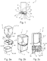
- FIG. 2 illustrates schematic views of a cartridge receptacle 10 and a cartridge system 1 according to a second embodiment of the present invention.
- the second embodiment differs from the first embodiment in that the cartridge receptacle 10 is no longer made in two parts (separate cover element 60 and outlet element 61) but in one piece, ie cover element 60 and outlet element 61 are formed as a common part (the cartridge receptacle 10) the cartridge 2 is clipped in the manner described above and mixing chamber 8, beverage outlet 11, cartridge unloading device 34 and fluid supply 12 has. So that the cartridge 2 is closed aroma-tight during the storage and transport of the cartridge system 1, the cartridge opening 63 is closed with a sealing element 18 in the form of a thin sealing film in the present embodiment. After the production of the cartridge 2 in the blow-molding process, the sealing film is glued or sealed onto the edge of the cartridge opening 63 (see FIG. 3a ). Only then is the cartridge receptacle 10 clipped onto the cartridge 2 (see FIG. 3b ).
- FIGS. 3a and 3b an alternative is shown in which the cartridge 2 is made not in the blow molding process but in the injection molding process.
- the cartridge 2 has here a further cartridge opening, which is closed by a further sealing film 19 by the further sealing film 19 is sealed analogously to the edge of the other cartridge opening.
- this alternative is less preferred.
- the Figures 3d to 3g are therefore based on the in FIGS. 3a and 3b shown cartridge 2.
- the cartridge receptacle 10 now has, in the second embodiment, a fixed piercing spike 73 which projects in the direction of the cartridge 2.
- the piercing mandrel 73 pierces the sealing element 18.
- the cartridge 2 is initially seated in a preposition within the cartridge receptacle 10, in which the piercing mandrel 73 of the sealing element 18th is spaced. Only immediately before, During or immediately after the insertion of the cartridge system 1 into the beverage preparation machine 3 or immediately after the initiation of the beverage production process, the cartridge 2 is transferred from this position to an end position in which the piercing mandrel 73 pierces the sealing element 18.
- the embarkstechdorn 73 projects through the sealing element 18 in the cartridge opening 63 in the direction of the reservoir 6.
- On the outside of the Aufstechdorns 73 a plurality of side channels 71 are introduced, which are in the form of mutually parallel grooves open on one side. After piercing the sealing element 18, the side channels 71 enter into fluid communication with the reservoir 6, so that the beverage substance 7 can flow around the edges of the pierced sealing element 18 in the direction of the mixing chamber 8.
- the cross-section of the side channels 71 and / or the number of side channels 71 is preferably adapted to the viscosity of the beverage substance 7, so that the side channels 71 control the flow of the beverage substance 7 in the direction of the mixing chamber 8 or limit.
- a high viscosity a plurality of side channels 71 and / or side channels 71 with a larger cross section are used, while at a lower viscosity fewer side channels 71 and / or side channels 71 with a smaller cross section are provided.
- the Aufstechdorn 73 has a through hole in which a compressed air tip 72 is arranged movable.
- the compressed air tip 72 can not reach between a retracted position in which the compressed air tip 72 in the direction of the reservoir 6 does not protrude beyond the piercing spike 73 (shown in FIG. 3f ), and an extended position in which the compressed air tip 72 projects beyond the spike 73 into the cartridge opening 62 or into the reservoir 6 (shown in FIG. 3g ), be moved.
- the compressed air line 40 is integrated, which is connected to the compressed air connection 42.
- At a side facing away from the reservoir 6 of the compressed air tip 72 of the compressed air port 42 is formed so that it is accessible from outside the cartridge receptacle 10 and can be connected directly to the compressed air source 41 of the beverage preparation machine 3.
- the compressed air tip 72 is transferred from the retracted position toward the extended position after the sealing member 18 has been perforated by the piercing mandrel 73.
- Compressed air is then blown into the reservoir 6 with the aid of the compressed air tip 72, so that the beverage substance 7 is forced through the side channels 71 into the mixing chamber 8.
- the beverage substance 7 mixes with the fluid and thus forms the beverage 70.
- the compressed air tip 72 during or after insertion of the cartridge system 1 in the beverage preparation machine 3 or after the start of the beverage production process from the retracted position in the extended position is transferred. This is done in particular by compressed air is applied to the compressed air tip 72 and so the compressed air tip 72 is moved from the retracted position to the extended position.
- both the fluid source 91 and the compressed air source 41 are coupled directly to the fluid supply 12 and the compressed air connection 42 as soon as the cartridge system 1 is inserted into the beverage preparation machine 3 or a beverage production process is started and in particular before the sealing element 18 is punctured.
- a recontamination in the direction of the beverage preparation machine 3 is effectively avoided because the fluid supply 12 and the cartridge unloader 34 immediately upon insertion of the cartridge system 1 is under pressure and thus prevents beverage substance 7 in the direction of the fluid source 91 and Druckbuchmaschine 41 wanders.
- the beverage substance 7 can thus proceed, starting from the reservoir 6, only in the direction of the mixing chamber 8 as soon as the sealing element 18 is opened.
- FIG. 2 illustrates schematic views of a cartridge receptacle 10 and a cartridge system 1 according to a third embodiment of the present invention.
- the third embodiment is similar to that of FIGS. 3a to 3g illustrated second embodiment, wherein in the third embodiment, in contrast to the second embodiment, the piercing mandrel 73 is not fixedly connected to the cartridge receptacle 10, but the cartridge receptacle 10 instead has a mandrel guide 80 in which the Aufstechdorn 73 is slidably mounted.
- the sealing element 18 is not opened here by a relative movement between the cartridge 2 and cartridge receptacle 10, but by a transfer of the displaceable piercing mandrel 73 between a retracted position in which the piercing mandrel 73 is spaced from the sealing element 18 (see FIG. FIG. 4b ), and an extended position in which the piercing mandrel 73 pierces the sealing element 18 (cf. Figure 4c ) and into the cartridge opening 63 and in the reservoir 6 projects.
- the outer wall of the piercing mandrel 73 is in turn provided with the plurality of side channels 82 for guiding the beverage substance 7 in the direction of the mixing chamber 8 when the sealing element 18 is pierced, as already described in the second embodiment.
- the compressed air line 40 is also integrated.
- the piercing mandrel 73 also has no movable compressed air tip 72, as in the second embodiment, but the compressed air line 40 opens through a fixed compressed air tip 72 at the end of Aufstechdorns 73 in the cartridge opening 63.
- no displacement of the compressed air tip 72 relative to the piercing mandrel 73 is necessary. Rather, the compressed air tip 72 protrudes automatically into the through hole 63 when the piercing mandrel 73 has been moved to the extended position.
- the compressed air connection 42 is formed on a side facing away from the reservoir 6 in particular of the piercing mandrel 73, which is thus accessible from outside the cartridge receptacle 10 and can be connected to the compressed air source 41 of the beverage preparation machine 3.
- the piercing mandrel 73 is transferred during or after insertion of the cartridge system 10 in the beverage preparation machine 3 or after starting the beverage production process from the retracted position to the extended position, preferably by compressed air, when connecting the compressed air source 41 to the compressed air port 42, the lower end of the piercing mandrel 73 is formed, flows into the cartridge unloader 34.
- both the fluid source 91 and the compressed air source 41 to be coupled directly to the fluid supply 12 or the compressed air connection 42 as soon as the cartridge system 1 is inserted into the beverage preparation machine 3 or a beverage production process is started and in particular before the sealing element 18 is pierced.
- a recontamination in the direction of the beverage preparation machine 3 is effectively avoided because the fluid supply 12 and the cartridge unloader 34 immediately upon insertion of the cartridge system 1 is under pressure and thus prevents beverage substance 7 in the direction of the fluid source 91 and Druckluftetti 41 wanders.
- the beverage substance 7 can thus proceed, starting from the reservoir 6, only in the direction of the mixing chamber 8 as soon as the sealing element 18 is opened.
- FIGS. 5a is a schematic view of a cartridge receptacle 10 and a cartridge system 1 according to the first, second or third embodiment of the present invention shown in a holding unit 90 of a beverage preparation machine 3 shown.
- a detail view of the holding unit 90 is shown, which is substantially consists of a receptacle for the cartridge receptacle 10, as well as to the fluid source 91 of the beverage preparation machine 3 running line for connection to the fluid supply of the cartridge system 1 comprises.
- Embodiment 1 relates to a cartridge receptacle 10 for producing a beverage 70 by means of a cartridge 2, which comprises a reservoir 6 filled with a beverage substance 7, the cartridge receptacle 10 being insertable into a beverage preparation machine 3 and being connectable to a cartridge 2, the cartridge receptacle 10 being a having the reservoir 6 in fluid communication with the mixing chamber 8 and a fluid opening 12 opening into the mixing chamber 8.
- Embodiment 2 relates to a cartridge receptacle 10 according to embodiment 1, wherein the cartridge receptacle 10 has a cartridge unloading device 34 which is provided for at least partially transferring the beverage substance 7 from the reservoir 6 into the mixing chamber 8.
- Embodiment 3 relates to a cartridge receptacle 10 according to one of the preceding embodiments, wherein the cartridge receptacle 10 is firmly or detachably connectable to the cartridge 2 and / or wherein the mixing chamber 8 in the region of the mouth of the fluid supply 12 in the mixing chamber 8 has mixed structures.
- Embodiment 4 relates to a cartridge receptacle 10 according to one of the preceding embodiments, wherein the cartridge unloader 34 comprises a compressed air connection 42 for connection to the compressed air source 41 and a compressed air line 40 which extends from the compressed air connection 42 to a compressed air outlet 43, and wherein the compressed air outlet 43 in particular in the direction of the reservoir 6 of the cartridge 2 protrudes to inject compressed air into the reservoir 6.
- the cartridge unloader 34 comprises a compressed air connection 42 for connection to the compressed air source 41 and a compressed air line 40 which extends from the compressed air connection 42 to a compressed air outlet 43, and wherein the compressed air outlet 43 in particular in the direction of the reservoir 6 of the cartridge 2 protrudes to inject compressed air into the reservoir 6.
- Embodiment 5 relates to a cartridge receptacle 10 according to embodiment 4, wherein the cartridge unloading device 34 is designed such that the beverage substance 7 is pressed from the reservoir 6 into the mixing chamber 8 by the compressed air.
- Embodiment 6 relates to a cartridge receptacle 10 according to one of the preceding embodiments, wherein the mixing chamber 8 has a beverage outlet 11, through which the beverage 70 formed by mixing the beverage substance 7 with the fluid is dispensed, wherein the cartridge receptacle 10 is preferably designed such that the Beverage 70 from the beverage outlet 11 directly into a portable vessel can be introduced.
- Embodiment 7 relates to a cartridge receptacle 10 according to one of the preceding embodiments, wherein the cartridge receptacle 10 with the cartridge 2 via a latching connection 50 is releasably connectable.
- Embodiment 8 relates to a cartridge receptacle 10 according to embodiment 7, wherein the cartridge receptacle 10 has elastic latching elements 51 which engage behind a retaining flange 52 formed on the cartridge 2 when the cartridge 2 is secured in the cartridge receptacle 10.
- Embodiment 9 relates to a cartridge receptacle 10 according to one of the preceding embodiments, wherein the cartridge receptacle 10 is substantially integrally formed, or wherein the cartridge receptacle 10 comprises a cover element 60 and a discharge element 61 connected to the cover element 60.
- Embodiment 10 relates to a cartridge receptacle 10 according to embodiment 9, wherein the cover element 60 with the cartridge 2 reversibly connectable and in particular latched, that a reservoir 6 leading to the cartridge opening 63 is at least temporarily or partially closed by the cover member 60, and wherein the outlet member 61st reversibly connectable to the cover member 60 and in particular can be latched.
- Embodiment 11 relates to a cartridge receptacle 10 according to embodiment 10, wherein the outlet element 61, the fluid supply 12, the compressed air port 42, the mixing chamber 8 and / or the beverage outlet 11 has.
- Embodiment 12 relates to a cartridge receptacle 10 according to embodiment 9 or 11, wherein the cover element 60 has the projecting in the direction of the reservoir 6 compressed air outlet 43, in particular in the form of a hollow mandrel, which via the compressed air line 40th is in operative connection with the compressed air connection 42 formed on the cover element 60 or on the outlet element 61.
- Embodiment 13 relates to a cartridge receptacle 10 according to one of embodiments 10 to 12, wherein by means of a valve unit, a fluid connection between the cartridge opening 63 and the mixing chamber 8 can be produced, wherein the valve unit by a relative movement between the cover member 60 and the outlet member 61 from a closed state in an open state for the preparation of the fluid connection can be transferred.
- Embodiment 14 relates to a cartridge receptacle 10 according to one of embodiments 10 to 13, wherein the cover member 60 has a through opening 62 leading to the cartridge opening 63, wherein the valve unit is formed by the through-hole 62 and a projection 64 of the outlet member 61 projecting into the through-hole 62 is displaced by a relative movement between the cover member 60 and the outlet member 61 of the projection 64 from a passage opening 62 occluding position into a passage opening 62 partially releasing position.
- Embodiment 15 relates to a cartridge receptacle 10 according to embodiment 14, wherein the wall of the passage opening 62 is provided with at least one side channel 65 and wherein the projection 64 in the passage opening 62 partially releasing position in the region of the at least one side channel 65 is arranged.
- Embodiment 16 relates to a cartridge receptacle 10 according to one of embodiments 1 to 9, wherein the cartridge 2 has a cartridge opening 63 in fluid communication with the reservoir 6, the cartridge opening 63 being closed by a sealing element 18, the sealing element 18 in particular comprising a sealing film, which is consumed on the edge of the cartridge opening 63 and preferably sealed.
- Embodiment 17 relates to a cartridge receptacle 10 according to embodiment 16, wherein the cartridge receptacle 10 comprises a piercing mandrel 73 projecting in the direction of the cartridge 2 such that the piercing mandrel 73 pierces the sealing element 18 by means of a relative movement between the cartridge receptacle 10 and the cartridge 2 and establishes a fluid connection between the reservoir 6 and the mixing chamber 8 is generated.
- Embodiment 18 relates to a cartridge receptacle 10 according to embodiment 17, wherein in the wall of the piercing spike 73 at least one side channel 71 for conducting the beverage substance 7 in the direction of the mixing chamber 8, when the sealing element 18 is pierced, is introduced.
- Embodiment 19 relates to a cartridge receptacle 10 according to one of embodiments 16 to 18, wherein the piercing mandrel 73 has a through hole in which a compressed air tip 72 between a retracted position in which the compressed air tip 72 does not protrude in the direction of the reservoir 6 over the embarkstechdorn 73, and an extended position in which the compressed air tip 72 protrudes over the Aufstechdorn 73 into the reservoir 6, is slidably mounted.
- Embodiment 20 relates to a cartridge receptacle 10 according to embodiment 19, wherein in the compressed air tip 72, the compressed air line 40 is integrated and wherein on a reservoir 6 in particular the opposite side of the compressed air tip 72 of the compressed air port 42 is formed, the compressed air port 42 preferably accessible from outside the cartridge receptacle 10 is.
- Embodiment 21 relates to a cartridge receptacle 10 according to one of the embodiments 19 or 20, wherein the compressed air tip 72 is transferred from the retracted position to the extended position upon insertion of the cartridge system 1 into the beverage preparation machine by a trigger element of the beverage preparation machine.
- Embodiment 22 relates to a cartridge receptacle 10 according to embodiment 16, wherein the cartridge receptacle 10 comprises a mandrel guide 80 and a piercing mandrel 81 displaceably mounted within the mandrel guide 80, wherein the piercing mandrel 81 is spaced between a retracted position in which the piercing mandrel 81 is spaced from the sealing element 19, and an extended position in which the piercing mandrel 81 pierces the sealing element 18 and extends into the reservoir 6, is displaceable.
- Embodiment 23 relates to a cartridge receptacle 10 according to embodiment 22, wherein in the outer wall of the Aufstechdorns 81 at least one side channel 82 for guiding the beverage substance 7 in the direction of the mixing chamber 8 when the sealing element 18 is pierced introduced.
- Embodiment 24 relates to a cartridge receptacle 10 according to one of embodiments 22 or 23, wherein in the Aufstechdorn 81, the compressed air line 40 is integrated and wherein at one of the reservoir 6 in particular facing away from the Aufstechdorns 81 of the compressed air connection 42 is formed, wherein the compressed air connection 42 is preferably accessible from outside the cartridge receptacle 10.
- Embodiment 25 relates to a cartridge receptacle 10 according to one of embodiments 22 to 24, wherein the piercing mandrel 81 is transferred from the retracted position to the deployed position upon insertion of the cartridge system 1 into the beverage preparation machine by a trigger element of the beverage preparation machine.
- Embodiment 26 relates to a cartridge system 1 for producing a beverage 70, wherein the cartridge system 1 can be inserted into a beverage preparation machine 3, the cartridge system 1 comprising a cartridge 2, which comprises a reservoir 6 filled with a beverage substance 7, and a cartridge receptacle connected to the cartridge 2 10 according to one of the preceding embodiments.
- Embodiment 27 relates to a cartridge system according to embodiment 26, wherein the cartridge receptacle 10 a mixing chamber 8, a cartridge unloading device 34, which is provided for at least partially transferring the beverage substance 7 from the reservoir 6 into the mixing chamber 8, and a fluid supply 12, which opens into the mixing chamber 8 , having.
- Embodiment 28 relates to a cartridge system according to embodiment 27, wherein the cartridge 2 is fixedly or detachably connected to the cartridge receptacle 10, wherein the cartridge system 1 is designed such that the beverage substance 7 is pressed from the reservoir 6 into the mixing chamber 8 by the compressed air.
- Embodiment 29 relates to a cartridge system according to one of embodiments 27 or 28, wherein the fluid supply 12 is supplied with fluid which is cooled by a refrigeration unit, the refrigeration unit being part of the beverage preparation machine or a separate refrigerator operatively connected to the beverage preparation machine.
- Embodiment 30 relates to a cartridge system according to embodiment 29, wherein the cooling unit comprises a compressor cooling unit, an absorber cooling unit or a thermoelectric cooler.
- the cooling unit comprises a compressor cooling unit, an absorber cooling unit or a thermoelectric cooler.
- Embodiment 31 relates to a cartridge system according to any one of Embodiments 27 to 30, wherein the fluid supply 12 is supplied with fluid which is carbonated by a carbonator.
- Embodiment 32 relates to a cartridge system according to embodiment 31, wherein the carbonator is part of the beverage preparation machine 3 and wherein the carbonator has a receptacle for a CO 2 cartridge and a supply means for displacing the fluid with CO 2 from the CO 2 cartridge.
- Embodiment 33 relates to a cartridge system according to one of embodiments 27 to 32, wherein the cartridge receptacle 10 is releasably connected to the cartridge 2 via a latching connection 50.
- Embodiment 34 relates to a cartridge system according to embodiment 33, wherein the cartridge receptacle 10 has elastic latching elements 51, which engage behind a holding flange 52 formed on the cartridge 2 when the cartridge 2 is mounted in the cartridge receptacle 10.
- Embodiment 35 relates to a cartridge system according to one of embodiments 26 to 34, wherein the cartridge 2 has a cartridge opening 63 in fluid communication with the reservoir 6, the cartridge opening 63 being closed by a sealing element 18, the sealing element 18 in particular comprising a sealing foil which is used up on the edge of the cartridge opening 63 and preferably sealed.
- Embodiment 36 relates to a cartridge system according to one of embodiments 26 to 35, wherein the cartridge 2 has on a side opposite the cartridge opening 63 a further cartridge opening, which is closed by a further sealing element 10, in particular a further sealing film.
- Embodiment 37 relates to a beverage preparation machine 3 for producing a beverage 70 into which a cartridge system 1 according to one of embodiments 26 to 36 can be inserted, wherein the beverage preparation machine 3 has a holding unit 90 into which the cartridge receptacle 10 connected to the cartridge 2 can be inserted Fluid source 91 for feeding the fluid into the fluid supply 12 and a compressed air source 41 for injecting compressed air into the compressed air connection 42nd
- Embodiment 38 relates to a beverage preparation machine 3 according to Embodiment 37, wherein the beverage preparation machine 3 has the triggering member for transferring the compressed air tip 72 or the piercing spike 81 from the retracted position to the extended position.
- Embodiment 40 relates to a method according to embodiment 39, wherein the beverage substance 7 is transferred by compressed air from the reservoir 6 into the mixing chamber 8.
- Embodiment 41 relates to a method according to one of the embodiments 39 or 40, wherein the fluid is cooled and / or carbonized before being fed into the mixing chamber 8.
- Embodiment 42 relates to a method according to one of embodiments 39 to 41, wherein before, during or after insertion of the cartridge system 1 in the holding unit 90, a compressed air tip 72 or the piercing mandrel 81 is transferred from a retracted position to an extended position and a sealing element 18 at the cartridge opening 63 perforated.
- Embodiment 43 relates to a method according to one of the embodiments 39 to 42, wherein before, during or after insertion of the cartridge system 1 in the holding unit 90, a fluid connection between the reservoir 6 and the mixing chamber 8 by opening a valve unit caused by a relative movement between a cover member 60th and a discharge element 61 is brought about.
Abstract
Es wird eine Kartuschenaufnahme zur Herstellung eines Getränks mittels einer Kartusche vorgeschlagen, wobei die Kartzuschenaufnahme ein mit einer Getränkesubstanz gefülltes Reservoir umfasst, wobei die Kartuschenaufnahme in eine Getränkezubereitungsmaschine einsetzbar ist und mit einer Kartusche verbindbar ist, wobei die Kartuschenaufnahme eine mit dem Reservoir in Fluidverbindung bringbare Mischkammer und eine in die Mischkammer mündende Fluidzuführung aufweist, die Kartusche eine mit dem Reservoir in Fluidverbindung stehende Kartuschenöffnung aufweist, wobei die Kartuschenöffnung mit einem Dichtelement verschlossen ist, wobei das Dichtelement eine Dichtfolie umfasst, die auf den Rand der Kartuschenöffnung aufgebracht ist, wobei die Kartuschenaufnahme einen in Richtung der Kartusche vorstehenden Aufstechdorn derart umfasst, dass durch eine Relativbewegung zwischen Kartuschenaufnahme und Kartusche der Aufstechdorn das Dichtelement durchsticht und eine Fluidverbindung zwischen dem Reservoir und der Mischkammer erzeugt wird.The invention relates to a cartridge receptacle for producing a beverage by means of a cartridge, wherein the cartridge receptacle comprises a reservoir filled with a beverage substance, the cartridge receptacle being insertable into a beverage preparation machine and connectable to a cartridge, the cartridge receptacle having a mixing chamber fluidably connected to the reservoir and a fluid inlet opening into the mixing chamber, the cartridge having a cartridge opening in fluid communication with the reservoir, the cartridge opening being closed with a sealing element, the sealing element comprising a sealing foil applied to the edge of the cartridge opening, the cartridge receptacle having a in the direction of the cartridge protruding spike comprises such that by a relative movement between the cartridge receptacle and cartridge piercing the pierces the sealing element and a fluid connection between the reservoir and the mixing chamber is generated.
Description
Die vorliegende Erfindung geht aus von einem in eine Getränkezubereitungsmaschine einsetzbares Kartuschensystem zur Herstellung eines Getränks, insbesondere eines Kaltgetränks, aufweisend eine Kartusche, die ein mit einer Getränkesubstanz gefülltes Reservoir aufweist, und eine mit der Kartusche reversibel verbindbare Kartuschenaufnahme, in welche die Kartusche reversibel einsetzbar ist, und mit einer Kartuschenentladeeinrichtung, welche ein zumindest teilweises Überführen der Getränkesubstanz vom Reservoir in eine Mischkammer bewirkt.The present invention is based on a cartridge system which can be used in a beverage preparation machine for producing a beverage, in particular a cold drink, comprising a cartridge having a reservoir filled with a beverage substance, and a cartridge receptacle reversibly connectable to the cartridge, into which the cartridge can be reversibly inserted , and a cartridge unloading device which effects at least partial transfer of the beverage substance from the reservoir into a mixing chamber.
Solche Systeme sind aus dem Stand der Technik, beispielsweise aus
Eine große Herausforderung bei solchen Systemen ist, während der Herstellung des Getränks eine Rückkontamination der Getränkezubereitungsmaschine sicher und vollständig zu unterbinden, da andernfalls die Gefahr einer Verunreinigung bis hin zur Schimmelpilzbildung innerhalb der Getränkezubereitungsmaschine besteht. Dies gilt insbesondere für Kartuschen die fruchtzuckerhaltige, alkoholhaltige oder milchhaltige Getränkesubstanzen enthalten.A major challenge with such systems is to safely and completely prevent recontamination of the beverage making machine during manufacture of the beverage, otherwise there is a risk of contamination through mold formation within the beverage making machine. This applies in particular to cartridges containing fructose, alcoholic or milk-containing beverage substances.
Bei aus dem Stand der Technik bekannten Systemen wird üblicherweise die Kartusche in eine als fester Bestandteil der Getränkezubereitungsmaschine ausgebildete Kartuschenaufnahme eingesetzt und sodann die Kartusche auf beiden Seiten, d.h. auf einer Einlassseite und auf einer Auslassseite geöffnet. Auf der Einlassseite wird anschließend mittels einer Fluidzuführung Wasser in die Kartusche eingeleitet, so dass sich das Getränk durch Vermischen der Getränkesubstanz mit dem Wasser schon innerhalb des Reservoirs in der Kartusche bildet. Auf der Auslassseite verlässt das Getränk die Kartusche und wird zu einem Trinkgefäß geleitet. Das Wasser durchströmt das Reservoir hierbei vollständig und bewirkt somit ein Ausleiten der Getränkesubstanz aus dem Reservoir.In systems known from the prior art, the cartridge is usually introduced into a cartridge receptacle formed as an integral part of the beverage preparation machine and then open the cartridge on both sides, ie on an inlet side and on an outlet side. On the inlet side, water is subsequently introduced into the cartridge by means of a fluid feed, so that the beverage already forms within the reservoir in the cartridge by mixing the beverage substance with the water. On the outlet side, the beverage leaves the cartridge and is directed to a drinking vessel. The water flows through the reservoir here completely and thus causes a discharge of the beverage substance from the reservoir.
Es hat sich gezeigt, dass beim Einleiten des Wassers direkt in das mit der Getränkesubstanz gefüllte Reservoir eine Rückkontamination der Zuführung nicht vollständig verhindert werden kann, weil das Reservoir üblicherweise vollständig mit der Getränkesubstanz gefüllt ist und dadurch beim Einleiten des Wassers ein erheblicher Druckanstieg im Reservoir stattfindet. Sowohl dieser Druckanstieg im Reservoir als auch das Durchspülen des Reservoirs sorgt dafür, dass während und/oder kurz nach der Getränkeherstellung kleinste Tropfen, Partikel und/oder Schwebestoffe der Getränkesubstanz in die Fluidzuführung gelangen und dort zu einer kontinuierlichen Verunreinigung der Getränkezubereitungsmaschine führen.It has been found that when the water is introduced directly into the reservoir filled with the beverage substance, recontamination of the feed can not be completely prevented, because the reservoir is usually completely filled with the beverage substance and, as a result, a considerable increase in pressure takes place in the reservoir when the water is introduced , Both this increase in pressure in the reservoir and the flushing of the reservoir ensures that during and / or shortly after the beverage production smallest drops, particles and / or suspended matter of the beverage substance in the fluid supply and there lead to a continuous contamination of the beverage preparation machine.
Es ist daher eine Aufgabe der vorliegenden Erfindung eine Kartuschenaufnahme, ein Kartuschensystem, eine Getränkezubereitungsmaschine und ein Verfahren zur Herstellung eines Getränks durch Einsetzen des Kartuschensystems in eine Getränkezubereitungsmaschine zur Verfügung zu stellen, bei welchem eine Rückkontamination der Getränkezubereitungsmaschine wirksam vermieden wird.It is therefore an object of the present invention to provide a cartridge receptacle, a cartridge system, a beverage preparation machine and a method for producing a beverage by inserting the cartridge system in a beverage preparation machine, in which a recontamination of the beverage preparation machine is effectively avoided.
Diese Aufgabe wird durch eine Kartuschenaufnahme gemäß Anspruch 1 und ein Kartuschensystem nach Anspruch 13 gelöst.This object is achieved by a cartridge receptacle according to
Die erfindungsgemäße Kartuschenaufnahme und das erfindungsgemäße Kartuschensystem haben gegenüber dem Stand der Technik den Vorteil, dass die Fluidzuführung anders als beim Stand der Technik nicht in das Reservoir der Kartusche, sondern in die vom Reservoir separierte Mischkammer mündet. Hierdurch wird wirksam und in einer einfach und kostengünstig zu realisierenden Weise verhindert, dass durch die Fluidzuführung eine Rückkontamination der Getränkezubereitungsmaschine erfolgt. Hierfür wird das Reservoir nicht von dem Fluid durchspült, sondern gemäß der vorliegenden Erfindung gelangen die Getränkesubstanz und das Fluid getrennt voneinander in die Mischkammer. Das Fluid wird direkt in die Mischkammer geleitet, während die Getränkesubstanz durch die Kartuschenentladeeinrichtung und unabhängig vom Fluid in die Mischkammer überführt wird. Es hat sich gezeigt, dass hierdurch eine Rückkontamination der Getränkezubereitungsmaschine in einer im Vergleich zum Stand der Technik deutlich wirksameren Art und Weise unterbunden wird, insbesondere da im Reservoir kein direkt auf die Fluidzuführung wirkender Überdruck erzeugt wird. Die Ausbildung der Mischkammer in der Kartuschenaufnahme, die in die Getränkezubereitungsmaschine reversibel einsetzbar ist, sorgt vorteilhafterweise dafür, dass die Mischkammer Teil des austauschbaren Kartuschensystem ist. Auf diese Weise wird eine Verunreinigung der Getränkezubereitungsmaschine durch die Getränkesubstanz wirksam vermieden, weil lediglich Teile des austauschbaren Einweg- oder Mehrwegkartuschensystems mit der Getränkesubstanz in Kontakt gelangen. Denkbar ist auch, dass die Kartusche bei jedem Getränkeherstellungsvorgang ausgetauscht wird, während die Kartuschenaufnahme für mehrere Getränkeherstellungsvorgänge verwendet wird, bevor auch sie ausgetauscht wird. Vorzugsweise ist das Reservoir des Kartuschensystems durch ein Dichtelement verschlossen, welches erst beim oder nach dem Einsetzen des Kartuschensystems in die Getränkezubereitungsmaschine geöffnet wird. Das Dichtelement dient dazu, die Kartusche beim Transport oder der Lagerung aromadicht zu verschließen, wodurch beispielsweise eine lange Haltbarkeit der Kartusche zu erzielen ist.The cartridge receptacle according to the invention and the cartridge system according to the invention have the advantage over the prior art that, unlike the prior art, the fluid supply does not discharge into the reservoir of the cartridge but into the mixing chamber separated from the reservoir. As a result, it is effectively and in a simple and inexpensive manner to be realized prevents backfilling of the beverage preparation machine by the fluid supply. For this purpose, the reservoir is not flushed by the fluid, but according to the present invention, the beverage substance and the fluid pass separately into the mixing chamber. The fluid is passed directly into the mixing chamber while the beverage substance passes through the cartridge unloader and is transferred independently of the fluid in the mixing chamber. It has been found that in this way a recontamination of the beverage preparation machine is prevented in a significantly more effective manner compared to the prior art, in particular since no overpressure acting directly on the fluid supply is generated in the reservoir. The formation of the mixing chamber in the cartridge receptacle, which can be used reversibly in the beverage preparation machine, advantageously ensures that the mixing chamber is part of the exchangeable cartridge system. In this way, contamination of the beverage making machine by the beverage substance is effectively avoided because only parts of the disposable or disposable replaceable cartridge system contact the beverage substance. It is also conceivable that the cartridge be replaced in each beverage manufacturing process, while the cartridge receptacle is used for several beverage manufacturing operations, before it is replaced. Preferably, the reservoir of the cartridge system is closed by a sealing element, which is opened only during or after insertion of the cartridge system in the beverage preparation machine. The sealing element serves to close the cartridge during transport or storage aroma-tight, which, for example, a long shelf life of the cartridge can be achieved.
Vorteilhafte Ausgestaltungen und Weiterbildungen der Erfindung sind den Unteransprüchen, sowie der Beschreibung unter Bezugnahme auf die Zeichnungen entnehmbar.Advantageous embodiments and modifications of the invention are the dependent claims, as well as the description with reference to the drawings.
Gemäß einer bevorzugten Ausführungsform der vorliegenden Erfindung ist vorgesehen, dass die Kartusche fest oder lösbar mit der Kartuschenaufnahme verbunden ist bzw. die Kartuschenaufnahme fest oder lösbar mit der Kartusche verbindbar ist. Vorzugsweise ist die Kartuschenaufnahme reversibel an der Kartusche befestigt, besonders bevorzugt durch eine Rastverbindung. Denkbar ist beispielsweise, dass die Kartusche eine Art Flaschenhals (aufweisend die Kartuschenöffnung) mit einem umlaufenden Halteflansch umfasst und die Kartuschenaufnahme auf den Flaschenhals geclipst wird. Dabei hintergreifen insbesondere elastische Rastelemente, wie beispielsweise Halteärmchen den Halteflansch. Die Kartusche ist insbesondere als Einmalbehältnis für die Getränkesubstanz vorgesehen, insbesondere recycelbar. Vorteilhafterweise kann die Kartuschenaufnahme mehrfach verwendet werden, indem sie an verschiedenen Kartuschen befestigbar ist. Zudem wird die Herstellung des Kartuschensystem vereinfacht, da die Kartusche und die Kartuschenaufnahme separat hergestellt werden können und lediglich die Kartuschenaufnahme anschließend auf die Kartusche aufgeclipst wird. Die Kartusche umfasst insbesondere eine eckige, runde oder abgerundete Flasche. Die Kartusche ist insbesondere aus Kunststoff in einem Blas-Spritzformformverfahren oder in einem Spritzformverfahren oder mit weiteren Formverfahren hergestellt. Grundsätzlich wäre aber auch ein Tiefziehverfahren zur Herstellung der Kartusche vorstellbar. Ebenso wäre es natürlich auch denkbar, dass die Kartusche mehrfach verwendbar ist.According to a preferred embodiment of the present invention it is provided that the cartridge is fixed or detachably connected to the cartridge receptacle or the cartridge receptacle is fixed or detachably connectable to the cartridge. Preferably, the cartridge receptacle is reversibly attached to the cartridge, particularly preferably by a latching connection. It is conceivable, for example, that the cartridge comprises a kind of bottleneck (comprising the cartridge opening) with a peripheral holding flange and the cartridge receptacle is clipped onto the bottleneck. In particular, elastic latching elements, such as retaining sleeves, engage behind the retaining flange. The cartridge is provided in particular as a disposable container for the beverage substance, in particular recyclable. Advantageously, the cartridge receptacle can be used several times by being attachable to different cartridges. In addition, the production of the cartridge system is simplified because the cartridge and the cartridge holder can be made separately and only the cartridge holder is then clipped onto the cartridge. The cartridge comprises in particular a square, round or rounded bottle. The cartridge is in particular made of plastic in a blow-molding process or in an injection molding process or by further molding processes. In principle, however, a deep drawing process for producing the cartridge would be conceivable. Likewise, it would of course also conceivable that the cartridge is reusable.
Gemäß einer weiteren bevorzugten Ausführungsform der vorliegenden Erfindung ist vorgesehen, dass die Kartuschenentladeeinrichtung einen Druckluftanschluss zum Anschluss an die Druckluftquelle und eine Druckluftleitung umfasst, welche sich vom Druckluftanschluss zu einem Druckluftauslass erstreckt, und wobei der Druckluftauslass insbesondere in Richtung des Reservoirs der Kartusche vorsteht, um Druckluft in das Reservoir einzublasen. Die in die Kartuschenaufnahme integrierte Kartuschenentladeeinrichtung umfasst im Sinne der vorliegenden Erfindung also zunächst nur eine Druckluftleitung, durch welche Druckluft von außen in das Reservoir eingeleitet werden kann. Das Kartuschensystem derart ausgebildet ist, dass durch die Druckluft die Getränkesubstanz aus dem Reservoir in die Mischkammer gedrückt wird. Die Druckluft wird insbesondere von der Getränkezubereitungsmaschine bereitgestellt. Denkbar ist, dass eine Druckluftquelle direkt an den Druckluftanschluss angekoppelt wird, sobald das Kartuschensystem in die Getränkezubereitungsmaschine eingesetzt wird. Dies hat den Vorteil, dass eine Rückkontamination in Richtung der Getränkezubereitungsmaschine wirksam vermieden wird, weil die Kartuschenentladeeinrichtung sofort beim Einsetzen des Kartuschensystems unter Druck steht und somit verhindert wird, dass Getränkesubstanz in Richtung der Druckluftleitung und insbesondere in Richtung der Druckluftquelle der Getränkezubereitungsmaschine wandert. Die Getränkesubstanz kann sich ausgehend vom Reservoir somit lediglich in Richtung der Mischkammer bewegen.According to a further preferred embodiment of the present invention, it is provided that the cartridge unloading device comprises a compressed air connection for connection to the compressed air source and a compressed air line which extends from the compressed air connection to a compressed air outlet, and wherein the compressed air outlet projects in particular in the direction of the reservoir of the cartridge to compressed air to blow into the reservoir. In the sense of the present invention, the cartridge unloading device integrated in the cartridge receptacle therefore initially comprises only a compressed-air line through which compressed air can be introduced from the outside into the reservoir. The cartridge system is designed such that the beverage substance is forced out of the reservoir into the mixing chamber by the compressed air. The compressed air is provided in particular by the beverage preparation machine. It is conceivable that a compressed air source is coupled directly to the compressed air connection as soon as the cartridge system is inserted into the beverage preparation machine. This has the advantage that recontamination in the direction of the beverage preparation machine is effectively avoided because the cartridge unloader immediately upon insertion of the cartridge system is under pressure and thus prevents beverage substance migrates in the direction of the compressed air line and in particular in the direction of the compressed air source of the beverage preparation machine. The beverage substance can thus only move in the direction of the mixing chamber starting from the reservoir.
Gemäß einer weiteren bevorzugten Ausführungsform der vorliegenden Erfindung ist vorgesehen, dass die Mischkammer einen Getränkeauslauf aufweist, durch welchen das aus einer Vermischung der Getränkesubstanz mit dem Fluid gebildete Getränk abgegeben wird, wobei das Kartuschensystem vorzugsweise derart ausgebildet ist, dass das Getränk aus dem Getränkeauslauf direkt in ein portables Gefäß einleitbar ist. In vorteilhafter Weise gerät somit weder die Getränkesubstanz noch das erzeugte Getränk in Kontakt mit einem Teil der Getränkezubereitungsmaschine, so dass nahezu jegliche (Rück-)Kontamination der Getränkezubereitungsmaschine verhindert wird. Das Fluid wird der Mischkammer separat zugeführt. Vorzugsweise wird das Fluid unter Druck in die Mischkammer eingeleitet. Das Fluid wird insbesondere von der Getränkezubereitungsmaschine bereitgestellt. Denkbar ist, dass eine Fluidquelle direkt an einen entsprechenden Fluidanschluss der Kartuschenaufnahme angekoppelt wird, sobald das Kartuschensystem in die Getränkezubereitungsmaschine eingesetzt wird. Der Fluidanschluss steht dabei über eine Fluidleitung in Fluidverbindung mit der Mischkammer. Dies hat den Vorteil, dass eine Rückkontamination in Richtung der Getränkezubereitungsmaschine wirksam vermieden wird, weil der Fluidanschluss sofort beim Einsetzen des Kartuschensystems unter Druck steht und somit verhindert wird, dass Getränkesubstanz in Richtung der Fluidleitung und insbesondere in Richtung der Fluidquelle der Getränkezubereitungsmaschine wandert. Die Getränkesubstanz und das Getränk kann sich ausgehend von der Mischkammer somit lediglich in Richtung des Getränkeauslasses bewegen. Das Fluid umfasst insbesondere Wasser, vorzugsweise unter Druck stehendes, gekühltes und/oder karbonisiertes Trinkwasser.According to a further preferred embodiment of the present invention, it is provided that the mixing chamber has a beverage outlet through which the beverage formed from a mixture of the beverage substance with the fluid is dispensed, wherein the cartridge system is preferably designed such that the beverage from the beverage outlet directly into a portable vessel can be introduced. In an advantageous manner, neither the beverage substance nor the beverage produced thus comes into contact with a part of the beverage preparation machine, so that almost any (re) contamination of the beverage preparation machine is prevented. The fluid is supplied separately to the mixing chamber. Preferably, the fluid is introduced under pressure into the mixing chamber. The fluid is provided in particular by the beverage preparation machine. It is conceivable that a fluid source is coupled directly to a corresponding fluid port of the cartridge receptacle as soon as the cartridge system is inserted into the beverage preparation machine. The fluid connection is in fluid communication with the mixing chamber via a fluid line. This has the advantage that a return contamination in the direction of the beverage preparation machine is effectively avoided because the fluid port immediately upon insertion of the cartridge system is under pressure and thus prevents beverage substance migrates in the direction of the fluid line and in particular in the direction of the fluid source of the beverage preparation machine. The beverage substance and the beverage can thus only move in the direction of the beverage outlet, starting from the mixing chamber. The fluid comprises in particular water, preferably pressurized, cooled and / or carbonated drinking water.
Gemäß einer bevorzugten Ausführungsform der vorliegenden Erfindung ist vorgesehen, dass die Mischkammer mit Mischstrukturen versehen ist. Die Mischstrukturen sorgen in vorteilhafter Weise für eine verbesserte Durchmischung von Getränkesubstanz und Fluid. Hierfür sind die Mischstrukturen insbesondere derart ausgebildet, dass das in die Mischkammer einströmende Fluid verwirbelt wird. Denkbar ist, dass die Mischstrukturen einen oder mehrere Mischstege umfasst, welche im Bereich der Fluidzuführung am Boden der Mischkammer angeordnet sind und sich im Wesentlichen senkrecht zum Einströmrichtung des Fluids erstrecken. Die Mischstege fungieren somit als Barrieren für das Fluid, wodurch das Fluid aufgewirbelt wird und eine bessere Durchmischung mit der Getränkesubstanz erzielt wird.According to a preferred embodiment of the present invention it is provided that the mixing chamber is provided with mixing structures. The mixing structures provide advantageously for improved mixing of beverage substance and fluid. For this purpose, the mixing structures are in particular designed such that the fluid flowing into the mixing chamber is fluidized. It is conceivable that the mixing structures comprise one or more mixing webs, which are arranged in the region of the fluid feed at the bottom of the mixing chamber and extend substantially perpendicular to the inflow direction of the fluid. The mixing webs thus act as barriers for the fluid, causing the fluid to be fluidized and achieving better mixing with the beverage substance.
Gemäß einer weiteren bevorzugten Ausführungsform der vorliegenden Erfindung ist vorgesehen, dass die Fluidzuführung mit Fluid gespeist wird, welches durch ein Kühlaggregat gekühlt wird, wobei das Kühlaggregat Teil der Getränkezubereitungsmaschine oder eines mit der Getränkezubereitungsmaschine in Wirkverbindung stehenden separaten Kühlschranks ist. In vorteilhafter Weise sind somit Kaltgetränke herstellbar, auch wenn die Kartusche nicht gekühlt ist und beispielweise Zimmertemperatur aufweist. Die Integration des Systems in einen bestehenden Kühlschrank hat den Vorteil, dass das bestehende Kühlaggregat des Kühlschranks für die Getränkezubereitungsmaschine in effizienter Weise einfach mitgenutzt werden kann. Insbesondere bei sogenannten "Side-by-side"-Kühlschränken (oft auch als amerikanische Kühlschränke bezeichnet) findet sich in der Front ausreichend Bauraum zur Integration des Systems. Denkbar ist, dass es sich bei der Getränkezubereitungsmaschine um ein Nachrüstset für einen solchen Kühlschrank handelt. Das Kühlaggregat umfasst vorzugsweise eine Kompressorkühleinheit, eine Absorberkühleinheit oder einen thermoelektrischen Kühler.According to a further preferred embodiment of the present invention, it is provided that the fluid supply is supplied with fluid, which is cooled by a cooling unit, wherein the cooling unit is part of the beverage preparation machine or a separate refrigerator in operative connection with the beverage preparation machine. Advantageously, thus cold drinks are produced, even if the cartridge is not cooled and, for example, has room temperature. The integration of the system into an existing refrigerator has the advantage that the existing refrigeration unit of the refrigerator for the beverage preparation machine can be easily shared in an efficient manner. In particular, in so-called "side-by-side" refrigerators (often referred to as American refrigerators) found in the front of sufficient space for integration of the system. It is conceivable that the beverage preparation machine is a retrofit set for such a refrigerator. The refrigeration unit preferably comprises a compressor cooling unit, an absorber cooling unit or a thermoelectric cooler.
Gemäß einer weiteren bevorzugten Ausführungsform der vorliegenden Erfindung ist vorgesehen, dass die Fluidzuführung mit Fluid gespeist wird, welches durch einen Karbonisierer mit Kohlensäure versetzt wird. Denkbar ist, dass der Karbonisierer Teil der Getränkezubereitungsmaschine ist und wobei der Karbonisierer eine Aufnahme für eine CO2-Patrone und eine Zuführeinrichtung zum Versetzen des Fluides mit CO2 aus der CO2-Patrone aufweist. Vorteilhafterweise lassen sich mit dem System somit auch mit Kohlensäure versetzte Erfrischungsgetränke herstellen. Alternativ wäre auch denkbar, dass der Karbonisierer einen externen CO2-Anschluss aufweist.According to a further preferred embodiment of the present invention it is provided that the fluid supply is fed with fluid which is carbonated by a carbonator. It is conceivable that the carbonator is part of the beverage preparation machine and wherein the carbonator a receptacle for a CO 2 cartridge and a supply means for displacing the fluid with CO 2 from the CO 2 cartridge. Advantageously, it is thus also possible to produce carbonated soft drinks with the system. Alternatively, it would also be conceivable that the carbonator has an external CO 2 connection.
Gemäß einer weiteren bevorzugten Ausführungsform der vorliegenden Erfindung ist vorgesehen, dass die Kartuschenaufnahme im Wesentlichen einteilig ausgebildet ist oder wobei die Kartuschenaufnahme ein Deckelelement und ein mit dem Deckelelement verbundenes Auslaufelement umfasst. Im Sinne der vorliegenden Erfindung bedeutet eine einteilige Ausführung der Kartuschenaufnahme insbesondere nicht, dass die Kartuschenaufnahme zwingend nur aus einem einzigen Teil bestehen soll, sondern lediglich, dass die Kartuschenaufnahme in dieser speziellen einteiligen Ausführungsform nicht aus dem Deckelelement und separaten Auslaufelement besteht. Mit anderen Worten: Deckelement und Auslaufelement sind in der einteiligen Ausführungsform einteilig ausgebildet.According to a further preferred embodiment of the present invention, it is provided that the cartridge receptacle is formed essentially in one piece or wherein the cartridge receptacle comprises a cover element and a discharge element connected to the cover element. For the purposes of the present invention, a one-piece embodiment of the cartridge receptacle does not mean, in particular, that the cartridge receptacle should consist of only a single part, but only that the cartridge receptacle in this particular one-part embodiment does not consist of the cover element and separate outlet element. In other words: cover element and outlet element are integrally formed in the one-piece embodiment.
Gemäß einer weiteren bevorzugten Ausführungsform der vorliegenden Erfindung ist vorgesehen, dass das Deckelelement mit der Kartusche derart reversibel verbindbar und insbesondere verrastbar ist, dass eine zum Reservoir führende Kartuschenöffnung durch das Deckelement zumindest temporär oder teilweise verschlossen ist, und wobei das Auslaufelement mit dem Deckelelement reversibel verbindbar und insbesondere verrastbar ist. Zur Herstellung dieser Ausführungsform des Kartuschensystems wird die Kartusche hergestellt, anschließend die Kartusche durch die Kartuschenöffnung mit der Getränkesubstanz gefüllt und anschließend zum Verschließen der Kartuschenöffnung die Kartuschenaufnahme auf die Kartusche geclipst. Das Auslaufelement weist in diesem Fall insbesondere die Fluidzuführung, den Druckluftanschluss, die Mischkammer und den Getränkeauslauf auf, während das Deckelelement den in das Reservoir insbesondere vorstehende Druckluftauslass zum Einleiten der Druckluft in das Reservoir aufweist. Denkbar ist, dass der Druckluftauslass einen hohlen Dorn umfasst, welcher über die Druckluftleitung in Wirkverbindung mit dem am Deckelelement oder am Auslaufelement ausgebildeten Druckluftanschluss steht.According to a further preferred embodiment of the present invention, it is provided that the cover element can be reversibly connected and latched to the cartridge such that a cartridge opening leading to the reservoir is at least temporarily or partially closed by the cover element, and wherein the outlet element can be reversibly connected to the cover element and in particular latchable. To prepare this embodiment of the cartridge system, the cartridge is produced, then the cartridge is filled with the beverage substance through the cartridge opening and then the cartridge receptacle is clipped onto the cartridge to close the cartridge opening. The outlet element has in this case, in particular, the fluid supply, the compressed air connection, the mixing chamber and the beverage outlet, while the cover element has in particular in the reservoir compressed air outlet for introducing the compressed air into the reservoir. It is conceivable that the compressed air outlet comprises a hollow mandrel which is in operative connection with the compressed air connection formed on the cover element or on the outlet element via the compressed air line.
Gemäß einer weiteren bevorzugten Ausführungsform der vorliegenden Erfindung ist vorgesehen, dass mittels einer Ventileinheit eine Fluidverbindung zwischen der Kartuschenöffnung und der Mischkammer herstellbar ist, wobei die Ventileinheit durch eine Relativbewegung zwischen dem Deckelelement und dem Auslaufelement von einem geschlossenen Zustand in einen geöffneten Zustand zur Herstellung der Fluidverbindung überführbar ist. In vorteilhafter Weise kann das Reservoir demnach geöffnet werden, so dass die Getränkesubstanz vom Reservoir in die Mischkammer mittels der Druckluft überführt werden kann, indem einfach die Relativbewegung zwischen Deckelelement und Auslaufelement durchgeführt wird. Diese Relativbewegung kann vor oder nach dem Einsetzen des Kartuschensystems in die Getränkezubereitungsmaschine erfolgen.According to a further preferred embodiment of the present invention, it is provided that by means of a valve unit, a fluid connection between the cartridge opening and the mixing chamber can be produced, wherein the valve unit by a relative movement between the lid member and the outlet element from a closed state to an open state for establishing the fluid connection is convertible. Advantageously, the reservoir can thus be opened, so that the beverage substance can be transferred from the reservoir into the mixing chamber by means of the compressed air, by simply the relative movement between the cover element and the outlet element is performed. This relative movement can take place before or after insertion of the cartridge system into the beverage preparation machine.
Vorzugsweise weist das Deckelelement eine zur Kartuschenöffnung führende Durchgangsöffnung auf, wobei die Ventileileinheit durch die Durchgangsöffnung und einen in die Durchgangsöffnung vorstehenden Vorsprung des Auslaufelements gebildet ist, wobei durch eine Relativbewegung zwischen dem Deckelelement und dem Auslaufelement der Vorsprung aus einen die Durchgangsöffnung verschließende Position in eine die Durchgangsöffnung teilweise freigebende Position verschoben wird. Die Wandung der Durchgangsöffnung ist insbesondere mit wenigstens einem Seitenkanal versehen, wobei der Vorsprung in der die Durchgangsöffnung teilweise freigebenden Position im Bereich des wenigstens einen Seitenkanals angeordnet ist. Vorzugsweise sind eine Mehrzahl von parallel angeordneten Seitenkanälen in der Wandung der Durchgangsöffnung vorgesehen. Die Seitenkanäle verlaufen senkrecht zum Querschnitt der Durchgangsöffnung und erstrecken sich dabei aber jeweils nur über einen Teilbereich der Wandung. Der Vorsprung weist insbesondere einen äußeren umlaufenden Dichtungsrand auf, welcher in der verschließenden Position an der Innenwandung der Durchgangsöffnung anliegt und somit die Durchgangsöffnung verschließt. Durch die Relativbewegung wird der Vorsprung vorzugsweise linear in Richtung des Reservoirs oder vom Reservoir weg verschoben, so dass der äußere umlaufende Dichtungsrand in den Bereich der Seitenkanäle gelangt und seine Dichtwirkung verliert, da die Getränkesubstanz den Dichtungsrand durch die Seitenkanäle hindurch umfließen kann.Preferably, the lid member has a leading to the cartridge opening through opening, wherein the valve unit is formed by the through hole and a through hole projecting projection of the outlet element, wherein by a relative movement between the lid member and the outlet member, the projection of a through opening closing position in a Through hole partially releasing position is moved. The wall of the passage opening is provided in particular with at least one side channel, wherein the projection in the passage opening partially releasing position in the region of the at least one side channel is arranged. Preferably, a plurality of parallel side channels are provided in the wall of the through hole. The side channels are perpendicular to the cross section of the passage opening and extend but only over a portion of the wall. The projection has, in particular, an outer circumferential sealing edge, which abuts in the closing position on the inner wall of the passage opening and thus closes the passage opening. As a result of the relative movement, the projection is preferably displaced linearly in the direction of the reservoir or away from the reservoir so that the outer peripheral sealing edge reaches the region of the side channels and loses its sealing effect, since the beverage substance can flow around the sealing edge through the side channels.
Denkbar ist, dass der Querschnitt der Seitenkanäle und/oder die Anzahl der Seitenkanäle an die Viskosität der Getränkesubstanz angepasst ist, so dass die Seitenkanäle den Fluss der Getränkesubstanz in Richtung Mischkammer kontrollieren bzw. begrenzen. Bei einer hohen Viskosität werden mehrere Seitenkanäle oder Seitenkanäle mit größerem Querschnitt verwendet, während bei einer niedrigeren Viskosität weniger Seitenkanäle oder Seitenkanäle mit geringerem Querschnitt vorgesehen sind. Daraus folgt, dass für verschiedene Typen von Getränkesubstanzen vorzugsweise unterschiedliche Deckelelemente (jeweils mit angepassten Seitenkanälen) Anwendung finden. Für jede Kartusche existiert somit ein passendes Deckelelement. Der Vorsprung ist insbesondere Ambossförmig ausgebildet, wobei der äußere umlaufende Dichtrand die Querschnittsvergrößerung gegenüber der Basis des Ambosses bildet.It is conceivable that the cross section of the side channels and / or the number of side channels is adapted to the viscosity of the beverage substance, so that the side channels control or limit the flow of the beverage substance in the direction of the mixing chamber. At high viscosity, multiple side channels or side channels of larger cross-section are used, while at lower viscosity fewer side channels or side channels are provided with smaller cross-section. It follows that for different types of beverage substances preferably different cover elements (each with adapted side channels) find application. For each cartridge thus exists a matching lid member. The projection is in particular formed anvil-shaped, wherein the outer peripheral sealing edge forms the cross-sectional enlargement relative to the base of the anvil.
Bei der vorstehend beschriebenen Ausführungsform sind Deckelelement und Auslaufelement als separate Teile ausgebildet, damit die Relativbewegung ausführbar ist. Die Relativbewegung umfasst hier insbesondere eine lineare Bewegung des Deckelelements und des Auslaufelements aufeinander zu oder eine lineare Bewegung des Deckelelements und des Auslaufelements voneinander weg, um den Vorsprung innerhalb der Durchgangsöffnung und relativ zu den Seitenkanälen zu bewegen.In the embodiment described above cover element and outlet element are formed as separate parts, so that the relative movement is executable. The relative movement Here, in particular, a linear movement of the lid member and the outlet member towards each other or a linear movement of the lid member and the outlet member away from each other to move the projection within the passage opening and relative to the side channels.
Gemäß einer alternativen weiteren bevorzugten Ausführungsform der vorliegenden Erfindung ist vorgesehen, dass die Kartusche eine mit dem Reservoir in Fluidverbindung stehende Kartuschenöffnung aufweist, wobei die Kartuschenöffnung mit einem Dichtelement verschlossen ist, wobei das Dichtelement insbesondere eine Dichtfolie umfasst, die auf den Rand der Kartuschenöffnung aufgebraucht und vorzugsweise aufgesiegelt ist. In dieser Ausführungsform ist die Kartuschenaufnahme insbesondere einteilig ausgebildet, d.h. es gibt lediglich keine separaten Auslauf- und Deckelelemente. Zur Herstellung dieses Kartuschensystems wird zunächst die Kartusche mit der Kartuschenöffnung erzeugt, dann die Kartusche durch die Kartuschenöffnung mit der Getränkesubstanz befüllt, anschließend die Kartuschenöffnung durch das Dichtelement verschlossen und zuletzt die Kartuschenaufnahme auf die Kartusche im Bereich der verschlossenen Kartuschenöffnung aufgeclipst. Vor, während oder nach dem Einsetzen des Kartuschensystems in die Getränkezubereitungsmaschine muss das Dichtelement im Bereich der Kartuschenöffnung geöffnet werden, beispielsweise durch Perforieren der Dichtfolie, damit die Getränkesubstanz durch Einleiten der Druckluft vom Reservoir in die Mischkammer überführt werden kann. Vorzugsweise weist die Kartuschenaufnahme hierfür einen in Richtung der Kartusche vorstehenden Aufstechdorn derart auf, dass durch eine Relativbewegung zwischen Kartuschenaufnahme und Kartusche der Aufstechdorn das Dichtelement durchsticht und eine Fluidverbindung zwischen dem Reservoir und der Mischkammer erzeugt wird. Denkbar ist, dass die Kartusche zunächst in einer Vorposition innerhalb der Kartuschenaufnahme sitzt, in welcher der Aufstechdorn von dem Dichtelement beabstandet ist, und nach dem Einbringen des Kartuschensystems in die Getränkezubereitungsmaschine von der Vorposition in eine Endposition überführt wird, in welcher der Aufstechdorn das Dichtelement durchstößt. Beim Überführen des Kartuschensystems von der Vorposition in die Endposition werden die Kartusche und die Kartuschenaufnahme insbesondere translatorisch weiter aufeinander zu bewegt, wobei das Dichtelement bei dieser Bewegung aktiv vom Aufstechdorn durchstochen wird. Anschließend ragt der Aufstechdorn durch das Dichtelement in Richtung der Kartuschenöffnung. Vorzugsweise ist in die Wandung des Aufstechdorns wenigstens einen Seitenkanal zum Leiten der Getränkesubstanz in Richtung der Mischkammer, wenn das Dichtelement durchstochen ist, eingebracht. Durch den seitlich am Aufstechdorn ausgebildeten Seitenkanal kann die Getränkesubstanz dann an dem Dichtelement vorbei in Richtung Mischkammer fließen. Vorzugsweise sind eine Mehrzahl von Seitenkanälen am Aufstechdorn ausgebildet. Die Seitenkanäle sind insbesondere jeweils in Form einer einseitig offenen Nut ausgebildet.According to an alternative further preferred embodiment of the present invention, it is provided that the cartridge has a cartridge opening in fluid communication with the reservoir, wherein the cartridge opening is closed by a sealing element, wherein the sealing element comprises in particular a sealing foil which is used up on the edge of the cartridge opening and is preferably sealed. In this embodiment, the cartridge receptacle is in particular formed in one piece, ie there are only no separate outlet and cover elements. To produce this cartridge system, first the cartridge with the cartridge opening is produced, then the cartridge is filled with the beverage substance through the cartridge opening, then the cartridge opening is closed by the sealing element and finally the cartridge receptacle is clipped onto the cartridge in the area of the closed cartridge opening. Before, during or after insertion of the cartridge system into the beverage preparation machine, the sealing element must be opened in the region of the cartridge opening, for example by perforating the sealing film, so that the beverage substance can be transferred from the reservoir into the mixing chamber by introducing the compressed air. For this purpose, the cartridge receptacle preferably has a piercing spike protruding in the direction of the cartridge in such a way that the piercing spike pierces the sealing element by means of a relative movement between the cartridge receptacle and the cartridge and a fluid connection is created between the reservoir and the mixing chamber. It is conceivable that the cartridge first sits in a pre-position within the cartridge receptacle, in which the piercing spike is spaced from the sealing element, and is transferred after insertion of the cartridge system in the beverage preparation machine from the pre-position to an end position in which the piercing spike pierces the sealing element , When transferring the cartridge system from the pre-position to the end position, the cartridge and the cartridge receptacle are in particular further moved toward one another in a translatory manner, the sealing element being actively pierced by the piercing mandrel during this movement. Subsequently, the spike protrudes through the sealing element in the direction of the cartridge opening. Preferably, at least one side channel for guiding the beverage substance in the direction of the mixing chamber, when the sealing element is pierced, is introduced into the wall of the piercing mandrel. The beverage substance can then flow past the sealing element in the direction of the mixing chamber through the side channel formed laterally on the piercing spike. Preferably a plurality of side channels are formed on the piercing spike. The side channels are each formed in particular in the form of a groove open on one side.
Denkbar ist, dass der Querschnitt der Seitenkanäle und/oder die Anzahl der Seitenkanäle an die Viskosität der Getränkesubstanz angepasst ist, so dass die Seitenkanäle den Fluss der Getränkesubstanz in Richtung Mischkammer kontrollieren bzw. begrenzen. Bei einer hohen Viskosität werden mehrere Seitenkanäle oder Seitenkanäle mit größerem Querschnitt verwendet, während bei einer niedrigeren Viskosität weniger Seitenkanäle oder Seitenkanäle mit geringerem Querschnitt vorgesehen sind. Für jede Kartusche existiert somit eine passende Kartuschenaufnahme.It is conceivable that the cross section of the side channels and / or the number of side channels is adapted to the viscosity of the beverage substance, so that the side channels control or limit the flow of the beverage substance in the direction of the mixing chamber. At high viscosity, multiple side channels or side channels of larger cross-section are used, while at lower viscosity fewer side channels or side channels are provided with smaller cross-section. For each cartridge there is a matching cartridge holder.
Vorzugsweise weist der Aufstechdorn eine Durchgangsbohrung auf, in welcher eine Druckluftspitze zwischen einer eingefahrenen Position, in welcher die Druckluftspitze in Richtung des Reservoirs nicht über den Aufstechdorn hinausragt, und einer ausgefahrenen Position, in welcher die Druckluftspitze über den Aufstechdorn bis in das Reservoir ragt, verschiebbar gelagert ist. Vorzugsweise wird die Druckluftspitze von der eingefahrenen Position in Richtung der ausgefahrenen Position überführt, nachdem das Dichtelement von dem Aufstechdorn perforiert wurde. Mit Hilfe der Druckluftspitze wird sodann Druckluft in das Reservoir eingeführt, so dass die Getränkesubstanz durch die Nuten in die Mischkammer gedrückt wird und innerhalb der Mischkammer mit dem Fluid das Getränk bildet. Vorzugsweise ist hierfür in die Druckluftspitze die Druckluftleitung integriert ist. An einer dem Reservoir insbesondere abgewandten Seite der Druckluftspitze ist der Druckluftanschluss ausgebildet, wobei der Druckluftanschluss vorzugsweise von außerhalb der Kartuschenaufnahme zugänglich ist und somit an die Druckluftquelle der Getränkezubereitungsmaschine angeschlossen werden kann. Denkbar ist, dass die Druckluftspitze beim Einsetzen des Kartuschensystems in die Getränkezubereitungsmaschine von einem Auslöseelement der Getränkezubereitungsmaschine von der eingefahrenen Position in die ausgefahrene Position überführt wird. Vorzugsweise wird dabei bereits Druckluft an die Druckluftspitze angelegt, um eine etwaige Rückkontamination zu verhindern. Alternativ wird die Druckluftspitze durch die über die Getränkezubereitungsmaschine angelegte Druckluft von der eingefahrenen Position in die ausgefahrene Position verfahren.Preferably, the piercing spike has a through-bore in which a compressed air tip between a retracted position in which the compressed air tip does not protrude beyond the piercing spike in the direction of the reservoir, and an extended position in which the compressed air tip protrudes into the reservoir via the spike, displaceable is stored. Preferably, the compressed air tip is transferred from the retracted position in the direction of the extended position after the sealing element has been perforated by the piercing mandrel. Compressed air is then introduced into the reservoir by means of the compressed air tip so that the beverage substance is forced through the grooves into the mixing chamber and forms the beverage within the mixing chamber with the fluid. Preferably, the compressed air line is integrated into the compressed air tip for this purpose. The compressed-air connection is formed on a side of the compressed-air tip facing away from the reservoir in particular, the compressed-air connection preferably being accessible from outside the cartridge receptacle and thus being able to be connected to the compressed-air source of the beverage-preparation machine. It is conceivable that the compressed air tip is transferred from the retracted position to the extended position when inserting the cartridge system in the beverage preparation machine of a trigger element of the beverage preparation machine. Preferably, compressed air is already applied to the compressed air tip in order to prevent any recontamination. Alternatively, the compressed air tip is moved from the retracted position to the extended position by the compressed air applied via the beverage preparation machine.
In einer alternativen Ausführung der vorstehend beschriebenen Ausführungsform ist der Aufstechdorn nicht fest bzw. einteilig an der Kartuschenaufnahme ausgebildet, sondern die Kartuschenaufnahme umfasst stattdessen eine Dornführung und einen innerhalb der Dornführung verschiebbar gelagerten Aufstechdorn. Der Aufstechdorn ist zwischen einer eingefahrenen Position, in welcher der Aufstechdorn von dem Dichtelement beabstandet ist, und einer ausgefahrenen Position, in welcher der Aufstechdorn das Dichtelement durchsticht und bis in das Reservoir ragt, gegenüber der Dornführung verschiebbar gelagert. Die Außenwandung des Aufstechdorns ist wiederum mit wenigstens einem Seitenkanal zum Leiten der Getränkesubstanz in Richtung der Mischkammer, wenn das Dichtelement durchstochen ist, versehen. Durch den seitlich am Aufstechdorn ausgebildeten Seitenkanal kann die Getränkesubstanz dann an dem Dichtelement vorbei in Richtung Mischkammer fließen. Vorzugsweise sind eine Mehrzahl von Seitenkanälen am Aufstechdorn ausgebildet. Die Seitenkanäle sind insbesondere jeweils in Form einer einseitig offenen Nut ausgebildet.In an alternative embodiment of the embodiment described above, the piercing mandrel is not formed fixedly or integrally on the cartridge receptacle, but instead the cartridge receptacle comprises a mandrel guide and a piercing mandrel displaceably mounted within the mandrel guide. The spike is between a retracted position in which the spike is spaced from the sealing element, and a extended position in which the Aufstechdorn pierces the sealing element and projects into the reservoir, relative to the mandrel guide slidably mounted. The outer wall of the piercing mandrel is in turn provided with at least one side channel for guiding the beverage substance in the direction of the mixing chamber when the sealing element is pierced. The beverage substance can then flow past the sealing element in the direction of the mixing chamber through the side channel formed laterally on the piercing spike. Preferably, a plurality of side channels are formed on the piercing spike. The side channels are each formed in particular in the form of a groove open on one side.
Denkbar ist auch bei dieser Ausführung, dass der Querschnitt der Seitenkanäle und/oder die Anzahl der Seitenkanäle an die Viskosität der Getränkesubstanz angepasst ist, so dass die Seitenkanäle den Fluss der Getränkesubstanz in Richtung Mischkammer kontrollieren bzw. begrenzen. Bei einer hohen Viskosität werden mehrere Seitenkanäle oder Seitenkanäle mit größerem Querschnitt verwendet, während bei einer niedrigeren Viskosität weniger Seitenkanäle oder Seitenkanäle mit geringerem Querschnitt vorgesehen sind. Für jede Kartusche existiert somit eine passende Kartuschenaufnahme.It is also conceivable in this embodiment that the cross section of the side channels and / or the number of side channels is adapted to the viscosity of the beverage substance, so that the side channels control the flow of the beverage substance in the direction of mixing chamber or limit. At high viscosity, multiple side channels or side channels of larger cross-section are used, while at lower viscosity fewer side channels or side channels are provided with smaller cross-section. For each cartridge there is a matching cartridge holder.
Vorzugsweise ist auch bei dieser alternativen Ausführung in den Aufstechdorns die Druckluftleitung integriert. Der Aufstechdorn weist allerdings keine bewegliche Druckluftspitze auf, sondern die Druckluftleitung mündet durch eine feststehende Druckluftspitze am Ende des Aufstechdorns in die Kartuschenöffnung. An einer dem Reservoir insbesondere abgewandten Seite des Aufstechdorns ist der Druckluftanschluss ausgebildet ist, wobei der Druckluftanschluss vorzugsweise von außerhalb der Kartuschenaufnahme zugänglich ist. Vorzugsweise wird der Aufstechdorn beim Einsetzen des Kartuschensystems in die Getränkezubereitungsmaschine von einem Auslöseelement der Getränkezubereitungsmaschine von der eingefahrenen Position in die ausgefahrene Position überführt wird. Vorzugsweise wird dabei bereits Druckluft an die Druckluftspitze angelegt, um eine etwaige Rückkontamination der Getränkezubereitungsmaschine zu verhindern. Alternativ wird die Druckluftspitze durch die über die Getränkezubereitungsmaschine angelegte Druckluft von der eingefahrenen Position in die ausgefahrene Position verfahren.Preferably, in this alternative embodiment, the compressed air line is integrated in the Aufstechdorns. However, the piercing mandrel has no movable compressed air tip, but the compressed air line opens through a fixed compressed air tip at the end of the piercing spike into the cartridge opening. At a side facing away from the reservoir in particular of the Aufstechdorns the compressed air connection is formed, wherein the compressed air connection is preferably accessible from outside the cartridge receptacle. When the cartridge system is inserted into the beverage preparation machine, the piercing mandrel is preferably transferred from the release position to the extended position by a triggering element of the beverage preparation machine. Preferably, compressed air is already applied to the compressed air tip in order to prevent any recontamination of the beverage preparation machine. Alternatively, the compressed air tip is moved from the retracted position to the extended position by the compressed air applied via the beverage preparation machine.
Gemäß einer bevorzugten weiteren Ausführungsform der vorliegenden Erfindung ist vorgesehen, dass die Kartusche auf einer der Kartuschenöffnung gegenüberliegenden Seite eine weitere Kartuschenöffnung aufweist, welche durch ein weiteres Dichtelement, insbesondere eine weitere Dichtfolie, verschlossen ist. In vorteilhafter Weise kann die Kartusche somit auch in einem günstigen Spritzformverfahren hergestellt werden.According to a preferred further embodiment of the present invention, it is provided that the cartridge on one side opposite the cartridge opening has a further cartridge opening, which is closed by a further sealing element, in particular a further sealing film. Advantageously, the cartridge can thus also be produced in a favorable injection molding process.
Gemäß einer bevorzugten Ausführungsform der vorliegenden Erfindung ist vorgesehen, dass die Kartusche und/oder die Kartuschenaufnahme eine Produktidentifikationskennung aufweist und die Getränkezubereitungsmaschine oder die Kartuschenaufnahme einen Kennungsdetektor zum Identifizieren der Produktidentifikationskennung aufweist. Vorzugsweise ist die Produktidentifikationskennung in einen Barcode, einen RFID-Code, einen QR-Code, einen Data-Matrix-Code, einen Farbcode, einen Hologrammcode oder dergleichen eingebettet. In vorteilhafter Weise wird somit ein automatisches Auslesen der Produktidentifikationskennung möglich. Der Kennungsdetektor umfasst insbesondere einen optischen Sensor, wie beispielsweise eine CCD-Kamera, welche den Barcode oder QR-Code oder Data-Matrix-Code automatisch ausliest, wenn die Kartusche in die Getränkezubereitungsmaschine eingesetzt ist. Alternativ umfasst der Kennungsdetektor eine Sende- und Empfangsantenne zum automatischen Auslesen der RFID-Codes. Alternativ wäre denkbar, dass die Produktidentifikationskennung auch in andere automatisch auslesbare Computerchips eingebettet wird. Der Begriff QR-Code umfasst im Sinne der vorliegenden Erfindung insbesondere jedweden Data-Matrix-Code. Insofern werden die Begriff QR-Code und Data-Matrix-Code synonym verwendet. Alternativ oder zusätzlich wäre auch denkbar, dass die Produktidentifikationskennung einen Strichcode, einen Punktcode, einen Binärcode, einen Morsecode, Braillezeichencode (Blindenschrift) oder dergleichen umfasst. Der Code kann dabei auch in eine dreidimensionale Struktur, wie beispielweise ein Relief eingebettet sein. Die Produktidentifikationskennung umfasst insbesondere die sogenannte Produktidentifikationsnummer, insbesondere einen Universal Product Code (UPC), eine European Article Number (EAN), einen GS1-Code, eine Global Trade Item Number (GTIN) oder dergleichen. Auf diese Weise braucht hierfür kein neues Codesystem eingeführt werden. Insbesondere läuft die Produktidentifikationskennung unter dem GS1-Standard.According to a preferred embodiment of the present invention it is provided that the cartridge and / or the cartridge receptacle has a product identification identifier and the beverage preparation machine or the cartridge receptacle has an identification detector for identifying the product identification identifier. Preferably, the product identification code is embedded in a bar code, an RFID code, a QR code, a data matrix code, a color code, a hologram code or the like. Advantageously, thus an automatic readout of the product identification identifier is possible. In particular, the identifier detector comprises an optical sensor, such as a CCD camera, which automatically reads out the bar code or QR code or data matrix code when the cartridge is inserted into the beverage preparation machine. Alternatively, the identification detector comprises a transmitting and receiving antenna for automatically reading the RFID codes. Alternatively, it would be conceivable that the product identification code is embedded in other automatically readable computer chips. For the purposes of the present invention, the term QR code encompasses in particular any data matrix code. In this respect, the term QR code and data matrix code are used synonymously. Alternatively or additionally, it would also be conceivable for the product identification code to comprise a bar code, a point code, a binary code, a Morse code, Braille character code (Braille) or the like. The code can also be embedded in a three-dimensional structure, such as a relief. The product identification code comprises in particular the so-called product identification number, in particular a Universal Product Code (UPC), a European Article Number (EAN), a GS1 code, a Global Trade Item Number (GTIN) or the like. In this way, no new code system needs to be introduced for this purpose. In particular, the product identification tag runs under the GS1 standard.
Die Produktidentifikationskennung dient insbesondere dazu, die in der Kartusche befindliche Getränkesubstanz anzugeben. Während oder vor dem Start des Getränkezubereitungsprozesses wird die Produktidentifikationskennung mit dem Kennungsdetektor ausgelesen. Auf Seiten der Getränkezubereitungsmaschine ist somit bekannt, welche Art von Kartusche in die Getränkezubereitungsmaschine eingelegt ist. Denkbar ist, dass eine Auswerte- und Steuereinheit der Getränkezubereitungsmaschine eine Vielzahl von vorgespeicherten Getränkeherstellungsprogrammen aufweist, welche zur Zubereitung unterschiedlicher Getränke vorgesehen sind und sich beispielsweise in der Fördermenge, Förderzeit, Förderpausen, Temperatur, Karbonisierungsgrad und/oder Druck des zugeführten Fluids voneinander unterscheiden. Denkbar ist auch, dass bei verschiedenen Getränkeherstellungsprogrammen unterschiedliche Druckluftzufuhren Verwendung finden (bspw. anderer Druck). Jedes Getränkeherstellungsprogramm ist mit einem oder mehreren Produktidentifikationskennungen verknüpft. Wenn eine Kartusche in die Getränkezubereitungsmaschine eingelegt wird, wird die Produktidentifikationskennung auf der Kartusche mit dem Kennungsdetektor ausgelesen und anschließend mit den vorgespeicherten Daten verglichen. Anhand der Produktidentifikationskennung wird somit ein Getränkeherstellungsprogramm aus der Mehrzahl von vorgespeicherten Getränkeherstellungsprogrammen ausgewählt und anschließend der Getränkeherstellungsprozess mit dem ausgewählten Getränkeherstellungsprogramm gestartet. Die Parameter wie Fördermenge, Förderzeit, Förderpausen, Temperatur, Karbonisierungsgrad und/oder Druck des zugeführten Fluids werden durch das ausgewählte Getränkeherstellungsprogramm vorgegeben bzw. gesteuert, um für das mit der jeweiligen Getränkesubstanz herzustellende Getränk optimale Ergebnisse zu erzielen.The product identification identifier serves, in particular, to indicate the beverage substance present in the cartridge. During or before the start of the beverage preparation process, the product identification code is read out with the identifier detector. On the part of the beverage preparation machine is thus known which type of cartridge is inserted into the beverage preparation machine. It is conceivable that an evaluation and control unit of the beverage preparation machine has a plurality of pre-stored beverage production programs, which are provided for the preparation of different drinks and differ for example in the flow rate, delivery time, delivery pauses, temperature, degree of carbonization and / or pressure of the supplied fluid. It is also conceivable that in different beverage production programs different compressed air supplies are used (eg. Other pressure). Each beverage manufacturing program is associated with one or more product identification identifiers connected. When a cartridge is inserted into the beverage preparation machine, the product identification code is read out on the cartridge with the identifier detector and then compared with the prestored data. Based on the product identification identifier, a beverage production program is thus selected from the plurality of pre-stored beverage production programs, and then the beverage production process is started with the selected beverage production program. The parameters such as delivery rate, delivery time, delivery pauses, temperature, degree of carbonation and / or pressure of the supplied fluid are specified or controlled by the selected beverage production program in order to achieve optimum results for the drink to be prepared with the respective beverage substance.
Denkbar ist, dass der Getränkeherstellungsprozess gar nicht erst startet, wenn keine Produktidentifikationskennung identifizierbar ist oder die identifizierte Produktidentifikationskennung zu keinem vorgespeicherten Getränkeherstellungsprogramm passt. Auf diese Weise wird verhindert, dass eine systemfremde Kartusche in der Getränkeherstellungsmaschine verwendet wird, welche für den Betrieb in der Getränkeherstellungsmaschine nicht zertifiziert ist und somit die Gefahr einer Beschädigung der Getränkeherstellungsmaschine oder einer Gefährdung des Benutzers, beispielsweise durch ein Aufplatzen der Kartusche (wenn diese für den Betrieb bei geringeren Drücken vorgesehen ist), bestünde.It is conceivable that the beverage production process does not even start until no product identification code can be identified or the identified product identification code does not match any pre-stored beverage production program. In this way, it is prevented that a non-system cartridge is used in the beverage manufacturing machine, which is not certified for operation in the beverage production machine and thus the risk of damage to the beverage production machine or endangerment of the user, for example by bursting the cartridge (if this for operating at lower pressures) would exist.
Die Produktidentifikationskennung ist vorzugsweise auf die Wandung der Kartusche oder auf das Dichtelement (insbesondere die Dichtfolie) zum Abdichten der Kartuschenöffnung aufgedruckt oder aufgeklebt. Insbesondere ist die Produktidentifikationskennung derart auf der Kartusche positioniert, dass die Produktidentifikationskennung innerhalb des Detektionsbereichs des Kennungsdetektors der Getränkezubereitungsmaschine angeordnet ist, wenn die Kartusche in die Getränkezubereitungsmaschine eingesetzt ist. Alternativ wäre auch denkbar, dass die Produktidentifikationskennung nicht auf der Kartusche, sondern auf einer Außenwandung der Kartuschenaufnahme entsprechend angeordnet ist.The product identification code is preferably printed or glued onto the wall of the cartridge or onto the sealing element (in particular the sealing film) for sealing the cartridge opening. In particular, the product identification identifier is positioned on the cartridge such that the product identification identifier is located within the detection region of the identifier detector of the beverage preparation machine when the cartridge is inserted into the beverage preparation machine. Alternatively, it would also be conceivable that the product identification code is not arranged correspondingly on the cartridge but on an outer wall of the cartridge receptacle.
Ein weiterer Gegenstand der vorliegenden Erfindung zur Lösung der eingangs gestellten Aufgabe ist eine Getränkezubereitungsmaschine, in welche das erfindungsgemäße Kartuschensystem einsetzbar ist, wobei die Getränkezubereitungsmaschine eine Halteeinheit aufweist, in welche die mit der Kartusche verbundene Kartuschenaufnahme einsetzbar ist, eine Fluidquelle zum Einspeisen des Fluid in die Fluidzuführung und eine Druckluftquelle zum Einblasen von Druckluft in den Druckluftanschluss. Vorzugsweise weist die Getränkezubereitungsmaschine das Auslöseelement zum Überführen der Druckluftspitze oder des Aufstechdorns von der eingefahrenen Position in die ausgefahrene Position auf.Another object of the present invention for solving the problem set is a beverage preparation machine, in which the cartridge system according to the invention can be used, wherein the beverage preparation machine has a holding unit, in which the cartridge receptacle connected to the cartridge is used, a fluid source for feeding the fluid into the Fluid supply and a compressed air source for injecting compressed air into the compressed air connection. Preferably, the beverage preparation machine comprises the trigger element for transferring the compressed air tip or the piercing spike from the retracted position to the extended position.
Vorzugsweise weist die Getränkezubereitungsmaschine die Auswerte- und Steuereinheit auf, welche mit dem Kennungsdetektor gekoppelt ist und zum Bestimmen der Produktidentifikationskennung durch Analyse des detektierten QR-Codes vorgesehen ist. Vorzugsweise ermittelt die Auswerteelektronik aus dem QR-Code den GS1-Code, welcher eine eindeutige Identifizierung der in der Getränkezubereitungsmaschine angeordneten Kartusche erlaubt. Die Getränkezubereitungsmaschine weist vorzugsweise ferner eine Vergleichseinheit auf, welche zum Vergleichen der bestimmten Produktidentifikationskennung mit einer Liste von vorgespeicherten Produktidentifikationskennungen vorgesehen ist und anhand des Vergleichs ein Getränkeherstellungsprogramm auswählt. Alternativ ist denkbar, dass die Getränkezubereitungsmaschine eine Algorithmus-Erkennung aufweist, welche anhand eines Algorithmus erkennt, ob der detektierte QR-Code systemzugehörig (also bekannt) oder systemfremd ist. Der Algorithmus funktioniert dabei nach den bekannten kryptographischen Ver-/Entschlüsselungsverfahren.The beverage preparation machine preferably has the evaluation and control unit, which is coupled to the identification detector and is provided for determining the product identification code by analyzing the detected QR code. The evaluation electronics preferably determine the GS code from the QR code, which permits unambiguous identification of the cartridge arranged in the beverage preparation machine. The beverage preparation machine preferably further comprises a comparison unit which is provided for comparing the determined product identification identifier with a list of prestored product identification identifiers and selects a beverage production program based on the comparison. Alternatively, it is conceivable that the beverage preparation machine has an algorithm recognition, which recognizes by means of an algorithm, whether the detected QR code system-related (ie known) or foreign to the system. The algorithm works according to the known cryptographic encryption / decryption methods.
Ein weiterer Gegenstand der vorliegenden Erfindung zur Lösung der eingangs gestellten Aufgabe ist ein Verfahren zur Herstellung eines Getränks mit dem erfindungsgemäßen Kartuschensystem aufweisend die folgenden Schritte: Einsetzen des Kartuschensystems in eine Halteeinheit einer Getränkezubereitungsmaschine; Überführen der Getränkesubstanz aus dem Reservoir der Kartusche in die Mischkammer der Kartuschenaufnahme mittels der Kartuschenentladeeinrichtung; Einspeisen eines Fluides in die Mischkammer mittels der Fluidzuführung; und Ableiten des in der Mischkammer durch Vermischung der Getränkesubstanz mit dem Fluid erzeugten Getränks mittels eines Getränkeauslaufs. Vorzugsweise wird dabei die Getränkesubstanz durch Druckluft aus dem Reservoir in die Mischkammer überführt.Another object of the present invention for solving the problem set out above is a method for producing a beverage with the cartridge system according to the invention comprising the following steps: inserting the cartridge system into a holding unit of a beverage preparation machine; Transferring the beverage substance from the reservoir of the cartridge into the mixing chamber of the cartridge receptacle by means of the cartridge unloading device; Feeding a fluid into the mixing chamber by means of the fluid supply; and diverting the drink generated in the mixing chamber by mixing the beverage substance with the fluid by means of a beverage outlet. Preferably, the beverage substance is transferred by compressed air from the reservoir into the mixing chamber.
Vorzugsweise wird das Fluid vor dem Einspeisen in die Mischkammer gekühlt und/oder karbonisiert wird, so dass Kaltgetränke und kohlensäurehaltige Softdrinks herstellbar sind.Preferably, the fluid is cooled and / or carbonated prior to feeding into the mixing chamber, so that cold drinks and carbonated soft drinks can be produced.
Gemäß einer bevorzugten weiteren Ausführungsform der vorliegenden Erfindung ist vorgesehen, dass vor, beim oder nach dem Einsetzen des Kartuschensystems in die Halteeinheit eine Druckluftspitze oder des Aufstechdorns von einer eingefahrenen Position in eine ausgefahrene Position überführt wird und ein Dichtelement an der Kartuschenöffnung perforiert. In vorteilhafter Weise wird das Reservoir somit automatisch geöffnet, so dass ein Überführen der Getränkesubstanz in die Mischkammer erfolgen kann. Vorzugsweise wird während des Öffnungsvorgangs bereits Druckluft und Fluid in die Kartuschenaufnahme eingeleitet, so dass eine Rückkontamination der Getränkezubereitungsmaschine durch Getränkesubstanz verhindert wird. Die Überführung der Druckluftspitze und/oder des Aufstechdorns erfolgt insbesondere durch einen angetriebenen Aktuator oder durch Druckluft.According to a preferred further embodiment of the present invention, it is provided that before, during or after insertion of the cartridge system into the holding unit, a compressed air tip or the piercing mandrel is transferred from a retracted position to an extended position and a sealing element perforated at the cartridge opening. Advantageously, the reservoir is thus opened automatically, so that a transfer of the beverage substance into the mixing chamber can take place. Preferably, compressed air and fluid are introduced into the cartridge receptacle during the opening process, so that a return contamination of the beverage preparation machine by beverage substance is prevented. The transfer of the compressed air tip and / or the Aufstechdorns takes place in particular by a driven actuator or by compressed air.
Gemäß einer bevorzugten alternativen Ausführungsform der vorliegenden Erfindung ist vorgesehen, dass vor, beim oder nach dem Einsetzen des Kartuschensystems in die Halteeinheit eine Fluidverbindung zwischen dem Reservoir und der Mischkammer durch Öffnen einer Ventileinheit hervorgerufen durch eine Relativbewegung zwischen einem Deckelelement und einem Auslaufelement herbeigeführt wird. In vorteilhafter Weise wird das Reservoir somit automatisch geöffnet, so dass ein Überführen der Getränkesubstanz in die Mischkammer erfolgen kann. Vorzugsweise wird während des Ventilöffnungsvorgangs bereits Druckluft und Fluid in die Kartuschenaufnahme eingeleitet, so dass eine Rückkontamination der Getränkezubereitungsmaschine durch Getränkesubstanz verhindert wird. Die Relativbewegung wird insbesondere durch einen angetriebenen Aktuator oder durch Druckluft herbeigeführt.According to a preferred alternative embodiment of the present invention it is provided that before, during or after the insertion of the cartridge system in the holding unit, a fluid connection between the reservoir and the mixing chamber by opening a valve unit caused by a relative movement between a cover member and a discharge element is brought about. Advantageously, the reservoir is thus opened automatically, so that a transfer of the beverage substance into the mixing chamber can take place. Preferably, compressed air and fluid are already introduced into the cartridge receptacle during the valve opening process, so that recontamination of the beverage preparation machine by beverage substance is prevented. The relative movement is brought about in particular by a driven actuator or by compressed air.
Weitere Einzelheiten, Merkmale und Vorteile der Erfindung ergeben sich aus den Zeichnungen, sowie aus der nachfolgenden Beschreibung von bevorzugten Ausführungsformen anhand der Zeichnungen. Die Zeichnungen illustrieren dabei lediglich beispielhafte Ausführungsformen der Erfindung, welche den wesentlichen Erfindungsgedanken nicht einschränken.Further details, features and advantages of the invention will become apparent from the drawings, as well as from the following description of preferred embodiments with reference to the drawings. The drawings illustrate only exemplary embodiments of the invention, which do not limit the essential inventive idea.
- Figur 1FIG. 1
- zeigt das Grundprinzip des Verfahrens zur Herstellung eines Getränks mit einer Kartuschenaufnahme und einem Kartuschensystem eingesetzt in eine Getränkezubereitungsmaschine gemäß einer beispielhaften Ausführungsform der vorliegenden Erfindung.shows the basic principle of the method for producing a beverage with a cartridge receptacle and a cartridge system inserted into a beverage preparation machine according to an exemplary embodiment of the present invention.
- Figuren 2a bis 2hFIGS. 2a to 2h
- zeigen schematische Ansichten einer Kartuschenaufnahme und eines Kartuschensystems gemäß einer ersten Ausführungsform der vorliegenden Erfindung.show schematic views of a cartridge receptacle and a cartridge system according to a first embodiment of the present invention.
- Figuren 3a bis 3gFIGS. 3a to 3g
- zeigen schematische Ansichten einer Kartuschenaufnahme und eines Kartuschensystems gemäß einer zweiten Ausführungsform der vorliegenden Erfindung.show schematic views of a cartridge receptacle and a cartridge system according to a second embodiment of the present invention.
- Figuren 4a bis 4cFIGS. 4a to 4c
- zeigen schematische Ansichten einer Kartuschenaufnahme und eines Kartuschensystems gemäß einer dritten Ausführungsform der vorliegenden Erfindung.show schematic views of a cartridge receptacle and a cartridge system according to a third embodiment of the present invention.
- Figuren 5a und 5bFIGS. 5a and 5b
- zeigen schematische Ansichten einer Kartuschenaufnahme und eines Kartuschensystems eingesetzt in eine Halteeinheit einer Getränkezubereitungsmaschine gemäß einer dritten Ausführungsform der vorliegenden Erfindung.show schematic views of a cartridge receptacle and a cartridge system used in a holding unit of a beverage preparation machine according to a third embodiment of the present invention.
In den verschiedenen Figuren sind gleiche Teile stets mit den gleichen Bezugszeichen versehen und werden daher in der Regel auch jeweils nur einmal benannt bzw. erwähnt.In the various figures, the same parts are always provided with the same reference numerals and are therefore usually named or mentioned only once in each case.
In
Das vorliegende System umfasst die Getränkezubereitungsmaschine 3 (nur schematisch illustriert), in welche austauschbare Kartuschensysteme 1 einsetzbar sind. Jedes Kartuschensystem 2 weist eine Kartusche 2, die mit einer bestimmten Getränkesubstanz 7 gefüllt sind. Innerhalb der Getränkezubereitungsmaschine 3 wird mit Hilfe der Getränkesubstanz 7 und einer zusätzlichen Wasserquelle, im Folgenden als Fluidquelle 41 bezeichnet, ein entsprechendes Getränk 70 erzeugt. Die Kartusche 2 ist dabei vorzugsweise mit einer vorportionierten Menge an Getränkesubstanz 7, die zur Erzeugung einer gezielten Trinkportion, beispielsweise eine Trinkglasfüllung des gewünschten Getränks 70, notwendig ist, befüllt. Es stehen insbesondere eine Mehrzahl unterschiedlicher Kartuschensysteme 1 zur Verfügung, deren Kartuschen 2 bzw. Reservoirs 6 zur Erzeugung verschiedener Getränke 70 mit unterschiedlichen Getränkesubstanzen 7 befüllt sind. Wenn der Anwender des Systems 1 ein bestimmtes Getränk 70 trinken möchte, braucht er lediglich aus der Mehrzahl der unterschiedlichen Kartuschensysteme 1 dasjenige Kartuschensystem 1, welche die entsprechende Getränkesubstanz 7 zur Erzeugung des gewünschten Getränks 70 enthält, auswählen, in eine Halteeinheit 90 der Getränkezubereitungsmaschine 3 einsetzen und den Getränkeherstellungsprozess an der Getränkezubereitungsmaschine 3 ggf. starten, beispielsweise durch Drücken eines Startknopfs, entsprechendes Berühren eines berührungssensitiven Displays, durch Gestik- oder Sprachsteuerung oder mittels einer geeigneten Applikation auf einem Mobiltelefon. Denkbar ist auch, dass der Getränkeherstellungsprozess automatisch startet, wenn das Einlegen eines neuen Kartuschensystems 1 in die Halteeinheit 90 erkannt wird. In jedem der vorgenannten Fälle wird das gewünschte Getränk 70 sodann automatisch erzeugt, in ein Trinkgefäß geleitet und dem Anwender somit bereitgestellt. Anschließend wird das verbrauchte Kartuschensystem 1 entfernt und entsorgt. Die Getränkezubereitungsmaschine 3 ist nun wieder bereit, mit einem beliebigen neuen Kartuschensystem 1 befüllt zu werden, um ein weiteres Getränk 70 zu erzeugen.The present system comprises the beverage preparation machine 3 (illustrated only schematically) into which
Die Getränkesubstanz 7 umfasst vorzugsweise flüssige Pre-Mix-Bestandteile für Erfrischungsgetränke, wie koffein-, kohlensäure-, frucht- und/oder zuckerhaltige Limonaden und Säfte, Bier(misch)getränke oder sonstige alkoholische oder nicht alkoholische (Misch-)Getränke.The
Das Kartuschensystem 1 umfasst eine Kartusche 2 in Form eines zylinderförmigen Behälters mit abgerundeten Ecken. Der Behälter ist hohl und beinhaltet somit ein Reservoir 6 für die Getränkesubstanz 7. Die Kartusche 2 ist insbesondere aus Kunststoff gefertigt und durch ein Blas-Spritform-Verfahren hergestellt. Die Kartusche 2 weist ferner eine Kartuschenöffnung 63 auf, durch welche das Reservoir 6 mit der flüssigen Getränkesubstanz 7 befüllt wird. Der Boden des Reservoirs 6 ist im vorliegenden Beispiel trichterförmig ausgebildet, wobei im Zentrum des trichterförmigen Bodens die Kartuschenöffnung 63 angeordnet ist. Die Kartusche 2 ist mit einer erfindungsgemäßen Kartuschenaufnahme 10 reversibel verbunden, welche nach dem Befüllen der Kartusche 2 im Bereich der Kartuschenöffnung 63 auf die Kartusche 2 mittels einer Rastverbindung 50 verbunden ist. Die Kartuschenaufnahme 10 weist hierfür seitliche Rastelemente 51 in Form von elastischen Halteärmchen auf, welche einen im Bereich der Kartuschenöffnung 63 angeordneten umlaufenden Halteflansch 52 der Kartusche 2 umgreifen. Die Kartuschenaufnahme 10 wird nach dem Befüllen der Kartusche 2 auf die Kartusche 2 geclipst.The
Die Kartuschenaufnahme 10 weist eine Mischkammer 8 auf, welche während des Getränkeherstellungsprozesses in Fluidverbindung mit dem Reservoir 6 steht, so dass mit Hilfe einer Kartuschenentladeeinrichtung 34 der Kartuschenaufnahme 10 die Getränkesubstanz 7 zumindest teilweise aus dem Reservoir 6 in die Mischkammer 8 überführt werden kann. Die Kartuschenentladeeinrichtung 34 umfasst zu diesem Zweck eine Druckluftleitung 40. Ein Ende der Druckluftleitung 40 ist mit einem Druckluftanschluss 42 verbunden, der mit einer Druckluftquelle 41 der Getränkezubereitungsmaschine 3 verbunden werden kann, um Druckluft in die Druckluftleitung 40 einzuleiten, während das andere Ende in einen Druckluftauslass 43 mündet, der in Richtung des Reservoirs 6 geöffnet ist und Druckluft in das Reservoir 6 einleitet. Das Einleiten der Druckluft bewirkt, dass die Getränkesubstanz 7 in die Mischkammer 8 gedrückt wird.The
In die Mischkammer 8 mündet ferner eine Fluidzuführung 12 der Kartuschenaufnahme 10, welche durch eine Fluidquelle 91 Getränkezubereitungsmaschine 3 gespeist wird. Denkbar ist, dass die Fluidzuführung 12 eine Schnellkupplung aufweist, mit welcher die Fluidzuführung 12 an die Fluidquelle 91 der Getränkezubereitungsmaschine 3 angeschlossen werden kann. Die Schnellkupplung kann beispielsweise derart ausgebildet sein, dass beim Einsetzen des Kartuschensystems 1 in die Halteeinheit 90 automatisch eine Fluidverbindung zwischen der Fluidquelle 91 und der Mischkammer 8 über die Fluidzuführung 12 hergestellt wird. Während des Getränkeherstellungsprozesses gelangt über diese Fluidverbindung Fluid, insbesondere gekühltes und karbonisiertes Trinkwasser, von der Fluidzuführung 12 in die Mischkammer 8. Ferner gelangt während des Getränkeherstellungsprozesses Getränkesubstanz 7 von dem Reservoir 6 in die Mischkammer 8, wie vorstehend beschrieben. Durch Vermischung der Getränkesubstanz 7 mit dem Fluid in der Mischkammer 8 bildet sich das Getränk 70, welches die Mischkammer 8 sodann durch einen Getränkeauslauf 11 verlässt.In the mixing
Die Kartuschenaufnahme 10 weist den Getränkeauslauf 11 auf, durch welchen das innerhalb der Mischkammer 8 erzeugte Getränk 70 die Mischkammer 8 verlässt und insbesondere direkt in das Trinkgefäß (nicht abgebildet) geleitet wird, d.h. ohne dass Teile der Getränkezubereitungsmaschine 3 in Kontakt mit dem Getränk 70 gelangen. Auf diese Weise wird Rückkontamination der Getränkezubereitungsmaschine 3 verhindert. Das Trinkgefäß wird insbesondere direkt unterhalb des Getränkeauslaufs 11 angeordnet.The
Nach Beendigung des Getränkeherstellungsprozesses wird das Kartuschensystem 1 aus der Halteeinheit 90 entnommen, so dass die Getränkeherstellungsmaschine 3 mit einem neuen und unverbrauchten Kartuschensystem 1 bestückt werden kann. Die Kartuschenaufnahme 10 kann wiederverwendet werden, indem es von der benutzten Kartusche 2 durch Lösen der Rastverbindung 50 abgetrennt und auf eine neue Kartusche 2 geclipst wird.After completion of the beverage production process, the
Im Nachfolgenden werden drei verschiedene Ausführungsformen des Kartuschensystems 1 beschrieben. Die drei verschiedenen Ausführungsformen unterscheiden sich insbesondere darin, dass die Kartuschenaufnahme 10 unterschiedlich ausgebildet ist und der Mechanismus zur Herstellung der Fluidverbindung zwischen dem Reservoir 6 und der Mischkammer 8 unterschiedlich ausgestaltet ist, ansonsten entsprechen alle drei Ausführungsformen im Wesentlichen dem vorstehend anhand von
In
In dieser ersten Ausführungsform umfasst die Kartuschenaufnahme 10 ein Deckelelement 60 und ein separates Auslaufelement 61. Das Deckelelement 60 wird direkt auf die Kartusche 2 mittels der bereits erläuterten lösbaren Rastverbindung 50 geclipst. Auf das Deckelelement 60 wird ferner das Auslaufelement 61 geclipst, ebenfalls mit einer lösbaren Rastverbindung. Die Mischkammer 8 und der Getränkeauslauf 11 sind in das Auslaufelement 61 integriert. Zwischen dem Deckelelement 60 und dem Auslaufelement 61 ist eine Ventileinheit ausgebildet, welche die Kartuschenöffnung 63 verschließt und erst während des Getränkeherstellungsprozesses öffnet, um eine Überführung der Getränkesubstanz 7 in die Mischkammer 8 zu ermöglichen. Während des Getränkeherstellungsprozesses fungiert die Ventileinheit zudem als Flusskontrolle, welche den Fluss von Getränkesubstanz 7 in die Mischkammer 8 begrenzt bzw. steuert.In this first embodiment, the
Zur Ausbildung der Ventileinheit umfasst das Deckelelement 60 eine zentrale Durchgangsöffnung 62, welche im Bereich der offenen Kartuschenöffnung 63 angeordnet ist und somit in direkter Fluidverbindung mit dem Reservoir 6 steht. Das Auslaufelement 61 weist einen Vorsprung 64 auf, welcher in die Durchgangsöffnung 62 vorsteht. Der Vorsprung 64 ist ambossförmig ausgebildet und umfasst eine äußeren umlaufenden Dichtrand, welcher einer Querschnittsvergrößerung gegenüber der Basis des Ambosses bildet. Durch eine Relativbewegung zwischen dem Deckelelement 60 und dem Auslaufelement 61 wird der Vorsprung 64 aus einen die Durchgangsöffnung 62 verschließende Position in eine die Durchgangsöffnung 62 teilweise freigebende Position verschoben. In der verschließenden Position liegt der Dichtrand an der Innenwandung der Durchgangsöffnung 62 bündig an, so dass die Durchgangsöffnung 63 für Getränkesubstanz 7 verschlossen ist. Durch die Relativbewegung wird im vorliegenden Beispiel der Vorsprung 63 linear vom Reservoir 6 weg und in Richtung der Mischkammer 8 verschoben, so dass der äußere umlaufende Dichtungsrand in einen Bereich der Durchgangsöffnung 63 gelangt, der mit einer Mehrzahl von parallelen Seitenkanälen 82 versehen ist. Die Dichtwirkung des Dichtungsrandes wird somit aufgehoben, da die Getränkesubstanz 7 den Dichtungsrand nun durch die Seitenkanäle 82 hindurch in Richtung der Mischkammer 8 umfließen kann. Die Seitenkanäle 82 erstrecken sich in der Wandung der Durchgangsöffnung 63 in linearer Richtung und umfassen jeweils eine einseitig offene Nut. Die Seitenkanäle 82 verlaufen demnach senkrecht zum Querschnitt der Durchgangsöffnung 63 und erstrecken sich dabei aber jeweils nur über einen Teilbereich der Wandung, damit die die Durchgangsöffnung 62 verschließende Position und die die Durchgangsöffnung 62 teilweise freigebende Position realisiert wird.To form the valve unit, the cover element 60 comprises a
Der Querschnitt der Seitenkanäle 82 und/oder die Anzahl der Seitenkanäle 82 ist vorzugsweise an die Viskosität der Getränkesubstanz 7 angepasst ist, so dass die Seitenkanäle 82 den Fluss der Getränkesubstanz 7 in Richtung Mischkammer 8 kontrollieren bzw. begrenzen. Bei einer hohen Viskosität werden mehrere Seitenkanäle 82 und/oder Seitenkanäle 82 mit größerem Querschnitt verwendet, während bei einer niedrigeren Viskosität weniger Seitenkanäle 82 und/oder Seitenkanäle 82 mit geringerem Querschnitt vorgesehen sind.The cross-section of the
Die Relativbewegung zwischen Deckelelement 60 und Auslaufelement 61 wird entweder manuelle vor dem Einsetzen des Kartuschensystems 1 in die Getränkezubereitungsmaschine 3 durchgeführt oder automatisch während oder nach dem Einsetzen des Kartuschensystems 1 in die Getränkezubereitungsmaschine 3.The relative movement between cover element 60 and outlet element 61 is performed either manually prior to insertion of the
Damit der Getränkeherstellungsprozess zügig abläuft wird das Überführen der Getränkesubstanz 7 von dem Reservoir 6 in die Mischkammer 8 durch die Kartuschenentladeeinrichtung 34 unterstützt. Die Kartuschenentladeeinrichtung 34 umfasst im vorliegenden Beispiel einen Druckluftauslass 43, welcher in Form eines in die Kartuschenöffnung 63 vorstehenden hohlen Dorns ausgebildet ist. Durch diesen Dorn wird Druckluft in das Reservoir 6 geblasen, welche das Austreten der Getränkesubstanz 7 durch die Seitenkanäle 82 zur Mischkammer 8 hervorruft bzw. beschleunigt. Die Druckluft wird von der Getränkezubereitungsmaschine 3 bereitgestellt und über einen Druckluftanschluss 42 in die Kartuschenaufnahme 10 eingeleitet und mittels einer Druckluftleitung 40 an den hohlen Dorn geleitet. Der hohle Dorn ist Teil des Deckelelements 60, während der Druckluftanschluss 42 und die Druckluftleitung 40 wahlweise entweder im Deckelelement 60 oder im Auslaufelement 61 ausgebildet sein können. Der hohle Dorn als Teil des Deckelelements 60 steht also schon in Fluidverbindung mit dem Reservoir 6 bevor die Durchgangsöffnung 62 geöffnet wird. Die Mischkammer 8 weist zudem noch die separate Fluidzuführung 12 auf, durch welche die Mischkammer 8 mit insbesondere gekühlten und/oder karbonisierten Trinkwasser gespeist wird. Die Fluidzuführung 12 ist im vorliegenden Beispiel Teil des Auslaufelements 61.In order for the beverage production process to proceed rapidly, the transfer of the
Vorzugsweise werden sowohl die Fluidquelle 91 als auch die Druckluftquelle 41 direkt an die Fluidzuführung 12 bzw. den Druckluftanschluss 42 angekoppelt, sobald das Kartuschensystem 1 in die Getränkezubereitungsmaschine 3 eingesetzt wird oder ein Getränkeherstellungsprozess gestartet wird und insbesondere bevor die Durchgangsöffnung 62 geöffnet wird. Auf diese Weise wird eine Rückkontamination in Richtung der Getränkezubereitungsmaschine 3 wirksam vermieden, weil die Fluidzuführung 12 und die Kartuschenentladeeinrichtung 34 sofort beim Einsetzen des Kartuschensystems 1 unter Überdruck steht und somit verhindert wird, dass Getränkesubstanz 7 in Richtung der Fluidquelle 91 bzw. Druckluftquelle 41 wandert. Die Getränkesubstanz 7 kann sich ausgehend vom Reservoir 6 somit lediglich in Richtung der Mischkammer 8 bewegen, sobald die Durchgangsöffnung 62 geöffnet wird.Preferably, both the
In
Die zweite Ausführungsform unterscheidet sich von der ersten Ausführungsform dadurch, dass die Kartuschenaufnahme 10 nicht mehr zweiteilig (separates Deckelelement 60 und Auslaufelement 61) sondern einteilig ausgeführt ist, d.h. Deckelelement 60 und Auslaufelement 61 sind als gemeinsames Teil (die Kartuschenaufnahme 10) ausgebildet, welches auf die Kartusche 2 in oben beschriebener Weise aufgeclipst wird und Mischkammer 8, Getränkeauslauf 11, Kartuschenentladeeinrichtung 34 und Fluidzuführung 12 aufweist. Damit die Kartusche 2 während der Lagerung und des Transports des Kartuschensystems 1 aromadicht verschlossen ist, wird bei der vorliegenden Ausführungsform die Kartuschenöffnung 63 mit einem Dichtelement 18 in Form einer dünnen Dichtfolie verschlossen. Nach der Herstellung der Kartusche 2 im Blas-Spritzform-Verfahren wird die Dichtfolie auf den Rand der Kartuschenöffnung 63 geklebt oder gesiegelt (siehe
In
Die Kartuschenaufnahme 10 weist in der zweiten Ausführungsform nun einen feststehenden Aufstechdorn 73 auf, welcher in Richtung der Kartusche 2 vorsteht. Durch eine Relativbewegung zwischen der Kartusche 2 und dem Aufnahmeelement 10 aufeinander zu, durchsticht der Aufstechdorn 73 das Dichtelement 18. Nach der Herstellung des Kartuschensystems 1 sitzt die Kartusche 2 zunächst in einer Vorposition innerhalb der Kartuschenaufnahme 10, in welcher der Aufstechdorn 73 von dem Dichtelement 18 beabstandet ist. Erst unmittelbar vor, während oder unmittelbar nach dem Einbringen des Kartuschensystems 1 in die Getränkezubereitungsmaschine 3 oder unmittelbar nach dem Einleiten des Getränkeherstellungsprozesses wird die Kartusche 2 von dieser Vorposition in eine Endposition überführt, in welcher der Aufstechdorn 73 das Dichtelement 18 durchstößt. Beim Überführen der Kartusche 2 von der Vorposition in die Endposition werden die Kartusche 2 und die Kartuschenaufnahme 10 translatorisch weiter aufeinander zu bewegt, wobei das Dichtelement 18 bei dieser Bewegung aktiv vom Aufstechdorn 73 durchstochen wird (Vgl.
Auch bei dieser Ausführungsform ist der Querschnitt der Seitenkanäle 71 und/oder die Anzahl der Seitenkanäle 71 vorzugsweise an die Viskosität der Getränkesubstanz 7 angepasst, so dass die Seitenkanäle 71 den Fluss der Getränkesubstanz 7 in Richtung Mischkammer 8 kontrollieren bzw. begrenzen. Bei einer hohen Viskosität werden mehrere Seitenkanäle 71 und/oder Seitenkanäle 71 mit größerem Querschnitt verwendet, während bei einer niedrigeren Viskosität weniger Seitenkanäle 71 und/oder Seitenkanäle 71 mit geringerem Querschnitt vorgesehen sind.Also in this embodiment, the cross-section of the
Der Aufstechdorn 73 weist eine Durchgangsbohrung auf, in welcher eine Druckluftspitze 72 bewegbar angeordnet ist. Die Druckluftspitze 72 kann zwischen einer eingefahrenen Position, in welcher die Druckluftspitze 72 in Richtung des Reservoirs 6 nicht über den Aufstechdorn 73 hinausragt (dargestellt in
Die Druckluftspitze 72 wird von der eingefahrenen Position in Richtung der ausgefahrenen Position überführt, nachdem das Dichtelement 18 von dem Aufstechdorn 73 perforiert wurde.The
Mit Hilfe der Druckluftspitze 72 wird sodann Druckluft in das Reservoir 6 eingeblasen, so dass die Getränkesubstanz 7 durch die Seitenkanäle 71 in die Mischkammer 8 gedrückt wird. Innerhalb der Mischkammer 8 vermischt sich die Getränkesubstanz 7 mit dem Fluid und bildet so das Getränk 70. Denkbar ist, dass die Druckluftspitze 72 beim oder nach dem Einsetzen des Kartuschensystems 1 in die Getränkezubereitungsmaschine 3 oder nach dem Start des Getränkeherstellungsprozesses von der eingefahrenen Position in die ausgefahrene Position überführt wird. Dies erfolgt insbesondere indem Druckluft an die Druckluftspitze 72 angelegt wird und so die Druckluftspitze 72 von der eingefahrenen Position in die ausgefahrene Position verfahren wird.Compressed air is then blown into the
Vorzugsweise werden sowohl die Fluidquelle 91 als auch die Druckluftquelle 41 direkt an die Fluidzuführung 12 bzw. den Druckluftanschluss 42 angekoppelt, sobald das Kartuschensystem 1 in die Getränkezubereitungsmaschine 3 eingesetzt wird oder ein Getränkeherstellungsprozess gestartet wird und insbesondere bevor das Dichtelement 18 durchstochen wird. Auf diese Weise wird eine Rückkontamination in Richtung der Getränkezubereitungsmaschine 3 wirksam vermieden, weil die Fluidzuführung 12 und die Kartuschenentladeeinrichtung 34 sofort beim Einsetzen des Kartuschensystems 1 unter Überdruck steht und somit verhindert wird, dass Getränkesubstanz 7 in Richtung der Fluidquelle 91 bzw. Druckluftquelle 41 wandert. Die Getränkesubstanz 7 kann sich ausgehend vom Reservoir 6 somit lediglich in Richtung der Mischkammer 8 bewegen, sobald das Dichtelement 18 geöffnet wird.Preferably, both the
In
Die Außenwandung des Aufstechdorns 73 ist wiederum mit der Mehrzahl von Seitenkanälen 82 zum Leiten der Getränkesubstanz 7 in Richtung der Mischkammer 8, wenn das Dichtelement 18 durchstochen ist, versehen, wie bei der zweiten Ausführungsform bereits beschrieben wurde. In den Aufstechdorn 73 ist ferner die Druckluftleitung 40 integriert. Der Aufstechdorn 73 weist ferner aber keine bewegliche Druckluftspitze 72, wie in der zweiten Ausführungsform auf, sondern die Druckluftleitung 40 mündet durch eine feststehende Druckluftspitze 72 am Ende des Aufstechdorns 73 in die Kartuschenöffnung 63. Insofern ist hier - anders als bei der zweiten Ausführungsform - auch keine Verlagerung der Druckluftspitze 72 relativ zum Aufstechdorn 73 notwendig. Vielmehr ragt die Druckluftspitze 72 automatisch in die Durchgangsöffnung 63, wenn der Aufstechdorn 73 in die ausgefahrene Position verschoben wurde.The outer wall of the piercing
Erneut ist an einer dem Reservoir 6 insbesondere abgewandten Seite des Aufstechdorns 73 der Druckluftanschluss 42 ausgebildet, der somit von außerhalb der Kartuschenaufnahme 10 zugänglich und an die Druckluftquelle 41 der Getränkezubereitungsmaschine 3 anschließbar ist. Vorzugsweise wird der Aufstechdorn 73 beim oder nach dem Einsetzen des Kartuschensystems 10 in die Getränkezubereitungsmaschine 3 oder nach dem Starten des Getränkeherstellungsprozesses von der eingefahrenen Position in die ausgefahrene Position überführt, vorzugsweise durch Druckluft, die beim Anschließen der Druckluftquelle 41 an den Druckluftanschluss 42, der am unteren Ende des Aufstechdorns 73 ausgebildet ist, in die Kartuschenentladeeinrichtung 34 einströmt.Again, the
Analog zur zweiten Ausführungsform ist auch bei der dritten Ausführungsform vorzugsweise vorgesehen, dass sowohl die Fluidquelle 91 als auch die Druckluftquelle 41 direkt an die Fluidzuführung 12 bzw. den Druckluftanschluss 42 angekoppelt werden, sobald das Kartuschensystem 1 in die Getränkezubereitungsmaschine 3 eingesetzt wird oder ein Getränkeherstellungsprozess gestartet wird und insbesondere bevor das Dichtelement 18 durchstochen wird. Auf diese Weise wird eine Rückkontamination in Richtung der Getränkezubereitungsmaschine 3 wirksam vermieden, weil die Fluidzuführung 12 und die Kartuschenentladeeinrichtung 34 sofort beim Einsetzen des Kartuschensystems 1 unter Überdruck steht und somit verhindert wird, dass Getränkesubstanz 7 in Richtung der Fluidquelle 91 bzw. Druckluftquelle 41 wandert. Die Getränkesubstanz 7 kann sich ausgehend vom Reservoir 6 somit lediglich in Richtung der Mischkammer 8 bewegen, sobald das Dichtelement 18 geöffnet wird.Analogously to the second embodiment, provision is also made in the third embodiment for both the
In
Nachfolgend werden mögliche Ausführungsformen der erfindungsgemäßen Kartuschenaufnahme, des erfindungsgemäßen Kartuschensystems, der erfindungsgemäßen Getränkezubereitungsmaschine sowie des erfindungsgemäßen Verfahrens zur Herstellung eines Getränks beschrieben.The following describes possible embodiments of the cartridge receptacle according to the invention, the cartridge system according to the invention, the beverage preparation machine according to the invention and the method according to the invention for producing a beverage.
Ausführungsform 1 betrifft eine Kartuschenaufnahme 10 zur Herstellung eines Getränks 70 mittels einer Kartusche 2, die ein mit einer Getränkesubstanz 7 gefülltes Reservoir 6 umfasst, wobei die Kartuschenaufnahme 10 in eine Getränkezubereitungsmaschine 3 einsetzbar ist und mit einer Kartusche 2 verbindbar ist, wobei die Kartuschenaufnahme 10 eine mit dem Reservoir 6 in Fluidverbindung bringbare Mischkammer 8 und eine in die Mischkammer 8 mündende Fluidzuführung 12 aufweist.
Ausführungsform 2 betrifft eine Kartuschenaufnahme 10 nach Ausführungsform 1, wobei die Kartuschenaufnahme 10 eine Kartuschenentladeeinrichtung 34, welche zum zumindest teilweisen Überführen der Getränkesubstanz 7 vom Reservoir 6 in die Mischkammer 8 vorgesehen ist, aufweist.
Ausführungsform 3 betrifft eine Kartuschenaufnahme 10 nach einer der vorhergehenden Ausführungsformen, wobei die Kartuschenaufnahme 10 fest oder lösbar mit der Kartusche 2 verbindbar ist und/oder wobei die Mischkammer 8 im Bereich der Mündung der Fluidzuführung 12 in die Mischkammer 8 Mischstrukturen aufweist.
Ausführungsform 4 betrifft eine Kartuschenaufnahme 10 nach einer der vorhergehenden Ausführungsformen, wobei die Kartuschenentladeeinrichtung 34 einen Druckluftanschluss 42 zum Anschluss an die Druckluftquelle 41 und eine Druckluftleitung 40 umfasst, welche sich vom Druckluftanschluss 42 zu einem Druckluftauslass 43 erstreckt, und wobei der Druckluftauslass 43 insbesondere in Richtung des Reservoirs 6 der Kartusche 2 vorsteht, um Druckluft in das Reservoir 6 einzublasen.Embodiment 4 relates to a
Ausführungsform 5 betrifft eine Kartuschenaufnahme 10 nach Ausführungsform 4, wobei die Kartuschenentladeeinrichtung 34 derart ausgebildet ist, dass durch die Druckluft die Getränkesubstanz 7 aus dem Reservoir 6 in die Mischkammer 8 gedrückt wird.Embodiment 5 relates to a
Ausführungsform 6 betrifft eine Kartuschenaufnahme 10 nach einer der vorhergehenden Ausführungsformen, wobei die Mischkammer 8 einen Getränkeauslauf 11 aufweist, durch welchen das aus einer Vermischung der Getränkesubstanz 7 mit dem Fluid gebildete Getränk 70 abgegeben wird, wobei die Kartuschenaufnahme 10 vorzugsweise derart ausgebildet ist, dass das Getränk 70 aus dem Getränkeauslauf 11 direkt in ein portables Gefäß einleitbar ist.
Ausführungsform 7 betrifft eine Kartuschenaufnahme 10 nach einer der vorhergehenden Ausführungsformen, wobei die Kartuschenaufnahme 10 mit der Kartusche 2 über eine Rastverbindung 50 lösbar verbindbar ist.
Ausführungsform 8 betrifft eine Kartuschenaufnahme 10 nach Ausführungsform 7, wobei die Kartuschenaufnahme 10 elastische Rastelemente 51 aufweist, welche einen an der Kartusche 2 ausgebildeten Halteflansch 52 hintergreifen, wenn die Kartusche 2 in der Kartuschenaufnahme 10 befestigt ist.
Ausführungsform 9 betrifft eine Kartuschenaufnahme 10 nach einer der vorhergehenden Ausführungsformen, wobei die Kartuschenaufnahme 10 im Wesentlichen einteilig ausgebildet ist oder wobei die Kartuschenaufnahme 10 ein Deckelelement 60 und ein mit dem Deckelelement 60 verbundenes Auslaufelement 61 umfasst.Embodiment 9 relates to a
Ausführungsform 10 betrifft eine Kartuschenaufnahme 10 nach Ausführungsform 9, wobei das Deckelelement 60 mit der Kartusche 2 derart reversibel verbindbar und insbesondere verrastbar ist, dass eine zum Reservoir 6 führende Kartuschenöffnung 63 durch das Deckelement 60 zumindest temporär oder teilweise verschlossen ist, und wobei das Auslaufelement 61 mit dem Deckelelement 60 reversibel verbindbar und insbesondere verrastbar ist.
Ausführungsform 11 betrifft eine Kartuschenaufnahme 10 nach Ausführungsform 10, wobei das Auslaufelement 61 die Fluidzuführung 12, den Druckluftanschluss 42, die Mischkammer 8 und/oder den Getränkeauslauf 11 aufweist.
Ausführungsform 12 betrifft eine Kartuschenaufnahme 10 nach Ausführungsform 9 oder 11, wobei das Deckelelement 60 den in Richtung des Reservoirs 6 ragenden Druckluftauslass 43, insbesondere in Form eines hohlen Dorns, aufweist, welcher über die Druckluftleitung 40 in Wirkverbindung mit dem am Deckelelement 60 oder am Auslaufelement 61 ausgebildeten Druckluftanschluss 42 steht.
Ausführungsform 13 betrifft eine Kartuschenaufnahme 10 nach einer der Ausführungsformen 10 bis 12, wobei mittels einer Ventileinheit eine Fluidverbindung zwischen der Kartuschenöffnung 63 und der Mischkammer 8 herstellbar ist, wobei die Ventileinheit durch eine Relativbewegung zwischen dem Deckelelement 60 und dem Auslaufelement 61 von einem geschlossenen Zustand in einen geöffneten Zustand zur Herstellung der Fluidverbindung überführbar ist.Embodiment 13 relates to a
Ausführungsform 14 betrifft eine Kartuschenaufnahme 10 nach einer der Ausführungsformen 10 bis 13, wobei das Deckelelement 60 eine zur Kartuschenöffnung 63 führende Durchgangsöffnung 62 aufweist, wobei die Ventileileinheit durch die Durchgangsöffnung 62 und einen in die Durchgangsöffnung 62 vorstehenden Vorsprung 64 des Auslaufelements 61 gebildet ist, wobei durch eine Relativbewegung zwischen dem Deckelelement 60 und dem Auslaufelement 61 der Vorsprung 64 aus einen die Durchgangsöffnung 62 verschließende Position in eine die Durchgangsöffnung 62 teilweise freigebende Position verschoben wird.Embodiment 14 relates to a
Ausführungsform 15 betrifft eine Kartuschenaufnahme 10 nach Ausführungsform 14, wobei die Wandung der Durchgangsöffnung 62 mit wenigstens einem Seitenkanal 65 versehen ist und wobei der Vorsprung 64 in der die Durchgangsöffnung 62 teilweise freigebenden Position im Bereich des wenigstens einen Seitenkanals 65 angeordnet ist.Embodiment 15 relates to a
Ausführungsform 16 betrifft eine Kartuschenaufnahme 10 nach einer der Ausführungsformen 1 bis 9, wobei die Kartusche 2 eine mit dem Reservoir 6 in Fluidverbindung stehende Kartuschenöffnung 63 aufweist, wobei die Kartuschenöffnung 63 mit einem Dichtelement 18 verschlossen ist, wobei das Dichtelement 18 insbesondere eine Dichtfolie umfasst, die auf den Rand der Kartuschenöffnung 63 aufgebraucht und vorzugsweise aufgesiegelt ist.Embodiment 16 relates to a
Ausführungsform 17 betrifft eine Kartuschenaufnahme 10 nach Ausführungsform 16, wobei die Kartuschenaufnahme 10 einen in Richtung der Kartusche 2 vorstehenden Aufstechdorn 73 derart umfasst, dass durch eine Relativbewegung zwischen Kartuschenaufnahme 10 und Kartusche 2 der Aufstechdorn 73 das Dichtelement 18 durchsticht und eine Fluidverbindung zwischen dem Reservoir 6 und der Mischkammer 8 erzeugt wird.Embodiment 17 relates to a
Ausführungsform 18 betrifft eine Kartuschenaufnahme 10 nach Ausführungsform 17, wobei in die Wandung des Aufstechdorns 73 wenigstens einen Seitenkanal 71 zum Leiten der Getränkesubstanz 7 in Richtung der Mischkammer 8, wenn das Dichtelement 18 durchstochen ist, eingebracht ist.
Ausführungsform 19 betrifft eine Kartuschenaufnahme 10 nach einer der Ausführungsformen 16 bis 18, wobei der Aufstechdorn 73 eine Durchgangsbohrung aufweist, in welcher eine Druckluftspitze 72 zwischen einer eingefahrenen Position, in welcher die Druckluftspitze 72 in Richtung des Reservoirs 6 nicht über den Aufstechdorn 73 hinausragt, und einer ausgefahrenen Position, in welcher die Druckluftspitze 72 über den Aufstechdorn 73 bis in das Reservoir 6 ragt, verschiebbar gelagert ist.
Ausführungsform 20 betrifft eine Kartuschenaufnahme 10 nach Ausführungsform 19, wobei in die Druckluftspitze 72 die Druckluftleitung 40 integriert ist und wobei an einer dem Reservoir 6 insbesondere abgewandten Seite der Druckluftspitze 72 der Druckluftanschluss 42 ausgebildet ist, wobei der Druckluftanschluss 42 vorzugsweise von außerhalb der Kartuschenaufnahme 10 zugänglich ist.Embodiment 20 relates to a
Ausführungsform 21 betrifft eine Kartuschenaufnahme 10 nach einer der Ausführungsformen 19 oder 20, wobei die Druckluftspitze 72 beim Einsetzen des Kartuschensystems 1 in die Getränkezubereitungsmaschine von einem Auslöseelement der Getränkezubereitungsmaschine von der eingefahrenen Position in die ausgefahrene Position überführt wird.Embodiment 21 relates to a
Ausführungsform 22 betrifft eine Kartuschenaufnahme 10 nach Ausführungsform 16, wobei die Kartuschenaufnahme 10 eine Dornführung 80 und einen innerhalb der Dornführung 80 verschiebbar gelagerten Aufstechdorn 81 umfasst, wobei der Aufstechdorn 81 zwischen einer eingefahrenen Position, in welcher der Aufstechdorn 81 von dem Dichtelement 19 beabstandet ist, und einer ausgefahrenen Position, in welcher der Aufstechdorn 81 das Dichtelement 18 durchsticht und bis in das Reservoir 6 ragt, verschiebbar ist.Embodiment 22 relates to a
Ausführungsform 23 betrifft eine Kartuschenaufnahme 10 nach Ausführungsform 22, wobei in die Außenwandung des Aufstechdorns 81 wenigstens einen Seitenkanal 82 zum Leiten der Getränkesubstanz 7 in Richtung der Mischkammer 8, wenn das Dichtelement 18 durchstochen ist, eingebracht ist.Embodiment 23 relates to a
Ausführungsform 24 betrifft eine Kartuschenaufnahme 10 nach einer der Ausführungsformen 22 oder 23, wobei in den Aufstechdorn 81 die Druckluftleitung 40 integriert ist und wobei an einer dem Reservoir 6 insbesondere abgewandten Seite des Aufstechdorns 81 der Druckluftanschluss 42 ausgebildet ist, wobei der Druckluftanschluss 42 vorzugsweise von außerhalb der Kartuschenaufnahme 10 zugänglich ist.Embodiment 24 relates to a
Ausführungsform 25 betrifft eine Kartuschenaufnahme 10 nach einer der Ausführungsformen 22 bis 24, wobei der Aufstechdorn 81 beim Einsetzen des Kartuschensystems 1 in die Getränkezubereitungsmaschine von einem Auslöseelement der Getränkezubereitungsmaschine von der eingefahrenen Position in die ausgefahrene Position überführt wird.Embodiment 25 relates to a
Ausführungsform 26 betrifft ein Kartuschensystem 1 zur Herstellung eines Getränks 70, wobei das Kartuschensystem 1 in eine Getränkezubereitungsmaschine 3 einsetzbar ist, wobei das Kartuschensystem 1 eine Kartusche 2, die ein mit einer Getränkesubstanz 7 gefülltes Reservoir 6 umfasst, und eine mit der Kartusche 2 verbundene Kartuschenaufnahme 10 nach einem der vorhergehenden Ausführungsformen aufweist.Embodiment 26 relates to a
Ausführungsform 27 betrifft ein Kartuschensystem nach Ausführungsform 26, wobei die Kartuschenaufnahme 10 eine Mischkammer 8, eine Kartuschenentladeeinrichtung 34, welche zum zumindest teilweisen Überführen der Getränkesubstanz 7 vom Reservoir 6 in die Mischkammer 8 vorgesehen ist, und eine Fluidzuführung 12, die in die Mischkammer 8 mündet, aufweist.Embodiment 27 relates to a cartridge system according to embodiment 26, wherein the cartridge receptacle 10 a
Ausführungsform 28 betrifft ein Kartuschensystem nach Ausführungsform 27, wobei die Kartusche 2 fest oder lösbar mit der Kartuschenaufnahme 10 verbunden ist, wobei das Kartuschensystem 1 derart ausgebildet ist, dass durch die Druckluft die Getränkesubstanz 7 aus dem Reservoir 6 in die Mischkammer 8 gedrückt wird.Embodiment 28 relates to a cartridge system according to embodiment 27, wherein the
Ausführungsform 29 betrifft ein Kartuschensystem nach einer der Ausführungsformen 27 oder 28, wobei die Fluidzuführung 12 mit Fluid gespeist wird, welches durch ein Kühlaggregat gekühlt wird, wobei das Kühlaggregat Teil der Getränkezubereitungsmaschine oder eines mit der Getränkezubereitungsmaschine in Wirkverbindung stehenden separaten Kühlschranks ist.Embodiment 29 relates to a cartridge system according to one of embodiments 27 or 28, wherein the
Ausführungsform 30 betrifft ein Kartuschensystem nach Ausführungsform 29, wobei das Kühlaggregat eine Kompressorkühleinheit, eine Absorberkühleinheit oder einen thermoelektrischen Kühler umfasst.Embodiment 30 relates to a cartridge system according to embodiment 29, wherein the cooling unit comprises a compressor cooling unit, an absorber cooling unit or a thermoelectric cooler.
Ausführungsform 31 betrifft ein Kartuschensystem nach einer der Ausführungsformen 27 bis 30, wobei die Fluidzuführung 12 mit Fluid gespeist wird, welches durch einen Karbonisierer mit Kohlensäure versetzt wird.Embodiment 31 relates to a cartridge system according to any one of Embodiments 27 to 30, wherein the
Ausführungsform 32 betrifft ein Kartuschensystem nach Ausführungsform 31, wobei der Karbonisierer Teil der Getränkezubereitungsmaschine 3 ist und wobei der Karbonisierer eine Aufnahme für eine CO2-Patrone und eine Zuführeinrichtung zum Versetzen des Fluides mit CO2 aus der CO2-Patrone aufweist.Embodiment 32 relates to a cartridge system according to embodiment 31, wherein the carbonator is part of the
Ausführungsform 33 betrifft ein Kartuschensystem nach einer der Ausführungsformen 27 bis 32, wobei die Kartuschenaufnahme 10 mit der Kartusche 2 über eine Rastverbindung 50 lösbar verbunden ist.Embodiment 33 relates to a cartridge system according to one of embodiments 27 to 32, wherein the
Ausführungsform 34 betrifft ein Kartuschensystem nach Ausführungsform 33, wobei die Kartuschenaufnahme 10 elastische Rastelemente 51 aufweist, welche einen an der Kartusche 2 ausgebildeten Halteflansch 52 hintergreifen, wenn die Kartusche 2 in der Kartuschenaufnahme 10 befestigt ist.
Ausführungsform 35 betrifft ein Kartuschensystem nach einer der Ausführungsformen 26 bis 34, wobei die Kartusche 2 eine mit dem Reservoir 6 in Fluidverbindung stehende Kartuschenöffnung 63 aufweist, wobei die Kartuschenöffnung 63 mit einem Dichtelement 18 verschlossen ist, wobei das Dichtelement 18 insbesondere eine Dichtfolie umfasst, die auf den Rand der Kartuschenöffnung 63 aufgebraucht und vorzugsweise aufgesiegelt ist.Embodiment 35 relates to a cartridge system according to one of embodiments 26 to 34, wherein the
Ausführungsform 36 betrifft ein Kartuschensystem nach einer der Ausführungsformen 26 bis 35, wobei die Kartusche 2 auf einer der Kartuschenöffnung 63 gegenüberliegenden Seite eine weitere Kartuschenöffnung aufweist, welche durch ein weiteres Dichtelement 10, insbesondere eine weitere Dichtfolie, verschlossen ist.Embodiment 36 relates to a cartridge system according to one of embodiments 26 to 35, wherein the
Ausführungsform 37 betrifft eine Getränkezubereitungsmaschine 3 zur Herstellung eines Getränks 70, in welche ein Kartuschensystem 1 nach einer der Ausführungsformen 26 bis 36 einsetzbar ist, wobei die Getränkezubereitungsmaschine 3 eine Halteeinheit 90 aufweist, in welche die mit der Kartusche 2 verbundene Kartuschenaufnahme 10 einsetzbar ist, eine Fluidquelle 91 zum Einspeisen des Fluid in die Fluidzuführung 12 und eine Druckluftquelle 41 zum Einblasen von Druckluft in den Druckluftanschluss 42.Embodiment 37 relates to a
Ausführungsform 38 betrifft eine Getränkezubereitungsmaschine 3 nach Ausführungsform 37, wobei die Getränkezubereitungsmaschine 3 das Auslöseelement zum Überführen der Druckluftspitze 72 oder des Aufstechdorns 81 von der eingefahrenen Position in die ausgefahrene Position aufweist.Embodiment 38 relates to a
Ausführungsform 39 betrifft eine Verfahren zur Herstellung eines Getränks 70 mit einem Kartuschensystem 1 nach einer der Ausführungsformen 26 bis 36, mit den folgenden Schritten:
- Einsetzen des Kartuschensystems 1 in
eine Halteeinheit 90einer Getränkezubereitungsmaschine 3, Überführen der Getränkesubstanz 7aus dem Reservoir 6der Kartusche 2 indie Mischkammer 8der Kartuschenaufnahme 10 mittels der Kartuschenentladeeinrichtung 34,- Einspeisen eines Fluides in
die Mischkammer 8 mittels der Fluidzuführung 12, - Ableiten des in
der Mischkammer 8 durch Vermischung der Getränkesubstanz 7 mit dem Fluid erzeugten Getränks 70 mittels eines Getränkeauslaufs 11.
- Inserting the
cartridge system 1 into a holdingunit 90 of abeverage preparation machine 3, - Transferring the
beverage substance 7 from thereservoir 6 of thecartridge 2 into the mixingchamber 8 of thecartridge receptacle 10 by means of thecartridge unloading device 34, - Feeding a fluid into the mixing
chamber 8 by means of thefluid supply 12, - Discharging the
drink 70 produced in the mixingchamber 8 by mixing thebeverage substance 7 with the fluid by means of abeverage outlet 11.
Ausführungsform 40 betrifft eine Verfahren nach Ausführungsform 39, wobei die Getränkesubstanz 7 durch Druckluft aus dem Reservoir 6 in die Mischkammer 8 überführt wird.
Ausführungsform 41 betrifft eine Verfahren nach einer der Ausführungsformen 39 oder 40, wobei das Fluid vor dem Einspeisen in die Mischkammer 8 gekühlt und/oder karbonisiert wird.
Ausführungsform 42 betrifft eine Verfahren nach einer der Ausführungsformen 39 bis 41, wobei vor, beim oder nach dem Einsetzen des Kartuschensystems 1 in die Halteeinheit 90 eine Druckluftspitze 72 oder des Aufstechdorns 81 von einer eingefahrenen Position in eine ausgefahrene Position überführt wird und ein Dichtelement 18 an der Kartuschenöffnung 63 perforiert.
Ausführungsform 43 betrifft eine Verfahren nach einer der Ausführungsformen 39 bis 42, wobei vor, beim oder nach dem Einsetzen des Kartuschensystems 1 in die Halteeinheit 90 eine Fluidverbindung zwischen dem Reservoir 6 und der Mischkammer 8 durch Öffnen einer Ventileinheit hervorgerufen durch eine Relativbewegung zwischen einem Deckelelement 60 und einem Auslaufelement 61 herbeigeführt wird.
- 11
- Kartuschensystemcartridge system
- 22
- Kartuschecartridge
- 33
- GetränkezubereitungsmaschineBeverage preparation machine
- 66
- Reservoirreservoir
- 77
- Getränkesubstanzbeverage substance
- 88th
- Mischkammermixing chamber
- 1010
- Kartuschenaufnahmecartridge tray
- 1111
- Getränkeauslaufbeverage outlet
- 1212
- Fluidzuführungfluid supply
- 1818
- Dichtelementsealing element
- 1919
- Weiteres DichtelementAnother sealing element
- 3434
- KartuschenentladeeinrichtungKartuschenentladeeinrichtung
- 4040
- DruckluftleitungCompressed air line
- 4141
- DruckluftquelleCompressed air source
- 4242
- DruckluftanschlussCompressed air connection
- 4343
- Druckluftauslasscompressed air outlet
- 5050
- Rastverbindunglocking connection
- 5151
- Rastelementelocking elements
- 5252
-
Halteflansch 52Retaining
flange 52 - 6060
- Deckelelementcover element
- 6161
- Auslaufelementoutflow element
- 6262
- DurchgangsöffnungThrough opening
- 6363
- Kartuschenöffnungcartridge opening
- 6464
- Vorsprunghead Start
- 65, 71, 8265, 71, 82
- Seitenkanalside channel
- 7070
- Getränkdrink
- 7171
- Seitenkanalside channel
- 7272
- DruckluftspitzePneumatic top
- 7373
- AufstechdornAufstechdorn
- 8080
- Dornführungmandrel guide
- 8181
- AufstechdornAufstechdorn
- 8282
- Seitenkanalside channel
- 9090
- Halteeinheitholding unit
- 9191
- Fluidquellefluid source
Claims (19)
Applications Claiming Priority (8)
| Application Number | Priority Date | Filing Date | Title |
|---|---|---|---|
| DE102016200254 | 2016-01-12 | ||
| DE102016212013 | 2016-07-01 | ||
| DE102016212012 | 2016-07-01 | ||
| DE102016218507 | 2016-09-27 | ||
| DE102016218509 | 2016-09-27 | ||
| DE102016218884 | 2016-09-29 | ||
| PCT/EP2017/050567 WO2017121802A1 (en) | 2016-01-12 | 2017-01-12 | Cartridge receiver, cartridge system, drink preparation machine and method for producing a drink |
| EP17700803.4A EP3402739B1 (en) | 2016-01-12 | 2017-01-12 | Cartridge system, drink preparation machine and method for producing a drink |
Related Parent Applications (2)
| Application Number | Title | Priority Date | Filing Date |
|---|---|---|---|
| EP17700803.4A Division EP3402739B1 (en) | 2016-01-12 | 2017-01-12 | Cartridge system, drink preparation machine and method for producing a drink |
| EP17700803.4A Division-Into EP3402739B1 (en) | 2016-01-12 | 2017-01-12 | Cartridge system, drink preparation machine and method for producing a drink |
Publications (3)
| Publication Number | Publication Date |
|---|---|
| EP3517485A1 true EP3517485A1 (en) | 2019-07-31 |
| EP3517485B1 EP3517485B1 (en) | 2023-10-11 |
| EP3517485C0 EP3517485C0 (en) | 2023-10-11 |
Family
ID=57796360
Family Applications (22)
| Application Number | Title | Priority Date | Filing Date |
|---|---|---|---|
| EP19157799.8A Active EP3517488B1 (en) | 2016-01-12 | 2017-01-12 | Dispenser with a cartridge holder |
| EP19157796.4A Active EP3517491B1 (en) | 2016-01-12 | 2017-01-12 | System, cartridge, drink preparation unit and method for preparing a beverage |
| EP17701429.7A Active EP3402740B1 (en) | 2016-01-12 | 2017-01-12 | Cartridge for a beverage or food substrate |
| EP17700344.9A Active EP3402738B1 (en) | 2016-01-12 | 2017-01-12 | Cartridge receptacle, cartridge system, beverage preparation machine, and method for producing a beverage |
| EP19157800.4A Active EP3517486B1 (en) | 2016-01-12 | 2017-01-12 | Cartridge holder for a beverage or food cartridge |
| EP17700343.1A Active EP3402737B1 (en) | 2016-01-12 | 2017-01-12 | Cartridge receiver, cartridge system, drink preparation machine and method for producing a drink |
| EP17700340.7A Active EP3402736B1 (en) | 2016-01-12 | 2017-01-12 | Dispenser having a cartridge holder |
| EP20157884.6A Active EP3674256B1 (en) | 2016-01-12 | 2017-01-12 | Dispenser with a cartridge holder |
| EP19157804.6A Pending EP3514106A3 (en) | 2016-01-12 | 2017-01-12 | System comprising a dispenser, a cartridge holder and a cartridge |
| EP17700341.5A Active EP3402735B1 (en) | 2016-01-12 | 2017-01-12 | Cartridge housing for a beverage or food cartridge |
| EP19157802.0A Active EP3517494B1 (en) | 2016-01-12 | 2017-01-12 | System, cartridge, drink preparation unit and method for preparing a beverage |
| EP19157803.8A Active EP3517489B1 (en) | 2016-01-12 | 2017-01-12 | Dispenser with a cartridge holder |
| EP17700342.3A Active EP3402742B1 (en) | 2016-01-12 | 2017-01-12 | System, cartridge, beverage preparation unit and method for producing a beverage |
| EP19157792.3A Active EP3517487B1 (en) | 2016-01-12 | 2017-01-12 | Cartridge holder, cartridge system, beverage preparation machine and method for preparing a beverage |
| EP20157882.0A Active EP3674254B1 (en) | 2016-01-12 | 2017-01-12 | Cartridge for a beverage or food substrate |
| EP20157886.1A Active EP3674257B1 (en) | 2016-01-12 | 2017-01-12 | Dispensersystem with a cartridge holder |
| EP19157795.6A Active EP3517485B1 (en) | 2016-01-12 | 2017-01-12 | Cartridge holder, cartridge system, beverage preparation machine and method for preparing a beverage |
| EP20157883.8A Active EP3674255B1 (en) | 2016-01-12 | 2017-01-12 | Dispenser with a cartridge holder |
| EP19157794.9A Withdrawn EP3514107A1 (en) | 2016-01-12 | 2017-01-12 | Cartridge holder, cartridge system, beverage preparation machine and method for preparing a beverage |
| EP17700803.4A Active EP3402739B1 (en) | 2016-01-12 | 2017-01-12 | Cartridge system, drink preparation machine and method for producing a drink |
| EP19157798.0A Active EP3517493B1 (en) | 2016-01-12 | 2017-01-12 | System, cartridge, drink preparation unit and method for preparing a beverage |
| EP19157797.2A Active EP3517492B1 (en) | 2016-01-12 | 2017-01-12 | System, cartridge, drink preparation unit and method for preparing a beverage |
Family Applications Before (16)
| Application Number | Title | Priority Date | Filing Date |
|---|---|---|---|
| EP19157799.8A Active EP3517488B1 (en) | 2016-01-12 | 2017-01-12 | Dispenser with a cartridge holder |
| EP19157796.4A Active EP3517491B1 (en) | 2016-01-12 | 2017-01-12 | System, cartridge, drink preparation unit and method for preparing a beverage |
| EP17701429.7A Active EP3402740B1 (en) | 2016-01-12 | 2017-01-12 | Cartridge for a beverage or food substrate |
| EP17700344.9A Active EP3402738B1 (en) | 2016-01-12 | 2017-01-12 | Cartridge receptacle, cartridge system, beverage preparation machine, and method for producing a beverage |
| EP19157800.4A Active EP3517486B1 (en) | 2016-01-12 | 2017-01-12 | Cartridge holder for a beverage or food cartridge |
| EP17700343.1A Active EP3402737B1 (en) | 2016-01-12 | 2017-01-12 | Cartridge receiver, cartridge system, drink preparation machine and method for producing a drink |
| EP17700340.7A Active EP3402736B1 (en) | 2016-01-12 | 2017-01-12 | Dispenser having a cartridge holder |
| EP20157884.6A Active EP3674256B1 (en) | 2016-01-12 | 2017-01-12 | Dispenser with a cartridge holder |
| EP19157804.6A Pending EP3514106A3 (en) | 2016-01-12 | 2017-01-12 | System comprising a dispenser, a cartridge holder and a cartridge |
| EP17700341.5A Active EP3402735B1 (en) | 2016-01-12 | 2017-01-12 | Cartridge housing for a beverage or food cartridge |
| EP19157802.0A Active EP3517494B1 (en) | 2016-01-12 | 2017-01-12 | System, cartridge, drink preparation unit and method for preparing a beverage |
| EP19157803.8A Active EP3517489B1 (en) | 2016-01-12 | 2017-01-12 | Dispenser with a cartridge holder |
| EP17700342.3A Active EP3402742B1 (en) | 2016-01-12 | 2017-01-12 | System, cartridge, beverage preparation unit and method for producing a beverage |
| EP19157792.3A Active EP3517487B1 (en) | 2016-01-12 | 2017-01-12 | Cartridge holder, cartridge system, beverage preparation machine and method for preparing a beverage |
| EP20157882.0A Active EP3674254B1 (en) | 2016-01-12 | 2017-01-12 | Cartridge for a beverage or food substrate |
| EP20157886.1A Active EP3674257B1 (en) | 2016-01-12 | 2017-01-12 | Dispensersystem with a cartridge holder |
Family Applications After (5)
| Application Number | Title | Priority Date | Filing Date |
|---|---|---|---|
| EP20157883.8A Active EP3674255B1 (en) | 2016-01-12 | 2017-01-12 | Dispenser with a cartridge holder |
| EP19157794.9A Withdrawn EP3514107A1 (en) | 2016-01-12 | 2017-01-12 | Cartridge holder, cartridge system, beverage preparation machine and method for preparing a beverage |
| EP17700803.4A Active EP3402739B1 (en) | 2016-01-12 | 2017-01-12 | Cartridge system, drink preparation machine and method for producing a drink |
| EP19157798.0A Active EP3517493B1 (en) | 2016-01-12 | 2017-01-12 | System, cartridge, drink preparation unit and method for preparing a beverage |
| EP19157797.2A Active EP3517492B1 (en) | 2016-01-12 | 2017-01-12 | System, cartridge, drink preparation unit and method for preparing a beverage |
Country Status (22)
| Country | Link |
|---|---|
| US (18) | US11518667B2 (en) |
| EP (22) | EP3517488B1 (en) |
| JP (19) | JP6880066B2 (en) |
| KR (18) | KR102592645B1 (en) |
| CN (18) | CN108463426B (en) |
| AU (18) | AU2017207768B2 (en) |
| BR (7) | BR112018014063A2 (en) |
| CA (17) | CA3038295C (en) |
| DK (9) | DK3402739T3 (en) |
| ES (13) | ES2939370T3 (en) |
| FI (6) | FI3402739T3 (en) |
| HR (3) | HRP20230485T1 (en) |
| HU (10) | HUE060829T2 (en) |
| IL (16) | IL260520B (en) |
| PH (14) | PH12018501481A1 (en) |
| PL (18) | PL3674256T3 (en) |
| PT (9) | PT3517488T (en) |
| RS (3) | RS64211B1 (en) |
| RU (13) | RU2739371C1 (en) |
| SG (18) | SG11201805982YA (en) |
| WO (7) | WO2017121802A1 (en) |
| ZA (17) | ZA201805340B (en) |
Families Citing this family (35)
| Publication number | Priority date | Publication date | Assignee | Title |
|---|---|---|---|---|
| ES2939370T3 (en) | 2016-01-12 | 2023-04-21 | Freezio Ag | Dispensing system with cartridge holder |
| CH712695A1 (en) | 2016-07-07 | 2018-01-15 | Mühlemann Ip Gmbh | One-serving pack for making a beverage from a beverage concentrate. |
| MX2019004895A (en) * | 2016-11-08 | 2019-06-20 | Ngk Insulators Ltd | Method for drying separation membrane and method for producing separation membrane structure. |
| US11643269B2 (en) * | 2016-12-01 | 2023-05-09 | Bedford Systems, LLC | Container and opening arrangement for beverage production |
| CN110139812B (en) | 2016-12-01 | 2021-09-07 | 贝德福德系统有限责任公司 | Container and opening device for beverage production |
| ES2878377T3 (en) * | 2017-06-26 | 2021-11-18 | Freezio Ag | Device for producing a drink |
| JP7016954B2 (en) * | 2017-11-27 | 2022-02-07 | フレーツィオ アーゲー | Cartridge receiver, cartridge system, beverage maker, and beverage manufacturing method |
| CA3094701A1 (en) * | 2018-03-22 | 2019-09-26 | Bedford Systems Llc | Pod assembly for beverage machine |
| WO2019183563A1 (en) | 2018-03-22 | 2019-09-26 | Bedford Systems Llc | Puncture mechanism for beverage machine |
| CN108577560B (en) * | 2018-04-30 | 2020-06-26 | 瑞安市捷达机械制造有限公司 | Movable water drinking device for office |
| CN113165861B (en) * | 2018-11-08 | 2024-03-19 | 贝德福德系统有限责任公司 | Multipurpose beverage system |
| US20220232859A1 (en) * | 2019-07-22 | 2022-07-28 | Good Design, Inc. | Beverage dispensing apparatus and methods for preparing beverages |
| EP4003899A1 (en) * | 2019-07-26 | 2022-06-01 | Freezio AG | Cartridge system and method for producing a cartridge system |
| GB201912089D0 (en) | 2019-08-22 | 2019-10-09 | Diageo Ireland | A beverage dispense apparatus and method relating to same |
| CA3149694A1 (en) * | 2019-08-22 | 2021-02-25 | Freezio Ag | Cartridge system and method for producing a cartridge system |
| EP4031469B1 (en) * | 2019-09-18 | 2023-11-01 | Petrini, Angelo | Improved capsule for the infusion of drinks |
| MX2022003470A (en) * | 2019-09-23 | 2022-04-19 | Carlsberg Breweries As | Rfid-equipped pressure chamber for keg. |
| AU2020383624A1 (en) | 2019-11-14 | 2022-06-02 | Product Ventures, Ltd. | Automated pet food dispenser |
| WO2021110652A1 (en) * | 2019-12-04 | 2021-06-10 | Société des Produits Nestlé S.A. | Beverage preparation machine |
| BR112022010136A2 (en) * | 2019-12-04 | 2022-08-09 | Nestle Sa | FLUID PROCESSING DEVICE FOR A BEVERAGE MACHINE |
| US20230348253A1 (en) | 2020-10-22 | 2023-11-02 | Freezio Ag | Cartridge System, Beverage Preparation Machine, and Process For Manufacturing a Cartridge System |
| US20240032725A1 (en) | 2021-01-07 | 2024-02-01 | Freezio Ag | Cartridge Receptacle, Cartridge System, Beverage Preparation System and Method for Preparing a Beverage |
| GB202104233D0 (en) * | 2021-03-25 | 2021-05-12 | Edwards Harrison | Brewing cartridge |
| IL305286A (en) | 2021-03-25 | 2023-10-01 | Freezio Ag | Cartridge for inserting into a beverage-preparing machine, and method for operating a cartridge of this type |
| CA3221133A1 (en) | 2021-07-15 | 2023-01-19 | Marc Kruger | Cartridge system comprising a cartridge closed by a valve |
| US11647860B1 (en) | 2022-05-13 | 2023-05-16 | Sharkninja Operating Llc | Flavored beverage carbonation system |
| WO2023216231A1 (en) | 2022-05-13 | 2023-11-16 | Sharkninja Operating Llc | Agitator for a carbonation system |
| US11751585B1 (en) | 2022-05-13 | 2023-09-12 | Sharkninja Operating Llc | Flavored beverage carbonation system |
| DE102022115715A1 (en) | 2022-06-23 | 2023-12-28 | Pressure Wave Systems Gmbh | Compressor device and cooling device with compressor device |
| US11634314B1 (en) | 2022-11-17 | 2023-04-25 | Sharkninja Operating Llc | Dosing accuracy |
| US11745996B1 (en) | 2022-11-17 | 2023-09-05 | Sharkninja Operating Llc | Ingredient containers for use with beverage dispensers |
| US11738988B1 (en) | 2022-11-17 | 2023-08-29 | Sharkninja Operating Llc | Ingredient container valve control |
| US11871867B1 (en) | 2023-03-22 | 2024-01-16 | Sharkninja Operating Llc | Additive container with bottom cover |
| US11925287B1 (en) | 2023-03-22 | 2024-03-12 | Sharkninja Operating Llc | Additive container with inlet tube |
| US11931704B1 (en) | 2023-06-16 | 2024-03-19 | Sharkninja Operating Llc | Carbonation chamber |
Citations (5)
| Publication number | Priority date | Publication date | Assignee | Title |
|---|---|---|---|---|
| WO2001021292A1 (en) * | 1999-09-24 | 2001-03-29 | Asept International Ab | Method and device for production of beverages |
| US20020130140A1 (en) | 2001-03-15 | 2002-09-19 | Cote Cameron A. | Beverage dispenser |
| WO2004099060A2 (en) * | 2003-05-06 | 2004-11-18 | Carlsberg Breweries A/S | A method for dispensing a beverage and devices therefor |
| US20060249536A1 (en) * | 2005-05-09 | 2006-11-09 | Hartman Eric E | Device and method for dispensing a food product using a reclosable resilient valve |
| EP1806314A1 (en) | 2006-01-09 | 2007-07-11 | Nestec S.A. | Device for dispensing a beverage with a controlled air inlet, and method therefor |
Family Cites Families (252)
| Publication number | Priority date | Publication date | Assignee | Title |
|---|---|---|---|---|
| AT283183B (en) | 1968-11-02 | 1970-07-27 | Kantor Internat S A | Capsule for containing substances intended for the preparation of beverages |
| SE378409B (en) * | 1968-12-18 | 1975-09-01 | Kantor Int Sa | |
| US3685694A (en) * | 1969-12-18 | 1972-08-22 | Yan Nell Corp | Liquid dispenser plastic bottle and receptacle with piercing units |
| US3904083A (en) | 1974-04-19 | 1975-09-09 | Gen Electric | Self-sealing viscous material dispenser loading apparatus |
| US4098434A (en) | 1975-06-20 | 1978-07-04 | Owens-Illinois, Inc. | Fluid product dispenser |
| US4012823A (en) * | 1975-12-08 | 1977-03-22 | American Optical Corporation | Method of making artificial intraocular lenses |
| SU1071220A3 (en) | 1978-05-05 | 1984-01-30 | , Луиджи Гольо и Альдо Бас сети (Итали ) | Device for preparing and dispensing drink |
| US4216885A (en) * | 1978-10-20 | 1980-08-12 | The Coca-Cola Company | Disposable package for dispensing liquids with a controlled rate of flow |
| JPS56500817A (en) * | 1979-07-02 | 1981-06-18 | ||
| US4376496A (en) | 1979-10-12 | 1983-03-15 | The Coca-Cola Company | Post-mix beverage dispensing system syrup package, valving system, and carbonator therefor |
| US4306667A (en) * | 1979-10-12 | 1981-12-22 | The Coca-Cola Company | Post-mix beverage dispensing system syrup package, valving system, and carbonator therefor |
| US4408701A (en) * | 1980-04-16 | 1983-10-11 | Cadbury Schweppes Plc | Liquid dispensing valve |
| US4363424A (en) * | 1980-10-23 | 1982-12-14 | Cadbury Schweppes Pcl | Quick coupling device for a gas pressurization system |
| DK162369C (en) | 1982-07-19 | 1992-03-23 | Mars G B Ltd | METHOD AND DISPENSES FOR THE PREPARATION OF AN INFUSIONAL BEVERAGE |
| JPS6181991A (en) * | 1984-09-28 | 1986-04-25 | 日世冷機株式会社 | Feeder for drink liquid |
| US4708266A (en) | 1986-03-21 | 1987-11-24 | The Coca-Cola Company | Concentrate dispensing system for a post-mix beverage dispenser |
| CA1280903C (en) | 1987-05-30 | 1991-03-05 | Hirosato Takeuchi | Dispenser |
| JPH0424949Y2 (en) * | 1988-02-29 | 1992-06-12 | ||
| JPH01226387A (en) | 1988-03-07 | 1989-09-11 | Nitto Denko Corp | Thermal recording material and method |
| JP2656935B2 (en) * | 1988-03-08 | 1997-09-24 | キリンビバレッジ株式会社 | Dispenser with bag-in-box |
| GB8806666D0 (en) * | 1988-03-21 | 1988-04-20 | Gen Foods Ltd | Method for preparing beverages & beverage preparing machines |
| JPH01254597A (en) * | 1988-04-05 | 1989-10-11 | Sanden Corp | Mixing valve for after-mix soda drink distributer |
| SE462713B (en) | 1988-04-27 | 1990-08-20 | Drinx Productions Ab | DOSAGE AND MIXING DEVICE |
| CN88205971U (en) * | 1988-05-20 | 1988-12-28 | 罗宁 | Bulk beer retail device |
| US4901890A (en) * | 1988-06-24 | 1990-02-20 | Mivelaz Michael B | Watering system automatic additive dispenser kit |
| JPH0279300A (en) * | 1988-09-16 | 1990-03-19 | Sanyo Electric Co Ltd | Sound recording/reproducing device |
| US5025953A (en) * | 1988-10-17 | 1991-06-25 | Doundoulakis George J | Deformable beverage containers for preserving carbonation |
| JPH049360Y2 (en) * | 1988-11-30 | 1992-03-09 | ||
| JPH02269696A (en) * | 1989-04-04 | 1990-11-05 | Sanyo Electric Co Ltd | Beverage supply apparatus |
| US4984711A (en) * | 1989-10-23 | 1991-01-15 | Ellis Charles V | Wine dispenser |
| DK533789D0 (en) * | 1989-10-26 | 1989-10-26 | Torben Peter Petersen | ICE MACHINE FOR DINING WITH ROTATING MIX ORGAN |
| US5842603A (en) | 1990-06-06 | 1998-12-01 | The Coca-Cola Company | Postmix juice dispenser |
| US6460734B1 (en) | 1990-06-06 | 2002-10-08 | Lancer Partnership | Dispensing apparatus including a pump package system |
| CN1042415C (en) * | 1990-06-23 | 1999-03-10 | 伊索沃思有限公司 | Apparatus for making or dispensing drinks |
| US5301838A (en) | 1991-01-23 | 1994-04-12 | Continental Pet Technologies, Inc. | Multilayer bottle with separable inner layer and method for forming same |
| TW199884B (en) | 1991-05-08 | 1993-02-11 | Sociere Des Produits Nestle S A | |
| US5897899A (en) | 1991-05-08 | 1999-04-27 | Nestec S.A. | Cartridges containing substances for beverage preparation |
| JPH05138101A (en) * | 1991-11-21 | 1993-06-01 | Kawasaki Steel Corp | Dropping device for high-viscosity coating material |
| JPH05270592A (en) * | 1992-03-25 | 1993-10-19 | Hidefusa Kudo | Cartridge device for liquid |
| JP2591744Y2 (en) | 1993-01-20 | 1999-03-10 | ノードソン株式会社 | Dispenser for liquid discharge with liquid enclosing cartridge storage case |
| US5425404A (en) * | 1993-04-20 | 1995-06-20 | Minnesota Mining And Manufacturing Company | Gravity feed fluid dispensing system |
| JP3164948B2 (en) * | 1993-09-28 | 2001-05-14 | 株式会社 神崎高級工機製作所 | Reversible hydraulic clutch mechanism for marine engines |
| US5494194A (en) * | 1993-12-10 | 1996-02-27 | White Consolidated Industries, Inc. | Viscous material dispenser |
| JPH07309397A (en) * | 1994-05-12 | 1995-11-28 | Sanyo Electric Co Ltd | Bag-in-box undiluted solution extracting device |
| US5876995A (en) | 1996-02-06 | 1999-03-02 | Bryan; Bruce | Bioluminescent novelty items |
| JPH10245099A (en) * | 1997-03-06 | 1998-09-14 | Fuji Electric Co Ltd | Drink dispenser |
| US5836482A (en) | 1997-04-04 | 1998-11-17 | Ophardt; Hermann | Automated fluid dispenser |
| US5992685A (en) * | 1998-01-23 | 1999-11-30 | The Coca-Cola Company | Fountain dispensing module |
| GB2335412B (en) * | 1998-03-18 | 2003-03-05 | Alan David Somerfield | Improved fluid dispenser |
| DE29825074U1 (en) | 1998-10-08 | 2004-09-09 | Sumitomo Rubber Industries Ltd., Kobe | Sealing equipment, for inflatable object e.g. tyre, has gas source connector, that allows sealant container to be removed |
| US6689108B2 (en) | 1998-11-13 | 2004-02-10 | Elan Pharma International Limited | Device for measuring a volume of drug |
| US6267496B1 (en) * | 1998-12-03 | 2001-07-31 | Bryan Real | Beverage supply apparatus for dispensing machine |
| US6079315A (en) | 1999-01-19 | 2000-06-27 | Keurig, Inc. | Beverage filter cartridge holder |
| AU3666000A (en) | 1999-04-08 | 2000-11-14 | Crossflow International Limited | Method and apparatus for dispensing viscous material |
| US7597922B2 (en) | 1999-05-18 | 2009-10-06 | Nestec S.A. | System for dispensing a liquid beverage concentrate |
| ATE246144T1 (en) | 1999-12-01 | 2003-08-15 | Procter & Gamble | PRODUCT DELIVERY DEVICE |
| AUPQ450999A0 (en) | 1999-12-07 | 2000-01-06 | Perna Pty Ltd | Storage and dispensing of carbonated beverages |
| EP1118301A1 (en) * | 2000-01-19 | 2001-07-25 | Cws International Ag | Soap solution dispensing device in a dispenser |
| NL1015368C2 (en) * | 2000-05-31 | 2001-12-12 | Heineken Tech Services | Beverage dispensing assembly as well as container for beverage, in particular carbonated beverage, and beverage dispensing conduit for use in such an assembly. |
| US6896159B2 (en) | 2000-06-08 | 2005-05-24 | Beverage Works, Inc. | Beverage dispensing apparatus having fluid director |
| JP4552969B2 (en) | 2000-08-24 | 2010-09-29 | 日本軽金属株式会社 | Anaerobic opener for beverage containers |
| US20030036725A1 (en) * | 2000-09-21 | 2003-02-20 | Gilad Lavi | Reconstitution and injection system |
| FR2815328B1 (en) | 2000-10-17 | 2002-12-20 | Biodome | CONNECTION DEVICE BETWEEN A CONTAINER AND A CONTAINER AND READY-TO-USE ASSEMBLY COMPRISING SUCH A DEVICE |
| US6740345B2 (en) * | 2000-12-22 | 2004-05-25 | Edward Zhihua Cai | Beverage making cartridge |
| ATE282353T1 (en) | 2001-04-03 | 2004-12-15 | Nestle Sa | EXTRACTION DEVICE WITH INTEGRATED CAPSULE FEEDING DEVICE |
| US6606938B2 (en) | 2001-04-06 | 2003-08-19 | Keurig, Incorporated | Two step puncturing and venting of single serve filter cartridge in a beverage brewer |
| US6655260B2 (en) | 2001-04-11 | 2003-12-02 | Keurig, Incorporated | Beverage filter cartridge holder |
| ITTO20010902A1 (en) * | 2001-09-21 | 2003-03-21 | Sgl Italia Srl | COFFEE MACHINE'. |
| NL1019054C2 (en) * | 2001-09-28 | 2003-03-31 | Heineken Tech Services | Beverage dispensing device provided with a double closure. |
| JP2003141625A (en) * | 2001-11-06 | 2003-05-16 | Fuji Electric Co Ltd | Cup type beverage vending machine |
| CA2421128C (en) * | 2002-03-14 | 2008-05-20 | Robert Hale | Beverage cartridge and filter assembly |
| CA2432814C (en) * | 2003-06-19 | 2012-05-08 | Hygiene-Technik Inc. | Manual or pump assist fluid dispenser |
| AU2003225307A1 (en) | 2002-05-06 | 2003-11-17 | Bunn-O-Matic Corporation | Spray head |
| WO2003107110A1 (en) * | 2002-06-01 | 2003-12-24 | Unilever Plc | Beverage dispenser |
| US20040055472A1 (en) | 2002-09-24 | 2004-03-25 | Sto Corporation | One-cup coffee brewer |
| CA2507683C (en) | 2002-11-29 | 2013-02-12 | Interbrew S.A. | Beer dispensing system with gas pressure reservoir |
| US7097074B2 (en) | 2003-01-24 | 2006-08-29 | Kraft Foods R&D, Inc. | Machine for the preparation of beverages |
| US7316178B2 (en) | 2003-01-24 | 2008-01-08 | Kraft Foods R & D, Inc. | Machine for the preparation of beverages |
| WO2004065225A2 (en) | 2003-01-24 | 2004-08-05 | Kraft Foods R & D, Inc. | Cartridge for the preparation of beverages and method of manufacturing a cartridge |
| NZ541459A (en) | 2003-01-31 | 2007-09-28 | Nestec Sa | Viscous food and beverage dispensing system |
| US6959839B2 (en) * | 2003-02-10 | 2005-11-01 | Donna Roth | Flavoring component holding dispenser for use with consumable beverages |
| US6971549B2 (en) | 2003-04-18 | 2005-12-06 | S.C. Johnson & Son, Inc. | Bottle adapter for dispensing of cleanser from bottle used in an automated cleansing sprayer |
| US20050001095A1 (en) * | 2003-05-05 | 2005-01-06 | Christensen Donald J. | Self-aligning thrust reverser system lock assembly |
| US6955116B2 (en) | 2003-06-13 | 2005-10-18 | Robert Hale | Beverage dispensing machine including cartridge ejector assembly |
| US8327754B2 (en) * | 2003-07-22 | 2012-12-11 | The Coca-Cola Company | Coffee and tea pod |
| ES2257621T3 (en) | 2003-07-23 | 2006-08-01 | Monodor S.A. | PROCEDURE FOR THE PREPARATION OF A DRINK FROM A CAPSULE AND DEVICE FOR THE PERFORMANCE OF THIS PROCEDURE. |
| US7165700B2 (en) * | 2003-08-25 | 2007-01-23 | Henry Macler | Portable water cooler for use with bagged fluids and bagged fluids for use therewith |
| PT1510160E (en) * | 2003-08-25 | 2011-11-02 | Nestec Sa | Method and apparatus for making a beverage from a cartridge containing a substance |
| US6983863B2 (en) * | 2003-08-28 | 2006-01-10 | Lancer Partnership, Ltd. | Method and apparatus for beverage dispensing nozzle |
| US7234787B2 (en) | 2004-01-08 | 2007-06-26 | Eastman Kodak Company | Liquid level detection method and apparatus |
| DE102004004314B4 (en) * | 2004-01-28 | 2014-05-15 | Tchibo Gmbh | Brewing device for a coffee machine |
| US7651015B2 (en) * | 2004-02-13 | 2010-01-26 | Intelligent Coffee Company, Llc | Liquid concentrate/extract beverage dispenser with replaceable concentrate/extract cartridge |
| CN1997585B (en) | 2004-02-13 | 2013-11-06 | 美商智高咖啡公司 | Liquid concentrate/extract beverage dispenser with replaceable concentrate/extract cartridge |
| GB2413480B (en) | 2004-02-17 | 2006-08-30 | Kraft Foods R & D Inc | An insert and a system for the preparation of beverages |
| EP1579793B1 (en) * | 2004-03-26 | 2007-07-11 | ILLYCAFFE' S.p.A. | Beverage extraction assembly for extracting a beverage from a particulate substance contained in a cartridge |
| EP1748936B1 (en) * | 2004-05-05 | 2011-06-22 | Columbus E. APS | Disposable brewing device |
| US7347345B2 (en) | 2004-06-02 | 2008-03-25 | Nestec S.A. | Device and method for hygienically delivering a liquid food |
| NZ551598A (en) * | 2004-07-09 | 2010-10-29 | Nestec Sa | System and device for preparing and delivering food products from a mixture made up of a food liquid and a diluent |
| JP4349985B2 (en) | 2004-07-15 | 2009-10-21 | フジテクノ株式会社 | Beverage server and connection for beverage server |
| GB2416757A (en) | 2004-08-06 | 2006-02-08 | Imi Vision Ltd | Apparatus for dispensing a flowable foodstuff |
| US20060047250A1 (en) | 2004-08-30 | 2006-03-02 | Hickingbotham Dyson W | Fluid delivery device |
| US7661352B2 (en) * | 2004-08-31 | 2010-02-16 | Nestec S.A. | Method and system for in-cup dispensing, mixing and foaming hot and cold beverages from liquid concentrates |
| CN101080358B (en) * | 2004-10-19 | 2016-02-10 | 皇家戴维艾格伯茨有限公司 | Preparation is suitable for the system and method for the beverage consumed |
| NL1029155C2 (en) | 2004-10-19 | 2006-04-20 | Sara Lee De Nv | System and method for preparing a drink suitable for consumption. |
| US20060115570A1 (en) * | 2004-11-30 | 2006-06-01 | Guerrero Arturo F | Beverage dispenser with variable-concentration additive dispensing |
| US7621426B2 (en) * | 2004-12-15 | 2009-11-24 | Joseph Kanfer | Electronically keyed dispensing systems and related methods utilizing near field frequency response |
| JP4419854B2 (en) * | 2005-01-21 | 2010-02-24 | 富士電機リテイルシステムズ株式会社 | Drinking water dispenser |
| US20060278657A1 (en) * | 2005-06-14 | 2006-12-14 | Roatis Calin V | Concentrate dispensing units and disposable concentrate packages including impeller pumps |
| US7866508B2 (en) | 2005-09-19 | 2011-01-11 | JMF Group LLC | Beverage dispensing system and method |
| US7651010B2 (en) | 2005-09-23 | 2010-01-26 | Nestec S.A. | Food dispenser with pump for dispensing from a plurality of sources |
| NL1031177C2 (en) * | 2006-02-17 | 2007-08-20 | Meccano Asia Ltd | Package for preparation of food product e.g. beverage, includes reservoir and mixing element which are produced monolithically by injection molding |
| NL1033412C2 (en) * | 2006-02-17 | 2007-11-13 | Meccano Asia Ltd | Package for preparation of food product e.g. beverage, includes reservoir and mixing element which are produced monolithically by injection molding |
| US7905373B2 (en) * | 2006-03-06 | 2011-03-15 | Deka Products Limited Partnership | System and method for generating a drive signal |
| NL1032081C2 (en) | 2006-04-19 | 2007-10-22 | Sara Lee De Nv | Beverage preparation system, container and device. |
| NL1031622C2 (en) * | 2006-04-19 | 2007-10-22 | Sara Lee De Nv | System for preparing a drink suitable for consumption, as well as an exchangeable holder for such a system. |
| ES2337959T3 (en) | 2006-06-06 | 2010-04-30 | Nestec S.A. | CAPSULE WITH REDUCED DRIP. |
| JP5012160B2 (en) | 2006-06-13 | 2012-08-29 | 富士電機リテイルシステムズ株式会社 | Beverage extractor |
| EP2053950B1 (en) | 2006-08-25 | 2010-03-10 | Delica AG | Means for penetrating portion packaging containing extractable material, device for extracting the extractable material contained in the portion packaging, and method for the production of said means |
| ITMI20061989A1 (en) * | 2006-10-17 | 2008-04-18 | Maddalena Ricotti | INFUSION APPARATUS FOR COFFEE MACHINE AND RELATED DRIVING METHOD |
| NL1032893C2 (en) * | 2006-11-17 | 2008-05-20 | Heineken Supply Chain Bv | Container for dispensing liquor. |
| EP2129618A4 (en) | 2006-12-18 | 2011-04-20 | Avishai Hatuka | System for the preparation and distribution of beverages in a transportation unit |
| PL1944248T3 (en) | 2007-01-15 | 2018-05-30 | Swiss Caffe Asia Ltd. | Capsule, means for penetrating the bottom of a capsule and device for preparing a drink |
| PL1967100T3 (en) | 2007-03-06 | 2009-11-30 | Nestec Sa | System for preparing a beverage from a capsule and method |
| DK1967099T3 (en) * | 2007-03-06 | 2010-03-15 | Nestec Sa | Device for preparing a nutrient liquid from a capsule |
| EP2243405B1 (en) | 2007-06-05 | 2012-09-19 | Criali Investment SA | Capsule for preparing a drink and method for preparing a drink using such capsule |
| CN101742918A (en) | 2007-06-11 | 2010-06-16 | 艾斯普瑞西股份有限公司 | Portable brewing device and manufacturing thereof and method of operating |
| DE602007008873D1 (en) * | 2007-07-19 | 2010-10-14 | Nestec Ltd | Device for dispensing a liquid |
| ES2349438T3 (en) | 2007-07-19 | 2011-01-03 | Nestec, Ltd. | DEVICE FOR DISPENSING A LIQUID. |
| EP2017221A1 (en) * | 2007-07-19 | 2009-01-21 | Nestec, Ltd. | Device for dispensing a liquid |
| ATE537108T1 (en) * | 2007-08-20 | 2011-12-15 | Carlsberg Breweries As | MODULAR PRESSURE DISTRIBUTION SYSTEM FOR BEVERAGES AND MODULE THEREOF |
| BRPI0816730A2 (en) * | 2007-09-06 | 2019-09-24 | Deka Products Lp | product distribution system |
| CN201105986Y (en) * | 2007-10-16 | 2008-08-27 | 犍为一中外国语实验学校 | Edible oil quantitative dispenser |
| EP2080454B1 (en) * | 2008-01-18 | 2010-08-04 | Nestec S.A. | Beverage machine and piercing member for an opening device of a beverage machine |
| EP2082975A1 (en) * | 2008-01-23 | 2009-07-29 | Rychiger AG | Capsule for infusion beverages. |
| RU2501512C2 (en) | 2008-03-14 | 2013-12-20 | Мокофе Аг | Device and capsule for beverage preparation |
| DE102008021778A1 (en) * | 2008-04-30 | 2009-11-05 | Eugster/Frismag Ag | Process for the preparation and administration of milk froth or a beverage, device for carrying out the process, espresso machine with such a device and preparation vessel for use in such a device or espresso machine |
| DE102008021777A1 (en) * | 2008-04-30 | 2009-11-05 | Eugster/Frismag Ag | Process for the preparation of a drink and beverage preparation device for carrying out the method |
| US8522841B2 (en) | 2008-06-11 | 2013-09-03 | Enpulz, L.L.C. | Soft drink container supporting additive containment and selective release |
| ES2528315T3 (en) | 2008-08-29 | 2015-02-06 | Pepsico, Inc. | Post-mixed drink system |
| US9272827B2 (en) | 2008-08-29 | 2016-03-01 | Pepsico, Inc. | Post-mix beverage system |
| IT1391885B1 (en) * | 2008-11-03 | 2012-01-27 | Hausbrandt Trieste 1892 Spa | PERFORATOR DEVICE FOR CAPSULES AND MACHINE FOR THE PREPARATION OF DRINKING DRINKS SUCH A DEVICE. |
| EP2184259A1 (en) * | 2008-11-05 | 2010-05-12 | Carlsberg Breweries A/S | Pressure generating device for beverage dispensing system |
| CA2750251C (en) | 2009-01-09 | 2017-03-28 | Nestec S.A. | Coupling for pump and container |
| PT2210826E (en) | 2009-01-22 | 2012-09-21 | Nestec Sa | Capsule with integrated piercing member and system for preparing a beverage |
| PT2236437E (en) | 2009-03-31 | 2012-04-13 | Nestec Sa | Capsule with filter for preparing a liquid nutritional or food composition and related beverage production system |
| AU2010237535B2 (en) | 2009-04-15 | 2016-10-20 | Qbo Coffee Gmbh | Device for discharging an extraction product out of a portion packaging; puncturing device and extraction apparatus |
| GB2469873B (en) | 2009-05-01 | 2011-09-07 | Kraft Foods R & D Inc | Beverage preparation machines |
| SA110310345B1 (en) | 2009-05-05 | 2013-12-30 | Nestec Sa | Capsule for Preparing a Nutritional Product Including a Water Filter |
| PT2630899T (en) | 2009-06-17 | 2019-08-22 | Douwe Egberts Bv | Capsule, system and method for preparing a predetermined quantity of beverage suitable for consumption |
| RU2012116168A (en) | 2009-09-23 | 2013-10-27 | Нестек С.А. | CONTAINER HOLDER AND RECEIVER FOR CONNECTING THE CONTAINER TO THE MACHINE |
| CA2776957A1 (en) * | 2009-10-08 | 2011-04-14 | Daniel Roland Manser | Portioned system for preparing a nutritional product |
| IT1396016B1 (en) | 2009-10-15 | 2012-11-09 | Swiss Caffe Asia Ltd | INFUSION DEVICE FOR INFUSION AND SIMILAR CAPSULES, PARTICULARLY FOR ESPRESSO AND SIMILAR COFFEE MACHINES. |
| DE102009049945A1 (en) | 2009-10-19 | 2011-04-21 | Krüger Gmbh & Co. Kg | Brewing device and method for extracting a portion capsule |
| DE102009052513A1 (en) | 2009-11-11 | 2011-05-12 | K System Gmbh | Brewing device for extracting portion capsule, particularly preparation of hot drinks, has brewing chamber elements, where brewing chamber elements are at distance from each other between loading position and extraction position |
| JP2013510680A (en) | 2009-11-12 | 2013-03-28 | ジェネレーション アイ.ディー.イー.エー.,エルエルシー. | Apparatus and method for preparing a liquid mixture |
| GB2475291B (en) | 2009-11-12 | 2012-03-28 | Kraft Foods R & D Inc | Beverage preparation machines |
| US20120305605A1 (en) | 2009-12-16 | 2012-12-06 | Intelligent Coffee Company, Llc | Pump and appliances containing a pump |
| ES2563195T3 (en) * | 2010-02-01 | 2016-03-11 | Keurig Green Mountain, Inc. | Method and apparatus for carbonation based on beverage cartridge |
| US9402787B2 (en) * | 2010-02-01 | 2016-08-02 | Medmix Systems Ag | Device for removing a fluid from a vial |
| US9936834B2 (en) | 2010-02-01 | 2018-04-10 | Bedford Systems Llc | Method and apparatus for cartridge-based carbonation of beverages |
| ES2486302T3 (en) * | 2010-02-17 | 2014-08-18 | Koninklijke Douwe Egberts B.V. | Coffee beverage system, coffee maker |
| ES2398896T3 (en) | 2010-03-30 | 2013-03-22 | Capitani S.R.L. | Capsule or pod for the production of an infused beverage |
| CN101897544B (en) | 2010-03-31 | 2012-02-15 | 宁波西文电器有限公司 | Coffee machine capable of making coffee package fallen off automatically |
| EP2384996A1 (en) * | 2010-05-04 | 2011-11-09 | Luna Technology Systems LTS GmbH | Capsule for coffee, method for its production and device for brewing coffee |
| JP2011235905A (en) * | 2010-05-06 | 2011-11-24 | Sakagami Kogyo Kk | Floating prevention device for synthetic resin bottle in drinking water dispenser |
| TW201200433A (en) | 2010-05-06 | 2012-01-01 | Brita Gmbh | Container and device with such a container |
| CA2799644C (en) * | 2010-05-19 | 2018-06-05 | Nestec S.A. | Beverage production system using capsules |
| DE102010044945A1 (en) | 2010-05-28 | 2011-12-01 | Eugster/Frismag Ag | Brewing device for extracting a portion capsule, method for operating a brewing device, method for producing a brewing device and use of a brewing device |
| GB2481068B (en) * | 2010-06-11 | 2012-06-20 | Kraft Foods R & D Inc | Cartridge for the preparation of beverages |
| PT2592977T (en) | 2010-07-16 | 2022-03-14 | Nestle Sa | Device for preparing a beverage by centrifugation |
| RU2570370C2 (en) | 2010-08-13 | 2015-12-10 | Конинклейке Дауве Егбертс Б.В. | Device, system and method of preparing beverage suitable for consumption, from capsule |
| US8505777B2 (en) * | 2010-08-16 | 2013-08-13 | Lancer Corporation | Method and apparatus for a sanitizable mixing nozzle |
| DE102011012881A1 (en) * | 2010-09-22 | 2012-03-22 | Krüger Gmbh & Co. Kg | Portion capsule and method of making a beverage with a portion capsule |
| US9486102B2 (en) | 2010-10-08 | 2016-11-08 | Koninklijke Philips N.V. | Brewing unit with horizontal motion |
| JP3164948U (en) * | 2010-10-12 | 2010-12-24 | 慎一 矢野 | Needle for water server |
| US8646379B2 (en) | 2010-11-15 | 2014-02-11 | Conair Corporation | Brewed beverage appliance and method |
| EP3175744B1 (en) | 2010-12-16 | 2023-11-29 | Briggo, LLC | Apparatus and method for brewed and espresso drink generation |
| CN202186881U (en) * | 2011-01-13 | 2012-04-11 | 阮志燕 | Oil filling device |
| BR112013019209A2 (en) | 2011-01-31 | 2019-09-24 | Nestec Sa | beverage production machine comprising features for facilitating capsule loading and unloading |
| BR112013028171A2 (en) | 2011-05-02 | 2020-05-12 | Mouse Trap Design, Llc | DEVICE FOR MIXING A FLUID PLURALITY TO FORMULATE A MIXTURE AND TO DISPENSE THE MIXTURE |
| CN103889857A (en) * | 2011-06-01 | 2014-06-25 | 艾伦·弗里德曼 | Capsule for pressurised drink extraction |
| CN102838076A (en) * | 2011-06-23 | 2012-12-26 | 可口可乐公司 | Close over assembly and beverage distributor provided with same |
| MX2014001332A (en) * | 2011-08-03 | 2014-05-30 | Green Mountain Coffee Roasters Inc | Method and apparatus for cartridge-based carbonation of beverages. |
| JP5514777B2 (en) * | 2011-08-03 | 2014-06-04 | 富士山の銘水株式会社 | Punching device for drinking water packaging bag in water server |
| ITRE20110065A1 (en) | 2011-09-05 | 2013-03-06 | Raimondi Spa | LEVELING SPACER DEVICE FOR INSTALLING LASTRIFORM FACTS FOR SURFACE COATING |
| DE102011053294A1 (en) | 2011-09-06 | 2013-03-07 | Eugster/Frismag Ag | Method and device for producing a coffee preparation |
| CN103841862B (en) * | 2011-09-09 | 2017-10-20 | 弗特马斯特有限责任公司 | Beverage machine |
| DE102011086420A1 (en) | 2011-11-15 | 2013-05-16 | BSH Bosch und Siemens Hausgeräte GmbH | Cartridge receptacle for a brewing chamber of a hot beverage vending machine based on dimensionally stable beverage cartridges |
| CN103202653B (en) * | 2012-01-17 | 2015-07-15 | 唐锋机电科技(深圳)有限公司 | Jiuce extractor |
| ITTO20120061A1 (en) | 2012-01-25 | 2013-07-26 | Lavazza Luigi Spa | SYSTEM AND MACHINE FOR THE PREPARATION OF DRINKS WITH THE USE OF CAPSULES |
| GB2499004A (en) * | 2012-02-02 | 2013-08-07 | Kraft Foods R & D Inc | Clamping mechanism for a beverage preparation machine |
| WO2013114346A2 (en) | 2012-02-02 | 2013-08-08 | Sodastream Industries Ltd | A syrup capsule |
| SG11201404320XA (en) | 2012-02-09 | 2014-10-30 | Keurig Green Mountain Inc | Beverage forming device and method with activation button |
| JP6223362B2 (en) | 2012-02-09 | 2017-11-01 | キューリグ グリーン マウンテン インク | Beverage producing device and beverage producing method using moving beverage cartridge holder |
| JP6246735B2 (en) | 2012-02-09 | 2017-12-13 | キューリグ グリーン マウンテン インク | Beverage production apparatus and beverage production method using cartridge holder |
| US8622246B2 (en) * | 2012-02-13 | 2014-01-07 | Ecolab Usa Inc. | Fluid reservoir docking station |
| US9365405B2 (en) * | 2012-02-17 | 2016-06-14 | Gus Stratton | Beverage dispensing system |
| US20130224340A1 (en) | 2012-02-27 | 2013-08-29 | Hanan BenDavid | Optimal extraction rate coffee capsule with effective seal for diverse group heads |
| US10165890B2 (en) * | 2012-02-29 | 2019-01-01 | Nestec S.A. | Filtration unit for use in machine for preparing ready-to-drink nutritional liquids |
| US9795245B2 (en) | 2012-03-14 | 2017-10-24 | Hamilton Beach Brands, Inc. | Kitchen appliance for preparing a beverage and method of operating same |
| GB201204999D0 (en) | 2012-03-21 | 2012-05-02 | Bacardi & Company Ltd | Method and system for providing drinks, drinks container and drinks device |
| CA2876920C (en) | 2012-06-22 | 2016-08-23 | Touch Coffee & Beverages, Llc | Beverage brewing system |
| US20140079856A1 (en) * | 2012-06-29 | 2014-03-20 | Darren Hatherell | Beverage Carbonating System and Method for Carbonating a Beverage |
| WO2014008926A1 (en) * | 2012-07-10 | 2014-01-16 | Foster Jody James | System for the preparation of nursing bottles |
| US20140013958A1 (en) | 2012-07-12 | 2014-01-16 | Select Brands, Inc. | Hybrid coffee maker with multiple brewing modes |
| DE102012108653A1 (en) | 2012-08-20 | 2014-02-20 | Eugster/Frismag Ag Elektrohaushaltgeräte | Brewing device and method for operating a brewing device |
| BR112015003361B1 (en) * | 2012-09-13 | 2020-10-06 | Strauss Water Ltd. | DRINK DISTRIBUTOR AND PROCESS TO PROVIDE CARBONATED DRINK |
| JP2014076814A (en) * | 2012-10-09 | 2014-05-01 | Muramoto Kosakusho:Kk | Water server |
| SG11201501939TA (en) | 2012-10-12 | 2015-05-28 | Nestec Sa | Card for containing food or beverage ingredients |
| NL2009864C2 (en) * | 2012-11-22 | 2014-05-27 | Heineken Supply Chain Bv | Beverage dispensing assembly and container for use in a beverage dispensing assembly. |
| ITTO20121076A1 (en) * | 2012-12-14 | 2014-06-15 | Lavazza Luigi Spa | CAPSULE OR POD AND INFUSION GROUP FOR THE PREPARATION OF A BEVERAGE, IN PARTICULAR COFFEE |
| US9415990B2 (en) * | 2013-02-13 | 2016-08-16 | Cryovac, Inc. | Bag-in-box system for use in dispensing a pumpable product |
| NL2011917C2 (en) * | 2013-02-20 | 2014-12-18 | At Venture B V | SYSTEM FOR PREPARING A DRINK AND METHOD FOR THIS. |
| US20140245893A1 (en) | 2013-03-02 | 2014-09-04 | Robert Bao Vu | Methods, apparatus and products for grinding brewable materials into a filter cartridge |
| US10524609B2 (en) * | 2013-03-14 | 2020-01-07 | Altria Client Services Llc | Disposable beverage pod and apparatus for making a beverage |
| CA2943914C (en) | 2013-04-03 | 2018-11-06 | 2266170 Ontario Inc. | Capsule machine and components |
| EP3260024A1 (en) * | 2013-05-10 | 2017-12-27 | Juicero, Inc. | Juicing systems and methods |
| CA2912723C (en) * | 2013-05-23 | 2017-02-07 | 2266170 Ontario Inc. | Capsule housing |
| JP6240006B2 (en) | 2013-06-05 | 2017-11-29 | シャープ株式会社 | Image forming apparatus |
| SG11201508684PA (en) * | 2013-06-12 | 2015-12-30 | Nestec Sa | Mixing nozzle |
| DE102013110121A1 (en) * | 2013-09-13 | 2015-03-19 | Krones Ag | Disposable emptying system for containers |
| GB201318315D0 (en) | 2013-10-16 | 2013-11-27 | Sab Miller Plc | Dispensing apparatus |
| WO2015139062A1 (en) * | 2013-12-11 | 2015-09-17 | Broodryk Bergen | Fluid dispensing apparatus and system |
| US9821993B2 (en) | 2013-12-16 | 2017-11-21 | Paul Hertensen | Dispenser platform apparatus and method |
| CN104709866B (en) * | 2013-12-16 | 2017-12-12 | 松下知识产权经营株式会社 | Beverage lifting supplies machine |
| JP6150725B2 (en) * | 2013-12-27 | 2017-06-21 | サントリーホールディングス株式会社 | Dilution bottle and beverage delivery device |
| AU2014374517B2 (en) | 2014-01-03 | 2019-05-30 | Koninklijke Douwe Egberts B.V. | System for preparing beverage consumptions |
| US9474406B2 (en) | 2014-01-17 | 2016-10-25 | Keurig Green Mountain, Inc. | Apparatus with beverage cartridge holder having movable outlet |
| US9462911B2 (en) | 2014-02-03 | 2016-10-11 | Aroma Polti Sa | Coffee machine for preparation of coffee |
| US9788682B2 (en) | 2014-02-25 | 2017-10-17 | Newco Enterprises, Inc. | Beverage brewing device for automatically brewing and dispensing single cup quantities of beverage through a vending machine with minimal manual participation |
| WO2015148710A1 (en) | 2014-03-26 | 2015-10-01 | Secor Water, Llc | Water station with integrated qr code-reading system for user access |
| CA2886358A1 (en) * | 2014-03-28 | 2015-09-28 | C.H. & I. Technologies, Inc. | Aerosol refill cartridge |
| KR101433602B1 (en) | 2014-05-21 | 2014-08-26 | 주식회사 크로버 | Beverage machine with rotatable brew chamber |
| US9521921B2 (en) | 2014-05-31 | 2016-12-20 | Steven W. Joseph | Integrated hybrid water and beverage dispenser and brewing cups for use therewith |
| GB2527292A (en) | 2014-06-13 | 2015-12-23 | Kraft Foods R&D Inc | Cartridge for the preparation of beverages |
| WO2016034592A1 (en) * | 2014-09-04 | 2016-03-10 | Nestec S.A. | A beverage preparation machine |
| US9327900B2 (en) | 2014-09-09 | 2016-05-03 | Keurig Green Mountain, Inc. | Method and apparatus for cartridge-based carbonation of beverages |
| WO2016064779A1 (en) | 2014-10-20 | 2016-04-28 | Keurig Green Mountain, Inc. | Beverage machine with thermoelectric cooler, heat pipe and heat sink arrangement |
| CN107105927B (en) | 2014-11-17 | 2021-04-06 | 艾匹克控股有限责任公司 | Disposable cartridge filled with a single serving portion of a liquid ingredient to be combined with a base liquid for the preparation of a liquid product |
| CN204474309U (en) * | 2015-01-27 | 2015-07-15 | 永骏塑胶制品(深圳)有限公司 | Bidentate list mouth foaming type beer brewing machine |
| BE1022703B1 (en) * | 2015-02-10 | 2016-08-17 | CARDIFF GROUP,naamloze vennootschap | Barrel for CO2-containing drinks and their use |
| WO2016142157A1 (en) * | 2015-03-09 | 2016-09-15 | Nestec S.A. | Automated fluid injection head for beverage preparation device |
| US9346611B1 (en) | 2015-03-20 | 2016-05-24 | Meltz, LLC | Apparatus and processes for creating a consumable liquid food or beverage product from frozen contents |
| US20160338527A1 (en) | 2015-03-20 | 2016-11-24 | Bruce Burrows | Coffee brewing system and method of using the same |
| US9968217B2 (en) | 2015-06-16 | 2018-05-15 | Starbucks Corporation | Beverage preparation systems with brew chamber securing mechanisms |
| JP2018525289A (en) * | 2015-07-15 | 2018-09-06 | ゲイリー・レイナーGary RAYNER | Systems and methods for producing foamable / or flowable materials for consumption |
| CN105110278A (en) * | 2015-08-31 | 2015-12-02 | 成都创想智造科技有限公司 | Intelligent loose-packed white spirit selling machine |
| CN105118175A (en) * | 2015-08-31 | 2015-12-02 | 成都创想智造科技有限公司 | Intelligent self-service bulk liquor vending machine capable of automatically recognizing identity |
| PT3368447T (en) | 2015-10-27 | 2020-05-07 | Douwe Egberts Bv | Capsule, system and method for preparing a beverage |
| US20170135516A1 (en) * | 2015-11-12 | 2017-05-18 | Giancarlo Fantappiè | System for mixing and dispensing a beverage |
| ES2939370T3 (en) | 2016-01-12 | 2023-04-21 | Freezio Ag | Dispensing system with cartridge holder |
| CN110139812B (en) | 2016-12-01 | 2021-09-07 | 贝德福德系统有限责任公司 | Container and opening device for beverage production |
-
2017
- 2017-01-01 ES ES20157886T patent/ES2939370T3/en active Active
- 2017-01-12 KR KR1020187023142A patent/KR102592645B1/en active IP Right Grant
- 2017-01-12 PT PT191577998T patent/PT3517488T/en unknown
- 2017-01-12 FI FIEP17700803.4T patent/FI3402739T3/en active
- 2017-01-12 HU HUE17700340A patent/HUE060829T2/en unknown
- 2017-01-12 US US16/069,752 patent/US11518667B2/en active Active
- 2017-01-12 KR KR1020187023015A patent/KR20180121498A/en not_active Application Discontinuation
- 2017-01-12 AU AU2017207768A patent/AU2017207768B2/en active Active
- 2017-01-12 EP EP19157799.8A patent/EP3517488B1/en active Active
- 2017-01-12 PL PL20157884.6T patent/PL3674256T3/en unknown
- 2017-01-12 ES ES20157883T patent/ES2939235T3/en active Active
- 2017-01-12 EP EP19157796.4A patent/EP3517491B1/en active Active
- 2017-01-12 HU HUE19157799A patent/HUE061284T2/en unknown
- 2017-01-12 SG SG11201805982YA patent/SG11201805982YA/en unknown
- 2017-01-12 CA CA3038295A patent/CA3038295C/en active Active
- 2017-01-12 CN CN201780006520.5A patent/CN108463426B/en not_active Expired - Fee Related
- 2017-01-12 ES ES17700803T patent/ES2937684T3/en active Active
- 2017-01-12 BR BR112018014063-5A patent/BR112018014063A2/en not_active Application Discontinuation
- 2017-01-12 SG SG10202004413SA patent/SG10202004413SA/en unknown
- 2017-01-12 ES ES17700340T patent/ES2936402T3/en active Active
- 2017-01-12 RU RU2020116542A patent/RU2739371C1/en active
- 2017-01-12 ES ES17701429T patent/ES2965724T3/en active Active
- 2017-01-12 PL PL17700344.9T patent/PL3402738T3/en unknown
- 2017-01-12 PT PT177003407T patent/PT3402736T/en unknown
- 2017-01-12 CA CA3011071A patent/CA3011071C/en active Active
- 2017-01-12 CA CA3011191A patent/CA3011191A1/en active Pending
- 2017-01-12 EP EP17701429.7A patent/EP3402740B1/en active Active
- 2017-01-12 EP EP17700344.9A patent/EP3402738B1/en active Active
- 2017-01-12 ES ES17700342T patent/ES2831078T3/en active Active
- 2017-01-12 KR KR1020197008239A patent/KR20190034355A/en not_active Application Discontinuation
- 2017-01-12 CN CN201780006595.3A patent/CN108473298B/en active Active
- 2017-01-12 KR KR1020197008038A patent/KR20190032646A/en not_active Application Discontinuation
- 2017-01-12 PL PL20157883.8T patent/PL3674255T3/en unknown
- 2017-01-12 CN CN201910730818.1A patent/CN110577182B/en not_active Expired - Fee Related
- 2017-01-12 SG SG10202006647PA patent/SG10202006647PA/en unknown
- 2017-01-12 CN CN201910753977.3A patent/CN110589747B/en active Active
- 2017-01-12 RU RU2018128660A patent/RU2725774C2/en active
- 2017-01-12 RU RU2020116550A patent/RU2746240C1/en active
- 2017-01-12 CA CA3038409A patent/CA3038409C/en active Active
- 2017-01-12 PL PL19157800.4T patent/PL3517486T3/en unknown
- 2017-01-12 BR BR112018014074-0A patent/BR112018014074B1/en active IP Right Grant
- 2017-01-12 CN CN201910730839.3A patent/CN110577183A/en active Pending
- 2017-01-12 FI FIEP19157799.8T patent/FI3517488T3/en active
- 2017-01-12 JP JP2018554629A patent/JP6880066B2/en active Active
- 2017-01-12 SG SG10202004046XA patent/SG10202004046XA/en unknown
- 2017-01-12 SG SG10202004042QA patent/SG10202004042QA/en unknown
- 2017-01-12 EP EP19157800.4A patent/EP3517486B1/en active Active
- 2017-01-12 CN CN201780006548.9A patent/CN108463427B/en active Active
- 2017-01-12 SG SG10202004416UA patent/SG10202004416UA/en unknown
- 2017-01-12 DK DK17700803.4T patent/DK3402739T3/en active
- 2017-01-12 RU RU2018128718A patent/RU2719693C2/en not_active IP Right Cessation
- 2017-01-12 AU AU2017207774A patent/AU2017207774B2/en not_active Ceased
- 2017-01-12 RU RU2018128570A patent/RU2720570C2/en active
- 2017-01-12 KR KR1020187022817A patent/KR20180121496A/en not_active Application Discontinuation
- 2017-01-12 RS RS20230388A patent/RS64211B1/en unknown
- 2017-01-12 CN CN201780006609.1A patent/CN108463425B/en active Active
- 2017-01-12 PL PL17701429.7T patent/PL3402740T3/en unknown
- 2017-01-12 JP JP2018554628A patent/JP7190904B2/en active Active
- 2017-01-12 EP EP17700343.1A patent/EP3402737B1/en active Active
- 2017-01-12 DK DK17700341.5T patent/DK3402735T3/en active
- 2017-01-12 CA CA3011078A patent/CA3011078C/en active Active
- 2017-01-12 EP EP17700340.7A patent/EP3402736B1/en active Active
- 2017-01-12 CA CA3010898A patent/CA3010898A1/en active Pending
- 2017-01-12 CA CA3038403A patent/CA3038403A1/en not_active Abandoned
- 2017-01-12 WO PCT/EP2017/050567 patent/WO2017121802A1/en active Application Filing
- 2017-01-12 US US16/069,732 patent/US10407291B2/en active Active
- 2017-01-12 PL PL20157886.1T patent/PL3674257T3/en unknown
- 2017-01-12 JP JP2018554634A patent/JP7015247B2/en active Active
- 2017-01-12 SG SG10202004044UA patent/SG10202004044UA/en unknown
- 2017-01-12 CN CN201910280032.4A patent/CN110127581B/en active Active
- 2017-01-12 PL PL19157798.0T patent/PL3517493T3/en unknown
- 2017-01-12 PL PL19157802.0T patent/PL3517494T3/en unknown
- 2017-01-12 KR KR1020197008237A patent/KR20190034354A/en not_active Application Discontinuation
- 2017-01-12 WO PCT/EP2017/050566 patent/WO2017121801A1/en active Application Filing
- 2017-01-12 US US16/069,771 patent/US10968093B2/en active Active
- 2017-01-12 CN CN201910730224.0A patent/CN110577180A/en active Pending
- 2017-01-12 SG SG11201805985UA patent/SG11201805985UA/en unknown
- 2017-01-12 HU HUE17700343A patent/HUE053324T2/en unknown
- 2017-01-12 PT PT201578838T patent/PT3674255T/en unknown
- 2017-01-12 KR KR1020187022819A patent/KR102592621B1/en active IP Right Grant
- 2017-01-12 DK DK17700343.1T patent/DK3402737T3/en active
- 2017-01-12 HU HUE19157800A patent/HUE061789T2/en unknown
- 2017-01-12 DK DK17700340.7T patent/DK3402736T3/en active
- 2017-01-12 CN CN201780006605.3A patent/CN108463429B/en active Active
- 2017-01-12 RU RU2018128700A patent/RU2741893C2/en active
- 2017-01-12 EP EP20157884.6A patent/EP3674256B1/en active Active
- 2017-01-12 KR KR1020187023016A patent/KR20180121499A/en not_active Application Discontinuation
- 2017-01-12 JP JP2018554633A patent/JP6823078B2/en active Active
- 2017-01-12 EP EP19157804.6A patent/EP3514106A3/en active Pending
- 2017-01-12 PL PL19157803.8T patent/PL3517489T3/en unknown
- 2017-01-12 KR KR1020187022818A patent/KR102522460B1/en active IP Right Grant
- 2017-01-12 CA CA3011183A patent/CA3011183A1/en active Pending
- 2017-01-12 SG SG10202004417YA patent/SG10202004417YA/en unknown
- 2017-01-12 HU HUE20157884A patent/HUE064064T2/en unknown
- 2017-01-12 KR KR1020197008039A patent/KR20190033652A/en active Application Filing
- 2017-01-12 KR KR1020197008569A patent/KR102522464B1/en active IP Right Grant
- 2017-01-12 KR KR1020187023145A patent/KR20180121501A/en not_active Application Discontinuation
- 2017-01-12 DK DK19157803.8T patent/DK3517489T3/en active
- 2017-01-12 US US16/069,817 patent/US11021358B2/en active Active
- 2017-01-12 HU HUE17700341A patent/HUE051841T2/en unknown
- 2017-01-12 SG SG10202004047VA patent/SG10202004047VA/en unknown
- 2017-01-12 CN CN201910730225.5A patent/CN110577181B/en active Active
- 2017-01-12 RU RU2020117477A patent/RU2741289C1/en active
- 2017-01-12 SG SG11201805979RA patent/SG11201805979RA/en unknown
- 2017-01-12 EP EP17700341.5A patent/EP3402735B1/en active Active
- 2017-01-12 PT PT191578038T patent/PT3517489T/en unknown
- 2017-01-12 FI FIEP20157883.8T patent/FI3674255T3/en active
- 2017-01-12 AU AU2017207770A patent/AU2017207770A1/en not_active Abandoned
- 2017-01-12 ES ES17700343T patent/ES2846903T3/en active Active
- 2017-01-12 JP JP2018554632A patent/JP6956108B2/en active Active
- 2017-01-12 WO PCT/EP2017/050562 patent/WO2017121797A1/en active Application Filing
- 2017-01-12 BR BR122020000674-9A patent/BR122020000674B1/en active IP Right Grant
- 2017-01-12 RU RU2018128360A patent/RU2731493C2/en active
- 2017-01-12 EP EP19157802.0A patent/EP3517494B1/en active Active
- 2017-01-12 CN CN201910756082.5A patent/CN110655030B/en active Active
- 2017-01-12 WO PCT/EP2017/050565 patent/WO2017121800A1/en active Application Filing
- 2017-01-12 ES ES20157884T patent/ES2964462T3/en active Active
- 2017-01-12 EP EP19157803.8A patent/EP3517489B1/en active Active
- 2017-01-12 JP JP2018554630A patent/JP6882333B2/en active Active
- 2017-01-12 CA CA3038373A patent/CA3038373A1/en not_active Abandoned
- 2017-01-12 PL PL17700341T patent/PL3402735T3/en unknown
- 2017-01-12 PL PL17700803.4T patent/PL3402739T3/en unknown
- 2017-01-12 US US16/069,633 patent/US11148926B2/en active Active
- 2017-01-12 RS RS20210122A patent/RS61386B1/en unknown
- 2017-01-12 EP EP17700342.3A patent/EP3402742B1/en active Active
- 2017-01-12 EP EP19157792.3A patent/EP3517487B1/en active Active
- 2017-01-12 EP EP20157882.0A patent/EP3674254B1/en active Active
- 2017-01-12 PL PL17700343T patent/PL3402737T3/en unknown
- 2017-01-12 SG SG10202004048TA patent/SG10202004048TA/en unknown
- 2017-01-12 ES ES19157800T patent/ES2945420T3/en active Active
- 2017-01-12 CN CN201910279763.7A patent/CN110150978A/en active Pending
- 2017-01-12 ES ES17700341T patent/ES2826329T3/en active Active
- 2017-01-12 PT PT201578861T patent/PT3674257T/en unknown
- 2017-01-12 CA CA3038223A patent/CA3038223C/en active Active
- 2017-01-12 PT PT177008034T patent/PT3402739T/en unknown
- 2017-01-12 RU RU2018128620A patent/RU2742642C2/en active
- 2017-01-12 CA CA3038406A patent/CA3038406C/en active Active
- 2017-01-12 BR BR112018014091-0A patent/BR112018014091A2/en not_active IP Right Cessation
- 2017-01-12 KR KR1020197008374A patent/KR20190034692A/en not_active Application Discontinuation
- 2017-01-12 DK DK20157883.8T patent/DK3674255T3/en active
- 2017-01-12 HR HRP20230485TT patent/HRP20230485T1/en unknown
- 2017-01-12 BR BR112018014087-2A patent/BR112018014087A2/en not_active Application Discontinuation
- 2017-01-12 US US16/069,627 patent/US20190010041A1/en active Pending
- 2017-01-12 PT PT191578004T patent/PT3517486T/en unknown
- 2017-01-12 CA CA3038629A patent/CA3038629C/en active Active
- 2017-01-12 SG SG11201805975YA patent/SG11201805975YA/en unknown
- 2017-01-12 PL PL19157795.6T patent/PL3517485T3/en unknown
- 2017-01-12 HU HUE17700803A patent/HUE060969T2/en unknown
- 2017-01-12 DK DK20157886.1T patent/DK3674257T3/en active
- 2017-01-12 RU RU2020116554A patent/RU2751585C1/en active
- 2017-01-12 DK DK19157799.8T patent/DK3517488T3/en active
- 2017-01-12 PL PL19157799.8T patent/PL3517488T3/en unknown
- 2017-01-12 HU HUE20157883A patent/HUE061196T2/en unknown
- 2017-01-12 SG SG11201805976XA patent/SG11201805976XA/en unknown
- 2017-01-12 EP EP20157886.1A patent/EP3674257B1/en active Active
- 2017-01-12 EP EP19157795.6A patent/EP3517485B1/en active Active
- 2017-01-12 SG SG10202004045YA patent/SG10202004045YA/en unknown
- 2017-01-12 KR KR1020197008567A patent/KR20190034701A/en active IP Right Grant
- 2017-01-12 RU RU2020117475A patent/RU2739334C1/en active
- 2017-01-12 EP EP20157883.8A patent/EP3674255B1/en active Active
- 2017-01-12 CA CA3038630A patent/CA3038630A1/en active Pending
- 2017-01-12 US US16/069,766 patent/US10562751B2/en active Active
- 2017-01-12 FI FIEP19157800.4T patent/FI3517486T3/en active
- 2017-01-12 CA CA3011064A patent/CA3011064C/en active Active
- 2017-01-12 KR KR1020197008041A patent/KR102449618B1/en active IP Right Grant
- 2017-01-12 CN CN201910275875.5A patent/CN110054137B/en active Active
- 2017-01-12 BR BR112018014135-6A patent/BR112018014135B1/en active IP Right Grant
- 2017-01-12 BR BR112018014080-5A patent/BR112018014080B1/en active IP Right Grant
- 2017-01-12 KR KR1020197008235A patent/KR20190034353A/en not_active Application Discontinuation
- 2017-01-12 EP EP19157794.9A patent/EP3514107A1/en not_active Withdrawn
- 2017-01-12 AU AU2017207771A patent/AU2017207771B2/en active Active
- 2017-01-12 CN CN201910279995.2A patent/CN110028031B/en active Active
- 2017-01-12 PT PT177003431T patent/PT3402737T/en unknown
- 2017-01-12 CA CA3038635A patent/CA3038635C/en active Active
- 2017-01-12 CN CN201780006608.7A patent/CN108463428B/en active Active
- 2017-01-12 ES ES19157799T patent/ES2939306T3/en active Active
- 2017-01-12 CA CA3010892A patent/CA3010892C/en active Active
- 2017-01-12 DK DK19157800.4T patent/DK3517486T3/en active
- 2017-01-12 FI FIEP19157803.8T patent/FI3517489T3/en active
- 2017-01-12 EP EP17700803.4A patent/EP3402739B1/en active Active
- 2017-01-12 EP EP19157798.0A patent/EP3517493B1/en active Active
- 2017-01-12 PL PL19157796.4T patent/PL3517491T3/en unknown
- 2017-01-12 CN CN201910753982.4A patent/CN110615397B/en active Active
- 2017-01-12 JP JP2018554631A patent/JP7088845B2/en active Active
- 2017-01-12 WO PCT/EP2017/050561 patent/WO2017121796A1/en active Application Filing
- 2017-01-12 PT PT177003415T patent/PT3402735T/en unknown
- 2017-01-12 RS RS20201495A patent/RS61240B1/en unknown
- 2017-01-12 CN CN201780007504.8A patent/CN108495808B/en active Active
- 2017-01-12 FI FIEP20157886.1T patent/FI3674257T3/en active
- 2017-01-12 WO PCT/EP2017/050563 patent/WO2017121798A1/en active Application Filing
- 2017-01-12 WO PCT/EP2017/050564 patent/WO2017121799A1/en active Application Filing
- 2017-01-12 EP EP19157797.2A patent/EP3517492B1/en active Active
- 2017-01-12 KR KR1020197008236A patent/KR20190032663A/en not_active Application Discontinuation
- 2017-01-12 AU AU2017207769A patent/AU2017207769B2/en active Active
- 2017-01-12 ES ES19157795T patent/ES2966039T3/en active Active
- 2017-01-12 SG SG11201805987XA patent/SG11201805987XA/en unknown
- 2017-01-12 ES ES19157803T patent/ES2939118T3/en active Active
- 2017-01-12 SG SG10202004043WA patent/SG10202004043WA/en unknown
- 2017-01-12 RU RU2018129054A patent/RU2744424C2/en active
- 2017-01-12 HU HUE20157886A patent/HUE061337T2/en unknown
- 2017-01-12 PL PL19157797.2T patent/PL3517492T3/en unknown
- 2017-01-12 PL PL20157882.0T patent/PL3674254T3/en unknown
- 2017-01-12 AU AU2017207773A patent/AU2017207773B2/en active Active
- 2017-01-12 SG SG11201805989SA patent/SG11201805989SA/en unknown
- 2017-01-12 HU HUE19157803A patent/HUE061283T2/en unknown
- 2017-01-12 KR KR1020197008568A patent/KR102592667B1/en active IP Right Grant
- 2017-01-12 RU RU2020116548A patent/RU2755088C1/en active
- 2017-01-12 AU AU2017207772A patent/AU2017207772B2/en active Active
- 2017-01-12 PL PL17700340.7T patent/PL3402736T3/en unknown
- 2017-01-12 CA CA3038296A patent/CA3038296C/en active Active
-
2018
- 2018-07-10 IL IL260520A patent/IL260520B/en unknown
- 2018-07-10 IL IL260527A patent/IL260527B/en unknown
- 2018-07-10 IL IL260524A patent/IL260524B/en unknown
- 2018-07-10 IL IL260533A patent/IL260533B/en unknown
- 2018-07-11 PH PH12018501481A patent/PH12018501481A1/en unknown
- 2018-07-11 IL IL260538A patent/IL260538B2/en unknown
- 2018-07-11 PH PH12018501484A patent/PH12018501484A1/en unknown
- 2018-07-11 PH PH12018501478A patent/PH12018501478A1/en unknown
- 2018-07-11 PH PH12018501479A patent/PH12018501479A1/en unknown
- 2018-07-11 IL IL260535A patent/IL260535B/en unknown
- 2018-07-11 PH PH12018501483A patent/PH12018501483A1/en unknown
- 2018-07-11 PH PH12018501480A patent/PH12018501480A1/en unknown
- 2018-07-11 PH PH12018501482A patent/PH12018501482A1/en unknown
- 2018-08-10 ZA ZA201805340A patent/ZA201805340B/en unknown
- 2018-08-10 ZA ZA201805339A patent/ZA201805339B/en unknown
- 2018-08-10 ZA ZA201805341A patent/ZA201805341B/en unknown
- 2018-08-10 ZA ZA201805343A patent/ZA201805343B/en unknown
- 2018-08-10 ZA ZA201805344A patent/ZA201805344B/en unknown
- 2018-08-10 ZA ZA201805345A patent/ZA201805345B/en unknown
- 2018-08-10 ZA ZA201805342A patent/ZA201805342B/en unknown
-
2019
- 2019-03-07 AU AU2019201574A patent/AU2019201574B2/en not_active Ceased
- 2019-03-07 AU AU2019201570A patent/AU2019201570B2/en not_active Ceased
- 2019-03-07 AU AU2019201569A patent/AU2019201569B2/en not_active Ceased
- 2019-03-07 AU AU2019201571A patent/AU2019201571B2/en active Active
- 2019-03-07 AU AU2019201568A patent/AU2019201568A1/en not_active Abandoned
- 2019-03-08 AU AU2019201605A patent/AU2019201605B2/en active Active
- 2019-03-08 AU AU2019201601A patent/AU2019201601B2/en active Active
- 2019-03-08 AU AU2019201610A patent/AU2019201610B2/en active Active
- 2019-03-13 JP JP2019045607A patent/JP2019116322A/en active Pending
- 2019-03-13 AU AU2019201732A patent/AU2019201732B2/en not_active Ceased
- 2019-03-13 JP JP2019045603A patent/JP2019116321A/en active Pending
- 2019-03-13 AU AU2019201736A patent/AU2019201736B2/en active Active
- 2019-03-13 AU AU2019201727A patent/AU2019201727B2/en active Active
- 2019-03-13 JP JP2019045610A patent/JP6888040B2/en active Active
- 2019-03-15 JP JP2019047926A patent/JP7042232B2/en active Active
- 2019-03-18 JP JP2019050224A patent/JP6909253B2/en active Active
- 2019-03-18 JP JP2019050227A patent/JP2019116324A/en not_active Withdrawn
- 2019-03-18 JP JP2019050229A patent/JP6872576B2/en active Active
- 2019-03-27 US US16/366,575 patent/US10669143B2/en active Active
- 2019-03-28 JP JP2019062721A patent/JP6963580B2/en active Active
- 2019-03-28 JP JP2019062730A patent/JP7036762B2/en active Active
- 2019-03-28 US US16/368,016 patent/US11274027B2/en active Active
- 2019-03-28 JP JP2019062723A patent/JP7036761B2/en active Active
- 2019-03-28 JP JP2019062732A patent/JP6974382B2/en active Active
- 2019-03-29 US US16/369,946 patent/US11542144B2/en active Active
- 2019-03-29 US US16/370,092 patent/US11479457B2/en active Active
- 2019-04-09 US US16/378,982 patent/US11167973B2/en active Active
- 2019-04-09 US US16/379,277 patent/US20190233274A1/en active Pending
- 2019-04-22 US US16/390,105 patent/US11167974B2/en active Active
- 2019-04-22 US US16/390,471 patent/US11565926B2/en active Active
- 2019-04-22 US US16/390,726 patent/US20190248640A1/en not_active Abandoned
- 2019-04-24 US US16/392,987 patent/US11174146B2/en active Active
- 2019-04-24 US US16/393,005 patent/US11254555B2/en active Active
- 2019-08-12 ZA ZA2019/05299A patent/ZA201905299B/en unknown
- 2019-08-12 ZA ZA2019/05303A patent/ZA201905303B/en unknown
- 2019-08-12 ZA ZA2019/05298A patent/ZA201905298B/en unknown
- 2019-08-12 ZA ZA2019/05294A patent/ZA201905294B/en unknown
- 2019-08-12 ZA ZA2019/05295A patent/ZA201905295B/en unknown
- 2019-08-12 ZA ZA2019/05296A patent/ZA201905296B/en unknown
- 2019-08-12 ZA ZA2019/05301A patent/ZA201905301B/en unknown
- 2019-08-12 ZA ZA2019/05300A patent/ZA201905300B/en unknown
- 2019-08-12 ZA ZA2019/05302A patent/ZA201905302B/en unknown
- 2019-08-12 ZA ZA2019/05304A patent/ZA201905304B/en unknown
-
2020
- 2020-04-26 IL IL274255A patent/IL274255B/en unknown
- 2020-04-26 IL IL274228A patent/IL274228B/en unknown
- 2020-04-26 IL IL274259A patent/IL274259B2/en unknown
- 2020-04-26 IL IL274232A patent/IL274232B/en unknown
- 2020-04-26 IL IL274260A patent/IL274260B/en unknown
- 2020-04-26 IL IL274251A patent/IL274251B/en unknown
- 2020-04-26 IL IL274252A patent/IL274252B/en unknown
- 2020-04-26 IL IL274253A patent/IL274253B/en unknown
- 2020-04-26 IL IL274261A patent/IL274261B/en unknown
- 2020-04-26 IL IL274227A patent/IL274227B/en unknown
- 2020-04-30 PH PH12020550548A patent/PH12020550548A1/en unknown
- 2020-04-30 PH PH12020550545A patent/PH12020550545A1/en unknown
- 2020-04-30 PH PH12020550546A patent/PH12020550546A1/en unknown
- 2020-05-04 PH PH12020550562A patent/PH12020550562A1/en unknown
- 2020-05-04 PH PH12020550565A patent/PH12020550565A1/en unknown
- 2020-05-04 PH PH12020550559A patent/PH12020550559A1/en unknown
- 2020-05-04 PH PH12020550566A patent/PH12020550566A1/en unknown
- 2020-12-10 HR HRP20201976TT patent/HRP20201976T1/en unknown
-
2021
- 2021-02-02 HR HRP20210168TT patent/HRP20210168T1/en unknown
-
2023
- 2023-04-28 JP JP2023074732A patent/JP2023093730A/en active Pending
Patent Citations (5)
| Publication number | Priority date | Publication date | Assignee | Title |
|---|---|---|---|---|
| WO2001021292A1 (en) * | 1999-09-24 | 2001-03-29 | Asept International Ab | Method and device for production of beverages |
| US20020130140A1 (en) | 2001-03-15 | 2002-09-19 | Cote Cameron A. | Beverage dispenser |
| WO2004099060A2 (en) * | 2003-05-06 | 2004-11-18 | Carlsberg Breweries A/S | A method for dispensing a beverage and devices therefor |
| US20060249536A1 (en) * | 2005-05-09 | 2006-11-09 | Hartman Eric E | Device and method for dispensing a food product using a reclosable resilient valve |
| EP1806314A1 (en) | 2006-01-09 | 2007-07-11 | Nestec S.A. | Device for dispensing a beverage with a controlled air inlet, and method therefor |
Also Published As
Similar Documents
| Publication | Publication Date | Title |
|---|---|---|
| EP3517485B1 (en) | Cartridge holder, cartridge system, beverage preparation machine and method for preparing a beverage | |
| WO2019101997A1 (en) | Cartridge receptacle, cartridge system, beverage preparation machine, and method for producing a beverage | |
| WO2022189623A1 (en) | Beverage preparation machine with a locking means and a coupling element, and beverage preparation system | |
| WO2019025195A1 (en) | Capsule and beverage system for producing a beverage | |
| WO2021009214A1 (en) | Cartridge receptacle, cartridge system, beverage preparation machine, and method for producing a beverage | |
| WO2022148785A1 (en) | Cartridge receptacle, cartridge system, beverage preparation system, and method for preparing a beverage |
Legal Events
| Date | Code | Title | Description |
|---|---|---|---|
| PUAI | Public reference made under article 153(3) epc to a published international application that has entered the european phase |
Free format text: ORIGINAL CODE: 0009012 |
|
| STAA | Information on the status of an ep patent application or granted ep patent |
Free format text: STATUS: THE APPLICATION HAS BEEN PUBLISHED |
|
| AC | Divisional application: reference to earlier application |
Ref document number: 3402739 Country of ref document: EP Kind code of ref document: P |
|
| AK | Designated contracting states |
Kind code of ref document: A1 Designated state(s): AL AT BE BG CH CY CZ DE DK EE ES FI FR GB GR HR HU IE IS IT LI LT LU LV MC MK MT NL NO PL PT RO RS SE SI SK SM TR |
|
| AX | Request for extension of the european patent |
Extension state: BA ME |
|
| STAA | Information on the status of an ep patent application or granted ep patent |
Free format text: STATUS: REQUEST FOR EXAMINATION WAS MADE |
|
| 17P | Request for examination filed |
Effective date: 20200123 |
|
| RBV | Designated contracting states (corrected) |
Designated state(s): AL AT BE BG CH CY CZ DE DK EE ES FI FR GB GR HR HU IE IS IT LI LT LU LV MC MK MT NL NO PL PT RO RS SE SI SK SM TR |
|
| STAA | Information on the status of an ep patent application or granted ep patent |
Free format text: STATUS: EXAMINATION IS IN PROGRESS |
|
| 17Q | First examination report despatched |
Effective date: 20221028 |
|
| GRAP | Despatch of communication of intention to grant a patent |
Free format text: ORIGINAL CODE: EPIDOSNIGR1 |
|
| STAA | Information on the status of an ep patent application or granted ep patent |
Free format text: STATUS: GRANT OF PATENT IS INTENDED |
|
| RIC1 | Information provided on ipc code assigned before grant |
Ipc: B67D 1/08 20060101ALN20230324BHEP Ipc: B67D 1/00 20060101AFI20230324BHEP |
|
| RIC1 | Information provided on ipc code assigned before grant |
Ipc: B67D 1/08 20060101ALN20230418BHEP Ipc: B67D 1/00 20060101AFI20230418BHEP |
|
| INTG | Intention to grant announced |
Effective date: 20230503 |
|
| GRAS | Grant fee paid |
Free format text: ORIGINAL CODE: EPIDOSNIGR3 |
|
| GRAA | (expected) grant |
Free format text: ORIGINAL CODE: 0009210 |
|
| STAA | Information on the status of an ep patent application or granted ep patent |
Free format text: STATUS: THE PATENT HAS BEEN GRANTED |
|
| AC | Divisional application: reference to earlier application |
Ref document number: 3402739 Country of ref document: EP Kind code of ref document: P |
|
| AK | Designated contracting states |
Kind code of ref document: B1 Designated state(s): AL AT BE BG CH CY CZ DE DK EE ES FI FR GB GR HR HU IE IS IT LI LT LU LV MC MK MT NL NO PL PT RO RS SE SI SK SM TR |
|
| REG | Reference to a national code |
Ref country code: GB Ref legal event code: FG4D Free format text: NOT ENGLISH |
|
| REG | Reference to a national code |
Ref country code: CH Ref legal event code: EP |
|
| REG | Reference to a national code |
Ref country code: DE Ref legal event code: R096 Ref document number: 502017015490 Country of ref document: DE |
|
| REG | Reference to a national code |
Ref country code: IE Ref legal event code: FG4D Free format text: LANGUAGE OF EP DOCUMENT: GERMAN |
|
| U01 | Request for unitary effect filed |
Effective date: 20231023 |
|
| U07 | Unitary effect registered |
Designated state(s): AT BE BG DE DK EE FI FR IT LT LU LV MT NL PT SE SI Effective date: 20231027 |
|
| PGFP | Annual fee paid to national office [announced via postgrant information from national office to epo] |
Ref country code: RO Payment date: 20231229 Year of fee payment: 8 |
|
| REG | Reference to a national code |
Ref country code: SK Ref legal event code: T3 Ref document number: E 43088 Country of ref document: SK |
|
| U20 | Renewal fee paid [unitary effect] |
Year of fee payment: 8 Effective date: 20240119 |
|
| PG25 | Lapsed in a contracting state [announced via postgrant information from national office to epo] |
Ref country code: GR Free format text: LAPSE BECAUSE OF FAILURE TO SUBMIT A TRANSLATION OF THE DESCRIPTION OR TO PAY THE FEE WITHIN THE PRESCRIBED TIME-LIMIT Effective date: 20240112 |
|
| PG25 | Lapsed in a contracting state [announced via postgrant information from national office to epo] |
Ref country code: IS Free format text: LAPSE BECAUSE OF FAILURE TO SUBMIT A TRANSLATION OF THE DESCRIPTION OR TO PAY THE FEE WITHIN THE PRESCRIBED TIME-LIMIT Effective date: 20240211 |
|
| PGFP | Annual fee paid to national office [announced via postgrant information from national office to epo] |
Ref country code: IE Payment date: 20240118 Year of fee payment: 8 Ref country code: ES Payment date: 20240216 Year of fee payment: 8 |
|
| REG | Reference to a national code |
Ref country code: ES Ref legal event code: FG2A Ref document number: 2966039 Country of ref document: ES Kind code of ref document: T3 Effective date: 20240418 |