EP3674255A1 - Dispenser with a cartridge holder - Google Patents
Dispenser with a cartridge holder Download PDFInfo
- Publication number
- EP3674255A1 EP3674255A1 EP20157883.8A EP20157883A EP3674255A1 EP 3674255 A1 EP3674255 A1 EP 3674255A1 EP 20157883 A EP20157883 A EP 20157883A EP 3674255 A1 EP3674255 A1 EP 3674255A1
- Authority
- EP
- European Patent Office
- Prior art keywords
- cartridge
- cartridge holder
- compressed air
- piercing means
- dispenser
- Prior art date
- Legal status (The legal status is an assumption and is not a legal conclusion. Google has not performed a legal analysis and makes no representation as to the accuracy of the status listed.)
- Granted
Links
- 235000013361 beverage Nutrition 0.000 claims abstract description 80
- 235000013305 food Nutrition 0.000 claims abstract description 55
- 239000000758 substrate Substances 0.000 claims abstract description 52
- 239000012528 membrane Substances 0.000 claims abstract description 49
- 230000007246 mechanism Effects 0.000 claims description 26
- 239000007788 liquid Substances 0.000 claims description 19
- 238000013519 translation Methods 0.000 claims description 7
- 238000007664 blowing Methods 0.000 claims description 6
- 238000007373 indentation Methods 0.000 claims description 6
- 239000000126 substance Substances 0.000 claims description 5
- 238000012546 transfer Methods 0.000 claims description 5
- 238000002156 mixing Methods 0.000 description 60
- 210000004379 membrane Anatomy 0.000 description 42
- XLYOFNOQVPJJNP-UHFFFAOYSA-N water Substances O XLYOFNOQVPJJNP-UHFFFAOYSA-N 0.000 description 30
- 239000002904 solvent Substances 0.000 description 27
- 239000003085 diluting agent Substances 0.000 description 25
- 239000006260 foam Substances 0.000 description 20
- 238000004519 manufacturing process Methods 0.000 description 20
- 238000000034 method Methods 0.000 description 19
- CURLTUGMZLYLDI-UHFFFAOYSA-N Carbon dioxide Chemical compound O=C=O CURLTUGMZLYLDI-UHFFFAOYSA-N 0.000 description 14
- 239000012530 fluid Substances 0.000 description 14
- 238000001816 cooling Methods 0.000 description 9
- 238000007789 sealing Methods 0.000 description 9
- 230000006870 function Effects 0.000 description 8
- 230000001105 regulatory effect Effects 0.000 description 8
- 230000005540 biological transmission Effects 0.000 description 6
- 229910002092 carbon dioxide Inorganic materials 0.000 description 6
- 230000015572 biosynthetic process Effects 0.000 description 5
- 210000000078 claw Anatomy 0.000 description 5
- 238000011156 evaluation Methods 0.000 description 5
- 239000004033 plastic Substances 0.000 description 5
- 238000011109 contamination Methods 0.000 description 4
- 238000006073 displacement reaction Methods 0.000 description 4
- 238000003780 insertion Methods 0.000 description 4
- 230000037431 insertion Effects 0.000 description 4
- 239000011159 matrix material Substances 0.000 description 4
- 239000000203 mixture Substances 0.000 description 4
- 238000002360 preparation method Methods 0.000 description 4
- 230000008901 benefit Effects 0.000 description 3
- 238000003763 carbonization Methods 0.000 description 3
- 239000003795 chemical substances by application Substances 0.000 description 3
- 230000006378 damage Effects 0.000 description 3
- 230000035622 drinking Effects 0.000 description 3
- 239000011521 glass Substances 0.000 description 3
- 238000001746 injection moulding Methods 0.000 description 3
- 230000003287 optical effect Effects 0.000 description 3
- 230000002123 temporal effect Effects 0.000 description 3
- 230000001476 alcoholic effect Effects 0.000 description 2
- 239000011324 bead Substances 0.000 description 2
- RYYVLZVUVIJVGH-UHFFFAOYSA-N caffeine Chemical compound CN1C(=O)N(C)C(=O)C2=C1N=CN2C RYYVLZVUVIJVGH-UHFFFAOYSA-N 0.000 description 2
- 230000008859 change Effects 0.000 description 2
- 235000020965 cold beverage Nutrition 0.000 description 2
- 239000012141 concentrate Substances 0.000 description 2
- 238000002347 injection Methods 0.000 description 2
- 239000007924 injection Substances 0.000 description 2
- 238000000465 moulding Methods 0.000 description 2
- 239000002985 plastic film Substances 0.000 description 2
- 229920006255 plastic film Polymers 0.000 description 2
- LPHGQDQBBGAPDZ-UHFFFAOYSA-N Isocaffeine Natural products CN1C(=O)N(C)C(=O)C2=C1N(C)C=N2 LPHGQDQBBGAPDZ-UHFFFAOYSA-N 0.000 description 1
- 208000027418 Wounds and injury Diseases 0.000 description 1
- 239000006096 absorbing agent Substances 0.000 description 1
- 230000001133 acceleration Effects 0.000 description 1
- 238000004458 analytical method Methods 0.000 description 1
- 235000013405 beer Nutrition 0.000 description 1
- 229960001948 caffeine Drugs 0.000 description 1
- VJEONQKOZGKCAK-UHFFFAOYSA-N caffeine Natural products CN1C(=O)N(C)C(=O)C2=C1C=CN2C VJEONQKOZGKCAK-UHFFFAOYSA-N 0.000 description 1
- 239000001569 carbon dioxide Substances 0.000 description 1
- UHZZMRAGKVHANO-UHFFFAOYSA-M chlormequat chloride Chemical compound [Cl-].C[N+](C)(C)CCCl UHZZMRAGKVHANO-UHFFFAOYSA-M 0.000 description 1
- 238000004891 communication Methods 0.000 description 1
- 230000001276 controlling effect Effects 0.000 description 1
- 230000008878 coupling Effects 0.000 description 1
- 238000010168 coupling process Methods 0.000 description 1
- 238000005859 coupling reaction Methods 0.000 description 1
- 238000007599 discharging Methods 0.000 description 1
- 235000013399 edible fruits Nutrition 0.000 description 1
- 238000001595 flow curve Methods 0.000 description 1
- 238000005187 foaming Methods 0.000 description 1
- 235000011389 fruit/vegetable juice Nutrition 0.000 description 1
- 208000014674 injury Diseases 0.000 description 1
- 238000009434 installation Methods 0.000 description 1
- 230000010354 integration Effects 0.000 description 1
- 235000015122 lemonade Nutrition 0.000 description 1
- 238000007726 management method Methods 0.000 description 1
- 239000000463 material Substances 0.000 description 1
- 230000008569 process Effects 0.000 description 1
- 238000004080 punching Methods 0.000 description 1
- 235000014214 soft drink Nutrition 0.000 description 1
- 239000011343 solid material Substances 0.000 description 1
- 230000006641 stabilisation Effects 0.000 description 1
- 238000011105 stabilization Methods 0.000 description 1
- 239000004753 textile Substances 0.000 description 1
Images


Classifications
-
- B—PERFORMING OPERATIONS; TRANSPORTING
- B67—OPENING, CLOSING OR CLEANING BOTTLES, JARS OR SIMILAR CONTAINERS; LIQUID HANDLING
- B67D—DISPENSING, DELIVERING OR TRANSFERRING LIQUIDS, NOT OTHERWISE PROVIDED FOR
- B67D1/00—Apparatus or devices for dispensing beverages on draught
- B67D1/08—Details
-
- B—PERFORMING OPERATIONS; TRANSPORTING
- B67—OPENING, CLOSING OR CLEANING BOTTLES, JARS OR SIMILAR CONTAINERS; LIQUID HANDLING
- B67D—DISPENSING, DELIVERING OR TRANSFERRING LIQUIDS, NOT OTHERWISE PROVIDED FOR
- B67D1/00—Apparatus or devices for dispensing beverages on draught
- B67D1/0042—Details of specific parts of the dispensers
- B67D1/0078—Ingredient cartridges
-
- A—HUMAN NECESSITIES
- A23—FOODS OR FOODSTUFFS; TREATMENT THEREOF, NOT COVERED BY OTHER CLASSES
- A23L—FOODS, FOODSTUFFS, OR NON-ALCOHOLIC BEVERAGES, NOT COVERED BY SUBCLASSES A21D OR A23B-A23J; THEIR PREPARATION OR TREATMENT, e.g. COOKING, MODIFICATION OF NUTRITIVE QUALITIES, PHYSICAL TREATMENT; PRESERVATION OF FOODS OR FOODSTUFFS, IN GENERAL
- A23L2/00—Non-alcoholic beverages; Dry compositions or concentrates therefor; Their preparation
- A23L2/385—Concentrates of non-alcoholic beverages
- A23L2/39—Dry compositions
-
- A—HUMAN NECESSITIES
- A23—FOODS OR FOODSTUFFS; TREATMENT THEREOF, NOT COVERED BY OTHER CLASSES
- A23L—FOODS, FOODSTUFFS, OR NON-ALCOHOLIC BEVERAGES, NOT COVERED BY SUBCLASSES A21D OR A23B-A23J; THEIR PREPARATION OR TREATMENT, e.g. COOKING, MODIFICATION OF NUTRITIVE QUALITIES, PHYSICAL TREATMENT; PRESERVATION OF FOODS OR FOODSTUFFS, IN GENERAL
- A23L2/00—Non-alcoholic beverages; Dry compositions or concentrates therefor; Their preparation
- A23L2/52—Adding ingredients
- A23L2/54—Mixing with gases
-
- A—HUMAN NECESSITIES
- A47—FURNITURE; DOMESTIC ARTICLES OR APPLIANCES; COFFEE MILLS; SPICE MILLS; SUCTION CLEANERS IN GENERAL
- A47J—KITCHEN EQUIPMENT; COFFEE MILLS; SPICE MILLS; APPARATUS FOR MAKING BEVERAGES
- A47J31/00—Apparatus for making beverages
- A47J31/06—Filters or strainers for coffee or tea makers ; Holders therefor
- A47J31/0657—Filters or strainers for coffee or tea makers ; Holders therefor for brewing coffee under pressure, e.g. for espresso machines
- A47J31/0668—Filters or strainers for coffee or tea makers ; Holders therefor for brewing coffee under pressure, e.g. for espresso machines specially adapted for cartridges
- A47J31/0673—Means to perforate the cartridge for creating the beverage outlet
-
- A—HUMAN NECESSITIES
- A47—FURNITURE; DOMESTIC ARTICLES OR APPLIANCES; COFFEE MILLS; SPICE MILLS; SUCTION CLEANERS IN GENERAL
- A47J—KITCHEN EQUIPMENT; COFFEE MILLS; SPICE MILLS; APPARATUS FOR MAKING BEVERAGES
- A47J31/00—Apparatus for making beverages
- A47J31/24—Coffee-making apparatus in which hot water is passed through the filter under pressure, i.e. in which the coffee grounds are extracted under pressure
- A47J31/34—Coffee-making apparatus in which hot water is passed through the filter under pressure, i.e. in which the coffee grounds are extracted under pressure with hot water under liquid pressure
- A47J31/36—Coffee-making apparatus in which hot water is passed through the filter under pressure, i.e. in which the coffee grounds are extracted under pressure with hot water under liquid pressure with mechanical pressure-producing means
- A47J31/3604—Coffee-making apparatus in which hot water is passed through the filter under pressure, i.e. in which the coffee grounds are extracted under pressure with hot water under liquid pressure with mechanical pressure-producing means with a mechanism arranged to move the brewing chamber between loading, infusing and ejecting stations
- A47J31/3623—Cartridges being employed
- A47J31/3628—Perforating means therefor
-
- A—HUMAN NECESSITIES
- A47—FURNITURE; DOMESTIC ARTICLES OR APPLIANCES; COFFEE MILLS; SPICE MILLS; SUCTION CLEANERS IN GENERAL
- A47J—KITCHEN EQUIPMENT; COFFEE MILLS; SPICE MILLS; APPARATUS FOR MAKING BEVERAGES
- A47J31/00—Apparatus for making beverages
- A47J31/40—Beverage-making apparatus with dispensing means for adding a measured quantity of ingredients, e.g. coffee, water, sugar, cocoa, milk, tea
- A47J31/407—Beverage-making apparatus with dispensing means for adding a measured quantity of ingredients, e.g. coffee, water, sugar, cocoa, milk, tea with ingredient-containing cartridges; Cartridge-perforating means
-
- A—HUMAN NECESSITIES
- A47—FURNITURE; DOMESTIC ARTICLES OR APPLIANCES; COFFEE MILLS; SPICE MILLS; SUCTION CLEANERS IN GENERAL
- A47J—KITCHEN EQUIPMENT; COFFEE MILLS; SPICE MILLS; APPARATUS FOR MAKING BEVERAGES
- A47J31/00—Apparatus for making beverages
- A47J31/44—Parts or details or accessories of beverage-making apparatus
- A47J31/4403—Constructional details
- A47J31/441—Warming devices or supports for beverage containers
- A47J31/4425—Supports for beverage containers when filled or while being filled
-
- A—HUMAN NECESSITIES
- A47—FURNITURE; DOMESTIC ARTICLES OR APPLIANCES; COFFEE MILLS; SPICE MILLS; SUCTION CLEANERS IN GENERAL
- A47J—KITCHEN EQUIPMENT; COFFEE MILLS; SPICE MILLS; APPARATUS FOR MAKING BEVERAGES
- A47J31/00—Apparatus for making beverages
- A47J31/44—Parts or details or accessories of beverage-making apparatus
- A47J31/4492—Means to read code provided on ingredient pod or cartridge
-
- B—PERFORMING OPERATIONS; TRANSPORTING
- B65—CONVEYING; PACKING; STORING; HANDLING THIN OR FILAMENTARY MATERIAL
- B65D—CONTAINERS FOR STORAGE OR TRANSPORT OF ARTICLES OR MATERIALS, e.g. BAGS, BARRELS, BOTTLES, BOXES, CANS, CARTONS, CRATES, DRUMS, JARS, TANKS, HOPPERS, FORWARDING CONTAINERS; ACCESSORIES, CLOSURES, OR FITTINGS THEREFOR; PACKAGING ELEMENTS; PACKAGES
- B65D51/00—Closures not otherwise provided for
- B65D51/18—Arrangements of closures with protective outer cap-like covers or of two or more co-operating closures
- B65D51/20—Caps, lids, or covers co-operating with an inner closure arranged to be opened by piercing, cutting, or tearing
- B65D51/22—Caps, lids, or covers co-operating with an inner closure arranged to be opened by piercing, cutting, or tearing having means for piercing, cutting, or tearing the inner closure
- B65D51/221—Caps, lids, or covers co-operating with an inner closure arranged to be opened by piercing, cutting, or tearing having means for piercing, cutting, or tearing the inner closure a major part of the inner closure being left inside the container after the opening
- B65D51/222—Caps, lids, or covers co-operating with an inner closure arranged to be opened by piercing, cutting, or tearing having means for piercing, cutting, or tearing the inner closure a major part of the inner closure being left inside the container after the opening the piercing or cutting means being integral with, or fixedly attached to, the outer closure
- B65D51/223—Caps, lids, or covers co-operating with an inner closure arranged to be opened by piercing, cutting, or tearing having means for piercing, cutting, or tearing the inner closure a major part of the inner closure being left inside the container after the opening the piercing or cutting means being integral with, or fixedly attached to, the outer closure the outer closure having to be removed or inverted for piercing or cutting
-
- B—PERFORMING OPERATIONS; TRANSPORTING
- B65—CONVEYING; PACKING; STORING; HANDLING THIN OR FILAMENTARY MATERIAL
- B65D—CONTAINERS FOR STORAGE OR TRANSPORT OF ARTICLES OR MATERIALS, e.g. BAGS, BARRELS, BOTTLES, BOXES, CANS, CARTONS, CRATES, DRUMS, JARS, TANKS, HOPPERS, FORWARDING CONTAINERS; ACCESSORIES, CLOSURES, OR FITTINGS THEREFOR; PACKAGING ELEMENTS; PACKAGES
- B65D51/00—Closures not otherwise provided for
- B65D51/18—Arrangements of closures with protective outer cap-like covers or of two or more co-operating closures
- B65D51/20—Caps, lids, or covers co-operating with an inner closure arranged to be opened by piercing, cutting, or tearing
- B65D51/22—Caps, lids, or covers co-operating with an inner closure arranged to be opened by piercing, cutting, or tearing having means for piercing, cutting, or tearing the inner closure
- B65D51/221—Caps, lids, or covers co-operating with an inner closure arranged to be opened by piercing, cutting, or tearing having means for piercing, cutting, or tearing the inner closure a major part of the inner closure being left inside the container after the opening
- B65D51/226—Caps, lids, or covers co-operating with an inner closure arranged to be opened by piercing, cutting, or tearing having means for piercing, cutting, or tearing the inner closure a major part of the inner closure being left inside the container after the opening the piercing or cutting means being non integral with, or not fixedly attached to, the outer closure
-
- B—PERFORMING OPERATIONS; TRANSPORTING
- B65—CONVEYING; PACKING; STORING; HANDLING THIN OR FILAMENTARY MATERIAL
- B65D—CONTAINERS FOR STORAGE OR TRANSPORT OF ARTICLES OR MATERIALS, e.g. BAGS, BARRELS, BOTTLES, BOXES, CANS, CARTONS, CRATES, DRUMS, JARS, TANKS, HOPPERS, FORWARDING CONTAINERS; ACCESSORIES, CLOSURES, OR FITTINGS THEREFOR; PACKAGING ELEMENTS; PACKAGES
- B65D85/00—Containers, packaging elements or packages, specially adapted for particular articles or materials
- B65D85/70—Containers, packaging elements or packages, specially adapted for particular articles or materials for materials not otherwise provided for
- B65D85/804—Disposable containers or packages with contents which are mixed, infused or dissolved in situ, i.e. without having been previously removed from the package
- B65D85/8043—Packages adapted to allow liquid to pass through the contents
- B65D85/8055—Means for influencing the liquid flow inside the package
-
- B—PERFORMING OPERATIONS; TRANSPORTING
- B67—OPENING, CLOSING OR CLEANING BOTTLES, JARS OR SIMILAR CONTAINERS; LIQUID HANDLING
- B67D—DISPENSING, DELIVERING OR TRANSFERRING LIQUIDS, NOT OTHERWISE PROVIDED FOR
- B67D1/00—Apparatus or devices for dispensing beverages on draught
- B67D1/0015—Apparatus or devices for dispensing beverages on draught the beverage being prepared by mixing at least two liquid components
- B67D1/0021—Apparatus or devices for dispensing beverages on draught the beverage being prepared by mixing at least two liquid components the components being mixed at the time of dispensing, i.e. post-mix dispensers
- B67D1/0022—Apparatus or devices for dispensing beverages on draught the beverage being prepared by mixing at least two liquid components the components being mixed at the time of dispensing, i.e. post-mix dispensers the apparatus comprising means for automatically controlling the amount to be dispensed
-
- B—PERFORMING OPERATIONS; TRANSPORTING
- B67—OPENING, CLOSING OR CLEANING BOTTLES, JARS OR SIMILAR CONTAINERS; LIQUID HANDLING
- B67D—DISPENSING, DELIVERING OR TRANSFERRING LIQUIDS, NOT OTHERWISE PROVIDED FOR
- B67D1/00—Apparatus or devices for dispensing beverages on draught
- B67D1/0042—Details of specific parts of the dispensers
- B67D1/0043—Mixing devices for liquids
- B67D1/0044—Mixing devices for liquids for mixing inside the dispensing nozzle
- B67D1/0046—Mixing chambers
-
- B—PERFORMING OPERATIONS; TRANSPORTING
- B67—OPENING, CLOSING OR CLEANING BOTTLES, JARS OR SIMILAR CONTAINERS; LIQUID HANDLING
- B67D—DISPENSING, DELIVERING OR TRANSFERRING LIQUIDS, NOT OTHERWISE PROVIDED FOR
- B67D1/00—Apparatus or devices for dispensing beverages on draught
- B67D1/0042—Details of specific parts of the dispensers
- B67D1/0078—Ingredient cartridges
- B67D1/0079—Ingredient cartridges having their own dispensing means
-
- B—PERFORMING OPERATIONS; TRANSPORTING
- B67—OPENING, CLOSING OR CLEANING BOTTLES, JARS OR SIMILAR CONTAINERS; LIQUID HANDLING
- B67D—DISPENSING, DELIVERING OR TRANSFERRING LIQUIDS, NOT OTHERWISE PROVIDED FOR
- B67D1/00—Apparatus or devices for dispensing beverages on draught
- B67D1/04—Apparatus utilising compressed air or other gas acting directly or indirectly on beverages in storage containers
- B67D1/045—Apparatus utilising compressed air or other gas acting directly or indirectly on beverages in storage containers using elastic bags and pistons actuated by air or other gas
-
- B—PERFORMING OPERATIONS; TRANSPORTING
- B67—OPENING, CLOSING OR CLEANING BOTTLES, JARS OR SIMILAR CONTAINERS; LIQUID HANDLING
- B67D—DISPENSING, DELIVERING OR TRANSFERRING LIQUIDS, NOT OTHERWISE PROVIDED FOR
- B67D1/00—Apparatus or devices for dispensing beverages on draught
- B67D1/08—Details
- B67D1/0857—Cooling arrangements
-
- B—PERFORMING OPERATIONS; TRANSPORTING
- B67—OPENING, CLOSING OR CLEANING BOTTLES, JARS OR SIMILAR CONTAINERS; LIQUID HANDLING
- B67D—DISPENSING, DELIVERING OR TRANSFERRING LIQUIDS, NOT OTHERWISE PROVIDED FOR
- B67D3/00—Apparatus or devices for controlling flow of liquids under gravity from storage containers for dispensing purposes
- B67D3/0012—Apparatus or devices for controlling flow of liquids under gravity from storage containers for dispensing purposes provided with mixing devices
-
- B—PERFORMING OPERATIONS; TRANSPORTING
- B67—OPENING, CLOSING OR CLEANING BOTTLES, JARS OR SIMILAR CONTAINERS; LIQUID HANDLING
- B67D—DISPENSING, DELIVERING OR TRANSFERRING LIQUIDS, NOT OTHERWISE PROVIDED FOR
- B67D3/00—Apparatus or devices for controlling flow of liquids under gravity from storage containers for dispensing purposes
- B67D3/0019—Apparatus or devices for controlling flow of liquids under gravity from storage containers for dispensing purposes using ingredient cartridges
-
- B—PERFORMING OPERATIONS; TRANSPORTING
- B67—OPENING, CLOSING OR CLEANING BOTTLES, JARS OR SIMILAR CONTAINERS; LIQUID HANDLING
- B67D—DISPENSING, DELIVERING OR TRANSFERRING LIQUIDS, NOT OTHERWISE PROVIDED FOR
- B67D7/00—Apparatus or devices for transferring liquids from bulk storage containers or reservoirs into vehicles or into portable containers, e.g. for retail sale purposes
- B67D7/02—Apparatus or devices for transferring liquids from bulk storage containers or reservoirs into vehicles or into portable containers, e.g. for retail sale purposes for transferring liquids other than fuel or lubricants
- B67D7/0227—Apparatus or devices for transferring liquids from bulk storage containers or reservoirs into vehicles or into portable containers, e.g. for retail sale purposes for transferring liquids other than fuel or lubricants by an ejection plunger
- B67D7/0233—Apparatus or devices for transferring liquids from bulk storage containers or reservoirs into vehicles or into portable containers, e.g. for retail sale purposes for transferring liquids other than fuel or lubricants by an ejection plunger the plunger being gas driven
-
- A—HUMAN NECESSITIES
- A23—FOODS OR FOODSTUFFS; TREATMENT THEREOF, NOT COVERED BY OTHER CLASSES
- A23V—INDEXING SCHEME RELATING TO FOODS, FOODSTUFFS OR NON-ALCOHOLIC BEVERAGES AND LACTIC OR PROPIONIC ACID BACTERIA USED IN FOODSTUFFS OR FOOD PREPARATION
- A23V2002/00—Food compositions, function of food ingredients or processes for food or foodstuffs
-
- A—HUMAN NECESSITIES
- A47—FURNITURE; DOMESTIC ARTICLES OR APPLIANCES; COFFEE MILLS; SPICE MILLS; SUCTION CLEANERS IN GENERAL
- A47J—KITCHEN EQUIPMENT; COFFEE MILLS; SPICE MILLS; APPARATUS FOR MAKING BEVERAGES
- A47J31/00—Apparatus for making beverages
- A47J31/24—Coffee-making apparatus in which hot water is passed through the filter under pressure, i.e. in which the coffee grounds are extracted under pressure
- A47J31/34—Coffee-making apparatus in which hot water is passed through the filter under pressure, i.e. in which the coffee grounds are extracted under pressure with hot water under liquid pressure
- A47J31/36—Coffee-making apparatus in which hot water is passed through the filter under pressure, i.e. in which the coffee grounds are extracted under pressure with hot water under liquid pressure with mechanical pressure-producing means
- A47J31/3666—Coffee-making apparatus in which hot water is passed through the filter under pressure, i.e. in which the coffee grounds are extracted under pressure with hot water under liquid pressure with mechanical pressure-producing means whereby the loading of the brewing chamber with the brewing material is performed by the user
- A47J31/3676—Cartridges being employed
- A47J31/369—Impermeable cartridges being employed
- A47J31/3695—Cartridge perforating means for creating the hot water inlet
-
- B—PERFORMING OPERATIONS; TRANSPORTING
- B65—CONVEYING; PACKING; STORING; HANDLING THIN OR FILAMENTARY MATERIAL
- B65D—CONTAINERS FOR STORAGE OR TRANSPORT OF ARTICLES OR MATERIALS, e.g. BAGS, BARRELS, BOTTLES, BOXES, CANS, CARTONS, CRATES, DRUMS, JARS, TANKS, HOPPERS, FORWARDING CONTAINERS; ACCESSORIES, CLOSURES, OR FITTINGS THEREFOR; PACKAGING ELEMENTS; PACKAGES
- B65D51/00—Closures not otherwise provided for
- B65D51/24—Closures not otherwise provided for combined or co-operating with auxiliary devices for non-closing purposes
- B65D51/28—Closures not otherwise provided for combined or co-operating with auxiliary devices for non-closing purposes with auxiliary containers for additional articles or materials
- B65D51/2807—Closures not otherwise provided for combined or co-operating with auxiliary devices for non-closing purposes with auxiliary containers for additional articles or materials the closure presenting means for placing the additional articles or materials in contact with the main contents by acting on a part of the closure without removing the closure, e.g. by pushing down, pulling up, rotating or turning a part of the closure, or upon initial opening of the container
- B65D51/2814—Closures not otherwise provided for combined or co-operating with auxiliary devices for non-closing purposes with auxiliary containers for additional articles or materials the closure presenting means for placing the additional articles or materials in contact with the main contents by acting on a part of the closure without removing the closure, e.g. by pushing down, pulling up, rotating or turning a part of the closure, or upon initial opening of the container the additional article or materials being released by piercing, cutting or tearing an element enclosing it
- B65D51/2828—Closures not otherwise provided for combined or co-operating with auxiliary devices for non-closing purposes with auxiliary containers for additional articles or materials the closure presenting means for placing the additional articles or materials in contact with the main contents by acting on a part of the closure without removing the closure, e.g. by pushing down, pulling up, rotating or turning a part of the closure, or upon initial opening of the container the additional article or materials being released by piercing, cutting or tearing an element enclosing it said element being a film or a foil
- B65D51/2835—Closures not otherwise provided for combined or co-operating with auxiliary devices for non-closing purposes with auxiliary containers for additional articles or materials the closure presenting means for placing the additional articles or materials in contact with the main contents by acting on a part of the closure without removing the closure, e.g. by pushing down, pulling up, rotating or turning a part of the closure, or upon initial opening of the container the additional article or materials being released by piercing, cutting or tearing an element enclosing it said element being a film or a foil ruptured by a sharp element, e.g. a cutter or a piercer
-
- B—PERFORMING OPERATIONS; TRANSPORTING
- B67—OPENING, CLOSING OR CLEANING BOTTLES, JARS OR SIMILAR CONTAINERS; LIQUID HANDLING
- B67D—DISPENSING, DELIVERING OR TRANSFERRING LIQUIDS, NOT OTHERWISE PROVIDED FOR
- B67D1/00—Apparatus or devices for dispensing beverages on draught
- B67D2001/0091—Component storage means
-
- B—PERFORMING OPERATIONS; TRANSPORTING
- B67—OPENING, CLOSING OR CLEANING BOTTLES, JARS OR SIMILAR CONTAINERS; LIQUID HANDLING
- B67D—DISPENSING, DELIVERING OR TRANSFERRING LIQUIDS, NOT OTHERWISE PROVIDED FOR
- B67D1/00—Apparatus or devices for dispensing beverages on draught
- B67D1/08—Details
- B67D1/0801—Details of beverage containers, e.g. casks, kegs
- B67D2001/0811—Details of beverage containers, e.g. casks, kegs provided with coded information
-
- B—PERFORMING OPERATIONS; TRANSPORTING
- B67—OPENING, CLOSING OR CLEANING BOTTLES, JARS OR SIMILAR CONTAINERS; LIQUID HANDLING
- B67D—DISPENSING, DELIVERING OR TRANSFERRING LIQUIDS, NOT OTHERWISE PROVIDED FOR
- B67D1/00—Apparatus or devices for dispensing beverages on draught
- B67D1/08—Details
- B67D1/0801—Details of beverage containers, e.g. casks, kegs
- B67D2001/0812—Bottles, cartridges or similar containers
Landscapes
- Engineering & Computer Science (AREA)
- Mechanical Engineering (AREA)
- Food Science & Technology (AREA)
- Nutrition Science (AREA)
- Life Sciences & Earth Sciences (AREA)
- Chemical & Material Sciences (AREA)
- Polymers & Plastics (AREA)
- Health & Medical Sciences (AREA)
- Physics & Mathematics (AREA)
- Thermal Sciences (AREA)
- Devices For Dispensing Beverages (AREA)
- Apparatus For Making Beverages (AREA)
- Non-Alcoholic Beverages (AREA)
- Containers And Packaging Bodies Having A Special Means To Remove Contents (AREA)
- Packging For Living Organisms, Food Or Medicinal Products That Are Sensitive To Environmental Conditiond (AREA)
- Coating Apparatus (AREA)
- Packages (AREA)
- Packaging Of Annular Or Rod-Shaped Articles, Wearing Apparel, Cassettes, Or The Like (AREA)
- Basic Packing Technique (AREA)
- Processing And Handling Of Plastics And Other Materials For Molding In General (AREA)
- Accessories For Mixers (AREA)
- Package Specialized In Special Use (AREA)
Abstract
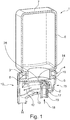
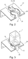
Es wird ein System vorgeschlagen aufweisend einen Dispenser mit einer Kartuschenhalterung (24) und einer Kartusche (1), wobei die Kartuschenhalterung (24) mindestens eine Führung und/oder Verdrehsicherung (25, 27) für eine Kartuschenaufnahme (10) aufweist, wobei an oder in der Kartuschenaufnahme (10) die Kartusche (1) vorgesehen ist, die einen Wandbereich (6) aufweist, an dessen einem Ende sich ein Verbindungsbereich (4) anschließt, der mit einer Membran (14) verschlossen ist und an dessen gegenüberliegendem Ende ein Bodenbereich (7) vorgesehen ist, wobei der Wandbereich (6) und der Bodenbereich (7) einen Hohlraum aufspannen, der ein Getränke- und/oder Lebensmittelsubstrat aufnimmt, dadurch gekennzeichnet, dass die Kartuschenaufnahme (10) ein Aufstechmittel (16) zum Perforieren der Membran (14) aufweist, wobei die Kartuschenaufnahme (10) eine Dornführung (28) aufweist, in welcher das Aufstechmittel (16) verschiebbar gelagert ist, wobei das Aufstechmittel (16) zwischen einer eingefahrenen Position, in welcher das Aufstechmittel (16) von der Membran (14) beabstandet ist, und einer ausgefahrenen Position, in welcher das Aufstechmittel (16) die Membran (14) der Kartusche (1) durchsticht und bis in die Kartusche (1) ragt, verschiebbar ist.A system is proposed comprising a dispenser with a cartridge holder (24) and a cartridge (1), the cartridge holder (24) having at least one guide and / or anti-rotation device (25, 27) for a cartridge holder (10), with or The cartridge (1) is provided in the cartridge receptacle (10) and has a wall area (6), at one end of which a connecting area (4) is connected, which is closed with a membrane (14) and at the opposite end is a bottom area (7) is provided, the wall area (6) and the floor area (7) spanning a cavity which receives a beverage and / or food substrate, characterized in that the cartridge receptacle (10) has a piercing means (16) for perforating the membrane (14), the cartridge receptacle (10) having a mandrel guide (28) in which the piercing means (16) is slidably mounted, the piercing means (16) being inserted between one Position in which the piercing means (16) is spaced from the membrane (14) and an extended position in which the piercing means (16) pierces the membrane (14) of the cartridge (1) and into the cartridge (1) protrudes, is movable.
Description
Die Erfindung betrifft einen Dispenser mit einer Kartuschenhalterung.The invention relates to a dispenser with a cartridge holder.
Solche Systeme sind aus dem Stand der Technik, beispielsweise aus
Der eingangs genannte Dispenser ist also aus dem Stand der Technik bekannt und wird dafür eingesetzt mittels Kartuschen beispielsweise Kaltgetränke herzustellen. Wichtig ist, dass die Kartusche sicher im dem Dispenser gehalten ist, so dass zum einen keinerlei Leckage zum anderen aber auch keine Rückkontamination stattfindet.The dispenser mentioned at the outset is therefore known from the prior art and is used for this purpose to produce, for example, cold drinks using cartridges. It is important that the cartridge is held securely in the dispenser so that there is no leakage on the one hand and no back-contamination on the other.
Es war deshalb die Aufgabe der vorliegenden Erfindung einen Dispenser zur Verfügung zu stellen, der diesen Anforderungen gerecht wird. Insbesondere solle eine leckagefreie Getränkeherstellung ohne Rückkontamination des Dispensers ermöglicht werden. Der Dispenser soll gleichzeitig einen hohen Bedienkomfort bieten und kostengünstig realisierbar sein. Eine weitere Aufgabe der vorliegenden Erfindung ist es, die Schaumbildung auf dem Getränk oder Lebensmittel kontrolliert einzustellen.It was therefore the object of the present invention to provide a dispenser that meets these requirements. In particular, leak-free beverage production should be made possible without recontamination of the dispenser. At the same time, the dispenser should offer a high level of operating convenience and be cost-effective to implement. Another object of the present invention is to control foam formation on the beverage or food in a controlled manner.
Gelöst wird die Ausgabe mit Dispenser mit einer Kartuschenhalterung, die mindestens eine Führung und/oder Verdrehsicherung für eine Kartusche und/oder eine Kartuschenaufnahme aufweist.The issue is solved with a dispenser with a cartridge holder which has at least one guide and / or anti-rotation device for a cartridge and / or a cartridge holder.
Die zu diesem Gegenstand der vorliegenden Erfindung gemachten Ausführungen gelten für die anderen Gegenstände der vorliegenden Erfindung gleichermaßen und umgekehrt.The statements made on this subject of the present invention apply equally to the other subjects of the present invention and vice versa.
Die vorliegende Erfindung betrifft einen Dispenser mit einer Kartuschenhalterung, die die Kartusche an dem Dispenser lagert und die Kartusche abstützt und/oder führt. Die Kartusche weist einen Hohlraum auf, in dem sich ein Getränke- und/oder Lebensmittelsubstrat befindet. Dieses Substrat ist vorzugsweise flüssig und insbesondere ein Konzentrat und wird mit einem Lösemittel, insbesondere Wasser, zur Herstellung des Getränks oder Lebensmittels gemischt und dann in einem Behälter, insbesondere einem Glas, das vorzugsweise auf einer unterhalb der Kartuschenhalterung angeordneten Auflage des Dispensers steht, aufgefangen. Das Getränke- und/oder Lebensmittelsubstrat umfasst vorzugsweise flüssige Pre-Mix-Bestandteile für Erfrischungsgetränke, wie koffein-, kohlensäure-, frucht- und/oder zuckerhaltige Limonaden und Säfte, Bier(misch)getränke oder sonstige alkoholische oder nicht alkoholische (Misch-)Getränke.The present invention relates to a dispenser with a cartridge holder, which supports the cartridge on the dispenser and supports and / or guides the cartridge. The cartridge has a cavity in which a beverage and / or food substrate is located. This substrate is preferably liquid and in particular a concentrate and is mixed with a solvent, in particular water, for the production of the beverage or food and then collected in a container, in particular a glass, which is preferably placed on a support of the dispenser arranged below the cartridge holder. The beverage and / or food substrate preferably comprises liquid pre-mix components for soft drinks, such as lemonades and juices containing caffeine, carbon dioxide, fruit and / or sugar, beer (mixed) drinks or other alcoholic or non-alcoholic (mixed) drinks. Beverages.
Erfindungsgemäß ist nun eine Führung und/oder Verdrehsicherung an der Kartuschenhalterung vorgesehen. Dadurch wird sichergestellt, dass die Kartusche zum einen zumindest bezüglich einer Raumrichtung eine bestimmte Lage relativ zu dem Dispenser einnimmt zum anderen wird verhindert, dass sich die Kartusche vor oder während der Herstellung des Getränks verdreht oder in einer falschen Orientierung eingesetzt wird. Auf diese Weise wird auch sichergestellt, dass falls die Kartusche mit einer Produktidentifikationskennung ausgestattet ist, welche von einem Kennungsdetektor des Dispensers auszulesen ist, die Kennung stets dem Detektor zugewandt ist, so dass ein zuverlässiges und fehlerfreies Auslesen ermöglicht wird.According to the invention, a guide and / or anti-rotation device is now provided on the cartridge holder. This ensures that, on the one hand, the cartridge assumes a certain position relative to the dispenser, at least with respect to a spatial direction, on the other hand, it prevents the cartridge from twisting before or during the production of the beverage or from being inserted in the wrong orientation. In this way it is also ensured that if the cartridge is equipped with a product identification code which can be read out by an identification detector of the dispenser, the identification always faces the detector, so that a reliable and error-free reading is made possible.
Vorzugsweise weist die Kartuschenhalterung eine Ausnehmung auf, die die Kartusche und/oder die Kartuschenaufnahme zumindest teilweise aufnimmt. Vorzugsweise wirken die Ausnehmung in der Kartuschenhalterung und die Kartusche oder Kartuschenaufnahme zumindest teilweise formschlüssig zusammen und wirken so als Auflager und/oder Verdrehsicherung. Vorzugsweise erstreckt sich die Ausnehmung bis zum Rand, so dass der Umfang der Ausnehmung an einer Stelle offen ist. Dort kann die Ausbuchtung in der Kartuschenaufnahme platziert werden. Alternativ weist die Ausnehmung eine Ausbuchtung für die Ausbuchtung an der Kartuschenaufnahme auf.The cartridge holder preferably has a recess which at least partially receives the cartridge and / or the cartridge receptacle. The recess in the cartridge holder and the cartridge or cartridge receptacle preferably interact at least partially in a form-fitting manner and thus act as a support and / or anti-rotation device. The recess preferably extends to the edge, so that the periphery of the recess is open at one point. The bulge can be placed there in the cartridge holder. Alternatively, the recess has a bulge for the bulge on the cartridge holder.
Alternativ oder zusätzlich weist die Kartuschenhalterung eine Führung auf, die mit dem Umfang der Kartuschenaufnahme und/oder die Kartusche zusammenwirkt. Diese Führung kann beispielsweise ein Stehkragen sein, der sich vorzugsweise im Randbereich der Ausnehmung in der Kartuschenhalterung erstreckt. Die Führung erstreckt sich vorzugsweise in einem rechten Winkel zu der Horizontalen und verhindert ein Kippen der Kartusche relativ zu der Vertikalen.Alternatively or additionally, the cartridge holder has a guide which interacts with the circumference of the cartridge receptacle and / or the cartridge. This guide can be, for example, a stand-up collar, which preferably extends in the edge region of the recess in the cartridge holder. The guide preferably extends at a right angle to the horizontal and prevents the cartridge from tilting relative to the vertical.
Gemäß einer bevorzugten Ausführungsform weisen die Ausnehmung und/oder die Führung eine Öffnung für einen Vorsprung/Ausbuchtung an der Kartuschenaufnahme auf, der als Verdrehsicherung oder als zusätzliche Stabilisierung wirken kann.According to a preferred embodiment, the recess and / or the guide have an opening for a projection / bulge on the cartridge receptacle, which can act as an anti-rotation device or as additional stabilization.
Vorzugsweise weist die Kartuschenhalterung einen Flüssigkeitsanschluss auf. Mit diesem Flüssigkeitsanschluss wird das Lösemittel zur Herstellung des Getränks zur Verfügung gestellt. Der Flüssigkeitsanschluss der Kartuschenhalterung wird vorzugsweise mit dem Flüssigkeitszulauf in der Kartuschenaufnahme, insbesondere flüssigkeitsdicht, in Verbindung gebracht. Gemäß einer weiteren bevorzugten Ausführungsform der vorliegenden Erfindung ist vorgesehen, dass der Flüssigkeitsanschluss mit Fluid gespeist wird, welches durch ein Kühlaggregat gekühlt wird, wobei das Kühlaggregat Teil des Dispensers oder eines mit dem Dispenser in Wirkverbindung stehenden separaten Kühlschranks ist. In vorteilhafter Weise sind somit Kaltgetränke herstellbar, auch wenn die Kartusche selbst nicht gekühlt ist und beispielweise Zimmertemperatur aufweist. Die Integration des Systems in einen bestehenden Kühlschrank hat den Vorteil, dass das bestehende Kühlaggregat des Kühlschranks für den Dispenser in effizienter Weise einfach mitgenutzt werden kann. Insbesondere bei sogenannten "side-by-side"-Kühlschränken (oft auch als amerikanische Kühlschränke bezeichnet) findet sich in der Front ausreichend Bauraum zur Integration des Dispensers. Denkbar ist, dass es sich bei dem Dispenser um ein Nachrüstset für einen solchen Kühlschrank handelt. Das Kühlaggregat umfasst vorzugsweise eine Kompressorkühleinheit, eine Absorberkühleinheit oder einen thermoelektrischen Kühler. Gemäß einer weiteren bevorzugten Ausführungsform der vorliegenden Erfindung ist vorgesehen, dass der Flüssigkeitsanschluss mit Fluid gespeist wird, welches durch einen Karbonisierer mit Kohlensäure versetzt wird. Denkbar ist, dass der Karbonisierer Teil des Dispensers ist und wobei der Karbonisierer eine Aufnahme für eine CO2-Patrone und eine Zuführeinrichtung zum Versetzen des Fluides mit CO2 aus der CO2-Patrone aufweist. Vorteilhafterweise lassen sich mit dem System somit auch mit Kohlensäure versetzte (Erfrischungs-) Getränke herstellen. Alternativ wäre auch denkbar, dass der Karbonisierer einen externen CO2-Anschluss aufweist. Das Fluid umfasst insbesondere Wasser, welches aus einer Wasserleitung oder einem Wassertank des Dispensers mittels einer oder mehrerer Pumpen, vorzugsweise Membranpumpen, bereitgestellt wird. Die Förderung des Wassers zum Flüssigkeitsanschluss wird vorzugsweise mittels eines Durchflusssensors, beispielsweise einem Ultraschalldurchflusssensor oder einem magnetisch-induktivem Durchflusssensor, überwacht.The cartridge holder preferably has a liquid connection. This liquid connection provides the solvent for the production of the drink. The liquid connection of the cartridge holder is preferably connected to the liquid inlet in the cartridge receptacle, in particular in a liquid-tight manner. According to a further preferred embodiment of the present invention, it is provided that the liquid connection is fed with fluid which is cooled by a cooling unit, the cooling unit being part of the dispenser or of a separate refrigerator which is operatively connected to the dispenser. Cold drinks can thus be produced in an advantageous manner, even if the cartridge itself is not cooled and has, for example, room temperature. The integration of the system into an existing refrigerator has the advantage that the existing cooling unit of the refrigerator can be used easily and efficiently for the dispenser. In particular with so-called "side-by-side" refrigerators (often also referred to as American refrigerators), there is sufficient installation space in the front for integrating the dispenser. It is conceivable that the dispenser is a retrofit kit for such a refrigerator. The cooling unit preferably comprises a compressor cooling unit, an absorber cooling unit or a thermoelectric cooler. According to a further preferred embodiment of the present invention, it is provided that the liquid connection is fed with fluid which is carbonated by a carbonizer. It is conceivable that the carbonizer is part of the dispenser and the carbonizer has a receptacle for a CO2 cartridge and a feed device for adding the CO2 from the CO2 cartridge to the fluid. Advantageously, the system can also be used to produce carbonated (refreshing) beverages. Alternatively, it would also be conceivable for the carbonator to have an external CO2 connection. The fluid particularly comprises water, which consists of a Water pipe or a water tank of the dispenser is provided by means of one or more pumps, preferably membrane pumps. The conveyance of the water to the liquid connection is preferably monitored by means of a flow sensor, for example an ultrasonic flow sensor or a magnetic-inductive flow sensor.
Erfindungsgemäß ist vorgesehen, dass die Kartuschenhalterung einen mit einer Druckluftquelle verbundenen Druckluftauslass aufweist. Der Druckluftauslass fungiert als Kartuschenentladeeinrichtung und dient dazu, Druckluft von außen in den Hohlraum der Kartusche einzuleiten, wodurch das Lebensmittel- und/oder Getränkesubstrat aus dem Hohlraum in eine Mischkammer der Kartuschenaufnahme zu drücken. Die Druckluft wird insbesondere von dem Dispenser bereitgestellt. Die Kartuschenaufnahme weist vorzugsweise einen Gaseinlass auf, welcher beim Einsetzen der Kartuschenaufnahme in die Kartuschenhalterung direkt an den Druckluftauslass der Kartuschenhalterung angekoppelt wird. Dies hat den Vorteil, dass eine Rückkontamination in Richtung des Dispenser wirksam vermieden wird, weil der Druckkanal sofort beim Einsetzen des Kartuschensystems in die Kartuschenhalterung unter Druck steht und somit verhindert wird, dass Lebensmittelund/oder Getränkesubstrat in Richtung des Dispensers und insbesondere in Richtung der Druckluftquelle wandert. Das Substrat kann sich ausgehend von dem Hohlraum in der Kartusche somit lediglich in Richtung der Mischkammer bewegen.According to the invention, it is provided that the cartridge holder has a compressed air outlet connected to a compressed air source. The compressed air outlet acts as a cartridge unloading device and serves to introduce compressed air from the outside into the cavity of the cartridge, as a result of which the food and / or beverage substrate is pressed out of the cavity into a mixing chamber of the cartridge receptacle. The compressed air is provided in particular by the dispenser. The cartridge receptacle preferably has a gas inlet which is coupled directly to the compressed air outlet of the cartridge holder when the cartridge receptacle is inserted into the cartridge holder. This has the advantage that back-contamination in the direction of the dispenser is effectively avoided because the pressure channel is immediately under pressure when the cartridge system is inserted into the cartridge holder and thus prevents food and / or beverage substrates from being directed towards the dispenser and in particular towards the compressed air source wanders. Starting from the cavity in the cartridge, the substrate can thus only move in the direction of the mixing chamber.
Gemäß einer weiteren bevorzugten Ausführungsform der vorliegenden Erfindung ist vorgesehen, dass die Kartuschenhalterung ein Auslöseelement aufweist, um ein Aufstechmittel der Kartuschenaufnahme von einer eingefahrenen Position in eine ausgefahrene Position zu überführen. Die Kartusche ist vorzugsweise mit einer Membran, beispielsweise eine Dichtfolie, verschlossen. Die Kartuschenaufnahme weist vorzugsweise ein Aufstechmittel auf, welches zwischen einer eingefahrenen Position, in welcher das Aufstechmittel von der Membran beabstandet ist, und einer ausgefahrenen Position, in welcher das Aufstechmittel die Membran durchsticht und bis in den Hohlraum ragt, verschiebbar ist. Die Kartusche wird also von dem Aufstechmittel geöffnet. Zur Überführung des Aufstechmittels in die ausgefahrene Position weist die Kartuschenhalterung das Auslöseleement auf. Denkbar ist, dass das Auslöseelement einen feststehenden Vorsprung umfasst, der beim Einsetzen des Kartuschensystems in die Kartuschenhalterung in Anlage mit dem Aufstechmittel gelangt und das Aufstechmittel durch eine Relativbewegung zwischen Kartuschensystem und Auslöseelement in die ausgefahrene Position treibt. Besonders bevorzugt ist in das Aufstechmittel der Druckluftauslass integriert.According to a further preferred embodiment of the present invention, it is provided that the cartridge holder has a release element in order to transfer a piercing means of the cartridge receptacle from a retracted position to an extended position. The cartridge is preferably closed with a membrane, for example a sealing film. The cartridge receptacle preferably has a piercing means which can be displaced between a retracted position in which the piercing means is spaced from the membrane and an extended position in which the piercing means pierces the membrane and protrudes into the cavity. The cartridge is thus opened by the piercing means. The cartridge holder has the release element for transferring the piercing means into the extended position. It is conceivable that the trigger element comprises a fixed projection which comes into contact with the piercing means when the cartridge system is inserted into the cartridge holder and which drives the piercing means into the extended position by means of a relative movement between the cartridge system and the trigger element. The compressed air outlet is particularly preferably integrated into the piercing means.
Vorzugsweise umfasst die Kartuschenhalterung einen Befestigungsflansch umfasst, welcher die Kartuschenaufnahme beim oder nach dem Einsetzen in den Halter formschlüssig und/oder kraftschlüssig umgreift. Der Befestigungsflansch umfasst ferner eine Auslösemechanik, die derart konfiguriert ist, dass eine Betätigung der Auslösemechanik zu einem Umgreifen der Kartuschenaufnahme durch den Befestigungsflansch und/oder zu einem Verschieben des Befestigungsflansches derart, dass eine Relativbewegung zwischen Kartuschenaufnahme und dem in Kontakt mit dem Aufstechmittel stehenden Auslöseelement erzeugt wird, wodurch das Aufstechmittel von der eingefahrenen Position in die ausgefahrene Position überführt wird, führt. Die Auslösemechanik umfasst insbesondere einen Handhebel zur manuellen Betätigung derselben umfasst, wobei vorzugsweise der Handhebel um eine zur Längsachse der Kartusche im Wesentlichen parallele Drehachse drehbar ausgebildet ist. Ferner umfasst die Auslösemechanik vorzugsweise ein Übersetzungsgetriebe, welche eine Drehbewegung des Handhebels um die zur Längsachse parallele Drehachse in eine zur Längsachse im Wesentlichen parallele Translationsbewegung übersetzt. Nachdem das Kartuschensystem in die Kartuschenhalterung eingesetzt wurde, wird der Handhebel durch den Benutzer betätigt, wodurch das Kartuschensystem fest umgriffen und linear gegen das Auslöseelement verschoben wird. Durch die Verdrehsicherung und die Übersetzung der Drehbewegung in die lineare Translationsbewegung wird sichergestellt, dass die Ortientierung der Kartusche relativ zum Dispenser konstant bleibt. Hierdurch wird vorteilhafterweise das im Folgenden beschriebene ein Auslesen der Produktidentifikationskennung vereinfacht.The cartridge holder preferably comprises a fastening flange which engages around the cartridge receptacle in a form-fitting and / or non-positive manner when or after insertion into the holder. The fastening flange further comprises a trigger mechanism that is configured such that actuation of the trigger mechanism to encompass the cartridge receptacle through the fastening flange and / or to move the fastening flange such that a relative movement between the cartridge receptacle and the trigger element that is in contact with the piercing means produces is, whereby the piercing means is transferred from the retracted position to the extended position. The trigger mechanism comprises in particular a hand lever for manual actuation thereof, the hand lever preferably being designed to be rotatable about an axis of rotation substantially parallel to the longitudinal axis of the cartridge. Furthermore, the trigger mechanism preferably comprises a transmission gear, which translates a rotary movement of the hand lever about the axis of rotation parallel to the longitudinal axis into a translation movement essentially parallel to the longitudinal axis. After the cartridge system has been inserted into the cartridge holder, the hand lever is actuated by the user, as a result of which the cartridge system is firmly gripped and linearly displaced against the release element. The anti-rotation device and the translation of the rotary movement into the linear translation movement ensure that the orientation of the cartridge relative to the dispenser remains constant. This advantageously simplifies the reading of the product identification identifier described below.
Gemäß einer weiteren bevorzugten Ausführungsform der vorliegenden Erfindung ist vorgesehen, dass der Dispenser einen Kennungsdetektor zum Auslesen einer Produktidentifikationskennung auf der Kartusche und/oder der Kartuschenaufnahme aufweist, wobei der Kennungsdetektor vorzugsweise oberhalb und/oder hinter dem Halter angeordnet ist. Vorzugsweise ist die Produktidentifikationskennung in einen Barcode, einen RFID-Code, einen QR-Code, einen Data-Matrix-Code, einen Farbcode, einen Hologrammcode oder dergleichen eingebettet. In vorteilhafter Weise wird somit ein automatisches Auslesen der Produktidentifikationskennung möglich. Der Kennungsdetektor umfasst insbesondere einen optischen Sensor, wie beispielsweise eine CCD-Kamera, welche den Barcode oder QR-Code oder Data-Matrix-Code automatisch ausliest, wenn die Kartusche in die Getränkezubereitungsmaschine eingesetzt ist. Alternativ umfasst der Kennungsdetektor eine Sende- und Empfangsantenne zum automatischen Auslesen der RFID-Codes. Alternativ wäre denkbar, dass die Produktidentifikationskennung auch in andere automatisch auslesbare Computerchips eingebettet wird. Der Begriff QR-Code umfasst im Sinne der vorliegenden Erfindung insbesondere jedweden Data-Matrix-Code.According to a further preferred embodiment of the present invention, it is provided that the dispenser has an identification detector for reading out a product identification identification on the cartridge and / or the cartridge holder, the identification detector preferably being arranged above and / or behind the holder. The product identification identifier is preferably embedded in a bar code, an RFID code, a QR code, a data matrix code, a color code, a hologram code or the like. This advantageously makes it possible to automatically read out the product identification identifier. The identification detector comprises, in particular, an optical sensor, such as a CCD camera, which automatically reads the barcode or QR code or data matrix code when the cartridge is inserted into the beverage preparation machine. Alternatively, the identification detector comprises a transmitting and receiving antenna for automatically reading out the RFID codes. Alternatively, it would be conceivable that the product identification identifier is also embedded in other automatically readable computer chips. For the purposes of the present invention, the term QR code includes in particular any data matrix code.
Insofern werden die Begriff QR-Code und Data-Matrix-Code synonym verwendet. Alternativ oder zusätzlich wäre auch denkbar, dass die Produktidentifikationskennung einen Strichcode, einen Punktcode, einen Binärcode, einen Morsecode, Braillezeichencode (Blindenschrift) oder dergleichen umfasst. Der Code kann dabei auch in eine dreidimensionale Struktur, wie beispielweise ein Relief eingebettet sein. Die Produktidentifikationskennung umfasst insbesondere die sogenannte Produktidentifikationsnummer, insbesondere einen Universal Product Code (UPC), eine European Article Number (EAN), einen GS1-Code, eine Global Trade Item Number (GTIN) oder dergleichen. Auf diese Weise braucht hierfür kein neues Codesystem eingeführt werden. Insbesondere läuft die Produktidentifikationskennung unter dem GS1-Standard. Die Produktidentifikationskennung ist vorzugsweise direkt auf die Kartusche gedruckt, geklebt und/oder in die Oberfläche der Kartusche eingebracht, bspw. durch eine (Laser-)Gravur, Stanzen oder direkt bei der Herstellung der Kartusche. Alternativ wäre auch denkbar, dass die Kartusche mit einem Überzug, beispielsweise einem Sleeve, zumindest teilweise umhüllt wird, auf welchem die Produktidentifikationskennung angeordnet ist. Der Überzug kann mit der Kartusche auch verklebt oder verschweißt sein. Der Überzug oder das Sleeve könnten aus einer Kunststofffolie, einem Textil oder Papier hergestellt sein.In this respect, the terms QR code and data matrix code are used synonymously. Alternatively or additionally, it would also be conceivable that the product identification identifier comprises a bar code, a point code, a binary code, a Morse code, Braille character code (Braille) or the like. The code can also be embedded in a three-dimensional structure, such as a relief. The product identification identifier includes in particular the so-called product identification number, in particular a universal product code (UPC), a European Article Number (EAN), a GS1 code, a global trade item number (GTIN) or the like. In this way, no new code system needs to be introduced for this. In particular, the product identification code runs under the GS1 standard. The product identification identifier is preferably printed directly on the cartridge, glued and / or introduced into the surface of the cartridge, for example by (laser) engraving, punching or directly during the manufacture of the cartridge. Alternatively, it would also be conceivable for the cartridge to be at least partially covered with a covering, for example a sleeve, on which the product identification identifier is arranged. The cover can also be glued or welded to the cartridge. The cover or sleeve could be made of a plastic film, a textile or paper.
Ein weiterer oder bevorzugter Gegenstand der vorliegenden Erfindung ist ein Dispenser, der eine Auflage für einen Behälter aufweist, im dem das fertiggestellte Getränk oder Lebensmittel aufgefangen wird, wobei die Auflage höhenverstellbar und/oder schwenkbar vorgesehen ist.Another or preferred object of the present invention is a dispenser which has a support for a container in which the finished beverage or food is collected, the support being provided adjustable in height and / or pivotable.
Vorzugsweise ist die Auflage, beispielsweise um eine Achse oder um einen Punkt so schwenkbar vorgesehen, dass der Behälter, insbesondere beim Zustrom des fertiggestellten Getränks oder des Lebensmittels schräg gestellt werden kann. Dadurch ist es möglich, die Schaumbildung auf dem Getränk zu beeinflussen. Die Auflage kann manuell oder motorisch verstellt werden. Der Dispenser kann ein Mittel, beispielsweise eine Kamera aufweisen, die den Schaumstand auf dem Getränk oder Lebensmittel ermittelt und anhand des Signals dieses Mittels die Schrägstellung entsprechend verändert wird. Weiterhin bevorzugt kann die Kartusche, die zur Herstellung des Getränks oder Lebensmittels eingesetzt wird eine Information über die einzusetzende Schrägstellung aufweisen. Gemäß noch einer weiteren bevorzugten Ausführungsform weist die Kartusche eine Kennung auf, anhand derer sie identifiziert werden kann. Sobald die Kartusche erkannt ist, sind Informationen über die gewünschte Schrägstellung des Behälters abrufbar. Analoges gilt für den Behälter, in dem das Getränk oder Lebensmittel aufgefangen wird. Auch dieses kann Informationen und/oder eine Kennung aufweisen, mit denen die gewünschte Schrägstellung ermittelbar ist. Weiterhin ist die Auflage vorzugsweise höhenverstellbar, so dass die Auflage beispielsweise an unterschiedliche Glasgrößen anpassbar ist und/oder die Schaumbildung durch die Länge der Fallstrecke beeinflussbar ist.The support is preferably provided so that it can pivot, for example about an axis or about a point, in such a way that the container can be tilted, in particular when the finished beverage or food flows in. This makes it possible to influence the foam formation on the drink. The pad can be adjusted manually or by motor. The dispenser can have a means, for example a camera, which determines the foam level on the beverage or food and, based on the signal of this means, changes the inclination accordingly. Furthermore, the cartridge that is used to produce the beverage or food can preferably have information about the inclination to be used. According to yet another preferred embodiment, the cartridge has an identifier by means of which it can be identified. As soon as the cartridge is recognized, information about the desired inclination of the container can be called up. The same applies to the container in which the drink or food is collected. This can also have information and / or an identifier with which the desired inclination can be determined. Farther the support is preferably adjustable in height, so that the support can be adapted, for example, to different glass sizes and / or the foam formation can be influenced by the length of the drop distance.
Des Weiteren betrifft die vorliegende Erfindung ein System mit einer Kartuschenaufnahme und/oder einer Kartusche, wobei die Kartuschenaufnahme die Kartusche reversibel oder irreversibel insbesondere teilweise aufnimmt. Die Kartusche hat einen Hohlraum, in dem sich die Getränke- und/oder Lebensmittelsubstanz befindet und die vor der Getränke- und/oder Lebensmittelherstellung, insbesondere durch die Membran, hermetisch verschlossen ist. Zur Herstellung des Getränks und/oder Lebensmittels wird die Kartusche dann geöffnet, insbesondere wird die Membran aufgestochen, und das Substrat läuft/strömt, insbesondere unterstützt durch Einleiten von Druckluft in den Hohlraum, in eine Mischkammer der Kartuschenaufnahme, die auch über einen Zulauf für ein Verdünnungsmittel (auch als Lösungsmittel bezeichnet), insbesondere Wasserzulauf, verfügt, das mit dem Substrat gemischt wird, um das fertige Getränk oder Lebensmittel zu erzeugen, das durch einen ebenfalls an der Kartuschenaufnahme vorgesehenen Ablauf aus der Mischkammer herausläuft. Der Volumenstrom des Lösungsmittels ist dabei in der Regel wesentlich größer als der Volumenstrom des Substrats. Die Kartusche und die mit der Kartusche verbundene Kartuschenaufnahme bilden zusammen ein Kartuschensystem, welches in die Kartuschenhalterung des Dispensers einsetzbar ist.Furthermore, the present invention relates to a system with a cartridge receptacle and / or a cartridge, the cartridge receptacle receiving the cartridge reversibly or irreversibly, in particular partially. The cartridge has a cavity in which the beverage and / or food substance is located and which is hermetically sealed before the beverage and / or food production, in particular by the membrane. To produce the beverage and / or food, the cartridge is then opened, in particular the membrane is pierced, and the substrate runs / flows, in particular supported by introducing compressed air into the cavity, into a mixing chamber of the cartridge receptacle, which also has an inlet for a Diluent (also referred to as solvent), in particular water inlet, which is mixed with the substrate in order to produce the finished beverage or food which runs out of the mixing chamber through an outlet also provided on the cartridge receptacle. The volume flow of the solvent is usually much larger than the volume flow of the substrate. The cartridge and the cartridge receptacle connected to the cartridge together form a cartridge system which can be inserted into the cartridge holder of the dispenser.
Vorzugsweis ist der Strömungsquerschnitt, d.h. der Querschnitt, der für Strömung der Flüssigkeit, insbesondere des Lösungsmittelstroms und/oder des Gemischs aus Lösungsmittel und Substrat zur Verfügung steht, nun so vorgesehen, dass sich bezogen auf die Strömungsrichtung des Lösungsmittels die Strömungsgeschwindigkeit zunächst verlangsamt und dann wieder beschleunigt. Die Beschleunigung, die durch eine Strömungsquerschnittsverengung erreicht wird, findet möglichst statt, nachdem das Lösungsmittel und das Substrat vermischt worden sind.The flow cross-section is preferred, i.e. the cross section, which is available for the flow of the liquid, in particular the solvent flow and / or the mixture of solvent and substrate, is now provided in such a way that the flow velocity initially slows down and then accelerates again, based on the direction of flow of the solvent. The acceleration, which is achieved by a narrowing of the flow cross-section, takes place after the solvent and the substrate have been mixed.
Gemäß einem weiteren bevorzugten Gegenstand der vorliegenden Erfindung weist die Mischkammer eine Ausbuchtung auf. Diese Ausbuchtung ragt vorzugsweise aus dem Umfang, insbesondere dem seitlichen Umfang, der sich zwischen den beiden Stirnseiten der Kartuschenaufnahme erstreckt, heraus. Vorzugsweise ist die Ausbuchtung Teil der Mischkammer. Vorzugsweise ist der Umfang der Mischkammer im Wesentlichen kreisförmig gestaltet und die Ausbuchtung rang aus dieser Kreisform heraus. Gemäß einer besonders bevorzugten Ausführungsform der vorliegenden Erfindung ist der Ablauf des fertiggestellten Getränks oder Lebensmittels in der Ausbuchtung vorgesehen.According to a further preferred object of the present invention, the mixing chamber has a bulge. This bulge preferably protrudes from the circumference, in particular the lateral circumference, which extends between the two end faces of the cartridge receptacle. The bulge is preferably part of the mixing chamber. The circumference of the mixing chamber is preferably essentially circular and the bulge protrudes from this circular shape. According to a particularly preferred embodiment of the present invention, the discharge of the finished drink or food is provided in the bulge.
Gemäß noch einem bevorzugten Gegenstand der vorliegenden Erfindung weist die Kartuschenaufnahme einen Befestigungs- und/oder Sicherungsring aufweist. Dieser Befestigungs- und/oder Sicherungsring nimmt vorzugsweise die Kartusche, die an der Kartuschenaufnahme befestigt wird, auf. Vorzugsweise ist der Befestigungs- und/oder Sicherungsring mit einer Sollbruch- und/oder Solldeformationsstelle an der Mischkammer vorgesehen. Vor der Herstellung eines Getränks oder Lebensmittels wird diese Stelle zerstört und oder verformt, insbesondere irreversibel verformt. Dies kann beispielsweise durch eine Bewegung der Kartusche und der Kartuschenaufnahme relativ zueinander erfolgen. Durch die Deformation und/oder Zerstörung kann die Kartuschenaufnahme nur einmal benutzt werden und/oder der Verbund zwischen der Kartuschenaufnahme und der Kartusche kann nicht mehr gelöst werden.According to yet another preferred object of the present invention, the cartridge receptacle has a fastening and / or locking ring. This fastening and / or locking ring preferably receives the cartridge that is attached to the cartridge receptacle. The fastening and / or securing ring is preferably provided on the mixing chamber with a predetermined breaking and / or predetermined deformation point. Before a beverage or food is produced, this point is destroyed and or deformed, in particular irreversibly deformed. This can be done, for example, by moving the cartridge and the cartridge holder relative to one another. Due to the deformation and / or destruction, the cartridge holder can only be used once and / or the bond between the cartridge holder and the cartridge can no longer be released.
Vorzugsweise ist in der Mischkammer mindestens ein Mischelement vorgesehen, das für eine Verwirbelung des Lösemittels oder des Gemischs von Lösemittel und Substrat sorgt. Vorzugsweise ist das Mischelement als Ausbuchtung und/oder Anformung im Boden der Mischkammer vorgesehen. Vorzugsweise ist das Mischelement so gestaltet, dass Kohlensäure, die in dem Lösemittel gelöst ist, nicht oder nur geringfügig ausgast. Vorzugsweise ist das Mischelement so gestaltet, das es nur einen geringen Druckverlust aufweist.Preferably, at least one mixing element is provided in the mixing chamber, which ensures swirling of the solvent or the mixture of solvent and substrate. The mixing element is preferably provided as a bulge and / or molding in the bottom of the mixing chamber. The mixing element is preferably designed in such a way that carbonic acid, which is dissolved in the solvent, does not outgass or only outgas slightly. The mixing element is preferably designed in such a way that it has only a low pressure drop.
Vorzugsweise weist die Kartuschenaufnahme ein Aufstechmittel auf, dass die Membran vor der Herstellung des Getränks oder Lebensmittels perforiert. Dieses Aufstechmittel ist beispielsweise als Dorn gestaltet, der aus dem Boden der Mischkammer ragt. Die Kartuschenaufnahme weist vorzugsweise eine Dornführung auf, in welcher das Aufstechmittel verschiebbar gelagert ist. Das Aufstechmittel ist auf diese Weise zwischen einer eingefahrenen Position, in welcher das Aufstechmittel von der Membran beabstandet ist, und einer ausgefahrenen Position, in welcher das Aufstechmittel die Membran durchsticht und bis in den Hohlraum der Kartusche ragt, verschiebbar.The cartridge receptacle preferably has a piercing means that perforates the membrane before the beverage or food is produced. This piercing means is designed, for example, as a mandrel that protrudes from the bottom of the mixing chamber. The cartridge receptacle preferably has a mandrel guide in which the piercing means is slidably mounted. In this way, the piercing means can be displaced between a retracted position in which the piercing means is spaced from the membrane and an extended position in which the piercing means pierces the membrane and protrudes into the cavity of the cartridge.
Vorzugsweise weist das Aufstechmittel an seinem äußeren Umfang mindestens eine, vorzugsweise mehrere Ein- und/oder Ausbuchtungen auf, die als Ablauf für das Substrat dienen. Die Menge und die Größe der Ein- und/oder Ausbuchtungen hängt vorzugsweise von der Viskosität des Substrats ab. Die Außenwandung des Aufstechmittels ist also mit wenigstens einem Seitenkanal zum Leiten des Substrats in Richtung der Mischkammer, wenn die Membran durchstochen ist, versehen. Durch den seitlich am Aufstechmittel ausgebildeten Seitenkanal kann das Substrat dann an der Membran vorbei in Richtung Mischkammer fließen. Vorzugsweise sind eine Mehrzahl von Seitenkanälen am Aufstechmittel ausgebildet. Die Seitenkanäle sind insbesondere jeweils in Form einer einseitig offenen Nut ausgebildet. Denkbar ist, dass der Querschnitt der Seitenkanäle und/oder die Anzahl der Seitenkanäle an die Viskosität des Substrats angepasst ist, so dass die Seitenkanäle den Fluss des Substrats in Richtung Mischkammer kontrollieren bzw. begrenzen. Bei einer hohen Viskosität werden mehrere Seitenkanäle oder Seitenkanäle mit größerem Querschnitt verwendet, während bei einer niedrigeren Viskosität weniger Seitenkanäle oder Seitenkanäle mit geringerem Querschnitt vorgesehen sind. Für jede Kartusche existiert somit eine passende Kartuschenaufnahme.The piercing means preferably has at least one, preferably a plurality of indentations and / or bulges on its outer circumference, which serve as a drain for the substrate. The amount and size of the indentations and / or bulges preferably depends on the viscosity of the substrate. The outer wall of the piercing means is therefore provided with at least one side channel for guiding the substrate in the direction of the mixing chamber when the membrane is pierced. Through the side of the piercing device trained side channel, the substrate can then flow past the membrane in the direction of the mixing chamber. A plurality of side channels are preferably formed on the piercing means. The side channels are in particular each in the form of a groove open on one side. It is conceivable that the cross section of the side channels and / or the number of side channels is adapted to the viscosity of the substrate, so that the side channels control or limit the flow of the substrate in the direction of the mixing chamber. With a high viscosity, several side channels or side channels with a larger cross section are used, while with a lower viscosity fewer side channels or side channels with a smaller cross section are provided. There is a suitable cartridge holder for each cartridge.
Vorzugsweise ist in das Aufstechmittel eine Druckluftleitung, insbesondere in Form eines inneren Kanals, integriert, wobei an einer der Kartusche abgewandten Seite des Aufstechmittels ein, insbesondere von außerhalb der Kartuschenaufnahme zugänglicher Druckluftanschluss der Druckluftleitung zur Verbindung mit einer Druckluftquelle ausgebildet ist und wobei an einer dem Hohlraum der Kartusche zugewandten Seite des Aufstechmittels ein Druckluftausgang der Druckluftleitung zum Einblasen der Druckluft in die Kartusche ausgebildet ist. Vorzugsweise wird bereits beim Einsetzen des Kartuschensystems aus Kartusche und Kartuschenaufnahme in die Kartuschenhalterung bereits Druckluft an den Druckluftanschluss angelegt, um eine etwaige Rückkontamination des Dispensers zu verhindern. Alternativ wird das Aufstechmittel durch die über den Dispenser angelegte Druckluft von der eingefahrenen Position in die ausgefahrene Position verfahren. Anstelle von Druckluft kann auch CO2 in den Hohlraum eingeleitet werden, um das Substrat von dem Hohlraum in die Mischkammer zu überführen.Preferably, a compressed air line, in particular in the form of an inner channel, is integrated into the piercing means, a compressed air connection of the compressed air line, in particular from the outside of the cartridge receptacle, of the compressed air line for connection to a compressed air source being formed on one side of the piercing means and one of the cavities a side of the piercing means facing the cartridge is formed with a compressed air outlet of the compressed air line for blowing the compressed air into the cartridge. Compressed air is preferably already applied to the compressed air connection when the cartridge system consisting of cartridge and cartridge receptacle is inserted into the cartridge holder, in order to prevent possible back contamination of the dispenser. Alternatively, the piercing means is moved from the retracted position to the extended position by the compressed air applied via the dispenser. Instead of compressed air, CO2 can also be introduced into the cavity in order to transfer the substrate from the cavity into the mixing chamber.
Vorzugsweise weist das Aufstechmittel also einen Kanal auf, der in oder im Bereich der Spitze endet. Durch diesen Kanal kann ein Gas, insbesondere Luft oder CO2 in die Kartusche geblasen werden, um die Abgabe des Substrats zu beschleunigen und/oder zu dosieren.The piercing means therefore preferably has a channel which ends in or in the region of the tip. A gas, in particular air or CO 2, can be blown into the cartridge through this channel in order to accelerate and / or dose the delivery of the substrate.
Das System ist vorzugsweise derart ausgebildet, dass eine Kopplung des Druckluftanschlusses mit dem Druckluftauslass der Kartuschenhalterung erfolgt, wenn die Kartuschenaufnahme in die Kartuschenhalterung eingesetzt ist und/oder die Auslösemechanik für den Befestigungsflansch betätigt wird. Die Druckluftleitung wird somit frühestmöglich unter Druck gesetzt, so dass eine Rückkontamination des Dispensers durch das Substrat unterbunden wird.The system is preferably designed such that the compressed air connection is coupled to the compressed air outlet of the cartridge holder when the cartridge holder is inserted into the cartridge holder and / or the triggering mechanism for the fastening flange is actuated. The compressed air line is thus pressurized as early as possible, so that back contamination of the dispenser by the substrate is prevented.
Vorzugsweise sind der Zulauf und der Ablauf an gegenüberliegenden Enden der Kartuschenaufnahme vorgesehen. Besonders bevorzugt ist das Aufstechmittel in einer Flucht mit dem Zulauf und dem Ablauf vorgesehen.The inlet and the outlet are preferably provided at opposite ends of the cartridge holder. The piercing means is particularly preferably provided in alignment with the inlet and outlet.
Gemäß einem weiteren bevorzugten Gegenstand der vorliegenden Erfindung ist der Auslauf beweglich, insbesondere schwenkbar, an der Mischkammer vorgesehen oder weist ein Mittel auf, mit dem der Auslauf ausgerichtet, insbesondere in Richtung der Seitenwand des Gefäßes, das das fertiggestellte Getränk oder Lebensmittel aufnimmt, werden kann. Diese Ausführungsform ist insbesondere bei Getränken oder Lebensmitteln, die zu Schaumbildung neigen vorteilhaft. Das Bewegen des Auslaufs kann manuell oder motorisch erfolgen. Für den Fall, dass die Kartusche eine Identifikation aufweist, kann das Schwenken automatisch erfolgen, nachdem der Dispenser die Kartusche erkannt hat. Weiterhin kann ein Mittel vorhanden sein, dass den Schaum bestimmt. Basierend auf dieser Analyse kann dann die Einstellung des Auslaufs erfolgen.According to a further preferred object of the present invention, the spout is movable, in particular pivotable, provided on the mixing chamber or has a means with which the spout can be aligned, in particular in the direction of the side wall of the vessel which holds the finished beverage or food . This embodiment is particularly advantageous for beverages or foods that tend to foam. The spout can be moved manually or by motor. In the event that the cartridge has an identification, the pivoting can take place automatically after the dispenser has recognized the cartridge. There may also be an agent that determines the foam. The outlet can then be adjusted based on this analysis.
Die Kartusche wird vorzugsweise aus Kunststoff, insbesondere durch ein Moulding- und/oder ein Blasverfahren hergestellt. Die Kartusche weist eine Seitenwand auf, die beispielsweise einen runden, rechteckigen, quadratischen, konischen oder ovalen Querschnitt aufweist. An einem Ende der Seitenwand ist in der Regel ein Boden, insbesondere einstückig vorgesehen. Die Seitenwand und gegebenenfalls der Bodenbereich spannen einen Hohlraum auf, in dem ein Getränke- und/oder Lebensmittelsubstrat, insbesondere in flüssiger Form vorgesehen ist. An dem anderen Ende des Wandbereichs ist ein Verbindungsbereich vorgesehen, mit dem die Kartusche mit der Kartuschenaufnahme verbunden wird. Diese Kartuschenaufnahme kann Teil eines Dispensers oder ein vom Dispenser separates Bauteil sein.The cartridge is preferably made of plastic, in particular by a molding and / or a blowing process. The cartridge has a side wall which has, for example, a round, rectangular, square, conical or oval cross section. A bottom, in particular in one piece, is generally provided at one end of the side wall. The side wall and optionally the floor area span a cavity in which a beverage and / or food substrate, in particular in liquid form, is provided. At the other end of the wall area, a connection area is provided with which the cartridge is connected to the cartridge receptacle. This cartridge holder can be part of a dispenser or a component separate from the dispenser.
Vorzugsweise ist der Verbindungsbereich so vorgesehen, dass er wenigstens einen Flansch aufweist. Der Flansch steht aus dem Verbindungsbereich hervor und steht vorzugsweise in einem Winkel, besonders bevorzugt einem rechten Winkel von einem Wandbereich des Verbindungsbereichs ab. Zur Herstellung des Getränks oder Lebensmittels ist der Flansch vorzugsweise horizontal ausgerichtet. Vorzugsweise ist der Flansch aus Vollmaterial, d.h. nicht hohl gefertigt. Insbesondere ist der Flansch gespritzt.The connection area is preferably provided such that it has at least one flange. The flange protrudes from the connection area and preferably projects at an angle, particularly preferably a right angle, from a wall area of the connection area. To produce the beverage or food, the flange is preferably oriented horizontally. Preferably the flange is made of solid material, i.e. not made hollow. In particular, the flange is injection molded.
Weiterhin bevorzugt ist der Flansch mit einem Positionier- und oder Abdeckmittel versehen. Das Positioniermittel stellt sicher, dass die Kartusche nur in einer bestimmten Position, insbesondere in einem bestimmten Drehwinkel, insbesondere Bezogen auf die Längsmittelachse der Kartusche an dem Dispenser und/oder an der Kartuschenaufnahme angeordnet werden kann. Das Abdeckmittel deckt einen Bereich, insbesondere einen Bereich, durch den das fertiggestellte Getränk oder Lebensmittel fließt ab. Vorzugsweise sind das Positioniermittel und das Abdeckmittel identisch.The flange is further preferably provided with a positioning and / or covering means. The positioning means ensures that the cartridge is only in a certain position, in particular in a certain angle of rotation, in particular in relation to the longitudinal center axis of the cartridge on the dispenser and / or on the cartridge receptacle can be arranged. The covering means covers an area, in particular an area through which the finished beverage or food flows. The positioning means and the covering means are preferably identical.
Vorzugsweise ist das Positioniermittel und/oder Abdeckmittel eine Ein- und/oder Ausbuchtung, die aus dem Flansch, insbesondere dessen Umfang hervorsteht. Vorzugsweise ist das Positioniermittel und/oder Abdeckmittel einstückig mit dem Flansch vorgesehen. Beispielsweise ist das Positioniermittel und/oder Abdeckmittel als Nase ausgebildet, die an einer Stelle an den Umfang des Flanschs angeformt ist. Die Dicke des Positioniermittels und/oder Abdeckmittels entspricht dabei zumindest im wesentlichen der Dicke des Flanschs.The positioning means and / or covering means is preferably an indentation and / or bulge which protrudes from the flange, in particular its circumference. The positioning means and / or covering means is preferably provided in one piece with the flange. For example, the positioning means and / or covering means is designed as a nose which is molded onto the circumference of the flange at one point. The thickness of the positioning means and / or covering means corresponds at least substantially to the thickness of the flange.
Gemäß einer bevorzugten Ausführungsform ist zwischen dem Wandbereich und dem Verbindungsbereich ein Hals vorgesehen. Dieser Hals kann beispielsweise einen runden Querschnitt aufweisen. Der Hals stellt den Wandbereich des Verbindungsbereichs dar. Der Flansch schließt sich vorzugsweise rechtwinklig an den Hals an.According to a preferred embodiment, a neck is provided between the wall area and the connection area. This neck can have a round cross section, for example. The neck represents the wall area of the connection area. The flange preferably adjoins the neck at a right angle.
Vorzugsweise ist die Membran, die die Kartusche vor deren Gebrauch, insbesondere hermetisch verschließt, an dem Flansch, insbesondere dessen Stirnfläche, vorgesehen, insbesondere gesiegelt. Dafür kann der Flansch, insbesondere dessen Stirnfläche eine Wulst, insbesondere eine kreisringförmige Wulst aufweisen, die beim Siegeln mit dem Siegelwerkzeug zusammenwirkt. Vorzugsweise ist der äußere Umfang der Membran geringer als der äußere Umfang des Flansches.The membrane, which hermetically seals the cartridge before it is used, is preferably provided, in particular sealed, on the flange, in particular its end face. For this purpose, the flange, in particular the end face thereof, can have a bead, in particular an annular bead, which interacts with the sealing tool during sealing. The outer circumference of the membrane is preferably less than the outer circumference of the flange.
Vorzugsweise ist im Wandbereich und/oder im Bereich des Halses ein Befestigungsmittel vorgesehen ist. Mit diesem Befestigungsmittel kann die Kartusche mit einem Dispenser verbunden werden. Das Befestigungsmittel kann beispielsweise eine Nut sein, in die ein Befestigungsmittel an dem Dispenser eingreift.A fastening means is preferably provided in the wall area and / or in the area of the neck. With this fastener, the cartridge can be connected to a dispenser. The fastening means can be, for example, a groove in which a fastening means engages on the dispenser.
Die Kartuschenaufnahme kann fest mit der Kartusche verbunden oder ein Austauschteil sein, das nach dem Gebrauch der Kartusche von dieser entfernt und mit einer neuen Kartusche verbunden wird. Vorzugsweise ist die Kartuschenaufnahme aus Kunststoff, insbesondere im Spritzguss gefertigt. Vorzugsweise wird die Kartuschenaufnahme mit einem Dispenser verbunden.The cartridge receptacle can be firmly connected to the cartridge or can be an exchange part which is removed from the cartridge after use and is connected to a new cartridge. The cartridge holder is preferably made of plastic, in particular by injection molding. The cartridge holder is preferably connected to a dispenser.
Vorzugsweise deckt das Abdeckmittel, das an dem Flansch der Kartusche vorgesehen ist den Ablauf den Kartuschenaufnahme ab.The covering means, which is provided on the flange of the cartridge, preferably covers the outlet of the cartridge receptacle.
Vorzugsweise wirkt der Flansch an der Kartusche, insbesondere deren Umfang dichtend mit der Kartuschenaufnahme zusammen. Dafür kann der Umfang des Flansches beispielsweise in eine Nut in der Kartuschenaufnahme eingreifen. Diese Flansch/Nut-Verbindung kann auch als Kraftschluss dienen, um zu verhindern, dass sich die Kartusche relativ zu der Kartuschenaufnahme während der Getränke- oder Lebensmittelherstellung verschiebt und die Verbindung zwischen Kartusche und Kartuschenaufnahme undicht wird.The flange on the cartridge, in particular its periphery, preferably cooperates in a sealing manner with the cartridge receptacle. For this purpose, the circumference of the flange can engage, for example, in a groove in the cartridge holder. This flange / groove connection can also serve as a frictional connection in order to prevent the cartridge from moving relative to the cartridge receptacle during beverage or food production and the connection between the cartridge and the cartridge receptacle becoming leaky.
Gemäß einer bevorzugten Ausführungsform sind die Kartusche und die Kartuschenaufnahme. Insbesondere bevor die Membrane angestochen wird, längsverschieblich zueinander vorgesehen. Durch diese Längsverschiebung kann das Aufstechmittel dann mit der Membrane in Eingriff gebracht werden und diese durchstechen.According to a preferred embodiment, the cartridge and the cartridge holder. In particular, before the membrane is pierced, provided longitudinally displaceable to one another. Through this longitudinal displacement, the piercing means can then be brought into engagement with the membrane and pierce it.
Vorzugsweise sind die Kartusche und die Kartuschenaufnahme drehfest miteinander verbunden.The cartridge and the cartridge receptacle are preferably connected to one another in a rotationally fixed manner.
Vorzugsweise weist das Aufstechmittel einen Kanal auf. Durch diesen Kanal kann ein Gas in die Kartusche gedrückt werden, das das Getränke- und/oder Lebensmittelsubstrat aus der Kartusche insbesondere in den Mischraum der Kartuschenaufnahme drückt.The piercing means preferably has a channel. A gas can be pressed into the cartridge through this channel, which presses the beverage and / or food substrate from the cartridge, in particular into the mixing space of the cartridge receptacle.
Ein weiterer Gegenstand der vorliegenden Erfindung ist ein Verfahren zur Herstellung eines Getränks mit dem erfindungsgemäßen System, gekennzeichnet durch die folgenden Schritte:
- Einsetzen eines aus Kartusche und Kartuschenaufnahme zusammengesetzten Kartuschensystems in die Kartuschenhalterung,
- Herstellen einer Fluidverbindung zwischen einer Fluidquelle des Dispensers und dem Zulauf der Kartuschenaufnahme,
- Herstellen einer Druckluftverbindung zwischen einer Druckluftquelle des Dispensers und einem Druckluftanschluss der Kartuschenaufnahme,
- Perforieren der Membran durch Überführen des Aufstechmittels von der eingefahrenen Position in die ausgefahrene Position,
- Überführen des Getränke- und/oder Lebensmittelsubstrats von der Kartusche in die Mischkammer durch Einspeisen von Druckluft in die Kartusche durch den Druckluftanschluss,
- Einspeisen eines Verdünnungsmittels in die Mischkammer durch den Zulauf und
- Ableiten des in der Mischkammer durch Vermischung des Getränke- und/oder Lebensmittelsubstrats mit dem Verdünnungsmittel erzeugten Getränks mittels des Ablaufs.
- Inserting a cartridge system composed of cartridge and cartridge holder into the cartridge holder,
- Establishing a fluid connection between a fluid source of the dispenser and the inlet of the cartridge holder,
- Establishing a compressed air connection between a compressed air source of the dispenser and a compressed air connection of the cartridge holder,
- Perforating the membrane by transferring the piercing means from the retracted position to the extended position,
- Transferring the beverage and / or food substrate from the cartridge into the mixing chamber by feeding compressed air into the cartridge through the compressed air connection,
- Feeding a diluent into the mixing chamber through the inlet and
- Deriving the beverage produced in the mixing chamber by mixing the beverage and / or food substrate with the diluent by means of the drain.
Vorzugsweise wird das Verdünnungsmittel vor dem Einspeisen in den Zulauf gekühlt und/oder karbonisiert wird.The diluent is preferably cooled and / or carbonized before being fed into the feed.
Gemäß einer bevorzugten Ausführungsform der vorliegenden Erfindung ist vorgesehen, dass das Aufstechmittel von einem Auslöseelement des Dispensers von der eingefahrenen Position in die ausgefahrene Position überführt wird, wobei die Kartuschenaufnahme vorzugsweise derart gegen das feststehende Auslöseelement bewegt wird, dass das Aufstechmittel von der eingefahrenen Position in die ausgefahrene Position überführt wird. Durch die Überführung des Aufstechmittels in die ausgefahrene Position wird die Membran perforiert und die Kartusche somit geöffnet. Durch das feststehende Auslöseelement muss lediglich das Kartuschensystem relativ zur Kartuschenhalterung bewegt werden.According to a preferred embodiment of the present invention, it is provided that the piercing means is transferred from a trigger element of the dispenser from the retracted position to the extended position, the cartridge receptacle preferably being moved against the fixed trigger element in such a way that the piercing means moves from the retracted position to the extended position is transferred. By transferring the piercing device to the extended position, the membrane is perforated and the cartridge is thus opened. With the fixed trigger element, only the cartridge system has to be moved relative to the cartridge holder.
Gemäß einer weiteren bevorzugten Ausführungsform der vorliegenden Erfindung ist vorgesehen, dass beim oder nach dem Einsetzen des Kartuschensystems in die Kartuschenhalterung ein Befestigungsflansch der Kartuschenhalterung von einer manuell oder motorisch betätigbaren Auslösemechanik derart betrieben wird, dass die Kartuschenaufnahme form- und/oder kraftschlüssig von dem Befestigungsflansch umgriffen wird und/oder dass der Befestigungsflansch derart verschoben wird, dass eine Relativbewegung zwischen der Kartuschenaufnahme und dem in Kontakt mit dem Aufstechmittel stehenden Auslöseelement erzeugt wird, wodurch das Aufstechmittel von der eingefahrenen Position in die ausgefahrene Position überführt wird. Denkbar ist, dass der Befestigungsflansch zusammenfahrbare Klauen umfasst, welche durch die Auslösemechanik einander annähern und auf diese Weise die Kartuschenaufnahme zwischen sich einklemmen. Anschließend oder gleichzeitig bewegt sich der Befestigungsflansch gegen das feststehende Auslöseelement, um das Aufstechmittel im Inneren der Kartuschenaufnahme gegen die Membran der Kartusche zu bewegen.According to a further preferred embodiment of the present invention, when or after inserting the cartridge system into the cartridge holder, a mounting flange of the cartridge holder is operated by a manually or motor-operated trigger mechanism in such a way that the cartridge receptacle is positively and / or non-positively gripped by the mounting flange and / or that the fastening flange is displaced in such a way that a relative movement is generated between the cartridge receptacle and the trigger element in contact with the piercing means, whereby the piercing means is transferred from the retracted position to the extended position. It is conceivable that the mounting flange comprises claws which can be moved together and which move closer to one another due to the release mechanism and in this way clamp the cartridge receptacle between them. Subsequently or simultaneously, the fastening flange moves against the fixed trigger element in order to move the piercing means inside the cartridge receptacle against the membrane of the cartridge.
Vorzugsweise wird die Auslösemechanik durch ein manuelles Verschwenken eines Handhebels um eine zur Längsachse der Kartusche im Wesentlichen parallele Drehachse betätigt. Die Auslösemechanik übersetzt dabei mittels eines Übersetzungsgetriebes die Drehbewegung des Handhebels um die zur Längsachse parallele Drehachse in eine zur Längsachse im Wesentlichen parallele Translationsbewegung, wodurch der Befestigungsflansch in Richtung des Auslöseelements bewegt wird. Dies hat den Vorteil, dass die Orientierung der Kartusche um ihre Längsachse konstant bleibt, so dass sich insbesondere die Position der Produktidentifikationskennung relativ zum Kennungsdetektor nicht ändert.The trigger mechanism is preferably actuated by manually pivoting a hand lever about an axis of rotation which is essentially parallel to the longitudinal axis of the cartridge. The release mechanism translates the rotary movement of the hand lever about the axis of rotation parallel to the longitudinal axis into a translation movement essentially parallel to the longitudinal axis by means of a transmission gear, whereby the fastening flange is moved in the direction of the release element. This has the advantage that the orientation of the cartridge about its longitudinal axis remains constant, so that in particular the position of the product identification identifier does not change relative to the identifier detector.
Gemäß einer weiteren bevorzugten Ausführungsform der vorliegenden Erfindung ist vorgesehen, dass zeitlich vor, während oder nach dem Einsetzen des Kartuschensystems in die Kartuschenhalterung und/oder des Einspeisens von Druckluft in die Kartusche und/oder des Einspeisens des Verdünnungsmittels in die Mischkammer und/oder der Verschiebung des Befestigungsflansches gegenüber dem Auslöseelement die Produktidentifikationskennung von dem Kennungsdetektor ausgelesen wird. Die ausgelesene Produktidentifikationskennung wird vorzugsweise von einer Auswerteeinheit ausgewertet, wobei das Einspeisen der Druckluft und/oder des Verdünnungsmittels und/oder das Verschieben des Befestigungsflansches gegenüber dem Auslöseelement nur dann erfolgt, wenn die Produktidentifikationskennung von der Auswerteeinheit verifiziert werden kann. Auf diese Weise wird sichergestellt, dass der Dispenser nur mit bekannten oder für den Dispenser zertifizierten Kartuschensysteme in Betrieb genommen werden kann, so dass eine Beschädigung des Dispensers oder einer Verletzungsgefahr des Benutzers aufgrund der versehentlichen Verwendung falscher Kartuschensysteme, welche beispielsweise dem Druck nicht standhalten können, vermieden werden.According to a further preferred embodiment of the present invention it is provided that before, during or after the insertion of the cartridge system into the cartridge holder and / or the feeding of compressed air into the cartridge and / or the feeding of the diluent into the mixing chamber and / or the displacement of the fastening flange relative to the release element, the product identification identifier is read out by the identifier detector. The read product identification identifier is preferably evaluated by an evaluation unit, with the compressed air and / or the diluent being fed in and / or the fastening flange being displaced relative to the triggering element only when the product identification identifier can be verified by the evaluation unit. This ensures that the dispenser can only be operated with known cartridge systems or cartridges that are certified for the dispenser, so that damage to the dispenser or a risk of injury to the user due to the inadvertent use of incorrect cartridge systems which, for example, cannot withstand the pressure, be avoided.
Denkbar ist auch, dass die Eigenschaften des eingespeisten Verdünnungsmittels und insbesondere der zeitliche Verlauf des Volumenstroms, Gesamtvolumen, Druck, Förderpausen, Temperatur und/oder Carbonisierung des eingespeisten Verdünnungsmittels in Abhängigkeit der verifizierten Produktidentifikationskennung gesteuert werden. Alternativ oder zusätzlich werden auch die Eigenschaften der eingespeisten Druckluft und insbesondere der zeitliche Verlauf des Volumenstroms, Gesamtvolumen, Förderpausen und/oder Druck der eingespeisten Druckluft in Abhängigkeit der verifizierten Produktidentifikationskennung gesteuert werden. Vorzugsweise wird auch das Verhältnis zwischen dem Volumenstrom des Verdünnungsmittels und dem Volumenstrom der Druckluft in Abhängigkeit der verifizierten Produktidentifikationskennung gesteuert. In die Produktidentifikationskennung sind insbesondere sämtliche Parameter und/oder durch den Dispenser einstellbare Variablen des Getränkeherstellungsprozesses eingebettet, so dass der Dispenser von der Kartusche sämtliche Informationen erhält, welche für die Herstellung des jeweiligen Getränks notwendig oder zumindest hilfreich sind. Denkbar ist auch, dass diese Informationen in einem internen Speicher der Dispensers abgelegt sind und mit Hilfe der Produktidentifikationskennung für die jeweilige Kartusche abgerufen und zur Steuerung des nachfolgenden Getränkeherstellungsverfahrens verwendet werden, sobald die Anwesenheit dieser Kartusche in der Kartuschenhalterung detektiert wird.It is also conceivable that the properties of the diluent fed in and in particular the time profile of the volume flow, total volume, pressure, delivery pauses, temperature and / or carbonization of the diluent fed in are controlled as a function of the verified product identification. Alternatively or additionally, the properties of the compressed air fed in and in particular the temporal course of the volume flow, total volume, delivery pauses and / or pressure of the fed compressed air will also be controlled as a function of the verified product identification code. The ratio between the volume flow of the diluent and the volume flow of the compressed air is preferably also controlled as a function of the verified product identification identifier. In particular, all parameters and / or variables of the beverage production process that can be set by the dispenser are embedded in the product identification identifier, so that the dispenser receives from the cartridge all information that is necessary or at least helpful for the production of the respective beverage. It is also conceivable that this information is stored in an internal memory of the dispensers and called up for the respective cartridge with the aid of the product identification identifier and for control purposes of the subsequent beverage production process can be used as soon as the presence of this cartridge in the cartridge holder is detected.
Noch ein Gegentand der vorliegenden Erfindung oder eine weitere bevorzugten Ausführungsform des Verfahrens ist ein oder das vorgenannte Verfahren zur Herstellung eines Getränks oder Lebensmittels, bei dem zur Beeinflussung des Schaums auf dem Getränk oder Lebensmittel der Volumenstrom eines Lösemittels, insbesondere Wasser, gesteuert oder geregelt wird.Yet another object of the present invention or a further preferred embodiment of the method is one or the aforementioned method for producing a beverage or food, in which the volume flow of a solvent, in particular water, is controlled or regulated in order to influence the foam on the beverage or food.
Die zu diesem Gegenstand der vorliegenden Erfindung gemachten Ausführungen gelten für die anderen Gegenstände gleichermaßen und umgekehrt.The statements made on this subject of the present invention apply equally to the other subjects and vice versa.
Erfindungsgemäß wird der Volumenstrom geregelt oder gesteuert, um den Schaum, auf dem Getränk oder Lebensmittel zu beeinflussen. Beispielsweise kann die Schaummenge, insbesondere gemessen als Schaumhöhe, so beeinflusst werden, dass während der Herstellung des Getränks oder Lebensmittels mehr oder weniger Schaum entsteht. Alternativ oder zusätzlich kann Qualität des Schaums durch die Regelung oder Steuerung des Volumenstroms des Lösemittels verändert werden. Insbesondere können im Mittel kleiner Bläschen und damit ein stabilerer Schaum oder im Mittel größere Bläschen und damit ein labilerer Schaum erzeugt werden.According to the invention, the volume flow is regulated or controlled in order to influence the foam, on the beverage or food. For example, the amount of foam, in particular measured as the foam height, can be influenced such that more or less foam is produced during the production of the beverage or food. Alternatively or additionally, the quality of the foam can be changed by regulating or controlling the volume flow of the solvent. In particular, small bubbles on average and thus a more stable foam or larger bubbles and on average a more unstable foam can be produced.
Vorzugsweise ist ein Mittel vorgesehen, das zumindest einen Parameter des Schaums, beispielsweise dessen Höhe erfasst. Anhand des Signals dieses Mittels wird dann der Volumenstrom des Lösemittels geregelt oder gesteuert. Beispielsweise ist das Mittel eine Kamera. Alternativ oder zusätzlich kann aber auch ein für das jeweilige Substrat festgelegter Volumenstromverlauf gefahren werden.A means is preferably provided which detects at least one parameter of the foam, for example its height. The volume flow of the solvent is then regulated or controlled on the basis of the signal of this means. For example, the medium is a camera. As an alternative or in addition, a volume flow curve defined for the respective substrate can also be used.
Beispielsweise wird das Lösemittel intermittierend, insbesondere in eine Mischkammer oder die Kartusche selbst dosiert. In der Mischkammer bzw. in der Kartusche wird das Lösemittel mit dem Substrat gemischt.For example, the solvent is metered intermittently, in particular into a mixing chamber or the cartridge itself. The solvent is mixed with the substrate in the mixing chamber or in the cartridge.
Gemäß einer bevorzugten Ausführungsform der vorliegenden Erfindung wird das Substrat in der Kartusche proportional oder nicht-proportional zu dem Volumenstrom des Lösemittels dosiert wird.According to a preferred embodiment of the present invention, the substrate in the cartridge is metered proportionally or non-proportionally to the volume flow of the solvent.
Noch eine weitere erfindungsgemäße oder bevorzugte Ausführungsform der vorliegenden Erfindung betrifft ein Verfahren, bei dem zur Beeinflussung einer Schaumhöhe auf dem Getränk oder Lebensmittel die Neigung eines Behälters, in dem das Getränk oder Lebensmittel aufgefangen wird, verändert wird.Yet another embodiment according to the invention or preferred embodiment of the present invention relates to a method in which to influence a foam height on the Beverage or food the inclination of a container in which the beverage or food is collected is changed.
Die zu diesem Gegenstand der vorliegenden Erfindung gemachten Ausführungen gelten für die anderen Gegenstände der vorliegenden Erfindung gleichermaßen und umgekehrt.The statements made on this subject of the present invention apply equally to the other subjects of the present invention and vice versa.
Vorzugsweise wird die Neigung als Funktion der Zeit und/oder des Füllstands im Behälter gesteuert und/oder geregelt.The inclination is preferably controlled and / or regulated as a function of the time and / or the fill level in the container.
Im folgendem wird die Erfindung anhand der
Figur 1- zeigt die Kartusche und die Kartuschenaufnahme des Systems gemäß einer ersten Ausführungsform der vorliegenden Erfindung
- Figuren 2 - 5
- zeigen einen Dispenser und ein System gemäß der ersten Ausführungsform der vorliegenden Erfindung.
- Figuren 6a bis 6c
- zeigen eine Kartusche eines Systems gemäß einer zweiten Ausführungsform der vorliegenden Erfindung.
- Figuren 7a und 7b
- zeigen eine Kartuschenaufnahme des Systems gemäß der zweiten Ausführungsform der vorliegenden Erfindung.
- Figuren 8a und 8b
- zeigen ein Aufstechmittel der Kartuschenaufnahme des Systems gemäß der zweiten Ausführungsform der vorliegenden Erfindung.
- Figuren 9a und 9b
- zeigen ein Dispenser und ein System gemäß einer dritten Ausführungsform der vorliegenden Erfindung.
- Figure 1
- shows the cartridge and the cartridge holder of the system according to a first embodiment of the present invention
- Figures 2-5
- show a dispenser and a system according to the first embodiment of the present invention.
- Figures 6a to 6c
- show a cartridge of a system according to a second embodiment of the present invention.
- Figures 7a and 7b
- show a cartridge receptacle of the system according to the second embodiment of the present invention.
- Figures 8a and 8b
- show a piercing means of the cartridge holder of the system according to the second embodiment of the present invention.
- Figures 9a and 9b
- show a dispenser and a system according to a third embodiment of the present invention.
Um die Membrane 14 zu durchstechen, werden die Kartusche 1 und/oder die Kartuschenaufnahme 10 relativ sowie längs zueinander verschoben, so dass der Dorn 16 die Membrane 14 durchdringt. Alternativ ist der Dorn 16 längsverschiebbar in einer Dornführung 28 der Kartuschenaufnahme 10 gelagert, so dass keine Relativbewegung zwischen der Kartuschenaufnahme 10 und der Kartusche 1 notwendig ist, sondern nur der Dorn 16 von einer eingefahrenen Position, in welcher er von der Membran 14 beabstandet ist (siehe
Der Fluss des Substrates in die Mischkammer 13 kann durch Gas, das durch einen Kanal 18 in dem Aufstechdorn 16 in den Hohlraum der Kartusche 1 gedrückt wird, beschleunigt und gezielt gesteuert werden. Beispielsweise kann der Druck in der Kartusche 1 und damit der Volumenstrom des Substrates dem Volumenstrom des Lösemittels angepasst werden. Dies kann insbesondere dann von Interesse sein, wenn zur Beeinflussung der Schaumbildung der Volumenstrom des Lösungsmittels gezielt gesteuert oder geregelt wird. Der Volumenstrom des Substrats wird dann vorzugsweise an den Volumenstrom des Lösemittels angepasst.The flow of the substrate into the mixing
Vorzugsweise wirkt der Flansch 5 der Kartusche 1 dichtend mit der Kartuschenaufnahme 10 zusammen und stellt dadurch sicher, dass Flüssigkeit die Mischkammer 13 nur durch den Ablauf 5 verlässt. Des Weiteren kann insbesondere diesen Figuren entnommen werden, dass die Ausbuchtung 8 in dem vorliegenden Fall nicht nur ein Positioniermittel ist, sondern auch den Ablauf 11 in der Kartuschenaufnahme insbesondere dichtend abdeckt. Der Flansch 8 und die daran vorgesehene Ausbuchtung 8 können mit ihrer Stirnfläche und/oder mit ihrem Umfang dichtend mit entsprechenden Flächen der Kartuschenaufnahme zusammenwirken.The
In
Die Kartuschenhalterung 24 weist eine Ausnehmung 26 auf, die die Kartuschenaufnahme 10 zumindest teilweise aufnimmt. Insbesondere anhand von
Der Ablauf 11 der Kartuschenaufnahme 10 kann schwenkbar vorgesehen sein, insbesondere um den Winkel, mit dem der Strahl des fertiggestellten Getränks oder Lebensmittels in das Gefäß strömt zu verändern. Wird der Strahl beispielsweise in Richtung der Wandung eines Behälters geleitet, der das fertiggestellte Getränk oder Lebensmittel aufnimmt, kann dadurch beispielsweise eine Schaumbildung reduziert werden. Alternativ oder zusätzlich kann eine Auflage, auf der der Behälter steht, gekippt werden, so dass sich wiederum der Auftreffwinkel des Strahls des fertiggestellten Getränks oder Lebensmittels relativ zu Wandung verändert. Auch damit kann die Schaumbildung beeinflusst werden.The
In den
Die
Die Dornführung 80 umfasst hierfür ein Führungsteil mit einem innenliegenden Führungskanal, in welchem der Aufstechdorn verschiebbar aufgenommen ist. Der Führungskanal ist im Wesentlichen zylinderförmig ausgebildet ist und steht nahezu senkrecht vom Boden der Mischkammer 13 in Richtung der Kartusche 1 hervor. An einem der Kartusche 1 zugewandten Ende des Führungsteils ist ein umlaufender Anschlag mit verringertem Durchmesser ausgebildet, an welchem ein umlaufende Absatz des Aufstechdorns anschlägt, wenn der Aufstechdorn 16 in der ausgefahrenen Position ankommt. Der Anschlag begrenzt somit die Bewegung des Aufstechdorns 16 in Richtung des Hohlrausm6. Auf dem Boden der Mischkammer 13 sind optional Mischstrukturen angeordnet, welche eine Verwirbelung des einströmenden Wassers verursachen und somit die Vermischung des Substrats und des Wassers verbessern.For this purpose, the mandrel guide 80 comprises a guide part with an internal guide channel in which the piercing mandrel is slidably received. The guide channel is essentially cylindrical and projects almost perpendicularly from the bottom of the mixing
In
Der Aufstechdorn 16 ist dazu ausgebildet, längsverschieblich in der Dornführung 28 angeordnet zu sein. Er ist somit von einer eingefahrenen Ausgangsposition, in welcher das Aufstechmittel 16 von der Membran 14 beabstandet ist, in eine ausgefahrene Position, in welcher das Aufstechmittel 16 die Membran 14 durchsticht und bis in den Hohlraum der Kartusche 1 ragt, überführbar. Die Überführung des Aufstechmittels 16 von der eingefahrenen Position in die ausgefahrene Position erfolgt mittels eines Auslöseelements des Dispensers.The piercing
In den Aufstechdorn 16 ist die entlang des Aufstechdorns 16 verlaufende Druckluftleitung 31 (auch als Kanal 22 bezeichnet) integriert. Die Druckluftleitung 31 verläuft nahezu mittig innerhalb des Aufstechdorns 16 von einem ersten Ende des Aufstechdorns 16 zu einem zweiten Ende des Aufstechdorns 16. Am ersten Ende des Aufstechdorns 16 ist ein von außerhalb der Kartuschenaufnahme 10 zugänglicher Druckluftanschluss 40 der Druckluftleitung 31 ausgebildet, der zur Verbindung mit einem mit einer Druckluftquelle des Dispensers in Fluidverbindung stehenden Druckluftauslass 32 an der Kartuschenhalterung 24 vorgesehen ist. Am zweiten Ende ist ein Druckluftausgang der Druckluftleitung 31 zum Einblasen der Druckluft in den Hohlraum der Kartusche 1 ausgebildet, wenn sich der Aufstechdorn 16 in der ausgefahrenen Position befindet, wodurch dann das Substrat in die Mischkammer 13 gedrückt wird.The compressed air line 31 (also referred to as channel 22) running along the piercing
Das System ist so ausgebildet ist, dass eine Kopplung des Druckluftanschlusses 40 des Aufstechmittels 16 mit dem Druckluftauslass 32 der Kartuschenhalterung 24 sofort erfolgt, sobald die Kartuschenaufnahme 10 in die Kartuschenhalterung 24 eingesetzt ist und/oder eine Auslösemechanik für den Befestigungsflansch betätigt wird.The system is designed such that a coupling of the
Die Außenwandung des Aufstechmittels 16 ist mit mehreren und insbesondere genau fünf nahezu parallel zueinander verlaufenden Seitenkanälen 17 zum Leiten des Substrats in Richtung der Mischkammer 13 ausgebildet, wenn die Membran 14 durchstochen ist. Durch die seitlich am Aufstechmittel 16 ausgebildeten Seitenkanäle kann das Substrat dann an der Membran 14 vorbei in Richtung Mischkammer 13 fließen. Die Seitenkanäle 17 sind jeweils in Form einer einseitig offenen Nut ausgebildet. Denkbar ist, dass der Querschnitt der Seitenkanäle und/oder die Anzahl der Seitenkanäle an die Viskosität des Substrats angepasst ist, so dass die Seitenkanäle 17 den Fluss des Substrats in Richtung Mischkammer 13 kontrollieren bzw. begrenzen. Der Aufstechdorn 16 ist vorzugsweise als Kunststoffteil und besonders bevorzugt als Kunststoff-Spritzgussteil ausgebildet.The outer wall of the piercing means 16 is formed with several and in particular exactly five
In
Das System umfasst ein Kartuschensystem bestehend aus der anhand von
Der Dispenser des Systems umfasst eine Kartuschenhalterung 24, in welche das Kartuschensystem durch den Benutzer manuell eingesetzt wird.The system dispenser includes a
Die Kartuschenhalterung 24 umfasst den Druckluftauslass 32, welcher nach dem Einsetzen des Kartuschensystems in die Kartuschenhalterung 24, eine Fluidverbindung mit dem Druckluftanschluss 40 am Aufstechmittel 16 der Kartuschenaufnahme 10 eingeht. Der Druckluftauslass 32 des Dispensers ist über eine flexible Leitung 33 mit einer Druckluftquelle des Dispensers, beispielsweise einem Kompressor im Inneren des Gehäuses des Dispensers verbunden, so dass die Druckluftleitung 31 im Inneren des Aufstechmittels 16 unter Druck gesetzt wird. Denkbar ist auch, dass die Druckluftquelle des Dispensers eine austauschbare Gaskartusche umfasst. Der Druckluftauslass 32 ist als feststehendes Element ausgebildet und umfasst somit gleichzeitig das Auslöseelement, welches das Aufstechmittel 16 von seiner eingefahrenen Ausgangsposition in die ausgefahrene Position, in welcher es die Membran 14 durchsticht und der Druckluftausgang innerhalb der Hohlraums der Kartusche 1 angeordnet ist, überführt.The
Die Kartuschenhalterung 24 weist ferner den Flüssigkeitsanschluss 35 (in
Die Kartuschenhalterung 24 umfasst ferner einen Befestigungsflansch 34, welcher die Kartuschenaufnahme 10 beim Einsetzen in die Halter formschlüssig und/oder kraftschlüssig umgreift. Der Befestigungsflansch 34 umfasst hierfür wenigstens zwei Klauen 37, welche die Kartuschenaufnahme 10 radial umgreifen. Die Kartuschenhalterung 24 weist zudem eine Auslösemechanik zur Betätigung des Befestigungsflansches 34 auf. Die Auslösemechanik umfasst beispielsweise einen manuell durch den Benutzer zu betätigen Handhebel an der Kartuschenhalterung 24, welcher bei seiner Betätigung um eine zu Längsachse der Kartusche 2 im Wesentlichen parallele Drehachse verschwenkbar ist. Der Handhebel ist über ein Übersetzungsgetriebe mit den Klauen 37 des Befestigungsflansches 34 derart gekoppelt, dass durch die Verschenkung des Handhebels die Klauen 37 aufeinander zu bewegt werden und die Kartuschenaufnahme 10 zwischen sich formschlüssig aufnehmen oder einklemmen.The
Gleichzeitig bewirkt das Übersetzungsgetriebe eine Übersetzung der Drehbewegung des Handhebels in eine lineare Translationsbewegung des Befestigungsflansches 34 nach unten, so dass das gesamte Kartuschensystem abgesenkt wird. Die Kartuschenaufnahme 10 wird somit relativ zu dem feststehenden Auslöseelement 36 derart bewegt, dass das Aufstechmittel 16 an dem Auslöseelement 36 anschlägt, wodurch sich das Aufstechmittel 16 von der eingefahrenen Position in die ausgefahrene Position bewegt. Hierdurch wird die Membran 14 perforiert. Denkbar ist auch, dass durch das Absenken der Kartuschenaufnahme 10 relativ zum Auslöseelement 36 erst die Fluidverbindung zwischen dem Druckluftauslass 32 und dem Druckluftanschluss 40 hergestellt wird. Das Übersetzungsgetriebe erzeugt die Übersetzung und Absenkbewegung durch ein Spindelhubgetriebe.At the same time, the step-up gear causes the hand lever to be translated into a linear translational movement of the mounting
Durch Einleiten der Druckluft in den Hohlraum und des Wassers in die Mischkammer 13 wird nun der Getränkeherstellungsprozess eingeleitet und das in der Mischkammer 14 erzeugte Getränke kann durch den Ablauf 11 in ein unterhalb des Ablaufs 11 auf einer Auflage des Dispensers angeordnetem Trinkgefäß gelangen. Die Auflage ist insbesondere schwenkbar und/oder höhenverstellbar vorgesehen.By introducing the compressed air into the cavity and the water into the mixing
Die Kartusche 1 weist in ihrem dem Gehäuse des Dispensers zugewandten abgeflachten Bereich 28 die Produktidentifikationskennung 38 auf. Die Produktidentifikationskennung 38 umfasst dabei einen QR-Code, in welchen Informationen über das in dem Hohlraum vorhandene Substrat eingebettet sind. An der gegenüberliegenden Seite ist am Gehäuse des Dispensers ein Kennungsdetektor 39 in Form einer optischen Kamera, insbesondere CCD-Kamera angeordnet. Der QR-Code wird von der optischen Kamera erfasst und mittels einer Auswerteeinheit des Dispensers ausgewertet. Auf diese Weise wird seitens des Dispensers erkannt, um welche Art von Kartusche 1 und/oder Substrat es sich bei dem in die Kartuschenhalterung 24 eingesetzten Kartuschensystem handelt. Anhand dieser Informationen können aus einem internen Speicher des Dispensers ggf. Informationen über die Zubereitung des Getränks mit Hilfe des in der Kartusche 1 befindlichen Substrats geladen werden. Insbesondere werden hierdurch Sollwerte für den zeitlichen und absoluten Verlauf des Volumenstroms, der Temperatur, des Drucks und/oder der Carbonisierung des eingespeisten Wassers oder des zeitlichen und absoluten Verlaufs des Volumenstroms und/oder des Drucks der eingespeisten Druckluft vorgegeben. Denkbar ist auch, dass das Verhältnis zwischen dem Volumenstrom des Verdünnungsmittels und dem Volumenstrom der Druckluft in Abhängigkeit der verifizierten Produktidentifikationskennung gesteuert wird, um beim hergestellten Getränk für den jeweiligen Kartuschentyp das optimale Ergebnis hinsichtlich Aussehen und Geschmack zu erzielen.The
Nach der Herstellung des Getränks kann der Handhebel von dem Benutzer zurück verschwenkt werden, wodurch sich das Kartuschensystem wieder anhebt. Das somit freigegebene Kartuschensystem kann nun von dem Dispenser entnommen und entsorgt bzw. recycled werden.After the beverage has been produced, the hand lever can be pivoted back by the user, as a result of which the cartridge system rises again. The cartridge system thus released can now be removed from the dispenser and disposed of or recycled.
Nachfolgend werden mögliche Ausführungsformen des erfindungsgemäßen Systems, der erfindungsgemäßen Kartusche, der erfindungsgemäßen Getränkezubereitungseinheit sowie des erfindungsgemäßen Verfahrens zur Herstellung eines Getränks beschrieben.Possible embodiments of the system according to the invention, the cartridge according to the invention, the beverage preparation unit according to the invention and the method for producing a beverage according to the invention are described below.
Ausführungsform 1 betrifft einen Dispenser mit einer Kartuschenhalterung 24, wobei sie mindestens eine Führung und/oder Verdrehsicherung 25, 27 für eine Kartusche 1 und/oder eine Kartuschenaufnahme 10 aufweist.
Ausführungsform 2 betrifft einen Dispenser nach Ausführungsform 1, wobei die Kartuschenhalterung 24 eine Ausnehmung 26 aufweist, die die Kartusche 1 und/oder die Kartuschenaufnahme 10 zumindest teilweise aufnimmt.
Ausführungsform 3 betrifft einen Dispenser nach Ausführungsform 2, wobei die Ausnehmung 26 und die Kartusche 1 oder Kartuschenaufnahme 10 zumindest teilweise formschlüssig zusammenwirken.
Ausführungsform 4 betrifft einen Dispenser nach einer der voranstehenden Ausführungsformen, wobei die Kartuschenhalterung 24 eine Führung 25 aufweist, die mit dem Umfang der Kartuschenaufnahme 10 zusammenwirkt.
Ausführungsform 5 betrifft einen Dispenser nach einer der Ausführungsformen 2 - 4, wobei die Ausnehmung 26 und/oder die Führung 25 eine Öffnung für einen Vorsprung an der Kartuschenaufnahme 10 aufweisen.
Ausführungsform 6 betrifft einen Dispenser nach einer der voranstehenden Ausführungsformen, wobei die Kartuschenhalterung 24 einen Flüssigkeitsanschluss 35 aufweist.
Ausführungsform 7 betrifft einen Dispenser nach einer der voranstehenden Ausführungsformen, wobei die Kartuschenhalterung 24 einen mit einer Druckluftquelle verbundenen Druckluftauslass 32 aufweist.
Ausführungsform 8 betrifft einen Dispenser nach einer der voranstehenden Ausführungsformen, wobei die Kartuschenhalterung 24 ein Auslöseelement 36 aufweist, um ein Aufstechmittel 16 der Kartuschenaufnahme 10 von einer eingefahrenen Position in eine ausgefahrene Position zu überführen.
Ausführungsform 9 betrifft einen Dispenser nach einer der vorherigen Ausführungsformen, wobei die Kartuschenhalterung 24 einen Befestigungsflansch 34 umfasst, welcher die Kartuschenaufnahme 10 beim oder nach dem Einsetzen in die Kartuschenhalterung 24 formschlüssig und/oder kraftschlüssig umgreift.Embodiment 9 relates to a dispenser according to one of the preceding embodiments, the
Ausführungsform 10 betrifft einen Dispenser nach Ausführungsform 9, wobei der Befestigungsflansch 34 eine Auslösemechanik umfasst, die derart konfiguriert ist, dass eine Betätigung der Auslösemechanik zu einem Umgreifen der Kartuschenaufnahme 10 durch den Befestigungsflansch 34 und/oder zu einem Verschieben des Befestigungsflansches 34 derart, dass eine Relativbewegung zwischen Kartuschenaufnahme 10 und dem in Kontakt mit dem Aufstechmittel 16 stehenden Auslöseelement 36 erzeugt wird, wodurch das Aufstechmittel 16 von der eingefahrenen Position in die ausgefahrene Position überführt wird, führt.
Ausführungsform 11 betrifft einen Dispenser nach Ausführungsform 10, wobei die Auslösemechanik einen Handhebel zur manuellen Betätigung derselben umfasst, wobei vorzugsweise der Handhebel um eine zur Längsachse der Kartusche 1 im Wesentlichen parallele Drehachse drehbar ausgebildet ist.
Ausführungsform 12 betrifft einen Dispenser nach Ausführungsform 11, wobei die Auslösemechanik ein Übersetzungsgetriebe umfasst, welche eine Drehbewegung des Handhebels um die zur Längsachse parallele Drehachse in eine zur Längsachse im Wesentlichen parallele Translationsbewegung und insbesondere in ein Anheben oder Absenken der Kartuschenaufnahme 10 übersetzt.
Ausführungsform 13 betrifft einen Dispenser nach einer der vorhergehenden Ausführungsformen, wobei der Dispenser einen Kennungsdetektor 39 zum Auslesen einer Produktidentifikationskennung 38 auf der Kartusche 1 und/oder der Kartuschenaufnahme 10 aufweist, wobei der Kennungsdetektor 39 vorzugsweise oberhalb und/oder hinter der Kartuschenhalterung 24 angeordnet ist.
Ausführungsform 14 betrifft einen Dispenser nach einer der voranstehenden Ausführungsformen, wobei der Dispenser eine Auflage für einen Behälter aufweist, im dem das fertiggestellte Getränk oder Lebensmittel aufgefangen wird, wobei die Auflage schwenkbar und/oder höhenverstellbar vorgesehen ist.
Ausführungsform 15 betrifft ein System aufweisend einen Dispenser nach einer der voranstehenden Ausführungsformen und eine Kartuschenaufnahme 10 und/oder eine Kartusche 1.
Ausführungsform 16 betrifft ein System nach Ausführungsform 15, wobei die Kartuschenaufnahme 10 einen Zulauf 15 für ein Verdünnungsmittel, insbesondere Wasser, eine Mischkammer 13, in der das Verdünnungsmittel und ein Getränke- und/oder Lebensmittelsubstrat gemischt werden, und einem Ablauf 11 aufweist, wobei sich bezogen auf die Strömungsrichtung des Verdünnungsmittels der Strömungsquerschnitt vorzugsweise zunächst erweitert und dann wieder vermindert.
Ausführungsform 17 betrifft ein System nach einer der Ausführungsformen 15 oder 16, wobei die Mischkammer 13 eine Ausbuchtung aufweist.
Ausführungsform 18 betrifft ein System nach Ausführungsform 17, wobei der Ablauf 11 in der Ausbuchtung vorgesehen ist.
Ausführungsform 19 betrifft ein System nach einer der Ausführungsformen 15 - 18, wobei die Kartusche 1 mittels einer Membran 14 verschlossen ist und dass die Kartuschenaufnahme 10 ein Aufstechmittel 16 zum Perforieren der Membran 14 aufweist.
Ausführungsform 20 betrifft ein System nach Ausführungsform 19, wobei die Kartuschenaufnahme 10 eine Dornführung 28 aufweist, in welcher das Aufstechmittel 16 verschiebbar gelagert ist, wobei das Aufstechmittel 16 zwischen einer eingefahrenen Position, in welcher das Aufstechmittel 16 von der Membran 14 beabstandet ist, und einer ausgefahrenen Position, in welcher das Aufstechmittel 16 die Membran 14 der Kartusche 1 durchsticht und bis in die Kartusche 1 ragt, verschiebbar ist.Embodiment 20 relates to a system according to
Ausführungsform 21 betrifft ein System nach Ausführungsform 20, wobei in die Außenwandung des Aufstechmittels 16 wenigstens ein Seitenkanal 71 zum Leiten des Getränke- und/oder Lebensmittelsubstrats in Richtung der Mischkammer 13, wenn die Membran 14 von dem Aufstechmittel 16 durchstochen ist, eingebracht ist.
Ausführungsform 22 betrifft ein System nach einer der Ausführungsformen 19 bis 21, wobei in das Aufstechmittel 16 eine Druckluftleitung 31 integriert ist und wobei an einer der Kartusche 1 abgewandten Seite des Aufstechmittels 16 ein, insbesondere von außerhalb der Kartuschenaufnahme 10 zugänglicher Druckluftanschluss 40 der Druckluftleitung 31 zur Verbindung mit einer Druckluftquelle ausgebildet ist und wobei an einer der Kartusche 1 zugewandten Seite des Aufstechmittels 16 ein Druckluftausgang der Druckluftleitung 34 zum Einblasen der Druckluft in die Kartusche 1 ausgebildet ist.
Ausführungsform 23 betrifft ein System nach Ausführungsform 22, wobei das System derart ausgebildet ist, dass eine Kopplung des Druckluftanschlusses 40 mit dem Druckluftauslass der Kartuschenhalterung erfolgt, wenn die Kartuschenaufnahme 10 in die Kartuschenhalterung eingesetzt ist und/oder die Auslösemechanik für den Befestigungsflansch betätigt wird.
Ausführungsform 24 betrifft ein System nach einer der Ausführungsformen 15 - 23, wobei der Zulauf 15 und der Ablauf 11 an gegenüberliegenden Enden der Kartuschenaufnahme 10 vorgesehen sind.
Ausführungsform 25 betrifft ein System nach einer der Ausführungsformen 15 - 24, wobei das Aufstechmittel 16 in einer Flucht mit dem Zulauf 15 und dem Ablauf 11 vorgesehen ist.
Ausführungsform 26 betrifft ein System nach einer der Ausführungsformen 15 - 25, wobei an oder in der Kartuschenaufnahme 10 eine Kartusche 1 vorgesehen ist, die einen Wandbereich 6 aufweist, an dessen einem Ende sich ein Verbindungsbereich 4 anschließt, der, insbesondere mit der Membran 14, verschlossen ist und an dessen gegenüberliegendem Ende gegebenenfalls ein Bodenbereich 7 vorgesehen ist, wobei der Wandbereich und gegebenenfalls der Bodenbereich einen Hohlraum aufspannen, der ein Getränke- und/oder Lebensmittelsubstrat aufnimmt.
Ausführungsform 27 betrifft ein System nach Ausführungsform 26, wobei der Verbindungsbereich 4 wenigstens einen Flansch 5 aufweist, der mit einem Positioniermittel und/oder Abdeckmittel 8 versehen ist.
Ausführungsform 28 betrifft ein System nach Ausführungsform 27, wobei das Positioniermittel und/oder Abdeckmittel 8 eine Ein- und/oder Ausbuchtung ist, die aus dem Flansch, insbesondere dessen Umfang, hervorsteht.
Ausführungsform 29 betrifft ein System nach einer der Ausführungsformen 26 - 29, wobei zwischen dem Wandbereich 6 und dem Verbindungsbereich 4 ein Hals 3 vorgesehen ist.
Ausführungsform 30 betrifft ein System nach einer der Ausführungsformen 26 - 29, wobei die Membran 14 an dem Flansch befestigt, insbesondere angesiegelt ist.
Ausführungsform 31 betrifft ein System nach einer der Ausführungsformen 26 - 30, wobei die Kartuschenaufnahme 10 an dem Verbindungsbereich 4 der Kartusche 1 insbesondere lösbar befestigt ist.Embodiment 31 relates to a system according to one of the embodiments 26-30, the
Ausführungsform 32 betrifft ein System nach einer der voranstehenden Ausführungsformen 26 - 31, wobei der Flansch dichtend mit der Kartuschenaufnahme 10 zusammenwirkt.Embodiment 32 relates to a system according to one of the preceding embodiments 26-31, the flange cooperating in a sealing manner with the
Ausführungsform 33 betrifft ein System nach einer der Ausführungsformen 26 - 32, wobei die Kartusche 1 und die Kartuschenaufnahme 10 drehfest miteinander verbunden sind.
Ausführungsform 34 betrifft ein System nach einer der Ausführungsformen 27 - 33, wobei das Abdeckmittel 8 den Ablauf 11 der Kartuschenaufnahme 10 abdeckt.
Ausführungsform 35 betrifft ein System nach einer der Ausführungsformen 15 bis 34, wobei die Kartusche 1 mit einer Produktidentifikationskennung versehen ist, wobei die Produktidentifikationskennung bevorzugt auf einer dem Kennungsdetektor zugewandten Seite der Kartusche angeordnet ist und wobei besonders bevorzugt die Kartusche im Bereich der Produktidentifikationskennung einen im Wesentlichen ebenen Oberflächenabschnitt aufweist.Embodiment 35 relates to a system according to one of the
Ausführungsform 36 betrifft ein Verfahren zur Herstellung eines Getränks 70 mit einem System nach einer der Ausführungsformen 15 bis 35, gekennzeichnet durch die folgenden Schritte:
- Einsetzen eines aus Kartusche 1 und Kartuschenaufnahme 10 zusammengesetzten Kartuschensystems in die Kartuschenhalterung,
- Herstellen einer Fluidverbindung zwischen einer Fluidquelle des Dispensers und
dem Zulauf 15der Kartuschenaufnahme 10, - Herstellen einer Druckluftverbindung zwischen einer Druckluftquelle des Dispensers und einem Druckluftanschluss 40
der Kartuschenaufnahme 10, Perforieren der Membran 14 durch Überführen des Aufstechmittels 16 von der eingefahrenen Position in die ausgefahrene Position,- Überführen des Getränke- und/oder Lebensmittelsubstrats
von der Kartusche 1 indie Mischkammer 13 durch Einspeisen von Druckluft indie Kartusche 1durch den Druckluftanschluss 40, - Einspeisen eines Verdünnungsmittels in
die Mischkammer 13durch den Zulauf 15 und Ableiten des inder Mischkammer 13 durch Vermischung des Getränke- und/oder - Lebensmittelsubstrats mit dem Verdünnungsmittel erzeugten Getränks mittels des Ablaufs 11.
- Inserting a cartridge system composed of
cartridge 1 andcartridge receptacle 10 into the cartridge holder, - Establishing a fluid connection between a fluid source of the dispenser and the
inlet 15 of thecartridge holder 10, - Establishing a compressed air connection between a compressed air source of the dispenser and a
compressed air connection 40 of thecartridge holder 10, - Perforating the
membrane 14 by transferring the piercing means 16 from the retracted position to the extended position, - Transferring the beverage and / or food substrate from the
cartridge 1 into the mixingchamber 13 by feeding compressed air into thecartridge 1 through thecompressed air connection 40, - Feeding a diluent into the mixing
chamber 13 through theinlet 15 and discharging the mixture in the mixingchamber 13 by mixing the beverage and / or - Food substrate with the beverage produced by the diluent by means of the
drain 11.
Ausführungsform 37 betrifft ein Verfahren nach Ausführungsform 36, wobei das Verdünnungsmittel vor dem Einspeisen in den Zulauf 15 gekühlt und/oder karbonisiert wird.
Ausführungsform 38 betrifft ein Verfahren nach einer der Ausführungsformen 36 oder 37, wobei das Aufstechmittel 16 von einem Auslöseelement des Dispensers von der eingefahrenen Position in die ausgefahrene Position überführt wird, wobei die Kartuschenaufnahme 10 vorzugsweise derart gegen das feststehende Auslöseelement bewegt wird, dass das Aufstechmittel 16 von der eingefahrenen Position in die ausgefahrene Position überführt wird.
Ausführungsform 39 betrifft ein Verfahren nach Ausführungsform 38, wobei beim oder nach dem Einsetzen des Kartuschensystems 1 in die Kartuschenhalterung ein Befestigungsflansch der Kartuschenhalterung von einer manuell oder motorisch betätigbaren Auslösemechanik derart betrieben wird, dass die Kartuschenaufnahme 10 form- und/oder kraftschlüssig von dem Befestigungsflansch umgriffen wird und/oder dass der Befestigungsflansch derart verschoben wird, dass eine Relativbewegung zwischen der Kartuschenaufnahme 10 und dem in Kontakt mit dem Aufstechmittel stehenden Auslöseelement erzeugt wird, wodurch das Aufstechmittel von der eingefahrenen Position in die ausgefahrene Position überführt wird.
Ausführungsform 40 betrifft ein Verfahren nach Ausführungsform 39, wobei die Auslösemechanik durch ein manuelles Verschwenken eines Handhebels um eine zur Längsachse der Kartusche im Wesentlichen parallele Drehachse betätigt wird.
Ausführungsform 41 betrifft ein Verfahren nach Ausführungsform 40, wobei die Auslösemechanik mittels eines Übersetzungsgetriebes die Drehbewegung des Handhebels um die zur Längsachse parallele Drehachse in eine zur Längsachse im Wesentlichen parallele Translationsbewegung übersetzt, wodurch der Befestigungsflansch in Richtung des Auslöseelements bewegt wird.Embodiment 41 relates to a method according to
Ausführungsform 42 betrifft ein Verfahren nach einer der Ausführungsformen 36 bis 41, wobei zur Beeinflussung des Schaums auf dem Getränk oder Lebensmittel der Volumenstrom des Verdünnungsmittels gesteuert oder geregelt wird.Embodiment 42 relates to a method according to one of the embodiments 36 to 41, the volume flow of the diluent being controlled or regulated in order to influence the foam on the beverage or food.
Ausführungsform 43 betrifft ein Verfahren nach Ausführungsform 42, wobei das Lösemittel intermittierend dosiert wird.Embodiment 43 relates to a method according to embodiment 42, the solvent being metered intermittently.
Ausführungsform 44 betrifft ein Verfahren nach einer der Ausführungsformen 42 oder 43, wobei das Substrat in der Kartusche proportional oder nicht-proportional zu dem Volumenstrom des Lösemittels dosiert wird.Embodiment 44 relates to a method according to one of the embodiments 42 or 43, the substrate in the cartridge being metered proportionally or non-proportionally to the volume flow of the solvent.
Ausführungsform 45 betrifft ein Verfahren nach einer der Ausführungsformen 42 - 44, dadurch gekennzeichnet, das zur Beeinflussung einer Schaumhöhe auf dem Getränk oder Lebensmittel die Neigung eines Behälters, in dem das Getränk oder Lebensmittel aufgefangen wird, verändert wird.Embodiment 45 relates to a method according to one of the embodiments 42-44, characterized in that in order to influence a foam height on the beverage or food, the inclination of a container in which the beverage or food is collected is changed.
Ausführungsform 46 betrifft ein Verfahren nach Ausführungsform 45, wobei die Neigung als Funktion der Zeit und/oder des Füllstands im Behälter gesteuert und/oder geregelt wird.Embodiment 46 relates to a method according to embodiment 45, the inclination being controlled and / or regulated as a function of the time and / or the fill level in the container.
Ausführungsform 47 betrifft ein Verfahren nach einer der Ausführungsformen 36 bis 46, wobei zeitlich vor, während oder nach dem Einsetzen des Kartuschensystems in die Kartuschenhalterung und/oder des Einspeisens von Druckluft in die Kartusche 1 und/oder des Einspeisens des Verdünnungsmittels in die Mischkammer 13 und/oder der Verschiebung des Befestigungsflansches gegenüber dem Auslöseelement die Produktidentifikationskennung von dem Kennungsdetektor ausgelesen wird.Embodiment 47 relates to a method according to one of the embodiments 36 to 46, wherein before, during or after the insertion of the cartridge system into the cartridge holder and / or the feeding of compressed air into the
Ausführungsform 48 betrifft ein Verfahren nach Ausführungsform 47, wobei die ausgelesene Produktidentifikationskennung von einer Auswerteeinheit ausgewertet wird und das Einspeisen der Druckluft und/oder des Verdünnungsmittels und/oder das Verschieben des Befestigungsflansches gegenüber dem Auslöseelement nur dann erfolgt, wenn die Produktidentifikationskennung von der Auswerteeinheit verifiziert werden kann.Embodiment 48 relates to a method according to embodiment 47, wherein the read-out product identification identifier is evaluated by an evaluation unit and the feeding of the compressed air and / or the diluent and / or the displacement of the fastening flange relative to the triggering element only takes place if the product identification identifier is verified by the evaluation unit can.
Ausführungsform 49 betrifft ein Verfahren nach Ausführungsform 48, wobei die Eigenschaften des eingespeisten Verdünnungsmittels und insbesondere der zeitliche Verlauf des Volumenstroms, Gesamtvolumen, Druck, Förderpausen, Temperatur und/oder Carbonisierung des eingespeisten Verdünnungsmittels in Abhängigkeit der verifizierten Produktidentifikationskennung gesteuert werden.Embodiment 49 relates to a method according to embodiment 48, the properties of the diluent fed in and in particular the time profile of the volume flow, total volume, pressure, delivery pauses, temperature and / or carbonization of the fed-in diluent can be controlled as a function of the verified product identification.
Ausführungsform 50 betrifft ein Verfahren nach einer der Ausführungsformen 48 oder 49, wobei die Eigenschaften der eingespeisten Druckluft und insbesondere der zeitliche Verlauf des Volumenstroms, Gesamtvolumen, Förderpausen und/oder Druck der eingespeisten Druckluft in Abhängigkeit der verifizierten Produktidentifikationskennung gesteuert werden.Embodiment 50 relates to a method according to one of the embodiments 48 or 49, the properties of the fed compressed air and in particular the time profile of the volume flow, total volume, delivery pauses and / or pressure of the fed compressed air being controlled as a function of the verified product identification identifier.
- 11
- Kartuschecartridge
- 22nd
- BewegungsrichtungDirection of movement
- 33rd
- Halsneck
- 44th
- VerbindungsbereichConnection area
- 55
- Flanschflange
- 66
- WandbereichWall area
- 77
- BodenbereichFloor area
- 88th
- Positionier- und/oder Abdeckmittel, Ein- und/oder Ausbuchtung,Positioning and / or covering means, indentation and / or bulge,
- 99
- Zulauf der Substanz, AufstechmittelInflow of the substance, piercing agent
- 1010th
- KartuschenaufnahmeCartridge holder
- 1111
- Ablauf Substanz plus Lösungsmittel/WasserDrain substance plus solvent / water
- 1212th
- Strömungsrichtung Substanz plus Lösungsmittel/WasserFlow direction substance plus solvent / water
- 1313
- MischkammerMixing chamber
- 1414
- Verschluss, MembranClosure, membrane
- 1515
- Lösemittel-, WasserzulaufSolvent, water supply
- 1616
- Aufstechmittel, DornPiercing agent, thorn
- 1717th
- AblaufkanäleDrainage channels
- 1818th
- GaseinlassGas inlet
- 1919th
- Dichtung, BunddichtungSeal, collar seal
- 2020
- Befestigungsmittel, BundFasteners, collar
- 2121
- AuflageEdition
- 2222
- Kanalchannel
- 2323
- Ein- und/oder Ausbuchtung der KartuschenaufnahmeBulge and / or bulge of the cartridge holder
- 2424th
- KartuschenhalterungCartridge holder
- 2525th
- Führung für die KartuschenaufnahmeGuide for the cartridge holder
- 2626
- AusnehmungRecess
- 2727
- FührungskanteLeading edge
- 2828
- DornführungMandrel guide
- 2929
- Abgeflachter BereichFlattened area
- 3030th
- RastleisteLocking bar
- 3131
- DruckluftleitungCompressed air line
- 3232
- DruckluftauslassCompressed air outlet
- 3333
- Leitungmanagement
- 3434
- BefestigungsflanschMounting flange
- 3535
- FlüssigkeitsanschlussLiquid connection
- 3636
- AuslöseelementRelease element
- 3737
- Klaueclaw
- 3838
- ProduktidentifikationskennungProduct identifier
- 3939
- KennungsdetektorID detector
- 4040
- DruckluftanschlussCompressed air connection
Claims (25)
Applications Claiming Priority (8)
| Application Number | Priority Date | Filing Date | Title |
|---|---|---|---|
| DE102016200254 | 2016-01-12 | ||
| DE102016212013 | 2016-07-01 | ||
| DE102016212012 | 2016-07-01 | ||
| DE102016218507 | 2016-09-27 | ||
| DE102016218509 | 2016-09-27 | ||
| DE102016218884 | 2016-09-29 | ||
| EP17700340.7A EP3402736B1 (en) | 2016-01-12 | 2017-01-12 | Dispenser having a cartridge holder |
| PCT/EP2017/050561 WO2017121796A1 (en) | 2016-01-12 | 2017-01-12 | Dispenser having a cartridge holder |
Related Parent Applications (2)
| Application Number | Title | Priority Date | Filing Date |
|---|---|---|---|
| EP17700340.7A Division EP3402736B1 (en) | 2016-01-12 | 2017-01-12 | Dispenser having a cartridge holder |
| EP17700340.7A Division-Into EP3402736B1 (en) | 2016-01-12 | 2017-01-12 | Dispenser having a cartridge holder |
Publications (2)
| Publication Number | Publication Date |
|---|---|
| EP3674255A1 true EP3674255A1 (en) | 2020-07-01 |
| EP3674255B1 EP3674255B1 (en) | 2022-12-07 |
Family
ID=57796360
Family Applications (22)
| Application Number | Title | Priority Date | Filing Date |
|---|---|---|---|
| EP20157886.1A Active EP3674257B1 (en) | 2016-01-12 | 2017-01-12 | Dispensersystem with a cartridge holder |
| EP19157803.8A Active EP3517489B1 (en) | 2016-01-12 | 2017-01-12 | Dispenser with a cartridge holder |
| EP19157796.4A Active EP3517491B1 (en) | 2016-01-12 | 2017-01-12 | System, cartridge, drink preparation unit and method for preparing a beverage |
| EP19157794.9A Withdrawn EP3514107A1 (en) | 2016-01-12 | 2017-01-12 | Cartridge holder, cartridge system, beverage preparation machine and method for preparing a beverage |
| EP17700803.4A Active EP3402739B1 (en) | 2016-01-12 | 2017-01-12 | Cartridge system, drink preparation machine and method for producing a drink |
| EP19157799.8A Active EP3517488B1 (en) | 2016-01-12 | 2017-01-12 | Dispenser with a cartridge holder |
| EP19157797.2A Active EP3517492B1 (en) | 2016-01-12 | 2017-01-12 | System, cartridge, drink preparation unit and method for preparing a beverage |
| EP19157802.0A Active EP3517494B1 (en) | 2016-01-12 | 2017-01-12 | System, cartridge, drink preparation unit and method for preparing a beverage |
| EP19157795.6A Active EP3517485B1 (en) | 2016-01-12 | 2017-01-12 | Cartridge holder, cartridge system, beverage preparation machine and method for preparing a beverage |
| EP19157792.3A Active EP3517487B1 (en) | 2016-01-12 | 2017-01-12 | Cartridge holder, cartridge system, beverage preparation machine and method for preparing a beverage |
| EP20157883.8A Active EP3674255B1 (en) | 2016-01-12 | 2017-01-12 | Dispenser with a cartridge holder |
| EP19157804.6A Pending EP3514106A3 (en) | 2016-01-12 | 2017-01-12 | System comprising a dispenser, a cartridge holder and a cartridge |
| EP17700343.1A Active EP3402737B1 (en) | 2016-01-12 | 2017-01-12 | Cartridge receiver, cartridge system, drink preparation machine and method for producing a drink |
| EP17700341.5A Active EP3402735B1 (en) | 2016-01-12 | 2017-01-12 | Cartridge housing for a beverage or food cartridge |
| EP17700344.9A Active EP3402738B1 (en) | 2016-01-12 | 2017-01-12 | Cartridge receptacle, cartridge system, beverage preparation machine, and method for producing a beverage |
| EP17701429.7A Active EP3402740B1 (en) | 2016-01-12 | 2017-01-12 | Cartridge for a beverage or food substrate |
| EP20157882.0A Active EP3674254B1 (en) | 2016-01-12 | 2017-01-12 | Cartridge for a beverage or food substrate |
| EP17700342.3A Active EP3402742B1 (en) | 2016-01-12 | 2017-01-12 | System, cartridge, beverage preparation unit and method for producing a beverage |
| EP19157798.0A Active EP3517493B1 (en) | 2016-01-12 | 2017-01-12 | System, cartridge, drink preparation unit and method for preparing a beverage |
| EP19157800.4A Active EP3517486B1 (en) | 2016-01-12 | 2017-01-12 | Cartridge holder for a beverage or food cartridge |
| EP20157884.6A Active EP3674256B1 (en) | 2016-01-12 | 2017-01-12 | Dispenser with a cartridge holder |
| EP17700340.7A Active EP3402736B1 (en) | 2016-01-12 | 2017-01-12 | Dispenser having a cartridge holder |
Family Applications Before (10)
| Application Number | Title | Priority Date | Filing Date |
|---|---|---|---|
| EP20157886.1A Active EP3674257B1 (en) | 2016-01-12 | 2017-01-12 | Dispensersystem with a cartridge holder |
| EP19157803.8A Active EP3517489B1 (en) | 2016-01-12 | 2017-01-12 | Dispenser with a cartridge holder |
| EP19157796.4A Active EP3517491B1 (en) | 2016-01-12 | 2017-01-12 | System, cartridge, drink preparation unit and method for preparing a beverage |
| EP19157794.9A Withdrawn EP3514107A1 (en) | 2016-01-12 | 2017-01-12 | Cartridge holder, cartridge system, beverage preparation machine and method for preparing a beverage |
| EP17700803.4A Active EP3402739B1 (en) | 2016-01-12 | 2017-01-12 | Cartridge system, drink preparation machine and method for producing a drink |
| EP19157799.8A Active EP3517488B1 (en) | 2016-01-12 | 2017-01-12 | Dispenser with a cartridge holder |
| EP19157797.2A Active EP3517492B1 (en) | 2016-01-12 | 2017-01-12 | System, cartridge, drink preparation unit and method for preparing a beverage |
| EP19157802.0A Active EP3517494B1 (en) | 2016-01-12 | 2017-01-12 | System, cartridge, drink preparation unit and method for preparing a beverage |
| EP19157795.6A Active EP3517485B1 (en) | 2016-01-12 | 2017-01-12 | Cartridge holder, cartridge system, beverage preparation machine and method for preparing a beverage |
| EP19157792.3A Active EP3517487B1 (en) | 2016-01-12 | 2017-01-12 | Cartridge holder, cartridge system, beverage preparation machine and method for preparing a beverage |
Family Applications After (11)
| Application Number | Title | Priority Date | Filing Date |
|---|---|---|---|
| EP19157804.6A Pending EP3514106A3 (en) | 2016-01-12 | 2017-01-12 | System comprising a dispenser, a cartridge holder and a cartridge |
| EP17700343.1A Active EP3402737B1 (en) | 2016-01-12 | 2017-01-12 | Cartridge receiver, cartridge system, drink preparation machine and method for producing a drink |
| EP17700341.5A Active EP3402735B1 (en) | 2016-01-12 | 2017-01-12 | Cartridge housing for a beverage or food cartridge |
| EP17700344.9A Active EP3402738B1 (en) | 2016-01-12 | 2017-01-12 | Cartridge receptacle, cartridge system, beverage preparation machine, and method for producing a beverage |
| EP17701429.7A Active EP3402740B1 (en) | 2016-01-12 | 2017-01-12 | Cartridge for a beverage or food substrate |
| EP20157882.0A Active EP3674254B1 (en) | 2016-01-12 | 2017-01-12 | Cartridge for a beverage or food substrate |
| EP17700342.3A Active EP3402742B1 (en) | 2016-01-12 | 2017-01-12 | System, cartridge, beverage preparation unit and method for producing a beverage |
| EP19157798.0A Active EP3517493B1 (en) | 2016-01-12 | 2017-01-12 | System, cartridge, drink preparation unit and method for preparing a beverage |
| EP19157800.4A Active EP3517486B1 (en) | 2016-01-12 | 2017-01-12 | Cartridge holder for a beverage or food cartridge |
| EP20157884.6A Active EP3674256B1 (en) | 2016-01-12 | 2017-01-12 | Dispenser with a cartridge holder |
| EP17700340.7A Active EP3402736B1 (en) | 2016-01-12 | 2017-01-12 | Dispenser having a cartridge holder |
Country Status (22)
| Country | Link |
|---|---|
| US (18) | US11148926B2 (en) |
| EP (22) | EP3674257B1 (en) |
| JP (19) | JP6882333B2 (en) |
| KR (18) | KR20190032646A (en) |
| CN (18) | CN108463428B (en) |
| AU (18) | AU2017207773B2 (en) |
| BR (7) | BR122020000674B1 (en) |
| CA (17) | CA3010898A1 (en) |
| DK (9) | DK3402739T3 (en) |
| ES (13) | ES2939370T3 (en) |
| FI (6) | FI3402739T3 (en) |
| HR (3) | HRP20230485T1 (en) |
| HU (10) | HUE061283T2 (en) |
| IL (16) | IL260524B (en) |
| PH (14) | PH12018501480A1 (en) |
| PL (18) | PL3402739T3 (en) |
| PT (9) | PT3402736T (en) |
| RS (3) | RS61386B1 (en) |
| RU (13) | RU2720570C2 (en) |
| SG (18) | SG10202004413SA (en) |
| WO (7) | WO2017121802A1 (en) |
| ZA (17) | ZA201805345B (en) |
Families Citing this family (35)
| Publication number | Priority date | Publication date | Assignee | Title |
|---|---|---|---|---|
| ES2939370T3 (en) | 2016-01-12 | 2023-04-21 | Freezio Ag | Dispensing system with cartridge holder |
| CH712695A1 (en) | 2016-07-07 | 2018-01-15 | Mühlemann Ip Gmbh | One-serving pack for making a beverage from a beverage concentrate. |
| JP7096163B2 (en) * | 2016-11-08 | 2022-07-05 | 日本碍子株式会社 | Method for drying the separation membrane and method for manufacturing the separation membrane structure |
| CN110139812B (en) | 2016-12-01 | 2021-09-07 | 贝德福德系统有限责任公司 | Container and opening device for beverage production |
| US11643269B2 (en) | 2016-12-01 | 2023-05-09 | Bedford Systems, LLC | Container and opening arrangement for beverage production |
| EP3644802B1 (en) * | 2017-06-26 | 2021-05-05 | Freezio AG | Device for producing a beverage |
| CN111386060B (en) * | 2017-11-27 | 2022-07-05 | 弗里奇奥股份公司 | Cartridge holder, cartridge system, beverage preparation machine and method for producing a beverage |
| CN112040819B (en) | 2018-03-22 | 2023-05-26 | 贝德福德系统有限责任公司 | Piercing mechanism for beverage machine |
| CN112040820A (en) * | 2018-03-22 | 2020-12-04 | 贝德福德系统有限责任公司 | Capsule assembly for a beverage machine |
| CN108577560B (en) * | 2018-04-30 | 2020-06-26 | 瑞安市捷达机械制造有限公司 | Movable water drinking device for office |
| US20200146500A1 (en) * | 2018-11-08 | 2020-05-14 | Bedford Systems Llc | Multi-use beverage system |
| WO2021016331A1 (en) * | 2019-07-22 | 2021-01-28 | Good Design, Inc. | Beverage dispensing apparatus and methods for preparing beverages |
| AU2020323227A1 (en) * | 2019-07-26 | 2022-03-03 | Freezio Ag | Cartridge system and method for producing a cartridge system |
| JP2022546296A (en) * | 2019-08-22 | 2022-11-04 | フレーツィオ アーゲー | Cartridge system and cartridge system manufacturing method |
| GB201912089D0 (en) | 2019-08-22 | 2019-10-09 | Diageo Ireland | A beverage dispense apparatus and method relating to same |
| CN114728740A (en) * | 2019-09-18 | 2022-07-08 | 安杰洛·佩特里尼 | Improved beverage injection capsule |
| CA3151887A1 (en) * | 2019-09-23 | 2021-04-01 | Peter Bach | Rfid-equipped pressure chamber for keg |
| AU2020383624A1 (en) | 2019-11-14 | 2022-06-02 | Product Ventures, Ltd. | Automated pet food dispenser |
| CA3163730A1 (en) * | 2019-12-04 | 2021-06-10 | Societe Des Produits Nestle S.A. | A fluid-processing device for a beverage preparation machine |
| BR112022010159A2 (en) * | 2019-12-04 | 2022-08-09 | Nestle Sa | MACHINE FOR BEVERAGE PREPARATION |
| AU2021367157A1 (en) | 2020-10-22 | 2023-03-09 | Freezio Ag | Cartridge system, beverage preparation machine, and process for manufacturing a cartridge system |
| KR20230128373A (en) | 2021-01-07 | 2023-09-04 | 프리지오 아게 | Cartridge receptacle, cartridge system, beverage dispensing system and method for dispensing beverages |
| KR20230148367A (en) | 2021-03-25 | 2023-10-24 | 프리지오 아게 | Cartridges for insertion into beverage preparation machines and methods of operating cartridges of this type |
| GB202104233D0 (en) * | 2021-03-25 | 2021-05-12 | Edwards Harrison | Brewing cartridge |
| CA3221133A1 (en) | 2021-07-15 | 2023-01-19 | Marc Kruger | Cartridge system comprising a cartridge closed by a valve |
| US11751585B1 (en) | 2022-05-13 | 2023-09-12 | Sharkninja Operating Llc | Flavored beverage carbonation system |
| WO2023216231A1 (en) | 2022-05-13 | 2023-11-16 | Sharkninja Operating Llc | Agitator for a carbonation system |
| US11647860B1 (en) | 2022-05-13 | 2023-05-16 | Sharkninja Operating Llc | Flavored beverage carbonation system |
| DE102022115715A1 (en) | 2022-06-23 | 2023-12-28 | Pressure Wave Systems Gmbh | Compressor device and cooling device with compressor device |
| US11738988B1 (en) | 2022-11-17 | 2023-08-29 | Sharkninja Operating Llc | Ingredient container valve control |
| US11634314B1 (en) | 2022-11-17 | 2023-04-25 | Sharkninja Operating Llc | Dosing accuracy |
| US11745996B1 (en) | 2022-11-17 | 2023-09-05 | Sharkninja Operating Llc | Ingredient containers for use with beverage dispensers |
| US11871867B1 (en) | 2023-03-22 | 2024-01-16 | Sharkninja Operating Llc | Additive container with bottom cover |
| US11925287B1 (en) | 2023-03-22 | 2024-03-12 | Sharkninja Operating Llc | Additive container with inlet tube |
| US11931704B1 (en) | 2023-06-16 | 2024-03-19 | Sharkninja Operating Llc | Carbonation chamber |
Citations (5)
| Publication number | Priority date | Publication date | Assignee | Title |
|---|---|---|---|---|
| WO1996036556A1 (en) | 1995-05-18 | 1996-11-21 | The Coca-Cola Company | Postmix juice dispenser |
| WO2006005401A2 (en) * | 2004-07-09 | 2006-01-19 | Nestec S.A. | System and device for preparing and delivering food products from a mixture made up of a food liquid and a diluent |
| EP2017221A1 (en) | 2007-07-19 | 2009-01-21 | Nestec, Ltd. | Device for dispensing a liquid |
| EP2080454A1 (en) * | 2008-01-18 | 2009-07-22 | Nestec S.A. | Beverage machine and piercing member for an opening device of a beverage machine |
| DE102009052513A1 (en) * | 2009-11-11 | 2011-05-12 | K System Gmbh | Brewing device for extracting portion capsule, particularly preparation of hot drinks, has brewing chamber elements, where brewing chamber elements are at distance from each other between loading position and extraction position |
Family Cites Families (252)
| Publication number | Priority date | Publication date | Assignee | Title |
|---|---|---|---|---|
| LU57420A1 (en) | 1968-11-02 | 1969-03-04 | ||
| SE378409B (en) * | 1968-12-18 | 1975-09-01 | Kantor Int Sa | |
| US3685694A (en) * | 1969-12-18 | 1972-08-22 | Yan Nell Corp | Liquid dispenser plastic bottle and receptacle with piercing units |
| US3904083A (en) | 1974-04-19 | 1975-09-09 | Gen Electric | Self-sealing viscous material dispenser loading apparatus |
| US4098434A (en) | 1975-06-20 | 1978-07-04 | Owens-Illinois, Inc. | Fluid product dispenser |
| US4012823A (en) * | 1975-12-08 | 1977-03-22 | American Optical Corporation | Method of making artificial intraocular lenses |
| DE2918054A1 (en) | 1978-05-05 | 1979-11-15 | Goglio | SYRUP FEEDING DEVICE FOR A BEVERAGE DISPENSER WITH ADDITIONAL MIXING |
| US4216885A (en) | 1978-10-20 | 1980-08-12 | The Coca-Cola Company | Disposable package for dispensing liquids with a controlled rate of flow |
| JPS56500817A (en) * | 1979-07-02 | 1981-06-18 | ||
| US4306667A (en) * | 1979-10-12 | 1981-12-22 | The Coca-Cola Company | Post-mix beverage dispensing system syrup package, valving system, and carbonator therefor |
| US4376496A (en) * | 1979-10-12 | 1983-03-15 | The Coca-Cola Company | Post-mix beverage dispensing system syrup package, valving system, and carbonator therefor |
| US4408701A (en) * | 1980-04-16 | 1983-10-11 | Cadbury Schweppes Plc | Liquid dispensing valve |
| US4363424A (en) * | 1980-10-23 | 1982-12-14 | Cadbury Schweppes Pcl | Quick coupling device for a gas pressurization system |
| DK162369C (en) * | 1982-07-19 | 1992-03-23 | Mars G B Ltd | METHOD AND DISPENSES FOR THE PREPARATION OF AN INFUSIONAL BEVERAGE |
| JPS6181991A (en) * | 1984-09-28 | 1986-04-25 | 日世冷機株式会社 | Feeder for drink liquid |
| US4708266A (en) | 1986-03-21 | 1987-11-24 | The Coca-Cola Company | Concentrate dispensing system for a post-mix beverage dispenser |
| CA1280903C (en) | 1987-05-30 | 1991-03-05 | Hirosato Takeuchi | Dispenser |
| JPH0424949Y2 (en) * | 1988-02-29 | 1992-06-12 | ||
| JPH01226387A (en) | 1988-03-07 | 1989-09-11 | Nitto Denko Corp | Thermal recording material and method |
| JP2656935B2 (en) * | 1988-03-08 | 1997-09-24 | キリンビバレッジ株式会社 | Dispenser with bag-in-box |
| GB8806666D0 (en) * | 1988-03-21 | 1988-04-20 | Gen Foods Ltd | Method for preparing beverages & beverage preparing machines |
| JPH01254597A (en) * | 1988-04-05 | 1989-10-11 | Sanden Corp | Mixing valve for after-mix soda drink distributer |
| SE462713B (en) | 1988-04-27 | 1990-08-20 | Drinx Productions Ab | DOSAGE AND MIXING DEVICE |
| CN88205971U (en) * | 1988-05-20 | 1988-12-28 | 罗宁 | Bulk beer retail device |
| US4901890A (en) * | 1988-06-24 | 1990-02-20 | Mivelaz Michael B | Watering system automatic additive dispenser kit |
| JPH0279300A (en) * | 1988-09-16 | 1990-03-19 | Sanyo Electric Co Ltd | Sound recording/reproducing device |
| US5025953A (en) * | 1988-10-17 | 1991-06-25 | Doundoulakis George J | Deformable beverage containers for preserving carbonation |
| JPH049360Y2 (en) | 1988-11-30 | 1992-03-09 | ||
| JPH02269696A (en) * | 1989-04-04 | 1990-11-05 | Sanyo Electric Co Ltd | Beverage supply apparatus |
| US4984711A (en) * | 1989-10-23 | 1991-01-15 | Ellis Charles V | Wine dispenser |
| DK533789D0 (en) * | 1989-10-26 | 1989-10-26 | Torben Peter Petersen | ICE MACHINE FOR DINING WITH ROTATING MIX ORGAN |
| US6460734B1 (en) | 1990-06-06 | 2002-10-08 | Lancer Partnership | Dispensing apparatus including a pump package system |
| CN1042415C (en) * | 1990-06-23 | 1999-03-10 | 伊索沃思有限公司 | Apparatus for making or dispensing drinks |
| US5301838A (en) | 1991-01-23 | 1994-04-12 | Continental Pet Technologies, Inc. | Multilayer bottle with separable inner layer and method for forming same |
| TW199884B (en) | 1991-05-08 | 1993-02-11 | Sociere Des Produits Nestle S A | |
| US5897899A (en) | 1991-05-08 | 1999-04-27 | Nestec S.A. | Cartridges containing substances for beverage preparation |
| JPH05138101A (en) * | 1991-11-21 | 1993-06-01 | Kawasaki Steel Corp | Dropping device for high-viscosity coating material |
| JPH05270592A (en) * | 1992-03-25 | 1993-10-19 | Hidefusa Kudo | Cartridge device for liquid |
| JP2591744Y2 (en) | 1993-01-20 | 1999-03-10 | ノードソン株式会社 | Dispenser for liquid discharge with liquid enclosing cartridge storage case |
| US5425404A (en) * | 1993-04-20 | 1995-06-20 | Minnesota Mining And Manufacturing Company | Gravity feed fluid dispensing system |
| JP3164948B2 (en) * | 1993-09-28 | 2001-05-14 | 株式会社 神崎高級工機製作所 | Reversible hydraulic clutch mechanism for marine engines |
| US5494194A (en) | 1993-12-10 | 1996-02-27 | White Consolidated Industries, Inc. | Viscous material dispenser |
| JPH07309397A (en) * | 1994-05-12 | 1995-11-28 | Sanyo Electric Co Ltd | Bag-in-box undiluted solution extracting device |
| US5876995A (en) * | 1996-02-06 | 1999-03-02 | Bryan; Bruce | Bioluminescent novelty items |
| JPH10245099A (en) * | 1997-03-06 | 1998-09-14 | Fuji Electric Co Ltd | Drink dispenser |
| US5836482A (en) | 1997-04-04 | 1998-11-17 | Ophardt; Hermann | Automated fluid dispenser |
| US5992685A (en) * | 1998-01-23 | 1999-11-30 | The Coca-Cola Company | Fountain dispensing module |
| GB2335412B (en) * | 1998-03-18 | 2003-03-05 | Alan David Somerfield | Improved fluid dispenser |
| DE29825074U1 (en) * | 1998-10-08 | 2004-09-09 | Sumitomo Rubber Industries Ltd., Kobe | Sealing equipment, for inflatable object e.g. tyre, has gas source connector, that allows sealant container to be removed |
| US6689108B2 (en) | 1998-11-13 | 2004-02-10 | Elan Pharma International Limited | Device for measuring a volume of drug |
| US6267496B1 (en) * | 1998-12-03 | 2001-07-31 | Bryan Real | Beverage supply apparatus for dispensing machine |
| US6079315A (en) | 1999-01-19 | 2000-06-27 | Keurig, Inc. | Beverage filter cartridge holder |
| AU3666000A (en) | 1999-04-08 | 2000-11-14 | Crossflow International Limited | Method and apparatus for dispensing viscous material |
| US7597922B2 (en) * | 1999-05-18 | 2009-10-06 | Nestec S.A. | System for dispensing a liquid beverage concentrate |
| SE515590C2 (en) | 1999-09-24 | 2001-09-03 | Asept Int Ab | Process and apparatus for making beverages on which foam is to be formed |
| EP1116688B1 (en) | 1999-12-01 | 2003-07-30 | The Procter & Gamble Company | A device for the delivery of products |
| AUPQ450999A0 (en) | 1999-12-07 | 2000-01-06 | Perna Pty Ltd | Storage and dispensing of carbonated beverages |
| EP1118301A1 (en) | 2000-01-19 | 2001-07-25 | Cws International Ag | Soap solution dispensing device in a dispenser |
| NL1015368C2 (en) * | 2000-05-31 | 2001-12-12 | Heineken Tech Services | Beverage dispensing assembly as well as container for beverage, in particular carbonated beverage, and beverage dispensing conduit for use in such an assembly. |
| US6896159B2 (en) | 2000-06-08 | 2005-05-24 | Beverage Works, Inc. | Beverage dispensing apparatus having fluid director |
| JP4552969B2 (en) | 2000-08-24 | 2010-09-29 | 日本軽金属株式会社 | Anaerobic opener for beverage containers |
| EP1324792A2 (en) | 2000-09-21 | 2003-07-09 | Elan Pharma International Limited | Reconstitution and injection system |
| FR2815328B1 (en) | 2000-10-17 | 2002-12-20 | Biodome | CONNECTION DEVICE BETWEEN A CONTAINER AND A CONTAINER AND READY-TO-USE ASSEMBLY COMPRISING SUCH A DEVICE |
| US6740345B2 (en) | 2000-12-22 | 2004-05-25 | Edward Zhihua Cai | Beverage making cartridge |
| US6554165B2 (en) * | 2001-03-15 | 2003-04-29 | Cactrus Drink Systems Inc. | Beverage dispenser |
| ATE282353T1 (en) | 2001-04-03 | 2004-12-15 | Nestle Sa | EXTRACTION DEVICE WITH INTEGRATED CAPSULE FEEDING DEVICE |
| US6606938B2 (en) | 2001-04-06 | 2003-08-19 | Keurig, Incorporated | Two step puncturing and venting of single serve filter cartridge in a beverage brewer |
| US6655260B2 (en) | 2001-04-11 | 2003-12-02 | Keurig, Incorporated | Beverage filter cartridge holder |
| ITTO20010902A1 (en) * | 2001-09-21 | 2003-03-21 | Sgl Italia Srl | COFFEE MACHINE'. |
| NL1019054C2 (en) * | 2001-09-28 | 2003-03-31 | Heineken Tech Services | Beverage dispensing device provided with a double closure. |
| JP2003141625A (en) * | 2001-11-06 | 2003-05-16 | Fuji Electric Co Ltd | Cup type beverage vending machine |
| CA2421128C (en) * | 2002-03-14 | 2008-05-20 | Robert Hale | Beverage cartridge and filter assembly |
| CA2432814C (en) * | 2003-06-19 | 2012-05-08 | Hygiene-Technik Inc. | Manual or pump assist fluid dispenser |
| US7669519B2 (en) | 2002-05-06 | 2010-03-02 | Bunn-O-Matic Corporation | Spray head |
| EP1512056A1 (en) * | 2002-06-13 | 2005-03-09 | Unilever Plc | Beverage dispenser |
| US20040055472A1 (en) | 2002-09-24 | 2004-03-25 | Sto Corporation | One-cup coffee brewer |
| RU2346882C2 (en) | 2002-11-29 | 2009-02-20 | Интербру С.А. | Keg beer dispensation device equipped with compressed gas reservoir |
| BRPI0406896A (en) | 2003-01-24 | 2006-01-03 | Kraft Foods R & D Inc | Cartridge, plurality of cartridges, and method of manufacturing a cartridge |
| US7097074B2 (en) * | 2003-01-24 | 2006-08-29 | Kraft Foods R&D, Inc. | Machine for the preparation of beverages |
| US7316178B2 (en) | 2003-01-24 | 2008-01-08 | Kraft Foods R & D, Inc. | Machine for the preparation of beverages |
| WO2004067386A2 (en) | 2003-01-31 | 2004-08-12 | Nestec S.A. | Viscous food and beverage dispensing system |
| US6959839B2 (en) * | 2003-02-10 | 2005-11-01 | Donna Roth | Flavoring component holding dispenser for use with consumable beverages |
| US6971549B2 (en) * | 2003-04-18 | 2005-12-06 | S.C. Johnson & Son, Inc. | Bottle adapter for dispensing of cleanser from bottle used in an automated cleansing sprayer |
| US20050001095A1 (en) * | 2003-05-05 | 2005-01-06 | Christensen Donald J. | Self-aligning thrust reverser system lock assembly |
| BRPI0410014A (en) * | 2003-05-06 | 2006-04-25 | Carlsberg Breweries As | method for dispensing a drink and device for it |
| US6955116B2 (en) | 2003-06-13 | 2005-10-18 | Robert Hale | Beverage dispensing machine including cartridge ejector assembly |
| US8327754B2 (en) * | 2003-07-22 | 2012-12-11 | The Coca-Cola Company | Coffee and tea pod |
| EP1500357B1 (en) | 2003-07-23 | 2006-02-22 | Monodor S.A. | Method for preparing a beverage from a capsule and apparatus adapted for performing such method |
| ES2373436T5 (en) * | 2003-08-25 | 2014-12-29 | Nestec S.A. | Method and device for preparing a beverage from capsules containing a substance |
| CA2536986C (en) * | 2003-08-25 | 2012-11-20 | Henry Macler | Portable water cooler for use with bagged fluids and bagged fluids for use therewith |
| US6983863B2 (en) * | 2003-08-28 | 2006-01-10 | Lancer Partnership, Ltd. | Method and apparatus for beverage dispensing nozzle |
| US7234787B2 (en) | 2004-01-08 | 2007-06-26 | Eastman Kodak Company | Liquid level detection method and apparatus |
| DE102004004314B4 (en) | 2004-01-28 | 2014-05-15 | Tchibo Gmbh | Brewing device for a coffee machine |
| NZ549321A (en) * | 2004-02-13 | 2010-11-26 | Intelligent Coffee Company L L C | A beverage dispenser with replaceable cartridge having an electromagnetic pump |
| US7651015B2 (en) * | 2004-02-13 | 2010-01-26 | Intelligent Coffee Company, Llc | Liquid concentrate/extract beverage dispenser with replaceable concentrate/extract cartridge |
| GB2413480B (en) | 2004-02-17 | 2006-08-30 | Kraft Foods R & D Inc | An insert and a system for the preparation of beverages |
| ES2289382T3 (en) | 2004-03-26 | 2008-02-01 | Illycaffe' S.P.A. | ASSEMBLY FOR THE EXTRACTION OF DRINK FROM A PARTICULAR SUBSTANCE CONTAINED IN A CARTRIDGE. |
| US8062683B2 (en) * | 2004-05-05 | 2011-11-22 | Columbus E. Aps | Disposable brewing device |
| US7347345B2 (en) * | 2004-06-02 | 2008-03-25 | Nestec S.A. | Device and method for hygienically delivering a liquid food |
| JP4349985B2 (en) | 2004-07-15 | 2009-10-21 | フジテクノ株式会社 | Beverage server and connection for beverage server |
| GB2416757A (en) | 2004-08-06 | 2006-02-08 | Imi Vision Ltd | Apparatus for dispensing a flowable foodstuff |
| US20060047250A1 (en) | 2004-08-30 | 2006-03-02 | Hickingbotham Dyson W | Fluid delivery device |
| US7661352B2 (en) * | 2004-08-31 | 2010-02-16 | Nestec S.A. | Method and system for in-cup dispensing, mixing and foaming hot and cold beverages from liquid concentrates |
| CN101080358B (en) * | 2004-10-19 | 2016-02-10 | 皇家戴维艾格伯茨有限公司 | Preparation is suitable for the system and method for the beverage consumed |
| NL1029155C2 (en) | 2004-10-19 | 2006-04-20 | Sara Lee De Nv | System and method for preparing a drink suitable for consumption. |
| US20060115570A1 (en) * | 2004-11-30 | 2006-06-01 | Guerrero Arturo F | Beverage dispenser with variable-concentration additive dispensing |
| US7621426B2 (en) | 2004-12-15 | 2009-11-24 | Joseph Kanfer | Electronically keyed dispensing systems and related methods utilizing near field frequency response |
| JP4419854B2 (en) * | 2005-01-21 | 2010-02-24 | 富士電機リテイルシステムズ株式会社 | Drinking water dispenser |
| US20060249536A1 (en) | 2005-05-09 | 2006-11-09 | Hartman Eric E | Device and method for dispensing a food product using a reclosable resilient valve |
| US20060278657A1 (en) * | 2005-06-14 | 2006-12-14 | Roatis Calin V | Concentrate dispensing units and disposable concentrate packages including impeller pumps |
| US7866508B2 (en) * | 2005-09-19 | 2011-01-11 | JMF Group LLC | Beverage dispensing system and method |
| US7651010B2 (en) | 2005-09-23 | 2010-01-26 | Nestec S.A. | Food dispenser with pump for dispensing from a plurality of sources |
| EP1806314A1 (en) * | 2006-01-09 | 2007-07-11 | Nestec S.A. | Device for dispensing a beverage with a controlled air inlet, and method therefor |
| NL1031177C2 (en) * | 2006-02-17 | 2007-08-20 | Meccano Asia Ltd | Package for preparation of food product e.g. beverage, includes reservoir and mixing element which are produced monolithically by injection molding |
| NL1033412C2 (en) * | 2006-02-17 | 2007-11-13 | Meccano Asia Ltd | Package for preparation of food product e.g. beverage, includes reservoir and mixing element which are produced monolithically by injection molding |
| US7905373B2 (en) * | 2006-03-06 | 2011-03-15 | Deka Products Limited Partnership | System and method for generating a drive signal |
| NL1032081C2 (en) | 2006-04-19 | 2007-10-22 | Sara Lee De Nv | Beverage preparation system, container and device. |
| NL1031622C2 (en) * | 2006-04-19 | 2007-10-22 | Sara Lee De Nv | System for preparing a drink suitable for consumption, as well as an exchangeable holder for such a system. |
| EP1864917B1 (en) | 2006-06-06 | 2008-08-13 | Nestec S.A. | Capsule with reduced dripping |
| JP5012160B2 (en) | 2006-06-13 | 2012-08-29 | 富士電機リテイルシステムズ株式会社 | Beverage extractor |
| EP2053950B1 (en) * | 2006-08-25 | 2010-03-10 | Delica AG | Means for penetrating portion packaging containing extractable material, device for extracting the extractable material contained in the portion packaging, and method for the production of said means |
| ITMI20061989A1 (en) | 2006-10-17 | 2008-04-18 | Maddalena Ricotti | INFUSION APPARATUS FOR COFFEE MACHINE AND RELATED DRIVING METHOD |
| NL1032893C2 (en) * | 2006-11-17 | 2008-05-20 | Heineken Supply Chain Bv | Container for dispensing liquor. |
| EP2129618A4 (en) | 2006-12-18 | 2011-04-20 | Avishai Hatuka | System for the preparation and distribution of beverages in a transportation unit |
| PT1944248T (en) | 2007-01-15 | 2018-03-14 | Swiss Caffe Asia Ltd | Capsule, means for penetrating the bottom of a capsule and device for preparing a drink |
| PL1967099T3 (en) | 2007-03-06 | 2010-06-30 | Nestec Sa | Device for preparing a food liquid from a capsule |
| PL1967100T3 (en) | 2007-03-06 | 2009-11-30 | Nestec Sa | System for preparing a beverage from a capsule and method |
| PL2000063T5 (en) | 2007-06-05 | 2019-11-29 | Caffitaly System Spa | Method for preparing a drink and apparatus and capsule for application of this method |
| KR20100046142A (en) | 2007-06-11 | 2010-05-06 | 에스프레시 인코포레이티드 | Portable brewing device and method of making and operating |
| EP2017220B1 (en) * | 2007-07-19 | 2010-09-15 | Nestec, Ltd. | Device for dispensing a liquid |
| DE602007008873D1 (en) | 2007-07-19 | 2010-10-14 | Nestec Ltd | Device for dispensing a liquid |
| CN103224212B (en) * | 2007-08-20 | 2016-07-06 | 嘉士伯酿酒有限公司 | Modular pressure distribution system for beverage and the module for this system |
| BRPI0816730A2 (en) * | 2007-09-06 | 2019-09-24 | Deka Products Lp | product distribution system |
| CN201105986Y (en) * | 2007-10-16 | 2008-08-27 | 犍为一中外国语实验学校 | Edible oil quantitative dispenser |
| EP2082975A1 (en) * | 2008-01-23 | 2009-07-29 | Rychiger AG | Capsule for infusion beverages. |
| PL2679120T3 (en) * | 2008-03-14 | 2017-07-31 | Mocoffee Ag | Appliance and capsule for preparing a beverage |
| DE102008021778A1 (en) * | 2008-04-30 | 2009-11-05 | Eugster/Frismag Ag | Process for the preparation and administration of milk froth or a beverage, device for carrying out the process, espresso machine with such a device and preparation vessel for use in such a device or espresso machine |
| DE102008021777A1 (en) | 2008-04-30 | 2009-11-05 | Eugster/Frismag Ag | Process for the preparation of a drink and beverage preparation device for carrying out the method |
| US8522841B2 (en) * | 2008-06-11 | 2013-09-03 | Enpulz, L.L.C. | Soft drink container supporting additive containment and selective release |
| US9272827B2 (en) | 2008-08-29 | 2016-03-01 | Pepsico, Inc. | Post-mix beverage system |
| BRPI0917335A2 (en) | 2008-08-29 | 2015-11-17 | Pepsico Inc | after-mix drink system |
| IT1391885B1 (en) * | 2008-11-03 | 2012-01-27 | Hausbrandt Trieste 1892 Spa | PERFORATOR DEVICE FOR CAPSULES AND MACHINE FOR THE PREPARATION OF DRINKING DRINKS SUCH A DEVICE. |
| EP2184259A1 (en) * | 2008-11-05 | 2010-05-12 | Carlsberg Breweries A/S | Pressure generating device for beverage dispensing system |
| US8602263B2 (en) | 2009-01-09 | 2013-12-10 | Nestec S.A. | Coupling for pump and container |
| PT2210826E (en) * | 2009-01-22 | 2012-09-21 | Nestec Sa | Capsule with integrated piercing member and system for preparing a beverage |
| PL2236437T3 (en) | 2009-03-31 | 2012-08-31 | Nestec Sa | Capsule with filter for preparing a liquid nutritional or food composition and related beverage production system |
| RU2530361C2 (en) | 2009-04-15 | 2014-10-10 | Луна Текнолоджи Системс Лтс Гмбх | Device for extraction product release from portion package, piercing device and extraction apparatus |
| GB2469873B (en) | 2009-05-01 | 2011-09-07 | Kraft Foods R & D Inc | Beverage preparation machines |
| SA110310345B1 (en) | 2009-05-05 | 2013-12-30 | Nestec Sa | Capsule for Preparing a Nutritional Product Including a Water Filter |
| HUE026245T2 (en) * | 2009-06-17 | 2016-06-28 | Douwe Egberts Bv | Capsule, system and method for preparing a predetermined quantity of beverage suitable for consumption |
| AU2010297421A1 (en) | 2009-09-23 | 2012-04-12 | Nestec S.A. | Container holding assembly and receiving assembly adapted for connecting a container to a machine |
| PL2485627T5 (en) | 2009-10-08 | 2017-10-31 | Nestec Sa | Portioned system for preparing a nutritional product |
| IT1396016B1 (en) | 2009-10-15 | 2012-11-09 | Swiss Caffe Asia Ltd | INFUSION DEVICE FOR INFUSION AND SIMILAR CAPSULES, PARTICULARLY FOR ESPRESSO AND SIMILAR COFFEE MACHINES. |
| DE102009049945A1 (en) | 2009-10-19 | 2011-04-21 | Krüger Gmbh & Co. Kg | Brewing device and method for extracting a portion capsule |
| GB2475291B (en) * | 2009-11-12 | 2012-03-28 | Kraft Foods R & D Inc | Beverage preparation machines |
| EP2498900B1 (en) | 2009-11-12 | 2019-05-29 | FormulaNow, LLC | Apparatus and method for preparing a liquid mixture |
| SG10201408380VA (en) | 2009-12-16 | 2015-01-29 | Intelligent Coffee Company Llc | Pump and appliances containing a pump |
| ES2563195T3 (en) | 2010-02-01 | 2016-03-11 | Keurig Green Mountain, Inc. | Method and apparatus for carbonation based on beverage cartridge |
| US9402787B2 (en) * | 2010-02-01 | 2016-08-02 | Medmix Systems Ag | Device for removing a fluid from a vial |
| US9936834B2 (en) | 2010-02-01 | 2018-04-10 | Bedford Systems Llc | Method and apparatus for cartridge-based carbonation of beverages |
| CN102946771B (en) * | 2010-02-17 | 2016-07-06 | 皇家戴维艾格伯茨有限公司 | Coffee beverage system, for this system the second coffee bean packing box, for by this system prepare beverage method, for reconstitute coffee method and for from this second coffee bean packing box supply coffee bean method |
| ES2398896T3 (en) | 2010-03-30 | 2013-03-22 | Capitani S.R.L. | Capsule or pod for the production of an infused beverage |
| CN101897544B (en) | 2010-03-31 | 2012-02-15 | 宁波西文电器有限公司 | Coffee machine capable of making coffee package fallen off automatically |
| EP2384996A1 (en) | 2010-05-04 | 2011-11-09 | Luna Technology Systems LTS GmbH | Capsule for coffee, method for its production and device for brewing coffee |
| TW201200433A (en) | 2010-05-06 | 2012-01-01 | Brita Gmbh | Container and device with such a container |
| JP2011235905A (en) * | 2010-05-06 | 2011-11-24 | Sakagami Kogyo Kk | Floating prevention device for synthetic resin bottle in drinking water dispenser |
| CA2799644C (en) | 2010-05-19 | 2018-06-05 | Nestec S.A. | Beverage production system using capsules |
| DE102010044945A1 (en) * | 2010-05-28 | 2011-12-01 | Eugster/Frismag Ag | Brewing device for extracting a portion capsule, method for operating a brewing device, method for producing a brewing device and use of a brewing device |
| GB2481068B (en) * | 2010-06-11 | 2012-06-20 | Kraft Foods R & D Inc | Cartridge for the preparation of beverages |
| PT2592977T (en) | 2010-07-16 | 2022-03-14 | Nestle Sa | Device for preparing a beverage by centrifugation |
| JP5965400B2 (en) | 2010-08-13 | 2016-08-03 | コーニンクラケ ダウ エグバート ビー.ブイ. | Apparatus, system and method for preparing beverages suitable for consumption from capsules |
| US8505777B2 (en) * | 2010-08-16 | 2013-08-13 | Lancer Corporation | Method and apparatus for a sanitizable mixing nozzle |
| DE102011012881A1 (en) * | 2010-09-22 | 2012-03-22 | Krüger Gmbh & Co. Kg | Portion capsule and method of making a beverage with a portion capsule |
| ES2535859T3 (en) | 2010-10-08 | 2015-05-18 | Koninklijke Philips N.V. | Infusion unit |
| JP3164948U (en) * | 2010-10-12 | 2010-12-24 | 慎一 矢野 | Needle for water server |
| US8646379B2 (en) * | 2010-11-15 | 2014-02-11 | Conair Corporation | Brewed beverage appliance and method |
| CN103596473B (en) | 2010-12-16 | 2017-05-17 | 布里格有限公司 | Apparatus and method for brewed and espresso drink generation |
| CN202186881U (en) * | 2011-01-13 | 2012-04-11 | 阮志燕 | Oil filling device |
| AU2012213611A1 (en) | 2011-01-31 | 2013-07-25 | Nestec S.A. | Beverage production machine comprising features to facilitate capsule loading and unloading |
| BR112013028171A2 (en) * | 2011-05-02 | 2020-05-12 | Mouse Trap Design, Llc | DEVICE FOR MIXING A FLUID PLURALITY TO FORMULATE A MIXTURE AND TO DISPENSE THE MIXTURE |
| BR112013030988A2 (en) * | 2011-06-01 | 2019-09-24 | Frydman Alain | capsule for the extraction of a baby under pressure |
| CN102838076A (en) * | 2011-06-23 | 2012-12-26 | 可口可乐公司 | Close over assembly and beverage distributor provided with same |
| JP5514777B2 (en) * | 2011-08-03 | 2014-06-04 | 富士山の銘水株式会社 | Punching device for drinking water packaging bag in water server |
| AU2012290003A1 (en) * | 2011-08-03 | 2014-02-27 | Keurig Green Mountain, Inc. | Method and apparatus for cartridge-based carbonation of beverages |
| ITRE20110065A1 (en) | 2011-09-05 | 2013-03-06 | Raimondi Spa | LEVELING SPACER DEVICE FOR INSTALLING LASTRIFORM FACTS FOR SURFACE COATING |
| DE102011053294A1 (en) | 2011-09-06 | 2013-03-07 | Eugster/Frismag Ag | Method and device for producing a coffee preparation |
| WO2013036564A2 (en) * | 2011-09-09 | 2013-03-14 | Fountain Master, Llc | Beverage maker |
| DE102011086420A1 (en) | 2011-11-15 | 2013-05-16 | BSH Bosch und Siemens Hausgeräte GmbH | Cartridge receptacle for a brewing chamber of a hot beverage vending machine based on dimensionally stable beverage cartridges |
| CN103202653B (en) * | 2012-01-17 | 2015-07-15 | 唐锋机电科技(深圳)有限公司 | Jiuce extractor |
| ITTO20120061A1 (en) | 2012-01-25 | 2013-07-26 | Lavazza Luigi Spa | SYSTEM AND MACHINE FOR THE PREPARATION OF DRINKS WITH THE USE OF CAPSULES |
| EP2797819A4 (en) | 2012-02-02 | 2015-08-26 | Sodastream Ind Ltd | A syrup capsule |
| GB2499004A (en) | 2012-02-02 | 2013-08-07 | Kraft Foods R & D Inc | Clamping mechanism for a beverage preparation machine |
| BR112014019370A8 (en) | 2012-02-09 | 2017-07-11 | Keurig Green Mountain Inc | BEVERAGE PREPARATION DEVICE AND METHOD WITH ACTIVATION KEY |
| CN104254266B (en) | 2012-02-09 | 2017-05-31 | 库里格绿山股份有限公司 | Beverage forming apparatus and method with cartridge retainer |
| MY185242A (en) | 2012-02-09 | 2021-04-30 | Keurig Green Mountain Inc | Beverage forming device and method with moving beverage cartridge holder |
| US8622246B2 (en) * | 2012-02-13 | 2014-01-07 | Ecolab Usa Inc. | Fluid reservoir docking station |
| US9365405B2 (en) * | 2012-02-17 | 2016-06-14 | Gus Stratton | Beverage dispensing system |
| US20130224340A1 (en) | 2012-02-27 | 2013-08-29 | Hanan BenDavid | Optimal extraction rate coffee capsule with effective seal for diverse group heads |
| CN104271015B (en) * | 2012-02-29 | 2017-02-22 | 雀巢产品技术援助有限公司 | Filtration unit for use in machine for preparing ready-to-drink nutritional liquids |
| US9795245B2 (en) | 2012-03-14 | 2017-10-24 | Hamilton Beach Brands, Inc. | Kitchen appliance for preparing a beverage and method of operating same |
| GB201204999D0 (en) | 2012-03-21 | 2012-05-02 | Bacardi & Company Ltd | Method and system for providing drinks, drinks container and drinks device |
| US20130344205A1 (en) * | 2012-06-22 | 2013-12-26 | Touch Coffee and Beverages, LLC. | Beverage brewing system |
| US20140079856A1 (en) * | 2012-06-29 | 2014-03-20 | Darren Hatherell | Beverage Carbonating System and Method for Carbonating a Beverage |
| WO2014008926A1 (en) * | 2012-07-10 | 2014-01-16 | Foster Jody James | System for the preparation of nursing bottles |
| US20140013958A1 (en) | 2012-07-12 | 2014-01-16 | Select Brands, Inc. | Hybrid coffee maker with multiple brewing modes |
| DE102012108653A1 (en) | 2012-08-20 | 2014-02-20 | Eugster/Frismag Ag Elektrohaushaltgeräte | Brewing device and method for operating a brewing device |
| EP2861521B1 (en) * | 2012-09-13 | 2015-11-18 | Strauss Water Ltd | Beverage dispensing apparatus with a carbonation system |
| JP2014076814A (en) * | 2012-10-09 | 2014-05-01 | Muramoto Kosakusho:Kk | Water server |
| BR112015007405A2 (en) | 2012-10-12 | 2017-07-04 | Nestec Sa | cartridge to hold food or drink ingredients |
| NL2009864C2 (en) * | 2012-11-22 | 2014-05-27 | Heineken Supply Chain Bv | Beverage dispensing assembly and container for use in a beverage dispensing assembly. |
| ITTO20121076A1 (en) * | 2012-12-14 | 2014-06-15 | Lavazza Luigi Spa | CAPSULE OR POD AND INFUSION GROUP FOR THE PREPARATION OF A BEVERAGE, IN PARTICULAR COFFEE |
| US9415990B2 (en) * | 2013-02-13 | 2016-08-16 | Cryovac, Inc. | Bag-in-box system for use in dispensing a pumpable product |
| NL2011917C2 (en) * | 2013-02-20 | 2014-12-18 | At Venture B V | SYSTEM FOR PREPARING A DRINK AND METHOD FOR THIS. |
| US20140245893A1 (en) * | 2013-03-02 | 2014-09-04 | Robert Bao Vu | Methods, apparatus and products for grinding brewable materials into a filter cartridge |
| US10524609B2 (en) * | 2013-03-14 | 2020-01-07 | Altria Client Services Llc | Disposable beverage pod and apparatus for making a beverage |
| CN105263375A (en) | 2013-04-03 | 2016-01-20 | 2266170安大略公司 | Capsule machine and components |
| AU2014263130B2 (en) | 2013-05-10 | 2018-07-12 | Juicero, Inc. | Juicing systems and methods |
| WO2014186897A1 (en) * | 2013-05-23 | 2014-11-27 | 2266170 Ontario Inc. | Capsule housing |
| JP6240006B2 (en) | 2013-06-05 | 2017-11-29 | シャープ株式会社 | Image forming apparatus |
| CN105283408A (en) | 2013-06-12 | 2016-01-27 | 雀巢产品技术援助有限公司 | Mixing nozzle |
| DE102013110121A1 (en) * | 2013-09-13 | 2015-03-19 | Krones Ag | Disposable emptying system for containers |
| GB201318315D0 (en) | 2013-10-16 | 2013-11-27 | Sab Miller Plc | Dispensing apparatus |
| WO2015139062A1 (en) * | 2013-12-11 | 2015-09-17 | Broodryk Bergen | Fluid dispensing apparatus and system |
| JP2015134645A (en) | 2013-12-16 | 2015-07-27 | パナソニックIpマネジメント株式会社 | Beverage dispenser |
| US9821993B2 (en) | 2013-12-16 | 2017-11-21 | Paul Hertensen | Dispenser platform apparatus and method |
| JP6150725B2 (en) * | 2013-12-27 | 2017-06-21 | サントリーホールディングス株式会社 | Dilution bottle and beverage delivery device |
| CN105979830B (en) | 2014-01-03 | 2019-04-19 | 皇家戴维艾格伯茨有限公司 | The system for being used to prepare beverage consumption product |
| US9474406B2 (en) | 2014-01-17 | 2016-10-25 | Keurig Green Mountain, Inc. | Apparatus with beverage cartridge holder having movable outlet |
| US9462911B2 (en) | 2014-02-03 | 2016-10-11 | Aroma Polti Sa | Coffee machine for preparation of coffee |
| US9788682B2 (en) | 2014-02-25 | 2017-10-17 | Newco Enterprises, Inc. | Beverage brewing device for automatically brewing and dispensing single cup quantities of beverage through a vending machine with minimal manual participation |
| WO2015148710A1 (en) | 2014-03-26 | 2015-10-01 | Secor Water, Llc | Water station with integrated qr code-reading system for user access |
| EP2923772B1 (en) * | 2014-03-28 | 2018-06-20 | Lawrence M. Levenstein | Aerosol refill cartridge |
| KR101433602B1 (en) | 2014-05-21 | 2014-08-26 | 주식회사 크로버 | Beverage machine with rotatable brew chamber |
| US9521921B2 (en) | 2014-05-31 | 2016-12-20 | Steven W. Joseph | Integrated hybrid water and beverage dispenser and brewing cups for use therewith |
| GB2527292A (en) | 2014-06-13 | 2015-12-23 | Kraft Foods R&D Inc | Cartridge for the preparation of beverages |
| EP3188627B1 (en) * | 2014-09-04 | 2018-12-26 | Nestec S.A. | A beverage preparation machine |
| US9327900B2 (en) | 2014-09-09 | 2016-05-03 | Keurig Green Mountain, Inc. | Method and apparatus for cartridge-based carbonation of beverages |
| AU2015336150B2 (en) | 2014-10-20 | 2020-04-23 | Bedford Systems Llc | Beverage machine with thermoelectric cooler, heat pipe and heat sink arrangement |
| CN107205445B (en) | 2014-11-17 | 2021-07-20 | 艾匹克控股有限责任公司 | System, disposable cartridge, and method for preparing a liquid product |
| CN204474309U (en) * | 2015-01-27 | 2015-07-15 | 永骏塑胶制品(深圳)有限公司 | Bidentate list mouth foaming type beer brewing machine |
| BE1022703B1 (en) * | 2015-02-10 | 2016-08-17 | CARDIFF GROUP,naamloze vennootschap | Barrel for CO2-containing drinks and their use |
| EP3267855B1 (en) * | 2015-03-09 | 2019-03-27 | Nestec S.A. | Automated fluid injection head for beverage preparation device |
| US20160338527A1 (en) | 2015-03-20 | 2016-11-24 | Bruce Burrows | Coffee brewing system and method of using the same |
| US9346611B1 (en) | 2015-03-20 | 2016-05-24 | Meltz, LLC | Apparatus and processes for creating a consumable liquid food or beverage product from frozen contents |
| US9968217B2 (en) | 2015-06-16 | 2018-05-15 | Starbucks Corporation | Beverage preparation systems with brew chamber securing mechanisms |
| US10625283B2 (en) * | 2015-07-15 | 2020-04-21 | Gary Rayner | Systems and methods for producing a foamable and/or flowable material for consumption |
| CN105118175A (en) * | 2015-08-31 | 2015-12-02 | 成都创想智造科技有限公司 | Intelligent self-service bulk liquor vending machine capable of automatically recognizing identity |
| CN105110278A (en) * | 2015-08-31 | 2015-12-02 | 成都创想智造科技有限公司 | Intelligent loose-packed white spirit selling machine |
| EP3368447B1 (en) | 2015-10-27 | 2020-04-22 | Koninklijke Douwe Egberts B.V. | Capsule, system and method for preparing a beverage |
| US20170135516A1 (en) | 2015-11-12 | 2017-05-18 | Giancarlo Fantappiè | System for mixing and dispensing a beverage |
| ES2939370T3 (en) | 2016-01-12 | 2023-04-21 | Freezio Ag | Dispensing system with cartridge holder |
| CN110139812B (en) | 2016-12-01 | 2021-09-07 | 贝德福德系统有限责任公司 | Container and opening device for beverage production |
-
2017
- 2017-01-01 ES ES20157886T patent/ES2939370T3/en active Active
- 2017-01-12 DK DK17700803.4T patent/DK3402739T3/en active
- 2017-01-12 KR KR1020197008038A patent/KR20190032646A/en not_active Application Discontinuation
- 2017-01-12 EP EP20157886.1A patent/EP3674257B1/en active Active
- 2017-01-12 EP EP19157803.8A patent/EP3517489B1/en active Active
- 2017-01-12 US US16/069,633 patent/US11148926B2/en active Active
- 2017-01-12 SG SG10202004413SA patent/SG10202004413SA/en unknown
- 2017-01-12 PT PT177003407T patent/PT3402736T/en unknown
- 2017-01-12 HU HUE19157803A patent/HUE061283T2/en unknown
- 2017-01-12 EP EP19157796.4A patent/EP3517491B1/en active Active
- 2017-01-12 SG SG10202004042QA patent/SG10202004042QA/en unknown
- 2017-01-12 SG SG10202004043WA patent/SG10202004043WA/en unknown
- 2017-01-12 CN CN201780006608.7A patent/CN108463428B/en active Active
- 2017-01-12 CN CN201910730224.0A patent/CN110577180A/en active Pending
- 2017-01-12 HU HUE19157800A patent/HUE061789T2/en unknown
- 2017-01-12 DK DK17700340.7T patent/DK3402736T3/en active
- 2017-01-12 CN CN201910279763.7A patent/CN110150978A/en active Pending
- 2017-01-12 HR HRP20230485TT patent/HRP20230485T1/en unknown
- 2017-01-12 JP JP2018554630A patent/JP6882333B2/en active Active
- 2017-01-12 ES ES19157799T patent/ES2939306T3/en active Active
- 2017-01-12 EP EP19157794.9A patent/EP3514107A1/en not_active Withdrawn
- 2017-01-12 KR KR1020197008236A patent/KR20190032663A/en not_active Application Discontinuation
- 2017-01-12 RU RU2018128570A patent/RU2720570C2/en active
- 2017-01-12 BR BR122020000674-9A patent/BR122020000674B1/en active IP Right Grant
- 2017-01-12 WO PCT/EP2017/050567 patent/WO2017121802A1/en active Application Filing
- 2017-01-12 HU HUE20157884A patent/HUE064064T2/en unknown
- 2017-01-12 JP JP2018554629A patent/JP6880066B2/en active Active
- 2017-01-12 KR KR1020187023016A patent/KR20180121499A/en not_active Application Discontinuation
- 2017-01-12 KR KR1020197008569A patent/KR102522464B1/en active IP Right Grant
- 2017-01-12 ES ES17700342T patent/ES2831078T3/en active Active
- 2017-01-12 CN CN201780006595.3A patent/CN108473298B/en active Active
- 2017-01-12 RU RU2018128620A patent/RU2742642C2/en active
- 2017-01-12 PL PL17700803.4T patent/PL3402739T3/en unknown
- 2017-01-12 JP JP2018554631A patent/JP7088845B2/en active Active
- 2017-01-12 CN CN201910730225.5A patent/CN110577181B/en active Active
- 2017-01-12 PL PL17700344.9T patent/PL3402738T3/en unknown
- 2017-01-12 EP EP17700803.4A patent/EP3402739B1/en active Active
- 2017-01-12 EP EP19157799.8A patent/EP3517488B1/en active Active
- 2017-01-12 EP EP19157797.2A patent/EP3517492B1/en active Active
- 2017-01-12 US US16/069,817 patent/US11021358B2/en active Active
- 2017-01-12 DK DK20157886.1T patent/DK3674257T3/en active
- 2017-01-12 HU HUE20157883A patent/HUE061196T2/en unknown
- 2017-01-12 KR KR1020187022819A patent/KR102592621B1/en active IP Right Grant
- 2017-01-12 KR KR1020197008374A patent/KR20190034692A/en not_active Application Discontinuation
- 2017-01-12 US US16/069,766 patent/US10562751B2/en active Active
- 2017-01-12 HU HUE19157799A patent/HUE061284T2/en unknown
- 2017-01-12 US US16/069,627 patent/US20190010041A1/en active Pending
- 2017-01-12 KR KR1020197008039A patent/KR20190033652A/en active Application Filing
- 2017-01-12 RU RU2020117475A patent/RU2739334C1/en active
- 2017-01-12 DK DK19157800.4T patent/DK3517486T3/en active
- 2017-01-12 ES ES17701429T patent/ES2965724T3/en active Active
- 2017-01-12 EP EP19157802.0A patent/EP3517494B1/en active Active
- 2017-01-12 CN CN201910279995.2A patent/CN110028031B/en active Active
- 2017-01-12 PL PL20157882.0T patent/PL3674254T3/en unknown
- 2017-01-12 CA CA3010898A patent/CA3010898A1/en active Pending
- 2017-01-12 CA CA3011071A patent/CA3011071C/en active Active
- 2017-01-12 EP EP19157795.6A patent/EP3517485B1/en active Active
- 2017-01-12 CN CN201910756082.5A patent/CN110655030B/en active Active
- 2017-01-12 KR KR1020187023145A patent/KR20180121501A/en not_active Application Discontinuation
- 2017-01-12 AU AU2017207773A patent/AU2017207773B2/en active Active
- 2017-01-12 JP JP2018554628A patent/JP7190904B2/en active Active
- 2017-01-12 CA CA3011183A patent/CA3011183A1/en active Pending
- 2017-01-12 EP EP19157792.3A patent/EP3517487B1/en active Active
- 2017-01-12 PL PL17700343T patent/PL3402737T3/en unknown
- 2017-01-12 CA CA3038223A patent/CA3038223C/en active Active
- 2017-01-12 PT PT201578861T patent/PT3674257T/en unknown
- 2017-01-12 CA CA3038629A patent/CA3038629C/en active Active
- 2017-01-12 FI FIEP17700803.4T patent/FI3402739T3/en active
- 2017-01-12 PL PL19157797.2T patent/PL3517492T3/en unknown
- 2017-01-12 EP EP20157883.8A patent/EP3674255B1/en active Active
- 2017-01-12 EP EP19157804.6A patent/EP3514106A3/en active Pending
- 2017-01-12 US US16/069,771 patent/US10968093B2/en active Active
- 2017-01-12 CA CA3038296A patent/CA3038296C/en active Active
- 2017-01-12 EP EP17700343.1A patent/EP3402737B1/en active Active
- 2017-01-12 FI FIEP19157800.4T patent/FI3517486T3/en active
- 2017-01-12 CA CA3038630A patent/CA3038630A1/en active Pending
- 2017-01-12 DK DK17700343.1T patent/DK3402737T3/en active
- 2017-01-12 US US16/069,752 patent/US11518667B2/en active Active
- 2017-01-12 RU RU2018128660A patent/RU2725774C2/en active
- 2017-01-12 RU RU2020116550A patent/RU2746240C1/en active
- 2017-01-12 PT PT191577998T patent/PT3517488T/en unknown
- 2017-01-12 RS RS20210122A patent/RS61386B1/en unknown
- 2017-01-12 CN CN201780006548.9A patent/CN108463427B/en active Active
- 2017-01-12 WO PCT/EP2017/050562 patent/WO2017121797A1/en active Application Filing
- 2017-01-12 ES ES17700341T patent/ES2826329T3/en active Active
- 2017-01-12 SG SG11201805976XA patent/SG11201805976XA/en unknown
- 2017-01-12 BR BR112018014091-0A patent/BR112018014091A2/en not_active IP Right Cessation
- 2017-01-12 EP EP17700341.5A patent/EP3402735B1/en active Active
- 2017-01-12 SG SG11201805985UA patent/SG11201805985UA/en unknown
- 2017-01-12 CA CA3038635A patent/CA3038635C/en active Active
- 2017-01-12 PL PL19157795.6T patent/PL3517485T3/en unknown
- 2017-01-12 KR KR1020197008235A patent/KR20190034353A/en not_active Application Discontinuation
- 2017-01-12 ES ES19157800T patent/ES2945420T3/en active Active
- 2017-01-12 CA CA3011064A patent/CA3011064C/en active Active
- 2017-01-12 RS RS20230388A patent/RS64211B1/en unknown
- 2017-01-12 HU HUE17700343A patent/HUE053324T2/en unknown
- 2017-01-12 AU AU2017207769A patent/AU2017207769B2/en active Active
- 2017-01-12 KR KR1020197008568A patent/KR102592667B1/en active IP Right Grant
- 2017-01-12 EP EP17700344.9A patent/EP3402738B1/en active Active
- 2017-01-12 EP EP17701429.7A patent/EP3402740B1/en active Active
- 2017-01-12 WO PCT/EP2017/050563 patent/WO2017121798A1/en active Application Filing
- 2017-01-12 WO PCT/EP2017/050564 patent/WO2017121799A1/en active Application Filing
- 2017-01-12 HU HUE20157886A patent/HUE061337T2/en unknown
- 2017-01-12 SG SG10202004047VA patent/SG10202004047VA/en unknown
- 2017-01-12 CN CN201780006520.5A patent/CN108463426B/en not_active Expired - Fee Related
- 2017-01-12 AU AU2017207772A patent/AU2017207772B2/en active Active
- 2017-01-12 ES ES20157883T patent/ES2939235T3/en active Active
- 2017-01-12 RU RU2018128718A patent/RU2719693C2/en not_active IP Right Cessation
- 2017-01-12 CN CN201910730839.3A patent/CN110577183A/en active Pending
- 2017-01-12 KR KR1020187023142A patent/KR102592645B1/en active IP Right Grant
- 2017-01-12 PL PL19157802.0T patent/PL3517494T3/en unknown
- 2017-01-12 KR KR1020197008237A patent/KR20190034354A/en not_active Application Discontinuation
- 2017-01-12 FI FIEP20157883.8T patent/FI3674255T3/en active
- 2017-01-12 RU RU2020117477A patent/RU2741289C1/en active
- 2017-01-12 BR BR112018014074-0A patent/BR112018014074B1/en active IP Right Grant
- 2017-01-12 JP JP2018554632A patent/JP6956108B2/en active Active
- 2017-01-12 HU HUE17700340A patent/HUE060829T2/en unknown
- 2017-01-12 ES ES19157795T patent/ES2966039T3/en active Active
- 2017-01-12 SG SG10202004048TA patent/SG10202004048TA/en unknown
- 2017-01-12 ES ES20157884T patent/ES2964462T3/en active Active
- 2017-01-12 US US16/069,732 patent/US10407291B2/en active Active
- 2017-01-12 PT PT191578004T patent/PT3517486T/en unknown
- 2017-01-12 CA CA3038373A patent/CA3038373A1/en not_active Abandoned
- 2017-01-12 PL PL19157803.8T patent/PL3517489T3/en unknown
- 2017-01-12 CA CA3038409A patent/CA3038409C/en active Active
- 2017-01-12 PT PT191578038T patent/PT3517489T/en unknown
- 2017-01-12 ES ES17700343T patent/ES2846903T3/en active Active
- 2017-01-12 PL PL19157800.4T patent/PL3517486T3/en unknown
- 2017-01-12 KR KR1020197008041A patent/KR102449618B1/en active IP Right Grant
- 2017-01-12 EP EP20157882.0A patent/EP3674254B1/en active Active
- 2017-01-12 ES ES19157803T patent/ES2939118T3/en active Active
- 2017-01-12 PT PT177008034T patent/PT3402739T/en unknown
- 2017-01-12 BR BR112018014080-5A patent/BR112018014080B1/en active IP Right Grant
- 2017-01-12 DK DK20157883.8T patent/DK3674255T3/en active
- 2017-01-12 CN CN201910753982.4A patent/CN110615397B/en active Active
- 2017-01-12 WO PCT/EP2017/050565 patent/WO2017121800A1/en active Application Filing
- 2017-01-12 PL PL20157883.8T patent/PL3674255T3/en unknown
- 2017-01-12 BR BR112018014087-2A patent/BR112018014087A2/en not_active Application Discontinuation
- 2017-01-12 HU HUE17700803A patent/HUE060969T2/en unknown
- 2017-01-12 JP JP2018554634A patent/JP7015247B2/en active Active
- 2017-01-12 ES ES17700803T patent/ES2937684T3/en active Active
- 2017-01-12 RS RS20201495A patent/RS61240B1/en unknown
- 2017-01-12 PL PL20157886.1T patent/PL3674257T3/en unknown
- 2017-01-12 SG SG10202004044UA patent/SG10202004044UA/en unknown
- 2017-01-12 SG SG11201805979RA patent/SG11201805979RA/en unknown
- 2017-01-12 EP EP17700342.3A patent/EP3402742B1/en active Active
- 2017-01-12 RU RU2020116542A patent/RU2739371C1/en active
- 2017-01-12 PL PL19157798.0T patent/PL3517493T3/en unknown
- 2017-01-12 SG SG11201805989SA patent/SG11201805989SA/en unknown
- 2017-01-12 ES ES17700340T patent/ES2936402T3/en active Active
- 2017-01-12 WO PCT/EP2017/050561 patent/WO2017121796A1/en active Application Filing
- 2017-01-12 CN CN201910280032.4A patent/CN110127581B/en active Active
- 2017-01-12 FI FIEP19157803.8T patent/FI3517489T3/en active
- 2017-01-12 SG SG10202004046XA patent/SG10202004046XA/en unknown
- 2017-01-12 CN CN201780006609.1A patent/CN108463425B/en active Active
- 2017-01-12 KR KR1020187022817A patent/KR20180121496A/en not_active Application Discontinuation
- 2017-01-12 FI FIEP20157886.1T patent/FI3674257T3/en active
- 2017-01-12 EP EP19157798.0A patent/EP3517493B1/en active Active
- 2017-01-12 SG SG11201805987XA patent/SG11201805987XA/en unknown
- 2017-01-12 PL PL17700341T patent/PL3402735T3/en unknown
- 2017-01-12 EP EP19157800.4A patent/EP3517486B1/en active Active
- 2017-01-12 CN CN201910275875.5A patent/CN110054137B/en active Active
- 2017-01-12 WO PCT/EP2017/050566 patent/WO2017121801A1/en active Application Filing
- 2017-01-12 BR BR112018014135-6A patent/BR112018014135B1/en active IP Right Grant
- 2017-01-12 SG SG11201805975YA patent/SG11201805975YA/en unknown
- 2017-01-12 AU AU2017207768A patent/AU2017207768B2/en active Active
- 2017-01-12 DK DK17700341.5T patent/DK3402735T3/en active
- 2017-01-12 CA CA3038403A patent/CA3038403A1/en not_active Abandoned
- 2017-01-12 SG SG10202004417YA patent/SG10202004417YA/en unknown
- 2017-01-12 DK DK19157803.8T patent/DK3517489T3/en active
- 2017-01-12 AU AU2017207774A patent/AU2017207774B2/en not_active Ceased
- 2017-01-12 RU RU2018129054A patent/RU2744424C2/en active
- 2017-01-12 HU HUE17700341A patent/HUE051841T2/en unknown
- 2017-01-12 CA CA3011191A patent/CA3011191A1/en active Pending
- 2017-01-12 KR KR1020187023015A patent/KR20180121498A/en not_active Application Discontinuation
- 2017-01-12 CN CN201780006605.3A patent/CN108463429B/en active Active
- 2017-01-12 SG SG10202004416UA patent/SG10202004416UA/en unknown
- 2017-01-12 SG SG10202006647PA patent/SG10202006647PA/en unknown
- 2017-01-12 SG SG10202004045YA patent/SG10202004045YA/en unknown
- 2017-01-12 KR KR1020187022818A patent/KR102522460B1/en active IP Right Grant
- 2017-01-12 EP EP20157884.6A patent/EP3674256B1/en active Active
- 2017-01-12 CA CA3010892A patent/CA3010892C/en active Active
- 2017-01-12 CA CA3038295A patent/CA3038295C/en active Active
- 2017-01-12 EP EP17700340.7A patent/EP3402736B1/en active Active
- 2017-01-12 CN CN201780007504.8A patent/CN108495808B/en active Active
- 2017-01-12 RU RU2020116554A patent/RU2751585C1/en active
- 2017-01-12 PL PL20157884.6T patent/PL3674256T3/en unknown
- 2017-01-12 CA CA3011078A patent/CA3011078C/en active Active
- 2017-01-12 AU AU2017207771A patent/AU2017207771B2/en active Active
- 2017-01-12 PT PT177003415T patent/PT3402735T/en unknown
- 2017-01-12 CN CN201910753977.3A patent/CN110589747B/en active Active
- 2017-01-12 PT PT177003431T patent/PT3402737T/en unknown
- 2017-01-12 PL PL19157796.4T patent/PL3517491T3/en unknown
- 2017-01-12 KR KR1020197008239A patent/KR20190034355A/en not_active Application Discontinuation
- 2017-01-12 JP JP2018554633A patent/JP6823078B2/en active Active
- 2017-01-12 FI FIEP19157799.8T patent/FI3517488T3/en active
- 2017-01-12 AU AU2017207770A patent/AU2017207770A1/en not_active Abandoned
- 2017-01-12 PL PL19157799.8T patent/PL3517488T3/en unknown
- 2017-01-12 PL PL17701429.7T patent/PL3402740T3/en unknown
- 2017-01-12 BR BR112018014063-5A patent/BR112018014063A2/en not_active Application Discontinuation
- 2017-01-12 RU RU2020116548A patent/RU2755088C1/en active
- 2017-01-12 PL PL17700340.7T patent/PL3402736T3/en unknown
- 2017-01-12 DK DK19157799.8T patent/DK3517488T3/en active
- 2017-01-12 CA CA3038406A patent/CA3038406C/en active Active
- 2017-01-12 RU RU2018128700A patent/RU2741893C2/en active
- 2017-01-12 CN CN201910730818.1A patent/CN110577182B/en not_active Expired - Fee Related
- 2017-01-12 SG SG11201805982YA patent/SG11201805982YA/en unknown
- 2017-01-12 RU RU2018128360A patent/RU2731493C2/en active
- 2017-01-12 KR KR1020197008567A patent/KR20190034701A/en active IP Right Grant
- 2017-01-12 PT PT201578838T patent/PT3674255T/en unknown
-
2018
- 2018-07-10 IL IL260524A patent/IL260524B/en unknown
- 2018-07-10 IL IL260533A patent/IL260533B/en unknown
- 2018-07-10 IL IL260527A patent/IL260527B/en unknown
- 2018-07-10 IL IL260520A patent/IL260520B/en unknown
- 2018-07-11 PH PH12018501480A patent/PH12018501480A1/en unknown
- 2018-07-11 PH PH12018501478A patent/PH12018501478A1/en unknown
- 2018-07-11 PH PH12018501482A patent/PH12018501482A1/en unknown
- 2018-07-11 IL IL260538A patent/IL260538B2/en unknown
- 2018-07-11 PH PH12018501481A patent/PH12018501481A1/en unknown
- 2018-07-11 PH PH12018501483A patent/PH12018501483A1/en unknown
- 2018-07-11 PH PH12018501479A patent/PH12018501479A1/en unknown
- 2018-07-11 PH PH12018501484A patent/PH12018501484A1/en unknown
- 2018-07-11 IL IL260535A patent/IL260535B/en unknown
- 2018-08-10 ZA ZA201805345A patent/ZA201805345B/en unknown
- 2018-08-10 ZA ZA201805344A patent/ZA201805344B/en unknown
- 2018-08-10 ZA ZA201805341A patent/ZA201805341B/en unknown
- 2018-08-10 ZA ZA201805339A patent/ZA201805339B/en unknown
- 2018-08-10 ZA ZA201805340A patent/ZA201805340B/en unknown
- 2018-08-10 ZA ZA201805343A patent/ZA201805343B/en unknown
- 2018-08-10 ZA ZA201805342A patent/ZA201805342B/en unknown
-
2019
- 2019-03-07 AU AU2019201568A patent/AU2019201568A1/en not_active Abandoned
- 2019-03-07 AU AU2019201569A patent/AU2019201569B2/en not_active Ceased
- 2019-03-07 AU AU2019201570A patent/AU2019201570B2/en not_active Ceased
- 2019-03-07 AU AU2019201571A patent/AU2019201571B2/en active Active
- 2019-03-07 AU AU2019201574A patent/AU2019201574B2/en not_active Ceased
- 2019-03-08 AU AU2019201610A patent/AU2019201610B2/en active Active
- 2019-03-08 AU AU2019201605A patent/AU2019201605B2/en active Active
- 2019-03-08 AU AU2019201601A patent/AU2019201601B2/en active Active
- 2019-03-13 AU AU2019201736A patent/AU2019201736B2/en active Active
- 2019-03-13 JP JP2019045610A patent/JP6888040B2/en active Active
- 2019-03-13 JP JP2019045603A patent/JP2019116321A/en active Pending
- 2019-03-13 AU AU2019201727A patent/AU2019201727B2/en active Active
- 2019-03-13 JP JP2019045607A patent/JP2019116322A/en active Pending
- 2019-03-13 AU AU2019201732A patent/AU2019201732B2/en not_active Ceased
- 2019-03-15 JP JP2019047926A patent/JP7042232B2/en active Active
- 2019-03-18 JP JP2019050224A patent/JP6909253B2/en active Active
- 2019-03-18 JP JP2019050229A patent/JP6872576B2/en active Active
- 2019-03-18 JP JP2019050227A patent/JP2019116324A/en not_active Withdrawn
- 2019-03-27 US US16/366,575 patent/US10669143B2/en active Active
- 2019-03-28 JP JP2019062721A patent/JP6963580B2/en active Active
- 2019-03-28 JP JP2019062723A patent/JP7036761B2/en active Active
- 2019-03-28 JP JP2019062732A patent/JP6974382B2/en active Active
- 2019-03-28 US US16/368,016 patent/US11274027B2/en active Active
- 2019-03-28 JP JP2019062730A patent/JP7036762B2/en active Active
- 2019-03-29 US US16/370,092 patent/US11479457B2/en active Active
- 2019-03-29 US US16/369,946 patent/US11542144B2/en active Active
- 2019-04-09 US US16/378,982 patent/US11167973B2/en active Active
- 2019-04-09 US US16/379,277 patent/US20190233274A1/en active Pending
- 2019-04-22 US US16/390,471 patent/US11565926B2/en active Active
- 2019-04-22 US US16/390,105 patent/US11167974B2/en active Active
- 2019-04-22 US US16/390,726 patent/US20190248640A1/en not_active Abandoned
- 2019-04-24 US US16/392,987 patent/US11174146B2/en active Active
- 2019-04-24 US US16/393,005 patent/US11254555B2/en active Active
- 2019-08-12 ZA ZA2019/05294A patent/ZA201905294B/en unknown
- 2019-08-12 ZA ZA2019/05296A patent/ZA201905296B/en unknown
- 2019-08-12 ZA ZA2019/05301A patent/ZA201905301B/en unknown
- 2019-08-12 ZA ZA2019/05295A patent/ZA201905295B/en unknown
- 2019-08-12 ZA ZA2019/05302A patent/ZA201905302B/en unknown
- 2019-08-12 ZA ZA2019/05300A patent/ZA201905300B/en unknown
- 2019-08-12 ZA ZA2019/05298A patent/ZA201905298B/en unknown
- 2019-08-12 ZA ZA2019/05299A patent/ZA201905299B/en unknown
- 2019-08-12 ZA ZA2019/05303A patent/ZA201905303B/en unknown
- 2019-08-12 ZA ZA2019/05304A patent/ZA201905304B/en unknown
-
2020
- 2020-04-26 IL IL274253A patent/IL274253B/en unknown
- 2020-04-26 IL IL274252A patent/IL274252B/en unknown
- 2020-04-26 IL IL274260A patent/IL274260B/en unknown
- 2020-04-26 IL IL274255A patent/IL274255B/en unknown
- 2020-04-26 IL IL274227A patent/IL274227B/en unknown
- 2020-04-26 IL IL274261A patent/IL274261B/en unknown
- 2020-04-26 IL IL274228A patent/IL274228B/en unknown
- 2020-04-26 IL IL274259A patent/IL274259B2/en unknown
- 2020-04-26 IL IL274232A patent/IL274232B/en unknown
- 2020-04-26 IL IL274251A patent/IL274251B/en unknown
- 2020-04-30 PH PH12020550548A patent/PH12020550548A1/en unknown
- 2020-04-30 PH PH12020550545A patent/PH12020550545A1/en unknown
- 2020-04-30 PH PH12020550546A patent/PH12020550546A1/en unknown
- 2020-05-04 PH PH12020550562A patent/PH12020550562A1/en unknown
- 2020-05-04 PH PH12020550566A patent/PH12020550566A1/en unknown
- 2020-05-04 PH PH12020550559A patent/PH12020550559A1/en unknown
- 2020-05-04 PH PH12020550565A patent/PH12020550565A1/en unknown
- 2020-12-10 HR HRP20201976TT patent/HRP20201976T1/en unknown
-
2021
- 2021-02-02 HR HRP20210168TT patent/HRP20210168T1/en unknown
-
2023
- 2023-04-28 JP JP2023074732A patent/JP2023093730A/en active Pending
Patent Citations (5)
| Publication number | Priority date | Publication date | Assignee | Title |
|---|---|---|---|---|
| WO1996036556A1 (en) | 1995-05-18 | 1996-11-21 | The Coca-Cola Company | Postmix juice dispenser |
| WO2006005401A2 (en) * | 2004-07-09 | 2006-01-19 | Nestec S.A. | System and device for preparing and delivering food products from a mixture made up of a food liquid and a diluent |
| EP2017221A1 (en) | 2007-07-19 | 2009-01-21 | Nestec, Ltd. | Device for dispensing a liquid |
| EP2080454A1 (en) * | 2008-01-18 | 2009-07-22 | Nestec S.A. | Beverage machine and piercing member for an opening device of a beverage machine |
| DE102009052513A1 (en) * | 2009-11-11 | 2011-05-12 | K System Gmbh | Brewing device for extracting portion capsule, particularly preparation of hot drinks, has brewing chamber elements, where brewing chamber elements are at distance from each other between loading position and extraction position |
Also Published As
Similar Documents
| Publication | Publication Date | Title |
|---|---|---|
| EP3402736B1 (en) | Dispenser having a cartridge holder | |
| EP3716823B1 (en) | Cartridge receptacle, cartridge system, beverage preparation machine, and method for producing a beverage | |
| EP4304976A1 (en) | Beverage preparation machine with a locking means and a coupling element, and beverage preparation system | |
| DE102007001609A1 (en) | Device for preparing a carbonated mixed drink comprises a mixing chamber with a pressure-tight lid arranged between a feed unit and a release unit | |
| EP3661860A1 (en) | Capsule and beverage system for producing a beverage | |
| EP4274452A1 (en) | Cartridge receptacle, cartridge system, beverage preparation system, and method for preparing a beverage |
Legal Events
| Date | Code | Title | Description |
|---|---|---|---|
| PUAI | Public reference made under article 153(3) epc to a published international application that has entered the european phase |
Free format text: ORIGINAL CODE: 0009012 |
|
| STAA | Information on the status of an ep patent application or granted ep patent |
Free format text: STATUS: THE APPLICATION HAS BEEN PUBLISHED |
|
| AC | Divisional application: reference to earlier application |
Ref document number: 3402736 Country of ref document: EP Kind code of ref document: P |
|
| AK | Designated contracting states |
Kind code of ref document: A1 Designated state(s): AL AT BE BG CH CY CZ DE DK EE ES FI FR GB GR HR HU IE IS IT LI LT LU LV MC MK MT NL NO PL PT RO RS SE SI SK SM TR |
|
| STAA | Information on the status of an ep patent application or granted ep patent |
Free format text: STATUS: REQUEST FOR EXAMINATION WAS MADE |
|
| 17P | Request for examination filed |
Effective date: 20201217 |
|
| RBV | Designated contracting states (corrected) |
Designated state(s): AL AT BE BG CH CY CZ DE DK EE ES FI FR GB GR HR HU IE IS IT LI LT LU LV MC MK MT NL NO PL PT RO RS SE SI SK SM TR |
|
| GRAP | Despatch of communication of intention to grant a patent |
Free format text: ORIGINAL CODE: EPIDOSNIGR1 |
|
| STAA | Information on the status of an ep patent application or granted ep patent |
Free format text: STATUS: GRANT OF PATENT IS INTENDED |
|
| RIC1 | Information provided on ipc code assigned before grant |
Ipc: B67D 1/08 20060101ALN20220902BHEP Ipc: B67D 1/00 20060101AFI20220902BHEP |
|
| INTG | Intention to grant announced |
Effective date: 20220922 |
|
| GRAS | Grant fee paid |
Free format text: ORIGINAL CODE: EPIDOSNIGR3 |
|
| GRAA | (expected) grant |
Free format text: ORIGINAL CODE: 0009210 |
|
| STAA | Information on the status of an ep patent application or granted ep patent |
Free format text: STATUS: THE PATENT HAS BEEN GRANTED |
|
| AC | Divisional application: reference to earlier application |
Ref document number: 3402736 Country of ref document: EP Kind code of ref document: P |
|
| AK | Designated contracting states |
Kind code of ref document: B1 Designated state(s): AL AT BE BG CH CY CZ DE DK EE ES FI FR GB GR HR HU IE IS IT LI LT LU LV MC MK MT NL NO PL PT RO RS SE SI SK SM TR |
|
| REG | Reference to a national code |
Ref country code: GB Ref legal event code: FG4D Free format text: NOT ENGLISH |
|
| REG | Reference to a national code |
Ref country code: CH Ref legal event code: EP Ref country code: AT Ref legal event code: REF Ref document number: 1536216 Country of ref document: AT Kind code of ref document: T Effective date: 20221215 |
|
| REG | Reference to a national code |
Ref country code: DE Ref legal event code: R096 Ref document number: 502017014204 Country of ref document: DE |
|
| REG | Reference to a national code |
Ref country code: IE Ref legal event code: FG4D Free format text: LANGUAGE OF EP DOCUMENT: GERMAN |
|
| REG | Reference to a national code |
Ref country code: RO Ref legal event code: EPE |
|
| REG | Reference to a national code |
Ref country code: PT Ref legal event code: SC4A Ref document number: 3674255 Country of ref document: PT Date of ref document: 20230222 Kind code of ref document: T Free format text: AVAILABILITY OF NATIONAL TRANSLATION Effective date: 20230216 Ref country code: NL Ref legal event code: FP |
|
| REG | Reference to a national code |
Ref country code: DK Ref legal event code: T3 Effective date: 20230224 |
|
| REG | Reference to a national code |
Ref country code: SE Ref legal event code: TRGR |
|
| REG | Reference to a national code |
Ref country code: LT Ref legal event code: MG9D |
|
| REG | Reference to a national code |
Ref country code: SK Ref legal event code: T3 Ref document number: E 41191 Country of ref document: SK |
|
| REG | Reference to a national code |
Ref country code: ES Ref legal event code: FG2A Ref document number: 2939235 Country of ref document: ES Kind code of ref document: T3 Effective date: 20230420 |
|
| PG25 | Lapsed in a contracting state [announced via postgrant information from national office to epo] |
Ref country code: NO Free format text: LAPSE BECAUSE OF FAILURE TO SUBMIT A TRANSLATION OF THE DESCRIPTION OR TO PAY THE FEE WITHIN THE PRESCRIBED TIME-LIMIT Effective date: 20230307 Ref country code: LT Free format text: LAPSE BECAUSE OF FAILURE TO SUBMIT A TRANSLATION OF THE DESCRIPTION OR TO PAY THE FEE WITHIN THE PRESCRIBED TIME-LIMIT Effective date: 20221207 |
|
| PGFP | Annual fee paid to national office [announced via postgrant information from national office to epo] |
Ref country code: LU Payment date: 20230124 Year of fee payment: 7 Ref country code: IE Payment date: 20230130 Year of fee payment: 7 Ref country code: FR Payment date: 20230124 Year of fee payment: 7 Ref country code: FI Payment date: 20230130 Year of fee payment: 7 Ref country code: ES Payment date: 20230202 Year of fee payment: 7 Ref country code: DK Payment date: 20230224 Year of fee payment: 7 Ref country code: CH Payment date: 20230131 Year of fee payment: 7 Ref country code: AT Payment date: 20230130 Year of fee payment: 7 |
|
| REG | Reference to a national code |
Ref country code: HU Ref legal event code: AG4A Ref document number: E061196 Country of ref document: HU |
|
| PG25 | Lapsed in a contracting state [announced via postgrant information from national office to epo] |
Ref country code: RS Free format text: LAPSE BECAUSE OF FAILURE TO SUBMIT A TRANSLATION OF THE DESCRIPTION OR TO PAY THE FEE WITHIN THE PRESCRIBED TIME-LIMIT Effective date: 20221207 Ref country code: LV Free format text: LAPSE BECAUSE OF FAILURE TO SUBMIT A TRANSLATION OF THE DESCRIPTION OR TO PAY THE FEE WITHIN THE PRESCRIBED TIME-LIMIT Effective date: 20221207 Ref country code: HR Free format text: LAPSE BECAUSE OF FAILURE TO SUBMIT A TRANSLATION OF THE DESCRIPTION OR TO PAY THE FEE WITHIN THE PRESCRIBED TIME-LIMIT Effective date: 20221207 Ref country code: GR Free format text: LAPSE BECAUSE OF FAILURE TO SUBMIT A TRANSLATION OF THE DESCRIPTION OR TO PAY THE FEE WITHIN THE PRESCRIBED TIME-LIMIT Effective date: 20230308 |
|
| PGFP | Annual fee paid to national office [announced via postgrant information from national office to epo] |
Ref country code: SK Payment date: 20230131 Year of fee payment: 7 Ref country code: PT Payment date: 20230223 Year of fee payment: 7 Ref country code: PL Payment date: 20230215 Year of fee payment: 7 Ref country code: IT Payment date: 20230323 Year of fee payment: 7 Ref country code: HU Payment date: 20230202 Year of fee payment: 7 Ref country code: GB Payment date: 20230127 Year of fee payment: 7 Ref country code: DE Payment date: 20230127 Year of fee payment: 7 Ref country code: BE Payment date: 20230126 Year of fee payment: 7 |
|
| P01 | Opt-out of the competence of the unified patent court (upc) registered |
Effective date: 20230513 |
|
| PGFP | Annual fee paid to national office [announced via postgrant information from national office to epo] |
Ref country code: NL Payment date: 20230126 Year of fee payment: 7 |
|
| PG25 | Lapsed in a contracting state [announced via postgrant information from national office to epo] |
Ref country code: SM Free format text: LAPSE BECAUSE OF FAILURE TO SUBMIT A TRANSLATION OF THE DESCRIPTION OR TO PAY THE FEE WITHIN THE PRESCRIBED TIME-LIMIT Effective date: 20221207 Ref country code: EE Free format text: LAPSE BECAUSE OF FAILURE TO SUBMIT A TRANSLATION OF THE DESCRIPTION OR TO PAY THE FEE WITHIN THE PRESCRIBED TIME-LIMIT Effective date: 20221207 Ref country code: CZ Free format text: LAPSE BECAUSE OF FAILURE TO SUBMIT A TRANSLATION OF THE DESCRIPTION OR TO PAY THE FEE WITHIN THE PRESCRIBED TIME-LIMIT Effective date: 20221207 |
|
| PG25 | Lapsed in a contracting state [announced via postgrant information from national office to epo] |
Ref country code: IS Free format text: LAPSE BECAUSE OF FAILURE TO SUBMIT A TRANSLATION OF THE DESCRIPTION OR TO PAY THE FEE WITHIN THE PRESCRIBED TIME-LIMIT Effective date: 20230407 Ref country code: AL Free format text: LAPSE BECAUSE OF FAILURE TO SUBMIT A TRANSLATION OF THE DESCRIPTION OR TO PAY THE FEE WITHIN THE PRESCRIBED TIME-LIMIT Effective date: 20221207 |
|
| REG | Reference to a national code |
Ref country code: DE Ref legal event code: R097 Ref document number: 502017014204 Country of ref document: DE |
|
| PG25 | Lapsed in a contracting state [announced via postgrant information from national office to epo] |
Ref country code: MC Free format text: LAPSE BECAUSE OF FAILURE TO SUBMIT A TRANSLATION OF THE DESCRIPTION OR TO PAY THE FEE WITHIN THE PRESCRIBED TIME-LIMIT Effective date: 20221207 |
|
| PLBE | No opposition filed within time limit |
Free format text: ORIGINAL CODE: 0009261 |
|
| STAA | Information on the status of an ep patent application or granted ep patent |
Free format text: STATUS: NO OPPOSITION FILED WITHIN TIME LIMIT |
|
| 26N | No opposition filed |
Effective date: 20230908 |
|
| PG25 | Lapsed in a contracting state [announced via postgrant information from national office to epo] |
Ref country code: SI Free format text: LAPSE BECAUSE OF FAILURE TO SUBMIT A TRANSLATION OF THE DESCRIPTION OR TO PAY THE FEE WITHIN THE PRESCRIBED TIME-LIMIT Effective date: 20221207 |
|
| PGFP | Annual fee paid to national office [announced via postgrant information from national office to epo] |
Ref country code: SE Payment date: 20230127 Year of fee payment: 7 |
|
| PGFP | Annual fee paid to national office [announced via postgrant information from national office to epo] |
Ref country code: RO Payment date: 20231229 Year of fee payment: 8 |
|
| PGFP | Annual fee paid to national office [announced via postgrant information from national office to epo] |
Ref country code: NL Payment date: 20240123 Year of fee payment: 8 |
|
| PGFP | Annual fee paid to national office [announced via postgrant information from national office to epo] |
Ref country code: LU Payment date: 20240122 Year of fee payment: 8 |
|
| PGFP | Annual fee paid to national office [announced via postgrant information from national office to epo] |
Ref country code: IE Payment date: 20240118 Year of fee payment: 8 Ref country code: ES Payment date: 20240216 Year of fee payment: 8 |
|
| PGFP | Annual fee paid to national office [announced via postgrant information from national office to epo] |
Ref country code: AT Payment date: 20240118 Year of fee payment: 8 |