EP3399215A1 - Entraînement de broche - Google Patents
Entraînement de broche Download PDFInfo
- Publication number
- EP3399215A1 EP3399215A1 EP17169766.7A EP17169766A EP3399215A1 EP 3399215 A1 EP3399215 A1 EP 3399215A1 EP 17169766 A EP17169766 A EP 17169766A EP 3399215 A1 EP3399215 A1 EP 3399215A1
- Authority
- EP
- European Patent Office
- Prior art keywords
- spindle
- threaded
- threaded spindle
- plastic
- flats
- Prior art date
- Legal status (The legal status is an assumption and is not a legal conclusion. Google has not performed a legal analysis and makes no representation as to the accuracy of the status listed.)
- Granted
Links
- 239000004033 plastic Substances 0.000 claims description 55
- 229920003023 plastic Polymers 0.000 claims description 55
- 238000002347 injection Methods 0.000 claims description 20
- 239000007924 injection Substances 0.000 claims description 20
- 239000002184 metal Substances 0.000 claims description 16
- 230000007704 transition Effects 0.000 claims description 8
- 238000001746 injection moulding Methods 0.000 description 13
- 238000004519 manufacturing process Methods 0.000 description 13
- 238000007789 sealing Methods 0.000 description 12
- 238000006073 displacement reaction Methods 0.000 description 10
- 238000005516 engineering process Methods 0.000 description 9
- 239000007788 liquid Substances 0.000 description 6
- 230000005540 biological transmission Effects 0.000 description 4
- 238000005520 cutting process Methods 0.000 description 4
- 239000000463 material Substances 0.000 description 4
- 238000003801 milling Methods 0.000 description 4
- 238000005245 sintering Methods 0.000 description 4
- 239000004696 Poly ether ether ketone Substances 0.000 description 3
- JUPQTSLXMOCDHR-UHFFFAOYSA-N benzene-1,4-diol;bis(4-fluorophenyl)methanone Chemical compound OC1=CC=C(O)C=C1.C1=CC(F)=CC=C1C(=O)C1=CC=C(F)C=C1 JUPQTSLXMOCDHR-UHFFFAOYSA-N 0.000 description 3
- 230000007797 corrosion Effects 0.000 description 3
- 238000005260 corrosion Methods 0.000 description 3
- 229920006351 engineering plastic Polymers 0.000 description 3
- 230000033001 locomotion Effects 0.000 description 3
- 239000000314 lubricant Substances 0.000 description 3
- 229920002530 polyetherether ketone Polymers 0.000 description 3
- 239000000843 powder Substances 0.000 description 3
- 238000005096 rolling process Methods 0.000 description 3
- 238000010146 3D printing Methods 0.000 description 2
- 229920000491 Polyphenylsulfone Polymers 0.000 description 2
- 230000008878 coupling Effects 0.000 description 2
- 238000010168 coupling process Methods 0.000 description 2
- 238000005859 coupling reaction Methods 0.000 description 2
- 239000000428 dust Substances 0.000 description 2
- 238000005259 measurement Methods 0.000 description 2
- 238000000465 moulding Methods 0.000 description 2
- 229920002492 poly(sulfone) Polymers 0.000 description 2
- 238000012805 post-processing Methods 0.000 description 2
- 239000000654 additive Substances 0.000 description 1
- 239000011324 bead Substances 0.000 description 1
- 238000010009 beating Methods 0.000 description 1
- 230000008901 benefit Effects 0.000 description 1
- 238000004891 communication Methods 0.000 description 1
- 230000006866 deterioration Effects 0.000 description 1
- 230000000694 effects Effects 0.000 description 1
- 239000000945 filler Substances 0.000 description 1
- 210000003128 head Anatomy 0.000 description 1
- 238000003780 insertion Methods 0.000 description 1
- 230000037431 insertion Effects 0.000 description 1
- 239000011159 matrix material Substances 0.000 description 1
- 230000007246 mechanism Effects 0.000 description 1
- 230000003287 optical effect Effects 0.000 description 1
- 239000002245 particle Substances 0.000 description 1
- 230000008439 repair process Effects 0.000 description 1
- 239000000126 substance Substances 0.000 description 1
- 238000004448 titration Methods 0.000 description 1
Images


Classifications
-
- F—MECHANICAL ENGINEERING; LIGHTING; HEATING; WEAPONS; BLASTING
- F16—ENGINEERING ELEMENTS AND UNITS; GENERAL MEASURES FOR PRODUCING AND MAINTAINING EFFECTIVE FUNCTIONING OF MACHINES OR INSTALLATIONS; THERMAL INSULATION IN GENERAL
- F16H—GEARING
- F16H25/00—Gearings comprising primarily only cams, cam-followers and screw-and-nut mechanisms
- F16H25/18—Gearings comprising primarily only cams, cam-followers and screw-and-nut mechanisms for conveying or interconverting oscillating or reciprocating motions
- F16H25/20—Screw mechanisms
-
- B—PERFORMING OPERATIONS; TRANSPORTING
- B01—PHYSICAL OR CHEMICAL PROCESSES OR APPARATUS IN GENERAL
- B01L—CHEMICAL OR PHYSICAL LABORATORY APPARATUS FOR GENERAL USE
- B01L3/00—Containers or dishes for laboratory use, e.g. laboratory glassware; Droppers
- B01L3/02—Burettes; Pipettes
- B01L3/021—Pipettes, i.e. with only one conduit for withdrawing and redistributing liquids
- B01L3/0217—Pipettes, i.e. with only one conduit for withdrawing and redistributing liquids of the plunger pump type
- B01L3/0227—Details of motor drive means
-
- F—MECHANICAL ENGINEERING; LIGHTING; HEATING; WEAPONS; BLASTING
- F16—ENGINEERING ELEMENTS AND UNITS; GENERAL MEASURES FOR PRODUCING AND MAINTAINING EFFECTIVE FUNCTIONING OF MACHINES OR INSTALLATIONS; THERMAL INSULATION IN GENERAL
- F16H—GEARING
- F16H25/00—Gearings comprising primarily only cams, cam-followers and screw-and-nut mechanisms
- F16H25/18—Gearings comprising primarily only cams, cam-followers and screw-and-nut mechanisms for conveying or interconverting oscillating or reciprocating motions
- F16H25/20—Screw mechanisms
- F16H25/24—Elements essential to such mechanisms, e.g. screws, nuts
-
- G—PHYSICS
- G01—MEASURING; TESTING
- G01B—MEASURING LENGTH, THICKNESS OR SIMILAR LINEAR DIMENSIONS; MEASURING ANGLES; MEASURING AREAS; MEASURING IRREGULARITIES OF SURFACES OR CONTOURS
- G01B3/00—Measuring instruments characterised by the use of mechanical techniques
- G01B3/18—Micrometers
-
- F—MECHANICAL ENGINEERING; LIGHTING; HEATING; WEAPONS; BLASTING
- F16—ENGINEERING ELEMENTS AND UNITS; GENERAL MEASURES FOR PRODUCING AND MAINTAINING EFFECTIVE FUNCTIONING OF MACHINES OR INSTALLATIONS; THERMAL INSULATION IN GENERAL
- F16H—GEARING
- F16H25/00—Gearings comprising primarily only cams, cam-followers and screw-and-nut mechanisms
- F16H25/18—Gearings comprising primarily only cams, cam-followers and screw-and-nut mechanisms for conveying or interconverting oscillating or reciprocating motions
- F16H25/20—Screw mechanisms
- F16H2025/2062—Arrangements for driving the actuator
- F16H2025/2081—Parallel arrangement of drive motor to screw axis
-
- F—MECHANICAL ENGINEERING; LIGHTING; HEATING; WEAPONS; BLASTING
- F16—ENGINEERING ELEMENTS AND UNITS; GENERAL MEASURES FOR PRODUCING AND MAINTAINING EFFECTIVE FUNCTIONING OF MACHINES OR INSTALLATIONS; THERMAL INSULATION IN GENERAL
- F16H—GEARING
- F16H25/00—Gearings comprising primarily only cams, cam-followers and screw-and-nut mechanisms
- F16H25/18—Gearings comprising primarily only cams, cam-followers and screw-and-nut mechanisms for conveying or interconverting oscillating or reciprocating motions
- F16H25/20—Screw mechanisms
- F16H25/24—Elements essential to such mechanisms, e.g. screws, nuts
- F16H2025/2481—Special features for facilitating the manufacturing of spindles, nuts, or sleeves of screw devices
-
- F—MECHANICAL ENGINEERING; LIGHTING; HEATING; WEAPONS; BLASTING
- F16—ENGINEERING ELEMENTS AND UNITS; GENERAL MEASURES FOR PRODUCING AND MAINTAINING EFFECTIVE FUNCTIONING OF MACHINES OR INSTALLATIONS; THERMAL INSULATION IN GENERAL
- F16H—GEARING
- F16H25/00—Gearings comprising primarily only cams, cam-followers and screw-and-nut mechanisms
- F16H25/18—Gearings comprising primarily only cams, cam-followers and screw-and-nut mechanisms for conveying or interconverting oscillating or reciprocating motions
- F16H25/20—Screw mechanisms
- F16H25/24—Elements essential to such mechanisms, e.g. screws, nuts
- F16H2025/249—Special materials or coatings for screws or nuts
-
- G—PHYSICS
- G01—MEASURING; TESTING
- G01N—INVESTIGATING OR ANALYSING MATERIALS BY DETERMINING THEIR CHEMICAL OR PHYSICAL PROPERTIES
- G01N35/00—Automatic analysis not limited to methods or materials provided for in any single one of groups G01N1/00 - G01N33/00; Handling materials therefor
- G01N35/02—Automatic analysis not limited to methods or materials provided for in any single one of groups G01N1/00 - G01N33/00; Handling materials therefor using a plurality of sample containers moved by a conveyor system past one or more treatment or analysis stations
- G01N35/04—Details of the conveyor system
- G01N2035/0474—Details of actuating means for conveyors or pipettes
- G01N2035/0482—Transmission
- G01N2035/0487—Helix or lead screw
-
- G—PHYSICS
- G01—MEASURING; TESTING
- G01N—INVESTIGATING OR ANALYSING MATERIALS BY DETERMINING THEIR CHEMICAL OR PHYSICAL PROPERTIES
- G01N35/00—Automatic analysis not limited to methods or materials provided for in any single one of groups G01N1/00 - G01N33/00; Handling materials therefor
- G01N35/10—Devices for transferring samples or any liquids to, in, or from, the analysis apparatus, e.g. suction devices, injection devices
- G01N2035/1027—General features of the devices
-
- G—PHYSICS
- G01—MEASURING; TESTING
- G01N—INVESTIGATING OR ANALYSING MATERIALS BY DETERMINING THEIR CHEMICAL OR PHYSICAL PROPERTIES
- G01N35/00—Automatic analysis not limited to methods or materials provided for in any single one of groups G01N1/00 - G01N33/00; Handling materials therefor
- G01N35/10—Devices for transferring samples or any liquids to, in, or from, the analysis apparatus, e.g. suction devices, injection devices
Definitions
- the invention relates to a spindle drive comprising a threaded spindle and a spindle nut, in particular for metrology, positioning and drive technology.
- Spindle drives are used in metrology in particular for measuring lengths or distances.
- An example is the micrometer (formerly called micrometer screw, micrometer), which is used in the form of an external micrometer for the determination of external dimensions, as an internal micrometer for the determination of internal distances and as depth gauge for depth measurement.
- micrometers are used to move measuring marks. They are referred to as Messokulare, Meßschraubenokulare or ocular micrometers.
- Spindle drives are used in positioning technology in particular for positioning and adjustment tasks. A wide field of application of such control devices or actuators is the control technology. Furthermore, spindle drives are used in micro and fine adjustment. Furthermore, spindle drives are used for opening and closing housings and adjusting other parts of the device. In building technology, they are used to open and close doors, gates and windows.
- Spindle drives are used to set the dosing quantity in dosing technology.
- the pipetting devices comprise an adjusting device for adjusting the metering volume with a spindle nut and a threaded spindle, wherein one of these components is fixed and the other is screwed.
- the screwable component has a stop, which with a counter-stop the lift rod cooperates. By adjusting the stop, the stroke of the lifting rod is limited and the dosing volume adjusted.
- linear drives are used, for example, in XYZ transmission systems and other robot arms.
- machine tool technology they serve, for example, the displacement of tool slides.
- Spindle drives are used in dosing technology in order to displace a piston in a cylinder and thereby suck in and expel liquid.
- Electronic dosing devices for dosing liquids comprising an electric dosing drive with spindle drive and electric drive motor are used in particular in scientific and industrial laboratories with medical, molecular biological and pharmaceutical applications.
- the metering device is coupled to a replaceable syringe.
- the electronic dosing drive drives a syringe plunger in a syringe barrel of the syringe.
- the electronic metering device comprises, in addition to the metering drive, a cylinder and a piston displaceable therein and coupled to the metering drive. It also has a sealing seat for sealingly clamping a pipette tip. A hole in the sealing seat is connected to the cylinder via a channel.
- Electronic Handdosiervoriquesen are user-friendly and with only one hand.
- Direct displacement systems are also referred to as electronic dispensers or repeating pipettes.
- Air cushion systems are also referred to as pipettes. These are semi-automatic because they must be manually positioned and operated with the (syringe) piston driven by an electric drive motor.
- LHS liquid handling stations
- WS work stations
- LHS liquid handling stations
- WS work stations
- the robot arm is e.g. an XYZ transmission system.
- spindle drives consist threaded spindle and spindle nut made of metal.
- a disadvantage is the complicated manufacture of the threaded spindle by means of high-precision lathes and post-processing, e.g. by deburring. Furthermore, it can come to a beating of the threaded spindle, if it protrudes with an uncontrolled end further from the spindle nut.
- the spindle drive is susceptible to corrosion. Corrosion increases friction and thus wear and reduces accuracy.
- the spindle drive needs lubricant that binds dust, which increases wear and reduces accuracy. Overload can lead to plastic deformation, which also reduces the precision of the spindle drive.
- Dier EP 2 165 765 B1 describes a pipetting with adjustable dosing volume, wherein the internal thread of the spindle nut or the external thread of the threaded spindle is at least partially formed by screwing the threaded spindle in the spindle nut.
- the two threads made of plastic and the other made of metal. In this way it can be achieved that the threaded spindle is held without play in the spindle nut.
- a disadvantage is the high adjustment forces due to the friction between the two components.
- the DE 10 53 883 A describes a threaded spindle made of sheet metal, which is composed of two U-profile strips, which are welded together at their longitudinal edges. The distance of the weld beads on the two sides of the threaded spindle is smaller than the diameter of the threaded core.
- This threaded spindle is suitable for the driver to take along with simple jack, for clamping devices on work and planing benches, eg in carpentry and glassworks, for screw clamps and other devices in which the spindle is not too high demands on the running characteristics.
- the invention has for its object to provide a simpler to produce and precise working spindle drive.
- the object is achieved by a spindle drive with the features of claim 1.
- Advantageous embodiments of the spindle drive are specified in subclaims.
- the spindle drive has a threaded spindle which is divided into a plurality of threaded regions and a plurality of guide regions.
- a guide portion is disposed on both sides of each guide portion, and a guide portion is disposed on both sides of each threaded portion.
- the threaded areas engage in the internal thread of the spindle nut, whereby the displacement of the threaded spindle is ensured during rotation.
- the guide areas are applied to the core diameter of the internal thread of the spindle nut, so that they are guided in the spindle nut.
- the spindle nut is at the same time a guide bush for the threaded spindle.
- the spindle drive is particularly precise, because the threaded spindle is guided in the spindle nut.
- the threaded spindle is an injection-molded part.
- the threaded spindle is produced by injection molding.
- the subdivision of the threaded spindle in threaded areas and guide areas is advantageous for the production of the threaded spindle by injection molding, since the subdivision of the external thread allows injection molding production by means of an injection mold with multiple moldings.
- the parting line of the injection mold can be placed so that it falls into the guide areas. As a result, undercuts in the threaded areas can be avoided or greatly reduced, which hinder the removal of the threaded spindle from the injection mold and affect the precision.
- the costs for the production of the threaded spindle can be reduced and a reworking can be saved.
- the threaded spindle consists of a first plastic.
- the threaded spindle made of plastic has improved sliding properties. This reduces wear and reduces the loss of precision.
- the corrosion resistance and chemical resistance of the threaded spindle made of plastic reduces wear and the associated loss of precision.
- plastics with improved sliding properties are available so that lubricant can be eliminated, which binds dust and causes wear and loss of precision. But it is also possible to improve the sliding properties by applying small amounts of lubricant yet. Due to the reduced friction between the threaded spindle and the spindle nut is The power consumption of the engine lowered and the battery life increased. Finally, the weight of the spindle drive is reduced by the threaded spindle made of plastic.
- the threaded spindle made of plastic is an injection molded part.
- the threaded spindle made of plastic is a sintered part, that is, the threaded spindle is produced by sintering of plastic particles.
- the threaded spindle made of plastic by cutting, rolling and / or milling.
- the threaded spindle made of plastic is produced by 3D printing.
- the threaded spindle is made of metal. According to another embodiment, the threaded spindle is made of metal by cutting, rolling and / or milling. According to a further embodiment, the threaded spindle is made of metal by sintering metal powder.
- the threaded spindle MIM Metal Injection Molding
- a metal powder is mixed with a plastic matrix and injection-molded.
- the result is a threaded spindle made entirely or essentially of metal because the plastic is removed during the manufacturing process.
- the spindle drive is particularly suitable for applications in which it depends on precision, smoothness and low weight of the drive.
- the nominal core diameter of the internal thread is equal to the nominal diameter of the threaded spindle at the guide areas.
- the nominal diameter at the guide areas is the diameter of the smallest circle touching and fully enveloping the guide areas.
- the tolerances of the two diameters are chosen so that there is a clearance fit.
- a tolerance H11 is chosen that allows a deviation of 0 to + 75 ⁇ m from the nominal diameter.
- a tolerance d9 is selected for the outer diameter of the guide regions, which allows a deviation from the nominal diameter of -30 microns to -60 microns.
- the clearance between internal thread and guide ribs minimally 30 microns and a maximum of 135 microns.
- the game of clearance fit is according to a preferred embodiment, a maximum of 150 microns and a minimum of 0 microns, more preferably at most 135 microns and a minimum of 30 microns.
- the flats carry guide ribs which have the guide areas at the outer ends.
- guide ribs are advantageous for the production of the threaded spindle by injection molding, because the parting plane of the injection mold can be placed in the plane of the guide ribs.
- the threaded spindle has only two diametrically opposite first flats into which the parting plane of two Tool halves of an injection mold can be placed.
- only two diametrically opposed guide ribs are present. This allows a relatively simple injection mold with easy demolding and high dimensional accuracy.
- the guide ribs each have at the ends a second flattening and adjacent to the two lateral edges of the second flattening guide areas at a distance from the central axis of the threaded spindle corresponding to half the core diameter of the spindle nut.
- the guide ribs are each guided on the guide areas on both sides of the second flats. This has the advantage that demolding burrs generated during injection molding of the threaded spindle on the second flats do not come into contact with the spindle nut and prevent precise guiding of the threaded spindle in the spindle nut.
- first flats are flat surfaces and / or the second flats are flat surfaces.
- guide ribs project outwardly from first flats formed by flat surfaces. The regions of a first flattening in the form of flat surfaces, which are arranged on different sides of the same guide rib, can be aligned parallel or angled to each other.
- the first flats are curved outwards and / or the second flattenings are curved outwards.
- the radii of curvature of the first flats are greater than half the core diameter of the internal thread of the spindle nut or the same and / or the Curvature radii of the second flats are greater than half the core diameter of the internal thread of the spindle nut.
- the guide areas are at the same time the outwardly curved first flats or partial areas thereof.
- the first flats do not carry guide ribs.
- the first flats may additionally be provided with second flats, wherein the radius of curvature of the second flats is greater than half the core diameter of the spindle nut. Deformation burrs generated during injection molding in the second flats do not come into contact with the spindle nut. Alternatively, demolding burrs are avoided by precise production of the injection mold or removed by post-processing.
- the external thread and the internal thread is a trapezoid thread or a pointed thread or a round thread or a saw thread.
- the threaded portions of the external thread taper outwardly between the first flats in the radial direction. This is advantageous for the removal of the threaded spindle from an injection mold.
- the outer longitudinal edges of the guide ribs and / or the transitions from the guide ribs to the first flat surfaces are rounded. This is advantageous for removal from the injection mold.
- the rounded longitudinal edges of the guide ribs reduce the friction of the threaded spindle in the spindle nut.
- the lateral edges of the thread profiles bounded by the flattened portions are rounded. This will reduce the friction Sliding the lead screw supported in the spindle nut and reduces wear. This is also advantageous for removal from the injection mold.
- the transitions of the flanks of the thread profiles to the core of the threaded spindle and / or the radially outer edges of the thread profiles are rounded.
- the low-friction sliding of the threaded spindle is supported in the spindle nut and reduces wear. This is also advantageous for removal from the injection mold.
- the spindle nut is made of a second plastic and / or of a metal.
- the production of the spindle nut from at least one plastic or from at least one other injection-moldable material can be done by injection molding.
- the injection mold may have a corresponding tool core for generating the internal thread of the spindle nut.
- the production of the spindle nut made of plastic by sintering, cutting, rolling and / or milling or 3D printing done.
- the production of the spindle nut made of metal can be done by thread cutting, thread forming or thread milling, by MIM or by sintering metal powder.
- the first plastic is a high-performance plastic or a technical plastic.
- the first plastic is selected from at least one of the following high-performance plastics: PEEK, PPS, LCP, PPA, PEI, PES, PPSU, PSU, PC-HT.
- the first plastic is selected from at least one of the following engineering plastics: PA, ABS.
- the threaded spindle can be made exclusively of one of the aforementioned plastics or in multi-component injection molding of a combination of several of the aforementioned plastics.
- the second plastic is a high-performance plastic or a technical plastic.
- the second plastic is selected from at least one of the following high performance plastics: PEEK, PPS, LCP, PPA, PEI, PES, PPSU, PSU, PC-HT.
- the second plastic is selected from at least one of the engineering plastics: PA, ABS.
- the spindle nut can be made in one-component injection molding of only one of the aforementioned plastics or in multi-component injection molding of several of the aforementioned plastics.
- the first plastic and the second plastic are high-performance plastics.
- the threaded spindle and the spindle nut are made of the same plastic material.
- threaded spindle and spindle nut are made of the same plastic material, but different variants of the types of plastics are used.
- threaded spindle and spindle nut are made of the same plastic material, which differ, for example, with regard to the addition of fillers or additives.
- means are provided for linearly guiding the threaded spindle in the longitudinal direction of the threaded spindle and means for driving the spindle nut in rotational movement.
- the spindle nut is set in rotary motion and the threaded spindle is displaced linearly.
- means for guiding the spindle nut in the longitudinal direction of the threaded spindle and means for rotating the threaded spindle available.
- the threaded spindle is set in rotary motion and thereby the spindle nut linearly displaced.
- the means for linear guiding at least one connected to the threaded spindle or the spindle nut guide pin or other first guide element and at least one parallel to the threaded spindle guide groove, in which engages the guide pin or other second guide element.
- the means for rotating an electric drive motor whose motor shaft is coupled to the threaded spindle or the spindle nut.
- the threaded spindle or the spindle nut is fixedly connected to the motor shaft or coupled via a traction mechanism, gear transmission or other gear with the motor shaft or the spindle nut.
- the spindle drive comprises a supporting structure
- the second guide element is fixedly connected to the supporting structure and the electric drive motor is fastened to the supporting structure.
- the drive motor displaces the threaded spindle or the spindle nut along the second guide element with respect to the supporting structure.
- the supporting structure may be any structure suitable for securing the second guide member and drive motor in defined positions with respect to each other.
- the supporting structure consists of a single or multiple components.
- the supporting structure is a housing and / or a frame (chassis) and / or a carrier.
- the invention relates to a metering device comprising a spindle drive according to the invention.
- a spindle drive according to one of claims 1 to 14 is formed.
- an adjusting device for adjusting the metering volume comprises the spindle drive.
- the threaded spindle or the spindle nut is firmly connected to a stop and has a coupled with a piston in a cylinder lifting rod on a counter-stop, which meets when displacing the lifting rod on the stop, wherein the stroke of the lifting rod by the position of the stop is limited, which is adjustable by means of the spindle drive.
- the metering device with adjustable metering volume is according to further embodiments, a direct displacement system or an air cushion system.
- a further embodiment of the metering device is an electronic metering device comprising an electric drive motor coupled to the threaded spindle, a first receptacle for a syringe flange of a syringe barrel of a syringe fixed to the supporting structure and a receiving body with a second receptacle for a piston rod end of a syringe plunger of the syringe the receiving body is fixedly connected to a lower end of the threaded spindle.
- This electronic dosing device is a direct displacement system.
- the electronic dosing device comprises first means for releasably holding the syringe flange in the first receptacle and second means for releasably holding the piston rod end in the second receptacle.
- the first receptacle and the second receptacle as well as the first means for releasable holding and the second means for detachable holding are preferably formed as in the EP 0 656 229 B1 and US 5,620,660 A described, the contents of which are hereby incorporated into the present application.
- An alternative embodiment is an electronic dosing device comprising an electric drive motor coupled to the threaded spindle, at least a cylinder in which a piston is slidably mounted, which is coupled to the lower end of the threaded spindle, at least one sealing seat for sealingly clamping a pipette tip and at least one connecting channel which connects a hole in the sealing seat with the cylinder.
- This metering device is an air cushioning system.
- the sealing seat is the lateral surface of a conical and / or cylindrical projection and the hole is present in the end face of the projection.
- the electronic metering device has only a single cylinder with a piston displaceable therein. This is a single-channel dosing device.
- the electronic metering device has a plurality of parallel cylinders with a piston displaceable therein and a plurality of sealing seats, which are each connected via a connecting channel with a cylinder. This is a multi-channel dosing device.
- the metering device is a hand metering device.
- the supporting structure of the hand-dispensing device is a housing and / or a frame of the hand-dispensing device.
- the electronic dosing device is a dosing machine or a workstation.
- the spindle drive is arranged in a replaceable dosing tool, which is connected to the robot arm, to which the drive motor is attached.
- the metering tool is connected to the robot arm so that it is held on this and the drive motor is connected to the spindle nut.
- the connection of dosing tool and robot arm is designed so that it is specifically solvable.
- the metering tool and its connection to a tool holder of a robot arm is formed, for example, as in EP 1 449 586 B1 and the US Pat. No. 7,402,440 B2 described, the contents of which are hereby incorporated into the present application.
- the supporting structure is a housing and / or frame of the metering tool and / or robot arm of the metering or laboratory machines.
- the dosing tool comprises the first receptacle and the second receptacle and the first means for releasably holding and the second means for releasable holding.
- the metering tool comprises at least one cylinder with a piston displaceable therein, at least one sealing seat for sealingly clamping a pipette tip and at least one connecting channel for connecting a hole in the sealing seat with the cylinder.
- the invention relates to a measuring device, in particular micrometer, comprising a spindle drive according to the invention.
- a measuring device in particular micrometer
- the spindle drive according to one of claims 1 to 14 is formed.
- the micrometer is an outside micrometer, an inside micrometer or a depth micrometer.
- the invention relates to an adjusting device comprising a spindle drive according to the invention.
- the spindle drive is designed according to one of claims 1 to 14.
- top and bottom relate to a vertical orientation of the threaded spindle and arrangement of the drive motor above the threaded spindle.
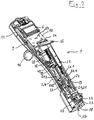
- the electronic manual dosing device 1 is an electronic hand dispenser. It has a bar-shaped housing 2 which is divided longitudinally into a front housing shell 3 and a rear housing shell 4.
- a dial 5 On the front of the housing 2 is located at the top of a dial 5 for selecting the respective operating mode.
- the dial 5 for example, the metering functions pipetting, dispensing and titration are adjustable.
- Including a display 6 is embedded in the front of the housing 2.
- rocker switch 7, 8 which serve to select various menu functions and setting parameters.
- the rocker switch 7, 8 are located on the left and right side of the housing electrical contacts 9, 10 for charging a battery of an electrical power supply 11.
- the battery is housed in the upper part of the housing 2.
- a release button 14 for triggering of suction and dispensing steps and for storing parameter settings.
- a throw-off button 15 In front of the release button 14 is a throw-off button 15 which engages in the downwardly fitting the flat front of the housing 2 bulge 13.
- the housing 2 has a first opening 17 through which a first receptacle 18 in the housing 2 for a syringe flange of a syringe barrel of a syringe is accessible from the outside.
- a first receptacle 18 in the housing 2 for a syringe flange of a syringe barrel of a syringe is accessible from the outside.
- a bell-shaped receiving body 19 located above the first receptacle 18 is a bell-shaped receiving body 19, in which a second receptacle 20 is arranged, which is accessible through a second opening 21 on the underside of the receiving body 19 for insertion of a piston rod end of a syringe plunger of the syringe.
- first receptacle 18 In the first receptacle 18 are first means for releasably holding the syringe flange to a stop 22 in the housing 2, which are designed as syringe gripping lever 23.
- the receiving body 19 has second means for releasable holding in the form of piston gripping levers 24, which serve to releasably hold the syringe plunger in the second receptacle 20.
- the attachment of syringe flange and syringe piston in the first and second receptacles 18, 20 by means of the first and second releasable holding means can be resolved by operating the Abwerfertaste 15 which acts via a gear 25 to the syringe gripping lever 23 and piston gripping lever 24.
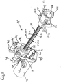
- the syringe plunger is displaceable by means of a metering drive 26.
- the metering drive 26 comprises a spindle drive 27, which has a threaded spindle 28 and a spindle nut 29.
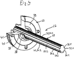
- the threaded spindle 28 has two longitudinally extending first flats 30.1, 30.2 on the two sides and in between two threaded portions 31.1, 31.2 of an external thread 31. According to Fig. 4 and 5 taper in cross section, the threaded portions 31.1, 31.2 in the radial direction to the outside.
- first flats 30.1, 30.2 are outward guide ribs 32.1, 32.2 before.
- Fig. 4 and 5 have the guide ribs 32.1, 32.2 at the outer end second flats 33.1, 33.2.
- they have guide portions 34.1, 34.2, 34.3, 34.4, whose distance from the central axis of the threaded spindle 28 corresponds to half the core diameter of an internal thread 35 of the spindle nut 29.
- Fig. 5 has the external thread 31 trapezoidal thread profiles 36.1, 36.2.
- the radially outer edges of the thread profiles 36.1, 36.2 are rounded.
- the transitions of the flanks 37.1, 37.2 of the thread profiles 36.1, 36.2 to the core of the threaded spindle 28 are rounded on both sides.
- the rounded by the first flats 30.1, 30.2 limited lateral edges of the thread profiles 36.1, 36.2.
- the outer edges of the guide ribs 32.1, 32.2 and the transitions of the guide ribs 32.1, 32.2 to the first flats 30.1, 30.2 are rounded.
- the threaded spindle 28 is injection molded so that the parting plane of the two halves of the injection mold falls into the second flats 33.1, 33.2.
- the rounding of the guide ribs 32.1, 32.2 and the thread profiles 36.1, 36.2 are advantageous for the filling of the injection mold and the removal of the molding from the injection mold.
- the rounding of the profiles 36.1, 36.2 and the guide portions 34.1, 34.2, 34.3, 34.4 are also advantageous for the friction and low-wear adjustment of the threaded spindle 28 in the spindle nut 29th
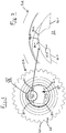
- the spindle nut 29 has a central hollow shaft 38, on whose inner circumference the internal thread 35 is formed.
- the internal thread 35 extends continuously over a first portion of the sleeve.
- the thread profile of the internal thread 35 is also trapezoidal, with the radially inner ends of the profile are rounded and the transitions between the flanks of the profile also.
- a circular disk 39 which is formed as a toothed belt wheel 40 with a toothing 41 on the circumference.
- the hollow shaft 38 projects from the annular disc 39 on both sides.
- the external thread 31 of the threaded spindle 28 and the internal thread 35 of the spindle nut 29 are matched to one another, so that the threaded spindle 28 can be screwed into the spindle nut 29.
- the metering drive 26 according to Fig. 3 an electric drive motor 42 which carries a further toothed belt wheel 44 on a motor shaft 43.
- the spindle nut 29 is rotatably mounted on the hollow shaft 38 in two bearing bushes 45, which is held in two parallel holding plates 46 of a holder 47 at a defined distance from each other and from the drive motor 42.
- the holder 47 has bearing eyes 48 for fixing in the housing 2.
- a toothed belt 49 is placed around to transmit the rotation of the motor shaft 43 to the spindle nut 29.
- the metering drive 26 comprises pin-shaped first guide elements 50.1, 50.2, which protrude in opposite directions from the receiving body 19 to the outside.
- the first guide elements 50.1, 50.2 interact with guide tracks between strip-shaped second guide elements 51.1, 51.2 on the inner sides of the housing shells 3, 4.
- the threaded spindle 28 is prevented from rotating in the housing 2 and the receiving body 19 is guided in the axial direction of the threaded spindle 28.
- the dosing drive 26 includes an electrical control device 52 arranged in the upper region of the housing.
- the control device 52, the electric drive motor 42 and the remaining electronic components of the dosing device are fed by the electric power supply 11.
- the threaded spindle 28 and the spindle nut 29 are made of plastics and / or metal. Preferably, high performance plastics and / or engineering plastics are used for this purpose.
- the threaded spindle 28 and the spindle nut 29 are each made of PEEK.
- the electronic manual dosing device 1 is an electronic handheld pipette. It has an upper housing part 53 in the form of a handle and a substantially cylindrical lower housing part 54.
- the upper housing part 53 contains a drive unit and the lower housing part 54 a displacement unit comprising a cylinder 55 and a piston 56 displaceable therein, which is displaceable by means of the drive unit.
- the upper housing part 53 has a substantially cylindrical body portion 57 and a box-shaped head portion 58, which forms an obtuse angle with the body portion 57.
- the head section has a dial 5 on the front side at the top for selecting the respective operating mode, for example pipetting, dispensing, pipetting and mixing, reverse pipetting, multiple recording, sequential dispensing.
- a display 6 is inserted into the front of the head portion 58.
- rocker button 59 for controlling the recording and dispensing of liquid and the setting of parameters available.
- keys 60 for selecting various menu functions and setting parameters.
- a Abwerfertaste 15 for controlling the ejection of pipette tips 61.
- the Abwereftaste 15 is connected to a Abwerferstange extending in the body portion 57 to the lower end thereof.
- the head portion 58 At the level of the display 6 are on the left and right side of the head portion 58 electrical contacts 9, 10 for charging a housed in the head portion 58 batteries of an electrical power supply 11.
- the battery is connected to a housed in the head portion 58 electrical control device 52.
- the electrical control device 52 is connected to the rocker switch 59 and the other buttons 60, a sensor for detecting the rotational position of the selector wheel 5 and a drive motor 42 of a metering drive 26.
- the body portion 57 has a cavity 62, in which the metering drive 26 is arranged at the top, which will be explained in more detail below.
- the body portion 57 has at the lower end a lower housing opening 63 through which the lower housing part 54 is inserted with its upper end in the cavity 62 of the body portion 57.
- the lower housing part 54 is releasably connected to the upper housing part 53 by means for releasably connecting the lower housing part 54 and the upper housing part 53.
- the means for releasably connecting comprise a latching connection with spring-loaded latching hook 64 of the lower housing part 54 which are latched in the cavity 62 behind locking edges of the upper housing part 53. The locking can be selectively canceled by moving a guided outside the lower housing part 54 Entrastungshülse 65.
- the lower housing part 54 has the cylinder 55 with the piston 56 displaceable longitudinally and sealingly guided therein.
- the cylinder 55 is formed as a bush ( liner ) which is held in a cylinder portion 66 of the housing base 54.
- the cylinder portion is connected at the bottom via a conical connecting portion 67 with a tube 68 having at the lower end a sealing seat 69, on which the pipette tip 61 is clamped.
- the tube 68 defines a communication channel 70 which connects a first hole 71 at the lower end of the cylinder 55 to a second hole 72 in the sealing seat 69 at the lower end of the tube 68.
- the connecting portion 67 and the tube 68 is adapted to the outer shape thereof ejector sleeve 72 for pushing the pipette tip 61 from the sealing seat 69 is pushed.
- the ejector sleeve 73 is connected at the top via detachable coupling means of ejector sleeve 73 and ejector rod to the ejector rod.
- the releasable coupling means consist in a simple case in a clamping fit of the lower end of the Abwerferstange in a bore in a lateral projection on the upper edge of the ejector sleeve 73rd
- the lower housing part 54 carries at the top a closure cap 74 whose cap jacket 75 is connected to the cylinder section 66 and which has a central upper housing opening 77 in a cap bottom 76.
- the piston 56 is connected to a piston rod 78 which carries a plate 79 above. Between plate 79 and upper edge of the cylinder 55, a coil spring 80 is arranged, which presses the plate 79 in an initial position on the underside of the cap bottom 76.
- Fig. 9 to 12 engages the threaded spindle 28 of the metering drive 26 with its lower end through the upper housing opening 77 through into the cap 74 and is located at the top of the plate 79 at.
- FIGS. 12 and 13 corresponds to the metering 26 largely the metering 26 of Fig. 3 so the comments too Fig. 3 Accordingly, for the provided with the same reference numerals of FIGS. 12 and 13 be valid.
- the plate 79 In the metering 26 of FIGS. 12 and 13 contacted the lower end of the threaded spindle 28, the plate 79 and is not connected to a bell-shaped receiving body 19.
- the guide cylinder 81 On the inner circumference, the guide cylinder 81 has two guide grooves 82 which extend in the longitudinal direction of the guide cylinder 81.
- the two guide grooves 82 are diametrically opposite each other.
- Fig. 10 and 13 carries the threaded spindle 28 at the upper end of a sleeve-shaped guide member 83 which has two outwardly projecting guide lugs 84 which engage in the guide grooves 82.
- the guide element 83 is firmly connected to the threaded spindle 28.
- Fig. 14 shows a micrometer 85, which is designed as a micrometer.
- a rigid bracket 86 has a base 87 and two bracket arms 88, 89.
- a circular disk-shaped first measuring jaw 90 is fixed, which has a plane first contact surface at its free end.
- a spindle nut 29 is attached on a second bail arm 89.
- the upper part of the spindle nut 29 is cut away in the drawing for better understanding.
- In an internal thread 35 of the spindle nut 29 engages a threaded spindle 28 with its external thread 31 and forms with this a spindle drive.
- the threaded spindle 28 is firmly connected on one side with a cylindrical second measuring jaw 91, which has a flat second contact surface at its free end.
- the spindle nut has on the outside on a longitudinally extending first scale 92 with a millimeter division.
- the threaded spindle 28 is connected to a measuring sleeve 93 via a friction clutch, not shown ("feeler slide").
- the upper part of the measuring sleeve 93 is cut away in the drawing for better understanding.
- the measuring sleeve 93 has a circumferentially extending second scale 94 with a hundredths of a millimeter division.
- the threaded spindle 28 and the spindle nut 29 are designed according to the invention a spindle drive 27.
- the micrometer 85 is inexpensive to produce, very light and provides accurate measurement results.
Landscapes
- Engineering & Computer Science (AREA)
- General Engineering & Computer Science (AREA)
- Mechanical Engineering (AREA)
- Health & Medical Sciences (AREA)
- Clinical Laboratory Science (AREA)
- Chemical & Material Sciences (AREA)
- Chemical Kinetics & Catalysis (AREA)
- Physics & Mathematics (AREA)
- General Physics & Mathematics (AREA)
- Transmission Devices (AREA)
- Devices For Use In Laboratory Experiments (AREA)
Priority Applications (6)
| Application Number | Priority Date | Filing Date | Title |
|---|---|---|---|
| PL17169766T PL3399215T3 (pl) | 2017-05-05 | 2017-05-05 | Napęd wrzeciona |
| EP17169766.7A EP3399215B1 (fr) | 2017-05-05 | 2017-05-05 | Entraînement de broche |
| PCT/EP2018/061222 WO2018202725A1 (fr) | 2017-05-05 | 2018-05-02 | Entraînement à broche |
| US16/610,983 US11280389B2 (en) | 2017-05-05 | 2018-05-02 | Spindle drive |
| CN201880042154.3A CN110785584B (zh) | 2017-05-05 | 2018-05-02 | 主轴驱动装置 |
| JP2019559773A JP6965369B2 (ja) | 2017-05-05 | 2018-05-02 | スピンドル装置 |
Applications Claiming Priority (1)
| Application Number | Priority Date | Filing Date | Title |
|---|---|---|---|
| EP17169766.7A EP3399215B1 (fr) | 2017-05-05 | 2017-05-05 | Entraînement de broche |
Publications (2)
| Publication Number | Publication Date |
|---|---|
| EP3399215A1 true EP3399215A1 (fr) | 2018-11-07 |
| EP3399215B1 EP3399215B1 (fr) | 2020-07-08 |
Family
ID=58671539
Family Applications (1)
| Application Number | Title | Priority Date | Filing Date |
|---|---|---|---|
| EP17169766.7A Active EP3399215B1 (fr) | 2017-05-05 | 2017-05-05 | Entraînement de broche |
Country Status (6)
| Country | Link |
|---|---|
| US (1) | US11280389B2 (fr) |
| EP (1) | EP3399215B1 (fr) |
| JP (1) | JP6965369B2 (fr) |
| CN (1) | CN110785584B (fr) |
| PL (1) | PL3399215T3 (fr) |
| WO (1) | WO2018202725A1 (fr) |
Cited By (3)
| Publication number | Priority date | Publication date | Assignee | Title |
|---|---|---|---|---|
| EP4134166A1 (fr) | 2021-08-09 | 2023-02-15 | Eppendorf SE | Pipette à utiliser avec une pointe de pipette |
| DE102022105753B3 (de) | 2022-03-11 | 2023-07-06 | Brand Gmbh + Co Kg | Pipettiervorrichtung |
| EP4241887A1 (fr) | 2022-03-11 | 2023-09-13 | Brand Gmbh + Co Kg | Dispositif de pipette |
Families Citing this family (3)
| Publication number | Priority date | Publication date | Assignee | Title |
|---|---|---|---|---|
| CN114731091A (zh) * | 2019-09-23 | 2022-07-08 | 迪宝克技术公司 | 用于运动模拟器的线性致动器 |
| DE102020202196A1 (de) | 2020-02-20 | 2021-08-26 | Thyssenkrupp Ag | Verstellantrieb für eine Lenksäule und Lenksäule für ein Kraftfahrzeug |
| JP7315625B2 (ja) * | 2020-07-14 | 2023-07-26 | エッペンドルフ エスイー | 一体型プランジャを備えたピペット・チップとともに使用するためのピペット |
Citations (7)
| Publication number | Priority date | Publication date | Assignee | Title |
|---|---|---|---|---|
| DE1053883B (de) | 1957-06-03 | 1959-03-26 | Strobach Doerge & Co O H G | Gewindespindel |
| JPS6334361A (ja) * | 1986-07-25 | 1988-02-15 | Sansui Electric Co | ねじ送り装置 |
| US5620660A (en) | 1993-12-03 | 1997-04-15 | Eppendorf-Netheler-Hinz Gmbh | Pipette system |
| EP1449586B1 (fr) | 2003-02-20 | 2006-06-07 | Eppendorf Ag | Système de dosage avec mémoire et méthode pour l'utilisation |
| EP2165765B1 (fr) | 2008-09-12 | 2012-02-15 | Eppendorf Ag | Dispositif de pipetage avec filetage double |
| DE102015212448A1 (de) * | 2015-07-02 | 2017-01-05 | Zf Friedrichshafen Ag | Spindelantrieb und Aktuator mit einem Spindelantrieb |
| WO2017129179A1 (fr) * | 2016-01-29 | 2017-08-03 | HARTING Electronics GmbH | Élément de contact glissant à mouvement linéaire et à dispositif de transport et son procédé de fabrication |
Family Cites Families (13)
| Publication number | Priority date | Publication date | Assignee | Title |
|---|---|---|---|---|
| JPS5322853B2 (fr) * | 1972-07-11 | 1978-07-11 | ||
| US4098125A (en) * | 1977-03-30 | 1978-07-04 | Lee Thomas E | Adjustable volume pipetting device |
| JP3258323B2 (ja) * | 1991-11-29 | 2002-02-18 | ノボ ノルディスク アクティーゼルスカブ | ペン形状をなす注射器 |
| JPH08233831A (ja) * | 1995-02-28 | 1996-09-13 | Suzuki Motor Corp | 電動ピペット保持選択装置 |
| JP4226249B2 (ja) * | 2002-02-13 | 2009-02-18 | Ntn株式会社 | 樹脂製ナットおよびすべりねじ装置 |
| WO2007029716A1 (fr) * | 2005-09-05 | 2007-03-15 | Nsk Ltd. | Mécanisme de vis à bille et procédé pour l’assembler |
| GB0524604D0 (en) * | 2005-12-02 | 2006-01-11 | Owen Mumford Ltd | Injection method and apparatus |
| DE102007008053A1 (de) * | 2007-02-15 | 2008-08-21 | Piras Metalltechnik Gmbh & Co. Kg | Vorrichtung zur Erzeugung einer Linearbewegung |
| JP2010043698A (ja) * | 2008-08-12 | 2010-02-25 | Ntn Corp | 樹脂製ナットおよびすべりねじ装置 |
| SE535983C2 (sv) * | 2010-04-20 | 2013-03-19 | Noviscens Ab | Spruta |
| DE102011106079B4 (de) * | 2011-06-30 | 2020-06-10 | Robert Bosch Gmbh | Planetengewindetrieb mit Enddichtung mit einzelner Dichtkante |
| JP2015517858A (ja) * | 2012-05-30 | 2015-06-25 | サノフィ−アベンティス・ドイチュラント・ゲゼルシャフト・ミット・ベシュレンクテル・ハフツング | 薬物送達デバイスのピストンロッド本体用支承部、ピストンロッド配置、およびピストンロッド本体 |
| CN205479207U (zh) * | 2016-01-19 | 2016-08-17 | 温州万兆汽车零部件有限公司 | 凹槽传动螺杆 |
-
2017
- 2017-05-05 PL PL17169766T patent/PL3399215T3/pl unknown
- 2017-05-05 EP EP17169766.7A patent/EP3399215B1/fr active Active
-
2018
- 2018-05-02 CN CN201880042154.3A patent/CN110785584B/zh active Active
- 2018-05-02 JP JP2019559773A patent/JP6965369B2/ja active Active
- 2018-05-02 US US16/610,983 patent/US11280389B2/en active Active
- 2018-05-02 WO PCT/EP2018/061222 patent/WO2018202725A1/fr active Application Filing
Patent Citations (9)
| Publication number | Priority date | Publication date | Assignee | Title |
|---|---|---|---|---|
| DE1053883B (de) | 1957-06-03 | 1959-03-26 | Strobach Doerge & Co O H G | Gewindespindel |
| JPS6334361A (ja) * | 1986-07-25 | 1988-02-15 | Sansui Electric Co | ねじ送り装置 |
| US5620660A (en) | 1993-12-03 | 1997-04-15 | Eppendorf-Netheler-Hinz Gmbh | Pipette system |
| EP0656229B1 (fr) | 1993-12-03 | 1997-07-16 | Eppendorf-Netheler-Hinz Gmbh | Système de pipette |
| EP1449586B1 (fr) | 2003-02-20 | 2006-06-07 | Eppendorf Ag | Système de dosage avec mémoire et méthode pour l'utilisation |
| US7402440B2 (en) | 2003-02-20 | 2008-07-22 | Eppendorf Ag | Proportioning system and process for operating a proportioning system |
| EP2165765B1 (fr) | 2008-09-12 | 2012-02-15 | Eppendorf Ag | Dispositif de pipetage avec filetage double |
| DE102015212448A1 (de) * | 2015-07-02 | 2017-01-05 | Zf Friedrichshafen Ag | Spindelantrieb und Aktuator mit einem Spindelantrieb |
| WO2017129179A1 (fr) * | 2016-01-29 | 2017-08-03 | HARTING Electronics GmbH | Élément de contact glissant à mouvement linéaire et à dispositif de transport et son procédé de fabrication |
Cited By (4)
| Publication number | Priority date | Publication date | Assignee | Title |
|---|---|---|---|---|
| EP4134166A1 (fr) | 2021-08-09 | 2023-02-15 | Eppendorf SE | Pipette à utiliser avec une pointe de pipette |
| DE102022105753B3 (de) | 2022-03-11 | 2023-07-06 | Brand Gmbh + Co Kg | Pipettiervorrichtung |
| EP4241887A1 (fr) | 2022-03-11 | 2023-09-13 | Brand Gmbh + Co Kg | Dispositif de pipette |
| DE102022105754A1 (de) | 2022-03-11 | 2023-09-14 | Brand Gmbh + Co Kg | Pipettiervorrichtung |
Also Published As
| Publication number | Publication date |
|---|---|
| EP3399215B1 (fr) | 2020-07-08 |
| US20200072329A1 (en) | 2020-03-05 |
| US11280389B2 (en) | 2022-03-22 |
| WO2018202725A1 (fr) | 2018-11-08 |
| JP6965369B2 (ja) | 2021-11-10 |
| PL3399215T3 (pl) | 2021-01-25 |
| CN110785584B (zh) | 2023-04-11 |
| JP2020519817A (ja) | 2020-07-02 |
| CN110785584A (zh) | 2020-02-11 |
Similar Documents
| Publication | Publication Date | Title |
|---|---|---|
| EP3399215B1 (fr) | Entraînement de broche | |
| EP3399214B1 (fr) | Entraînement de dosage électronique | |
| EP2165765B1 (fr) | Dispositif de pipetage avec filetage double | |
| EP2633915B1 (fr) | Pipette avec système de calibration | |
| EP2024090B1 (fr) | Dispositif de maintien de pointes de pipette, pointe de pipette ainsi que dispositif de pipettage | |
| EP2146820B2 (fr) | Machine-outil, notamment machine-outil manuelle | |
| EP1743701B1 (fr) | Pipette à piston | |
| EP2263800A2 (fr) | Pipette avec éjecteur d'embouts de pipette | |
| EP2882554B1 (fr) | Dispositif d'équilibrage ou de mesure | |
| WO1995007785A1 (fr) | Tete d'outil utilisable dans des machines-outils | |
| EP3180139A1 (fr) | Outil multiple | |
| EP3232545A1 (fr) | Moteur électrique | |
| EP3932557B1 (fr) | Tête de pipetage à canaux multiples | |
| EP0886873B1 (fr) | Detecteur de position | |
| EP3892377B1 (fr) | Distributeur et système pour distribuer ou prélever des volumes de liquide | |
| DE20006547U1 (de) | Verstellvorrichtung | |
| DE102021213781B3 (de) | Linearantrieb | |
| EP4331725A1 (fr) | Tige de piston et procédé de fabrication d'une telle tige de piston | |
| DE102023203409A1 (de) | Schubstangeneinheit einer Fahrzeuglenkeinrichtung | |
| EP4206152A1 (fr) | Dispositif de changement d'outil pour un dispositif de formage de récipients en verre | |
| DE102017103744A1 (de) | Dispenser, System und Verfahren zum Aufnehmen und Abgeben von Fluidvolumina | |
| DD148601A1 (de) | Indexiereinrichtung | |
| DD294455A5 (de) | Vorrichtung zur ausfuehrung einer raeumlichen bewegung bei der herstellung gekruemmter formteile aus faserverstaerkten haertbaren kunstharzen |
Legal Events
| Date | Code | Title | Description |
|---|---|---|---|
| PUAI | Public reference made under article 153(3) epc to a published international application that has entered the european phase |
Free format text: ORIGINAL CODE: 0009012 |
|
| STAA | Information on the status of an ep patent application or granted ep patent |
Free format text: STATUS: THE APPLICATION HAS BEEN PUBLISHED |
|
| AK | Designated contracting states |
Kind code of ref document: A1 Designated state(s): AL AT BE BG CH CY CZ DE DK EE ES FI FR GB GR HR HU IE IS IT LI LT LU LV MC MK MT NL NO PL PT RO RS SE SI SK SM TR |
|
| AX | Request for extension of the european patent |
Extension state: BA ME |
|
| STAA | Information on the status of an ep patent application or granted ep patent |
Free format text: STATUS: REQUEST FOR EXAMINATION WAS MADE |
|
| 17P | Request for examination filed |
Effective date: 20190502 |
|
| RBV | Designated contracting states (corrected) |
Designated state(s): AL AT BE BG CH CY CZ DE DK EE ES FI FR GB GR HR HU IE IS IT LI LT LU LV MC MK MT NL NO PL PT RO RS SE SI SK SM TR |
|
| RIC1 | Information provided on ipc code assigned before grant |
Ipc: B01L 3/02 20060101ALN20200115BHEP Ipc: F16H 25/24 20060101AFI20200115BHEP Ipc: G01B 3/18 20060101ALN20200115BHEP Ipc: G01N 35/10 20060101ALN20200115BHEP |
|
| GRAP | Despatch of communication of intention to grant a patent |
Free format text: ORIGINAL CODE: EPIDOSNIGR1 |
|
| STAA | Information on the status of an ep patent application or granted ep patent |
Free format text: STATUS: GRANT OF PATENT IS INTENDED |
|
| INTG | Intention to grant announced |
Effective date: 20200221 |
|
| GRAS | Grant fee paid |
Free format text: ORIGINAL CODE: EPIDOSNIGR3 |
|
| GRAA | (expected) grant |
Free format text: ORIGINAL CODE: 0009210 |
|
| STAA | Information on the status of an ep patent application or granted ep patent |
Free format text: STATUS: THE PATENT HAS BEEN GRANTED |
|
| AK | Designated contracting states |
Kind code of ref document: B1 Designated state(s): AL AT BE BG CH CY CZ DE DK EE ES FI FR GB GR HR HU IE IS IT LI LT LU LV MC MK MT NL NO PL PT RO RS SE SI SK SM TR |
|
| RIN1 | Information on inventor provided before grant (corrected) |
Inventor name: REICHMUTH, BURKHARDT Inventor name: WILTH, MARC Inventor name: SATTLER, JOERG |
|
| REG | Reference to a national code |
Ref country code: CH Ref legal event code: EP Ref country code: AT Ref legal event code: REF Ref document number: 1288802 Country of ref document: AT Kind code of ref document: T Effective date: 20200715 |
|
| REG | Reference to a national code |
Ref country code: DE Ref legal event code: R096 Ref document number: 502017006043 Country of ref document: DE |
|
| REG | Reference to a national code |
Ref country code: IE Ref legal event code: FG4D Free format text: LANGUAGE OF EP DOCUMENT: GERMAN |
|
| REG | Reference to a national code |
Ref country code: FI Ref legal event code: FGE |
|
| REG | Reference to a national code |
Ref country code: DE Ref legal event code: R082 Ref document number: 502017006043 Country of ref document: DE |
|
| REG | Reference to a national code |
Ref country code: LT Ref legal event code: MG4D |
|
| REG | Reference to a national code |
Ref country code: CH Ref legal event code: NV Representative=s name: BOHEST AG, CH |
|
| REG | Reference to a national code |
Ref country code: NL Ref legal event code: MP Effective date: 20200708 |
|
| PG25 | Lapsed in a contracting state [announced via postgrant information from national office to epo] |
Ref country code: SE Free format text: LAPSE BECAUSE OF FAILURE TO SUBMIT A TRANSLATION OF THE DESCRIPTION OR TO PAY THE FEE WITHIN THE PRESCRIBED TIME-LIMIT Effective date: 20200708 Ref country code: BG Free format text: LAPSE BECAUSE OF FAILURE TO SUBMIT A TRANSLATION OF THE DESCRIPTION OR TO PAY THE FEE WITHIN THE PRESCRIBED TIME-LIMIT Effective date: 20201008 Ref country code: HR Free format text: LAPSE BECAUSE OF FAILURE TO SUBMIT A TRANSLATION OF THE DESCRIPTION OR TO PAY THE FEE WITHIN THE PRESCRIBED TIME-LIMIT Effective date: 20200708 Ref country code: ES Free format text: LAPSE BECAUSE OF FAILURE TO SUBMIT A TRANSLATION OF THE DESCRIPTION OR TO PAY THE FEE WITHIN THE PRESCRIBED TIME-LIMIT Effective date: 20200708 Ref country code: LT Free format text: LAPSE BECAUSE OF FAILURE TO SUBMIT A TRANSLATION OF THE DESCRIPTION OR TO PAY THE FEE WITHIN THE PRESCRIBED TIME-LIMIT Effective date: 20200708 Ref country code: PT Free format text: LAPSE BECAUSE OF FAILURE TO SUBMIT A TRANSLATION OF THE DESCRIPTION OR TO PAY THE FEE WITHIN THE PRESCRIBED TIME-LIMIT Effective date: 20201109 Ref country code: GR Free format text: LAPSE BECAUSE OF FAILURE TO SUBMIT A TRANSLATION OF THE DESCRIPTION OR TO PAY THE FEE WITHIN THE PRESCRIBED TIME-LIMIT Effective date: 20201009 Ref country code: NO Free format text: LAPSE BECAUSE OF FAILURE TO SUBMIT A TRANSLATION OF THE DESCRIPTION OR TO PAY THE FEE WITHIN THE PRESCRIBED TIME-LIMIT Effective date: 20201008 |
|
| PG25 | Lapsed in a contracting state [announced via postgrant information from national office to epo] |
Ref country code: RS Free format text: LAPSE BECAUSE OF FAILURE TO SUBMIT A TRANSLATION OF THE DESCRIPTION OR TO PAY THE FEE WITHIN THE PRESCRIBED TIME-LIMIT Effective date: 20200708 Ref country code: LV Free format text: LAPSE BECAUSE OF FAILURE TO SUBMIT A TRANSLATION OF THE DESCRIPTION OR TO PAY THE FEE WITHIN THE PRESCRIBED TIME-LIMIT Effective date: 20200708 Ref country code: IS Free format text: LAPSE BECAUSE OF FAILURE TO SUBMIT A TRANSLATION OF THE DESCRIPTION OR TO PAY THE FEE WITHIN THE PRESCRIBED TIME-LIMIT Effective date: 20201108 |
|
| PG25 | Lapsed in a contracting state [announced via postgrant information from national office to epo] |
Ref country code: NL Free format text: LAPSE BECAUSE OF FAILURE TO SUBMIT A TRANSLATION OF THE DESCRIPTION OR TO PAY THE FEE WITHIN THE PRESCRIBED TIME-LIMIT Effective date: 20200708 |
|
| REG | Reference to a national code |
Ref country code: DE Ref legal event code: R097 Ref document number: 502017006043 Country of ref document: DE |
|
| PG25 | Lapsed in a contracting state [announced via postgrant information from national office to epo] |
Ref country code: DK Free format text: LAPSE BECAUSE OF FAILURE TO SUBMIT A TRANSLATION OF THE DESCRIPTION OR TO PAY THE FEE WITHIN THE PRESCRIBED TIME-LIMIT Effective date: 20200708 Ref country code: CZ Free format text: LAPSE BECAUSE OF FAILURE TO SUBMIT A TRANSLATION OF THE DESCRIPTION OR TO PAY THE FEE WITHIN THE PRESCRIBED TIME-LIMIT Effective date: 20200708 Ref country code: RO Free format text: LAPSE BECAUSE OF FAILURE TO SUBMIT A TRANSLATION OF THE DESCRIPTION OR TO PAY THE FEE WITHIN THE PRESCRIBED TIME-LIMIT Effective date: 20200708 Ref country code: SM Free format text: LAPSE BECAUSE OF FAILURE TO SUBMIT A TRANSLATION OF THE DESCRIPTION OR TO PAY THE FEE WITHIN THE PRESCRIBED TIME-LIMIT Effective date: 20200708 Ref country code: IT Free format text: LAPSE BECAUSE OF FAILURE TO SUBMIT A TRANSLATION OF THE DESCRIPTION OR TO PAY THE FEE WITHIN THE PRESCRIBED TIME-LIMIT Effective date: 20200708 Ref country code: EE Free format text: LAPSE BECAUSE OF FAILURE TO SUBMIT A TRANSLATION OF THE DESCRIPTION OR TO PAY THE FEE WITHIN THE PRESCRIBED TIME-LIMIT Effective date: 20200708 |
|
| PLBE | No opposition filed within time limit |
Free format text: ORIGINAL CODE: 0009261 |
|
| STAA | Information on the status of an ep patent application or granted ep patent |
Free format text: STATUS: NO OPPOSITION FILED WITHIN TIME LIMIT |
|
| PG25 | Lapsed in a contracting state [announced via postgrant information from national office to epo] |
Ref country code: AL Free format text: LAPSE BECAUSE OF FAILURE TO SUBMIT A TRANSLATION OF THE DESCRIPTION OR TO PAY THE FEE WITHIN THE PRESCRIBED TIME-LIMIT Effective date: 20200708 |
|
| 26N | No opposition filed |
Effective date: 20210409 |
|
| PG25 | Lapsed in a contracting state [announced via postgrant information from national office to epo] |
Ref country code: SK Free format text: LAPSE BECAUSE OF FAILURE TO SUBMIT A TRANSLATION OF THE DESCRIPTION OR TO PAY THE FEE WITHIN THE PRESCRIBED TIME-LIMIT Effective date: 20200708 |
|
| PG25 | Lapsed in a contracting state [announced via postgrant information from national office to epo] |
Ref country code: SI Free format text: LAPSE BECAUSE OF FAILURE TO SUBMIT A TRANSLATION OF THE DESCRIPTION OR TO PAY THE FEE WITHIN THE PRESCRIBED TIME-LIMIT Effective date: 20200708 |
|
| PG25 | Lapsed in a contracting state [announced via postgrant information from national office to epo] |
Ref country code: LU Free format text: LAPSE BECAUSE OF NON-PAYMENT OF DUE FEES Effective date: 20210505 Ref country code: MC Free format text: LAPSE BECAUSE OF FAILURE TO SUBMIT A TRANSLATION OF THE DESCRIPTION OR TO PAY THE FEE WITHIN THE PRESCRIBED TIME-LIMIT Effective date: 20200708 |
|
| REG | Reference to a national code |
Ref country code: BE Ref legal event code: MM Effective date: 20210531 |
|
| PG25 | Lapsed in a contracting state [announced via postgrant information from national office to epo] |
Ref country code: IE Free format text: LAPSE BECAUSE OF NON-PAYMENT OF DUE FEES Effective date: 20210505 |
|
| PG25 | Lapsed in a contracting state [announced via postgrant information from national office to epo] |
Ref country code: BE Free format text: LAPSE BECAUSE OF NON-PAYMENT OF DUE FEES Effective date: 20210531 |
|
| REG | Reference to a national code |
Ref country code: DE Ref legal event code: R081 Ref document number: 502017006043 Country of ref document: DE Owner name: EPPENDORF SE, DE Free format text: FORMER OWNER: EPPENDORF AG, 22339 HAMBURG, DE |
|
| PG25 | Lapsed in a contracting state [announced via postgrant information from national office to epo] |
Ref country code: CY Free format text: LAPSE BECAUSE OF FAILURE TO SUBMIT A TRANSLATION OF THE DESCRIPTION OR TO PAY THE FEE WITHIN THE PRESCRIBED TIME-LIMIT Effective date: 20200708 |
|
| P01 | Opt-out of the competence of the unified patent court (upc) registered |
Effective date: 20230527 |
|
| REG | Reference to a national code |
Ref country code: AT Ref legal event code: MM01 Ref document number: 1288802 Country of ref document: AT Kind code of ref document: T Effective date: 20220505 |
|
| PG25 | Lapsed in a contracting state [announced via postgrant information from national office to epo] |
Ref country code: HU Free format text: LAPSE BECAUSE OF FAILURE TO SUBMIT A TRANSLATION OF THE DESCRIPTION OR TO PAY THE FEE WITHIN THE PRESCRIBED TIME-LIMIT; INVALID AB INITIO Effective date: 20170505 Ref country code: AT Free format text: LAPSE BECAUSE OF NON-PAYMENT OF DUE FEES Effective date: 20220505 |
|
| PG25 | Lapsed in a contracting state [announced via postgrant information from national office to epo] |
Ref country code: MK Free format text: LAPSE BECAUSE OF FAILURE TO SUBMIT A TRANSLATION OF THE DESCRIPTION OR TO PAY THE FEE WITHIN THE PRESCRIBED TIME-LIMIT Effective date: 20200708 |
|
| PGFP | Annual fee paid to national office [announced via postgrant information from national office to epo] |
Ref country code: GB Payment date: 20240521 Year of fee payment: 8 |
|
| PGFP | Annual fee paid to national office [announced via postgrant information from national office to epo] |
Ref country code: DE Payment date: 20240521 Year of fee payment: 8 |
|
| PGFP | Annual fee paid to national office [announced via postgrant information from national office to epo] |
Ref country code: CH Payment date: 20240602 Year of fee payment: 8 |
|
| PGFP | Annual fee paid to national office [announced via postgrant information from national office to epo] |
Ref country code: FR Payment date: 20240528 Year of fee payment: 8 Ref country code: FI Payment date: 20240527 Year of fee payment: 8 |
|
| PGFP | Annual fee paid to national office [announced via postgrant information from national office to epo] |
Ref country code: PL Payment date: 20240426 Year of fee payment: 8 |
|
| PG25 | Lapsed in a contracting state [announced via postgrant information from national office to epo] |
Ref country code: MT Free format text: LAPSE BECAUSE OF FAILURE TO SUBMIT A TRANSLATION OF THE DESCRIPTION OR TO PAY THE FEE WITHIN THE PRESCRIBED TIME-LIMIT Effective date: 20200708 |